

Page 1
Page 2
Precautions
● Do not expose the plug-in board to direct sunlight, ex-
cessive humidity, high temperatures, excessive dust or
strong vibrations.
● Before handling the plug-in board, be sure to touch a
metal surface to discharge any static electricity which
may be in your body.
● When holding the plug-in board, do not touch the in-
side area of the circuit board or apply excessive pressure to the board, and be sure to protect the board from
● Before connecting the computer to other devices, turn
off the power switches of all devices.
● Y amaha is not responsible for loss of data through com-
puter malfunctions or operator actions.
● The plug-in board contains no user-serviceable parts,
so never touch the inside area of the circuit board or
tamper with the electronic circuitry in any way. Doing
so may result in electrical shock or damage to the plugin board.
contact with water or other liquids.
● Before installing the plug-in board onto a tone genera-
tor/sound card, unplug the power connector of your computer.
* The company names and product names in this Owner’s Manual are the trademarks or regis-
tered trademarks of their respective companies.
* The screens as illustrated in this owner’s manual are for instructional purposes only, and may
appear somewhat different from the ones of your instrument.
FCC INFORMATION (U.S.A.)
1. IMPORTANT NOTICE: DO NOT MODIFY THIS UNIT!
This product, when installed as indicated in the instructions contained in this manual, meets FCC requirements. Modifications
not expressly approved by Yamaha may void your authority, granted by the FCC, to use the product.
2. IMPORTANT: When connecting this product to accessories and/or another product use only high quality shielded cables.
Cable/s supplied with this product MUST be used. Follow all installation instructions. Failure to follow instructions could void
your FCC authorization to use this product in the USA.
3. NOTE: This product has been tested and found to comply with the requirements listed in FCC Regulations, Part 15 for Class
”B” digital devices. Compliance with these requirements provides a reasonable level of assurance that your use of this product
in a residential environment will not result in harmful interference with other electronic devices. This equipment generates/
uses radio frequencies and, if not installed and used according to the instructions found in the users manual, may cause
interference harmful to the operation of other electronic devices. Compliance with FCC regulations does not guarantee that
interference will not occur in all installations. If this product is found to be the source of interference, which can be determined
by turning the unit ”OFF” and ”ON”, please try to eliminate the problem by using one of the following measures:
Relocate either this product or the device that is being affected by the interference.
Utilize power outlets that are on different branch (circuit breaker or fuse) circuits or install AC line filter/s.
In the case of radio or TV interference, relocate/reorient the antenna. If the antenna lead-in is 300 ohm ribbon lead, change
the lead-in to co-axial type cable.
If these corrective measures do not produce satisfactory results, please contact the local retailer authorized to distribute this
type of product. If you can not locate the appropriate, please contact Yamaha Corporation of America, Electronic Service
Division, 6600 Orangethorpe Ave, Buena Park, CA 90620
Y AMAHA CANNO T BE HELD RESPONSIBLE
FOR DAMAGE CAUSED BY IMPROPER
CARE AND USE OF THE PLUG-IN BOARD.
* This applies only to products distributed by YAMAHA CORPORATION OF AMERICA.
CANADA
This Class B digital apparatus complies with Canadian ICES-003.
Cet appareil numérique de la classe B est conforme à la norme NMB-003 du Canada.
• This applies only to products distributed by Yamaha Canada Music Ltd.
• Ceci ne s’applique qu’aux produits distribués par Yamaha Canada Musique Ltée.
2
Page 3
Introduction
Thank you for purchasing the Yamaha XG Plug-in board PLG100-DX.
The PLG100-DX is a plug-in board that offers a six-operator FM generator equivalent to the one that
made the DX7 series so famous. The PLG100-DX is compatible with the XG plug-in system, and you
can install it into the MU128 or any other tone generator or sequencer that supports XG plug-ins. Once
it’s installed, the unique FM tone generator voices that built the reputation of the DX series will be right
at your fingertips, ready to play. The PLG100-DX has 912 preset DX series voices built right in, and
you can send the DX7 and DX7II voice data through MIDI.
To install your PLG100-DX correctly, and to ensure full enjoyment of its outstanding functions, be sure
to read this manual very carefully. After you finish reading your owner’s manual, be sure to keep it
someplace safe, where you can refer to it whenever you have a question about your PLG100-DX.
Table of Contents
About the PLG100-DX ......................................... 4
Features of the PLG100-DX ..................................... 4
Installing the PLG100-DX ......................................... 4
Included Items .......................................................... 5
Necessary Items that Are Not Included .................. 5
Specifications ........................................................... 6
About the CD-ROM ................................................... 7
Installing and Starting the Plug-in Software .......... 8
FM Tone Generation ........................................... 10
Operators ................................................................ 10
Combinations of Two Operators ........................... 11
Carrier and Modulator ............................................ 12
Harmonics ............................................................... 13
Algorithms............................................................... 14
Feedback ................................................................. 14
Essentials for Determining Voices ....................... 15
Memory Buffer Configuration........................ 18
About the XG Plug-in System
With the Yamaha XG Plug-in System, you can expand your tone generation system by simply
mounting an optional board onto the “mother” tone generator/sound card. For example, you will
be able to use extra voices from a different sound synthesis such as Virtual Acoustic Synthesis,
apply a completely new dimension to your music, and/or add the latest technology to your music.
DX Voice Selection................................................ 19
Choosing the Voices to be Used........................... 19
Specifying Part/Performance Layers .................... 20
Editing DX Part Parameters............................ 21
PLG100-DX Part Parameters ................................. 22
PLG100-DX System Parameters.................... 26
System Parameters ................................................ 27
Appendix ................................................................... 28
Chart of Algorithms ................................................ 28
Voice List................................................................. 30
Performance List .................................................... 38
MIDI Data Format .................................................... 39
MIDI Implementation Chart .................................... 50
Glossary .................................................................. 52
When Your PLG100-DX Seems to Have a Problem..
Conditions for Using the Software........................ 61
Guide to User Support Services ........................... 62
59
About DX-XG
The DX Extension for XG (“DX Extension for XG” is abbreviated to DX-XG) included in the
PLG100-DX significantly enhances and expands the musical capabilities of the XG format with
the superior sound and expressive potential of Yamaha FM synthesis. The PLG100-DX supports
the same powerful FM synthesis voices as Yamaha’s legendary DX7. Plug this board into your
tone generator/sound card for 912 unbelievable FM voices with up to 16-note polyphony.
3
Page 4
About the PLG100-DX
Features of the PLG100-DX
• Features the same FM tone generator that has won acclaim in the DX
series synthesizers.
The PLG100-DX employs an FM tone generator system, with six operators and 32
algorithms, that has been a favorite of musicians in DX series synthesizers like the
DX7 and the DX7II.
• Maximum 16 voice simultaneous polyphony
Ensures maximum 16 voice simultaneous polyphony equal to the DX7 and DX7II.
Furthermore, by installing multiple PLG100-DX boards, the maximum polyphony can
be increased to 128 voices (when eight boards are installed). By installing, for example, three PLG100-DX boards in the MU128 tone generator, maximum polyphony
will be 48 voices.
• 912 preset voices
The PLG100-DX already has 912 preset voices built right in. From electric piano to
bass, and reaching all the way to effect sounds, the preset voices have been selected for
usability centering on the sounds that made the DX series famous.
• Voice data can be exchanged in bulk between the DX7 and the DX7II
Because the PLG100-DX is compatible with the DX series, it can be used for bulk
transfer of voice parameters between the DX7 and the DX7I I. The DX7 and DX7II can
be used as editors for the PLG100-DX. By using the edit software for the DX7 and the
DX7I I, editing can be done for the PLG100-DX. Voice parameters for the DX1, DX7S,
TF1 (such as the TX816) TX7 and the TX802 are also supported.
• Some voices may sound slightly different than the voices of the devices mentioned above.
• Comes equipped with a low pass filter, a high pass filter and a two-band
equalizer.
A low pass filter, a high pass filter and a two-band equalizer have been installed in the
PLG100-DX. These features can be used together with the voice editing parameters for
the FM tone generator to create new voices. Even if you install the PLG100-DX in a
platform that doesn’t have these functions, the filters and EQ built into the PLG100DX will work.
• Compatible with the XG Plug-In system
Because the PLG100-DX is an XG plug-in board, it can be installed in any XG plug-in
tone generator, like the MU128.
Installing the PLG100-DX
To install your PLG100-DX board, see the manual that came with the “mother” tone generator (such as the MU128 or SW1000XG) or synthesizer.
4
Page 5

Included Items
The items below are packaged together with your new PLG100-DX. Before using your
board, be sure to check that everything has been included. In the rare event that some item
is missing, please contact the store where you bought your PLG100-DX as soon as possible.
● PLG100-DX Board
● PLG100-DX Owner’s Manual
● CD-ROM “XGtools”
Necessary Items that Are Not Included
XG tone generator or synthesizer
To use your PLG100-DX, you will need an XG tone generator or synthesizer equipped
with an XG Plug-in platform function that is compatible with the XG Plug-in system,
such as the MU128 or SW1000XG.
About the PLG100-DX
The MU128 and SW1000XG are equipped with each of the XG Plug-in platform functions, and can be used for installing the PLG100-DX.
The software programs explained below will put the functions of the PLG100-DX right
at your fingertips, helping you get the most enjoyment out of it.
XGworks(lite)
When you use Yamaha’s XGworks(lite) as your sequence software, you can take advantage of the two editing software programs explained below, the “DX Simulator”
and the “DX Easy Editor.” These programs make it really easy to edit the voices of
your PLG100-DX board.
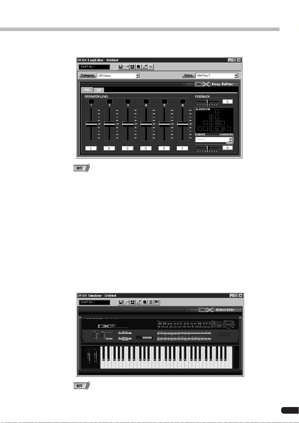
DX Easy Editor
The DX Easy Editor lets you indirectly change the PLG100-DX voices by changing the
part parameters. It’s not for directly editing the voice parameters. Using this software,
you can edit both the XG part parameters (XG parameters) that are shared by all the
parts, and the native part parameters that are specially for the PLG100-DX (DX parameters). The changed parameters can be either inserted into the song as events, or saved
as a DX parameter file.
Because the DX Easy Editor is plug-in software for XGworks(lite), you must have
XGworks(lite) in order to use it.
The DX Easy Editor is included on the CD-ROM that was packaged with your PLG100DX board.
5
Page 6

About the PLG100-DX
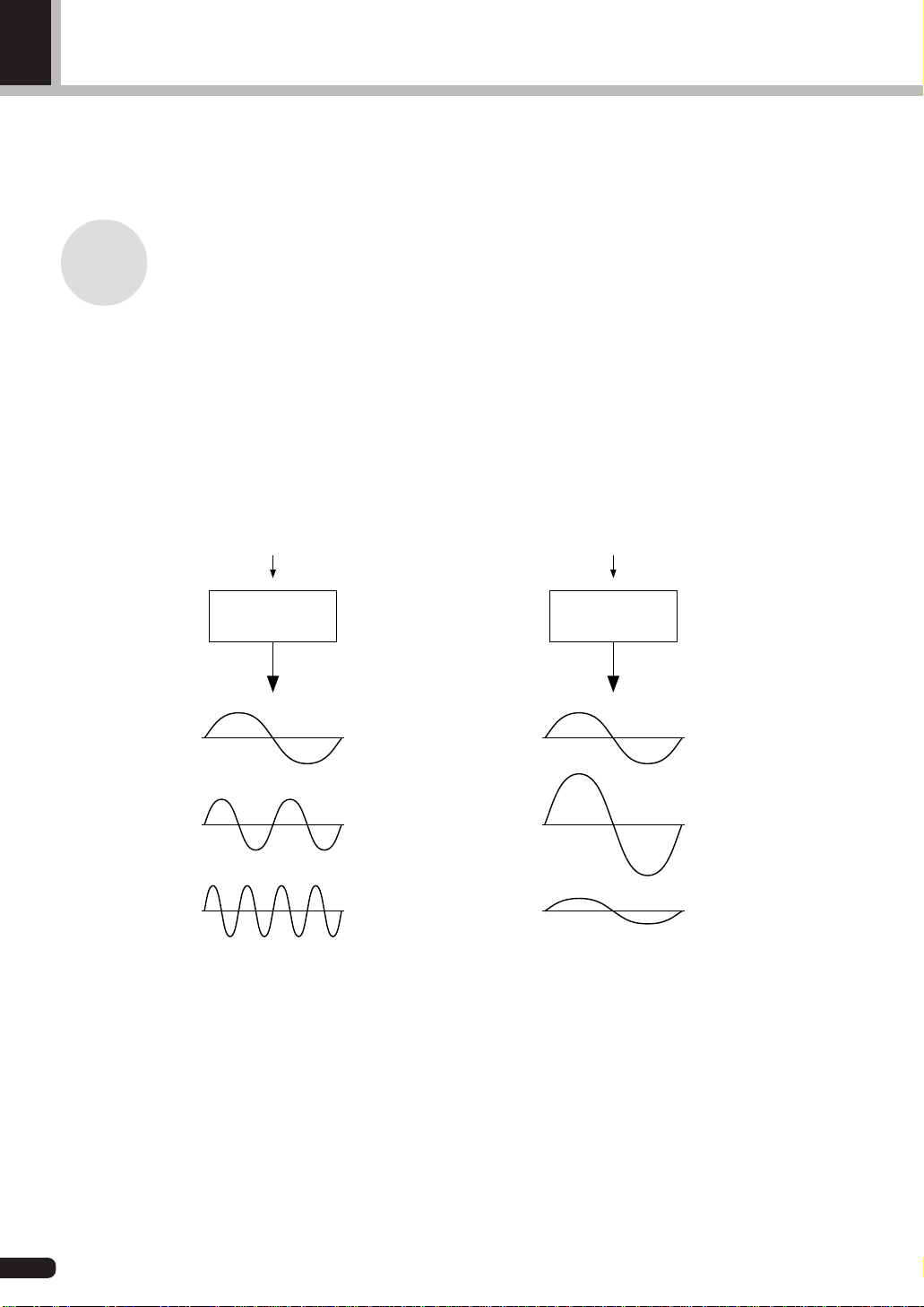
DX Simulator
The DX Simulator is special software for editing the custom voices of the PLG100DX. When you start up the program, an image of the DX7 front panel is displayed on
your computer screen. Using your mouse to operate the buttons and sliders, you can
edit voices just like using a real DX7. You can also display an edit list where you can
edit voices while checking all the parameters in a table on the screen. The edited voice
data can be either saved in memory or to a file, or can be inserted into a track as bulk
data.
Because the DX Simulator is plug-in software for XGworks(lite), you must have
XGworks(lite) in order to use it.
The DX Simulator is included on the CD-ROM that was packaged with your PLG100DX board.
Specifications
Tone Generator Type:
FM tone generator with six operators and 32 algorithms
Maximum Simultaneous Polyphony:
16 notes (latest note priority)
By using multiple boards in combination, polyphony can be expanded to a maximum of 128 notes (with 8
boards)
Filters:
Part EQ (two band), low pass filter, high pass filter (effective only when the platform for the PLG100-DX
has no filter functions)
Interface:
XG Plug-in connector
Number of Voices:
912 preset voices, 64 custom voices
Bulk Information that Can Be Received from Other Devices:
DX7 Voice Edit Buffer, Packed 32 Voice
DX7II Voice Edit Buffer, Packed 32 voice, a portion of the Additional Edit Buffer, a portion of the
Packed 32 Additional (Pitch EG range, rs, velocity switch, Unison detune, AMS, Random pitch,
Poly/Mono, Unison Sw, Pitch bend range, step, Portamento mode, step, time)
Parameter Changes that Can Be Received from Other Devices:
DX7 VCED, a portion of ACED (Pitch EG range, rs, velocity switch, Unison detune, AMS, Random
pitch, Poly/Mono, Unison Sw, Pitch bend range, step, Portamento mode, step, time)
Dimensions:
138.5mm (W) x 89.0mm (D) x 8.5mm (H)
Weight 63g
Included Items:
Owner’s Manual, CD-ROM x 1
*Specifications or dimensions may change without notice due to improvements in this product.
6
Page 7

About the CD-ROM
In addition to the two plug-in software programs, DX Simulator and DX Easy Editor, the
CD-ROM that was packaged with your board also contains several demonstration songs
that showcase the special features of the PLG100-DX, and also performance data (voice
settings) for use in the platform where you have installed your PLG100-DX. The demonstration songs can be enjoyed by playing them with sequence software like XGworks
V2.0 or XGworks(lite), or with a QY700. (A platform for connecting the PLG100-DX is
also necessary.) Use the same sequence software or device to send the performance data
as bulk data to the platform for the PLG100-DX.
● Demonstration Songs
“Ie Kia Bara Hein” (IeKiaBar.MID) by Noritaka Ubukata (Shofuku)
The title of the song means “What kind of spell is this?” in the Hindi language. It
features the voice that simulates a santur (hammer dulcimer) together with a sitar.
About the PLG100-DX
“DX VOICE” (DXVoice.MID) by Noritaka Ubukata (Shofuku)
Starting with the electric piano, this song features a series of the sounds of DX7
Shofuku. Unlike sampling, this music offers the listener subtle variation in the sound
caused by changes in velocity. Another special feature is the FM choir, where a more
realistic sound is created by combining FM synthesis with sampled human voices.
“Vel&EffectWorks1” (V1_EfWk1.MID)
“Vel&EffectWorks2” (V1_EfWk2.MID)
“DX Short Demo” (DxShtDM.MID) by Yasuhiko Fukuda (Shofuku)
These songs showcase a unique feature of FM: the violent changes in sound that are
caused by velocity.
“80’s Pops” (80Pop.MID) by Katsumi Nagae (Idecs Inc.)
Recalls the pop scene of the 80’s with synpads and metallic sounds like dum bells.
“D-Rock” (D-Rock.MID) by Katsumi Nagae (Idecs Inc.)
This song brings back the digital rock sound using the noise and SE system voices
that only DX has.
If you want to use digital noise, there is nothing that works like DX!
“EP Ballade” (EP.MID) by Katsumi Nagae (Idecs Inc.)
If it’s ballads you want—well, there is nothing like DX electric piano.
The voice in the electric piano part will also work with different electric pianos. Try
playing the song with different piano voices.
7
Page 8

About the PLG100-DX
“House” (HOUSE.MID) by Katsumi Nagae (Idecs Inc.)
The typical house music sound is simulated in this song, which experiments with
reproducing sampling phrases using the DX Voice system. In addition, the second
half of the song features the metalic sound that is a strong point of the DX.
“Jungle” (DXJungle.MID) by Katsumi Nagae (Idecs Inc.)
This song adds a touch of Chinese feeling to the Jungle. The Oriental image is underscored by the “CHINA_S&” and “IMAGE9” plug-in SE voices.
If no sounds are played, or if you experience other problems with playback, see Appendix “When Your PLG100-DX Seems to Have a Problem” (→P. 59).
Installing and Starting the Plug-in Software (Windows95 only)
■ Installing the Plug-in Software.......................................................
Double-click on the Setup.exe file in the Plug_ folder on the CD-ROM to start the
installation.
Click on “Next” or “Yes” as these words appear on the screen to complete the installation.
■ Starting the DX Easy Editor............................................................
1. Start XGworks(lite).
2. Select “DX Easy Editor” from the XGworks(lite) plug-in menu.
The “Select DX Part” dialog will open.
3. Set the part numbers to be assigned to the PLG100-DX, then click on the [OK]
button. If there is DX bulk data in the sequence data, the DX mark will be displayed under the part number.
8
Page 9
About the PLG100-DX
Open the DX Easy Editor Window
• For details about using the DX Easy Editor, see the help file that comes with the DX Easy Editor.
• If the DX Easy Editor does not appear on the Plug-In menu of XGworks(lite), the program may
not be properly installed in the XGworks(lite) folder. You can install it by running the plug-in
installation program.
■ Starting the DX Simulator...............................................................
1. Start XGworks(lite).
2. Select “Select DX Simulator” from the XGworks(lite) plug-in menu.
The “Select DX Part” dialog will open.
3. Set the part numbers to be assigned to the PLG100-DX, then click on the [OK]
button. If there is DX bulk data in the sequence data, the DX mark will be displayed under the part number.
Open the DX Simulator Window
• For details about using the DX Simulator, see the help file that comes with it.
• If the DX Simulator does not appear on the Plug-In menu of XGworks(lite), the program may not
be properly installed in the XGworks(lite) folder. You can install it by running the plug-in installation program.
9
Page 10
FM Tone Generation
Before actually editing the PLG100-DX voices, let’s get an idea of how the FM tone generator is
put together.
Operators
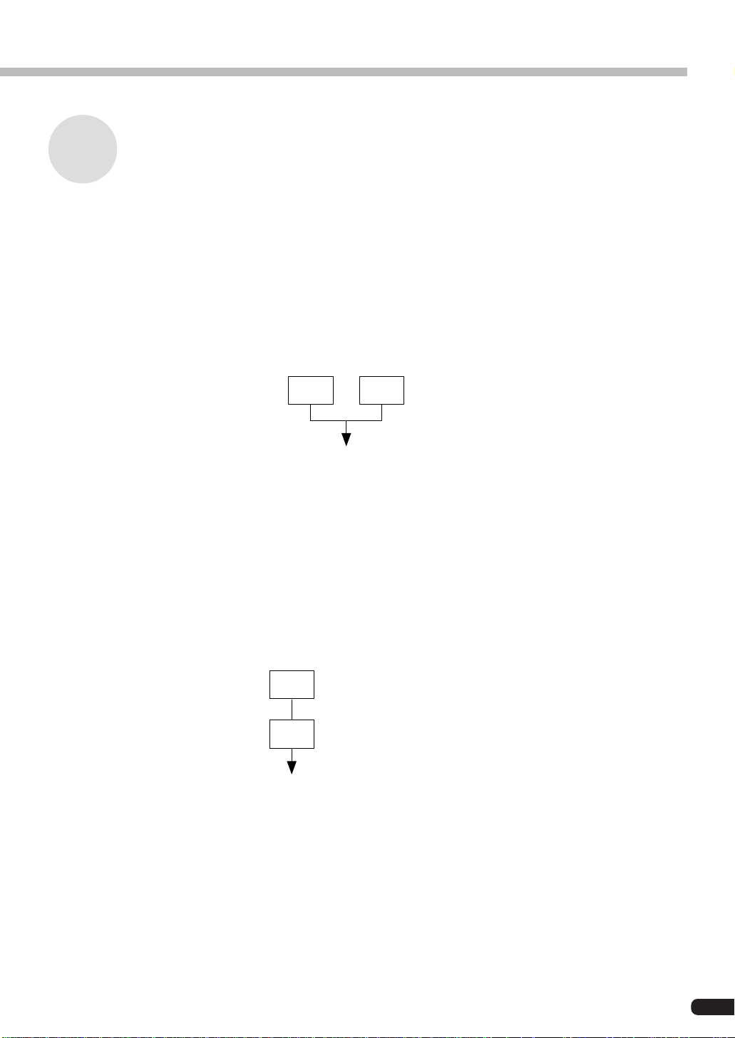
In the PLG100-DX, there are six special devices called “operators” that generate sine
waves. These six operators are combined in various ways to make up the different voices
produced by the PLG100-DX. The operators have the following two functions:
(1) They can freely change the frequency (pitch) of the generated sine wave.
(2) They can freely change the amplitude (volume or output level) of the generated
sine wave.
A sine wave is the fundamental wave of a note, with absolutely no overtones added.
Command
Operator
The frequency of
the sine wave is
changed.
Command
Operator
The amplitude
of the sine wave
is changed.
10
Page 11
Combinations of Two Operators
Although the six operators can be combined in myriad ways, here the fundamental combinations that involve two operators will be explained.
Two operators can be combined in the following two ways (the two operators will be
called A and B respectively):
(1) Horizontal Combination
When the two operators are combined horizontally, the sound generated by each is mixed
with the sound from the other. The actual sound (sine wave) is produced by A and B acting
together.
FM Tone Generation
A B
Mixed sound of A and B
The actual sound is generated by
A and B together
(2) Vertical Combination
When the two operators are combined vertically, the upper operator B works to change the
sound of the lower operator A, and a complex waveform with many overtones added to it
will be the output from operator A. In this situation, the B operator serves only to change
the sound of operator A, and does not generate the actual sound. Operator A generates the
actual sound as it undergoes changes caused by B. When the upper operator works to
change the sound of the lower operator in this way, it is called FM modulation (or simply
modulation).
B
B changes the sound of A (it generates no tone).
While A undergoes changes caused by B, it generates
A
the actual sound.
When these are put together, it looks like this:
• Horizontal Combination The two operators both generate the sound.
• Vertical Combination One operator is for changing the sound of the other operator.
One operator is for making the sound.
When two operators are combined vertically in this way, they both work completely differently.
11
Page 12
FM Tone Generation
Carrier and Modulator
To distinguish the two operators when they are combined vertically, they are called the
“Carrier” and the “Modulator.”
• Carrier ................. The operator in the lowest position, that produces the actual sound. (Called A
• Modulator ............ An operator positioned above another operator, which changes (modulates)
When there are three or more operators, each operator is classified as a carrier or modulator in the same way.
in the previous section.)
the sound of the next operator down. (Called B in the previous section.)
(1)
C C C
(5)
M M
C C
(2)
M
M
C
(3)
M
C
“C” Carrier
“M” Modulator
C
(4)
M M
C
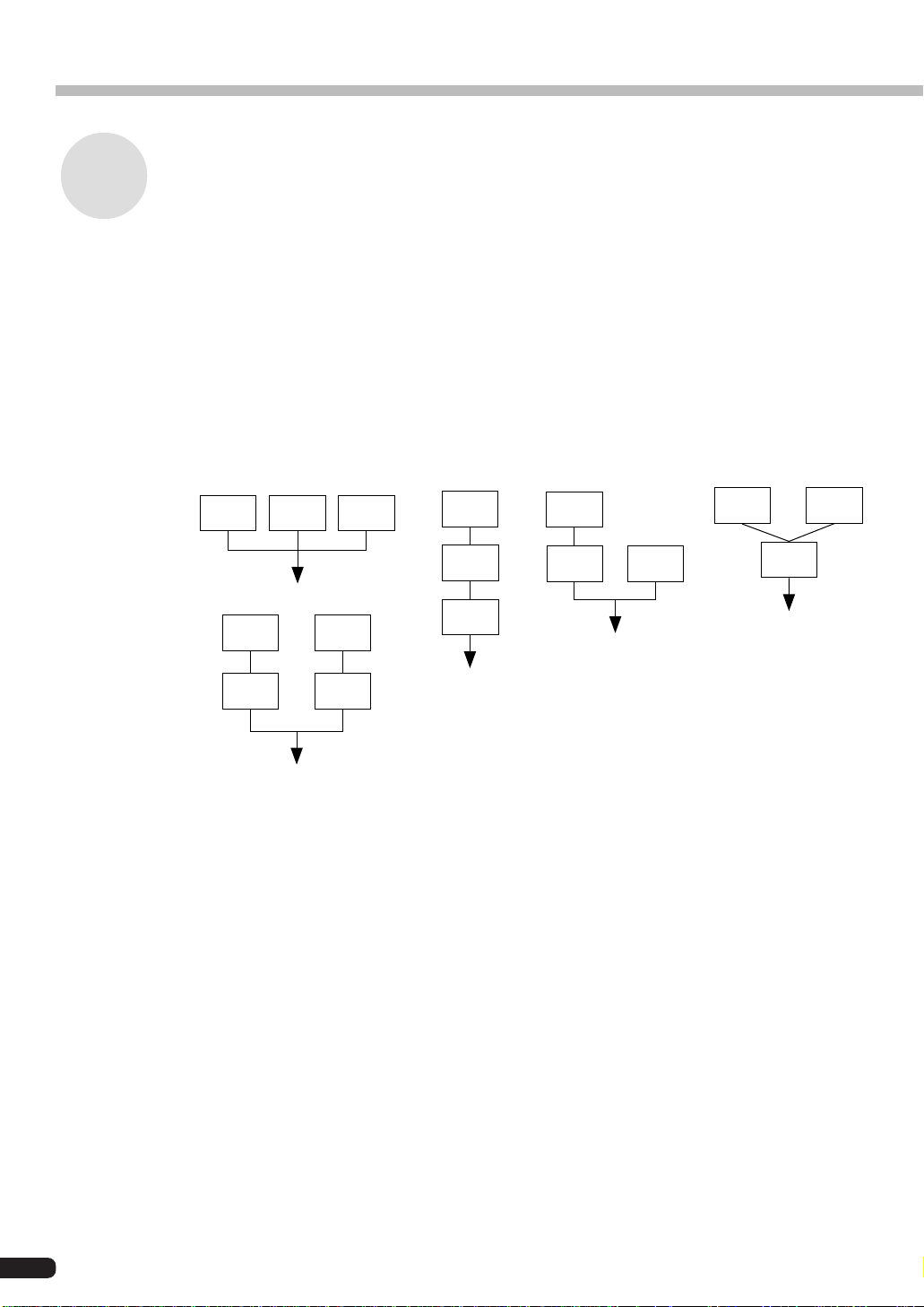
(1) When all the operators are combined horizontally, there is no modulator and they are
all carriers. Because there is no modulation, all waveforms generated by the carriers
are sine waves.
(2) When three operators are piled vertically, only the lowest operator is a carrier. The
modulator on the top modulates the lower modulator, and the modulated waveform
from the lower modulator in turn modulates the carrier. The modulation of the carrier
becomes deeper and the sound output has more overtones.
12
(3) Here there are two carriers and one modulator. The modulator modulates the carrier
immediately below it. The modulated carrier generates sound with overtones. The
other carrier produces a pure sine wave. Finally, the sound from the two carriers is
mixed to form the whole sound.
(4) Here there is one carrier and two modulators. The two modulators each independently
modulate the single carrier. Since the carrier is modulated by the two modulators, it
generates a sound that has more overtones.
(5) Here there are two sets of two operators that have been combined vertically. In each of
them, the modulator modulates the carrier immediately below it, and the carrier generates a sound that has overtones. Finally, the sound from the two carriers is mixed to
form the whole sound.
Page 13
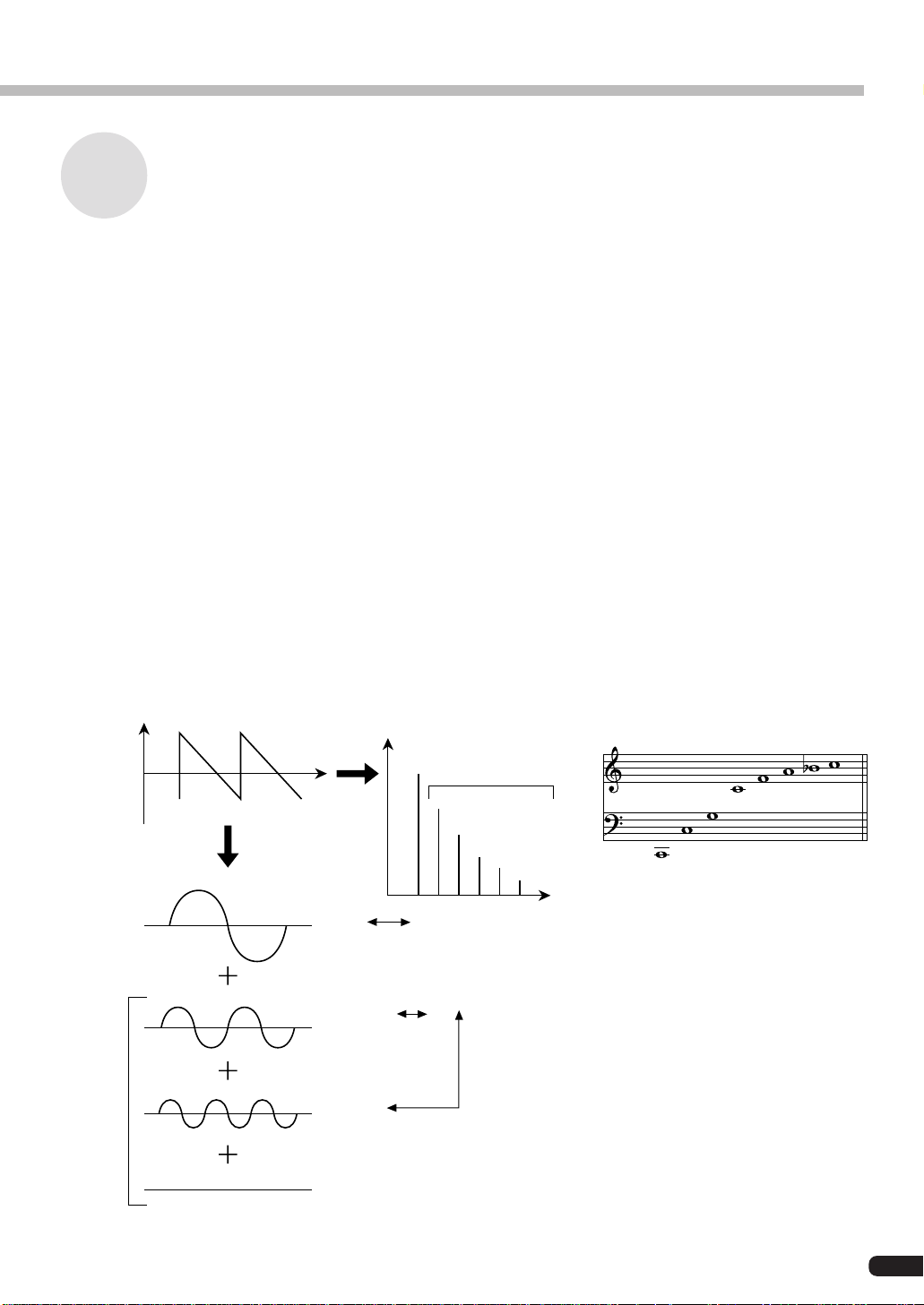
Harmonics
Most sounds are made up of multiple tones that are different than the pitch (frequency).
Within these multiple tones, the one that determines the pitch of the entire sound is called
the fundamental tone (fundamental frequency). All the tones besides the fundamental tone
are called partials or overtones.
When all the harmonics that are related to a particular fundamental tone are arranged in
order, it is called a harmonic series. Each tone in the harmonic series is given a name in
order, with the fundamental tone being one, followed by the second harmonic, third harmonic and so on.
The frequency of each harmonic in the harmonic series is a natural number multiple of the
frequency of the fundamental tone. Overtones that have frequencies that are not natural
number multiples of the fundamental are called unharmonic overtones.
Generally, the more harmonics the tone has, the brighter the sound. On the other hand, if
the amount of harmonics is reduced, the tone will sound darker. Furthermore, the voice
will change a lot according to the type and volume of the harmonics. For example, if there
are a lot of high pitched harmonics in the tone, it will have a brilliant, crisp sound. On the
other hand, a tone with a large amount of lower harmonics will have a rather massive,
dignified sound.
FM Tone Generation
Harmonics
Level
Harmonics
Waveform
Fundamental Wave
Second Harmonic
Third Harmonic
Time
Level
Graph of the Harmonics
that Make Up the Tone
Harmonics
Fourth Harmonic
Third Harmonic
Second Harmonic
Fundamental
Frequency
Natural Harmonic Series
(when C1 is the fundamental tone)
Eighth Harmonic
Seventh Harmonic
Sixth Harmonic
Fifth Harmonic
Fourth Harmonic
Third Harmonic
Second Harmonic
Fundamental
13
Page 14
FM Tone Generation
Algorithms
While there may be only two ways to combine two operators, when you start talking about
six operators, the number of possible combinations becomes much larger. These combinations of six operators are called “algorithms,” and in both the DX7 series and the PLG100DX, 32 of these combinations have been selected that can be used for creating voices.
In an FM tone generator, which operators work as carriers and which work as modulators
are changed dynamically by the algorithms. For this reason, the first thing you have to
know when editing a voice is which algorithm is used by that voice.
The algorithms are numbered from 1 to 32. For information about the 32 algorithms, see
“Appendix, Chart of Algorithms” (→P. 28).
The six operators have also been numbered from one to six to help in distinguishing them.
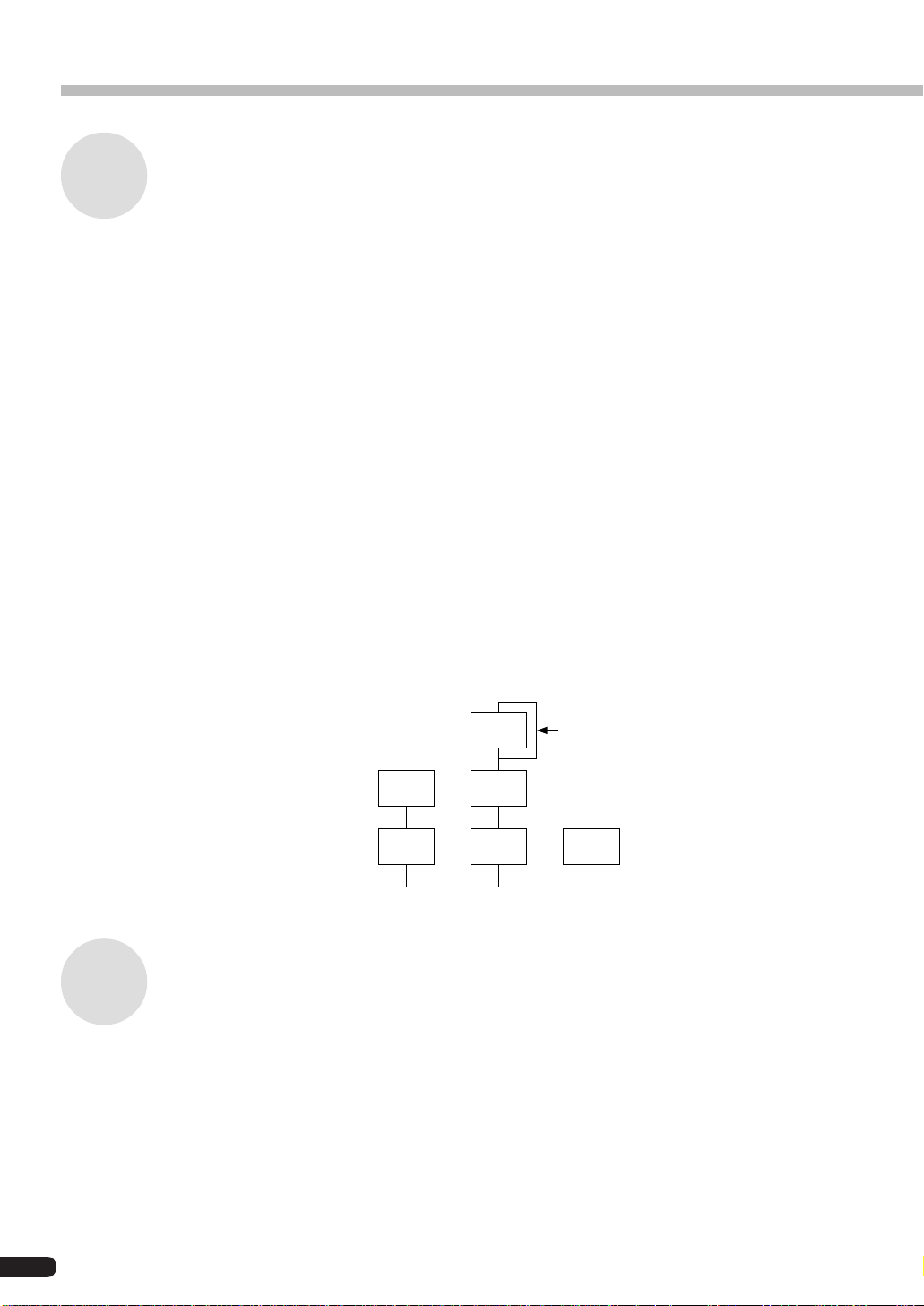
Let’s take algorithm 28 as an example. In this algorithm, the operators work as follows:
Operator 1 ............. Outputs sounds while being modulated by Operator 2 (Carrier).
Operator 2 ............. Modulates Operator 1 (Modulator).
Operator 3 ............. Outputs sounds while being modulated by Operator 4 (Carrier)
Operator 4 ............. Modulates Operator 3 while being modulated by Operator 5 (Modulator)
Operator 5 .............
Operator 6 ............. Outputs a sine wave (Carrier)
Modulates Operator 4 while being modulated with its own feedback (Modulator).
Feedback
Feedback is a function where a portion of the output of an operator is returned back to the
operator again, where it is used to modulate the operator itself. Using feedback results in a
deeper sound.
Every one of the 32 algorithms has feedback set in one location. Among them there is even
one algorithm, number 4, where the output of three operators as a group is used as feedback. When a portion of the output of operator 4 in this algorithm is returned to operator 6,
an extremely deep sound is obtained.
Algorithm 28
5
2 4
1 3 6
Feedback
(See next section)
14
Page 15
FM Tone Generation
Algorithm 4
3
2
1
Essentials for Determining Voices
Voices are determined by the following main elements:
(1) The output level from each operator (OUTPUT LEVEL).
(2) The frequency of the tone put out by each operator
(OUTPUT FREQUENCY).
(3) The feedback level (FEEDBACK LEVEL).
(4) The Envelope Generator (EG).
Each of these will be explained in order.
6
5
4
Feedback
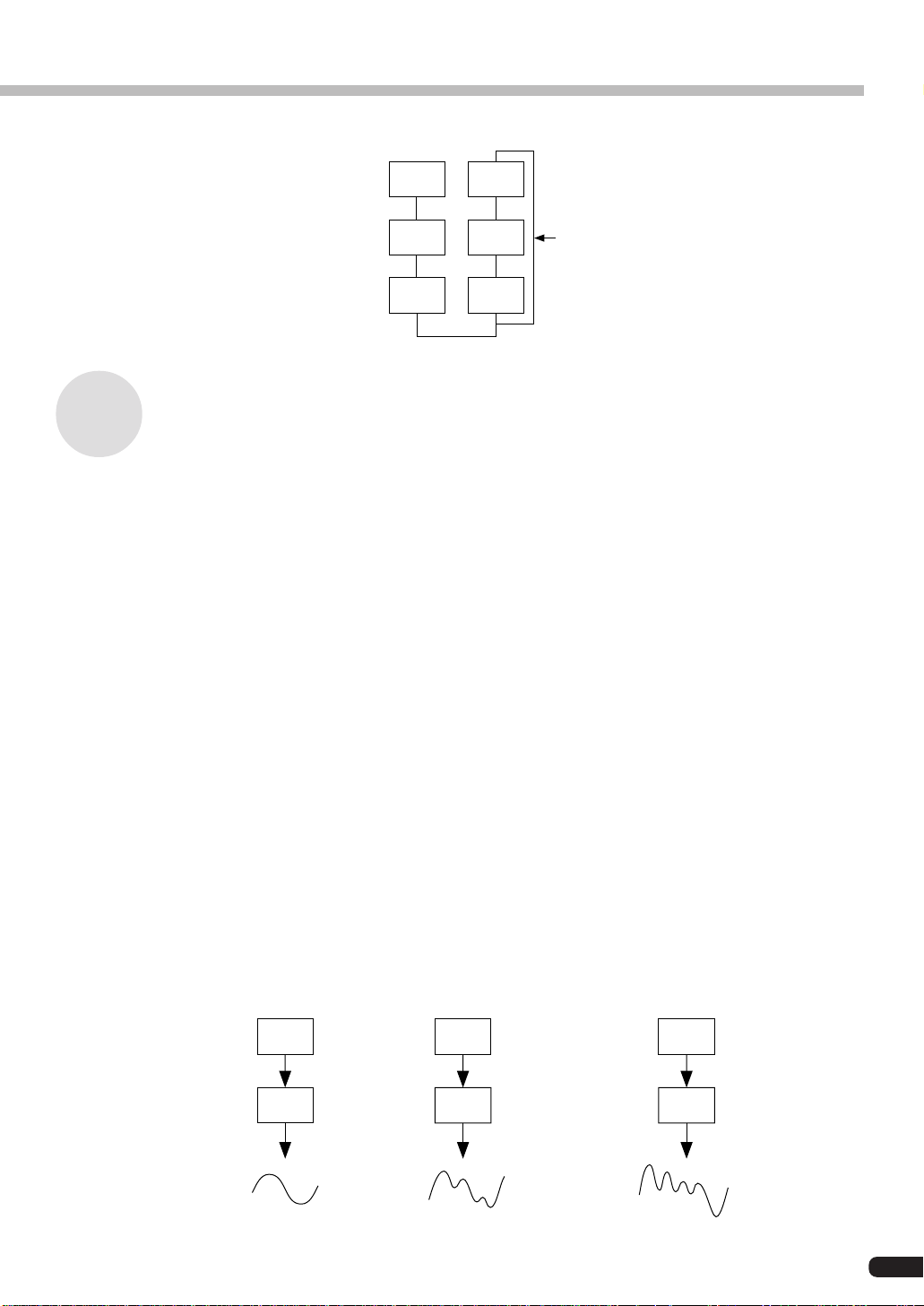
(1) The output level from each operator
When voices are edited, the most important point is the output level for each operator.
Among these, the output level of the modulator has the largest effect on the voice. For
example, when two operators are vertically combined, and the output level of modulator B
is set to zero, the output waveform of carrier A will be a simple sine wave (a dark tone with
no harmonics included). If the output level of the modulator is gradually increased from
this condition, the amount of modulation will become deeper and the output waveform
from the carrier will change to one with many harmonics in it. As the harmonics increase,
the tone will also become brighter, finally changing to a harsh, grating sound.
From this we can conclude that the degree of modulation, which equals the brightness of
the sound, changes in relation to the output level of the modulator.
Modulator
Carrier
B
Output Level = 0
A
Sine wave
B
The output level is
increased slightly.
A
The waveform changes
slightly.
B
The output level is
greatly increased.
A
The waveform changes a lot.
15
Page 16
FM Tone Generation
On the other hand, because the carrier actually makes the sound, changing the output level
causes a change in the strength (volume) of the sound. If there is only one carrier, this will
simply cause the overall volume to change. However, if there are multiple carriers in the
algorithm, the timbre may also be changed as the balance in volume between the different
carriers is changed.
To summarize these points:
• The voice changes according to the output level of the modulators.
• The volume changes according to the output level of the carriers. The voice may also be changed
as the balance in volume between multiple carriers changes.
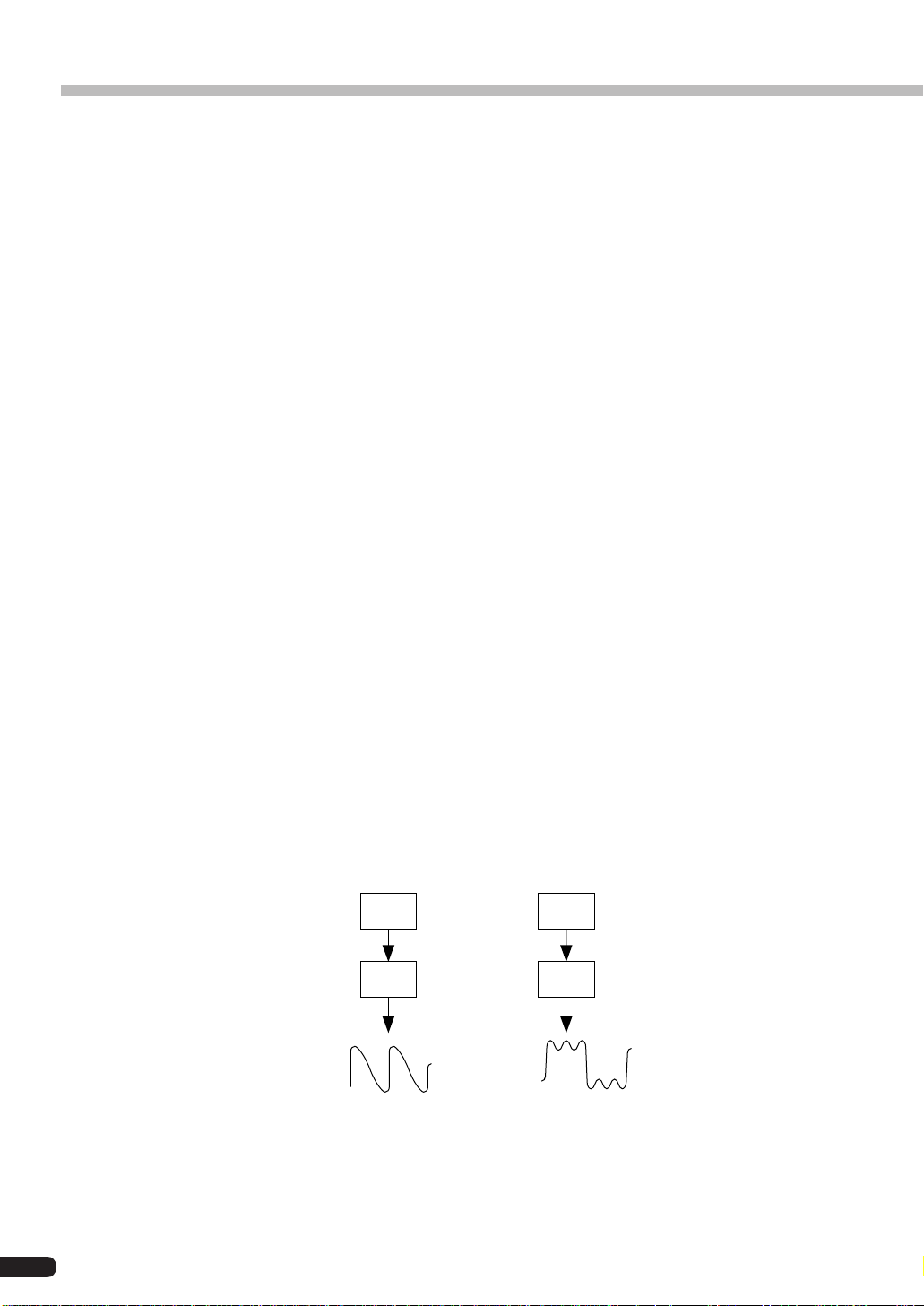
(2) The Frequency of the Tone Output from Each Operator
The type of harmonics added to the carrier output by means of the modulator is determined
by the ratio between the frequencies of the modulator and carrier. For example, when two
operators are combined vertically, and “F COARSE” for both of them is set to 1.00, the
frequency ratio will be 1:1 and the first, second, third and following whole number series
harmonics will be generated in order. This type of harmonic configuration is called a
sawtooth wave, and is used for making voices like brass, strings, or piano.
If the “F COARSE” for the modulation in this situation is changed to 2.00, the frequency
ratio will be 1:2, and the odd numbered harmonics, the first, third and fifth and following
harmonics will be generated. This harmonic configuration is called a rectangular wave,
and is used for creating voices for woodwinds like the clarinet and oboe.
Furthermore, if “F FINE” is used so that the frequency ratio is not a whole number, many
non-integer overtones will be produced. The sound can be used for creating metallic sounds,
the noise when strings are hit with something, or breath noise.
16
Modulator
Carrier
B
Frequency
ratio 1:1
A
Sawtooth wave
B
Frequency
ratio 1:2
A
Rectangular wave
Page 17

FM Tone Generation
(3) FEEDBACK LEVEL
By raising the feedback level, the modulation deepens, and the timbre of the sound becomes brighter.
(4) Envelope Generator (EG)
The EG creates the changes over time in the output level from the instant a key on the
keyboard is pressed to the time that the sound disappears.
If you listen to various musical instruments, you soon realize that besides the differences
in the timbre of the sounds they create, there is a large difference in the way that the sound
first comes out, and in the way in which it fades away. For example, the sound from a
piano gets very loud the instant a key is struck, then the volume gradually fades away, even
if you continue pressing down the key. Also, if you look at the change in tone over time,
there is a bright sound with a lot of overtones the moment the key is struck, but the overtones soon fade away, and the tone takes on a darker aspect.
The function that produces the instrument’s change in volume and timbre over time is the
EG.
In an FM tone generator, an EG is built into each operator. The EG for the carrier changes
its volume over time, while the EG for the modulator changes the timbre of the sound over
time.
17
Page 18

Memory Buffer Configuration
The memory buffer of the PLG100-DX is configured as shown in the diagram below.
Recall
Preset Memory
(912 Voices)
Voice Edit Buffer
Custom Voices
Compare
Store
(64 Voices)
Edit Recall
Edit Recall Buffer
• The only voices that can be edited using an editing program like the DX Simulator are the custom
voices.
When using the custom bank
• The following parameters are not valid when using the custom bank because they are saved as voice
parameters.
XG Native Part Parameters
MONO/POLY MODE
BEND PITCH CONTROL
PORTAMENTO SWITCH
PORTAMENTO TIME
PLG100-DX Native Part Parameters
PitchBend Step
Portamento Step
Portamento Mode
However, MONO/POLY MODE, BEND PITCH CONTROL, PORTAMENTO SWITCH, and
PORTAMENTO TIME are received through CC (Control Change). (When changing to another custom bank voice, that voice will be set to the saved parameters.)
• If an XG System On is received, or part assignment is changed, the custom voices will be initialized, but
the 64 voice VMEM and AMEM areas will not be initialized.
18
Page 19

DX Voice Selection
The PLG100-DX voices can be selected just like the voices for the XG tone generator itself.
However, to use the PLG100-DX voices, XG mode or performance mode (PERFORM) must be
selected in the Sound Module Mode of the XG tone generator. Also the part/performance layer
assigned to the PLG100-DX must be specified in the sub-mode (PLUGIN) of the utility mode of
the XG tone generator.
• The displays used below for explaining tone generator operations are from the MU100. The screens may be
different for the tone generator you are using.
• For tone generators, like the SW1000XG, that have no display, the settings must be sent as System Exclusive
Messages (→ MIDI Data Format).
• The SW1000XG does not support the Performance Mode.
■ Selecting the Voices to be Used .............................................................................
1. Set the Sound Module Mode of the XG tone generator to XG or PERFORM.
When XG is selected, the tone generator will enter Multi Mode.
When PERFORM is selected, the tone generator will enter Performance Play Mode.
• DX voices can be selected only when the Part Mode is set to Normal.
• In XG Mode, DX voices can be used as one part, and in Performance Mode, as one layer.
2. Press the [SELECT / ] buttons, and move the cursor to the bank number.
3. Press the [VALUE / ] buttons and select the bank of the voice you wish to use.
Depending on the bank you have selected, one of the following will appear in the bank
number location of the display: 000,064 to 082, 096 to 109 (DX-XG/A); 000,064 to
082 (DX-XG/B); 000 (DX-XG/SFX) or 000 (Custom).
Bank number display location
Icon display area
DX-XG/A DX-XG/B
DX-XG/SFX
When a DX voice is selected, a DX voice icon will appear in the icon area of the
display.
• Please note that the bank number displayed may be one for the XG tone generator itself. You can make
sure that it is one for the PLG100-DX by checking for a DX voice icon in the icon area of the display.
Custom
4. Press the [SELECT / ] buttons, and move the cursor to the program number.
19
Page 20

DX Voice Selection
5. Use the [VALUE / ] buttons to select the voice you wish to use.
Program number display location
• When a program number that does not exist for the PLG100-DX is selected when the chosen bank is
from 000 to 099, the icon for the voice selected in the XG tone generator itself will be displayed in the
icon area.
■ Specifying Parts/Performance Layers....................................................................
1. Press the [UTIL] button on the panel, and display the utility mode.
2. Press the [SELECT ] button several times to move the cursor to “PLUGIN”, then
press [ENTER].
3. Press the [SELECT / ] buttons as needed to move the cursor to “PLG100-DX,”
then press the [ENTER] button. An editing screen for the system parameters expanded
by the PLG100-DX will be displayed.
4. Press the [SELECT / ] buttons several times to display “PartAssign,” then press
the [VALUE
PLG100-DX.
When the Sound Modulation Mode is XG, use 01 to 16, or off.
When the Sound Modulation Mode is PERFORM, use 01 to 04, or off.
/ ] buttons to select the part or layer you want to assign to the
20
• SW1000XG does not support the performance mode.
Page 21

Editing DX Part Parameters
Editing with the parameters below is valid for voices in all banks. However, they cannot be set
separately for each voice. This means that whatever editing changes you have made will be
transferred as is to the new voice whenever you switch voices (editing done for the previous
voice will be also valid for the next voice chosen).
• When voices are switched after the parameters have been changed, or when the algorithm is changed with the
DX Simulator, unexpected sounds may cause injury to your ears. Always exercise caution when making changes.
• Parameters that have been edited cannot be stored in custom voices.
• When using the DX Simulator, voices can be edited, then stored in custom voices.
1. In Multi Play Mode, choose the part assigned to the PLG100-DX, then select the voice
to be edited.
2. Press the [EDIT] button.
The Multipart edit menu screen will be displayed.
3. Press the [SELECT ] button and move the cursor to “PLUGIN”. Press the [EN-
TER] button.
The parameter screen for the selected plug-in board will be displayed.
4. Press the [SELECT / ] buttons to move the cursor to the parameter to be edited.
Next, change the value for the parameter using the [VALUE
/ ] buttons.
5. Press the [EXIT] button several times to return to the initial screen.
• On the MU100 panel, normal part parameters that can be edited will be valid for DX voices.
21
Page 22

Editing DX Part Parameters
■ PLG100-DX Part Parameters ...................................................................................
Carrier1 (Carrier Operator 1 Level) to Carrier6 (Carrier Operator 6 Level)
Settings: -64 to +63
Explanation:
• Sets the output level for operators that are working as carriers.
• Carriers are operators that work to output the actual sound. Changing the carrier output
level changes the loudness of the sound that is produced. If an algorithm is selected that
has multiple carriers, the quality of the sound, or “timbre” can be edited by changing
the volume balance between the carriers.
• Because this setting acts as an offset added to the output level set for the voice in the
PLG100-DX, it indirectly changes the timbre of the voice. When this parameter is set at
zero, the voice will remain as is. Setting it to +1 or more will increase the volume, while
setting it to -1 or less will decrease it.
• The operators that are assigned as modulators will be displayed as “***”, and it will not
be possible to edit them. To clarify matters when editing voices, look up the algorithm
number for the voice being edited on the voice list, then check which operators have
been assigned as carriers on the Chart of Algorithms (→P. 28).
Modulator1 (Modulator Operator 1 Level) to Modulator6 (Modulator Operator 6 Level)
Settings: -64 to +63
Explanation:
• Sets the output level for operators that are working as modulators.
• Modulators are operators that serve to modulate other operators. Changing the modulator output level changes the brightness (amount of overtones) of the sound that is produced.
• Because this setting acts as an offset added to the output level set for the voice in the
PLG100-DX, it indirectly changes the timbre of the voice. When this parameter is set
to zero, the voice will remain as is. Setting it to +1 or more will make the sound brighter
(increase the overtones), while setting it to -1 or less will darken it (decrease the overtones).
• The operators that are assigned as carriers will be displayed as “***”, and it will not be
possible to edit them. To clarify matters when editing voices, look up the algorithm
number for the voice being edited on the voice list, then check which operators have
been assigned as modulators on the Chart of Algorithms (→P. 28).
22
Page 23

Editing DX Part Parameters
FeedBack
Settings: -7 to +7
Explanation:
• Sets the level of feedback.
• Feedback is a function where a portion of the output of an operator is returned
back to the operator again, where it is used to modulate the operator itself. Feedback can be used to change the brightness (amount of overtones) of the sound.
• Because this setting acts as an offset added to the output level set for the voice in
the PLG100-DX, it indirectly changes the timbre of the voice. When this parameter is set to zero, the voice will remain as is. Setting it to +1 or more will make the
sound brighter (increase the overtones), while setting it to -1 or less will darken it
(decrease the overtones).
PortaMd (Portamento Mode)
Settings: flw/ftm, rtn/fgr
Explanation:
• Portamento is an effect that produces a smooth glide between two notes of different pitch.
• The way in which the Portamento effect is applied is set with the Portamento
Mode. However, there will be a large difference in the effect depending on the
Poly/Mono setting for the selected voice.
When Poly Mode is set:
• When flw/ftm is set, the Portamento effect will also be applied to the sustained
sound from when the sustain pedal is depressed, and to the lingering sound after
the hand is removed from the key. The sound will change to the pitch of the next
note played.
• When rtn/fgr is set, the Portamento effect will not be applied to the sustained
sound from when the sustain pedal is depressed, or to the lingering sound after the
hand is removed from the key.
When Mono Mode is set:
• When flw/ftm is set, normal Portamento effect is applied.
• When rtn/fgr is set, the Portamento effect is only applied when the next key is
pressed while the first key is held down.
• In the DX7, each is called as follows:
flw: Sus-key P Follow
ftm: Full Time Porta
rtn: Sus-key P Retain
fgr: Fingered Porta
PortaStep (Portamento Step)
Settings: 0 to 12
Explanation:
• Sets the way in which the pitch is changed by the Portamento effect.
• The 0 value sets a normal continuous change.
• Setting 1 to 12 changes sound according to the scale. For example, if 1 is set, the
change is by semitones, if 2 is set, it is by whole tones.
23
Page 24

Editing DX Part Parameters
PitBndStep (Pitch Bend Step)
Setting Values : 0 to 12
Explanation:
• Determines the way in which the pitch is changed by the pitch bend wheel.
• The 0 value sets a continuous change (the normal setting). Setting 1 to 12 changes the
sound according to the scale. For example, if 1 is set, the change is by semitones, if 2 is
set, it is by whole tones.
AC4 CC No. (AC4 Controller Assign)
Settings: OFF, MOD, BC, FC, EXP, CAT, PB
Explanation:
• When the AC4 controller parameter is set to EGbias, this parameter sets the controller
which operates EGbias.
• The settings indicate controllers as follows:
MOD ..... Modulation wheel
BC......... Breath controller
FC ......... Foot controller
EXP....... Expression pedal
CAT....... Channel aftertouch
PB ......... Pitch bend wheel
• When the amplitude modulation sensitivity of the selected voice has been set to carrier,
operating the controller that has been set in this parameter will change the volume in
realtime. When the amplitude modulation sensitivity has been set to modulator, the
timbre will change.
AC4CtrPrm1 (AC4 Controller Parameter 1)
Settings: Off, EGbias
Explanation:
This specifies whether the EGbias will be controlled by the controller that has been set
in the AC4 Control Change Number parameter.
AC4CtrDpt1 (AC4 Controller Parameter Depth)
Setting: -64 to +63
Explanation:
Specifies the depth of operation when EGbias is controlled by the controller that has
been set in the AC4 Control Change Number parameter.
• When AC4CtrPrm1 has been set to EGbias, the sound may change when AC4CtrDept1 is set positive, even
if the output from the controller set in AC4CCNo.is zero.
24
Page 25

Editing DX Part Parameters
RcvDxSysEx (Receive DX System Exclusive)
Setting: OFF, ON
Explanation:
Specifies whether DX system exclusive messages will be received or not.
• The follow conditions must be met for DX system exclusive messages to be received:
With VCED, ACED (Parameter change, Bulk Dump)
With VMEM, AMEM: (bulk dump, 32 voice bulk dump)
Bulk select: Custom Bank
RcvDxSysEx: ON
RcvDxSysEx: ON
25
Page 26

PLG100-DX System Parameters
The parameters that apply to the entire system of the PLG100-DX are added to the utilities of the
main XG tone generator.
1. Press the [UTIL] button.
The menu screen for the Utility Mode will be displayed.
2. Pressing the [SELECT ] button and move the cursor to “PLUGIN,” then press the
[ENTER] button. The plug-in board select screen will be displayed.
3. Press the [SELECT / ] buttons and move the cursor to the plug-in board to be
edited, then press the [ENTER] button (select PLG100-DX here).
The parameter screen for the selected plug-in board will be displayed.
4. Pressing the [SELECT / ] buttons, move the cursor to the parameter which is to
be set. Change the value for the parameter using the [VALUE
/ ] buttons.
5. Press the [EXIT] button several times to return to the initial screen.
26
Page 27

PLG100-DX System Parameters
■ System Parameters ..................................................................................................
PartAssign
Setting: 1 to 16, OFF
Explanation:
• Sets the part assigned to PLG100-DX.
• When set to OFF, the parts will not be assigned. Settings 1 to 16 specify part numbers
1 to 16.
BulkBlock
Setting: 01-32, 33-64
Explanation:
• Specifies which custom voice memory, 1 to 32 or 33 to 64, will be used for writing 32
voice bulk data sent to the PLG100-DX from an external MIDI device or computer.
VelCurve (Velocity Curve)
Setting: DX7, Normal, Soft1, Soft2, Easy, Wide, Hard
Explanation:
• Sets the velocity curve.
• The velocity curve is the curve that expresses the relationship between the velocity
signal received and the volume when the sound is actually generated.
• DX7 sets the velocity curve for the DX7 and DX7II.
• Normal makes velocity proportional to the strength at which the key is struck. This is
the velocity curve used in ordinary synthesizers.
• Soft1 is a velocity curve that makes all sounds easy to produce. It is designed for people
who have a light touch on the keyboard, or who are beginners at keyboard playing.
• Soft2 is a velocity curve that makes all sounds easy to produce. It is closer to the normal
curve than Soft1.
• Easy is a velocity curve where relatively large velocities are easy to produce. Because
velocity change in the middle area of the curve is gentle, the velocity is stable.
• Wide is a curve where the velocity is controlled in sections where the key touch is light,
and is easy to produce in area where the touch is strong. It gives the feeling of a wide
dynamic range.
• Hard is a curve where the sound is not easy to produce over the entire range. It is aimed
a people who have a strong touch.
27
Page 28

Appendix
Chart of Algorithms
123
6
5
4
2
3
1
1
3
6
2
5
1
4
4
6
4
5
12345
123
6
3
5
4
2
3
1
2
6
12345
5
6
5
4
2
1
6
2
5
1
4
3
6
6
6
5
4
3
28
7
3
65
2
4
1
10
4
5
3
13
2
6
1
56
8
4
11
5
123
14
9
3
2
1
6
4
45
6
3
12
56
234
1
15
2
1
Page 29

Appendix
6
2
123
456
3
1
16
236
1
19
22
4 5
6
4
46
1
17
5
20
234
23
5
6
4
6
5
23
3
12
5
1
2534
1
18
6
1
2345
21
23
1
24
6
4
5
12
2
1
12
25
5
4
3
28
3
31
6
4
3
6
6
45
3
5
12
12
12
26
29
3
32
6
5
4
4
6
35
45
6
21
27
5
4
123
30
6345
6
29
Page 30

Appendix
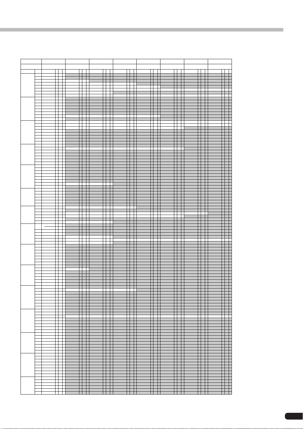
Voice List
DX-XG/SFX Voices
Bank Select MSB 67
Bank Select LSB 0
Instrument
Group
SFX 1
Pgm #
(1-128)
17
18
19
20
21
33
34
49
50
51
52
53
54
55
56
65
66
67
68
69
70
71
72
73
74
81
82
83
84
85
86
87
88
89
90
91
92
97
98
99
100
101
102
103
104
105
113
114
115
116
117
118
119
120
121
122
123
124
125
126
127
128
EA
Turn Tbl 1 18
DX-Clave 1 6
SideStck 1 17
Snapie 1 2
Deep Snr 1 2
SumohDrm 1 3
DX-Wave 1 17
Image 3 1 17
DX-Piyo1 1 0
DX-Inct1 1 16
DX-Grwl1 1 2
DX-Grwl2 1 18
Help me! 1 17
DX-Wolf 1 6
JnglBell 1 5 *
DX-Inct2 1 3 *
DX-Ring1 1 23 *
DX-TlCal 1 5 *
DX-TlBsy 1 23 *
DX-TlTne 1 12
DX-Ring2 1 3 *
DX-BigBn 1 6
IronEch1 1 5
IronEch2 1 5
DX-RvCy1 1 5 *
DX-RvCy2 1 17 *
DX-Hlcpt 1 5
DX-Train 1 5 *
Take Off 1 10
Mobile 1 1 18
MotrCycl 1 18
DX-Ship 1 18
Closing 1 5 *
Scrchers 1 17
MM-Fall 1 18
DX-Flght 1 18 *
MobyDick 1 12 *
OutLimit 1 5 *
Paranoir 1 17 *
CaGhstLn 1 0
MM-Shk 2 1 1
Image 1 1 0
Image 2 1 1
Tenjiku 1 0
Metal 1 1
Flxatone 1 0
Spoon 1 1
WhikShot 1 18 *
PercShot 1 17
Crasher 1 18 *
Laser 1 1 16
Laser 2 1 16
Laser 3 1 1
Stopper 1 16 *
Wallop 1 1 16
Wallop 2 1 16
StreetSD 1 4 *
ManEater 1 2 *
SmbaWhsl 1 18
Refs Wsl 1 18
Triangl1 1 23
Triangl2 1 23
SlighBel 1 18
DX-XG/A Voices
B
Bank Select MSB
Bank Select LSB
Instrument
Pgm #
Group
(1-128)
Piano 1
Chromatic 9
Percussion 10
Organ 17
Guitar 25
Bass 33
Strings 41
Ensemble 49
Brass 57
Reed 65
Pipe 73
Synth 81
Lead 82
Synth Pad 89
Synth 98
Effects 99
Ethnic 105
Percussive 113
FrtePno1 1 9
2
BritPno1 1 7
3
DXCP-70 1 4
4
DX-Rgtim 1 15
5
DX-Road1 1 28
6
E.Pno 1 1 5
7
Harpsi 1 1 5
8
MM-Clav1 1 4
Celesta1 1 31
Glocken1 1 23
11
MusicBx1 1 5
12
DX-Vibe1 1 27
13
DX-Mrmb1 1 7
14
DX-Xylo1 1 9
15
Carillon 1 9
16
DX-Dlcm1 1 10
FullOrgn 1 32 *
18
PrcOrg 1 1 29 *
19
RckOrg 1 1 3 *
20
DXChrch1 1 6
21
PufOrgn1 1 12 *
22
DX-Acrd1 1 3 *
23
DX-Hmnc1 1 3 *
24
DX-TngAc 1 3
DX-AcGt1 1 14
26
DX-PkGt1 1 14
27
DX-JzGt1 1 18
28
DX-ClGt1 1 9
29
DX-MtGt1 1 9
30
DX-ODGt 1 14
31
Fuzz Gtr 1 1
DX-WdBa1 1 17
34
DX-FgBa1 1 16
35
DX-PkBa1 1 16
36
FrtlsBa1 1 17
37
RundWund 1 18
38
DigiBas1 1 16
39
DX-SyBa1 1 16 *
40
DX-Bass1 1 17
DX-Vln 1 1 2 *
42
DX-Vla 1 1 15
43
DX-Celo1 1 2
46
DX-Pizz1 1 2
47
LuteHarp 1 14
48
DX-Tmpni 1 16
Mid Str1 1 15
50
WarmStr1 1 15
51
DX-SySt1 1 15
52
DX-SySt6 1 2
53
DX-Cho 1 1 5 *
55
DX-Cho 6 1 11 *
DX-Trpt1 1 18 *
58
DX-Trb 1 1 18 *
59
DX-Tuba1 1 18 *
61
DX-Horn 1 9
62
DX-BrSc1 1 22
63
CS80-Br1 1 23 *
64
ChorsBrs 1 2
SprnoSax 1 10 *
66
Alto Sax 1 18 *
67
TenorSax 1 27 *
69
Oboe 1 1 3 *
70
Eng.Horn 1 4 *
71
Bassoon 1 2
72
VbrtClar 1 5 *
Piccolo1 1 5
74
DX-Flt 1 1 16 *
75
Recordr1 1 5
76
DX-PnFl1 1 5
77
Fuhppps! 1 11 *
79
Whistle1 1 16 *
80
DX-Ocrn1 1 14 *
DX-Squar 1 2
DXSyLd 1 1 18
83
CaliopL1 1 16
84
BrsLead1 1 2
85
Au Campo 1 2 *
86
DX-VceLd 1 18
87
Fifths 1 1 3
88
LeadLine 1 18
HyperSqr 1 5 *
90
Film Pad 1 16
91
BritePad 1 15
92
DX-ChPd1 1 15 *
93
BowPad 1 1 5 *
94
DX-MtPd1 1 6 *
95
GrngePad 1 15
96
SweepPd1 1 9 *
FluvPush 1 1
MtalGlkn 1 5
100
PrdsGlok 1 5
101
DX-Brit1 1 5
102
Fmilters 1 11 *
103
WaterLog 1 16 *
104
DX-ScFi1 1 6 *
DX-Sitr1 1 8
106
DX-Banjo 1 8
107
Shamisn1 1 16
108
DX-Koto 1 2
109
DX-Klmb1 1 30 *
110
DX-BgPip 1 20 *
111
DX-Fidle 1 2
112
ScchTone 1 17
HandBel1 1 5
114
DX-Aggo1 1 8
115
StlDrum1 1 5
116
Block 1 18
117
Janpany 1 16
119
MM-SDr 1 1 18 *
0
E
8383
64
EBABA
FrtePno2 1 18
BritPno2 1 18
El.Gnd 1 1 16 *
ToyPno 1 1 30 *
BigWurlt 1 17 *
ClrE.Pno 1 5 *
Cembalim 1 5
MM-Clav2 1 3
Celesta2 1 32
Glocken2 1 32
MM-Vibe1 1 23
BritMrmb 1 7
DX-Xylo2 1 5
DX-Bel 1 1 27
DrwOrg 1 1 32 *
PrcOrg 2 1 18
RckOrg 2 1 5
PipeOrg1 1 3
SoftRdOr 1 28
DX-Acrd2 1 3
DX-Hmnc2 1 1 *
DX-AcGt2 1 8
DX-PkGt2 1 14
DX-JzGt2 1 17
DX-ClGt2 1 14
DX-MtGt2 1 12
DX-DsGt1 1 16
DX-WdBa2 1 17
DX-FgBa2 1 17
PickPluk 1 18
FrtlsBa2 1 18
SlapStrg 1 4 *
SuprBas1 1 17
DX-SyBa2 1 3
Remark 1 17
DX-Vln 2 1 2
DX-Vla 2 1 17 *
Rosin 1 18 *
Pizz Str 1 5
Syn Harp 1 3
Mid Str2 1 15
Low Str1 1 15
Anna Str 1 9 *
DX-SySt7 1 4 *
DX-Cho 2 1 6
DX-Cho 7 1 7 *
DX-Trpt2 1 18 *
DX-Trb 2 1 22
DX-Tuba2 1 18 *
MelwHrn1 1 2 *
DX-BrSc2 1 22
CS80-Br2 1 22 *
SyntiBrs 1 2
DX-Tsax 1 15 *
Oboe 2 1 3
SlowClar 1 4
Piccolo2 1 5 *
DX-Flt 2 1 7
Recordr2 1 6 *
Forest99 1 2
DX-Botle 1 15
DX-Ocrn2 1 4
DX-SLd 1 1 5
DXSyLd 2 1 9
CaliopL2 1 16 *
DX-WahLd 1 7
LeadPhon 1 19
Giovanni 1 6
Fifths 2 1 1
BassLead 1 22
Cho+Mrmb 1 14
DX-SawPd 1 15
SyBr Pd1 1 12 *
Anna Pad 1 2 *
BowPad 2 1 5 *
InitEnsm 1 6
StacHevn 1 9
Evlution 1 1 *
BellPluk 1 11
Brassy 1 2
DX-Brit2 1 6
DX-ScFi2 1 16
DX-Sitr2 1 3
Shamisn2 1 22
Koto+Flt 1 2
DX-Klmb2 1 18
HandBel2 1 5
DX-Aggo2 1 15
StlDrum2 1 13
SoftHead 1 15 *
MM-SDr 2 1 18 *
83 83 83 83 83 83
65
EBA
MM-Pno 1 1 19
BritPno3 1 3
El.Gnd 2 1 4
ToyPno 2 1 9
WurliEP1 1 3 *
E.Pno 2 1 5
AD1600s1 1 3 *
SkltnClv 1 18
Celesta3 1 5
Glocken3 1 7
DX-Vibe2 1 23
DX-Mrmb2 1 7
MM-Bell 1 27
DrwOrg 2 1 29
PrcOrg 3 1 29
RckOrg 3 1 16
PipeOrg2 1 29
PufOrgn2 1 12 *
DX-Acrd3 1 4 *
BuzzHarp 1 17 *
DX-AcGt3 1 1
DX-PkGt3 1 2
DX-JzGt3 1 8 *
DX-ClGt3 1 4
DX-MtGt3 1 17
DX-DsGt2 1 14
DX-WdBa3 1 3
HarmBass 1 17
ChifBass 1 7 *
FrtlsBa3 1 12
LiteSlap 1 3
DrhtBass 1 16
DX-SyBa3 1 24
DX-Bass2 1 17 *
DX-Vln 3 1 2
DX-Celo2 1 11
OrchHarp 1 3 *
Brit Str 1 15
Low Str2 1 2
SmalSect 1 15 *
DX-AnSt3 1 15
DX-Cho 3 1 24
DX-Cho 8 1 29 *
DX-Trpt3 1 18 *
Mute Trb 1 7
MelwHrn2 1 3 *
5th Brss 1 2
DX-SBr 1 1 22
DX-SBr 7 1 18
Oboe 3 1 27
DX-Clar1 1 2 *
DX-Flt 3 1 16 *
Recordr3 1 6 *
Harvest 1 1 *
Quena 1 2
DX-Ocrn3 1 3
DX-SLd 2 1 22
DXSyLd 3 1 24
PuffPipe 1 12
BrsLead2 1 2
SweepLd 1 18
SnglLine 1 22
EadgbeLd 1 14
IceHeven 1 9
ElecComb 1 4 *
SyBr Pd2 1 5 *
Whisper1 1 6 *
BowPad 3 1 7 *
MtlSweep 1 9 *
Phasers 1 15 *
MtalDlcm 1 27
Electric 1 4
SynBrite 1 3
Baroque 1 15
JuceHarp 1 18
Shamisn3 1 15
DX-Klmb3 1 16
TrcrBell 1 4
Jamaica 1 16
Tom Herz 1 18
66
EBA
Digi Pno 1 16
5th Pno1 1 5
El.Gnd 3 1 11
ToyPno 3 1 3
EP 1980 1 17 *
Urban 1 7
AD1600s2 1 3
ClavStf1 1 18
Glocken4 1 24
DX-Vibe3 1 5
DX-Mrmb3 1 7
MiniBell 1 5
DrwOrg 3 1 29
DxJazOr1 1 30
RckOrg 4 1 11 *
DXChrch2 1 6
StretOrg 1 16
DX-Acrd4 1 4 *
FM-Hmnc1 1 1 *
DX-AcGt4 1 8
DX-PkGt4 1 3
DX-JzGt4 1 8
DX-ClGt4 1 13
DX-MtGt4 1 3
DX-DsGt3 1 16
SmohBass 1 17
NstyBass 1 17
Plktrmbs 1 8
FrtlsBa4 1 18
ImpctBas 1 16
Brainacs 1 7
Cutmandu 1 8
DX-Bass3 1 17
DX-Celo3 1 11
Harp+Flt 1 3 *
DX-Str 1 1 2
DX-Str10 1 5
Michelle 1 15
MM-Str 1 1 17
DX-Cho 4 1 4
MM-Vce 1 1 7 *
DX-Trpt4 1 18 *
MletHorn 1 18
TightBr1 1 2
DX-SBr 2 1 22 *
SamplBrs 1 2
DX-Clar2 1 15 *
DX-Flt 4 1 5 *
LyleLead 1 3
Super DX 1 4
CaliopL3 1 16 *
BrsLead3 1 15
LdSbHarm 1 26 *
DX-Ba+Ld 1 2
MM-Prety 1 3
Fl.Cloud 1 5
SyBr Pd3 1 15
Ethereal 1 5
Gior Pad 1 19
FM-Grwth 1 17
MetalBox 1 11
DX-Atms1 1 15
DX-ScFi3 1 15 *
Xanu 1 4
SteelCan 1 1
67
EBA
MM-EGnd1 1 19
ToyPno 4 1 12
DX-Road2 1 12
E.Pno 3 1 5
Harpsi 2 1 5
Revinett 1 18
DX-Vibe4 1 7
MtalMrmb 1 6
DX-Bel 2 1 15
JazOrg 1 1 32
PrcOrg 4 1 29 *
RckOrg 5 1 26 *
PipeOrg3 1 6
DX-Acrd5 1 3 *
FM-Hmnc2 1 3 *
Lute Gtr 1 14
DX-PkGt5 1 8
DX-ClGt5 1 3
HevyGage 1 18
DX-DsGt4 1 16
After 88 1 17 *
FustBass 1 18
Owl Bass 1 4
FrtlsBa5 1 3
Afresh 1 3
DigiBas2 1 16
DX-SyBa4 1 9
Hop Bass 1 16
DX-Str 2 1 2
DX-Str11 1 2
DX-SySt2 1 25
WarmStr3 1 15 *
DX-Cho 5 1 6
MM-Vce 2 1 6 *
SlvTrmpt 1 18
BlnchHrn 1 2
TightBr2 1 22
DX-SBr 3 1 5
SinglBrs 1 22
DX-Flt 5 1 16 *
DX-SLd 3 1 6
DXSyLd 4 1 2
DXAtkLd 1 16
FrtlsLd 1 4
TngVoice 1 17
Floating 1 19 *
SyBr Pd4 1 2
Glassy 1 11
DX-Atms2 1 8
DX-Stars 1 23
EthrFour 1 5
68
EBA
MM-EGnd2 1 19
PrprdPno 1 9 *
DX-Road3 1 12
Vics EP 1 11 *
Harpsi 3 1 3
Clavecn1 1 2
BellVibe 1 23
DX-Bel 3 1 5
Farf Out 1 29 *
PrcOrg 5 1 31 *
RckOrg 6 1 16
PipeOrg4 1 5 *
DX-AcGt5 1 16
DX-PkGt6 1 14
DX-ClGt6 1 17
DX-DsGt5 1 1
DX-WdBa4 1 22
ClavBass 1 10
MtalBass 1 4
BassNovo 1 7 *
Excite 1 17
DX-Str 3 1 15
DX-Str12 1 15 *
DX-SySt3 1 25
WarmStr4 1 15 *
MM-Vce 3 1 6 *
AlpsHorn 1 15 *
BlowBrss 1 9 *
DX-SBr 4 1 2 *
ThickBrs 1 2
DX-Flt 6 1 16 *
DX-SLd 4 1 18
DXSyLd 5 1 5 *
Str Tine 1 12
BrsyWarm 1 15 *
SyBr Pd5 1 4
GlssHarp 1 16
NOTE : Empty areas of the columns produce no sound.
E : Element number A : Algorithm number B : EG Bias (voices with this effect are marked “*”)
69
EBA
DigiPoly 1 5
Bell Pno 1 5
Old Jazz 1 5
E.Pno 4 1 5
Harpsi 4 1 18
E.P/Clav 1 11
LFO Vibe 1 2 *
DX-Bel 4 1 9
DrwOrg 4 1 31
PrcOrg 6 1 31
RckOrg 7 1 22 *
PipeOrg5 1 5
Mrmb Gtr 1 12
DX-PkGt7 1 3
DX-ClGt7 1 3
DX-WdBa5 1 17
DX-FgBa3 1 17 *
WireBass 1 10
DX-SyBa5 1 3
DX-Bass4 1 18
DX-Str 4 1 15
DX-Str13 1 2
DX-SySt4 1 9 *
HalOrch1 1 12
Dbvoxfem 1 26 *
VibraHrn 1 17 *
BrssSect 1 2
DX-SBr 5 1 2
XyloBrss 1 29 *
DX-Flt 7 1 16 *
DX-SLd 5 1 6
DXSyLd 6 1 1
WhstlPad 1 25 *
SyBr Pd6 1 19
Ice Glxy 1 3
70
EBA
Mark III 1 10 *
Andrian 1 9
Knock EP 1 13
E.Pno 5 1 5
Caffeine 1 9
DX-Clv 1 1 18
Vibetron 1 6 *
DX-Bel 5 1 4
DrwOrg 5 1 32
PrcOrg 7 1 20 *
RckOrg 8 1 25
Tite Gtr 1 15
DX-ClGt8 1 3
Inorganc 1 3
DX-SyBa6 1 3
DX-Str 5 1 2
DX-AnSt1 1 2
HalOrch2 1 12
Lady Vox 1 26
WarmBrss 1 9 *
DX-SBr 6 1 22
OrchBrss 1 2
MtalFlut 1 2 *
DX-SLd 6 1 2
DXSyLd 7 1 18
SyBr Pd7 1 2
SpceTrip 1 23
30
Page 31
Appendix
Bank Select MSB
Bank Select LSB
Instrument
Pgm #
Group
(1-128)
Piano 1
Chromatic 9
Percussion 10
Organ 17
Guitar 25
Bass 33
Strings 41
Ensemble 49
Brass 57
Reed 65
Pipe 73
Synth 81
Lead 82
Synth Pad 89
Synth 98
Effects 99
Ethnic 105
Percussive 113
FrtePno1 1 9
2
BritPno1 1 7
3
DXCP-70 1 4
4
DX-Rgtim 1 15
5
DX-Road1 1 28
6
E.Pno 1 1 5
7
Harpsi 1 1 5
8
MM-Clav1 1 4
Celesta1 1 31
Glocken1 1 23
11
MusicBx1 1 5
12
DX-Vibe1 1 27
13
DX-Mrmb1 1 7
14
DX-Xylo1 1 9
15
Carillon 1 9
16
DX-Dlcm1 1 10
FullOrgn 1 32 *
18
PrcOrg 1 1 29 *
19
RckOrg 1 1 3 *
20
DXChrch1 1 6
21
PufOrgn1 1 12 *
22
DX-Acrd1 1 3 *
23
DX-Hmnc1 1 3 *
24
DX-TngAc 1 3
DX-AcGt1 1 14
26
DX-PkGt1 1 14
27
DX-JzGt1 1 18
28
DX-ClGt1 1 9
29
DX-MtGt1 1 9
30
DX-ODGt 1 14
31
Fuzz Gtr 1 1
DX-WdBa1 1 17
34
DX-FgBa1 1 16
35
DX-PkBa1 1 16
36
FrtlsBa1 1 17
37
RundWund 1 18
38
DigiBas1 1 16
39
DX-SyBa1 1 16 *
40
DX-Bass1 1 17
DX-Vln 1 1 2 *
42
DX-Vla 1 1 15
43
DX-Celo1 1 2
46
DX-Pizz1 1 2
47
LuteHarp 1 14
48
DX-Tmpni 1 16
Mid Str1 1 15
50
WarmStr1 1 15
51
DX-SySt1 1 15
52
DX-SySt6 1 2
53
DX-Cho 1 1 5 *
55
DX-Cho 6 1 11 *
DX-Trpt1 1 18 *
58
DX-Trb 1 1 18 *
59
DX-Tuba1 1 18 *
61
DX-Horn 1 9
62
DX-BrSc1 1 22
63
CS80-Br1 1 23 *
64
ChorsBrs 1 2
SprnoSax 1 10 *
66
Alto Sax 1 18 *
67
TenorSax 1 27 *
69
Oboe 1 1 3 *
70
Eng.Horn 1 4 *
71
Bassoon 1 2
72
VbrtClar 1 5 *
Piccolo1 1 5
74
DX-Flt 1 1 16 *
75
Recordr1 1 5
76
DX-PnFl1 1 5
77
Fuhppps! 1 11 *
79
Whistle1 1 16 *
80
DX-Ocrn1 1 14 *
DX-Squar 1 2
DXSyLd 1 1 18
83
CaliopL1 1 16
84
BrsLead1 1 2
85
Au Campo 1 2 *
86
DX-VceLd 1 18
87
Fifths 1 1 3
88
LeadLine 1 18
HyperSqr 1 5 *
90
Film Pad 1 16
91
BritePad 1 15
92
DX-ChPd1 1 15 *
93
BowPad 1 1 5 *
94
DX-MtPd1 1 6 *
95
GrngePad 1 15
96
SweepPd1 1 9 *
FluvPush 1 1
MtalGlkn 1 5
100
PrdsGlok 1 5
101
DX-Brit1 1 5
102
Fmilters 1 11 *
103
WaterLog 1 16 *
104
DX-ScFi1 1 6 *
DX-Sitr1 1 8
106
DX-Banjo 1 8
107
Shamisn1 1 16
108
DX-Koto 1 2
109
DX-Klmb1 1 30 *
110
DX-BgPip 1 20 *
111
DX-Fidle 1 2
112
ScchTone 1 17
HandBel1 1 5
114
DX-Aggo1 1 8
115
StlDrum1 1 5
116
Block 1 18
117
Janpany 1 16
119
MM-SDr 1 1 18 *
0
E
8383
71
EBABA
RatioDob 1 5
SftEPno1 1 5
EP 1970 1 11 *
FulTine1 1 5
HarpsiWr 1 2
ClavComp 1 15
DX-Bel 6 1 5
DrwOrg 6 1 29
PrcOrg 8 1 31
RckOrg 9 1 22
Gtr Box 1 15
DX-SyBa7 1 17
DX-Str 6 1 2
DX-AnSt2 1 2
Maxi Str 1 2
SpaceVox 1 26
Horn Ens 1 20 *
MM-Brss1 1 18
Ensemble 1 9 *
AirBlowr 1 16 *
Vibratrn 1 4
ClaviPad 1 8
83 83 83 83 83 83
72
EBA
SftEPno2 1 5
DX-Road4 1 12
Duke EP 1 5
Harpsi 5 1 5
DX-Clv 2 1 3 *
TmplBel1 1 5
DrwOrg 7 1 29
PrcOrg 9 1 32
RckOrg10 1 32 *
LongNail 1 16
DX-SyBa8 1 5
DX-Str 7 1 2
AgtateMs 1 2 *
SilkHall 1 5
Syn Vox 1 25 *
Fanfare 1 18
MM-Brss2 1 18
Kingdom 1 15 *
DXSyLd 8 1 22
Dspo Pad 1 4
73
EBA
GlockPno 1 3 *
PrcEPno1 1 5
E.Pno 6 1 5
DX-Clv 3 1 18
TmplBel2 1 11
DrwOrg 8 1 32
PrcOrg10 1 31 *
RckOrg11 1 29
Firenze 1 3
DX-Str 8 1 22
SolinePf 1 2
Aftrnoon 1 2
MM-Brss3 1 17
Winwood 1 2
FnerThng 1 11
74
EBA
ModEPno1 1 5 *
E.Pno 7 1 5
ClavExcl 1 17
TmplBel3 1 11
DrwOrg 9 1 29
PrcOrg11 1 31 *
RckOrg12 1 29 *
Folknik 1 18
Soft Bow 1 2
ST.Machn 1 3
Funkrhyt 1 3 *
MnstrPad 1 15
75
EBA
FulTine2 1 5
BritClv1 1 18
DrwOrg10 1 24 *
PrcOrg12 1 22
SynOrg 2 1 22
RytmPluk 1 17
GntlMind 1 9
MoterDrv 1 2
PowerDrv 1 23
WhaserPd 1 15
76
E.Pno 8 1 6
BritClv2 1 4 *
DrwOrg11 1 32 *
PrcOrg13 1 22 *
Gypsy 1 18 *
RahlBrss 1 23 *
BackSuir 1 2
EBA
NOTE : Empty areas of the columns produce no sound.
E : Element number A : Algorithm number B : EG Bias (voices with this effect are marked “*”)
77
EBA
E.Pno 9 1 5
DX-Clv 4 1 3
DrwOrg12 1 25
PrcOrg14 1 16
UltraDrv 1 2
PsrSweep 1 8
31
Page 32

Appendix
Bank Select MSB
Bank Select LSB
Instrument
Group
Piano 1
Chromatic 9
Percussion 10
Organ 17
Guitar 25
Bass 33
Strings 41
Ensemble 49
Brass 57
Reed 65
Pipe 73
Synth 81
Lead 82
Synth Pad 89
Synth 98
Effects 99
Ethnic 105
Percussive 113
Pgm #
(1-128)
FrtePno1 1 9
2
BritPno1 1 7
3
DXCP-70 1 4
4
DX-Rgtim 1 15
5
DX-Road1 1 28
6
E.Pno 1 1 5
7
Harpsi 1 1 5
8
MM-Clav1 1 4
Celesta1 1 31
Glocken1 1 23
11
MusicBx1 1 5
12
DX-Vibe1 1 27
13
DX-Mrmb1 1 7
14
DX-Xylo1 1 9
15
Carillon 1 9
16
DX-Dlcm1 1 10
FullOrgn 1 32 *
18
PrcOrg 1 1 29 *
19
RckOrg 1 1 3 *
20
DXChrch1 1 6
21
PufOrgn1 1 12 *
22
DX-Acrd1 1 3 *
23
DX-Hmnc1 1 3 *
24
DX-TngAc 1 3
DX-AcGt1 1 14
26
DX-PkGt1 1 14
27
DX-JzGt1 1 18
28
DX-ClGt1 1 9
29
DX-MtGt1 1 9
30
DX-ODGt 1 14
31
Fuzz Gtr 1 1
DX-WdBa1 1 17
34
DX-FgBa1 1 16
35
DX-PkBa1 1 16
36
FrtlsBa1 1 17
37
RundWund 1 18
38
DigiBas1 1 16
39
DX-SyBa1 1 16 *
40
DX-Bass1 1 17
DX-Vln 1 1 2 *
42
DX-Vla 1 1 15
43
DX-Celo1 1 2
46
DX-Pizz1 1 2
47
LuteHarp 1 14
48
DX-Tmpni 1 16
Mid Str1 1 15
50
WarmStr1 1 15
51
DX-SySt1 1 15
52
DX-SySt6 1 2
53
DX-Cho 1 1 5 *
55
DX-Cho 6 1 11 *
DX-Trpt1 1 18 *
58
DX-Trb 1 1 18 *
59
DX-Tuba1 1 18 *
61
DX-Horn 1 9
62
DX-BrSc1 1 22
63
CS80-Br1 1 23 *
64
ChorsBrs 1 2
SprnoSax 1 10 *
66
Alto Sax 1 18 *
67
TenorSax 1 27 *
69
Oboe 1 1 3 *
70
Eng.Horn 1 4 *
71
Bassoon 1 2
72
VbrtClar 1 5 *
Piccolo1 1 5
74
DX-Flt 1 1 16 *
75
Recordr1 1 5
76
DX-PnFl1 1 5
77
Fuhppps! 1 11 *
79
Whistle1 1 16 *
80
DX-Ocrn1 1 14 *
DX-Squar 1 2
DXSyLd 1 1 18
83
CaliopL1 1 16
84
BrsLead1 1 2
85
Au Campo 1 2 *
86
DX-VceLd 1 18
87
Fifths 1 1 3
88
LeadLine 1 18
HyperSqr 1 5 *
90
Film Pad 1 16
91
BritePad 1 15
92
DX-ChPd1 1 15 *
93
BowPad 1 1 5 *
94
DX-MtPd1 1 6 *
95
GrngePad 1 15
96
SweepPd1 1 9 *
FluvPush 1 1
MtalGlkn 1 5
100
PrdsGlok 1 5
101
DX-Brit1 1 5
102
Fmilters 1 11 *
103
WaterLog 1 16 *
104
DX-ScFi1 1 6 *
DX-Sitr1 1 8
106
DX-Banjo 1 8
107
Shamisn1 1 16
108
DX-Koto 1 2
109
DX-Klmb1 1 30 *
110
DX-BgPip 1 20 *
111
DX-Fidle 1 2
112
ScchTone 1 17
HandBel1 1 5
114
DX-Aggo1 1 8
115
StlDrum1 1 5
116
Block 1 18
117
Janpany 1 16
119
MM-SDr 1 1 18 *
83
0
E
BA
E.Pno10 1 5
DX-Clv 5 1 16
SynOrg 1 1 28
Ana Poly 1 22
83 83
78
EBA
Court 1 22
79
EBA
83 83 83 83 83
80
EBA
Juice 1 20
96
EBA
MM-Pno 2 1 19
PowerPno 1 3
El.Gnd 4 1 17
Soft EP1 1 5
DynoRoad 1 5
Harpsi 6 1 5 *
MM-Clav3 1 3
Celesta4 1 23
Glocken5 1 5 *
MusicBx2 1 5
MM-Vibe2 1 23
DX-Mrmb4 1 7 *
DX-Xylo3 1 7
DX-Bel 7 1 5
SilkRoad 1 10
DrwOrg13 1 5 *
PrcOrg15 1 31 *
RckOrg13 1 29
PipeOrg6 1 19
LateDown 1 16
DX-Acrd6 1 3
DX-Hmnc3 1 1
DX-PkGt8 1 8
DX-JzGt5 1 8 *
DX-ClGt9 1 18 *
DetDsGt1 2 *
DX-WdBa6 1 14
SkwkBass 1 9
DX-PkBa2 1 18
DetFlBa1 2 *
WireStrg 1 9
SuprBas2 1 17
DX-SyBa9 1 3
DX-Bass5 1 16
DX-Vln 4 1 2
DX-Vla 3 1 18 *
DX-Celo4 1 4
DX-Harp1 1 3
DX-Str 9 1 15 *
WarmStr2 1 15
DX-SySt5 1 3 *
Det.Str2 2 *
DX-Vce 1 1 32 *
MM-Vce 4 1 6
Solo Tp 1 18 *
DX-Trb 3 1 18
SimplHrn 1 9
HardBrss 1 22 *
AnaFatBr 1 2 *
SynHorns 1 18
DX-ASax1 1 18
DX-Clar3 1 6 *
Song Flt 1 12 *
DX-PnFl2 2 *
Sukiyaki 1 16
DX-SLd 7 1 22 *
ReedLead 1 17
DX-BrLd1 1 2
MpndgDom 1 31 *
Cho Elms 1 5
Dstrcted 1 12 *
Mystrian 1 20
BirdView 1 1 *
ChiLight 1 6 *
DX-HpSt1 1 22 *
BellStr1 1 9 *
DX-BL+Ch 2 *
Fntasynt 1 26 *
Zimbalon 1 8
DX-Klmb4 1 18
Twincle 1 3
Cowbell 1 6
DX-StDr1 1 15
Log Drum 1 14
CongaDrm 1 1
DX-MtSnr 1 2
97
EBA
Dark Pno 1 19
5th Pno2 1 5
Hard EP1 1 28
Prds Pno 1 13
Harpsi 7 1 9
DX-Clv 6 1 4
Hallowen 1 14 *
Glocken6 1 5 *
MusicBx3 1 19
DX-Mrmb5 1 5
DX-Xylo4 1 7
DX-Bel 8 1 16
Frzntime 1 16
DrwOrg14 1 12
PrcOrg16 1 5
RckOrg14 1 29
PipeOrg7 1 25
X-ReedOg 2 *
DX-Hmnc4 1 28
Stlypika 1 17
DXClGt10 1 17
DetDsGt2 2 *
DX-WdBa7 1 14
DX-FgBa4 1 16
DX-PkBa3 1 18
BassRsWp 1 6
DX-Bass6 1 16 *
Det.Vln1 2 *
DX-Harp2 1 3
Violtron 1 2
Det.Str3 2 *
DX-Vce 2 1 1 *
AnalogBr 1 9
EP+Brs 1 1 5
DX-ASax2 1 17
Whistle2 1 6 *
DX-SLd 8 1 22
ArrowxMs 1 3
DX-SwLd1 1 16
EP Pad 2 *
DX-ChPd2 1 16 *
DX-MtPd2 2 *
Sanctus 1 23
IceRvEco 1 8 *
BellStr2 2 *
RprtRise 1 15 *
Xango 1 4
DX-StDr2 1 15
DX-Perc1 1 16
98
Pno+Flt 1 3
Hard EP2 1 11
Brit EP 2 *
Harpsi 8 1 3
DX-Clv 7 1 4 *
MM-Clsta 1 29
Bali 1 5 *
MusicBx4 1 24 *
DX-Mrmb6 1 7
DX-Xylo5 1 6
DX-Bel 9 1 17
DX-Dlcm2 1 2
DrwOrg15 1 31
PrcOrg17 1 6
RckOrg15 1 29
PipeOrg8 1 29
DetClGt1 2 *
DXClGt11 1 12
BogiBass 1 16
FngaPcka 1 17
DX-PkBa4 1 17
DetSyBa1 2 *
DiscBass 1 14 *
DX-Harp3 1 3
General 1 2
Det.Str4 2 *
DX-FatBr 1 2 *
EP+Brs 2 1 2 *
Whistle3 1 6
DX-SLd 9 1 18 *
Att.Lead 1 8
DX-SwLd2 1 18
AngelEvo 1 27
Glastine 1 5 *
DX-HpSt2 2 *
Aura 1 2 *
India 1 9
DX-StCn1 1 1
Nou 1 14
EBA
NOTE : Empty areas of the columns produce no sound.
E : Element number A : Algorithm number B : EG Bias (voices with this effect are marked “*”)
99
EBA
Hard EP3 1 5 *
Det.EP4 2 *
Harpsi 9 1 3 *
MuteClav 1 11
WrapRund 1 8
MusicBx5 1 22
DX-Mrmb7 1 7
DX-Xylo6 1 5
DX-Bel10 1 30
Grinder 1 11
BritOrgn 1 25
DetClGt2 2 *
BassLgnd 1 18
HardFngr 1 18
CompedEB 1 18
PercBass 1 14
Apollon 1 3
OchChime 1 5
Det.Str5 2 *
SyPdBrss 2 *
Csmwhist 1 5
DXSyLd9 2 *
DX-SwLd3 2 *
DX-ChPd3 2 *
MM-Shk 1 1 5
Pilgrim 1 2
Glaeser 1 5
DX-Bongo 1 7
32
Page 33

Appendix
Bank Select MSB
Bank Select LSB
Instrument
Group
Piano 1
Chromatic 9
Percussion 10
Organ 17
Guitar 25
Bass 33
Strings 41
Ensemble 49
Brass 57
Reed 65
Pipe 73
Synth 81
Lead 82
Synth Pad 89
Synth 98
Effects 99
Ethnic 105
Percussive 113
Pgm #
(1-128)
FrtePno1 1 9
2
BritPno1 1 7
3
DXCP-70 1 4
4
DX-Rgtim 1 15
5
DX-Road1 1 28
6
E.Pno 1 1 5
7
Harpsi 1 1 5
8
MM-Clav1 1 4
Celesta1 1 31
Glocken1 1 23
11
MusicBx1 1 5
12
DX-Vibe1 1 27
13
DX-Mrmb1 1 7
14
DX-Xylo1 1 9
15
Carillon 1 9
16
DX-Dlcm1 1 10
FullOrgn 1 32 *
18
PrcOrg 1 1 29 *
19
RckOrg 1 1 3 *
20
DXChrch1 1 6
21
PufOrgn1 1 12 *
22
DX-Acrd1 1 3 *
23
DX-Hmnc1 1 3 *
24
DX-TngAc 1 3
DX-AcGt1 1 14
26
DX-PkGt1 1 14
27
DX-JzGt1 1 18
28
DX-ClGt1 1 9
29
DX-MtGt1 1 9
30
DX-ODGt 1 14
31
Fuzz Gtr 1 1
DX-WdBa1 1 17
34
DX-FgBa1 1 16
35
DX-PkBa1 1 16
36
FrtlsBa1 1 17
37
RundWund 1 18
38
DigiBas1 1 16
39
DX-SyBa1 1 16 *
40
DX-Bass1 1 17
DX-Vln 1 1 2 *
42
DX-Vla 1 1 15
43
DX-Celo1 1 2
46
DX-Pizz1 1 2
47
LuteHarp 1 14
48
DX-Tmpni 1 16
Mid Str1 1 15
50
WarmStr1 1 15
51
DX-SySt1 1 15
52
DX-SySt6 1 2
53
DX-Cho 1 1 5 *
55
DX-Cho 6 1 11 *
DX-Trpt1 1 18 *
58
DX-Trb 1 1 18 *
59
DX-Tuba1 1 18 *
61
DX-Horn 1 9
62
DX-BrSc1 1 22
63
CS80-Br1 1 23 *
64
ChorsBrs 1 2
SprnoSax 1 10 *
66
Alto Sax 1 18 *
67
TenorSax 1 27 *
69
Oboe 1 1 3 *
70
Eng.Horn 1 4 *
71
Bassoon 1 2
72
VbrtClar 1 5 *
Piccolo1 1 5
74
DX-Flt 1 1 16 *
75
Recordr1 1 5
76
DX-PnFl1 1 5
77
Fuhppps! 1 11 *
79
Whistle1 1 16 *
80
DX-Ocrn1 1 14 *
DX-Squar 1 2
DXSyLd 1 1 18
83
CaliopL1 1 16
84
BrsLead1 1 2
85
Au Campo 1 2 *
86
DX-VceLd 1 18
87
Fifths 1 1 3
88
LeadLine 1 18
HyperSqr 1 5 *
90
Film Pad 1 16
91
BritePad 1 15
92
DX-ChPd1 1 15 *
93
BowPad 1 1 5 *
94
DX-MtPd1 1 6 *
95
GrngePad 1 15
96
SweepPd1 1 9 *
FluvPush 1 1
MtalGlkn 1 5
100
PrdsGlok 1 5
101
DX-Brit1 1 5
102
Fmilters 1 11 *
103
WaterLog 1 16 *
104
DX-ScFi1 1 6 *
DX-Sitr1 1 8
106
DX-Banjo 1 8
107
Shamisn1 1 16
108
DX-Koto 1 2
109
DX-Klmb1 1 30 *
110
DX-BgPip 1 20 *
111
DX-Fidle 1 2
112
ScchTone 1 17
HandBel1 1 5
114
DX-Aggo1 1 8
115
StlDrum1 1 5
116
Block 1 18
117
Janpany 1 16
119
MM-SDr 1 1 18 *
83
0
E
BA
83 83 83 83
100
EBA
Hard EP4 1 5
Det.EP5 2 *
AD1900s1 1 5
ChrsClav 1 4
HamerGlk 1 5
MusicBx6 1 24 *
EchoMlt1 1 5
DigiXylo 1 24 *
DX-Bel11 1 22
DrwOrg16 2 *
TamePipe 1 25
BassMgic 1 17
EzAction 1 19
HarpStrm 1 3
Ep + Str 2 *
LyerBrs1 2 *
SoftLd1 2 *
DX-ChPd4 2 *
New Elms 1 5
Kinzoku1 1 3
LigtYear 1 4
101
EBA
CosaRosa 1 5
Det.EP6 2 *
BasoClav 1 17
PppThing 1 5
MusicBx7 1 16
EchoMlt2 1 5
DX-Bel12 1 5
DrwOrg17 2 *
DetPkBa1 2 *
DetDXBa1 2 *
CmbaHarp 1 19 *
Det.Str1 2 *
LyerBrs2 2 *
Chi-S&H1 1 3
Kinzoku2 1 5
102
EP 1985 1 15
Det.EP 7 2 *
Det.Clav 2 *
Syn.Glok 1 5
MusicBx8 1 5
EchoMlt3 1 5
TmplBel4 1 5
DrwOrg18 2 *
DetPkBa2 2 *
Str&Brs 2 *
DX-Echo1 2 *
EBA
103
EBA
Det.EP1 2 *
Det.EP8 2 *
PercGlok 1 5 *
MelwMrmb 1 8
TmplBel5 1 7
83 83 83
104
EBA
Det.EP 2 2 *
Det.EP 9 2 *
Gtrimba 1 12
BlowBell 1 5
105
Det.EP 3 2 *
Det.EP10 2 *
SynDecay 2 *
SoftBell 1 1
EBA
NOTE : Empty areas of the columns produce no sound.
E : Element number A : Algorithm number B : EG Bias (voices with this effect are marked “*”)
106
EBA
DumBells 1 5
33
Page 34

Appendix
Bank Select MSB
Bank Select LSB
Instrument
Group
Piano 1
Chromatic 9
Percussion 10
Organ 17
Guitar 25
Bass 33
Strings 41
Ensemble 49
Brass 57
Reed 65
Pipe 73
Synth 81
Lead 82
Synth Pad 89
Synth 98
Effects 99
Ethnic 105
Percussive 113
Pgm #
(1-128)
FrtePno1 1 9
2
BritPno1 1 7
3
DXCP-70 1 4
4
DX-Rgtim 1 15
5
DX-Road1 1 28
6
E.Pno 1 1 5
7
Harpsi 1 1 5
8
MM-Clav1 1 4
Celesta1 1 31
Glocken1 1 23
11
MusicBx1 1 5
12
DX-Vibe1 1 27
13
DX-Mrmb1 1 7
14
DX-Xylo1 1 9
15
Carillon 1 9
16
DX-Dlcm1 1 10
FullOrgn 1 32 *
18
PrcOrg 1 1 29 *
19
RckOrg 1 1 3 *
20
DXChrch1 1 6
21
PufOrgn1 1 12 *
22
DX-Acrd1 1 3 *
23
DX-Hmnc1 1 3 *
24
DX-TngAc 1 3
DX-AcGt1 1 14
26
DX-PkGt1 1 14
27
DX-JzGt1 1 18
28
DX-ClGt1 1 9
29
DX-MtGt1 1 9
30
DX-ODGt 1 14
31
Fuzz Gtr 1 1
DX-WdBa1 1 17
34
DX-FgBa1 1 16
35
DX-PkBa1 1 16
36
FrtlsBa1 1 17
37
RundWund 1 18
38
DigiBas1 1 16
39
DX-SyBa1 1 16 *
40
DX-Bass1 1 17
DX-Vln 1 1 2 *
42
DX-Vla 1 1 15
43
DX-Celo1 1 2
46
DX-Pizz1 1 2
47
LuteHarp 1 14
48
DX-Tmpni 1 16
Mid Str1 1 15
50
WarmStr1 1 15
51
DX-SySt1 1 15
52
DX-SySt6 1 2
53
DX-Cho 1 1 5 *
55
DX-Cho 6 1 11 *
DX-Trpt1 1 18 *
58
DX-Trb 1 1 18 *
59
DX-Tuba1 1 18 *
61
DX-Horn 1 9
62
DX-BrSc1 1 22
63
CS80-Br1 1 23 *
64
ChorsBrs 1 2
SprnoSax 1 10 *
66
Alto Sax 1 18 *
67
TenorSax 1 27 *
69
Oboe 1 1 3 *
70
Eng.Horn 1 4 *
71
Bassoon 1 2
72
VbrtClar 1 5 *
Piccolo1 1 5
74
DX-Flt 1 1 16 *
75
Recordr1 1 5
76
DX-PnFl1 1 5
77
Fuhppps! 1 11 *
79
Whistle1 1 16 *
80
DX-Ocrn1 1 14 *
DX-Squar 1 2
DXSyLd 1 1 18
83
CaliopL1 1 16
84
BrsLead1 1 2
85
Au Campo 1 2 *
86
DX-VceLd 1 18
87
Fifths 1 1 3
88
LeadLine 1 18
HyperSqr 1 5 *
90
Film Pad 1 16
91
BritePad 1 15
92
DX-ChPd1 1 15 *
93
BowPad 1 1 5 *
94
DX-MtPd1 1 6 *
95
GrngePad 1 15
96
SweepPd1 1 9 *
FluvPush 1 1
MtalGlkn 1 5
100
PrdsGlok 1 5
101
DX-Brit1 1 5
102
Fmilters 1 11 *
103
WaterLog 1 16 *
104
DX-ScFi1 1 6 *
DX-Sitr1 1 8
106
DX-Banjo 1 8
107
Shamisn1 1 16
108
DX-Koto 1 2
109
DX-Klmb1 1 30 *
110
DX-BgPip 1 20 *
111
DX-Fidle 1 2
112
ScchTone 1 17
HandBel1 1 5
114
DX-Aggo1 1 8
115
StlDrum1 1 5
116
Block 1 18
117
Janpany 1 16
119
MM-SDr 1 1 18 *
83
0
E
83 83 83
107
BA
EBA
Crystal 1 5
MeloBell 1 32
108
EBA
109
EBA
Det.Bell 2 *
NOTE : Empty areas of the columns produce no sound.
E : Element number A : Algorithm number B : EG Bias (voices with this effect are marked “*”)
34
Page 35

DX-XG/B Voices
Bank Select MSB
Bank Select LSB
Instrument
Pgm #
Group
(1-128)
Piano 1
Chromatic 9
Percussion 10
Organ 17
Guitar 25
Bass 33
Strings 41
Ensemble 49
Brass 57
Reed 65
Pipe 73
Synth 81
Lead 82
84
85
86
87
88
Synth Pad 89
Synth 98
Effects 99
Ethnic 105
Percussive 113
FrtePno1 1 9
2
BritPno1 1 7
3
DXCP-70 1 4
4
DX-Rgtim 1 15
5
DX-Road1 1 28
6
E.Pno 1 1 5
7
Harpsi 1 1 5
8
MM-Clav1 1 4
Celesta1 1 31
Glocken1 1 23
11
MusicBx1 1 5
12
DX-Vibe1 1 27
13
DX-Mrmb1 1 7
14
DX-Xylo1 1 9
15
Carillon 1 9
16
DX-Dlcm1 1 10
FullOrgn 1 32 *
18
PrcOrg 1 1 29 *
19
RckOrg 1 1 3 *
20
DXChrch1 1 6
21
PufOrgn1 1 12 *
22
DX-Acrd1 1 3 *
23
DX-Hmnc1 1 3 *
24
DX-TngAc 1 3
DX-AcGt1 1 14
26
DX-PkGt1 1 14
27
DX-JzGt1 1 18
28
DX-ClGt1 1 9
29
DX-MtGt1 1 9
30
DX-ODGt 1 14
31
Fuzz Gtr 1 1
DX-WdBa1 1 17
34
DX-FgBa1 1 16
35
DX-PkBa1 1 16
36
FrtlsBa1 1 17
37
RundWund 1 18
38
DigiBas1 1 16
39
DX-SyBa1 1 16 *
40
DX-Bass1 1 17
DX-Vln 1 1 2 *
42
DX-Vla 1 1 15
43
DX-Celo1 1 2
46
DX-Pizz1 1 2
47
LuteHarp 1 14
48
DX-Tmpni 1 16
Mid Str1 1 15
50
WarmStr1 1 15
51
DX-SySt1 1 15
52
DX-SySt6 1 2
53
DX-Cho 1 1 5 *
55
DX-Cho 6 1 11 *
DX-Trpt1 1 18 *
58
DX-Trb 1 1 18 *
59
DX-Tuba1 1 18 *
61
DX-Horn 1 9
62
DX-BrSc1 1 22
63
CS80-Br1 1 23 *
64
ChorsBrs 1 2
SprnoSax 1 10 *
66
Alto Sax 1 18 *
67
TenorSax 1 27 *
69
Oboe 1 1 3 *
70
Eng.Horn 1 4 *
71
Bassoon 1 2
72
VbrtClar 1 5 *
Piccolo1 1 5
74
DX-Flt 1 1 16 *
75
Recordr1 1 5
76
DX-PnFl1 1 5
77
Fuhppps! 1 11 *
79
Whistle1 1 16 *
80
DX-Ocrn1 1 14 *
DX-Squar 1 2
DXSyLd 1 1 18
83
CaliopL1 1 16
BrsLead1 1 2
Au Campo 1 2 *
DX-VceLd 1 18
Fifths 1 1 3
LeadLine 1 18
HyperSqr 1 5 *
90
Film Pad 1 16
91
BritePad 1 15
92
DX-ChPd1 1 15 *
93
BowPad 1 1 5 *
94
DX-MtPd1 1 6 *
95
GrngePad 1 15
96
SweepPd1 1 9 *
FluvPush 1 1
MtalGlkn 1 5
100
PrdsGlok 1 5
101
DX-Brit1 1 5
102
Fmilters 1 11 *
103
WaterLog 1 16 *
104
DX-ScFi1 1 6 *
DX-Sitr1 1 8
106
DX-Banjo 1 8
107
Shamisn1 1 16
108
DX-Koto 1 2
109
DX-Klmb1 1 30 *
110
DX-BgPip 1 20 *
111
DX-Fidle 1 2
112
ScchTone 1 17
HandBel1 1 5
114
DX-Aggo1 1 8
115
StlDrum1 1 5
116
Block 1 18
117
Janpany 1 16
119
MM-SDr 1 1 18 *
0
E
9999
64
EBABA
FrtePno2 1 18
BritPno2 1 18
El.Gnd 1 1 16 *
ToyPno 1 1 30 *
BigWurlt 1 17 *
ClrE.Pno 1 5 *
Cembalim 1 5
MM-Clav2 1 3
Celesta2 1 32
Glocken2 1 32
MM-Vibe1 1 23
BritMrmb 1 7
DX-Xylo2 1 5
DX-Bel 1 1 27
DrwOrg 1 1 32 *
PrcOrg 2 1 18
RckOrg 2 1 5
PipeOrg1 1 3
SoftRdOr 1 28
DX-Acrd2 1 3
DX-Hmnc2 1 1 *
DX-AcGt2 1 8
DX-PkGt2 1 14
DX-JzGt2 1 17
DX-ClGt2 1 14
DX-MtGt2 1 12
DX-DsGt1 1 16
DX-WdBa2 1 17
DX-FgBa2 1 17
PickPluk 1 18
FrtlsBa2 1 18
SlapStrg 1 4 *
SuprBas1 1 17
DX-SyBa2 1 3
Remark 1 17
DX-Vln 2 1 2
DX-Vla 2 1 17 *
Rosin 1 18 *
Pizz Str 1 5
Syn Harp 1 3
Mid Str2 1 15
Low Str1 1 15
Anna Str 1 9 *
DX-SySt7 1 4 *
DX-Cho 2 1 6
DX-Cho 7 1 7 *
DX-Trpt2 1 18 *
DX-Trb 2 1 22
DX-Tuba2 1 18 *
MelwHrn1 1 2 *
DX-BrSc2 1 22
CS80-Br2 1 22 *
SyntiBrs 1 2
DX-Tsax 1 15 *
Oboe 2 1 3
SlowClar 1 4
Piccolo2 1 5 *
DX-Flt 2 1 7
Recordr2 1 6 *
Forest99 1 2
DX-Botle 1 15
DX-Ocrn2 1 4
DX-SLd 1 1 5
DXSyLd 2 1 9
CaliopL2 1 16 *
DX-WahLd 1 7
LeadPhon 1 19
Giovanni 1 6
Fifths 2 1 1
BassLead 1 22
Cho+Mrmb 1 14
DX-SawPd 1 15
SyBr Pd1 1 12 *
Anna Pad 1 2 *
BowPad 2 1 5 *
InitEnsm 1 6
StacHevn 1 9
Evlution 1 1 *
BellPluk 1 11
Brassy 1 2
DX-Brit2 1 6
DX-ScFi2 1 16
DX-Sitr2 1 3
Shamisn2 1 22
Koto+Flt 1 2
DX-Klmb2 1 18
HandBel2 1 5
DX-Aggo2 1 15
StlDrum2 1 13
SoftHead 1 15 *
MM-SDr 2 1 18 *
99 99 99 99 99 99
65
EBA
MM-Pno 1 1 19
BritPno3 1 3
El.Gnd 2 1 4
ToyPno 2 1 9
WurliEP1 1 3 *
E.Pno 2 1 5
AD1600s1 1 3 *
SkltnClv 1 18
Celesta3 1 5
Glocken3 1 7
DX-Vibe2 1 23
DX-Mrmb2 1 7
MM-Bell 1 27
DrwOrg 2 1 29
PrcOrg 3 1 29
RckOrg 3 1 16
PipeOrg2 1 29
PufOrgn2 1 12 *
DX-Acrd3 1 4 *
BuzzHarp 1 17 *
DX-AcGt3 1 1
DX-PkGt3 1 2
DX-JzGt3 1 8 *
DX-ClGt3 1 4
DX-MtGt3 1 17
DX-DsGt2 1 14
DX-WdBa3 1 3
HarmBass 1 17
ChifBass 1 7 *
FrtlsBa3 1 12
LiteSlap 1 3
DrhtBass 1 16
DX-SyBa3 1 24
DX-Bass2 1 17 *
DX-Vln 3 1 2
DX-Celo2 1 11
OrchHarp 1 3 *
Brit Str 1 15
Low Str2 1 2
SmalSect 1 15 *
DX-AnSt3 1 15
DX-Cho 3 1 24
DX-Cho 8 1 29 *
DX-Trpt3 1 18 *
Mute Trb 1 7
MelwHrn2 1 3 *
5th Brss 1 2
DX-SBr 1 1 22
DX-SBr 7 1 18
Oboe 3 1 27
DX-Clar1 1 2 *
DX-Flt 3 1 16 *
Recordr3 1 6 *
Harvest 1 1 *
Quena 1 2
DX-Ocrn3 1 3
DX-SLd 2 1 22
DXSyLd 3 1 24
PuffPipe 1 12
BrsLead2 1 2
SweepLd 1 18
SnglLine 1 22
EadgbeLd 1 14
IceHeven 1 9
ElecComb 1 4 *
SyBr Pd2 1 5 *
Whisper1 1 6 *
BowPad 3 1 7 *
MtlSweep 1 9 *
Phasers 1 15 *
MtalDlcm 1 27
Electric 1 4
SynBrite 1 3
Baroque 1 15
JuceHarp 1 18
Shamisn3 1 15
DX-Klmb3 1 16
TrcrBell 1 4
Jamaica 1 16
Tom Herz 1 18
66
EBA
Digi Pno 1 16
5th Pno1 1 5
El.Gnd 3 1 11
ToyPno 3 1 3
EP 1980 1 17 *
Urban 1 7
AD1600s2 1 3
ClavStf1 1 18
Glocken4 1 24
DX-Vibe3 1 5
DX-Mrmb3 1 7
MiniBell 1 5
DrwOrg 3 1 29
DxJazOr1 1 30
RckOrg 4 1 11 *
DXChrch2 1 6
StretOrg 1 16
DX-Acrd4 1 4 *
FM-Hmnc1 1 1 *
DX-AcGt4 1 8
DX-PkGt4 1 3
DX-JzGt4 1 8
DX-ClGt4 1 13
DX-MtGt4 1 3
DX-DsGt3 1 16
SmohBass 1 17
NstyBass 1 17
Plktrmbs 1 8
FrtlsBa4 1 18
ImpctBas 1 16
Brainacs 1 7
Cutmandu 1 8
DX-Bass3 1 17
DX-Celo3 1 11
Harp+Flt 1 3 *
DX-Str 1 1 2
DX-Str10 1 5
Michelle 1 15
MM-Str 1 1 17
DX-Cho 4 1 4
MM-Vce 1 1 7 *
DX-Trpt4 1 18 *
MletHorn 1 18
TightBr1 1 2
DX-SBr 2 1 22 *
SamplBrs 1 2
DX-Clar2 1 15 *
DX-Flt 4 1 5 *
LyleLead 1 3
Super DX 1 4
CaliopL3 1 16 *
BrsLead3 1 15
LdSbHarm 1 26 *
DX-Ba+Ld 1 2
MM-Prety 1 3
Fl.Cloud 1 5
SyBr Pd3 1 15
Ethereal 1 5
Gior Pad 1 19
FM-Grwth 1 17
MetalBox 1 11
DX-Atms1 1 15
DX-ScFi3 1 15 *
Xanu 1 4
SteelCan 1 1
67
EBA
MM-EGnd1 1 19
ToyPno 4 1 12
DX-Road2 1 12
E.Pno 3 1 5
Harpsi 2 1 5
Revinett 1 18
DX-Vibe4 1 7
MtalMrmb 1 6
DX-Bel 2 1 15
JazOrg 1 1 32
PrcOrg 4 1 29 *
RckOrg 5 1 26 *
PipeOrg3 1 6
DX-Acrd5 1 3 *
FM-Hmnc2 1 3 *
Lute Gtr 1 14
DX-PkGt5 1 8
DX-ClGt5 1 3
HevyGage 1 18
DX-DsGt4 1 16
After 88 1 17 *
FustBass 1 18
Owl Bass 1 4
FrtlsBa5 1 3
Afresh 1 3
DigiBas2 1 16
DX-SyBa4 1 9
Hop Bass 1 16
DX-Str 2 1 2
DX-Str11 1 2
DX-SySt2 1 25
WarmStr3 1 15 *
DX-Cho 5 1 6
MM-Vce 2 1 6 *
SlvTrmpt 1 18
BlnchHrn 1 2
TightBr2 1 22
DX-SBr 3 1 5
SinglBrs 1 22
DX-Flt 5 1 16 *
DX-SLd 3 1 6
DXSyLd 4 1 2
DXAtkLd 1 16
FrtlsLd 1 4
TngVoice 1 17
Floating 1 19 *
SyBr Pd4 1 2
Glassy 1 11
DX-Atms2 1 8
DX-Stars 1 23
EthrFour 1 5
68
EBA
MM-EGnd2 1 19
PrprdPno 1 9 *
DX-Road3 1 12
Vics EP 1 11 *
Harpsi 3 1 3
Clavecn1 1 2
BellVibe 1 23
DX-Bel 3 1 5
Farf Out 1 29 *
PrcOrg 5 1 31 *
RckOrg 6 1 16
PipeOrg4 1 5 *
DX-AcGt5 1 16
DX-PkGt6 1 14
DX-ClGt6 1 17
DX-DsGt5 1 1
DX-WdBa4 1 22
ClavBass 1 10
MtalBass 1 4
BassNovo 1 7 *
Excite 1 17
DX-Str 3 1 15
DX-Str12 1 15 *
DX-SySt3 1 25
WarmStr4 1 15 *
MM-Vce 3 1 6 *
AlpsHorn 1 15 *
BlowBrss 1 9 *
DX-SBr 4 1 2 *
ThickBrs 1 2
DX-Flt 6 1 16 *
DX-SLd 4 1 18
DXSyLd 5 1 5 *
Str Tine 1 12
BrsyWarm 1 15 *
SyBr Pd5 1 4
GlssHarp 1 16
69
DigiPoly 1 5
Bell Pno 1 5
Old Jazz 1 5
E.Pno 4 1 5
Harpsi 4 1 18
E.P/Clav 1 11
LFO Vibe 1 2 *
DX-Bel 4 1 9
DrwOrg4 1 31
PrcOrg 6 1 31
RckOrg 7 1 22 *
PipeOrg5 1 5
Mrmb Gtr 1 12
DX-PkGt7 1 3
DX-ClGt7 1 3
DX-WdBa5 1 17
DX-FgBa3 1 17 *
WireBass 1 10
DX-SyBa5 1 3
DX-Bass4 1 18
DX-Str 4 1 15
DX-Str13 1 2
DX-SySt4 1 9 *
HalOrch1 1 12
Dbvoxfem 1 26 *
VibraHrn 1 17 *
BrssSect 1 2
DX-SBr 5 1 2
XyloBrss 1 29 *
DX-Flt 7 1 16 *
DX-SLd 5 1 6
DXSyLd 6 1 1
WhstlPad 1 25 *
SyBr Pd6 1 19
Ice Glxy 1 3
EBA
NOTE : Empty areas of the columns produce the same sounds as the bank 0 of the XG tone generator.
E : Element number A : Algorithm number B : EG Bias (voices with this effect are marked “*”)
70
EBA
Mark III 1 10 *
Andrian 1 9
Knock EP 1 13
E.Pno 5 1 5
Caffeine 1 9
DX-Clv 1 1 18
Vibetron 1 6 *
DX-Bel 5 1 4
DrwOrg 5 1 32
PrcOrg 7 1 20 *
RckOrg 8 1 25
Tite Gtr 1 15
DX-ClGt8 1 3
Inorganc 1 3
DX-SyBa6 1 3
DX-Str 5 1 2
DX-AnSt1 1 2
HalOrch2 1 12
Lady Vox 1 26
WarmBrss 1 9 *
DX-SBr 6 1 22
OrchBrss 1 2
MtalFlut 1 2 *
DX-SLd 6 1 2
DXSyLd 7 1 18
SyBr Pd7 1 2
SpceTrip 1 23
Appendix
35
Page 36

Appendix
Bank Select MSB
Bank Select LSB
Instrument
Pgm #
Group
(1-128)
Piano 1
Chromatic 9
Percussion 10
Organ 17
Guitar 25
Bass 33
Strings 41
Ensemble 49
Brass 57
Reed 65
Pipe 73
Synth 81
Lead 82
84
85
86
87
88
Synth Pad 89
Synth 98
Effects 99
Ethnic 105
Percussive 113
FrtePno1 1 9
2
BritPno1 1 7
3
DXCP-70 1 4
4
DX-Rgtim 1 15
5
DX-Road1 1 28
6
E.Pno 1 1 5
7
Harpsi 1 1 5
8
MM-Clav1 1 4
Celesta1 1 31
Glocken1 1 23
11
MusicBx1 1 5
12
DX-Vibe1 1 27
13
DX-Mrmb1 1 7
14
DX-Xylo1 1 9
15
Carillon 1 9
16
DX-Dlcm1 1 10
FullOrgn 1 32 *
18
PrcOrg 1 1 29 *
19
RckOrg 1 1 3 *
20
DXChrch1 1 6
21
PufOrgn1 1 12 *
22
DX-Acrd1 1 3 *
23
DX-Hmnc1 1 3 *
24
DX-TngAc 1 3
DX-AcGt1 1 14
26
DX-PkGt1 1 14
27
DX-JzGt1 1 18
28
DX-ClGt1 1 9
29
DX-MtGt1 1 9
30
DX-ODGt 1 14
31
Fuzz Gtr 1 1
DX-WdBa1 1 17
34
DX-FgBa1 1 16
35
DX-PkBa1 1 16
36
FrtlsBa1 1 17
37
RundWund 1 18
38
DigiBas1 1 16
39
DX-SyBa1 1 16 *
40
DX-Bass1 1 17
DX-Vln 1 1 2 *
42
DX-Vla 1 1 15
43
DX-Celo1 1 2
46
DX-Pizz1 1 2
47
LuteHarp 1 14
48
DX-Tmpni 1 16
Mid Str1 1 15
50
WarmStr1 1 15
51
DX-SySt1 1 15
52
DX-SySt6 1 2
53
DX-Cho 1 1 5 *
55
DX-Cho 6 1 11 *
DX-Trpt1 1 18 *
58
DX-Trb 1 1 18 *
59
DX-Tuba1 1 18 *
61
DX-Horn 1 9
62
DX-BrSc1 1 22
63
CS80-Br1 1 23 *
64
ChorsBrs 1 2
SprnoSax 1 10 *
66
Alto Sax 1 18 *
67
TenorSax 1 27 *
69
Oboe 1 1 3 *
70
Eng.Horn 1 4 *
71
Bassoon 1 2
72
VbrtClar 1 5 *
Piccolo1 1 5
74
DX-Flt 1 1 16 *
75
Recordr1 1 5
76
DX-PnFl1 1 5
77
Fuhppps! 1 11 *
79
Whistle1 1 16 *
80
DX-Ocrn1 1 14 *
DX-Squar 1 2
DXSyLd 1 1 18
83
CaliopL1 1 16
BrsLead1 1 2
Au Campo 1 2 *
DX-VceLd 1 18
Fifths 1 1 3
LeadLine 1 18
HyperSqr 1 5 *
90
Film Pad 1 16
91
BritePad 1 15
92
DX-ChPd1 1 15 *
93
BowPad 1 1 5 *
94
DX-MtPd1 1 6 *
95
GrngePad 1 15
96
SweepPd1 1 9 *
FluvPush 1 1
MtalGlkn 1 5
100
PrdsGlok 1 5
101
DX-Brit1 1 5
102
Fmilters 1 11 *
103
WaterLog 1 16 *
104
DX-ScFi1 1 6 *
DX-Sitr1 1 8
106
DX-Banjo 1 8
107
Shamisn1 1 16
108
DX-Koto 1 2
109
DX-Klmb1 1 30 *
110
DX-BgPip 1 20 *
111
DX-Fidle 1 2
112
ScchTone 1 17
HandBel1 1 5
114
DX-Aggo1 1 8
115
StlDrum1 1 5
116
Block 1 18
117
Janpany 1 16
119
MM-SDr 1 1 18 *
0
E
9999
71
EBABA
RatioDob 1 5
SftEPno1 1 5
EP 1970 1 11 *
FulTine1 1 5
HarpsiWr 1 2
ClavComp 1 15
DX-Bel 6 1 5
DrwOrg 6 1 29
PrcOrg 8 1 31
RckOrg 9 1 22
Gtr Box 1 15
DX-SyBa7 1 17
DX-Str 6 1 2
DX-AnSt2 1 2
Maxi Str 1 2
SpaceVox 1 26
Horn Ens 1 20 *
MM-Brss1 1 18
Ensemble 1 9 *
AirBlowr 1 16 *
Vibratrn 1 4
ClaviPad 1 8
99 99 99 99 99 99
72
EBA
SftEPno2 1 5
DX-Road4 1 12
Duke EP 1 5
Harpsi 5 1 5
DX-Clv 2 1 3 *
TmplBel1 1 5
DrwOrg 7 1 29
PrcOrg 9 1 32
RckOrg10 1 32 *
LongNail 1 16
DX-SyBa8 1 5
DX-Str 7 1 2
AgtateMs 1 2 *
SilkHall 1 5
Syn Vox 1 25 *
Fanfare 1 18
MM-Brss2 1 18
Kingdom 1 15 *
DXSyLd 8 1 22
Dspo Pad 1 4
73
EBA
GlockPno 1 3 *
PrcEPno1 1 5
E.Pno 6 1 5
DX-Clv 3 1 18
TmplBel2 1 11
DrwOrg 8 1 32
PrcOrg10 1 31 *
RckOrg11 1 29
Firenze 1 3
DX-Str 8 1 22
SolinePf 1 2
Aftrnoon 1 2
MM-Brss3 1 17
Winwood 1 2
FnerThng 1 11
74
EBA
ModEPno1 1 5 *
E.Pno 7 1 5
ClavExcl 1 17
TmplBel3 1 11
DrwOrg 9 1 29
PrcOrg11 1 31 *
RckOrg12 1 29 *
Folknik 1 18
Soft Bow 1 2
ST.Machn 1 3
Funkrhyt 1 3 *
MnstrPad 1 15
75
EBA
FulTine2 1 5
BritClv1 1 18
DrwOrg10 1 24 *
PrcOrg12 1 22
SynOrg 2 1 22
RytmPluk 1 17
GntlMind 1 9
MoterDrv 1 2
PowerDrv 1 23
WhaserPd 1 15
76
E.Pno 8 1 6
BritClv2 1 4 *
DrwOrg11 1 32 *
PrcOrg13 1 22 *
Gypsy 1 18 *
RahlBrss 1 23 *
BackSuir 1 2
EBA
NOTE : Empty areas of the columns produce the same sounds as the bank 0 of the XG tone generator.
E : Element number A : Algorithm number B : EG Bias (voices with this effect are marked “*”)
77
EBA
E.Pno 9 1 5
DX-Clv 4 1 3
DrwOrg12 1 25
PrcOrg14 1 16
UltraDrv 1 2
PsrSweep 1 8
36
Page 37

Custom Voices
Bank Select MSB
Bank Select LSB
Instrument
Pgm #
Group
(1-128)
Piano 1
Chromatic 9
Percussion 10
Organ 17
Guitar 25
Bass 33
Strings 41
Ensemble 49
Brass 57
Reed 65
Pipe 73
Synth 81
Lead 82
84
85
86
87
88
Synth Pad 89
Synth 98
Effects 99
Ethnic 105
Percussive 113
FrtePno1 1 9
2
BritPno1 1 7
3
DXCP-70 1 4
4
DX-Rgtim 1 15
5
DX-Road1 1 28
6
E.Pno 1 1 5
7
Harpsi 1 1 5
8
MM-Clav1 1 4
Celesta1 1 31
Glocken1 1 23
11
MusicBx1 1 5
12
DX-Vibe1 1 27
13
DX-Mrmb1 1 7
14
DX-Xylo1 1 9
15
Carillon 1 9
16
DX-Dlcm1 1 10
FullOrgn 1 32 *
18
PrcOrg 1 1 29 *
19
RckOrg 1 1 3 *
20
DXChrch1 1 6
21
PufOrgn1 1 12 *
22
DX-Acrd1 1 3 *
23
DX-Hmnc1 1 3 *
24
DX-TngAc 1 3
DX-AcGt1 1 14
26
DX-PkGt1 1 14
27
DX-JzGt1 1 18
28
DX-ClGt1 1 9
29
DX-MtGt1 1 9
30
DX-ODGt 1 14
31
Fuzz Gtr 1 1
DX-WdBa1 1 17
34
DX-FgBa1 1 16
35
DX-PkBa1 1 16
36
FrtlsBa1 1 17
37
RundWund 1 18
38
DigiBas1 1 16
39
DX-SyBa1 1 16 *
40
DX-Bass1 1 17
DX-Vln 1 1 2 *
42
DX-Vla 1 1 15
43
DX-Celo1 1 2
46
DX-Pizz1 1 2
47
LuteHarp 1 14
48
DX-Tmpni 1 16
Mid Str1 1 15
50
WarmStr1 1 15
51
DX-SySt1 1 15
52
DX-SySt6 1 2
53
DX-Cho 1 1 5 *
55
DX-Cho 6 1 11 *
DX-Trpt1 1 18 *
58
DX-Trb 1 1 18 *
59
DX-Tuba1 1 18 *
61
DX-Horn 1 9
62
DX-BrSc1 1 22
63
CS80-Br1 1 23 *
64
ChorsBrs 1 2
SprnoSax 1 10 *
66
Alto Sax 1 18 *
67
TenorSax 1 27 *
69
Oboe 1 1 3 *
70
Eng.Horn 1 4 *
71
Bassoon 1 2
72
VbrtClar 1 5 *
Piccolo1 1 5
74
DX-Flt 1 1 16 *
75
Recordr1 1 5
76
DX-PnFl1 1 5
77
Fuhppps! 1 11 *
79
Whistle1 1 16 *
80
DX-Ocrn1 1 14 *
DX-Squar 1 2
DXSyLd 1 1 18
83
CaliopL1 1 16
BrsLead1 1 2
Au Campo 1 2 *
DX-VceLd 1 18
Fifths 1 1 3
LeadLine 1 18
HyperSqr 1 5 *
90
Film Pad 1 16
91
BritePad 1 15
92
DX-ChPd1 1 15 *
93
BowPad 1 1 5 *
94
DX-MtPd1 1 6 *
95
GrngePad 1 15
96
SweepPd1 1 9 *
FluvPush 1 1
MtalGlkn 1 5
100
PrdsGlok 1 5
101
DX-Brit1 1 5
102
Fmilters 1 11 *
103
WaterLog 1 16 *
104
DX-ScFi1 1 6 *
DX-Sitr1 1 8
106
DX-Banjo 1 8
107
Shamisn1 1 16
108
DX-Koto 1 2
109
DX-Klmb1 1 30 *
110
DX-BgPip 1 20 *
111
DX-Fidle 1 2
112
ScchTone 1 17
HandBel1 1 5
114
DX-Aggo1 1 8
115
StlDrum1 1 5
116
Block 1 18
117
Janpany 1 16
119
MM-SDr 1 1 18 *
99
0
E
BA
E.Pno10 1 5
DX-Clv 5 1 16
SynOrg 1 1 28
Ana Poly 1 22
99 99
78
EBA
Court 1 22
79
EBA
99
80
EBA
Juice 1 20
Bank Select MSB 35
Bank Select LSB 0
Instrument
Pgm #
Group
(1-128)
Custom 1
BRASS 1 1 22
2
BRASS 2 1 22
3
BRASS 3 1 18
4
STRINGS1 1 2
5
STRINGS2 1 2
6
STRINGS3 1 15
7
ORCHESTR 1 2
8
PIANO 1 1 19
9
PIANO 2 1 18
10
PIANO 3 1 3
11
E.PIANO1 1 5
12
GUITAR 1 1 8 *
13
GUITAR 2 1 16
14
SYN-LEA1 1 18
15
BASS 1 1 16
16
BASS 2 1 17
17
E.ORGAN1 1 32
18
PIPES 1 1 19
19
HARPSIC1 1 5
20
CLAV 1 1 3
21
VIBE 1 1 23
22
MARIMBA 1 7
23
KOTO 1 2
24
FLUTE 1 1 16 *
25
ORCH-CHI 1 5
26
TUB BELL 1 5
27
STEEL DR 1 15
28
TIMPANI 1 16
29
REFS WHI 1 18
30
VOICE 1 1 7 *
31
TRAIN 1 5 *
32
TAKE OFF 1 10
33
PIANO 4 1 18
34
PIANO 5 1 3
35
E.PIANO2 1 12
36
E.PIANO3 1 5
37
E.PIANO4 1 5
38
PIANO 5T 1 5
39
CELESTE 1 31
40
TOY PIAN 1 30 *
41
HARPSIC2 1 3
42
HARPSIC3 1 3
43
CLAV 2 1 4
44
CLAV 3 1 4
45
E.ORGAN2 1 29
46
E.ORGAN3 1 29
47
E.ORGAN4 1 5
48
E.ORGAN5 1 29
49
PIPES 2 1 3
50
PIPES 3 1 25
51
PIPES 4 1 6
52
CALIOPE 1 16
53
ACCORDIO 1 3
54
SITAR 1 8
55
GUITAR 3 1 14
56
GUITAR 4 1 14
57
GUITAR 5 1 14
58
GUITAR 6 1 3
59
LUTE 1 14
60
BANJO 1 8
61
HARP 1 1 3 *
62
HARP 2 1 3 *
63
BASS 3 1 17 *
64
BASS 4 1 17
EA
B
NOTE : Empty areas of the columns produce the same sounds as the bank 0 of the XG tone generator.
E : Element number A : Algorithm number B : EG Bias (voices with this effect are marked “*”)
Appendix
37
Page 38

Appendix
Performance List
No. Name Type Notes
1 EP Layer 1 FM + 1 AWM FM electronic piano layer sound similar to DX1
2 Doctor DX 1 FM + 1 AWM FM Electronic piano with a bright, sharp edge.
3 Golden Wires 1 FM + 1 AWM Features the metallic ring of electronic piano
4 SuperConga 1 FM The percussion sound of a conga, rich in ex-
5 Tubular 1 FM + 1 AWM FM tubular bells. Velocity change that can’t be
6 New Koto 1 FM Koto sound with an echo effect applied.
7 Cello Edge 1 FM + 1 AWM Cello rich in expressiveness. The edge of the
8 Plasticlav 1 FM + 1 AWM A plastic clicking sound is added to a typical
9 TX Bass 1 FM A heavy bass sound with good velocity re-
10 Bachsichord 1 FM + 1 AWM Harpsichord nuanced with FM’s crisp keyboard
11 That’s FM 1 FM + 1 AWM A bright, FM-like clavier string sound with lots
12 3D Rodes 1 FM + 1 AWM A hard electronic piano with a lively click sound
13 Mr. Clav 1 FM + 1 AWM Clavier featuring FM’s crispness and attack and
14 Snooper Bass 1 FM Bass with a distinct sound that’s good for
15 Digicomp 1 FM Crisp FM percussive sound with a discordance
16 Glasswirl 1 FM Analog-like FM pad sound rich in expressive
17 RealAcoustic 1 FM + 1 AWM Steel string acoustic guitar. The crisply played
18 SparkleStabs 1 FM Sparkling percussive pad sound with a slightly
19 Zed Bass 1 FM TX81Z type bass featuring metallic string sound
20 CE20 Bass 1 FM FM bass sound like Yamaha’s CE20. Good for
21 Harpist 1 FM Bright harp with a transparent feeling. More ef-
22 Steel Cans 1 FM + 1 AWM Realistic steel drum sound.
23 Zambeezi 1 FM + 1 AWM Ethnic sound, like a log drum.
24 Perkethnic 1 FM + 1 AWM Ethnic drum. Noise is added in relation to ve-
25 Cembalom 1 FM + 1 AWM Bright, sparkling FM cembalon (dulcimer)with
26 Smackabass 1 FM Heavy FM smack bass with distortion.
27 ClockStrikz1 1 FM + 1 AWM “Big Ben” type bell sound, like TX802 sound.
28 DoubleGlock 1 FM + 1 AWM Dual voice glockenspiel using FM and AWM.
29 Stage 73 1 FM + 1 AWM Electric piano with a compressor applied. Un-
30 HandBells 1 FM + 1 AWM FM handbells with realistic AWM effects added.
31 Xylophone 1 FM + 1 AWM Very natural xylophone.
32 Marimboid 1 FM + 1 AWM A realistic marimba
33 Vivaldi 1 FM + 2 AWM Violin created with FM and AWM that can be
34 Industrial 1 FM + 1 AWM Industrial bass with a good crisp string sound
35 2 FD 1 FM + 1 AWM FM sound that layers bell and electronic piano,
36 Cmprsd Strat 1 FM + 1 AWM Lively electric guitar sound combining the crisp-
37 Uprighteous 1 FM + 1 AWM Amplified upright bass with FM supplying the
38 Chackawacka 1 FM + 1 AWM Percussion sound heard in Chinatown during
39 Woodknocker 1 FM + 1 AWM FM sound with overtones that give a woody
40 Temple Gongs 1 FM + 1 AWM FM gong. If played lightly, it sounds like a gong
41 Kundoon 1 FM + 3 AWM Split sound. The right side of the keyboard
42 GS1-ness 1 FM + 1 AWM Strong metallic comp pad sound based on
layer.
oscillators. For use in performance.
pressiveness.
obtained with FM is added with AWM, giving a
velocity cross fade.
bow sound is expressed with FM, the natural
cello sound with AWM.
clavier.
sponse, like the TX81Z sound.
expression and AWM’s realistic sound.
of metallic overtones
and phaser effect added.
AWM’s realistic sound.
hiphop, rap, or dance music.
that appears with as velocity increases. Good
for performance.
power.
feeling comes from FM, while the natural tone
generation comes from AWM.
metallic feel. Good for music with a new age
or pop feeling.
solo or ensemble use.
fective if played with glissando.
locity.
DK type EG.
dulates as velocity gets stronger.
used for solo or ensemble. Highlights the crispness of FM and the realism of AWM.
in the attack.
like a DX7II FD.
ness of FM with the realism of AWM.
feeling of strings being hit.
the Chinese New Year. Discordant sounds add
a metallic feeling and string attack as velocity
increases.
feeling, like a cross between a wood drum and
bass strings.
hit lightly with a rubber mallet. Holding the key
makes a metallic sound like brushing the back
of the gong.
sounds like gongs/wind bells played with a bow,
the left like a dulcimer.
Yamaha’s GS1 with deep chorus applied.
43 Ice Breath 1 FM + 1 AWM You can hear the breath sounds in this flute
44 Bronze Lead 1 FM + 1 AWM Monotone metallic lead/solo sound.
45 Monster Pad 1 FM + 1 AWM With a dramatic sound just like a movie
46 Aluminum 1 FM + 1 AWM Strong pad with chiff (organ pipe noise) added
47 Bite-a-Synth 1 FM + 1 AWM Really crisp, metallic FM oscillator sound. Good
48 Tinezzz 1 FM + 2 AWM DX piano layered with a nicely ringing pad and
49 Tam-Tam 1 FM + 1 AWM Untuned gong sound. By striking multiple keys
50 Clickorgan 1 FM + 1 AWM An organ sound with heavy plastic click in the
51 FreshSection 1 FM + 3 AWM Fresh sax section. Play it crisply.
52 Ascension 1 FM + 2 AWM Sounds like a magic spell being cast.
53 Better Days 1 FM + 2 AWM Makes an eerie noise. Play one note at a time.
54 Touch me!! 1 FM + 1 AWM That stereo feeling just shines (old electronic
55 Blue Mirror 1 FM + 3 AWM Quivering bell sound.
56
FlameSwaying
57 Spring Bass 1 FM + 3 AWM Synth bass with a hard attack.
58 Vintage Game 1 FM + 3 AWM The so-called electronic sound.
59 From a Home 1 FM + 3 AWM The old family organ has gone hi-fi.
60 Danger Caves 1 FM + 3 AWM Play it from below-as dark as can be.
61
Afternoon Jam
62 HappyEnd 1 FM + 2 AWM An old organ. Play it dramatically.
63
Fantasy Songs
64 Relax Square 1 FM + 3 AWM Synth chorus voice.
65 Coriander 1 FM + 3 AWM Well-matched voice for ethnic songs.
66 Drive Bass 1 FM + 3 AWM Synth bass with a special attack.
67 LoFi Clavi 1 FM + 2 AWM Voice like a 70’s distorted clavier.
68 ColdWater-DX 1 FM + 3 AWM A voice with refreshing DX clarity.
69 HiSpeedBrass 1 FM + 3 AWM Live brass section with a stereo feeling.
70 Ambient Park 1 FM + 3 AWM Soft Pad.
71 Picked CP 1 FM + 2 AWM Electric piano that sounds like an electric grand
72 Sand Pad 1 FM + 2 AWM Warm synth pad with layered DX strings and
73 DX-Brass1 1 FM + 2 AWM Brass that emphasizes the hard attack of the
74 DX-Brass2 1 FM + 1 AWM Brass with the unique tension of the DX7.
75 Plucked Wow 1 FM DX clavinet with auto-wow applied.
76 Plucked EP 1 FM + 2 AWM Electric piano that sounds like a harp.
77 Brass Pad 1 FM + 1 AWM Analog synth style brass pad.
78 Octave Decay 1 FM Hard decay sound.
79 Slap Bass 1 FM + 1 AWM Slap bass as only the DX7 can do it.
80 Ethnic Groove 1 FM + 1 AWM Ethnic synth drum.
81 Thai Noodles 1 FM + 1 AWM A lead voice that makes you want to eat Thai
82 ElectrcNylon 1 FM + 1 AWM A nylon guitar played though a pick-up.
83 DX Martenot 1 FM Martenot style voice that’s classic for suspense.
84 CP80M+DX Ep 1 FM + 1 AWM Voice with layered CP80M and DX electric pi-
85 Viscous Bass 1 FM + 1 AWM Gluey synth bass sound.
86 Woody Plucked 1 FM + 1 AWM Plucked sound with a woody feel.
87 Arco Strings 1 FM + 1 AWM String section played with bows.
88 Matrix 1 FM + 1 AWM Thick synth brass pad.
89 PanFlute 1 FM + 2 AWM Pan flute
90 DigiMute 1 FM + 1 AWM DX-like mute.
91 DigiSlap 1 FM + 1 AWM Hard synth bass.
92 SuperDX 1 FM + 1 AWM Hard slap bass style lead.
93 Friction 1 FM + 2 AWM Brass pad with a hard friction feel.
94 Comped EP 1 FM + 2 AWM Percussive electric piano.
95 Clean Guitar 1 FM + 1 AWM Electric guitar played with a guitar amp that has
96 Mandolin 1 FM + 1 AWM Mandolin that brings back memories of good
97 Reed-Lead 1 FM + 1 AWM Digital sax-style lead
98 BigBang 1 FM + 2 AWM SE-type pad that has an attack with a lot of
99 DX-Bang! 1 FM + 2 AWM SE-type pad that has an attack with a lot of
100 OrinocoDecay 1 FM + 2 AWM Sound for arpeggio with an attack like a ma-
1 FM + 3 AWM Swaying sound of the harp.
1 FM + 3 AWM Guitar and vibraphone played in unison.
1 FM + 3 AWM A perfect voice for playing Disney songs.
that has something of a VL feeling to it.
soundtrack, this pad really catches the flavor
of FM.
with metallic overtones.
for performance or pad use.
with chorus applied.
with a lot of spirit, you can get really good effects.
attack.
mandolin sound).
played with a pick.
chorus.
trumpet.
noodles.
ano.
chorus.
old movies.
violent modulation.
violent modulation.
rimba, and like a guitar used with orinoco flow.
38
Page 39

MIDI Data Format
1. Channel messages
1.1 Note on/note off
These messages convey keyboard performance data.
Range of note numbers received = C-2...G8
Velocity range = 1...127 (Velocity is received only for
note-on)
When the Multi Part parameter “Rcv NOTE MESSAGE” = OFF, that part
will not receive these messages.
1.2 Control changes
These messages convey control operation information for volume or pan etc.
Their functions are differentiated by the control number (Ctrl#).
If the Multi Part parameter Rcv CONTROL CHANGE = OFF, that part will not
receive control changes.
1.2.1 Bank Select
This message selects the voice bank.
Control# Parameter Data Range
0 Bank Select MSB 0...127
32 Bank Select LSB 0...127
The Bank Select data will be processed only after a Program Change is received,
and then voice bank will change at that time. If you wish to change the voice
bank as well as the voice, you must transmit Bank Select and Program Change
messages as a set, in the following order: Bank Select MSB, LSB, and Program
Change.
1.2.2 Modulation
This message is used primarily to control the depth of vibrato, but the depth of
the following 5 types of effect can be controlled. The effect of this message can
be changed by the following parameters.
* Multi Part Parameter
l. MW PITCH CONTROL
2. MW FILTER CONTROL
3. MW AMPLITUDE CONTROL
4. MW LFO PMOD DEPTH
5. MW LFO AMOD DEPTH
By default, an LFO Pitch Modulation (PMOD) effect will apply.
Control# Parameter Data Range
1 Modulation 0...127
If the Multi Part parameter Rcv MODULATION = OFF, that part will not
receive Modulation.
1.2.3 Portamento Time
This message controls the degree of Portamento (see 1.2.9).
Control# Parameter Data Range
5 Portamento Time 0...127
When Portamento is ON, this regulates the speed of the pitch change. A value of
0 is the shortest Portamento time, and 127 is the longest Portamento time.
1.2.4 Data Entry
This message sets the value of the parameter which was specified by RPN (see
1.2.17) and NRPN (see 1.2.16).
Control# Parameter Data Range
6 Data Entry MSB 0...127
38 Data Entry LSB 0...127
1.2.5 Main Volume
This message controls the volume of each part. (It is used to adjust the volume
balance between parts.)
Control# Parameter Data Range
7 Main Volume 0...127
When the Multi Part parameter Rcv VOLUME = OFF, that part will not receive Main Volume. With a value of 0 there will be no sound, and a value of
127 will produce the maximum volume.
1.2.6 Panpot
This message controls the panning (stereo location) of each part.
Control# Parameter Data Range
10 Pan 0...64...127
When the Multi Part parameter Rcv PAN = OFF, that part will not receive
Panpot. 0 is left, 64 is center, and 127 is right.
1.2.7 Expression
This message controls expression for each part. It is used to create volume changes
during a song.
Control# Parameter Data Range
1l Expression 0...127
If the Multi Part parameter Rcv EXPRESSION = OFF, that part will not
receive Expression.
Appendix
1.2.8 Holdl
This message controls sustain pedal on/off.
Control# Parameter Data Range
64 Hold1 0...63, 64...127
When this is ON, currently-sounding notes will continue to sound even if noteoff messages are received. If the Multi Part parameter Rcv HOLD1 = OFF,
that part will not receive Holdl.
1.2.9 Portamento
This message controls Portamento pedal on/off.
Control# Parameter Data Range
65 Portamento 0...63, 64...127
When ON, Portamento produces a smooth glide connecting two notes of different pitch. The time over which the pitch changes is adjusted by Portamento
Time (see 1.2.3). When the Multi Part Parameter MONO/POLY MODE = MONO,
the tone will also change smoothly (legato) if Portamento = ON.
If the Multi Part parameter Rcv PORTAMENTO = OFF, that part will not
receive Portamento.
* Rcv PORTAMENTO = OFF
1.2.10 Sostenuto
This message controls sostenuto pedal on/off.
Control# Parameter Data Range
66 Sostenuto 0...63,64... 127
If sostenuto is turned on while a note is sounding, that note will be sustained
until sostenuto is turned OFF.
If the Multi Part parameter Rcv SOSTENUTO = OFF, that part will not
receive Sostenuto.
1.2.11 Harmonic Content
This message adjusts the resonance of the filter that is specified for the sound.
Control# Parameter Data Range
71 Harmonic Content 0...64...127
Since this is a relative change parameter, it specifies an increase or decrease
relative to 64. Higher values will produce a more distinctive sound.
For some sounds, the effective range may be less than the possible range of
settings.
1.2.12 Release Time
This message adjusts the EG release time that was specified by the sound data.
Control# Parameter Data Range
72 Release Time 0...64... 127
Since this is a relative change parameter, it specifies an increase or decrease
relative to 64. Increasing this value will lengthen the release time that follows a
note-off.
1.2.13 Attack Time
This message adjusts the EG attack time that was specified by the sound data.
Control# Parameter Data Range
73 Attack Time 0...64... 127
Since this is a relative change parameter, it specifies an increase or decrease
relative to 64. Increasing this value will make the attack more gradual, and decreasing this value will make the attack sharper.
1.2.14 Brightness
This message adjusts the cutoff frequency of the low pass filter specified by the
sound data.
Control# Parameter Data Range
74 Brightness 0...64...127
Since this is a relative change parameter, it specifies an increase or decrease
relative to 64. Lower values will produce a more mellow sound.
For some sounds, the effective range may be less than the possible range of
settings.
1.2.15 Data Increment/Decrement (for RPN)
This message is used to increment or decrement values for parameters specified
by RPN (see 1.2.17), in steps of 1.
Control# Parameter Data Range
96 RPN Increment —
97 RPN Decrement —
The data byte is ignored.
(OFF, ON)
(OFF, ON)
(OFF, ON)
(-64...0...+63)
(-64...0...+63)
(-64...0...+63)
(-64...0...+63)
39
Page 40

Appendix
40
1.2.16 NRPN (Non-registered parameter number)
This is a message for setting the sound for things like vibrato, filter or EG. Use
NRPN MSB and NRPN LSB to specify the parameter that you wish to modify,
and then use Data Entry (see 1.2.4) to set the value for the specified parameter.
Control# Parameter Data Range
98 NRPN LSB 0...127
99 NPRN MSB 0...127
If the Multi Part parameter Rcv NRPN = OFF, that part will not receive
NRPN.
The following NRPN messages can be received.
NRPN Data Entry*1 Parameter Name and Data Range
MSB LSB MSB LSB
01H 08H mm — *2 Vibrato rate
01H 09H mm — Vibrato depth
01H 0AH mm — *3 Vibrato delay
01H 20H mm — Low pass filter cutoff frequency
01H 21H mm — Low pass filter resonance
01H 24H mm — High pass filter cutoff frequency
01H 30H mm — EQ bass gain
01H 31H mm — EQ treble gain
01H 34H mm — EQ bass frequency
01H 35H mm — EQ treble frequency
01H 63H mm — EG Attack Time
01H 64H mm — EG Decay Time
01H 66H mm — EG Release Time
*1 See 1.2.4
*2 “–” means that the set value will be ignored.
*3 Adjusts the time after the note is played until vibrato begins to take effect.
The effect will begin more quickly for lower values, and more slowly for higher
values.
1.2.17 RPN (Registered parameter number)
This message is used to specify part parameters such as Pitch Bend Sensitivity
or Tuning. Use RPN MSB and RPN LSB to specify the parameter that you wish
to modify, and then use Data Entry (see 1.2.4) to set the value of the specified
parameter.
Control# Parameter Data Range
100 RPN LSB 0 ... 127
101 RPN MSB 0 ... 127
If the Multi Part parameter Rcv RPN = OFF, that part will not receive this
message.
mm: 00H - 40H - 7FH (-64 ...0...+63)
mm: 00H - 40H - 7FH (-64 ...0...+63)
mm: 00H - 40H - 7FH (-64 ...0...+63)
mm: 00H - 40H - 7FH (-64 ...0...+63)
mm: 00H - 40H - 7FH (-64 ...0...+63)
mm: 00H - 40H - 7FH (-64 ...0...+63)
mm: 00H - 40H - 7FH (-64 ...0...+63)
mm: 00H - 40H - 7FH (-64 ...0...+63)
mm: 04H - 28H (32 ... 2.0K [Hz])
mm: 1CH - 3AH (500 ... 16.0K [Hz])
mm: 00H - 40H - 7FH (-64 ...0...+63)
mm: 00H - 40H - 7FH (-64 ...0...+63)
mm: 00H - 40H - 7FH (-64 ...0...+63)
The following RPN messages can be received.
RPN Data Entry *1 Parameter name and value range
MSB LSB MSB LSB
00 00H mm —*2 Pitch bend sensitivity
00 01H mm ll Fine tuning
00H 02H mm — Coarse tuning
7FH 7FH — — RPN Null
*1 Refer to 1.2.4
*2 “–” means that the set value will be ignored.
1.2.18 Assignable controller
By assigning a control change number of 0...95 to a part, application of effects can be controlled. This device allows two control change numbers (AC1
and AC2) to be specified for each part.
The following parameters specify the effect of AC1 and AC2:
* Multi Part Parameter
1. AC1, AC2 PITCH CONTROL
2. AC1, AC2 FILTER CONTROL
3. AC1, AC2 AMPLITUDE CONTROL
4. AC1, AC2 LFO PMOD DEPTH
5. AC1, AC2 LFO AMOD DEPTH
mm: 00-18H (0...+24 semitones)
Specify up to 2 octaves in semitone steps
mm ll: 00H 00H -100 cents
mm 11: 40H 00H 0 cents
mm ll: 7FH 7FH +100 cents
Note: The next after mm 11: 00H 7FH (= -87.5) cent
is 01H 00H (-87.4) cents.
mm: 28H - 40H - 58H (-24...0...+24
semitones)
This empties settings from RPN and NRPN numbers.
Internal data is not affected.
::
::
The AC1 control change number is specified by the Multi Part parameter ACl
CONTROLLER NUMBER, and the AC2 control change number is specified
by the Multi Part parameter AC2 CONTROLLER NUMBER.
1.3 Channel mode messages
These messages specify the basic operation of a part.
1.3.1 All Sound Off
This message silences all notes being played on the corresponding channel.
However, channel messages such as Note-on and Hold-on will be maintained in
their present state.
Control# Parameter Data Range
120 All Sound Off 0
1.3.2 Reset All Controllers
This message changes the settings of the following controllers.
Controller Value
Pitch bend change ±0 (Center)
Channel pressure 0 (OFF)
Polyphonic key pressure 0 (OFF)
Modulation 0 (OFF)
Expression 127 (Max.)
Hold 0 (OFF)
Portamento 0 (OFF)
Sostenuto 0 (OFF)
RPN Number unset, internal data is not affected.
NRPN Number unset, internal data is not affected.
The following data is not changed
Parameter values specified for program change, bank select MSB/LSB, volume, pan, effect send levels 1, 3, 4, RPN and NRPN.
Control# Parameter Data Range
121
1.3.3 All Note Off
This message turns off all notes which are currently on for the corresponding
part.
However, if Hold 1 or Sostenuto are on, notes will continue to sound until these
are turned off.
Control# Parameter Data Range
123 All Note Off 0
1.3.4 Omni Off
Works the same as when All Note Off is received.
Control# Parameter Data Range
124 Omni Off 0
1.3.5 Omni On
Works the same as when All Note Off is received.
Control# Parameter Data Range
125 Omni On 0
1.3.6 Mono
Works the same as when All Sound Off is received, and if the value (mono
number) is in the range of 0... 16, sets the corresponding channel to Mode4*
(m = 1).
Control# Parameter Data Range
126 Mono 0 ... 16
* Mode4 is a state in which only channel messages on the specified channel will
be received, and notes will be played individually (monophonically).
1.3.7 Poly
Works the same as when All Sound Off is received, and sets the corresponding
channel to Mode3*.
Control# Parameter Data Range
127 Poly 0
*Mode3 is when channel messages will be received only on the specified channel, and notes will be sounded polyphonically.
1.4 Program change
This message is used to switch voices.
It changes the program number on the receiving channel. When the change is to
include the voice bank, transmit the program change after sending the Bank
Select message (see 1.2.1).
If the Multi Part parameter Rcv PROGRAM CHANGE = OFF, that part will not
receive program changes.
1.5 Pitch bend
This message conveys information on pitch bend operations.
Basically, this message is for changing the pitch of a part, but the depth of the
following five effects can be controlled.
The effect of this message can be modified by the following parameters.
Reset All Controllers
0
Page 41

Appendix
* Multi Part Parameter
1. BEND PITCH CONTROL
2. BEND FILTER CONTROL
3. BEND AMPLITUDE CONTROL
4. BEND LFO PMOD DEPTH
5. BEND LFO AMOD DEPTH
By default, the Pitch Control effect is applied.
If the Multi Part parameter Rcv PITCH BEND CHANGE = OFF, that part
will not receive pitch bend messages.
1.6 Channel aftertouch
This message conveys the pressure after the key is played on the keyboard (for
an entire MIDI channel). The pressure can be controlled for each part. This
message will affect the notes currently playing.
The effect of this message can be modified by the following parameters.
* Multi Part Parameter
1. CAT PITCH CONTROL
2. CAT FILTER CONTROL
3. CAT AMPLITUDE CONTROL
4. CAT LFO PMOD DEPTH
5. CAT LFO AMOD DEPTH
By default, there will be no effect.
If the Multi Part parameter Rcv CHANNEL AFTER TOUCH = OFF, that part
will not receive Channel Aftertouch.
1.7 Polyphonic aftertouch
This message conveys the pressure after the key is played on the keyboard (for
individual note numbers). The pressure can be controlled for each part. This
message will affect the notes currently playing.
The effect of this message is determined by the following Multi Part parameters.
l. PAT PITCH CONTROL
2. PAT AMPLITUDE CONTROL
3. PAT LFO PMOD DEPTH
4. PAT LFO AMOD DEPTH
By default, there will be no effect.
If the Multi Part parameter Rcv POLY AFTER TOUCH = OFF, that part will
not receive Polyphonic Aftertouch.
2. System exclusive messages
2.1 Parameter changes
This devices uses the following parameter changes.
[UNIVERSAL REALTIME MESSAGE]
1) Master Volume
[UNIVERSAL NON REALTIME MESSAGE]
1) General MIDI System On
[XG PARAMETER CHANGE]
1) XG System on
2) XG System parameter change
3) Multi Part parameter change
[PLG100-DX NATIVE PARAMETER CHANGE]
1) PLG100-DX System parameter change
2) PLG100-DX Multi Part parameter change
[DX PARAMETER CHANGE]
1) VCED parameter change
2) ACED parameter change
2.1.1 Universal realtime messages
2.1.1.1 Master Volume
11110000 F0H = Exclusive status
01111111 7FH = Universal Real Time
01111111 7FH = ID of target device
00000100 04H = Sub-ID #1=Device Control Message
00000001 01H = Sub-ID #2=Master Volume
*0sssssss SSH = Volume LSB
0ttttttt TTH = Volume MSB
11110111 F7H = End of Exclusive
11110000 F0H = Exclusive status
01111111 7FH = Universal Real Time
0xxxnnnn XNH = Device Number, xxx = don’t care
00000100 04H = Sub-ID #1=Device Control Message
00000001 01H = Sub-ID #2=Master Volume
0sssssss SSH = Volume LSB
0ttttttt TTH = Volume MSB
11110111 F7H = End of Exclusive
When received, the Volume MSB is reflected in the System Parameter MASTER VOLUME.
* The binary expression Osssssss is expressed in hexadecimal as SSH.
The same applies elsewhere.
2.1.2 Universal non-realtime messages
2.1.2.1 General MIDI System On
11110000 F0H = Exclusive status
01111110 7EH = Universal Non-Real Time
01111111 7FH = ID of target device
00001001 09H = Sub-ID #1=General MIDI Message
00000001 01H = Sub-ID #2=General MIDI On
11110111 F7H = End of Exclusive
or
11110000 F0H = Exclusive status
01111110 7EH = Universal Non-Real Time
0xxxnnnn XNH = N:Device Number, X:don’t care
00001001 09H = Sub-ID #1=General MIDI Message
00000001 01H = Sub-ID #2=General MIDI On
11110111 F7H = End of Exclusive
When this message is received, the SOUND MODULE MODE is set to XG,
and all data except for MIDI Master Tuning will be restored to the default value.
However this message will not be received when SOUND MODULE MODE =
C/M.
Since approximately 50ms is required to process this message, be sure to allow
an appropriate interval before sending the next message.
2.1.3 XG parameter change
This message sets XG-related parameters. Each message can set a single parameter.
The message format is as follows.
11110000 F0H Exclusive status
01000011 43H YAMAHA ID
0001nnnn 1NH N:device Number
01001100 4CH Model ID
0ggggggg GGH Address High
0mmmmmmm MMH Address Mid
0lllllll LLH Address Low
0sssssss SSH Data
: :
11110111 F7H End of Exclusive
For parameters whose Data Size is 2 or 4, the appropriate amount of data will be
transmitted as indicated by Size.
2.1.3.1 XG System On
11110000 F0H Exclusive status
01000011 43H YAMAHA ID
0001nnnn 1NH N:device Number
01001100 4CH Model ID
00000000 00H Address High
00000000 00H Address Mid
01111110 7EH Address Low
00000000 00H Data
11110111 F7H End of Exclusive
When ON is received, the SOUND MODULE MODE changes to XG.
Since approximately 50ms is required to process this message, be sure to allow
an appropriate interval before sending the next message.
2.1.3.2 XG System Parameter Change
This message sets the XG SYSTEM block (see Tables <1-1> and <1-2>).
2.1.3.3 Multi Part Parameter Change
This message sets the Multi Part block (see Tables <1-1> and <1-3>).
2.1.4 PLG100-DX native parameter change (1)
This message sets parameters unique to the PLG100-DX. Each message sets a
single parameter. The message format is as shown below.
11110000 F0H Exclusive status
01000011 43H YAMAHA ID
0001nnnn 1NH N:Device Number
01100010 62H Model ID
0ggggggg GGH Address High
0mmmmmmm MMH Address Mid
0lllllll LLH Address Low
0vvvvvvv VVH Data
: :
11110111 F7H End of Exclusive
For parameters whose Data Size is 2 or 4, the appropriate amount of data will be
transmitted as indicated by Size.
2.1.4.1 PLG100-DX System Parameter Change
This message sets the PLG100-DX SYSTEM block (see Tables <2-1> and <22>).
41
Page 42

Appendix
42
2.1.4.2 PLG100-DX Part Parameter Change
This message sets the PLG100-DX MULTI PART block (see Tables <2-1> and
<2-3>).
2.1.5 DX Parameter Change
11110000 F0H Exclusive status
01000011 43H YAMAHA ID
0001nnnn 1NH N:Device Number
0ggggghh GGH Parameter Group No.
0ppppppp PPH Parameter No.
0vvvvvvv VVH Data
11110111 F7H End of Exclusive
2.1.5.1 VCED parameter change
This message sets the VCED block (see Tables <3-1> and <3-2>).
2.1.5.2 ACED parameter change
This message sets the ACED block (see Tables <3-1> and <3-3>).
2.2 Bulk dump
This device uses only the following bulk dump messages.
[XG BULK DUMP]
1) XG System bulk dump
2) Multi Part bulk dump
[PLG100-DX NATIVE BULK DUMP]
1) System bulk dump
2) Part bulk dump
[DX BULK DUMP]
1) VCED
2) ACED
3) VMEM
4) AMEM
2.2.1 XG bulk dump
This message sets XG-related parameters. Unlike parameter change messages,
a single message can modify multiple parameters. The message format is as
follows.
11110000 F0H Exclusive status
01000011 43H YAMAHA ID
0000nnnn 0NH N:Device Number
01001100 4CH Model ID
0sssssss SSH ByteCountMSB
0ttttttt TTH ByteCountLSB
0ggggggg GGH Address High
0mmmmmmm MMH Address Mid
0lllllll LLH Address Low
0vvvvvvv VVH Data
: :
0kkkkkkk KKH Check-sum
11110111 F7H End of Exclusive
Address and Byte Count are given in tables <1-n>. Byte Count is indicated by
the total size of the Data in tables <1-n>.
Bulk dump is received when the beginning of the block is specified in “Address”.
‘Block’ indicates the unit of the data string that is indicated in tables 1-n as
‘Total size’.
Check sum is the value that produces a lower 7 bits of 0 when the Start Address,
Byte Count, Data, and the Check sum itself are added.
2.2.1.1 XG System bulk dump
This message sets the XG SYSTEM block (see Tables <1-1>, <1-2>).
2.2.1.2 Multi Part bulk dump
This message sets the MULTIPART block (see Tables <1-1>, <1-3>).
2.2.2 PLG100-DX Native Bulk Dump
This message sets the special parameters for PLG100-DX. Unlike Parameter
change, one message can modify multiple parameters.
11110000 F0H Exclusive status
01000011 43H YAMAHA ID
0000nnnn 0NH N:Device Number
01100010 62H Model ID
0sssssss SSH ByteCountMSB
0ttttttt TTH ByteCountLSB
0ggggggg GGH Address High
0mmmmmmm MMH Address Mid
0lllllll LLH Address Low
0vvvvvvv VVH Data
: :
0kkkkkkk KKH Check-sum
11110111 F7H End of Exclusive
The details are the same as for 2.2.1 XG Bulk Dump. However, see Tables <2n> for the Address, Byte Count, and block.
2.2.2.1 PLG100-DX System Bulk Dump
This message sets the PLG100-DX SYSTEM block (see Tables <2-1>, <2-2>).
2.2.2.2 PLG100-DX Multi Part bulk dump
This message sets the PLG100-DX MULTI PART block (see Tables <2-1>, <23>).
2.2.3 DX bulk dump
11110000 F0H Exclusive status
01000011 43H YAMAHA ID
0000nnnn 0NH N:Device Number
0ttttttt TTH Format No.
0sssssss SSH ByteCountMSB
0ttttttt TTH ByteCountLSB
0vvvvvvv VVH Data
: :
0kkkkkkk KKH Check-sum
11110111 F7H End of Exclusive
Address and Byte Count are given in tables <3-n>. Byte Count is indicated by
the total size of the Data in tables <4-n>.
Bulk dump is received when the beginning of the block is specified in “Address”.
“Block” indicates the unit of the data string that is indicated in tables 3-n as
“Total size”.
Check sum is the value that produces a lower 7 bits of 0 when the DATA, and
the Check-sum itself are added.
2.2.3.1 VCED Bulk Dump
This message sets the VCED block (see Tables <4-1> and <3-2>.
2.2.3.2 ACED Bulk Dump
This message sets the ACED block (see Tables <4-1> and <3-3>.
2.2.3.3 VMEM Bulk Dump
This message sets the VMEM block (see Tables <4-1> and <4-2>.
2.2.3.4 AMEM Bulk Dump
This message sets the AMEM block (see Tables <4-1> and <4-3>.
3. Realtime Messages
3.1 Active Sensing
a) Send
Do not send.
b) Receive
After FE is received one time, if the MIDI signal does not come within 400
msec, PLG100-DX will act the same as when ALL SOUND OFF, ALL NOTE
OFF, and RESET ALL CONTROLLERS are received, and return to the condition where FE has not been received once.
<1-1>
Parameter Base Address
MODEL ID = 4C
Parameter
XG SYSTEM 00 00 00 System
MULTI PART 08 00 00 Multi Part 1
MULTI PART 0A 00 00 Multi Part 1
(additional) :
PART ASSIGN 70 02 00 PLG100-DX Part Assign
Address
(H) (M) (L)
00 00 7E XG System On
00 00 7F All Parameter Reset
08 0F 00 Multi Part 16
0A 0F 00 Multi Part 16
Description
:
:
Page 43

Appendix
<1-2>
MIDI Parameter Change table ( XG SYSTEM )
Address Size Data Parameter Description Default Value
(H) (H) (H) (H)
0 0 0 4 00 - 0F MASTER TUNE -102.4...0...+102.3[cent] 00 04 00 00
1 00 - 0F 1st bit3-0→bit15-12
2 00 - 0F 2nd bit3-0→bit11-8
3 00 - 0F 3rd bit3-0→bit7-4
4 1 00 - 7F MASTER VOLUME** 0...127 7F
5 1 00 - 7F MASTER ATTENUATOR** 0...127 0
6 1 28 - 58 TRANSPOSE -24...0...+24[semitones] 40
7D 1 NOT USED
7E 1 0 XG SYSTEM ON 00=XG system ON (receive only) —
7F 1 0 ALL PARAMETER RESET 00=ON (receive only) —
TOTAL SIZE 7
<1-3>
MIDI Parameter Change table ( MULTI PART )
Address Size Data Parameter Description Default Value
(H) (H) (H) (H)
8 nn 0 1 NOT USED
nn 1 1 00 - 7F BANK SELECT MSB 0...127 0
nn 2 1 00 - 7F BANK SELECT LSB 0...127 0
nn 3 1 00 - 7F PROGRAM NUMBER 1...128 0
nn 4 1 00-1F,7F Rcv CHANNEL A1...A16, OFF Part No.
nn 5 1 00 - 01 MONO/POLY MODE MONO, POLY 1
nn 6 1 00 - 02 SAME NOTE NUMBER SINGLE, MULTI,... 1
nn 7 1 00 - 05 PART MODE NORMAL,... 0
nn 8 1 28 - 58 NOTE SHIFT -24...0...+24[semitones] 40
nn 9 2 00 - 0F DETUNE -12.8...0...+12.7[Hz] 08 00
nn 0A 00 - 0F 1st bit3-0→bit7-4
nn 0B 1 00 - 7F VOLUME** 0...127 64
nn 0C 1 00 - 7F VELOCITY SENSE DEPTH 0...127 40
nn 0D 1 00 - 7F VELOCITY SENSE OFFSET 0...127 40
nn 0E 1 00 - 7F PAN** C, L63...C...R63 40
nn 0F 1 00 - 7F NOTE LIMIT LOW C-2...G8 0
nn 10 1 00 - 7F NOTE LIMIT HIGH C-2...G8 7F
nn 11 1 00 - 7F DRY LEVEL** 0...127 7F
nn 12 1 00 - 7F CHORUS SEND** 0...127 0
nn 13 1 00 - 7F REVERB SEND** 0...127 28
nn 14 1 00 - 7F VARIATION SEND** 0...127 0
nn 15 1 00 - 7F VIBRATO RATE -64...0...+63 40
nn 16 1 00 - 7F VIBRATO DEPTH -64...0...+63 40
nn 17 1 00 - 7F VIBRATO DELAY -64...0...+63 40
nn 18 1 00 - 7F LOW PASS FILTER CUTOFF FREQUENCY -64...0...+63 40
nn 19 1 00 - 7F LOW PASS FILTER RESONANCE -64...0...+63 40
nn 1A 1 00 - 7F EG ATTACK TIME -64...0...+63 40
nn 1B 1 00 - 7F EG DECAY TIME -64...0...+63 40
nn 1C 1 00 - 7F EG RELEASE TIME -64...0...+63 40
nn 1D 1 28 - 58 MW PITCH CONTROL -24...0...+24[semitones] 40
nn 1E 1 00 - 7F MW LOW PASS FILTER CONTROL -9600...0...+9450[cent] 40
nn 1F 1 00 - 7F MW AMPLITUDE CONTROL** -100...0...+100[%] 40
nn 20 1 00 - 7F MW LFO PMOD DEPTH 0...127 0A
nn 21 1 NOT USED —
nn 22 1 00 - 7F MW LFO AMOD DEPTH 0...127 0
nn 23 1 28 - 58 BEND PITCH CONTROL -24...0...+24[semitones] 42
nn 24 1 00 - 7F BEND LOW PASS FILTER CONTROL -9600...0...+9450[cent] 40
nn 25 1 00 - 7F BEND AMPLITUDE CONTROL** -100...0...+100[%] 40
nn 26 1 00 - 7F BEND LFO PMOD DEPTH 0...127 0
nn 27 1 NOT USED —
nn 28 1 00 - 7F BEND LFO AMOD DEPTH 0...127
TOTAL SIZE 29 0
nn 30 1 00 - 01 Rcv PITCH BEND OFF, ON 1
nn 31 1 00 - 01 Rcv CH AFTER TOUCH(CAT) OFF, ON 1
nn 32 1 00 - 01 Rcv PROGRAM CHANGE OFF, ON 1
nn 33 1 00 - 01 Rcv CONTROL CHANGE OFF, ON 1
nn 34 1 00 - 01 Rcv POLY AFTER TOUCH(PAT) OFF, ON 1
nn 35 1 00 - 01 Rcv NOTE MESSAGE OFF, ON 1
nn 36 1 00 - 01 Rcv RPN OFF, ON 1
nn 37 1 00 - 01 Rcv NRPN OFF, ON XGmode=01, GMmode=00
nn 38 1 00 - 01 Rcv MODULATION OFF, ON 1
nn 39 1 00 - 01 Rcv VOLUME OFF, ON 1
nn 3A 1 00 - 01 Rcv PAN OFF, ON 1
nn 3B 1 00 - 01 Rcv EXPRESSION OFF, ON 1
nn 3C 1 00 - 01 Rcv HOLD1 OFF, ON 1
nn 3D 1 00 - 01 Rcv PORTAMENTO OFF, ON 1
nn 3E 1 00 - 01 Rcv SOSTENUTO OFF, ON 1
nn 3F 1 NOT USED —
nn 40 1 00 - 01 Rcv BANK SELECT OFF, ON XGmode=01, GMmode=00
** Processed on the XG platform side (MU128, etc.)
4th bit3-0→bit3-0
KEY ON ASSIGN
2nd bit3-0→bit3-0
43
Page 44

Appendix
nn 41 1 00 - 7F SCALE TUNING C -64...0...+63[cent] 40
nn 42 1 00 - 7F SCALE TUNING C# -64...0...+63[cent] 40
nn 43 1 00 - 7F SCALE TUNING D -64...0...+63[cent] 40
nn 44 1 00 - 7F SCALE TUNING D# -64...0...+63[cent] 40
nn 45 1 00 - 7F SCALE TUNING E -64...0...+63[cent] 40
nn 46 1 00 - 7F SCALE TUNING F -64...0...+63[cent] 40
nn 47 1 00 - 7F SCALE TUNING F# -64...0...+63[cent] 40
nn 48 1 00 - 7F SCALE TUNING G -64...0...+63[cent] 40
nn 49 1 00 - 7F SCALE TUNING G# -64...0...+63[cent] 40
nn 4A 1 00 - 7F SCALE TUNING A -64...0...+63[cent] 40
nn 4B 1 00 - 7F SCALE TUNING A# -64...0...+63[cent] 40
nn 4C 1 00 - 7F SCALE TUNING B -64...0...+63[cent] 40
nn 4D 1 28 - 58 CAT PITCH CONTROL -24...0...+24[semitones] 40
nn 4E 1 00 - 7F CAT LOW PASS FILTER CONTROL -9600...0...+9450[cent] 40
nn 4F 1 00 - 7F CAT AMPLITUDE CONTROL** -100...0...+100[%] 40
nn 50 1 00 - 7F CAT LFO PMOD DEPTH 0...127 0
nn 51 1 NOT USED —
nn 52 1 00 - 7F CAT LFO AMOD DEPTH 0...127 0
nn 53 1 28 - 58 PAT PITCH CONTROL -24...0...+24[semitones] 40
nn 54 1 NOT USED —
nn 55 1 00 - 7F PAT AMPLITUDE CONTROL** -100...0...+100[%] 40
nn 56 1 00 - 7F PAT LFO PMOD DEPTH 0...127 0
nn 57 1 NOT USED —
nn 58 1 00 - 7F PAT LFO AMOD DEPTH 0...127 0
nn 59 1 00 - 5F AC1 CONTROLLER NUMBER 0...95 10
nn 5A 1 28 - 58 AC1 PITCH CONTROL -24...0...+24[semitones] 40
nn 5B 1 00 - 7F AC1 LOW PASS FILTER CONTROL -9600...0...+9450[cent] 40
nn 5C 1 00 - 7F AC1 AMPLITUDE CONTROL** -100...0...+100[%] 40
nn 5D 1 00 - 7F AC1 LFO PMOD DEPTH 0...127 0
nn 5E 1 NOT USED —
nn 5F 1 00 - 7F AC1 LFO AMOD DEPTH 0...127 0
nn 60 1 00 - 5F AC2 CONTROLLER NUMBER 0...95 11
nn 61 1 28 - 58 AC2 PITCH CONTROL -24...0...+24[semitones] 40
nn 62 1 00 - 7F AC2 LOW PASS FILTER CONTROL -9600...0...+9450[cent] 40
nn 63 1 00 - 7F AC2 AMPLITUDE CONTROL** -100...0...+100[%] 40
nn 64 1 00 - 7F AC2 LFO PMOD DEPTH 0...127 0
nn 65 1 NOT USED —
nn 66 1 00 - 7F AC2 LFO AMOD DEPTH 0...127 0
nn 67 1 00 - 01 PORTAMENTO SWITCH OFF, ON 0
nn 68 1 00 - 7F PORTAMENTO TIME 0...127 0
nn 69 1 00 - 7F PITCH EG INITIAL LEVEL -64...0...+63 40
nn 6A 1 00 - 7F PITCH EG ATTACK TIME -64...0...+63 40
nn 6B 1 00 - 7F PITCH EG RELEASE LEVEL -64...0...+63 40
nn 6C 1 00 - 7F PITCH EG RELEASE TIME -64...0...+63 40
nn 6D 1 01 - 7F VELOCITY LIMIT LOW 1...127 1
nn 6E 1 01 - 7F VELOCITY LIMIT HIGH 1...127 7F
TOTAL SIZE 3F
nn 70 1 NOT USED —
nn 71 1 NOT USED —
nn 72 1 00 - 7F EQ BASS GAIN -12 - +12[dB] 40
nn 73 1 00 - 7F EQ TREBLE GAIN -12 - +12[dB] 40
TOTAL SIZE 4
nn 74 1 NOT USED —
nn 75 1 NOT USED —
nn 76 1 04 - 28 EQ BASS FREQUENCY 32...2.0k[Hz] 0C
nn 77 1 1C - 3A EQ TREBLE FREQUENCY 500...16.0k[Hz] 36
nn 78 1 NOT USED —
nn 79 1 NOT USED —
nn 7A 1 NOT USED —
nn 7B 1 NOT USED —
nn 7C 1 NOT USED —
nn 7D 1 NOT USED —
nn 7E 1 NOT USED —
nn 7F 1 NOT USED —
TOTAL SIZE 0C
0A nn 20 1 00 - 7F HIGH PASS FILTER CUTOFF FREQUENCY -64...0...+63 40
nn 21 1 NOT USED —
TOTAL SIZE 2
nn = PART NUMBER
<1-4>
MIDI Parameter Change table ( PART ASSIGN )
Address Size Data Parameter Description Default Value
(H) (H) (H) (H)
70 2 nn 1 00 - 0F,7F Part Assign A1...A16, OFF 0
TOTAL SIZE 1
nn = PLG100-DX Serial Number
** Processed on the XG platform side (MU128, etc.)
44
Page 45

Appendix
<2-1>
Parameter Base Address
MODEL ID = 62
Parameter
PLG100-DX SYSTEM 00 00 00 System
PLG100-DX 60 00 00 Multi Part 1
MULTI PART :
<2-2>
MIDI Parameter Change table ( PLG100-DX Native SYSTEM )
Address Size Data Parameter Description Default Value
(H) (H) (H) (H)
0 0 7 1 NOT USED —
8 1 00 - 06 VELOCITY CURVE DX,normal,Soft1,Soft2,Easy,Wide,Hard 1
9 1 NOT USED —
0A 1 NOT USED —
0B 1 NOT USED —
0C 1 NOT USED —
0D 1 NOT USED —
0E 1 00 - 01 32 BULK RECEIVE BLOCK 1-32, 33-64 0
0F 1 NOT USED —
TOTAL SIZE 9
<2-3>
MIDI Parameter Change table ( PLG100-DX Native MULTI PART )
Address Size Data Parameter Description Default Value
(H) (H) (H) (H)
60 nn 0 1 00 - 06 AC4 Controller Off, MOD, BC, FC, EXP, CAT, PB 0
nn 1 1 00 - 01 AC4 Parameter Select Noassign, EGbias 0
nn 2 1 NOT USED 0
nn 3 1 NOT USED 0
nn 4 1 NOT USED 0
nn 5 1 00 - 7F AC4 Parameter Depth -64...0...+63 40
nn 6 1 NOT USED 40
nn 7 1 NOT USED 40
nn 8 1 NOT USED 40
nn 9 1 NOT USED 0
nn 0A 1 NOT USED 0
nn 0B 1 00 - 7F Carrier Level1 -64...0...+63 40
nn 0C 1 00 - 7F Carrier Level2 -64...0...+63 40
nn 0D 1 00 - 7F Carrier Level3 -64...0...+63 40
nn 0E 1 00 - 7F Carrier Level4 -64...0...+63 40
nn 0F 1 00 - 7F Carrier Level5 -64...0...+63 40
nn 10 1 00 - 7F Carrier Level6 -64...0...+63 40
nn 11 1 NOT USED 40
nn 12 1 NOT USED 40
nn 13 1 00 - 7F Modulator Level1 -64...0...+63 40
nn 14 1 00 - 7F Modulator Level2 -64...0...+63 40
nn 15 1 00 - 7F Modulator Level3 -64...0...+63 40
nn 16 1 00 - 7F Modulator Level4 -64...0...+63 40
nn 17 1 00 - 7F Modulator Level5 -64...0...+63 40
nn 18 1 00 - 7F Modulator Level6 -64...0...+63 40
nn 19 1 NOT USED 40
nn 1A 1 NOT USED 40
nn 1B 1 39 - 47 FeedBack Level -7...0...+7 40
TOTAL SIZE 1C
60 nn 1C 1 00 - 01 Portamento Mode 0:retain(poly),fingered(mono), 1
nn 1D 1 00 - 0C Portamento Step 0...12 0
nn 1E 1 00 - 0C PitchBend Step 0...12 0
nn 1F 1 NOT USED 0
TOTAL SIZE 4
nn 20 1 00 - 01 RcvDxSysEx 0:OFF 1:ON 1
nn = PART NUMBER
Address
(H) (M) (L)
60 0F 00 Multi Part 16
Description
:
1:follow(mono),fulltime(poly)
<3-1>
Parameter Group Number
Group No.
gh
00 00 VCED(Voice Edit Buffer) 0...127
00 01 VCED(Voice Edit Buffer) 0...28
06 00 ACED(Additional Edit Buffer) 0...73
Parameter
Description parameter#
45
Page 46

Appendix
<3-2>
MIDI Parameter Change table ( DX Voice Parameter - VCED format )
Parameter Group# Parameter# Size Data Parameter Description Default Value
g h OP6 OP5 OP4 OP3 OP2 OP1
(H) (H) (H) (H) (H) (H) (H) (H) (H) (H) (H)
00 00 00 15 2A 3F 54 69 1 00 - 63 EG RATE1 0...99 63
00 01 16 2B 40 55 6A 1 00 - 63 EG RATE2 0...99 63
00 02 17 2C 41 56 6B 1 00 - 63 EG RATE3 0...99 63
00 03 18 2D 42 57 6C 1 00 - 63 EG RATE4 0...99 63
00 04 19 2E 43 58 6D 1 00 - 63 EG LEVEL1 0...99 63
00 05 1A 2F 44 59 6E 1 00 - 63 EG LEVEL2 0...99 63
00 06 1B 30 45 5A 6F 1 00 - 63 EG LEVEL3 0...99 63
00 07 1C 31 46 5B 70 1 00 - 63 EG LEVEL4 0...99 00
00 08 1D 32 47 5C 71 1 00 - 63 BREAK POINT A-1...C8 27
00 09 1E 33 48 5D 72 1 00 - 63 LEFT DEPTH 0...99 00
00 0A 1F 34 49 5E 73 1 00 - 63 RIGHT DEPTH 0...99 00
00 0B 20 35 4A 5F 74 1 00 - 03 LEFT CURVE -lin,-exp,+exp,+lin 00
00 0C 21 36 4B 60 75 1 00 - 03 RIGHT CURVE -lin,-exp,+exp,+lin 00
00 0D 22 37 4C 61 76 1 00 - 07 RATE SCALING 0...7 00
00 0E 23 38 4D 62 77 1 00 - 03 AMPLITUDE MODULATION SENSITIVITY 0...3 00
00 0F 24 39 4E 63 78 1 00 - 07 TOUCH SENSITIVITY 0...7 00
00 10 25 3A 4F 64 79 1 00 - 63 TOTAL LEVEL 0...99
00 11 26 3B 50 65 7A 1 00 - 01 FREQUENCY MODE ratio,fixed 00
00 12 27 3C 51 66 7B 1 00 - 1F FREQUENCY COURSE 0...31 01
00 13 28 3D 52 67 7C 1 00 - 63 FREQUENCY FINE 0...99 00
00 14 29 3E 53 68 7D 1 00 - 0E DETUNE -7...0...+7 07
00 7E 1 00 - 63 PEG RATE1 0...99 63
00 7F 1 00 - 63 PEG RATE2 0...99 63
01 00 1 00 - 63 PEG RATE3 0...99 63
01 01 1 00 - 63 PEG RATE4 0...99 63
01 02 1 00 - 63 PEG LEVEL1 0...99 32
01 03 1 00 - 63 PEG LEVEL2 0...99 32
01 04 1 00 - 63 PEG LEVEL3 0...99 32
01 05 1 00 - 63 PEG LEVEL4 0...99 32
01 06 1 00 - !F ALGORITHM SELECTOR 1...32 00
01 07 1 00 - 07 FEEDBACK LEVEL 0...7 00
01 08 1 00 - 01 OSC PHASE INIT off,on 01
01 09 1 00 - 63 LFO SPEED 0...99 23
01 0A 1 00 - 63 LFO DELAY TIME 0...99 00
01 0B 1 00 - 63 PITCH MODULATION DEPTH 0...99 00
01 0C 1 00 - 63 AMPLITUDE MODULATION DEPTH 0...99 00
01 0D 1 00 - 01 LFO KEY SYNC off,on 01
01 0E 1 00 - 05 LFO WAVE triangle,sawdown, 00
01 0F 1 00 - 07 LFO PITCH MODULATION SENSITIVITY 0...7 03
01 10 1 00 - 2F TRANSPOSE C1...C5 18
01 11 1 25 - 58 VOICE NAME 32...127 (ASCII CHARACTER) ‘I’
01 12 1 25 - 58 VOICE NAME 32...127 (ASCII CHARACTER) ‘N’
01 13 1 25 - 58 VOICE NAME 32...127 (ASCII CHARACTER) ‘I’
01 14 1 25 - 58 VOICE NAME 32...127 (ASCII CHARACTER) ‘T’
01 15 1 25 - 58 VOICE NAME 32...127 (ASCII CHARACTER)
01 16 1 25 - 58 VOICE NAME 32...127 (ASCII CHARACTER) ‘V’
01 17 1 25 - 58 VOICE NAME 32...127 (ASCII CHARACTER) ‘O’
01 18 1 25 - 58 VOICE NAME 32...127 (ASCII CHARACTER) ‘I’
01 19 1 25 - 58 VOICE NAME 32...127 (ASCII CHARACTER) ‘C’
01 1A 1 25 - 58 VOICE NAME 32...127 (ASCII CHARACTER) ‘E’
TOTAL SIZE 9B
01 1B 1 00 - 3F OPERATOR ENABLE Bit5:OP1,Bit4:OP2,Bit3:OP3, 3F
<3-3>
MIDI Parameter Change table ( DX Voice Additional Parameter - ACED format )
Parameter Group# Parameter# Size Data Parameter Description Default Value
gh
(H) (H) (H) (H) (H) (H)
06 00 00 1 NOT USED —
01 1 NOT USED —
02 1 NOT USED —
03 1 NOT USED —
04 1 NOT USED —
05 1 NOT USED —
06 1 00 - 07 OP6 AMPLITUDE MODULATION SENSITIVITY 0...7 00
07 1 00 - 07 OP5 AMPLITUDE MODULATION SENSITIVITY 0...7 00
08 1 00 - 07 OP4 AMPLITUDE MODULATION SENSITIVITY 0...7 00
09 1 00 - 07 OP3 AMPLITUDE MODULATION SENSITIVITY 0...7 00
0A 1 00 - 07 OP2 AMPLITUDE MODULATION SENSITIVITY 0...7 00
0B 1 00 - 07 OP1 AMPLITUDE MODULATION SENSITIVITY 0...7 00
sawup,square,
sine,s/hold
Bit2:OP4,Bit1:OP5,Bit0:OP6 off,on
OP1=99,otherOP=0
46
Page 47

0C 1 00 - 03 PITCH EG RANGE 8va,2va,1va,1/2va 00
0D 1 00 - 01 LFO KEY TRIGGER single,multi 00
0E 1 00 - 01 PITCH EG BY VELOCITY SWITCH off,on 00
0F 1 00 - 03 POLY/MONO,UNISON SWITCH
10 1 00 - 0C PITCH BEND RANGE 0...12 02
11 1 00 - 0C PITCH BEND STEP 0...12 00
12 1 NOT USED —
13 1 00 - 07 RANDOM PITCH FLUCTUATION 0...7 00
14 1 00 - 01 PORTAMENTO MODE rtn/flw, fingrd/flltm 00
15 1 00 - 0C PORTAMENTO STEP 0...12 00
16 1 00 - 63 PORTAMENTO TIME 0...99 00
17 1 NOT USED —
18 1 NOT USED —
19 1 NOT USED —
1A 1 NOT USED —
1B 1 NOT USED —
1C 1 NOT USED —
1D 1 NOT USED —
1E 1 NOT USED —
1F 1 NOT USED —
20 1 NOT USED —
21 1 NOT USED —
22 1 NOT USED —
23 1 NOT USED —
24 1 NOT USED —
25 1 NOT USED —
26 1 00 - 07 PITCH EG RATE SCALING DEPTH 0...7 —
40 1 NOT USED —
41 1 NOT USED —
42 1 NOT USED —
43 1 NOT USED —
44 1 NOT USED —
45 1 NOT USED —
46 1 NOT USED —
47 1 NOT USED —
48 1 00 - 07 UNISON DETUNE DEPTH 0...7 00
49 1 NOT USED —
TOTAL SIZE 31
<4-1>
Parameter Group Number
Format No. Description Total Size
00 VCED (Voice Edit Buffer) 155
05 ACED (Additional Edit Buffer) 49
06 AMEM (packed 32 supplement) 1120
09 VMEM (packed 32 voice) 4096
Appendix
bit0:poly/mono,bit1:unison off/on
00
<4-2>
DX Packed Voice Parameter - VMEM format
Parameter# Size Parameter
OP6 OP5 OP4 OP3 OP2 OP1
(H) (H) (H) (H) (H) (H) (H)
00 11 22 33 44 55 1 EG RATE1
01 12 23 34 45 56 1 EG RATE2
02 13 24 35 46 57 1 EG RATE3
03 14 25 36 47 58 1 EG RATE4
04 15 26 37 48 59 1 EG LEVEL1
05 16 27 38 49 5A 1 EG LEVEL2
06 17 28 39 4A 5B 1 EG LEVEL3
07 18 29 3A 4B 5C 1 EG LEVEL4
08 19 2A 3B 4C 5D 1 BREAK POINT
09 1A 2B 3C 4D 5E 1 LEFT DEPTH
0A 1B 2C 3D 4E 5F 1 RIGHT DEPTH
0B 1C 2D 3E 4F 60 1 RIGHT CURVE/LEFT CURVE
0C 1D 2E 3F 50 61 1 DETUNE/RATE SCALING
0D 1E 2F 40 51 62 1
0E 1F 30 41 52 63 1 TOTAL LEVEL
0F 20 31 42 53 64 1 FREQUENCY COURSE/FREQUENCY MODE
10 21 32 43 54 65 1 FREQUENCY FINE
66 1 PEG RATE1
67 1 PEG RATE2
68 1 PEG RATE3
69 1 PEG RATE4
6A 1 PEG LEVEL1
6B 1 PEG LEVEL2
6C 1 PEG LEVEL3
6D 1 PEG LEVEL4
TOUCH SENSITIVITY/AMPLITUDE MODULATION SENSITIVITY
Description
BIT6 BIT5 BIT4 BIT3 BIT2 BIT1 BIT0
R1
R2
R3
R4
L1
L2
L3
L4
BP
LD
—RCLC
— TS AMS
—PCPM
RD
PD RS
TL
PF
PR1
PR2
PR3
PR4
PL1
PL2
PL3
PL4
47
Page 48

Appendix
6E 1 ALGORITHM SELECTOR
6F 1 OSC PHASE INIT / FEEDBACK LEVEL
70 1 LFO SPEED
71 1 LFO DELAY TIME
72 1 PITCH MODULATION DEPTH
73 1 AMPLITUDE MODULATION DEPTH
74 1
75 1 TRANSPOSE
76 1 VOICE NAME
77 1 VOICE NAME
78 1 VOICE NAME
79 1 VOICE NAME
7A 1 VOICE NAME
7B 1 VOICE NAME
7C 1 VOICE NAME
7D 1 VOICE NAME
7E 1 VOICE NAME
7F 1 VOICE NAME
TOTAL SIZE 1000 (80h X 20h = 1000h)
<4-3>
DX Packed Voice Additional Parameter - AMEM format
Parameter# Size Parameter
(H) (H)
TOTAL SIZE 460 (23h X 20h = 460h)
00 1 NOT USED
01 1 AMPLITUDE MODULATION SENSITIVITY
02 1 AMPLITUDE MODULATION SENSITIVITY
03 1 AMPLITUDE MODULATION SENSITIVITY
04 1
05 1 PITCH BEND RANGE / POLY/MONO,UNISON SWITCH
06 1 PITCH BEND STEP
07 1 PORTAMENTO STEP / PORTAMENTO MODE
08 1 PORTAMENTO TIME
09 1 NOT USED
0A 1 NOT USED
0B 1 NOT USED
0C 1 NOT USED
0D 1 NOT USED
0E 1 NOT USED
0F 1 NOT USED
10 1 NOT USED
11 1 NOT USED
12 1 NOT USED
13 1 NOT USED
14 1 NOT USED
15 1 NOT USED
16 1 NOT USED
17 1 NOT USED
18 1 PITCH EG RATE SCALING DEPTH
19 1 NOT USED
1A 1 NOT USED
1B 1 NOT USED
1C 1 NOT USED
1D 1 NOT USED
1E 1 NOT USED
1F 1 NOT USED
20 1 NOT USED
21 1 NOT USED
22 1 UNISON DETUNE DEPTH
LFO PITCH MODULATION SENSITIVITY / LFO WAVE / LFO KEY SYNC
RANDOM PITCH / PEG VELOCITY SW / LFO KEY TRIGGER / PEG RANGE
— ALS
— OPI FBL
LPMS LFW LFKS
Description
BIT6 BIT5 BIT4 BIT3 BIT2 BIT1 BIT0
— OP5 OP6
— OP3 OP4
— OP1 OP2
RNDP
— PBR PMOD
— PBS
— PQNT
— PGRS
— UDTN
LFS
LFD
LPMD
LAMD
TRNP
VNAM1
VNAM2
VNAM3
VNAM4
VNAM5
VNAM6
VNAM7
VNAM8
VNAM9
VNAM10
—
VPSW LTRG PEGR
POS
—
—
—
—
—
—
—
—
—
—
—
—
—
—
—
—
—
—
—
—
—
—
—
—
PORM
48
Page 49

When Your PLG100-DX Seems to Have a Problem
Please check the items below when your PLG100-DX isn’t generating sounds or when it isn’t
functioning normally. Also, when the current status of the settings for your PLG100-DX isn’t
clear, it’s a good idea to turn the power off, then on again (returning the settings to their defaults), and try entering your settings again.
The PLG100-DX doesn’t produce sounds
• Are the MU128 and the playback equipment (such as speakers or headphones) correctly
connected?
• Is the PLG100-DX board properly mounted in the XG plug-in connector? Take a look at
the pages in your XG tone generator manual that explain how to install the board.
• Are the volume and expression for the part selected for the PLG100-DX voice raised to
the proper level?
• Is the carrier output level set at -64? (→P. 22)
• This may happen when voices are placed in the custom bank and edited with the DX
Simulator. Check the settings.
In Multipart Edit, the “PLUGIN” menu doesn’t appear.
• Is the PLG100-DX correctly installed?
The pitch is not right
• Has note shift or transpose information been set?
• This may happen when voices are placed in the custom bank and edited with the DX
simulator. Check the settings.
Notes won’t stop playing
• Because EG Release Level (L4) is set for the voices below, they won’t stop playing,
even when a Note Off is received (The same applies to the custom bank).
MSB LSB Program Ch. Voice Name
83 0 52 DX Grw12
83 0 82 DX-Train
83 0 91 MobyDick
83 0 123 ManEater
• If you switch voices, the sound will stop.
The vibrato is different for each voice
• This happens because an appropriate LFO Mode is set for each voice. When a chord is
played with some voices, vibrato is applied individually to match the dynamics for the
way each key was played. For other voices, the same vibrato that was applied for the
dynamics of the first key played will be applied to all notes.
Notes sound different for each Note ON
• Because an appropriate oscillator sync is set for each voice, phase shift occurs between
the operators. Depending on the voice, the sound may be slightly different each time a
key is played.
49
Page 50

MIDI Implementation Chart
YAMAHA [ Advanced DX/TX Plug-in Board ] Date:20MAR-1998
Model PLG100-DX MIDI Implementation Chart Version : 1.0
Transmitted Recognized Remarks
Function ...
0,32 x o *1 Bank Select
1,5,7,10,11 x o *1
6,38 x o *1 Data Entry
64-66 x o *1
71-74 x o *1
Sound Controller
Control 96-97 x o *1 RPN Inc,Dec
98-99 x o *1 NRPN LSB,MSB
Change 100-101 x o *1 RPN LSB,MSB
Pitch Bender x o 0-24 semi *1
After Key's x o *1
Touch Ch's x o *1
Velocity Note ON x o 9nH,v=1-127
Note OFF x x
Note x 0 - 127
Number : True voice ************** 0 - 127
Default x 3
Mode Messages x 3, 4 (m=1) *2
Altered ************** x
Basic Default x 1 - 16 Memorized
Channel Changed x 1 - 16
50
Page 51

MIDI Implementation Chart
Notes: *1 receive if switch is on.
*2 m is always treated as "1" regardless of its value.
*3 transmit/receive if exclusive switch is on.
Mode 1 : OMNI ON, POLY Mode 2 : OMNI ON, MONO o : Yes
Mode 3 : OMNI OFF, POLY Mode 4 : OMNI OFF, MONO x : No
Aux :
All Sound Off
x o(120,126,127)
:
Reset All Cntrls
x o(121)
Mes- :
Local ON/OFF
xx
sages:
All Notes OFF
x o(123-125)
:
Active Sense
xo
:
Reset
xx
System :Clock x x
Real Time :Commands x x
: Song Pos x x
Common : Song Sel x x
: Tune x x
System Exclusive o *3 o *3
Prog x o 0 - 127
Change : True # **************
51
Page 52

 Loading...