

Yamaha NXSW-70 Service manual
HOME THEATER SYSTEM
AV-S70/NX-SW70
SERVICE MANUAL
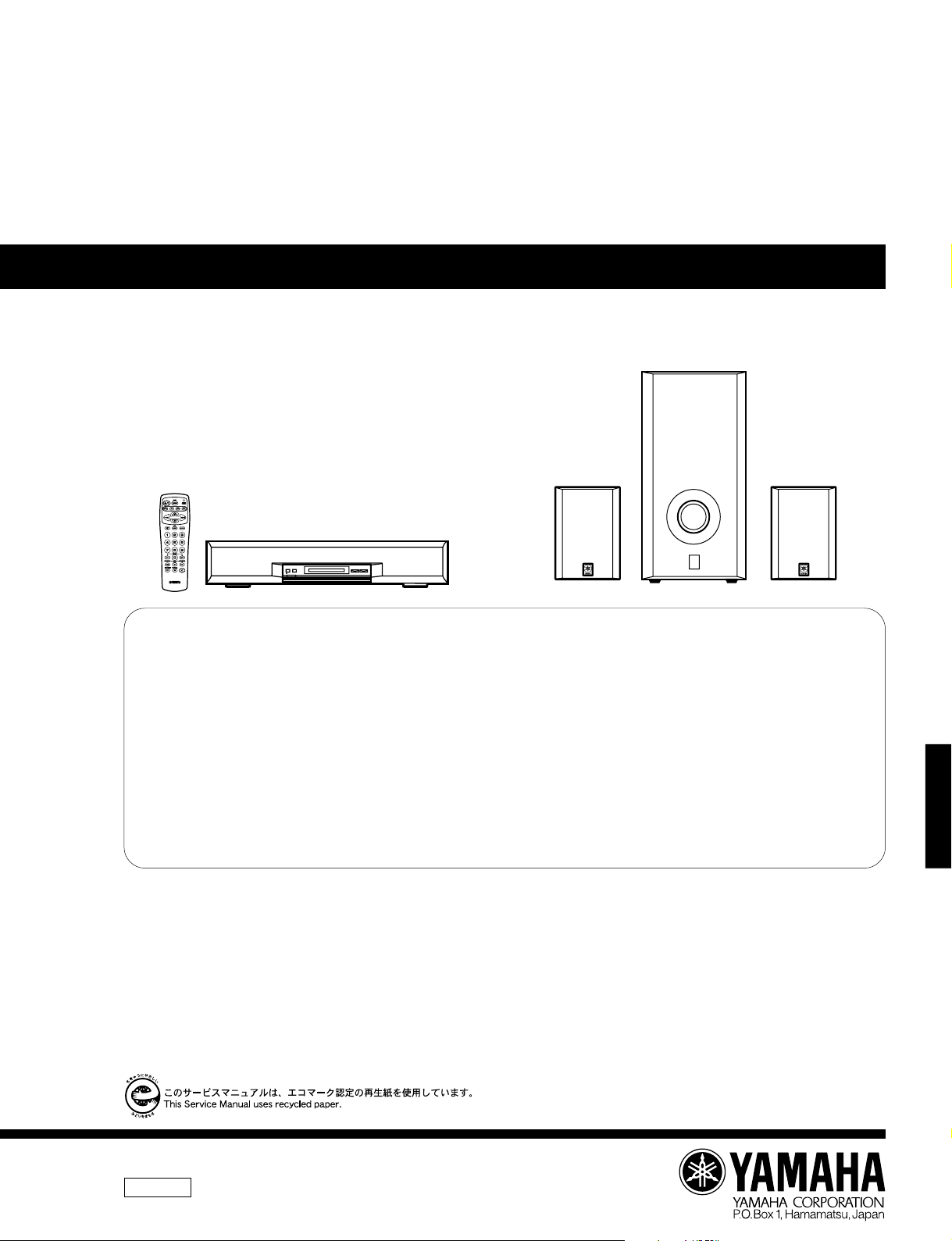
NX-SW70 is composed of SW-AVS70 and NX-AVS70s.
SUBWOOFER
(SW-AVS70)
REAR SPEAKER
(NX-AVS70)
FRONT SPEAKER (AV-S70)
REAR SPEAKER
(NX-AVS70)
IMPORTANT NOTICE
This manual has been provided for the use of authorized YAMAHA Retailers and their service personnel.
It has been assumed that basic service procedures inherent to the industry, and more specifically YAMAHA Products, are already known and understood by the users,
and have therefore not been restated.
WARNING: Failure to follow appropriate service and safety procedures when servicing this product may result in personal injury, destruction of expensive
IMPORTANT: The presentation or sale of this manual to any individual or firm does not constitute authorization, certification or recognition of any applicable
The data provided is believed to be accurate and applicable to the unit(s) indicated on the cover. The research, engineering, and service departments of YAMAHA are
continually striving to improve YAMAHA products. Modifications are, therefore, inevitable and specifications are subject to change without notice or obligation to
retrofit. Should any discrepancy appear to exist, please contact the distributor's Service Division.
WARNING: Static discharges can destroy expensive components. Discharge any static electricity your body may have accumulated by grounding yourself to the
IMPORTANT: Turn the unit OFF during disassembly and part replacement. Recheck all work before you apply power to the unit.
components, and failure of the product to perform as specified. For these reasons, we advise all YAMAHA product owners that any service
required should be performed by an authorized YAMAHA Retailer or the appointed service representative.
technical capabilities, or establish a principle-agent relationship of any form.
ground buss in the unit (heavy gauge black wires connect to this buss).
■ CONTENTS
AV-S70/NX-SW70
TO SERVICE PERSONNEL .........................................1
FRONT/REAR PANELS.......................................... 1—2
SPECIFICATIONS ......................................................... 3
DISASSEMBLY PROCEDURES .................................. 4
TEST PROGRAM MODE........................................ 5—6
DSP DIAG MODE ................................................. 7—13
AV-S70 IC DATA ................................................ 14—20
AV-S70 BLOCK DIAGRAM ................................ 21—22
100697
SW-AVS70 BLOCK DIAGRAM .................................. 23
AV-S70 PRINTED CIRCUIT BOARD ................. 24—33
SW-AVS70 PRINTED CIRCUIT BOARD ........... 34—35
AV-S70 SCHEMATIC DIAGRAM ....................... 36—39
SW-AVS70 SCHEMATIC DIAGRAM..........................40
PARTS LIST ........................................................ 41—54
REMOTE CONTROL TRANSMITTER........................55

AV-S70/NX-SW70
■ TO SERVICE PERSONNEL
Critical Components Information.
Components having special characteristics are marked Z
and must be replaced with parts having specifications equal
to those originally installed.
■ FRONT/REAR PANELS
▼ AV-S70
WALL
OUTLET
EQUIPMENT
UNDER TEST
INSULATING
TABLE
AC LEAKAGE
TESTER OR
EQUIVALENT
AV-S70/NX-SW70
1
41.2
(1–5/8")
241.2 (9–1/2")
170 (6–11/16")
30
(1–3/16")
100 (3–15/16")
110 (4–5/16")
10 (3/8")
600 (23–5/8")
100 (3–15/16")
20 (13/16")
111.5 (4–3/8")
140 (5–1/2")
1.4 (1/16")
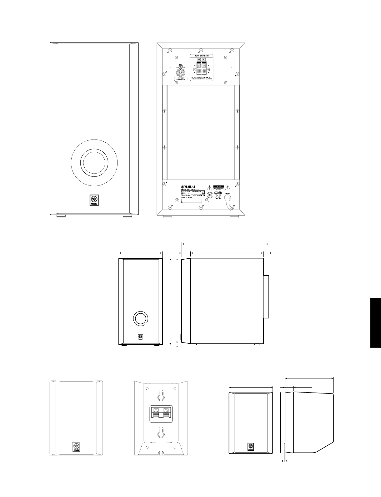
▼ SW-AVS70
AV-S70/NX-SW70
▼ NX-AVS70
200.6 (7–7/8")
40
(1–3/4")
395.6 (15–9/16")
390.1 (15–3/8")
5.5
(3/16")
399 (15–11/16")
335 (13–3/16")
24(15/16")
AV-S70/NX-SW70
2
AV-S70/NX-SW70
■ SPECIFICATIONS
AV-S70
■ AMPLIFIER SECTION
Minimum RMS Output Power per Channel
Front (1kHz, 10% THD, 6Ω)...........................30W + 30W
Signal to Noise Ratio (IHF-A-Network)
TV...............................................................................85dB
Total Harmonic Distortion (1kHz)
TV to Speaker Out, 12.5W/6Ω ................................ 0.08%
Input Sensitivity/Impedance
TV.................................................................. 200mV/50kΩ
■ SPEAKER SECTION
Type ................................................................. Bass reflex type
Speakers ................................................. 8cm (3-1/8”) cone x 2
(Magnetic-Shielding Type)
Maximum Power Handling Capacity ......................... 30W x 2
Impedance ............................................................................ 6Ω
■ GENERAL
Power Supply .................................................... AC230V, 50Hz
Power Consumption..........................................................68W
Dimensions (W X H X D)..........................600 X110 X 243mm
(23-5/8” X 4-5/16” X 9-9/16”)
Weight ........................................................ 7.0kg (15 lbs. 7 oz)
Finish ........................................................................ Gray color
Accessories ...............................................Pin Cord (RCA) X 1
Remote Control Transmitter X 1
Battery (size “AAA”, R03) X 4
Fastener Tape X 2
* Specifications subject to change without notice.
NX-SW70
■ AMPLIFIER SECTION
Minimum RMS Output Power per Channel
Rear (1kHz, 10% THD, 6Ω) ........................... 30W + 30W
Sub Woofer (100Hz, 10% THD, 4Ω).......................... 50W
■ REAR SPEAKER SECTION (NX-AVS70)
Type ........................................................... Closed cabinet type
Speakers ....................................................... 8cm (3-1/8”) cone
(Magnetic-Shielding Type)
Maximum Power Handling Capacity................................30W
Impedance ............................................................................ 6Ω
Dimensions (W X H X D)........................ 100 X 140 X 113mm
(3-15/16” X 5-1/2” X 4-7/16”)
Weight .......................................................... 0.7kg (1 lbs. 8 oz)
Finish ........................................................................ Gray color
■ SUB WOOFER SPEAKER SECTION (SW-AVS70)
Type ......................... Advanced Active Servo Technology type
Speakers ................................................... 16cm (6-5/16”) cone
(Magnetic-Shielding Type)
Maximum Power Handling Capacity................................50W
Impedance ............................................................................ 4Ω
Dimensions (W X H X D)..........................200 X395 X 399mm
(7-7/8” X 15-9/16” X 15-11/16”)
Weight ........................................................ 9.7kg (21 lbs. 6 oz)
Finish ........................................................................ Gray color
■ GENERAL
Power Supply .................................................... AC230V, 50Hz
Power Consumption ..........................................................80W
Accessories ................................. System Cord (DIN plug) X 1
Speaker Cable (15m) X 2
Wall Bracket X 2
Bracket X 2
Wing Bolt X 2
Screw X 2
* Specifications subject to change without notice.
AV-S70/NX-SW70
*
TruBass and the symbol are trademarks of SRS Labs,
inc. in the United States and selected foreign countries.
TruBass technology is incorporated under license from SRS
Labs, inc.
G ................... European model
B ........................ British model
Manufactured under license from Dolby Laboratories.
"Dolby", "Dolby Digital", "Pro Logic", and the double-D
symbol V are trademarks of Dolby Laboratories. © 19921997 Dolby Laboratories. All rights reserved.
3
AV-S70/NX-SW70
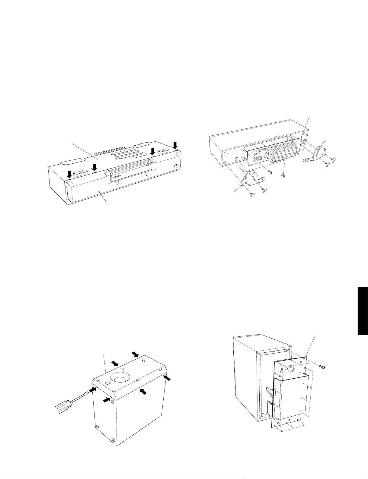
■ AV-S70 DISASSEMBLY PROCEDURES (Remove parts in the order as numbered.)
1. Removal of Grille Assembly.
a. Push up the Grille Assembly with a flat tip screwdriver
or the like inserted from the bottom. (Fig. 1).
b. Keep pushing up the Grille Assembly gradually until it
can be removed.
* The Grille Assembly is fixed securely at 8 dowels. When
removing it, use care not to cause a scratch or any damage to the main unit. When reinstalling it, apply quickdrying type bond to the dowels of the Grille Assembly
and fit it in place securely. (If it is only pushed in, it will
come off easily.)
Bottom
Grill Assembly
Fig. 1
2. Removal of Amplifier Unit
a. Remove 4 wing screws (q) and then remove the Plate
Legs (right and left). (Fig. 2)
b. Remove 4 screws (w). (Fig. 2)
c. Remove 7 screws (e) and then remove the Amplifier
Unit. (Fig. 2)
* Arrow marks are printed to identify the screws to be re-
moved.
Amplifier Unit
Plate Leg
q
q
e
w
Plate Leg
q
q
Fig. 2
■ SW-AVS70 DISASSEMBLY PROCEDURES (Remove parts in the order as numbered.)
a. Removal of Grille Assembly.
a. Push up the Grille Assembly with a flat tip screwdriver
or the like inserted from the bottom. (Fig. 3).
b. Keep pushing up the Grille Assembly gradually until it
can be removed.
* The Grille Assembly is fixed securely at 6 dowels. When
removing it, use care not to cause a scratch or any damage to the main unit. When reinstalling it, apply quick-drying type bond to the dowels of the Grille Assembly and fit
it in place securely. (If it is only pushed in, it will come off
easily.)
Grill Assembly
2. Removal of Amplifier Unit
a. Remove 14 screws (r) and then remove the Amplifier
Unit. (Fig. 4)
* Arrow marks are printed to identify the screws to be re-
moved.
Amplifier Unit
r
AV-S70/NX-SW70
Fig. 3
Fig. 4
4
AV-S70/NX-SW70
■ TEST PROGRAM MODE (AV-S70)
1. Procedure for starting Test Program
With the power turned off, press the POWER key while pressing the VOLUME key and the DSP key simultaneously. This
initiates the Test Program function.
When the Test Program is initiated, “01 DEST-Ex” appears on the FL display.
2. Procedure for selecting and executing Test Program
Using the VOLUME + (UP) key and Volume - (DOWN) key, select the Test Program and then press the INPUT key to execute
it.
3. Procedure for canceling Test Program
There are two methods for cancellation.
a. Turn off the power by pressing the POWER key of the main unit or the remote controller.
b. Select the Test Program “01 DEST-Ex” and press the INPUT key for execution. (The normal mode will be restored.)
4. Details of the Test Program function
01 DEST-B,G1
02 FL+CLEAR
AV-S70/NX-SW70
03 FL CHECK
Display
Function
Destination display/ test program end
Destination display
J:Ja J (Japanese)
J:En J (English)
B,G1 B, G models
FL display segments all light up / BACKUP RAM CLEAR
st
time: FL display segments all light up and standby LED lights up.
1
nd
2
time: RAM CLEAR is executed (RAM CLEAR OK on display)
* State before shipped out of the factory preset.
FL display light-up check
st
1
time: FL display segments all light up and standby LED lights up.
nd
time: Even number segments and digits light up.
2
rd
3
time: Odd number segments and digits light up.
st
time 2nd time 3rd time
1
VIRTUAL TRUBASS
V
DIGITAL ENHANCED
V
SURROUND
V
PRO LOGIC
DSP
V
SURROUND
PRO LOGIC
TRUBASS
ENHANCED
5
AV-S70/NX-SW70
Display
04 DSP Diag
05 Ver-A1.08
06 SUM[47a0]
07 PrCan-OFF
08 Pr!C–P–S–
Function
The DSP DIAG (self-diagnosis) mode is initiated. (Refer to page 7 for the details.)
Microprocessor version / date display
Example of microprocessor display 05 Ver-A1.08
Example of microprocessor date display 05 '99.10.15
What is displayed varies depending on the microprocessor software.
Check sum calculation display / re-calculation
All protection cancellation function ON/OFF
Protection operation history display / clear
C: Center unit amplifier voltage
P: Power circuit voltage
S: Switch side
–: Normal
x: Abnormal
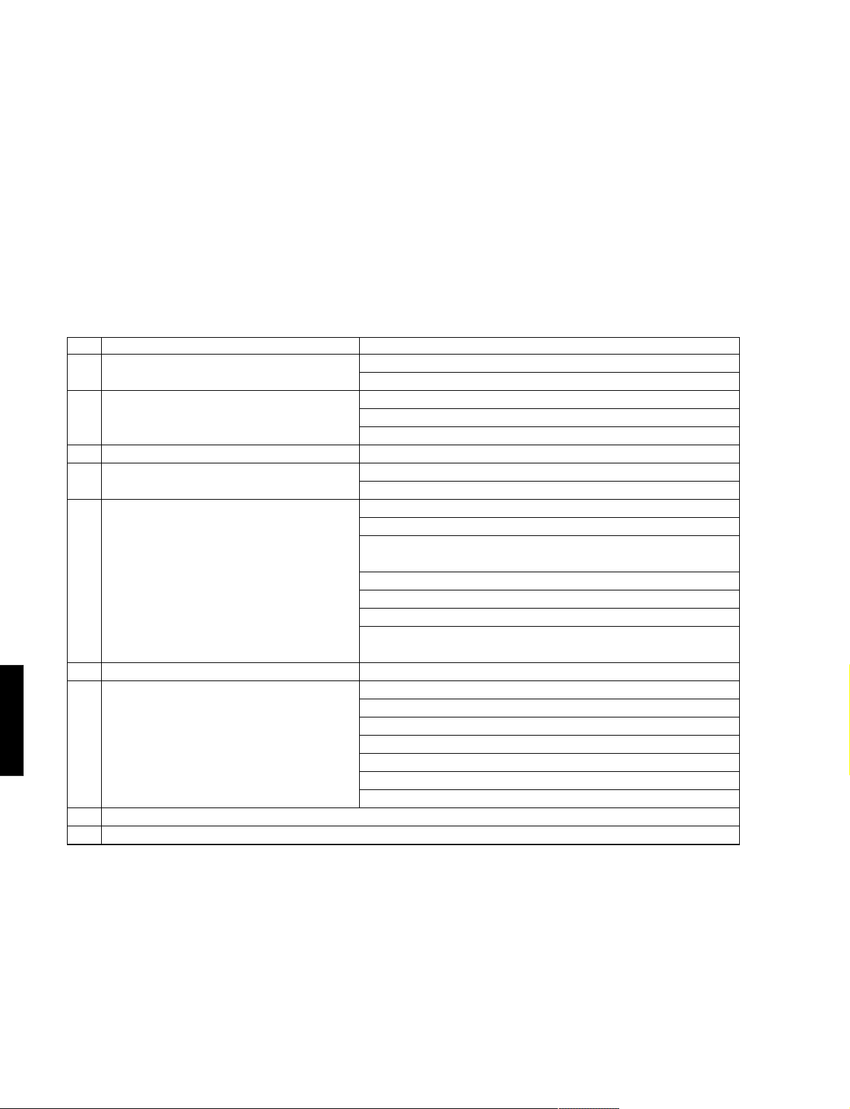
09 Cors- St. ROM collection (EEPROM) check sum calculation/calculation start
When there is a data in the ROM collection area of EEPROM:
10 COR-Clear
Example of display
When there is no data, “NON” appears on the display.
* The ROM collection (EEPROM) is utilized to cope with the data area for backup
and microprocessor bugs partially. The backup memory for the sound field or
the like will be retained semi-permanently even when the plug is disconnected.
No data is written in the parts mounted on the product as single units.
ROM collection (EEPROM) data clear / clear start
Display is provided only when there is data in the ROM collection area of EEPROM
1st time: Data clear confirmation (Clear-ON? displayed)
nd
2
time: Data clear execution (Clear:OK! displayed)
Clear-ON?Clear-ON?
After “
Clear-ON?” is displayed, do not use INPUT key for execution
Clear-ON?Clear-ON?
(because the program contents will be erased).
Using VOLUME + (UP) key and VOLUME - (DOWN) key, select another test
program.
* The IC for ROM collection has a role to help the microprocessor be upgraded. If
the written data is cleared, the old version will be restored.
09 Cors-288b
AV-S70/NX-SW70
6
AV-S70/NX-SW70
■ DSP DIAG MODE (Self-diagnosis)
Use the remote controller supplied as an accessory to select the menu.
1. Procedure for starting DSP DIAG
Referring to TEST PROGRAM MODE in the previous section, select/execute “04 DSP Diag”.
When “04 DSP Diag” is executed, the current input name appears on the display followed by “Video” > “Sel.1to9 Key”.
(The DSP indicator keeps flashing.)
2. Procedure for selecting Main menu and Sub-menu
Using [1] through [9] keys on the remote controller, select the main menu. Soon the sub-menu will appear on the display.
Then, select the sub-menu. Every time the selected key (on the remote controller) is pressed, the sub-menu on the display
changes.
No. Main menu (Display)
1 Analog through Analog Thr.
2 DSP through Dsp Through
3 AC-3 through AC-3 Through
4 Pro logic Pro Logic
5 Speakers set Speakers Set
6 Effect off Effect Off
7 Manual test Manual Test
AV-S70/NX-SW70
8 No function
9 DIAG cancel
Sub-menu (Display)
MAIN BYPASS A.T.M.Bypass
DSP 0dB A.T. DSP 0dB
YSS908-SRAM DspT.908SRAM
YS908 DspT.YSS908
DSP FULL BIT DspT.FullBit
Status (Binary) AC3 Analo2/0
CENTER LARGE ProL.CenterL
EFFECT OFF ProL.Eff.Off
MAIN : SMALL 0dB Sp.MainS 0dB
MAIN : LARGE 0dB Sp.MainL 0dB
LFE/BASS : MAIN
CENTER : NONE Sp.Lfe:M C:N
LFE/BASS : MAIN Sp.LfeBass:M
LFE/BASS : SWFR Sp.Lfe:Swfr
CENTER : NONE Sp.Cent:None
CENTER : SMALL
REAR : SMALL Sp.Ce:S Re:S
EFFECT OFF Effect Off
ALL M.Test All
MAIN L M.Test Left
CENTER M.TestCenter
MAIN R M.Test Right
REAR R M.Test RearR
REAR L M.Test RearL
LFE M.Test Lfe
3. Procedure for canceling DIAG
There are two methods for cancellation of DIAG.
a. Turn off the power by pressing the [POWER] key of the main unit or the remote controller.
b. Press the [9] key of the remote controller. (The normal mode will be restored.)
7
Details of DIAG menu
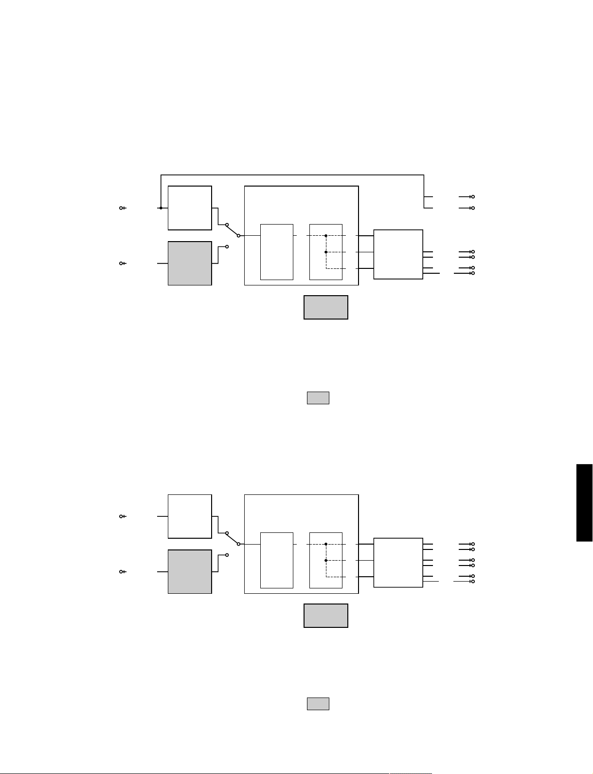
1. Analog Thr.
The input is fixed to use the analog (A/D) and has 2 sub-menu items.
MAIN BYPSS
The main L/R signal is output through the analog bypass without passing the DSP
section.
The main L/R signal passing through the DSP is output through C/LFE and RL/RR.
AV-S70/NX-SW70
CODEC.AD
ANALOG IN
CS4227
DIR2
DIGITAL IN
YM3436
AUX IN : – 20dBV, Both ch
VOLUME : MAX
CN102 (Page 30, C-4)
MAIN L (1kHz) : – 20dBV
MAIN R (1kHz) : – 20dBV
LFE (30Hz) : – 34dBV
REAR L (1kHz) : – 26dBV
REAR R (1kHz) : – 26dBV
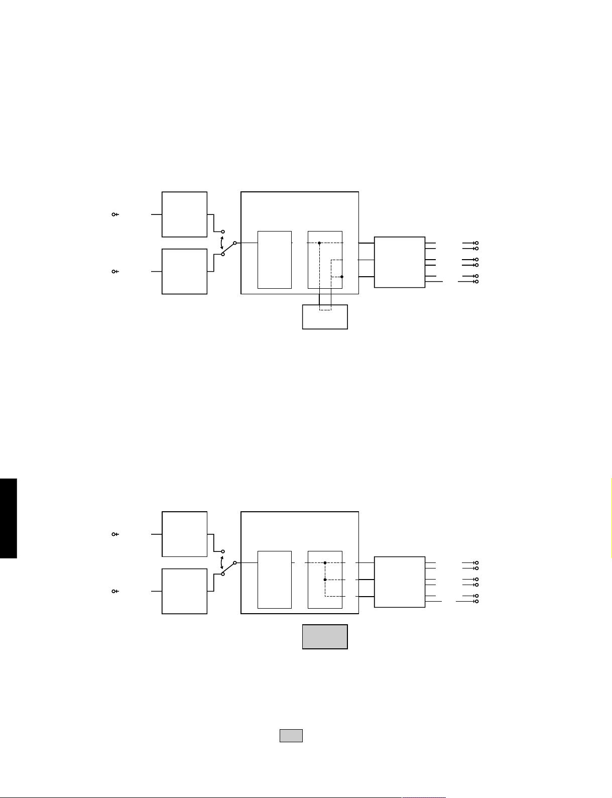
DSP 0dB
The main L/R, C/LFE, RL/RR signals pass through the DSP section.
AC3Dav(YSS908)
DECODER
L/R L/R
256K SRAM
MAIN L
MAIN R
DSP
L/R
L/R
CODEC.DA
CS4227
REAR L
REAR R
CENTER
LFE
The shaded square means that the element included in it does not operate.
AV-S70/NX-SW70
CODEC.AD
ANALOG IN
CS4227
DIR2
DIGITAL IN
YM3436
AUX IN : – 20dBV, Both ch
VOLUME : MAX
CN102 (Page 30, C-4)
MAIN L (1kHz) : – 20dBV
MAIN R (1kHz) : – 20dBV
LFE (30Hz) : – 34dBV
REAR L (1kHz) : – 26dBV
REAR R (1kHz) : – 26dBV
AC3Dav(YSS908)
DECODER
L/R L/R
256K SRAM
DSP
L/R
L/R
CODEC.DA
CS4227
MAIN L
MAIN R
REAR L
REAR R
CENTER
LFE
The shaded square means that the element included in it does not operate.
8
AV-S70/NX-SW70
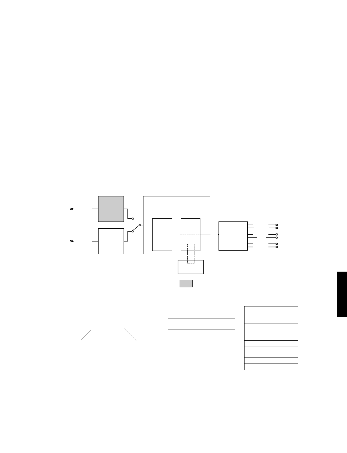
2. DSP Through
In the DIGIT AL input mode, AC3/PCM AUDIO signal is automatically identified. There are 3 sub-menu
items.
YSS908-SRAM
The main L/R signal is sent through AC3D2av into DSP. After passing through SRAM,
the main L/R signal is output through L+R and C/LFE and RL/RR signals through
(L+R)/2.
CODEC.AD
ANALOG IN
CS4227
DIR2
DIGITAL IN
YM3436
AC3Dav(YSS908)
DECODER
(L+R)
DSP
(L+R)
(L+R)
/2
(L+R)
/2
CODEC.DA
CS4227
MAIN L
MAIN R
REAR L
REAR R
CENTER
LFE
AUX IN : – 20dBV, Both ch
VOLUME : MAX
CN102 (Page 30, C-4)
MAIN L (1kHz) : – 20dBV
MAIN R (1kHz) : – 20dBV
LFE (30Hz) : – 34dBV
REAR L (1kHz) : – 26dBV
REAR R (1kHz) : – 26dBV
AV-S70/NX-SW70
256K SRAM
YSS908-SRAM
The main L/R signal is sent through AC3D2av into DSP. The main L/R signal is
output through L+R and C/LFE and RL/RR signals through (L+R)/2.
CODEC.AD
ANALOG IN
CS4227
DIR2
DIGITAL IN
YM3436
AC3Dav(YSS908)
DECODER
L/R
DSP
L/R
L/R
L/R
CODEC.DA
CS4227
MAIN L
MAIN R
REAR L
REAR R
CENTER
LFE
AUX IN : – 20dBV, Both ch
VOLUME : MAX
CN102 (Page 30, C-4)
MAIN L (1kHz) : – 20dBV
MAIN R (1kHz) : – 20dBV
LFE (30Hz) : – 34dBV
REAR L (1kHz) : – 26dBV
REAR R (1kHz) : – 26dBV
9
256K SRAM
The shaded square means that the element included in it does not operate.
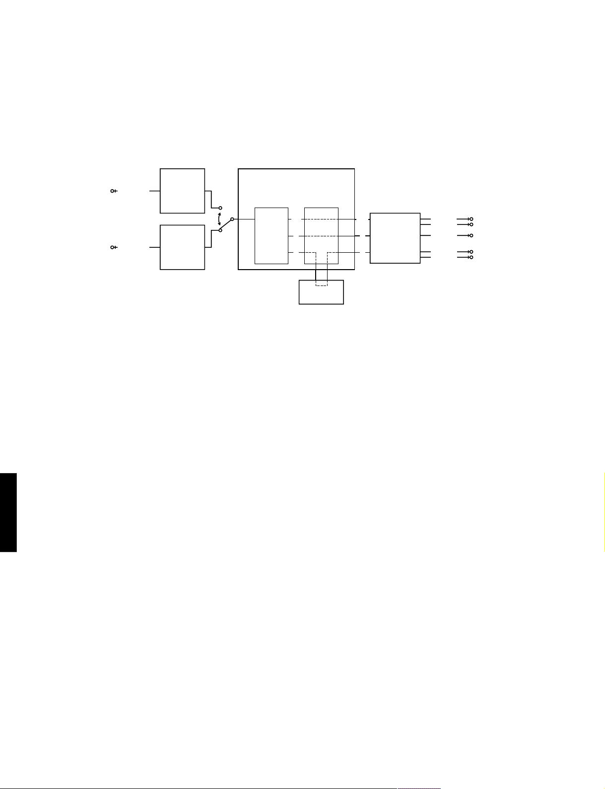
DSP FULL BIT
The main L/R is input through AC3D2av to DSP and then output through all
channels. The head margin is eliminated and the digital data is output in digital full
bit. The same applies as “YSS908” except that the digital data is output in full bit
at D/A.
AUX IN : – 20dBV, Both ch
VOLUME : MAX
CN102 (Page 30, C-4)
MAIN L (1kHz) : – 11dBV
MAIN R (1kHz) : – 11dBV
LFE (30Hz) : – 13dBV
REAR L (1kHz) : – 17dBV
REAR R (1kHz) : – 17dBV
Full bit: The digital data is normally output with a head margin for each of C and RL/RR
channels. In this menu, no head margin is used and the digital data is output in full bit so as to
obtain the A/D and D/A characteristics fully. Note that this means the analog gain after D/A is
larger as compared to L/R. Also, the LFE channel also outputs the signal in full bit.
3. AC-3 Through
Only the signal of the digital system is input. The AC3 signal is decoded and reproduced according to
the input source.
The AC-3 signal in each channel is AC-3 decoded and output through AC3D2av.
The combined status information of the sampling frequency and the number of channels of the AC3 signal appears on the Fl display.
AV-S70/NX-SW70
CODEC.AD
ANALOG IN
AC3Dav(YSS908)
CS4227
DECODER
DIR2
DIGITAL IN
DOLBY DIGITAL
PRO LOGIC
YM3436
Status information
AC3 44.1k 2/0
Sampling frequency Number of channels
DSP
L/R
or
256K SRAM
The shaded square means that the element included in it does not operate.
Sampling frequency (Display)
Analog Analo
32kHz 32k
44.1kHz 44.1k
48kHz 48k
L/R
C/LFEC/LFE
LS/RSLS/RS
CODEC.DA
CS4227
MAIN L
MAIN R
CENTER
LFE
REAR L
REAR R
Number of channels
(Front/Rear) (Display)
1+1 1+1
1/0 1/0
2/0 2/0
3/0 3/0
2/1 2/1
3/1 3/1
2/2 2/2
3/2 5.1ch 3/2
7.1 (DTS) 7.1
AV-S70/NX-SW70
As signal identification is executed in normal AC-3 reproduction, the source (DAT, CD-ROM, etc) without digital
data bit of IEC958 cannot be reproduced even when it is AC-3 encoded. On the other hand, as this menu does not
execute such digital data bit identification, these sources can be AC-3 reproduced. (To measure characteristics
during AC-3 reproduction, use the AC-3 decoded sine wave.)
However, note that with the sources that have not been AC-3 encoded, a decode error occurs and muting is
applied. In addition, by displaying the combined status information of the sampling frequency and the number of
channels of the AC-3 signal on the FL display, malfunction of the decoder can be detected.
10
AV-S70/NX-SW70
4. Pro Logic
The sub-menu items include selection of Pro-logic (The auto input balance is off.) and EFFECT OFF.
CENTER LARGE
When the analog, PCM audio or AC-3 2/0 mode is used, L, R, C, S signals are prologic decoded and output. When the AC-3 mode other than 2/0 is used, the pro logic
function does not work and the signals are AC-3 reproduced.
CODEC.AD
ANALOG IN
CS4227
DIR2
DIGITAL IN
YM3436
AUX IN : – 20dBV, Both ch
VOLUME : MAX
CN102 (Page 30, C-4)
MAIN L (1kHz) : – 20dBV
MAIN R (1kHz) : – 20dBV
LFE (30Hz) : – 28dBV
REAR L (1kHz) : < – 45dBV
REAR R (1kHz) : < – 45dBV
AC3Dav(YSS908)
DECODER
DOLBY DIGITAL
PRO LOGIC
L/R
or
C
S
256K SRAM
AUX IN : – 20dBV, L ch only
VOLUME : MAX
CN102 (Page 30, C-4)
DSP
MAIN L (1kHz) : – 20dBV
MAIN R (1kHz) : < – 45dBV
LFE (30Hz) : – 32dBV
REAR L (1kHz) : < – 45dBV
REAR R (1kHz) : < – 45dBV
L/R
CODEC.DA
C
S
CS4227
MAIN L
MAIN R
CENTER
REAR L
REAR R
AV-S70/NX-SW70
11
EFFECT OFF
The L/R signal is output through MAIN BYPASS.

5. Speakers Set (for reference only)
This menu is for checking during the production process and not for servicing.
The input L/R signal is output through the specified channels according to the sub-menu.
There are 7 sub-menu items.
The signal output from the DSP section is normally in the EFFECT OFF state in the menus from 1 to
3. In the menus after that, the same signal as in the menu of 2. DSP THROUGH: YSS908 is output.
The analog switch settings in each sub-menu are as shown in the following table.
Output
Sub-menu
1 MAIN : SMALL 0dB
2 MAIN : LARGE 0dB
3 LFE/BASS : MAIN CENTER : NONE
4 LFE/BASS : MAIN
5 LFE/BASS : SUBWOOFER
6 CENTER : NONE
7 CENTER : SMALL REAR : SMALL
CENTER
LARGE
LARGE
NONE
LARGE
LARGE
NONE
SMALL
REAR
LARGE
LARGE
LARGE
LARGE
LARGE
LARGE
SMALL
MAIN
SMALL
LARGE
LARGE
LARGE
LARGE
LARGE
LARGE
MAIN LEVEL
LFE/BASS
0dB
0dB
0dB
0dB
0dB
0dB
0dB
SWFR
SWFR
MAIN
MAIN
SWFR
SWFR
SWFR
MAIN L
L
L
L
LFE+FL
X
C+FL
FL
MAIN R
R
R
R
LFE+FR
X
C+FR
FR
CENTER
X
X
X
X
X
X
C
AV-S70/NX-SW70
X
X
X
X
X
X
RR
SUBWOOFER
L+R
LFE
C+RL+RR+LFE
REAR L
X
X
X
X
X
X
RL
REAR R
X
X
X
X
* In Sub-menu 1, the lower range content of the MAIN L/R is output at SWFR as well.
* In Sub-menu 7, the lower range content of LFE, CENTER and REAR is output at SWFR as well.
LARGE: Signals are output in all bandwidths.
SMALL: Only signals lower than 90Hz are mixed in the channel specified by LFE/BASS.
NONE: The center contents are distributed to the MAIN L/R channels after -3dB.
SWFR: SUBWOOFER
Output: The signal before MASTER VOLUME is indicated.
Sub-menu Main application
MAIN : SMALL 0dB
Confirmation of high/low pass filter characteristics and gain when BASS REDIRECTION is used.
MAIN : LARGE 0dB Reference for Sub-menu 1 and 2
LFE/BASS : MAIN CENTER : NONE Confirmation of effect of the mix circuit to the main channel.
LFE/BASS : MAIN Confirmation of gain of BASS MIX.
LFE/BASS : SWFR Confirmation of the maximum output of LFE.
CENTER : NONE Confirmation of gain of CENTER MIX.
CENTER : SMALL REAR : SMALL
Confirmation of high/low pass filter characteristics and gain when BASS REDIRECTION is used.
AV-S70/NX-SW70
12

AV-S70/NX-SW70
6. Effect Off
All effect functions are turned off.
7. Manual Test
The test noise is output by the noise generator with a built-in DSP through the channels specified by
the sub-menu.
ALL Noise is output through all channels.
MAIN L Noise is output through the MAIN L channel.
CENTER Noise is output through the CENTER channel.
MAIN R Noise is output through the MAIN R channel.
REAR R Noise is output through the REAR R channel.
REAR L Noise is output through the REAR L channel.
LFE Noise is output through the LFE (sub-woofer) channel.
8. No function
9. DIAG cancel
The DSP DIAG is canceled.
AV-S70/NX-SW70
13
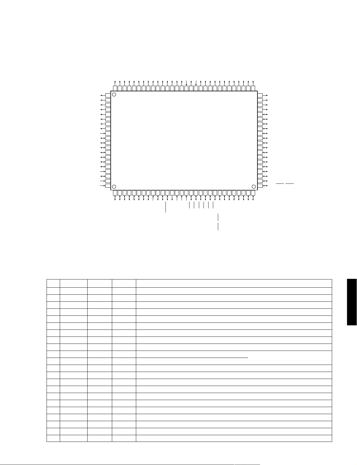
■ AV-S70 IC DATA
AV-S70/NX-SW70
IC701 : M30218FCFP (16 bit
P67/FLD7
P66/FLD6
P65/FLD5
P64/FLD4
P63/FLD3
P62/FLD2
P61/FLD1
P60/FLD0
P107/AN7
P106/AN6
P105/AN5
P104/AN4
P103/AN3
P102/AN2
P101/AN1
P100/AN0
VEE
AVSS
VREF
AVCC
81
82
83
84
85
86
87
88
89
90
91
92
93
94
95
96
97
98
99
100
µ-COM)
P50/FLD8
P51/FLD9
P52/FLD10
P53/FLD11
P54/FLD12
P55/FLD13
P56/FLD14
P57/FLD15
P00/FLD16
P01/FLD17
P02/FLD18
P03/FLD19
P04/FLD20
P05/FLD21
P06/FLD22
VSS
P17/FLD23
VCC
P10/FLD24
P11/FLD25
P12/FLD26
P13/FLD27
P14/FLD28
P15/FLD29
P16/FLD30
P17/FLD31
P20/FLD32
P21/FLD33
8079787776757473727170696867666564636261605958575655545352
123456789
P93/SIN2
P92/SSTB2
P94/SOUT2
P95/SCLK21
P96/DA1/SCLK22
P97/DA0/CLKOUT/DIMOUT
101112131415161718192021222324252627282930
XIN
VSS
VCC
XOUT
RESET
CNVSS
P87/XCIN
P90/SRDY2
P91/SBUSY2
P86/XCOUT
P85/INT5
P84/INT4
P83/INT3
P82/INT2
P81/INT1
P80/INT0
P73/TA0IN/TA3OUT
P76/TA3IN/TA1OUT/CLK1
P74/TA1IN/TA4OUT/TXD1
P75/TA2IN/TA0OUT/RXD1
P72/TB2IN
P22/FLD34
P23/FLD35
51
50
49
48
47
46
45
44
43
42
41
40
39
38
37
36
35
34
33
32
31
P71/TB1IN
P70/TB0IN
P24/FLD36
P25/FLD37
P26/FLD38
P27/FLD39
P30/FLD40
P31/FLD41
P32/FLD42
P33/FLD43
P34/FLD44
P35/FLD45
P36/FLD46
P37/FLD47
P40/FLD48
P41/FLD49
P42/FLD50
P43/FLD51
P44/TXD0/FLD52
P45/RXD0/FLD53
P46/CLK0/FLD54
P47/CTS0/RTS0/FLD55
P77/TA4IN/TA2OUT/CTS1/RTS1/CLKS1
No. PORT Name IN/OUT Function
1 P97 CMOS OUT BASS BOOST OUT [0:ON]
2 P96 CMOS OUT Center unit, RL,RR,SW MUTE OUT [0:MUTE ON]
3 P95 CMOS OUT (DSP) SERIAL/CODEC CLK OUT (SCK)
4 P94 CMOS OUT (DSP) SERIAL/CODEC DATA OUT (SDT)
5 P93 CMOS OUT (DSP) DIR2 CCK (CCK)
6 P92 CMOS OUT (DSP) DIR2 CLD (CLD)
7 P91 CMOS OUT (DSP) AC3D CE1 OUT (CEAC1)
8 P90 CMOS OUT (DSP) AC3D CE2 OUT (CEAC2)
9 CNVSS - - Connected to VSS (GND) via a resistance (5.1kΩ)
10 P87 CMOS OUT Switching of analog input selector (4052) to A OUT A B [00:GND 01:TV ]
11 P86 CMOS OUT Switching of analog input selector (4052) to B OUT [10:AUX 11:VCR]
12 RESET - - RESET [0:RESET]
13 XOUT - - 10 MHz IN (Feedback resistance included)
14 VSS - - GND
15 XIN - - 10 MHz IN (Feedback resistance included)
16 VCC - - +5V power supply
17 P85 INT5 INT-IN (DSP) DIR2 ERR IN (ERRD)
18 P84 INT4 INT-IN (DSP) AC3D MUTE IN (ERRA)
19 P83 (INT3) IN (DSP) DIR2 CD0 IN (CD0)
20 P82 (INT2) IN Center unit amplifier voltage detect IN (Protection) [0: abnormality exists]
21 P81 INT1 INT-IN Remote controller IN
22 P80 INT0 INT-IN Power down DC detect IN [0:POWER DOWN]
AV-S70/NX-SW70
14
AV-S70/NX-SW70
IC701 : M30218FCFP (16 bit
No. PORT Name IN/OUT Function
23 P77 CMOS OUT (DSP) /IC AC3D OUT (/ICAC)
24 P76 CLK1 S-CLK (DSP) AC3D CLK OUT(CLKAC) (Serial I/O-1)
25 P75 RxD1 S-IN (DSP) AC3D DATA IN(RXAC) (Serial I/O-1)
26 P74 TxD1 S-OUT (DSP) AC3D DATA OUT(TXAC) (Serial I/O-1)
27 P73 CMOS OUT (DSP) CODEC CE OUT (CECOD)
28 P72 CMOS OUT Analog switch (LC78212) CE OUT [0: Address 1: Data]
29 P71 CMOS OUT Electronic VR (TC9482) STB OUT [1:ON]
30 P70 CMOS OUT CE OUT to E2PROM [1: DATA transfer]
31 P47 CTS0 OUT TruBass Switching OUT/Busy OUT to flash writer [1:ON]
32 P46 CLK0 S-CLK LC78212/TC9482/CLK OUT to E2PROM/CLK IN from flash writer (Serial I/O-0)
33 P45 RxD0 S-IN DATA IN from E2PROM/DATA IN from flash writer (Serial I/O-0)
34 P44 TxD0 S-OUT LC78212/TC9482/DATA OUT to E2PROM/DATA OUT from flash writer (Serial I/O-0)
35 P43 P-OD OUT SW primary power supply relay control OUT [0:ON]
36 P42 P-OD OUT 6ch speaker relay control OUT [1:ON]
37 P41 - IN SW PRE OUT in use/unused IN [1: in use]
38 P40 P-OD OUT STANDBY LED OUT [1: light up]
39 P37 FLD47 OUT DIGIT 13 (13G) [VEE external pull-down required]
40 P36 FLD46 OUT DIGIT 12 (12G) [VEE external pull-down required]
41 P35 FLD45 OUT DIGIT 11 (11G) [VEE external pull-down required]
42 P34 FLD44 OUT DIGIT 10 (10G) [VEE external pull-down required]
43 P33 FLD43 OUT DIGIT 9 ( 9G) [VEE external pull-down required]
44 P32 FLD42 OUT DIGIT 8 ( 8G) [VEE external pull-down required]
45 P31 FLD41 OUT DIGIT 7 ( 7G) [VEE external pull-down required]
46 P30 FLD40 OUT DIGIT 6 ( 6G) [VEE external pull-down required]
47 P27 FLD39 OUT DIGIT 5 ( 5G) [VEE external pull-down required]
48 P26 FLD38 OUT DIGIT 4 ( 4G) [VEE external pull-down required]
49 P25 FLD37 OUT DIGIT 3 ( 3G) [VEE external pull-down required]
50 P24 FLD36 OUT DIGIT 2 ( 2G) [VEE external pull-down required]
51 P23 FLD35 OUT DIGIT 1 ( 1G) [VEE external pull-down required]
52 P22 FLD34 OUT SEGMENT 1 (P1) [VEE external pull-down required]
53 P21 FLD33 OUT SEGMENT 2 (P2) [VEE external pull-down required]
54 P20 FLD32 OUT SEGMENT 3 (P3) [VEE external pull-down required]
55 P17 FLD31 OUT SEGMENT 4 (P4) (VEE internal pull-down)
56 P16 FLD30 OUT SEGMENT 5 (P5) (VEE internal pull-down)
57 P15 FLD29 OUT SEGMENT 6 (P6) (VEE internal pull-down)
58 P14 FLD28 OUT SEGMENT 7 (P7) (VEE internal pull-down)
59 P13 FLD27 OUT SEGMENT 8 (P8) (VEE internal pull-down)
AV-S70/NX-SW70
60 P12 FLD26 OUT SEGMENT 9 (P9) (VEE internal pull-down)
61 P11 FLD25 OUT SEGMENT 10 (P10) (VEE internal pull-down)
62 P10 FLD24 OUT SEGMENT 11 (P11) (VEE internal pull-down)
63 VCC - - +5V power supply
64 P07 FLD23 OUT SEGMENT 12 (P12) (VEE internal pull-down)
65 VSS - - GND
66 P06 FLD22 OUT SEGMENT 13 (P13) (VEE internal pull-down)
67 P05 FLD21 OUT SEGMENT 14 (P14) (VEE internal pull-down)
68 P04 FLD20 OUT SEGMENT 15 (P15) (VEE internal pull-down)
69 P03 FLD19 OUT SEGMENT 16 (P16) (VEE internal pull-down)
70 P02 FLD18 OUT SEGMENT 17 (P17) (VEE internal pull-down)
71 P01 FLD17 OUT SEGMENT 18 (P18) (VEE internal pull-down)
72 P00 FLD16 OUT SEGMENT 19 (P19) (VEE internal pull-down)
73 P57 FLD15 OUT SEGMENT 20 (P20) (VEE internal pull-down)
74 P56 FLD14 OUT SEGMENT 21 (P21) (VEE internal pull-down)
75 P55 FLD13 OUT SEGMENT 22 (P22) (VEE internal pull-down)
76 P54 FLD12 OUT SEGMENT 23 (P23) (VEE internal pull-down)
77 P53 FLD11 OUT SEGMENT 24 (P24) (VEE internal pull-down)
µ-COM)
15
 Loading...