

Yamaha NS-BP80 Service Manual
CRX-040/CRX-140/
NS-BP80
101157
SERVICE MANUAL
IMPORTANT NOTICE
This manual has been provided for the use of authorized YAMAHA Retailers and their service personnel.
It has been assumed that basic service procedures inherent to the industry, and more specifi cally YAMAHA Products, are already known
and understood by the users, and have therefore not been restated.
WARNING:
Failure to follow appropriate service and safety procedures when servicing this product may result in personal injury,
destruction of expensive components, and failure of the product to perform as specifi ed. For these reasons, we advise
all YAMAHA product owners that any service required should be performed by an authorized YAMAHA Retailer or
the appointed service representative.
IMPORTANT:
The presentation or sale of this manual to any individual or fi rm does not constitute authorization, certifi cation or
recognition of any applicable technical capabilities, or establish a principle-agent relationship of any form.
The data provided is believed to be accurate and applicable to the unit(s) indicated on the cover. The research, engineering, and service
departments of YAMAHA are continually striving to improve YAMAHA products. Modifications are, therefore, inevitable and
specifi cations are subject to change without notice or obligation to retrofi t. Should any discrepancy appear to exist, please contact the
distributor's Service Division.
WARNING:
Static discharges can destroy expensive components. Discharge any static electricity your body may have
accumulated by grounding yourself to the ground buss in the unit (heavy gauge black wires connect to this buss).
IMPORTANT:
Turn the unit OFF during disassembly and part replacement. Recheck all work before you apply power to the unit.
■ CONTENTS
TO SERVICE PERSONNEL ............................................2
PREVENTION OF ELECTROSTATIC DISCHARGE ......5
SYSTEM COMPOSITION /
システム構成
....................... 6
FRONT PANELS ......................................................... 7–9
REAR PANELS ....................................................... 10–13
REMOTE CONTROL PANELS ..................................... 14
SPECIFICATIONS /
参考仕様
................................. 15–17
INTERNAL VIEW .......................................................... 18
DISASSEMBLY PROCEDURES /
分解手順
...........19–22
UPDATING FIRMWARE /
ファームウェアのアップデート
............................ 23–33
SELF-DIAGNOSTIC FUNCTION /
ダイアグ(自己診断機能)
..................................... 34–48
DISPLAY DATA .............................................................49
IC DATA ...................................................................50–54
BLOCK DIAGRAM ........................................................ 55
PRINTED CIRCUIT BOARDS .................................56–65
PIN CONNECTION DIAGRAMS ...................................66
SCHEMATIC DIAGRAMS ....................................... 67–74
REPLACEMENT PARTS LIST ................................ 75–90
REMOTE CONTROL ...............................................91–92
USING USEFUL FUNCTIONS /
便利な機能
...........93–98
'09.12
P.O.Box 1, Hamamatsu, Japan
The MCR-040 consists of the CRX-040 and NS-BP80.
The MCR-140 consists of the CRX-140 and NS-BP80.
MCR-040 は、CRX-040 および NS-BP80 で構成されています。
MCR-140 は、CRX-140 および NS-BP80 で構成されています。
Copyright © 2009 All rights reserved.
This manual is copyrighted by YAMAHA and may not be copied or
redistributed either in print or electronically without permission.
CD RECEIVER/
SPEAKER
CRX-040/CRX-140/
NS-BP80
MICRO COMPONENT SYSTEM
MCR-040/MCR-140
2
CRX-040/CRX-140/NS-BP80
CRX-040/CRX-140/
NS-BP80
This product contains chemicals known to the State of California to cause cancer, or birth defects or other reproductive
harm.
DO NOT PLACE SOLDER, ELECTRICAL/ELECTRONIC OR PLASTIC COMPONENTS IN YOUR MOUTH FOR ANY REASON
WHATSOEVER!
Avoid prolonged, unprotected contact between solder and your skin! When soldering, do not inhale solder fumes or
expose eyes to solder/flux vapor!
If you come in contact with solder or components located inside the enclosure of this product, wash your hands before
handling food.
1. Critical Components Information
Components having special characteristics are marked ⚠
and must be replaced with parts having specifications equal
to those originally installed.
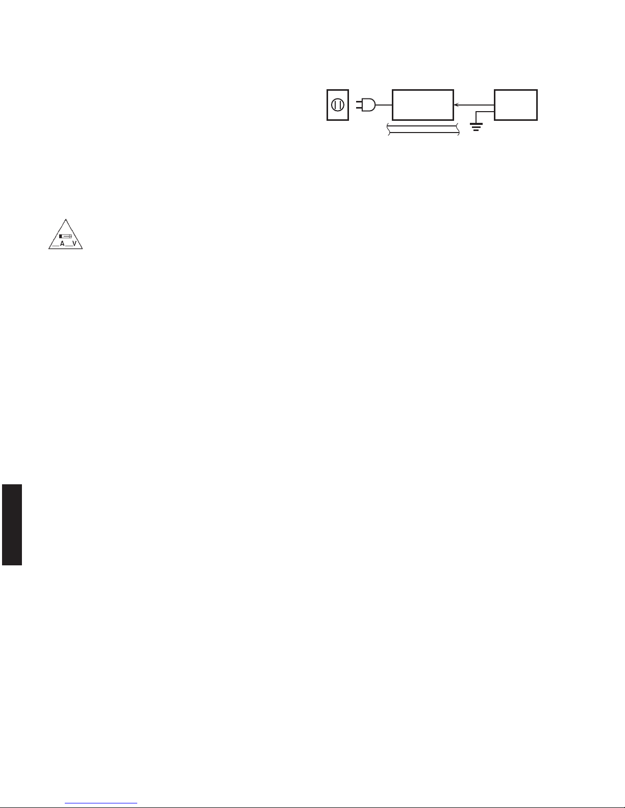
2. Leakage Current Measurement (For 120V Models Only)
When service has been completed, it is imperative to verify
that all exposed conductive surfaces are properly insulated
from supply circuits.
• Meter impedance should be equivalent to 1500 ohms
shunted by 0.15 μF.
本機に搭載されているすべての基板およびハンダ付けに
よる接合部は無鉛ハンダでハンダ付けされています。
無鉛ハンダにはいくつかの種類がありますが、修理時に
は下記のような無鉛ハンダの使用を推奨します。
Sn+Ag+Cu(錫+銀+銅)
Sn+Cu(錫 + 銅)
Sn+Zn+Bi(錫 + 亜鉛 + ビスマス)
注意:
無鉛ハンダの融点温度は通常の鉛入りハンダに比べ 30 〜
40℃程度高くなっていますので、それぞれのハンダに合っ
たハンダごてをご使用ください。
All of the P.C.B.s installed in this unit and solder joints are
soldered using the lead free solder.
Among some types of lead free solder currently available,
it is recommended to use one of the following types for
the repair work.
• Sn + Ag + Cu (tin + silver + copper)
• Sn + Cu (tin + copper)
• Sn + Zn + Bi (tin + zinc + bismuth)
Caution:
As the melting point temperature of the lead free solder
is about 30°C to 40°C (50°F to 70°F) higher than that of
the lead solder, be sure to use a soldering iron suitable
to each solder.
■ TO SERVICE PERSONNEL
• Leakage current must not exceed 0.5mA.
• Be sure to test for leakage with the AC plug in both
polarities.
WALL
OUTLET
EQUIPMENT
UNDER TEST
AC LEAKAGE
TESTER OR
EQUIVALENT
INSULATING
TABLE
WARNING: CHEMICAL CONTENT NOTICE!
About lead free solder /
無鉛ハンダについて
For U model
“CAUTION”
“F1: FOR CONTINUED PROTECTION AGAINST RISK OF FIRE, REPLACE ONLY WITH SAME TYPE 1.25A,
125V FUSE.”
For C model
CAUTION
F1: REPLACE WITH SAME TYPE 1.25A, 125V FUSE.
ATTENTION
F1: UTILISER UN FUSIBLE DE RECHANGE DE MÉME TYPE DE 1.25A, 125V.

3
CRX-040/CRX-140/NS-BP80
CRX-040/CRX-140/
NS-BP80
CAUTION
Danger of explosion if battery is incorrectly replaced.
Replace only with the same or equivalent type.
WARNING: Lithium batteries
注意
正しい電池と交換しないと爆発が起きるおそれがありま
す。
同一型名または同等品以外の電池とは絶対に交換しない
ようにしてください。
WARNING:
Lithium batteries are dangerous because
they can be exploded by improper handling. Observe the
following precautions when handling or replacing lithium
batteries.
• Leave lithium battery replacement to qualified service
personnel.
• Always replace with batteries of the same type.
• When installing on the PC board by soldering, solder
using the connection terminals provided on the battery
cells. Never solder directly to the cells. Perform the
soldering as quickly as possible.
• Never reverse the battery polarities when installing.
• Do not short the batteries.
• Do not attempt to recharge these batteries.
• Do not disassemble the batteries.
• Never heat batteries or throw them into fire.
ADVARSEL!
Lithiumbatteri –Eksplosionsfare ved fejlagtig håndtering.
Udskiftning må kun ske med batteri af samme fabrikat og
type. Levér det brugte batteri tilbage til leverandøren.
VARNING
Explosionsfara vid felaktigt batteribyte. Använd samma
batterityp eller an ekvivalent typ som rekommenderas
av apparattillverkaren. Kassera använt batteri enligt
fabrikantens instruktion.
VAROITUS
Paristo voi räjähtää, jos se on virheellisesti asennettu.
Vaihda paristo ainoastaan laitevalmistajan suosittelemaan
tyyppiin. Hävitä käytetty peristo valmistajan ohjeiden
mukaisesti.
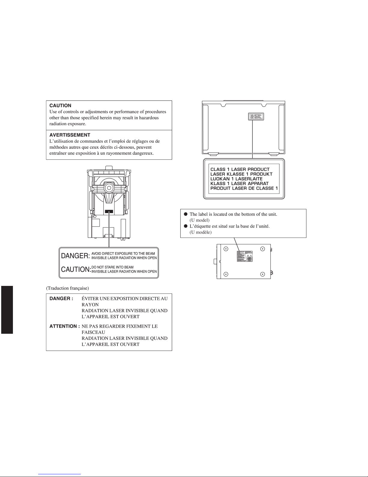
WARNING: Laser Safety
This product contains a laser beam component. This component may emit invisible, as well as visible radiation,
which may cause eye damage. To protect your eyes and skin from laser radiation, the following precautions must
be used during servicing of the unit.
1) When testing and/or repairing any component within the product, keep your eyes and skin more than 30 cm/1 feet
away from the laser pick-up unit at all times. Do not stare at the laser beam at any time.
2) Do not attempt to readjust, disassemble or repair the laser pick-up, unless noted elsewhere in this manual.
3) CAUTION: Use of controls, adjustments or performance of procedures other than those specified herein may result in
hazardous radiation exposure.
Laser Emitting conditions:
1) When the Top Cover is removed, and the STANDBY/ON SW is turned to the “ON” position, the laser component will
emit a beam for several seconds to detect if a disc is present. During this time (5-10 sec.) the laser may radiate
through the lens of the laser pick-up unit. Do not attempt any servicing during this period!
If no disc is detected, the laser will stop emitting the beam. When a disc is loaded, you will not be exposed to any
laser emissions.
2) The laser power level can be adjusted with the VR on the pick-up PWB, however, this level has been set by the factory
prior to shipping from the factory. Do not adjust this laser level control unless instruction is provided elsewhere in this
manual. Adjustment of this control can increase the laser emission level from the device.
4
CRX-040/CRX-140/NS-BP80
CRX-040/CRX-140/
NS-BP80
Laser Diode Properties
Type: Semiconductor laser GaAs/GaAlAs
Wavelength: 780 nm
Output power: 10 mW
The primary side of the power supply carries live mains voltage when the player is connected to the mains even
when the player is switched off !
This primary area is not shielded so it is possible to accidentally touch copper tracks and/or components when servicing
the player.
Service personnel have to take precautions to prevent touching this area or components in this area.
Note:
The screws on the loader mechanism may never be touched, removed or re-adjusted.
Handle the loader mechanism with care when the unit has to be exchanged!
The loader mechanism is very sensitive for dropping or giving shocks.
Warning for power supply
5
CRX-040/CRX-140/NS-BP80
CRX-040/CRX-140/
NS-BP80
Some semiconductor (solid state) devices can be damaged easily by static electricity. Such components commonly are
called Electrostatically Sensitive (ES) Devices. Examples of typical ES devices are integrated circuits and some field-effect
transistors and semiconductor “chip” components. The following techniques should be used to help reduce the incidence
of component damage caused by electrostatic discharge (ESD).
1. Immediately before handling any semiconductor component or semiconductor-equipped assembly, drain off any ESD
on your body by touching a known earth ground. Alternatively, obtain and wear a commercially available discharging
ESD wrist strap, which should be removed for potential shock reasons prior to applying power to the unit under test.
2. After removing an electrical assembly equipped with ES devices, place the assembly on a conductive surface such as
aluminum foil, to prevent electrostatic charge buildup or exposure of the assembly.
3. Use only a grounded-tip soldering iron to solder or unsolder ES devices.
4. Use only an anti-static solder removal device. Some solder removal devices not classified as “anti-static (ESD
protected)” can generate electrical charge sufficient to damage ES devices.
5. Do not use freon-propelled chemicals. These can generate electrical charges sufficient to damage ES devices.
6. Do not remove a replacement ES device from its protective package until immediately before you are ready to install it.
(Most replacement ES devices are packaged with leads electrically shorted together by conductive foam, aluminum foil
or comparable conductive material).
7. Immediately before removing the protective material from the leads of a replacement ES device, touch the protective
material to the chassis or circuit assembly into which the device will be installed.
CAUTION: Be sure no power is applied to the chassis or circuit, and observe all other safety precautions.
8. Minimize bodily motions when handling unpackaged replacement ES devices. (Otherwise harmless motion such as
brushing together of your fabric clothes or lifting of your foot from a carpeted floor can generate static electricity (ESD)
sufficient to damage an ES device).
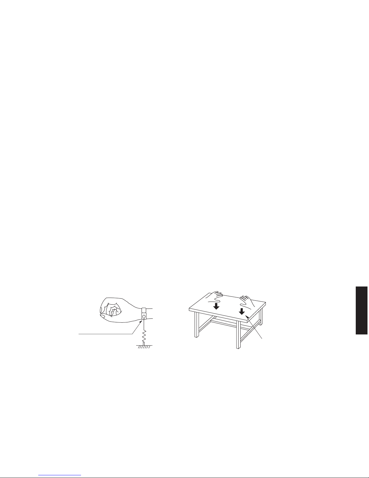
Grounding for electrostatic breakdown prevention
1. Human body grounding.
Use the antistatic wrist strap to discharge the static electricity from your body.
2. Work table grounding.
Put a conductive material (sheet) or steel sheet on the area where the optical pickup is placed and ground the sheet.
Caution:
The static electricity of your clothes will not be grounded through the wrist strap. So take care not to let your clothes touch
the optical pickup.
■ PREVENTION OF ELECTROSTATIC DISCHARGE
1M-ohms
Conductive material
(sheet) or steel sheet
Anti-static wrist strap
6
CRX-040/CRX-140/NS-BP80
CRX-040/CRX-140/
NS-BP80
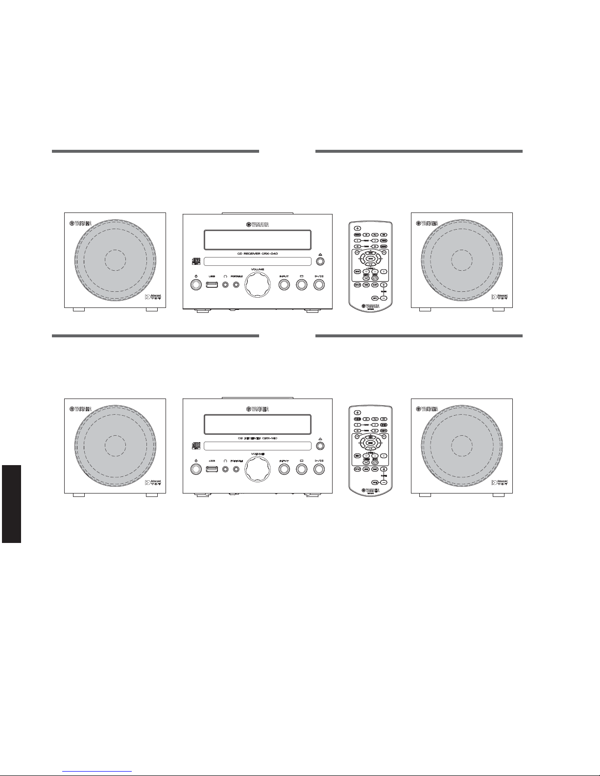
■ SYSTEM COMPOSITION /
システム構成
The MCR-040 consists of the CRX-040 and NS-BP80.
The MCR-140 consists of the CRX-140 and NS-BP80.
MCR-040 は、CRX-040 および NS-BP80 で構成されています。
MCR-140 は、CRX-140 および NS-BP80 で構成されています。
▼ NS-BP80 ▼ NS-BP80
▼ NS-BP80 ▼ NS-BP80
MCR-040
MCR-140
▼ CRX-140
▼ CRX-040
7
CRX-040/CRX-140/NS-BP80
CRX-040/CRX-140/
NS-BP80
U, T, K, A, B, G, L, V, J models U, T, A, B, G, L, V, J models
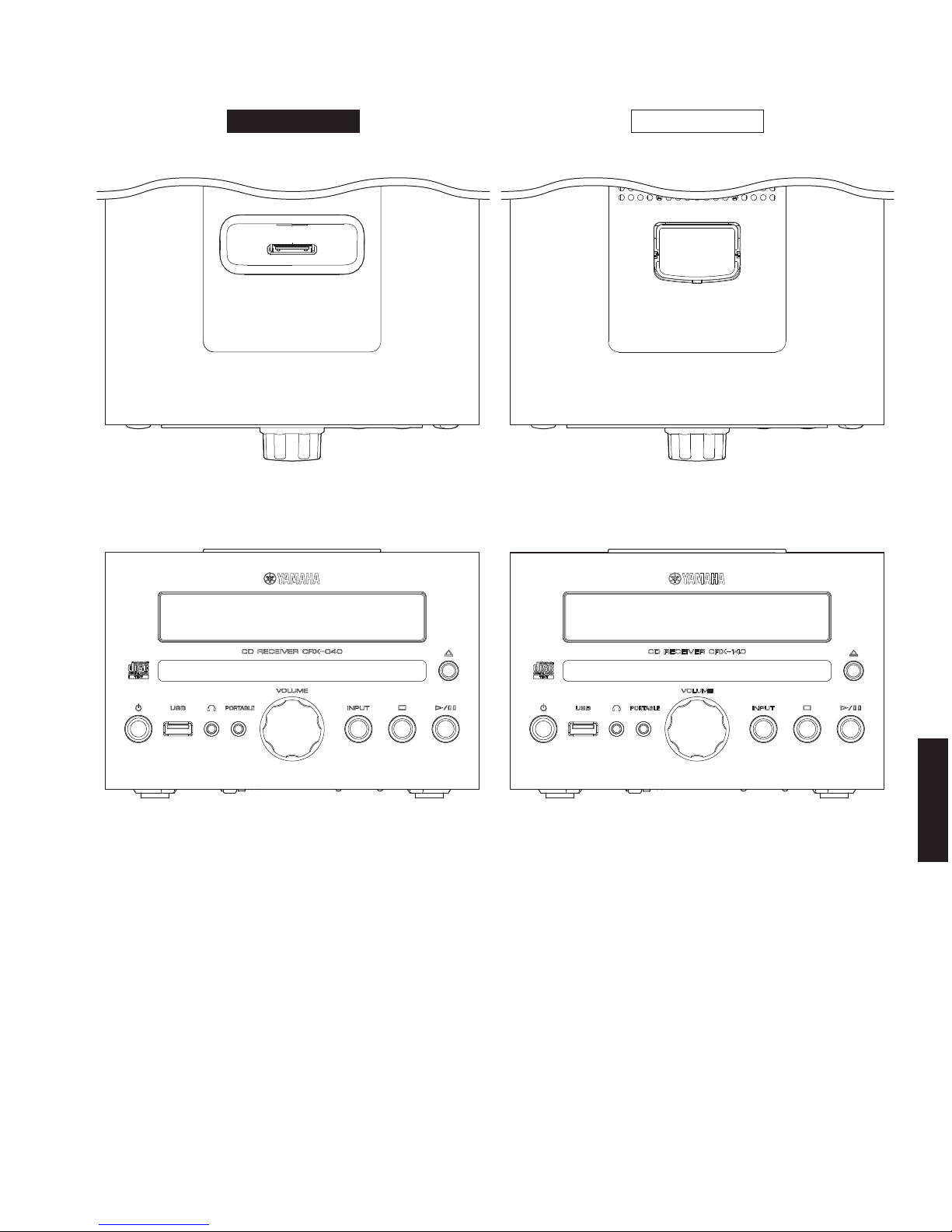
■ FRONT PANELS
CRX-140CRX-040
8
CRX-040/CRX-140/NS-BP80
CRX-040/CRX-140/
NS-BP80
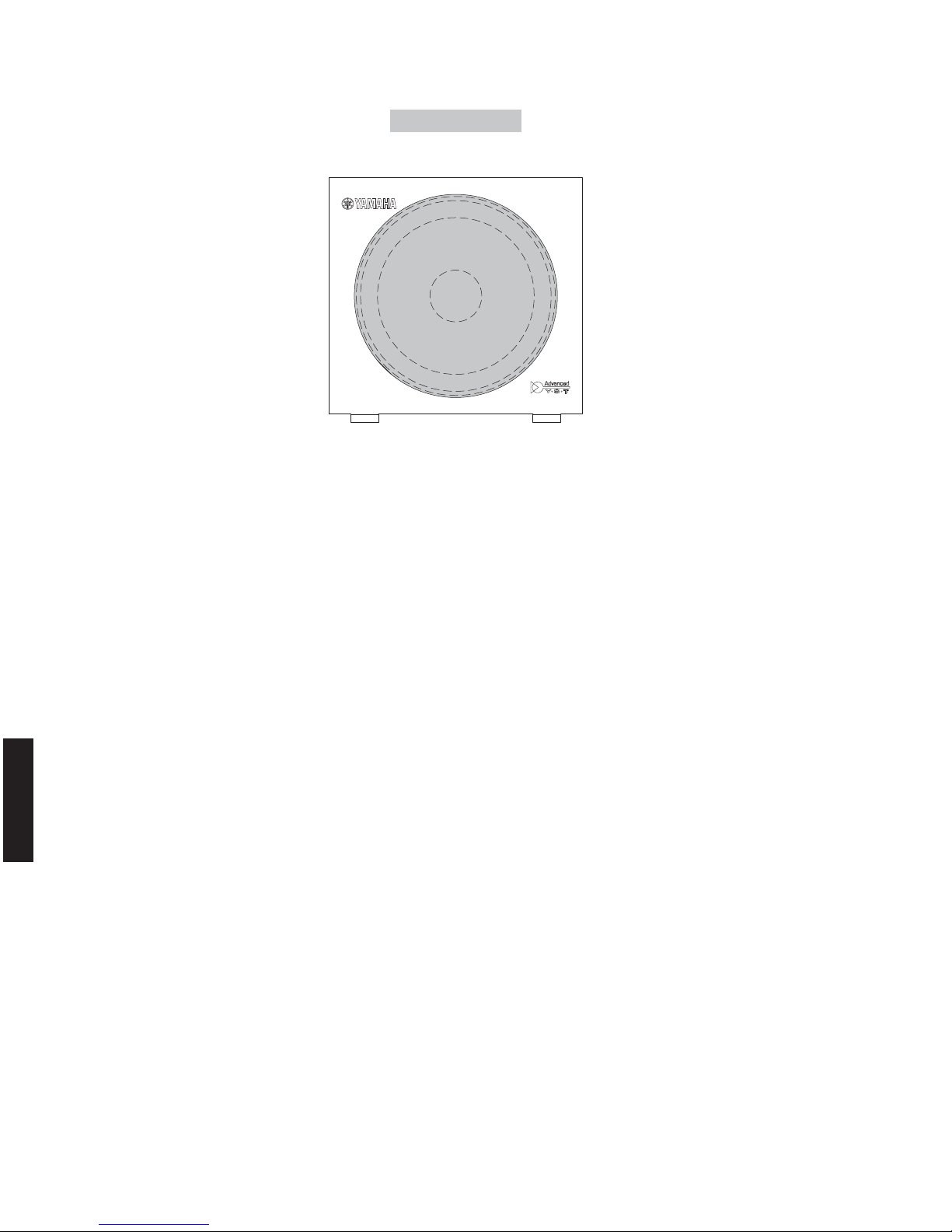
U, T, K, A, B, G, L, V, J models
NS-BP80

9
CRX-040/CRX-140/NS-BP80
CRX-040/CRX-140/
NS-BP80
● Color Variations /
カラーバリエーション
OR : Orange color /
オレンジ
WH : White color /
ホワイト
LG : Light Gray color /
ライトグレー
DG : Dark Gray color /
ダークグレー
LB : Light Blue color /
ライトブルー
DB : Dark Blue color /
ダークブルー
RE : Red color /
レッド
PI : Pink color /
ピンク
DN : Dark Green color /
ダークグリーン
BR : Brown color /
ブラウン
10
CRX-040/CRX-140/NS-BP80
CRX-040/CRX-140/
NS-BP80
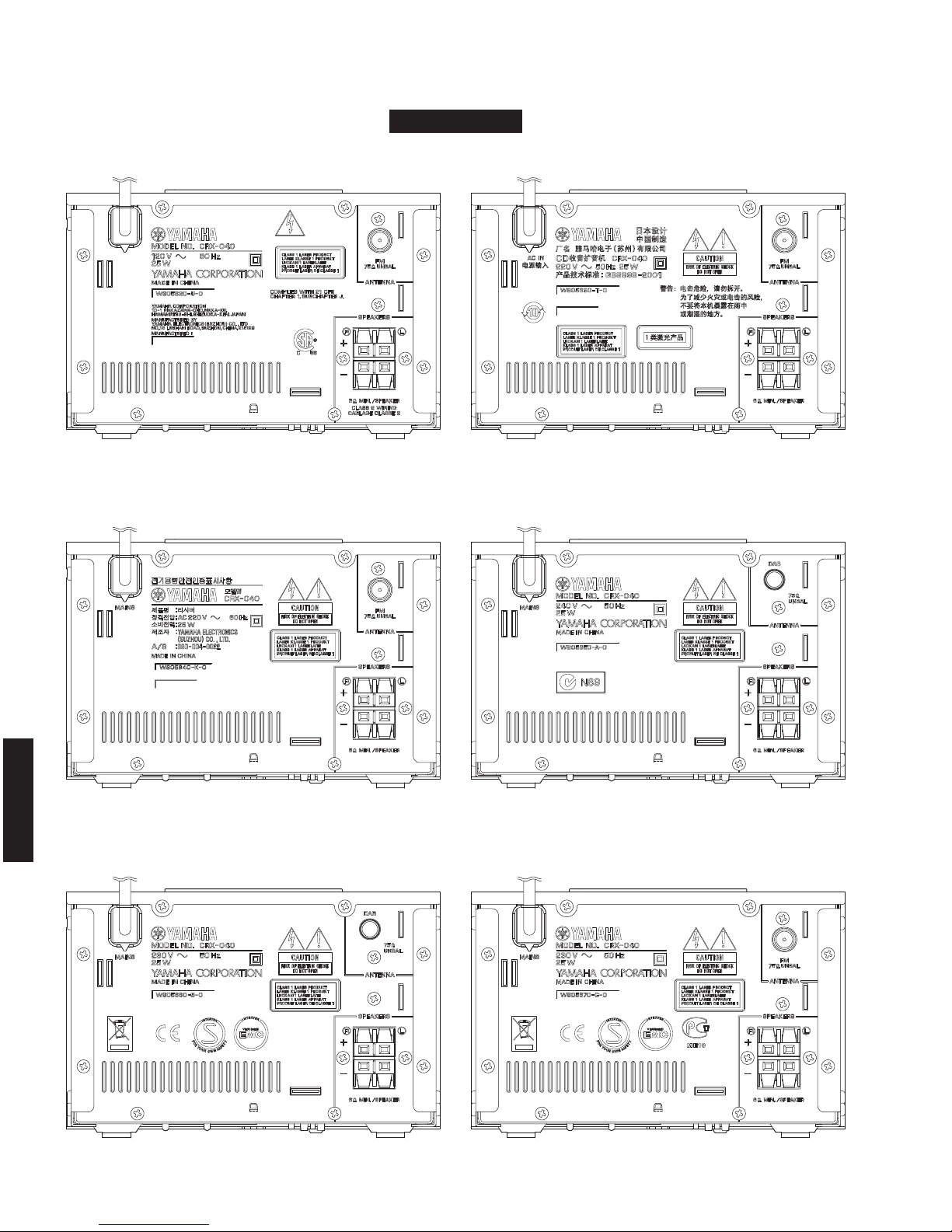
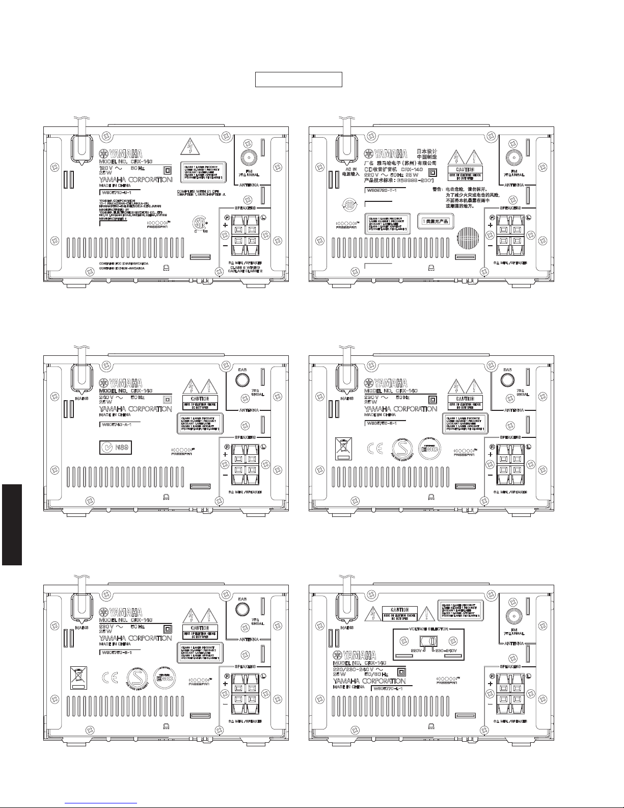
■ REAR PANELS
U model
K model
B model
T model
A model
G model
CRX-040

11
CRX-040/CRX-140/NS-BP80
CRX-040/CRX-140/
NS-BP80
L model
J model
V model
CRX-040
12
CRX-040/CRX-140/NS-BP80
CRX-040/CRX-140/
NS-BP80
U model
A model
G model
T model
B model
L model
CRX-140
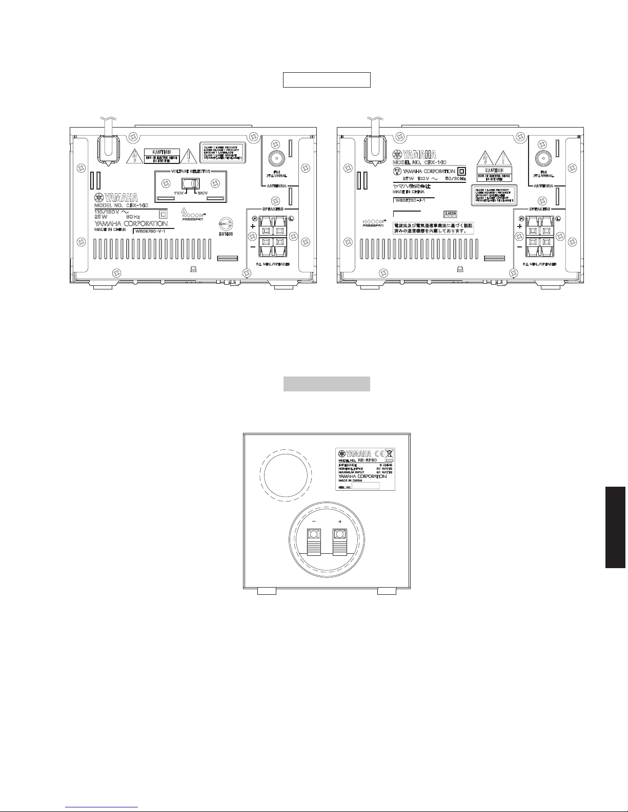
13
CRX-040/CRX-140/NS-BP80
CRX-040/CRX-140/
NS-BP80
U, T, K, A, B, G, L, V, J models
V model J model
CRX-140
NS-BP80
14
CRX-040/CRX-140/NS-BP80
CRX-040/CRX-140/
NS-BP80
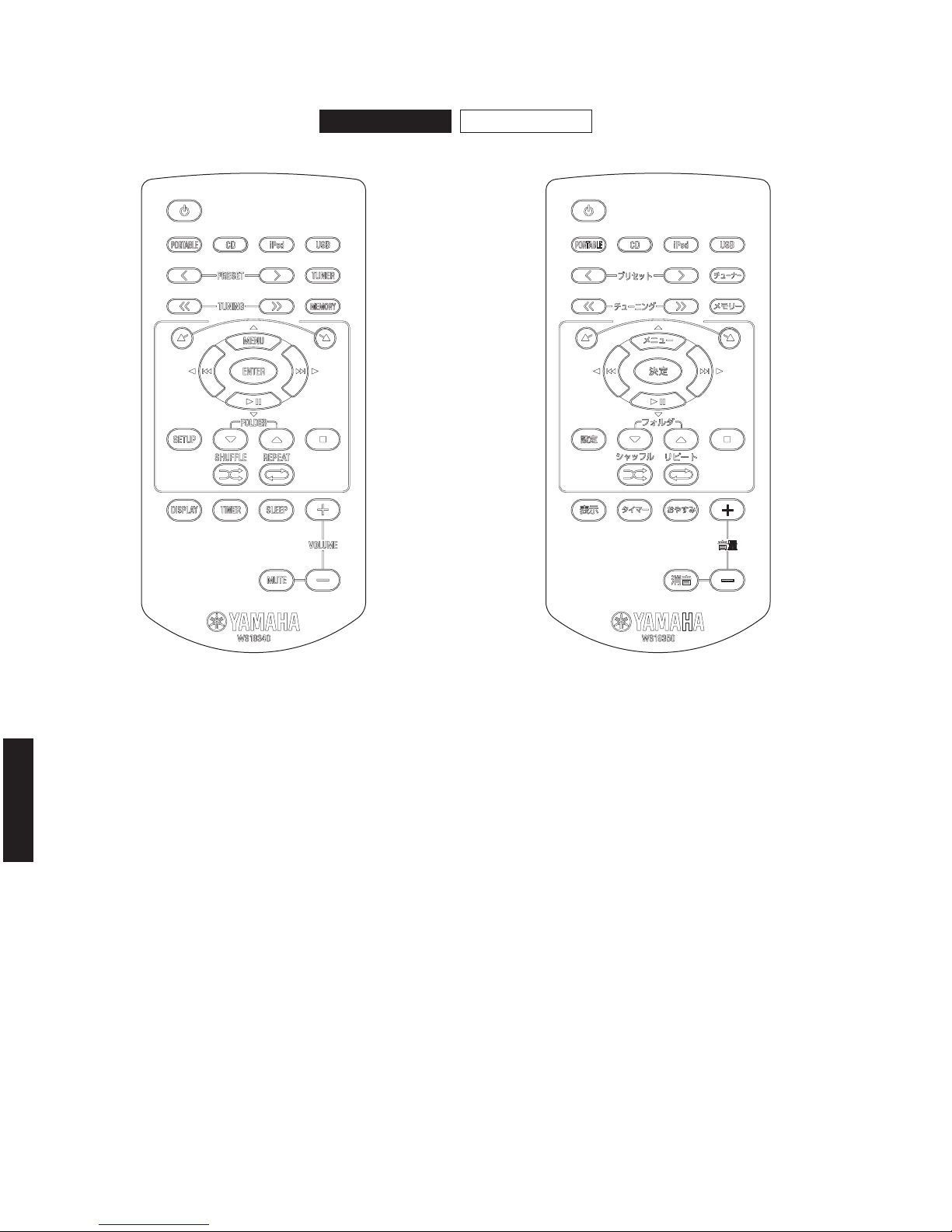
■ REMOTE CONTROL PANELS
U, T, K, A, B, G, L, V models J model
CRX-040 CRX-140

15
CRX-040/CRX-140/NS-BP80
CRX-040/CRX-140/
NS-BP80
■ SPECIFICATIONS /
参考仕様
■ Amplifier Section /
アンプ部
Maximum Power /
実用最大出力
(JEITA, 1 kHz, 10 % THD, 6 ohms)
SP OUT .........................................................................15 W + 15 W
Minimum RMS Output Power /
定格出力
(1 kHz, 0.9 % THD, 6 ohms)
SP OUT .........................................................................13 W + 13 W
Input Sensitivity/Input Impedance /
入力感度/入力インピーダンス
(1 kHz, 20 W)
PORTABLE ........................................................ 450 mV / 22 k-ohms
Maximum Input Signal Level /
最大許容入力
(1 kHz, 0.5 % THD)
PORTABLE ...................................................................2.5 V or more
Output Level/Output Impedance /
出力電圧/出力インピーダンス
(1 kHz, 450 mV, 32 ohms)
Headphone ........................................................ 270 mV / 100 ohms
Signal to Noise Ratio /
信号対雑音比
(Portable, IHF-A network, Input shorted 450 mV)
SP OUT ...................................................................... 85 dB or more
Total Harmonic Distortion /
全高調波歪率
(Portable, 20 kHz LPF, CD etc., 1 kHz, 1 W)
SP OUT .......................................................................0.05 % or less
Tone Control /
トーンコントロール特性
(SP OUT)
BASS (100 Hz) ....................................................................... ± 6 dB
TREBLE (10 kHz) ................................................................... ± 6 dB
■ Tuner Section /
チューナー部
FM Tuning Range /
FM 受信周波数範囲
U model ...............................................................87.5 to 107.9 MHz
T, K, A, B, G, L, V models ................................87.50 to 108.00 MHz
J model ..................................................................76.0 to 90.0 MHz
■ CD Section /
CD 部
Playback System /
再生システム
Media .......................................................................... CD, CD-R/RW
Audio format .....................................................CD-DA, MP3, WMA)
Audio Performance /
オーディオ部再生
DAC ...........................................................................192 kHz/24 bit
■ Input/Output Section /
入出力部
Input Terminal /
入力端子
Analog Audio
PORTABLE (mini jack) ................................................................x 1
Other
USB (1.1, full speed) ..................................................................x 1
Audio format /
オーディオフォーマット
....................MP3, WMA
iPod (CRX-040) ..........................................................................x 1
Supported iPod /
対応 iPod
........................iPod (5th generation)
iPod classic
iPod nano
iPod touch
Output Terminal /
出力端子
Analog Audio
SPEAKERS ................................................................................L/R
Headphone ................................................................................x 1
Charging Terminal /
充電端子
Transmitter (for charging iPod) .....................................................x 1
■ Transmitter Section /
トランスミッター部
(YIT-W11TX)
Frequency /
周波数
................................................................ 2.4 GHz
Transmission range /
通信可能距離
..................................................................Approx. 10 m (32.8 ft)
(without interference /
妨害のない時
)
Number of units which can be simultaneously transmitted to /
同時接続台数
...............................................................Up to 7 units /
最大7台
(depending on the circumstances /
場所や状況により異なる
)
■ Speaker Section /
スピーカー部
(NS-BP80)
Type / 型式 ............Advanced Yamaha Active Servo Technology
アドバンスドヤマハ アクティヴ サーボ テクノロジー
Driver /
スピーカーユニット
.................................................... Full-range 10 cm (3/8”) cone type
Non-magnetic shielding type
非防磁型
Frequency Response /
再生周波数帯域
...................................................................50 Hz to 18 kHz (-10 dB)
50 Hz to 24 kHz (-30 dB)
Input Terminal /
入力端子
........................Push type /
プッシュ型
■ General /
総合
Power Supply /
電源電圧
U model ..................................................................AC 120 V, 60 Hz
T model ................................................................... AC 220 V, 50 Hz
K model .................................................................. AC 220 V, 60 Hz
A model .................................................................. AC 240 V, 50 Hz
B, G models ............................................................ AC 230 V, 50 Hz
L model ............................................... AC 220/230–240 V, 50/60 Hz
V model ............................................................ AC 110/120 V, 60 Hz
J model .............................................................. AC 100 V, 50/60 Hz
Power Consumption /
消費電力
.................................................................................................. 25 W
Standby Power Consumption (reference data) /
待機時消費電力(参考値)
....................................................................................Less than 1 W
Dimensions (W x H x D) /
寸法(幅 × 高さ × 奥行き)
[CRX-040/CRX-140]
.............................. 180 x 120 x 309 mm (7-1/8" x 4-3/4" x 12-1/8")
[NS-BP80]
.............................. 122 x 118 x 287 mm (4-3/4" x 4-5/8" x 11-1/4")
Weight / 質量
[CRX-040]
.............................................................................. 3.6 kg (7.9 lbs.)
[CRX-040]
.............................................................................. 1.4 kg (3.1 lbs.)
16
CRX-040/CRX-140/NS-BP80
CRX-040/CRX-140/
NS-BP80
U ... U.S.A. and Canadian model
T......................... Chinese model
K .......................... Korean model
A ..................... Australian model
B ........................... British model
G ......................European model
L......................Singapore model
V ...........................Taiwan model
J ....................... Japanese model
Finish /
仕上げ
OR (Orange color) ............................U, T, K, A, B, G, L, V, J models
WH (White color) ...............................U, T, K, A, B, G, L, V, J models
LG (Light Gray color) ........................ U, T, K, A, B, G, L, V, J models
DG (Dark Gray color) ........................U, T, K, A, B, G, L, V, J models
LB (Light Blue color) ......................... U, T, K, A, B, G, L, V, J models
DB (Dark Blue color) .........................U, T, K, A, B, G, L, V, J models
RE (Red color) ..................................U, T, K, A, B, G, L, V, J models
PI (Pink color) ...................................U, T, K, A, B, G, L, V, J models
DN (Dark Green color) ......................U, T, K, A, B, G, L, V, J models
BR (Brown color) ...............................U, T, K, A, B, G, L, V, J models
Accessories /
付属品
[CRX-040]
Remote control ...........................................................................x 1
Lithium batteries (CR2025) ........................................................x 2
Indoor FM antenna (1.4 m) (U, T, G, L, V, J models) ..................x 1
DOCK cover ...............................................................................x 1
[CRX-140]
Remote control ...........................................................................x 1
Lithium batteries (CR2025) ........................................................x 2
Indoor FM antenna (1.4 m) (U, T, G, L, V, J models) ..................x 1
Transmitter (YIT-W11TX Ver. D31i) .............................................x 1
[NS-BP80]
Speaker cable (1.5 m) ...............................................................x 2
* Specifications are subject to change without notice due to
product improvements.
※ 参考仕様および外観は予告なく変更されることがあります。
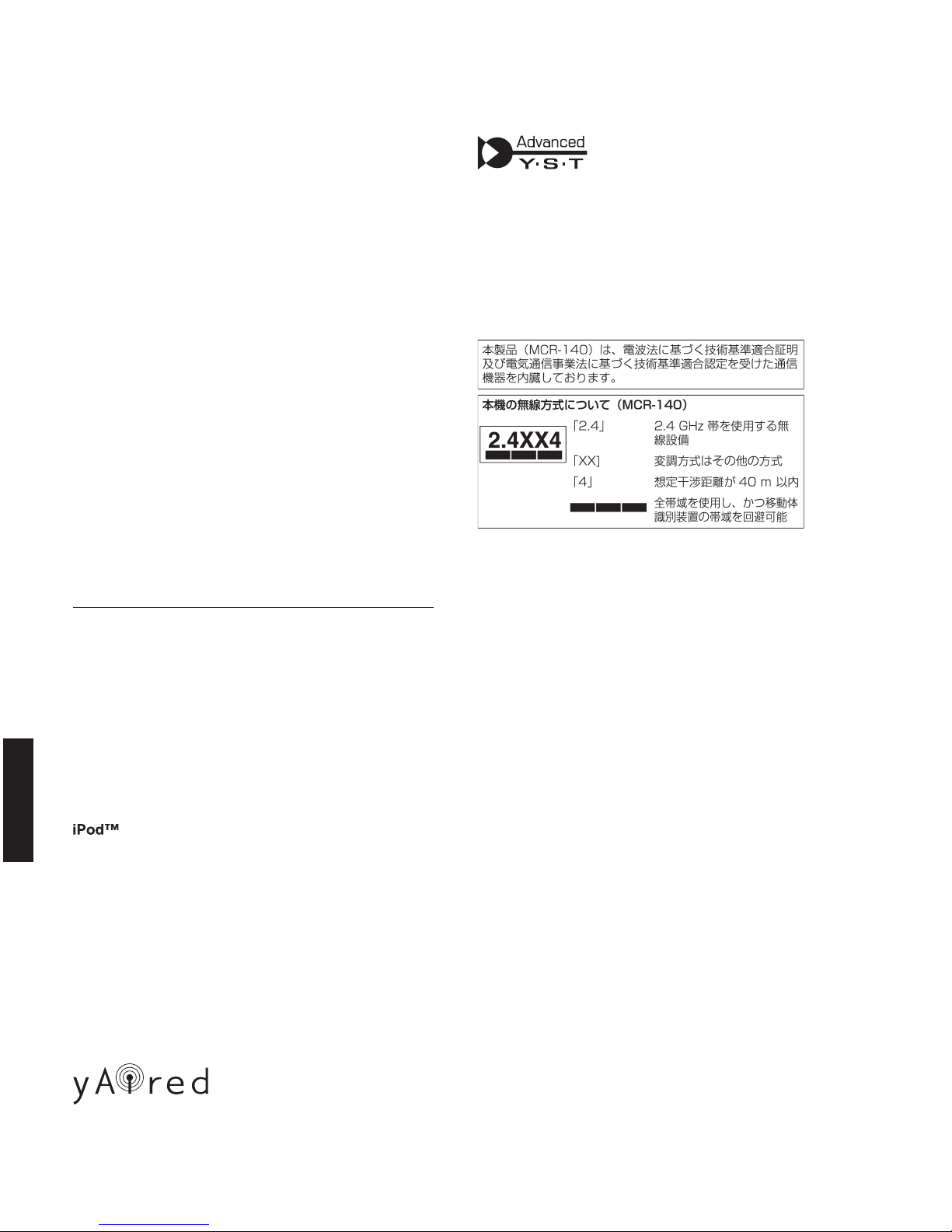
Advanced Yamaha Active Servo Technology II
Advanced Yamaha Active Servo Technology is a unique system to let the
speaker unit have a perfectly linear motion by the speaker and amplifier
combination.
アドバンスドヤマハアクティブサーボテクノロジーII
アドバンスドヤマハアクティブサーボテクノロジーは、スピーカーとアン
プの組み合わせにより振動板を効率よくスムーズに動かし最大音圧時のリ
ニアリティを大幅に改善したユニークなシステムです。
iPod is a trademark of Apple Inc., registered in the U.S. and other countries.
“Made for iPod” means that an electronic accessory has been designed to
connect specifically to iPod and has been certified by the developer to meet
Apple performance standards.
Apple is not responsible for the operation of this device or its compliance
with safety and regulatory standards.
iPod は、米国およびその他の国々で登録されている AppleInc.の商標です。
「MadeforiPod」とは、iPod 専用に接続するよう設計され、アップルが定
める性能基準を満たしているとデベロッパーによって認定された電子アク
セサリーであることを示します。
アップルは、これらの機器操作または、安全規制基準に関する一切の責任
を負いません。
Real-time uncompressed music transfer without sound degradation is
realized by Yamaha original digital wireless transfer technology, yAired.
ヤマハ独自のデジタルワイヤレス伝送技術
「AirWired」により、非圧縮で音質劣化のない音楽をリアルタイムで再生。
17
CRX-040/CRX-140/NS-BP80
CRX-040/CRX-140/
NS-BP80
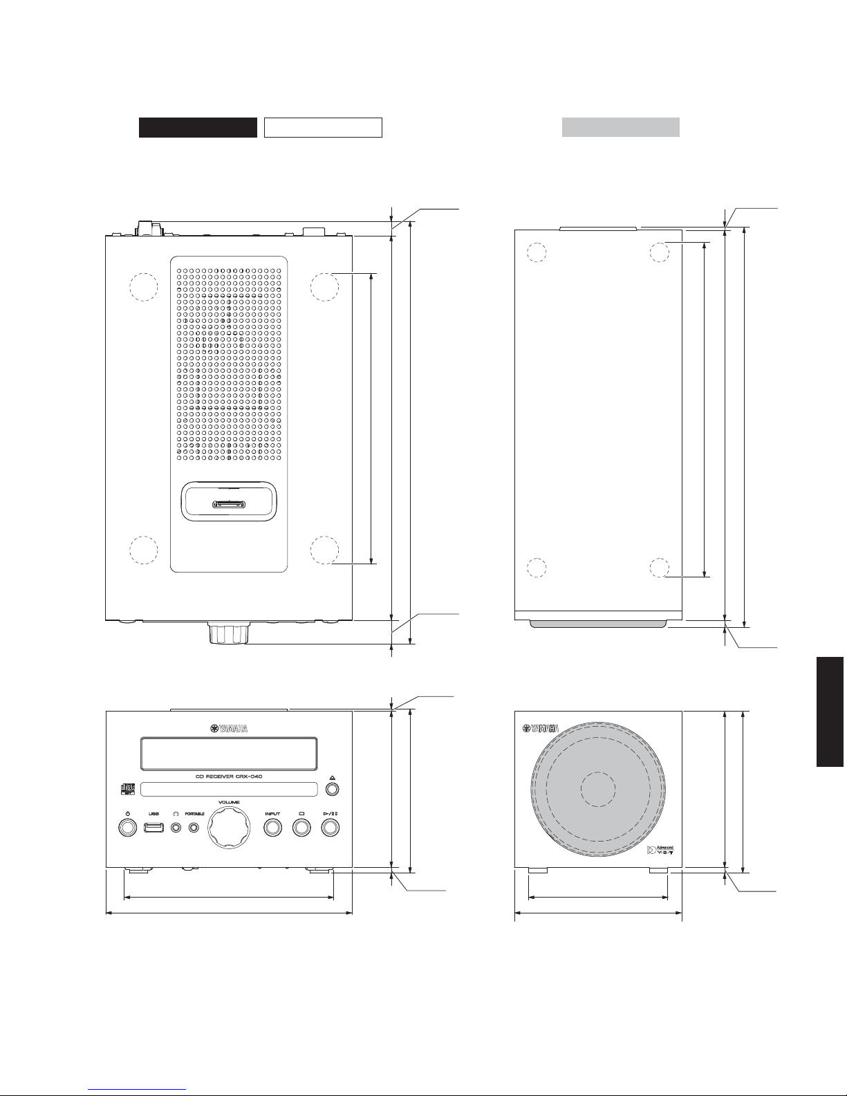
Top view
Front view
Front view
Top view
180 (7-1/4")
155 (6-1/8")
112 (4-3/8")
120 (4-3/4")
6 (1/4")
287 (11-1/4")
215 (8-1/2")
264 (10-3/8")
17 (5/8")
120 (4-3/4")
102 (4")
114 (4-1/2")
118 (4-5/8")
4 (1/8")
2 (1/8")
5 (1/4")
2.5 (1/8")
5 (1/4")
240 (9-1/2")
287 (11-1/4")
279.5 (11")
• DIMENSIONS /
寸法図
Unit: mm (inch)
単位:mm(インチ)
Unit: mm (inch)
単位:mm(インチ)
CRX-040 CRX-140
NS-BP80

18
CRX-040/CRX-140/NS-BP80
CRX-040/CRX-140/
NS-BP80
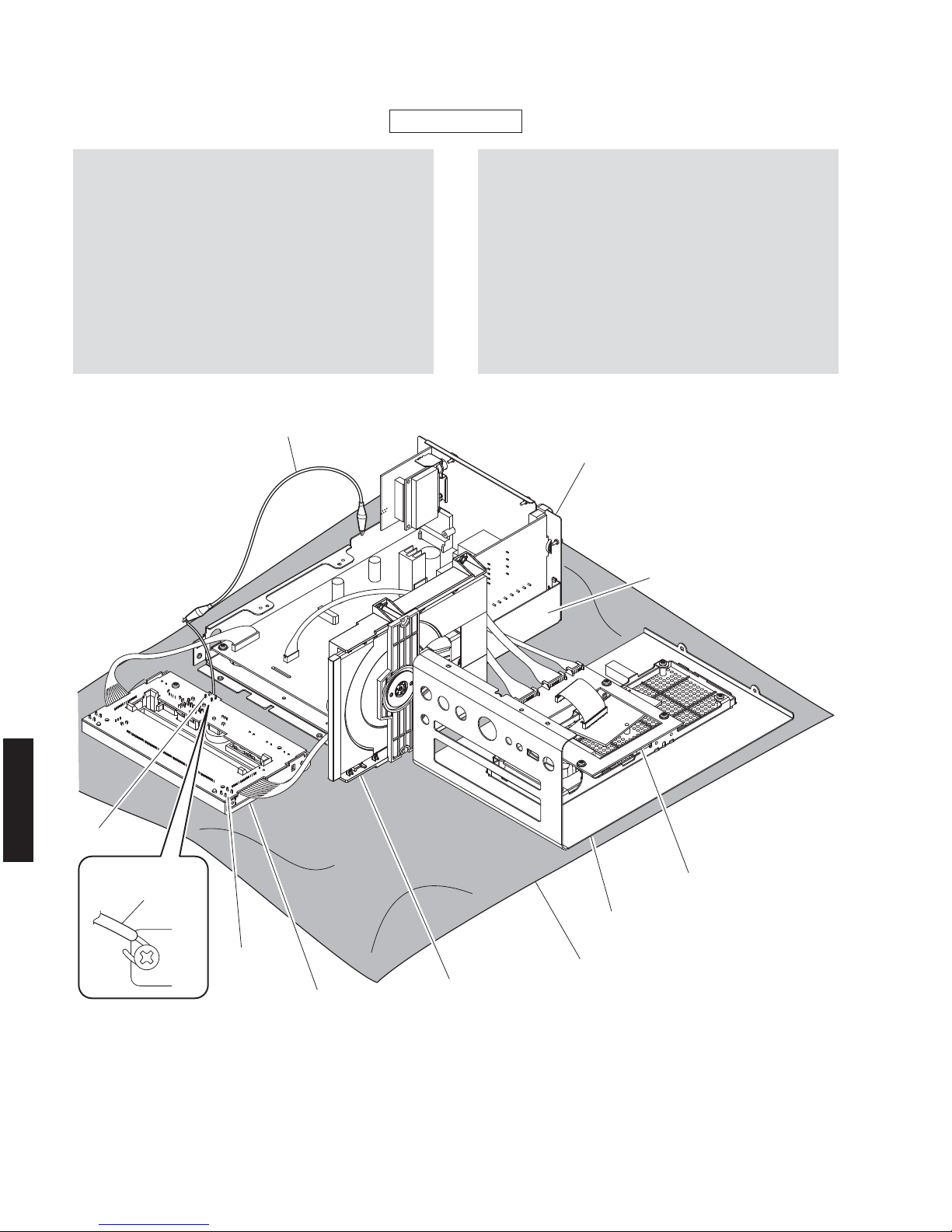
Top view
Front view
Rear view
DAB MODULE (A, B models)
MAIN (2) P.C.B. (A, B models)
FM TUNER (U, T, K, G, L, V, J models)
MAIN (1) P.C.B.
SUB (3) P.C.B. (L, V models)
SUB (2) P.C.B.
LOADER MECHANISM UNIT
CONNECTOR (2) P.C.B. (CRX-140)
MAIN (3) P.C.B. (CRX-040)
CONNECTOR (1) P.C.B. (CRX-140)
SUB (1) P.C.B.
1
2
3
4
5
6
7
8
9
10
98
7
1
10
35462
CRX-040 CRX-140
■ INTERNAL VIEW
19
CRX-040/CRX-140/NS-BP80
CRX-040/CRX-140/
NS-BP80
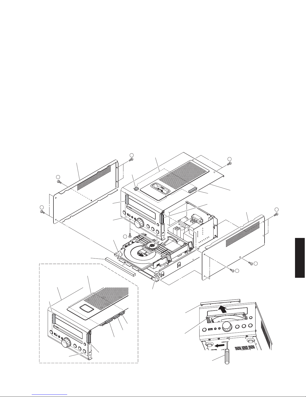
CB702
CB703
CB802
CB801
CB604
CB603
CB602
CB801
CB802
MAIN (3) P.C.B.
CONNECTOR (1) P.C.B.
SUB (1) P.C.B.
SUB (1) P.C.B.
Side cover L
サイドカバーL
Front panel unit
フロントパネルユニット
Front panel unit
フロントパネルユニット
Side cover R
サイドカバーR
2
2
3
3
2
1
1
1
How to manually open the disc tray
ディスクトレイを開ける方法
CRX-140
Flatblade screwdriver
マイナスドライバー
Lid
リッド
Lid
リッド
Disc tray
ディスクトレイ
Hook
フック
Hook
フック
■ DISASSEMBLY PROCEDURES /
分解手順
Disconnect the power cable from the AC outlet.
1. Removal of Front Panel Unit
a. Using a flatblade screwdriver, move the slider at the
bottom in the direction of the arrow shown above.
(Fig. 1)
Open the disc tray, remove the lid and close the disc
tray. (Fig. 1)
b. Remove 5 screws (①), and remove the side cover R.
(Fig. 1)
c. Remove 5 screws (②), and remove the side cover L.
(Fig. 1)
d. Remove 4 screws (③). (Fig. 1)
e. Remove CB801-802. (Fig. 1)
f. Remove CB702-703. (Fig. 1) (CRX-040)
g. Remove CB602-604. (Fig. 1) (CRX-140)
h. Release 2 hooks, and remove the front panel unit.
(Fig. 1)
AC 電源コンセントから、電源コードを抜いてください。
1. フロントパネルユニットの外し方
a. マイナスドライバーで底面のスライダーを上図の矢印
の方向に動かします。(Fig.1)
ディスクトレイを開けてリッドを取り外し、ディスク
トレイを閉じます。(Fig.1)
b. ①のネジ 5 本を外し、サイドカバー R を取り外します。
(Fig.1)
c. ②のネジ 5 本を外し、サイドカバー L を取り外します。
(Fig.1)
d. ③のネジ 4 本を外します。(Fig.1)
e. CB801 〜 802 を外します。(Fig.1)
f. CB702 〜 703 を外します。(Fig.1)(CRX-040)
g. CB602 〜 604 を外します。(Fig.1)(CRX-140)
h. フック 2 箇所を外し、フロントパネルユニットを取り
外します。(Fig.1)
Fig. 1
20
CRX-040/CRX-140/NS-BP80
CRX-040/CRX-140/
NS-BP80
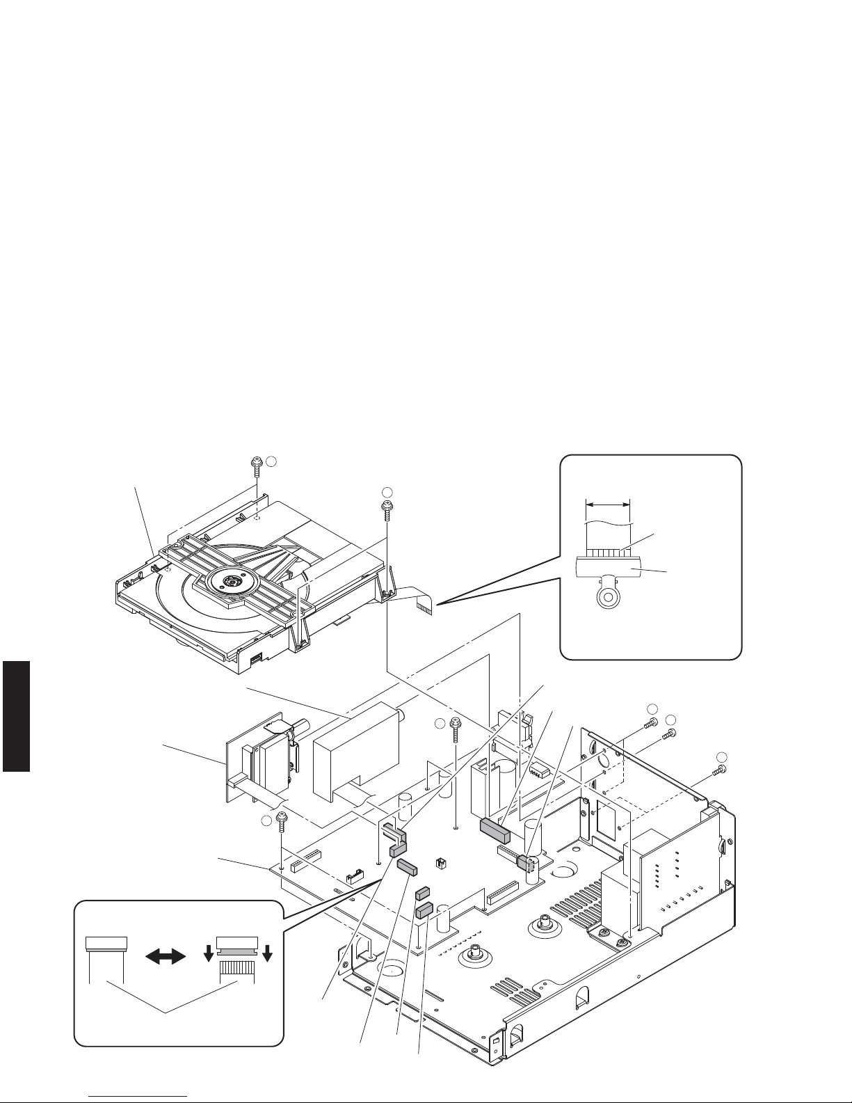
4
4
5
6
7
9
8
Flexible flat cable
カード電線
CB501
(U, T, K, G, L, V, J models)
Locked Unlocked
(U, T, K, G, L, V, J models)
CB251
CB101
CB103
MAIN (1) P.C.B.
FM tuner
FMチューナー
(A, B models)
(A, B models)
DAB module
DABモジュール
Loader mechanism unit
ローダーメカユニット
Use a clip or other item to ground
the unit.
クリップ 等 で アースし てくだ さ い 。
Clip
クリップ
Terminal side
端子面
17 mm
(0.67")
CB252
CB501
CB502
W501
Fig. 2
2. ローダーメカユニットの外し方
a. ④のネジ 4本を外します。(Fig.2)
b. CB502、W501 を外します。(Fig.2)
c. ロックを解除して CB501 を外し、カード電線の端子
面をクリップ等でアースします。(Fig.2)
d. ローダーメカユニットを取り外します。(Fig.2)
3. FM チューナーの外し方
a. ⑤のネジ 2 本を外します。(Fig.2)
b. CB251 を外します。(Fig.2)
c. FM チューナーを取り外します。(Fig.2)
4. MAIN(1)P.C.B. の外し方
a. ⑦ のネジ 2 本、⑧のネジ 3 本、⑨ のネジ 3 本を外し
ます。(Fig.2)
b. CB101、CB103 を外します。(Fig.2)
c. MAIN(1)P.C.B. を取り外します。(Fig.2)
2. Removal of Loader Mechanism Unit
a. Remove 4 screws (④). (Fig. 2)
b. Remove CB502 and W501. (Fig. 2)
c. Unlock and remove CB4 and ground the terminal side
of the flexible flat cable with a clip or the like. (Fig. 2)
d. Remove the loader mechanism unit. (Fig. 2)
3-1. Removal of FM tuner (U, T, K, G, L, V, J models)
a. Remove 2 screws (⑤). (Fig. 2)
b. Remove CB251. (Fig. 2)
c. Remove the FM tuner. (Fig. 2)
3-2. Removal of DAB module (A, B models)
a. Remove 2 screws (⑥). (Fig. 2)
b. Remove CB252. (Fig. 2)
c. Remove the DAB module. (Fig. 2)
4. Removal of MAIN (1) P.C.B.
a. Remove 2 screws (⑦), 3 screws (⑧) and 3 screws
(⑨). (Fig. 2)
b. Remove CB101 and CB103. (Fig. 2)
c. Remove the MAIN (1) P.C.B.. (Fig. 2)
21
CRX-040/CRX-140/NS-BP80
CRX-040/CRX-140/
NS-BP80
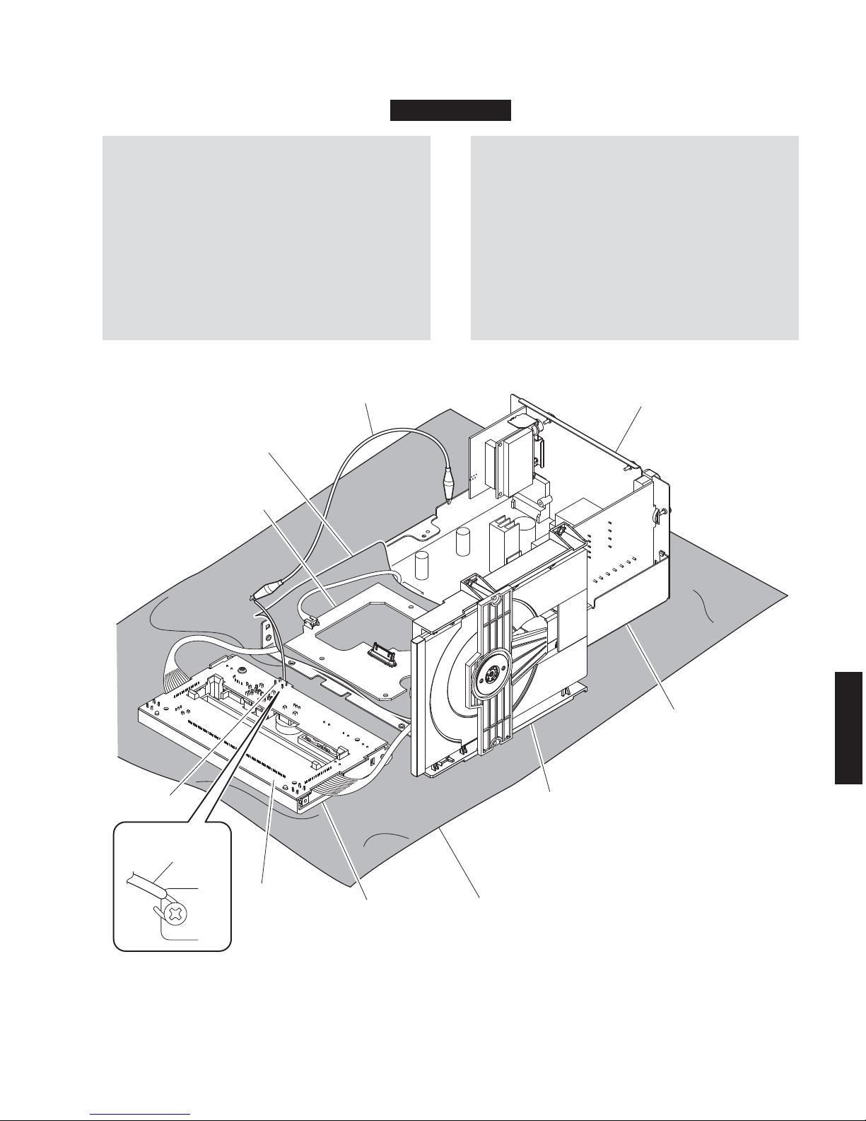
When checking the P.C.B.s:
• Spread the rubber sheet and the cloth. Then place
this unit on the cloth and check it. (Fig. 3)
• When connecting the flexible flat cable, be careful
with polarity.
• Connect the ground point (ST801) of the SUB (1)
P.C.B. to the chassis with a ground lead or the like.
(Fig. 3)
• Reconnect all cables (connectors) that have been
disconnected.
P.C.B. をチェックする場合には:
・ ゴムシートと布を敷き、その上に本機を置いてチェッ
クします。(Fig.3)
・ 外したケーブル(コネクター)をすべて接続します。
・ SUB(1)P.C.B.のアース(ST801)をアース線等でシャー
シに接続してください。(Fig.3)
・ フラットケーブルを接続する際、極性に注意してく
ださい。
Rubber sheet and the cloth
ゴ ム シ ートと布
Rubber sheet and the cloth
ゴ ム シ ートと布
Ground lead
アース線
MAIN (3) P.C.B.
SUB (1) P.C.B.
ST801
ST801
Loader mechanism unit
ローダーメカユニット
SUB panel unit
SUBパネルユニット
Rear panel
リアパ ネ ル
Chassis
シャーシ
Ground lead
アース線
CRX-040
Fig. 3
22
CRX-040/CRX-140/NS-BP80
CRX-040/CRX-140/
NS-BP80
When checking the P.C.B.s:
• Spread the rubber sheet and the cloth. Then place
this unit on the cloth and check it. (Fig. 4)
• When connecting the flexible flat cable, be careful
with polarity.
• Connect the ground point (ST801) of the SUB (1)
P.C.B. to the chassis with a ground lead or the like.
(Fig. 4)
• Reconnect all cables (connectors) that have been
disconnected.
P.C.B. をチェックする場合には:
・ ゴムシートと布を敷き、その上に本機を置いてチェッ
クします。(Fig.4)
・ 外したケーブル(コネクター)をすべて接続します。
・ SUB(1)P.C.B.のアース(ST801)をアース線等でシャー
シに接続してください。(Fig.4)
・ フラットケーブルを接続する際、極性に注意してく
ださい。
Rubber sheet and the cloth
ゴ ム シ ートと布
Ground lead
アース線
CONNECTOR (1) P.C.B.
SUB (1) P.C.B.
ST801
Loader mechanism unit
ローダーメカユニット
SUB panel unit
SUBパネルユニット
Front panel unit
フロントパネルユニット
Rear panel
リアパ ネ ル
Chassis
シャーシ
Ground lead
アース線
CRX-140
Fig. 4
23
CRX-040/CRX-140/NS-BP80
CRX-040/CRX-140/
NS-BP80
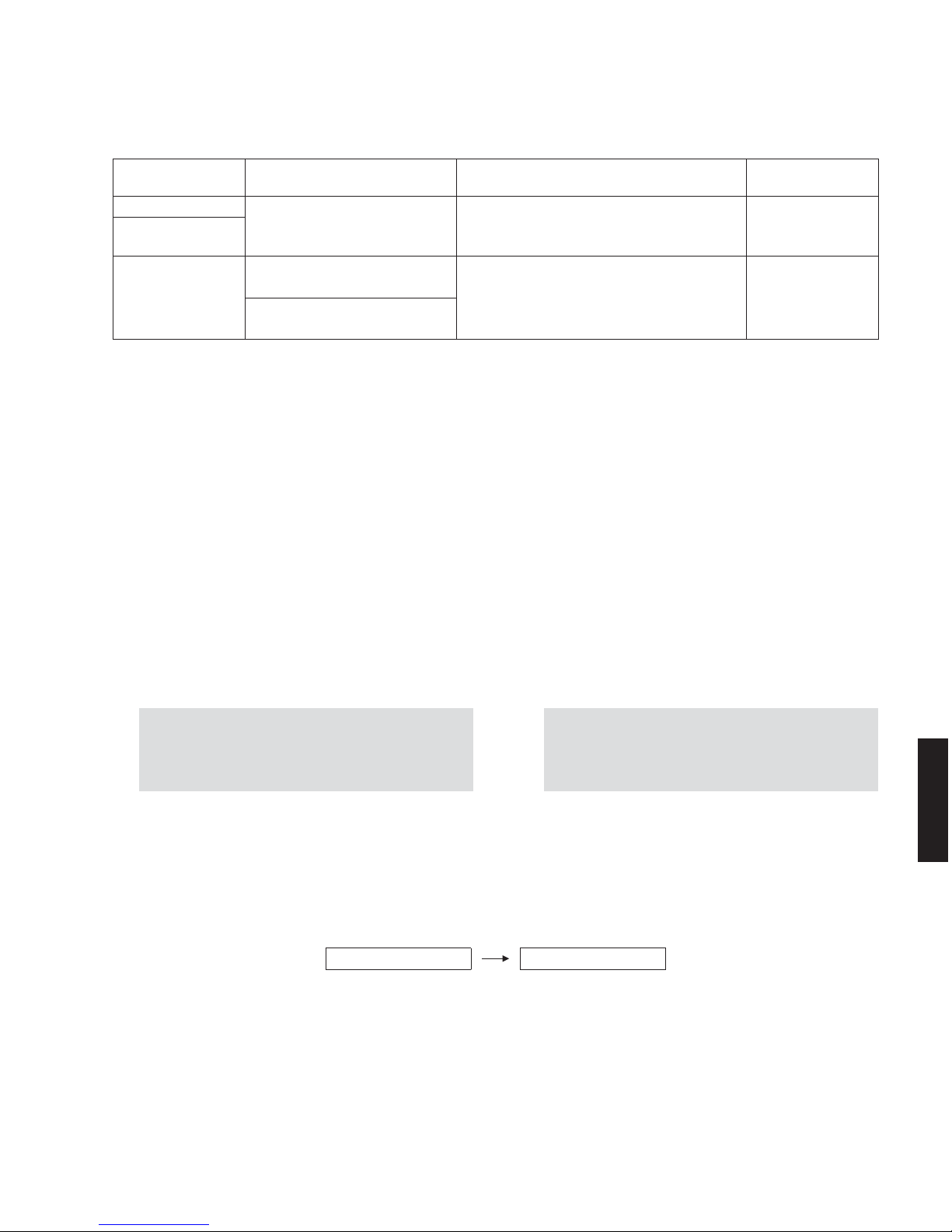
C-1PRESETINH C-2PRESETRSRV
下記の部品を交換した場合、ファームウェアを最新バー
ジョンにアップデートする必要があります。
When the following parts are replaced, the firmware must
be updated to the latest version.
Replaced Parts
交換した部品
Firmware
ファームウェア
Update method
アップデートの方法
Model
モデル名
MAIN P.C.B.
Main microprocessor firmware
メインマイコンファームウェア
Updating the main microprocessor firmware
メインマイコンファームウェアのアップデート
MCR-040/MCR-140
Main microprocessor
(IC267, MAIN P.C.B.)
AW-CARD P.C.B.
Wireless Module Firmware
ワイヤレスモジュールファームウエア
Updating the Wireless Module Firmware
and the AirWired microprocessor Firmware
ワイヤレスモジュールファームウエアと
AirWired マイコンファームウエアのアップデート
MCR-140
AirWired microprocessor Firmware
AirWired マイコンファームウエア
■ UPDATING FIRMWARE /
ファームウェアのアップデート
● ファームウェアのバージョンとチェックサムの確認
ファームウエアのアップデートの前後に、ファーム
ウエアのバージョンとチェックサムをダイアグで確
認します。
ダイアグを起動し、“1.ROMVER/SUM” を選択します。
サブメニューでファームウェアのバージョンと
チェックサムを表示し、それらを書きとめます。
(「ダイアグ」参照)
※ アップデート後、ファームウェアのバージョンが
書き込まれたものと異なる場合、アップデートの
操作を最初からやり直してください。
● バックアップ IC の初期化
ファームウェアのアップデート後、必ず下記の手順
でバックアップ IC の初期化を行ってください。で
なければ、設定情報(チューナープリセット、時計)
が正常に記憶されません。
ダイアグを起動し、“C.FACTORYPRESET” を選択しま
す。(「ダイアグ」参照)
サブメニュー “C-2PRESETRSRV” を選択し、電源を
一度切ってから、もう一度電源を入れるとバックアッ
プ IC が初期化されます。
● Confirmation of firmware version and checksum
Before and after updating the firmware, check the
firmware version and checksum by using the selfdiagnostic function menu.
Start up the self-diagnostic function and select “1.
ROM VER/SUM” menu.
Using the sub-menu, have the firmware version and
checksum displayed, and note down them.
(See “SELF-DIAGNOSTIC FUNCTION”)
* When the firmware version is different from
written one after updating, perform the updating
procedure again from the beginning.
● Initializing the back-up IC
Be sure to initialize the back-up IC after updating
the firmware by the following procedure, otherwise
the set up information (tuner preset, clock) can not
be memorized properly.
Start up the self-diagnostic function and select “C.
FACTORY PRESET” menu. (See “SELF-DIAGNOSTIC
FUNCTION”)
Select “C-2 PRESET RSRV” sub-menu and turn off
the power once and turn on the power again. Then
the buck-up IC is initialized.

24
CRX-040/CRX-140/NS-BP80
CRX-040/CRX-140/
NS-BP80
PinNo.2RxD PinNo.2RxD
PinNo.3TxD PinNo.3TxD
PinNo.5GND PinNo.5GND
PinNo.7RTS PinNo.7RTS
PinNo.8CTS PinNo.8CTS
Pin No.2 RxD Pin No.2 RxD
Pin No.3 TxD Pin No.3 TxD
Pin No.5 GND Pin No.5 GND
Pin No.7 RTS Pin No.7 RTS
Pin No.8 CTS Pin No.8 CTS
● 必要なツール
・ プログラム書き込み用プログラム....... FlashSta.exe
・ ファームウェア
メインマイコンファームウェア(CRX-040/CRX-140)
.............................................................CRXx40xxxx.mot
CRXx40xxx.id
ワイヤレスモジュールファームウェア(CRX-140)
...................................................... uawfirmupxxxx.mot
uawfirmupxxxx.id
AirWired マイコンファームウェア(CRX-140)
............................................................uawcardxxxx.mot
uawcardxxxx.id
・ RS232C クロスケーブル “D-sub9pin メス”
(仕様)
● Required tools
• Firmware downloader program ........ FlashSta.exe
• Firmware
Main microprocessor firmware (CRX-040/CRX-140)
............................................. CRX_x40_xxxx.mot
CRX_x40_xxx.id
Wireless module firmware (CRX-140)
......................................... uaw_firmup_xxxx.mot
uaw_firmup_xxxx.id
AirWired microprocessor firmware (CRX-140)
............................................ uaw_card_xxxx.mot
uaw_card_xxxx.id
• RS232C cross cable “D-sub 9 pin female”
(Specifications)
・ RS232C 変換アダプター(部品番号:WR492800)
● 準備と注意
・ 指定のダウンロード先から、ファームウェア書き
込み用プログラムと最新のファームウェアを、PC
の同じフォルダにダウンロードしてください。
・ RS232C クロスケーブルは必ず上記仕様のものを
用意してください。
・ 書き込み時は、PC 上の他のアプリケーションソ
フトは閉じてください。
さらに、タスクトレイ上にあるソフトも閉じてお
くことを推奨します。
• RS232C conversion adaptor (Part No.: WR492800)
● Preparation and precautions
• Download the firmware downloader program and
the latest firmware from the specified source to
the same folder of the PC.
• Prepare the above specified RS232C cross cable.
• While writing the firmware, keep the other
application software on the PC closed.
It is also recommended to keep the software on
the task tray closed as well.
25
CRX-040/CRX-140/NS-BP80
CRX-040/CRX-140/
NS-BP80
Serial port (RS232C)
RS232C cross cable
RS232C クロスケーブル
PC
Flexible flat cable (9P)
カード電線(9P)
RS232C conversion adaptor
RS232C 変換アダプター
SW7
FLASH
UCOM
OTHER
This unit / 本機
Writing port / 書き込みポート
(MAIN P.C.B. CB255)
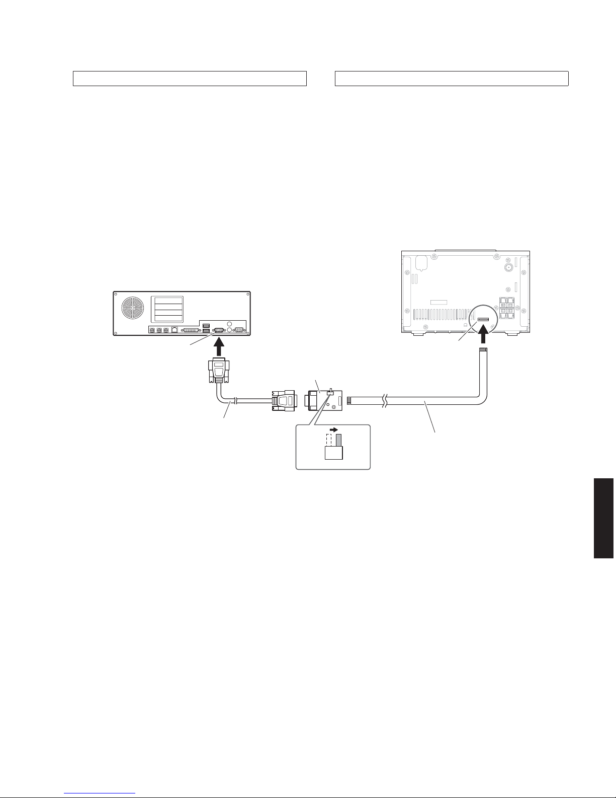
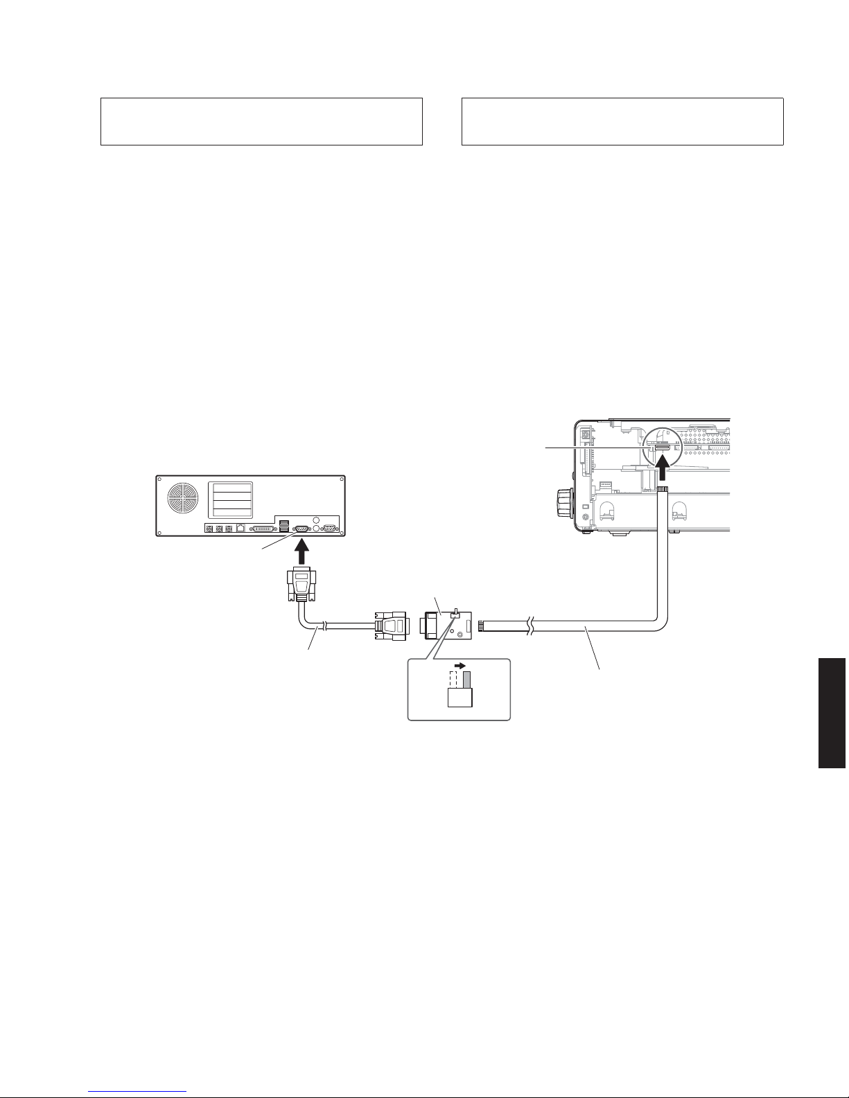
● 接続
※ 本機の電源コードを AC コンセントから抜いてく
ださい。
1. RS232C 変換アダプターのスイッチ(SW7)を
“FLASHUCOM” 側に設定します。(Fig.1)
2. 本機の書き込み用ポート(MAINP.C.B. の CB255)
と PC のシリアルポート(RS232C)を下記のよう
に接続します。(Fig.1)
● Connection
* Disconnect the power cable of this unit from the
AC outlet.
1. Set the switch (SW7) of RS232C conversion
adaptor to the “FLASH UCOM” position. (Fig. 1)
2. Connect the writing port (CB255 of MAIN P.C.B.)
located on the rear panel of this unit to the serial
port (RS232C) of the PC with RS232C cross
cable, RS232C conversion adaptor and flexible
flat cable as shown below. (Fig. 1)
Fig. 1
● 操作方法
1. 本機の電源コードを AC コンセントに接続します。
本機の電源が入り、マイコンが書き込みモードに
なります。
● Operation procedure
1. Connect the power cable of this unit to the AC
outlet.
The power to this unit is turned on and the
microprocessor is in the writing mode.
メインマイコンファームウェアのアップデート
Updating the main microprocessor firmware
26
CRX-040/CRX-140/NS-BP80
CRX-040/CRX-140/
NS-BP80
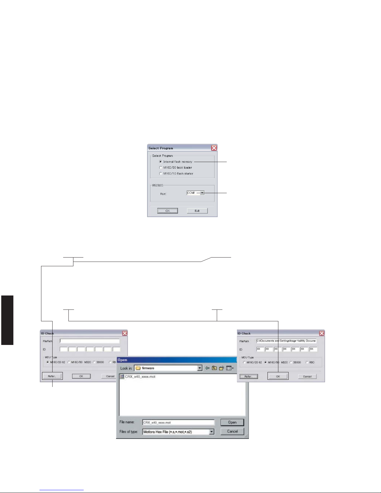
Fig. 2
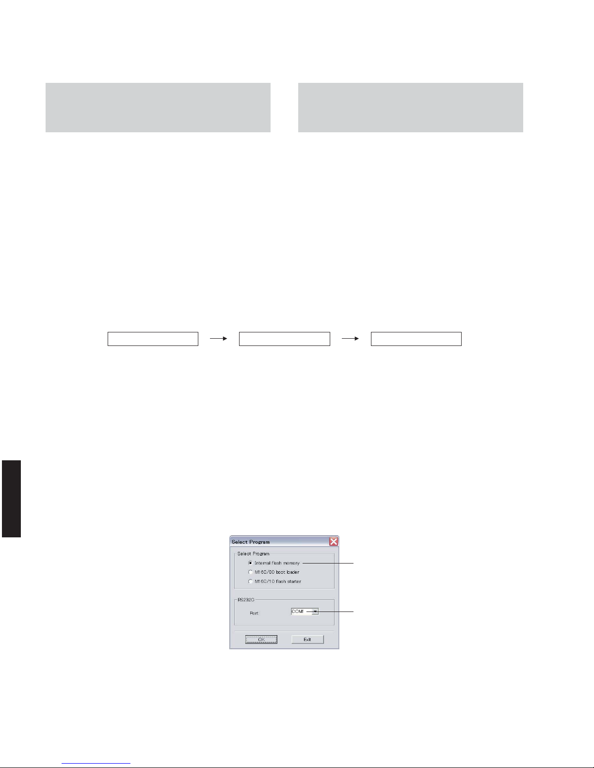
2. FlashSta.exe を起動します。
下記の画面が表示されます。(Fig.2)
3. 送信データ、ポートを選択します。(Fig.2)
・ SelectProgram
Internalflashmemory を選択します。
・ RS232C
接続している RS-232 Cポートを選択します。
※ ポートの選択は COM1 〜 4 までが使用でき
ます。
COM5 以上は使用できませんので、PC 側の
設定で COM1 〜 4 を選択してください。
2. Start up FlashSta.exe.
The screen appears as shown below. (Fig. 2)
3. Select the data to be transmitted and port. (Fig. 2)
• Select Program
Select Internal flash memory.
• RS232C
Select the port of RS-232C
* For selection of the port, COM1 to 4 can be
used.
As COM5 or higher port cannot be used,
select out of COM 1 to 4 of the setting on
the PC side.
Select Internal flash memory
Internalflashmemory を選択します
Select the port of RS-232C
接続している RS-232C ポートを選択します
4.[Refer...]をクリックし、書き込むファームウェア
を選択します。(Fig.3)
メインマイコンファームウェア:
CRXx40xxxx.mot
※ ID、および MCUType は書き込みファイル選
択後、自動的に取り込まれます。(Fig.3)
[OK]をクリックします。(Fig.3)
4. Click [Refer...] and select the firmware name.
(Fig. 3)
Main microprocessor firmware:
CRX_x40_xxxx.mot
* The ID code and MCU type are loaded auto-
matically when the file is selected. (Fig. 3)
Click [OK]. (Fig. 3)
Fig. 3
When [Refer...] is clicked, the
“Open” screen appears.
[Refer...]をクリックすると「ファ
イルを開く」が表示されます
27
CRX-040/CRX-140/NS-BP80
CRX-040/CRX-140/
NS-BP80
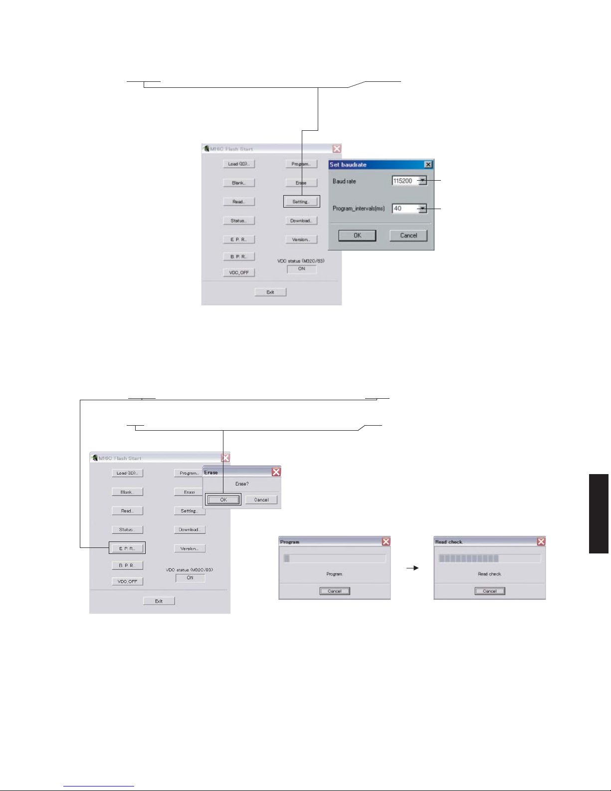
5. Click [Setting], and set the baud rate. (Fig. 4)
* Reduce the baud rate if a transmission error
occurs frequently.
Fig. 4
115200
40
5.[Setting]をクリックし、通信速度の設定を行い
ます。(Fig.4)
※ 送信エラーが多発する場合は、通信速度を下
げてください。
6.[E.P.R]をクリックすると、「Erase」が表示されま
す。(Fig.5)
7.[OK]をクリックし、書き込みを開始します。
(Fig.5)
6. Click [E.P.R.], then the “Erase” screen appears.
(Fig. 5)
7. Click [OK] to start writing. (Fig. 5)
Writing being executed.
書き込み中
Fig. 5
28
CRX-040/CRX-140/NS-BP80
CRX-040/CRX-140/
NS-BP80
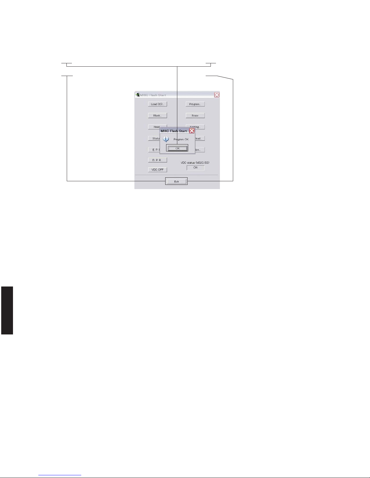
8. ファームウェアの書き込みが完了すると、以下の
画面が表示されます。(Fig.6)
[OK]をクリックします。(Fig.6)
9.[Exit]をクリックして FlashSta.exe を終了します。
(Fig.6)
8. When writing of the firmware is completed, the
screen appears as shown below. (Fig. 6)
Click [OK]. (Fig. 6)
9. Click [Exit] to end FlashSta.exe. (Fig. 6)
Fig. 6
29
CRX-040/CRX-140/NS-BP80
CRX-040/CRX-140/
NS-BP80
Serial port (RS232C)
RS232C cross cable
RS232C クロスケーブル
PC
Flexible flat cable (9P)
カード電線(9P)
RS232C conversion adaptor
RS232C 変換アダプター
SW7
FLASH
UCOM
OTHER
This unit / 本機
Writing port / 書き込みポート
(CONNECTOR P.C.B. CB606)
● 接続
※ 本機の電源コードを AC コンセントから抜いてく
ださい。
・ サイドカバー Rを取り外します。(「分解手順」参照)
・ 本機の書き込み用ポート(CONNECTORP.C.B. の
CB606)と PC のシリアルポート(RS232C)を下
記のように接続します。(Fig.1)
・ RS232C 変換アダプターのスイッチ(SW7)を
“FLASHUCOM” 側に設定します。(Fig.1)
● Connection
* Disconnect the power cable of this unit from the
AC outlet.
• Remove the side cover R. (See “DISASSEMBLY
PROCEDURES”)
• Connect the writing port (CB606 of CONNECTOR
P.C.B.) of this unit to the serial port (RS232C)
of the PC with RS232C cross cable, RS232C
conversion adaptor and flexible flat cable as
shown below. (Fig. 1)
• Set the switch (SW7) of RS232C conversion
adaptor to the “FLASH UCOM” position. (Fig. 1)
Fig. 1
ワイヤレスモジュールファームウエアと
AirWired マイコンファームウエアのアップデート
Updating the Wireless Module Firmware and
the AirWired microprocessor Firmware
30
CRX-040/CRX-140/NS-BP80
CRX-040/CRX-140/
NS-BP80
B-1AWUPGRADE1-1VER:D016 B-2AWUGREADY
Main menu 1 /
メインメニュー 1
Main menu B /
メインメニュー B
Sub-menu B-2 /
サブメニュー B-2
1. 本機の書き込み用ポートにカード電線を接続しま
す。(「接続」参照)
2. 本機の電源コードを AC コンセントに接続します。
3. ダイアグを起動し、サブメニュー “B-2.AW UG
READY” を選択します。(「ダイアグ」参照)
4. FlashSta.exe を起動します。
下記の画面が表示されます。(Fig.2)
5. 送信データ、ポートを選択します。(Fig.2)
・ SelectProgram
Internalflashmemory を選択します。
・ RS232C
接続している RS-232 Cポートを選択します。
※ ポートの選択は COM1 〜 4 までが使用でき
ます。
COM5 以上は使用できませんので、PC 側の
設定で COM1 〜 4 を選択してください。
1. Connect the flexible flat cable to the writing port
of this unit. (See “Connection”)
2. Connect the power cable of this unit to the AC
outlet.
3. Start up the self-diagnostic function and select
“B-2. AW UG READY” sub-menu. (See “SELFDIAGNOSTIC FUNCTION”)
4. Start up FlashSta.exe.
The screen appears as shown below. (Fig. 2)
5. Select the data to be transmitted and port. (Fig. 2)
• Select Program
Select Internal flash memory.
• RS232C
Select the port of RS-232C
* For selection of the port, COM1 to 4 can be
used.
As COM5 or higher port cannot be used,
select out of COM 1 to 4 of the setting on
the PC side.
Fig. 2
Select Internal flash memory
Internalflashmemory を選択します
Select the port of RS-232C
接続している RS-232C ポートを選択します
● 操作方法
注意: 先に「ワイヤレスモジュールファームウェ
アの書き込み」を、次に「AirWired マイ
コンファームウェアの書き込み」を行います。
そうしないと、本機は正常に動作しません。
下記の順番で操作を行ってください。
ワイヤレスモジュールファームウエアの書き込み
ステップ 1 〜 5、6-A、7 〜 13、14-A
AirWired マイコンファームウェアの書き込み
ステップ 1 〜 5、6-B、7 〜 13、14-B
● Operation procedure
CAUTION: Perform “Writing the wireless module
firmware” 1st and “Writing the AirWired
Microprocessor Firmware” 2nd, otherwise
this unit will not operate properly.
Perform the following procedures.
Writing the wireless module firmware
Step 1 to 5, 6-A, 7 to 13, 14-A
Writing the AirWired microprocessor firmware
Step 1 to 5, 6-B, 7 to 13, 14-B
 Loading...