

Yamaha M2500 User Guide

MIXING CONSOLE
Owner’s Manual
Mode d’emploi
Bedienungsanleitung
M

FCC INFORMATION (U.S.A.)
1. IMPORTANT NOTICE: DO NOT MODIFY THIS UNIT! This product, when installed as indicated in the instructions contained in this manual, meets FCC
requirements. Modifications not expressly approved by Yamaha may void your authority, granted by the FCC, to use the product.
2. IMPORTANT: When connecting this product to accessories and/or another product use only high quality shielded cables. Cable/s supplied with this product MUST
be used. Follow all installation instructions. Failure to follow instructions could void your FCC authorization to use this product in the USA.
3. NOTE: This product has been tested and found to comply with the requirements listed in FCC Regulations, Part 15 for Class “B” digital devices. Compliance with
these requirements provides a reasonable level of assurance that your use of this product in a residential environment will not result in harmful interference with
other electronic devices. This equipment generates/uses radio frequencies and, if not installed and used according to the instructions found in the users manual, may
cause interference harmful to the operation of other electronic devices. Compliance with FCC regulations does not guarantee that interference will not occur in all
installations. If this product is found to be the source of interference, which can be determined by turning the unit “OFF” and “ON”, please try to eliminate the
problem by using one of the following measures: Relocate either this product or the device that is being affected by the interference. Utilize power outlets that are on
different branch (circuit breaker or fuse) circuits or install AC line filter/s. In the case of radio or TV interference, relocate/reorient the antenna. If the antenna lead-in
is 300 ohm ribbon lead, change the lead-in to coaxial type cable. If these corrective measures do not produce satisfactory results, please contact the local retailer
authorized to distribute this type of product. If you can not locate the appropriate retailer, please contact Yamaha Corporation of America, Electronic Service
Division, 6600 Orangethorpe Ave, Buena Park, CA 90620
The above statements apply ONLY to those products distributed by Yamaha Corporation of America or its subsidiaries.
ADVARSEL!
Lithiumbatteri—Eksplosionsfare ved fejlagtig
håndtering. Udskiftning må kun ske med batteri
af samme fabrikat og type. Levér det brugte
batteri tilbage til leverandoren.
VARNING
Explosionsfara vid felaktigt batteribyte. Använd
samma batterityp eller en ekvivalent typ som
rekommenderas av apparattillverkaren.
Kassera använt batteri enligt fabrikantens
instruktion.
VAROITUS
Paristo voi räjähtää, jos se on virheellisesti
asennettu. Vaihda paristo ainoastaan
laitevalmistajan suosittelemaan tyyppiin. Hävitä
käytetty paristo valmistajan ohjeiden
mukaisesti.
NEDERLAND THE NETHERLANDS
● Dit apparaat bevat een lithium batterij voor geheugen
back-up.
● Raadpleeg uw leverancier over de verwijdering van de
batterij op het moment dat u het apparaat ann het einde
van de levensduur afdankt of de volgende Yamaha Service
Afdeiing:
Yamaha Music Nederland Service Afdeiing
Kanaalweg 18-G, 3526 KL UTRECHT
Tel. 030-2828425
● Gooi de batterij niet weg, maar lever hem in als KCA.
● This apparatus contains a lithium battery for memory
back-up.
● For the removal of the battery at the moment of the
disposal at the end of the service life please consult your
retailer or Yamaha Service Center as follows:
Yamaha Music Nederland Service Center
Address: Kanaalweg 18-G, 3526 KL
UTRECHT
Tel: 030-2828425
● Do not throw away the battery. Instead, hand it in as small
chemical waste.

Important Information
Read the Following Before Operating M2500
Warnings
• Do not allow water to enter this unit or allow the
unit to become wet. Fire or electrical shock may
result.
• Connect this unit’s power cord only to the
power supply unit, and connect the power supply unit to an AC outlet of the type stated in this
Owner’s Manual or as marked on the power
supply unit. Failure to do so is a fire and electrical shock hazard.
• Do not scratch, bend, twist, pull, or heat the
power cord. A damaged power cord is a fire and
electrical shock hazard.
• Do not place heavy objects, including this unit,
on top of the power cord. A damaged power
cord is a fire and electrical shock hazard. In particular, be careful not to place heavy objects on a
power cord covered by a carpet.
• If you notice any abnormality, such as smoke,
odor, or noise, or if a foreign object or liquid
gets inside the unit, turn it off immediately.
Remove the power cord from the AC outlet.
Consult your dealer for repair. Using the unit in
this condition is a fire and electrical shock hazard.
• Should this power supply be dropped or the
cabinet be damaged, turn the power switch off,
remove the power plug from the AC outlet, and
contact your dealer. If you continue using the
unit without heeding this instruction, fire or
electrical shock may result.
• If the power cord is damaged (i.e., cut or a bare
wire is exposed), ask your dealer for a replacement. Using the unit with a damaged power
cord is a fire and electrical shock hazard.
• Do not modify the unit. Doing so is a fire and
electrical shock hazard.
Cautions
• This unit is heavy. Use two or more people to
carry it.
• Hold the power cord plug when disconnecting it
from an AC outlet. Never pull the cord. A damaged power cord is a potential fire and electrical
shock hazard.
• Do not touch the power plug with wet hands.
Doing so is a potential electrical shock hazard.
• Use only the included power supply for this unit.
Using other types may be a fire hazard.
Operating Notes
• The digital circuits of this unit may induce a
slight noise into nearby radios and TVs. If noise
occurs, relocate the affected equipment.
• Using a mobile telephone near this unit may
induce noise. If noise occurs, use the telephone
away from the unit.
• XLR-type connectors are wired as follows:
pin 1: ground, pin 2: hot (+), and pin 3: cold (–).
• Insert TRS phone jacks are wired as follows:
sleeve: ground, tip: send, and ring: return.
• The performance of components with moving
contacts, such switches, rotary controls, faders,
and connectors, deteriorates over time. The rate
of deterioration depends on the operating environment and is unavoidable. Consult your
dealer about replacing defective components.
Keep This Manual For Future Reference.
M2500—Owner’s Manual
iii

Introduction
Thank you for purchasing the Yamaha M2500 mixing console. The M2500 is a highly costeffective mixing console that features functionality such as scene memory, PAN control
that is switchable between LR/LCR, and GROUP/AUX FADER FLIP switches. In order to
take full advantage of the M2500’s functionality and ensure trouble-free use, please read
this manual carefully.
Note:
• This manual assumes that you have an understanding of basic mixing console opera-
• The M2500 series includes five models: M2500-24, M2500-32, M2500-40C, M2500-
Contents
tion and terminology.
48C, and M2500-56C. This manual bases its explanation on the M2500-24. Differences
in the specifications of each models are given in curly brackets { }.
Features of the system............................. 2
Control panel..........................................3
Input channel section .........................................3
GROUP/AUX master section............................. 9
GROUP/AUX FLIP switch............................... 14
Stereo/monaural master section ......................16
Matrix section ...................................................18
Monitor section ................................................19
Talkback/oscillator section............................... 21
Meter select section...........................................22
Control section .................................................22
Meter bridge...................................................... 24
Rear panel.............................................25
Monaural input channel input/output jacks... 25
Stereo input channel input/output jacks.........26
Master section input/output jacks ................... 27
The Scene Memory function .................30
What is scene memory?.................................... 30
Modes of the scene memory function .............30
Operation in Normal mode .............................31
Check mode operation .....................................32
Utility mode procedures...................................34
Control change table ........................................36
Mute groups......................................................37
About the local control circuit......................... 38
Error messages...................................... 39
Specifications........................................ 40
General specifications ...................................... 40
Input/output characteristics ............................ 41
Other................................................................. 42
Dimensions........................................... 43
MIDI data format .................................. 44
MIDI Implementation Chart.................. 45
M2500—Owner’s Manual
1

Features of the system
• The M2500-24 {32/40C/48C/56C} provides 24
{32/40/48/56} monaural input modules and
four stereo input modules. It also provides 14
AUX outputs, eight group outputs, stereo output, and monaural output, for a generous total
of 25 output buses. The M2500 is ideal for a
wide range of applications from use as a main
PA mixer to use in installed systems.
• Eight independent matrix outputs are provided.
The GRP/AUX, STEREO, and MONO/C channel output signals and the input signals from
dedicated inputs can be mixed freely, and output
from the eight MATRIX OUT jacks. This is convenient for foldback, or for creating individual
mixes for monitor speakers or amps.
• Monaural input channels and GRP/AUX output
channels allow you to select not only conventional LR (stereo) output or monaural output,
but also LCR (stereo+center) output. When LCR
output is selected, the level of the center output
signal is also controlled by the PAN control, for
accurate spatial positioning when a three-channel stereo+center playback system is used.
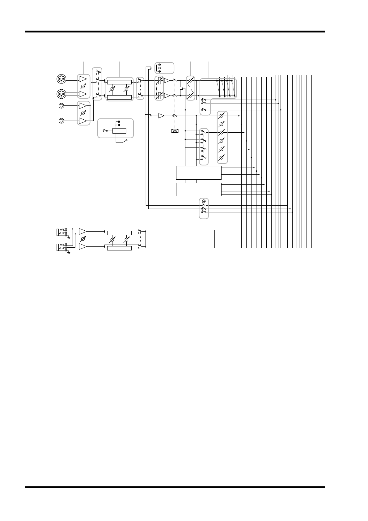
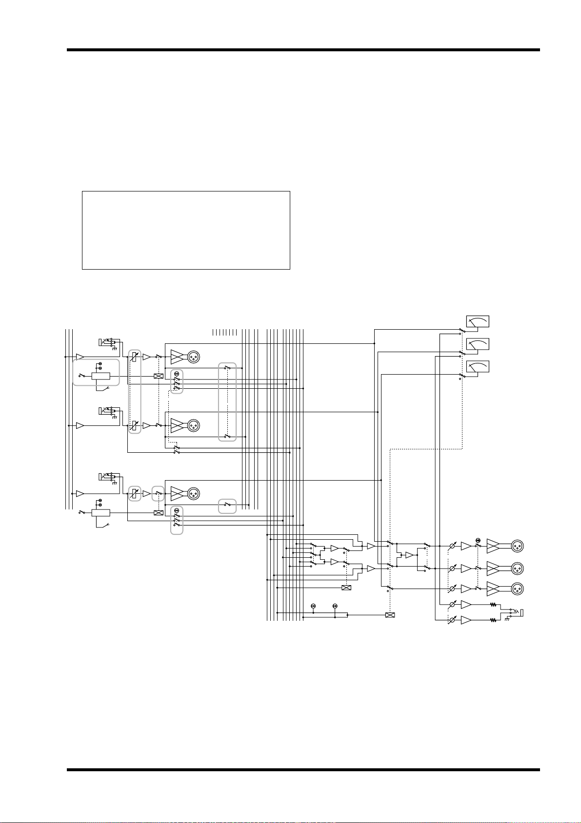
• Monaural input channels provide a 26 dB pad,
high pass filter switch, phase switch, four-band
EQ, and 100 mm full-stroke faders. +48 V phantom power that can be switched on/off individually for each channel is also provided.
• An INSERT I/O jack is provided on each monaural input channel as well as on the AUX 1–6,
GRP/AUX, STEREO, and MONO/C output
channels. This allows you to insert external
effect units as necessary.
• The Scene Memory function allows you to store
the on/off status of each mono/stereo input
channel and GRP/AUX 1–8, STEREO, and
MONO/C output channels as one of 128 scenes.
Scenes can be recalled at any time from the front
panel or via MIDI. In addition, control change
messages can be used to individually switch
these channels on/off from an external device.
• Eight DIRECT RECALL switches are provided
to allow scene memories 1–8 to be recalled at the
touch of a single button. This allows multiple
channels to be switched on/off quickly.
• By changing a setting, the DIRECT RECALL
switches can be used as mute group switches.
Mute group switch settings allow the DIRECT
RECALL switches to individually add/remove
eight sets of mute settings.
• PFL switches are provided on all input channels,
and AFL switches are provided on all master
outputs. In addition, a MASTER PFL switch
allows the master output monitor signal to be
switched between pre/post fader. You can rapidly check the input/output signal sources at a
variety of points.
• The talkback signal and the test tone oscillator
(PINK/10 kHz/1 kHz/100 Hz) can be sent to any
of the AUX 1-2, 2-6, 7-10, 11-14, STEREO, or
MONO/C buses.
• The GROUP/AUX FLIP switch allows the eight
100 mm fader output channels to be used either
for the GROUP or AUX buses. When used for
the AUX buses, all 14 AUX buses can be controlled by 100 mm faders, which is convenient
when using the M2500 as a stage monitor console.
2
M2500—Owner’s Manual
EQ
EQ
Control panel
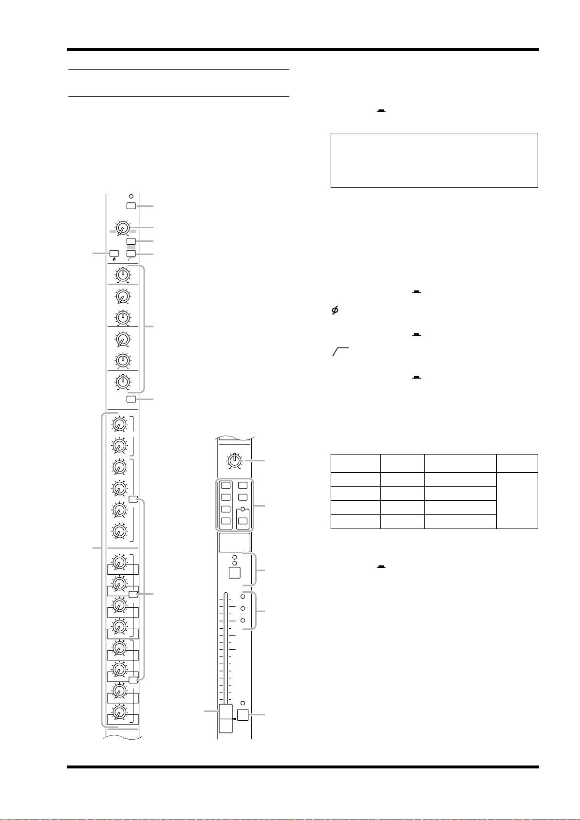
Input channel section
Monaural input channels
A
+48 V (phantom power) switch
This switches the +48 V phantom power supply on/
off for the corresponding channel. When the switch is
pressed in ( ), phantom power is on. At this time
the indicator above the switch will light.
The M2500-24 {32/40C/48C/56C} provides 24 {32/
40/48/56} input channels. The specifications of each
input channel are the same for all models of the
series.
1
+48V
GAIN
4
8
+10
–16 –60
HI
–15 +15
HI-MID
400 8k
–15 +15
LO-MID
80 1.6k
–15 +15
LO
–15 +15
010
AUX1 PRE
010
AUX2
010
AUX3
010
AUX4
010
AUX5
010
AUX6
010
AUX7
010
AUX8
010
AUX9
010
AUX10
010
AUX11
010
AUX12
010
AUX13
010
AUX14
PAN
C
26dB
2
–34
3
5
80
6
7
EQ
010
AUX14
PAN
ST
MONO
LCR
CHECK
ON
J
K
PRE
LCR
ODD EVEN
1-2
3-4
5-6
7-8
L
ON/EDIT
PRE
PRE
9
N
10
PEAK
5
SIGNAL
0
5
10
20
30
40
50
60
NOM
PFL
M
O
Note: If you wish to use phantom power, make
sure that the rear panel PHANTOM MASTER
switch (page 29) is turned on. (The PHANTOM
MASTER indicator on the meter bridge will light.)
B
GAIN control
This adjusts the input sensitivity. This control has a
range of –16 dB to –60 dB when the 26 dB pad switch
( 3 ) is off, and a range of +10 dB to –34 dB when the
pad is on.
C
26 dB pad switch
This attenuates the input signal by 26 dB. When the
switch is pressed in ( ), the pad is on.
D
(phase) switch
This reverses the phase of the input signal. When the
switch is pressed in ( ), the phase is reversed.
E
(high pass filter) switch
80
This switches the high pass filter on/off. When the
switch is pressed in ( ), the high pass filter is on,
and the frequency range below 80 Hz will be attenuated by an 18 dB/oct curve.
F
controls
This is a four-band equalizer. The type, center frequency, and gain range of each band is shown below.
Band Type Center frequency Gain
HIGH Shelving 10 kHz
HIGH-MID Peaking 400 Hz to 8 kHz
LOW-MID Peaking 80 Hz to 1.6 kHz
LOW Shelving 100 Hz
G
switch
This switches the equalizer on/off. When the switch is
pressed in ( ), the equalizer will be on.
H
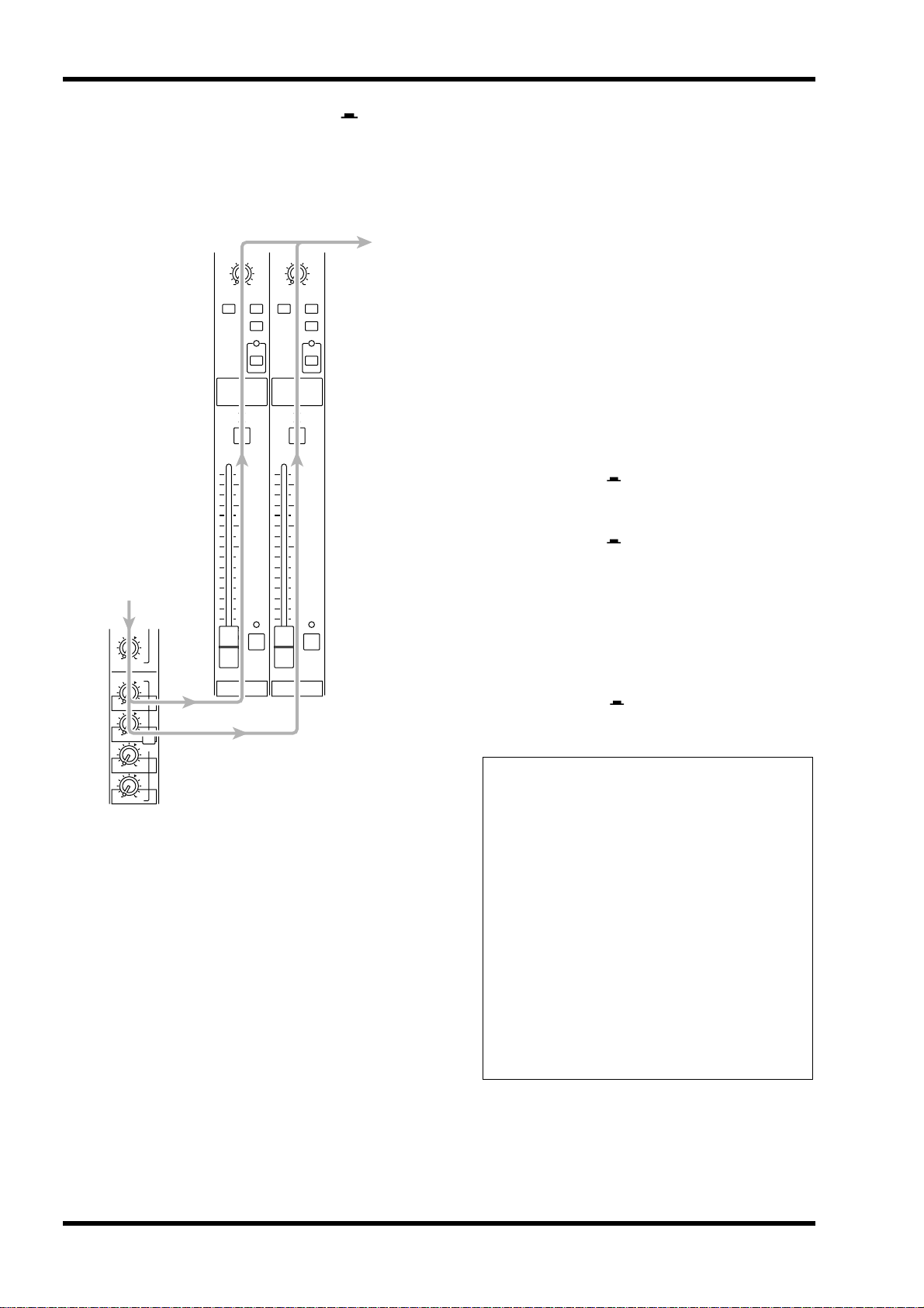
AUX 1 – AUX 14 controls
These adjust the level at which the signal of the monaural input channel is set to AUX buses 1 to 14. Nominal level (0 dB) is when the control is at the “
position. The pre-fader signal will be sent to AUX
buses 1/2. For AUX buses 3 to 14, you can use the
PRE switch ( 9 ) to switch between pre/post fader.
±15 dB
▲
”
M2500—Owner’s Manual
3
Control panel
I
PRE switches
If these switches are turned on ( ), the post-EQ prefader signal will be sent to the corresponding AUX
buses. If these switches are turned off ( ), the postfader signal will be sent. Switches are provided to
independently switch three groups of AUX buses: 3–
6, 7–10, and 11–14.
J
PAN control
This adjusts the pan or balance of the signal that is
sent from the monaural input channel to the STEREO, MONO/C, or GROUP buses. The function of
the PAN control will change as follows, depending on
the setting of the channel assign switch ( K ).
●
●
●
•
• ST
•
•
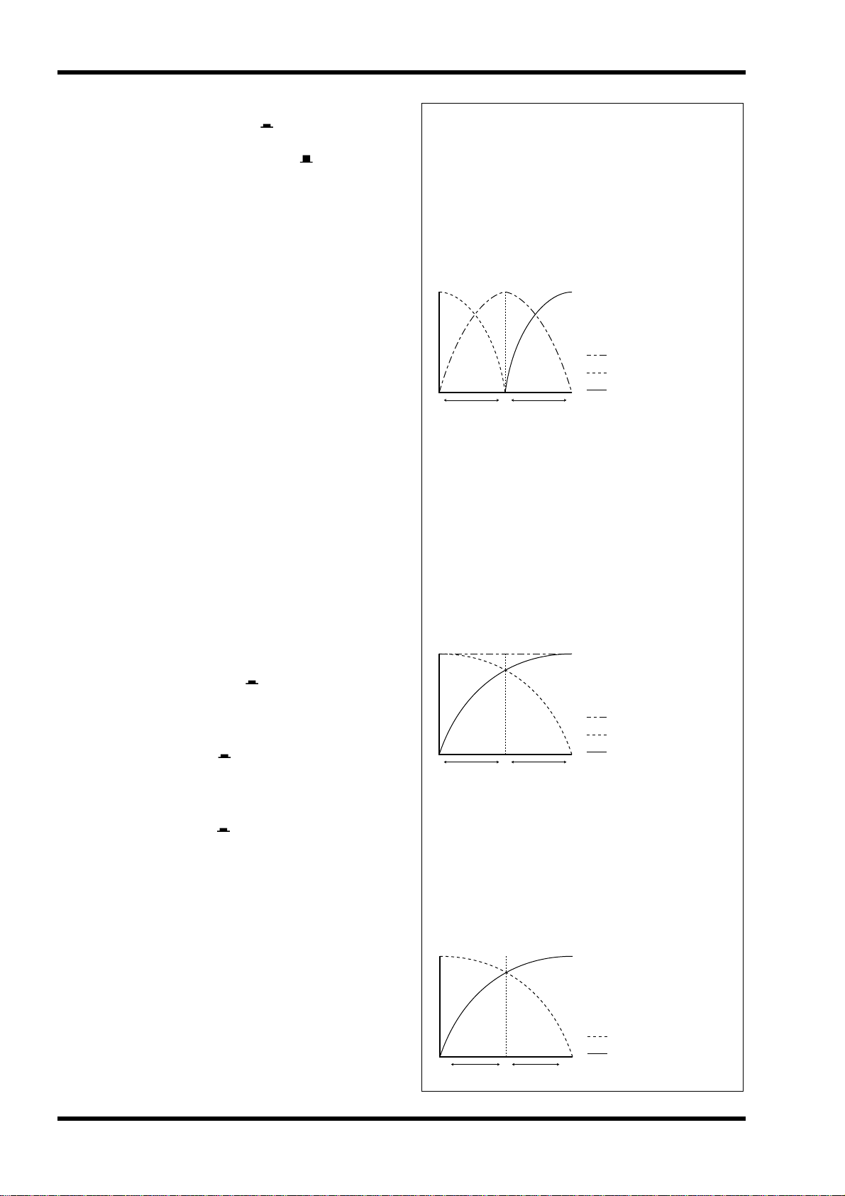
Note:
• The LCR switch takes priority over the ST/MONO
switch. When the LCR switch is on , the post-PAN
signal of the monaural input channel will be sent to
the STEREO bus (L/R) and the MONO/C bus regardless of the on/off status of the ST/MONO switch.
When the LCR switch is on, the level of the signals
that are sent to the STEREO bus (L/R) and MONO/C
bus will change in response to movement of the PAN
control as shown in the following diagram.
< Response curve 1 >
LCR switch= on
When the ST switch is on
PAN will adjust the pan of the signal that is sent from
the monaural input channel to the STEREO L/R bus.
When the LCR switch is on
PAN will adjust the pan of the signal that is sent from
the monaural input channel to the STEREO L/R bus
and MONO/C bus.
When a 1-2/3-4/5-6/7-8 switch is on
PAN will adjust the balance of the signal that is sent
from the monaural input channel to the odd-numbered (1/3/5/7) and even-numbered (2/4/6/8) channels of the corresponding GROUP bus (1-2/3-4/5-6/
7-8).
K
Channel assign switches
These switches assign the post-fader post-PAN signal
to the desired bus.
1-2 / 3-4 / 5-6 / 7-8 switches
When these switches are on ( ), the signal of the
monaural input channel will be sent to the corresponding GROUP bus (1-2/3-4/5-6/7-8).
(stereo) switch
When this switch is on ( ), the post-PAN signal of
the monaural input channel will be sent to the STEREO bus.
MONO (monaural) switch
When this switch is on ( ), the signal of the monaural input channel will be sent to the MONO/C bus.
LCR switch
When this switch is on, the indicator above the switch
will light, and the post-PAN signal of the monaural
input channel will be sent to the STEREO bus and the
MONO/C bus.
Signal level
CRL
PAN control
Signal sent to the MONO/C bus
Signal sent to STEREO bus L
Signal sent to STEREO bus R
• When the LCR switch is off , the ST/MONO switch
will function as a conventional channel assign
switch. If ST is on , the post-PAN signal of the
monaural input channel will be sent to the ST bus.
If the MONO switch is on , the signal of the monaural input channel will be sent directly to the
MONO/C bus. (The signal sent to the MONO/C
bus will not be affected by the PAN control.) If the
LCR switch is off and the ST/MONO switch is on,
movements of the PAN control will affect the signal levels sent to the STEREO bus (L/R) and
MONO/C bus as shown in the following diagram.
< Response curve 2 >
LCR switch= off
ST switch= on
MONO switch= on
Signal level
CRL
PAN control
Signal sent to the MONO/C bus
Signal sent to STEREO bus L
Signal sent to STEREO bus R
• The 1-2/3-4/5-6/7-8 switches can always be used,
regardless of the on/off status of the LCR switch.
When the 1-2/3-4/5-6/7-8 switches are on , the
post-PAN signal of the monaural input channel
will be sent to the corresponding GROUP bus 1–8.
When the 1-2/3-4/5-6/7-8 switches are on, movements of the PAN control will affect the signal levels sent to GROUP buses 1–8 as shown in the
following diagram.
4
M2500—Owner’s Manual
Signal level
C EVENODD
PAN control
< Response curve 3 >
1-2/3-4/5-6/7-8 switches= on
Signal sent to GROUP buses 1/3/5/7
Signal sent to GROUP buses 2/4/6/8
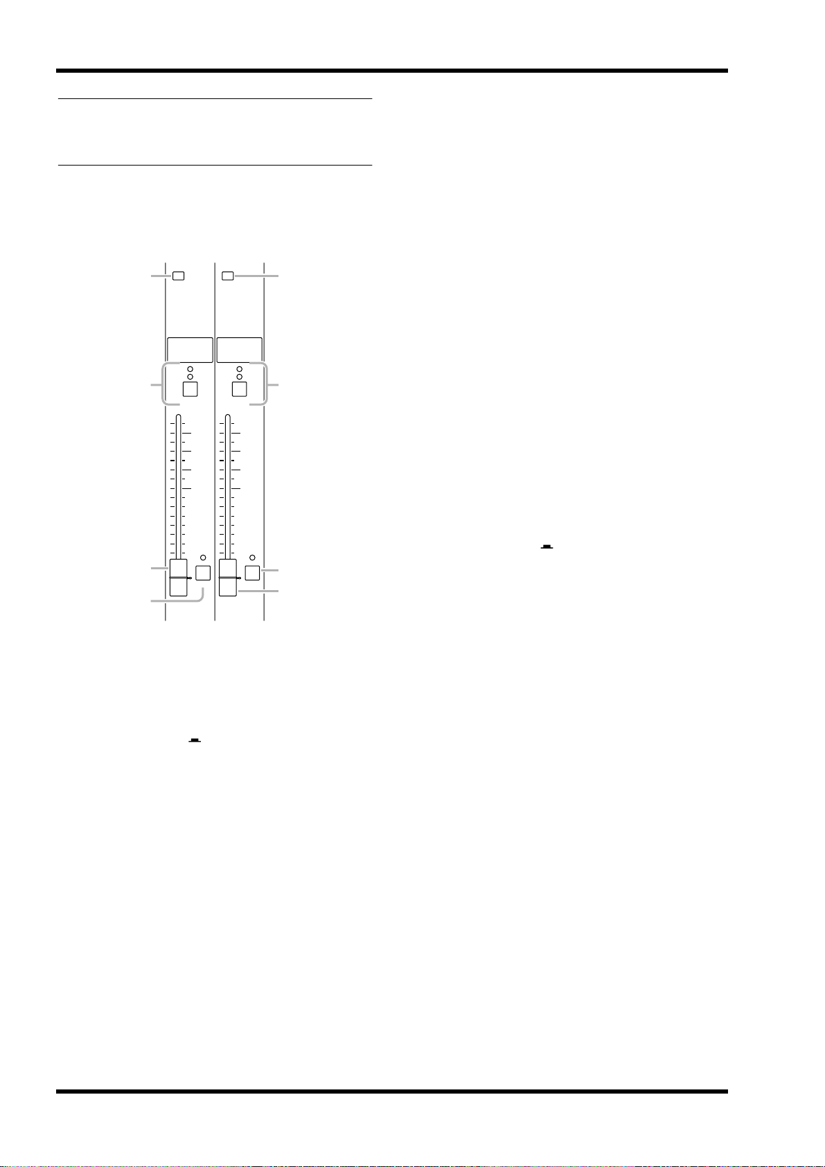
L
ON/EDIT switch / ON , CHECK indicators
The function of this switch and these indicators will
change depending on the mode of the M2500.
In normal mode
You can use the ON/EDIT switch to turn the monaural input channel on/off. When the channel is
switched on/off, the ON indicator will be lit/dark to
indicate the status. Channels that are switched off will
not send any signals to the GROUP, STEREO,
MONO/C, or AUX buses, but you can still use the
PFL switch ( O ) to monitor the signal from the
MONITOR OUT jacks or the PHONES jack.
In check mode
When a scene (which contains the on/off state of the
ON/EDIT switches) is selected, the on/off status
memorized in that scene will be indicated by the lit/
dark status of the CHECK indicator. In check mode,
you can also use the ON/EDIT switch to switch the
CHECK indicator between lit/dark. (The current on/
off setting will not be affected.) For details on check
mode, refer to page 32.
●
Control panel
M
PEAK / NOM / SIGNAL indicators
These three indicators allow you to check the prefader signal level of the monaural input channel.
PEAK indicator
This will light when the signal exceeds nominal level
by 17 dB.
NOM (nominal) indicator
This will light when the signal reaches nominal level
(0 dB).
SIGNAL indicator
This will light when the signal reaches a level 13 dB
below nominal.
N
Channel fader
This adjusts the output level of the monaural input
channel signal. This fader affects the level of the signal that is sent to the GROUP, STEREO, MONO/C,
and AUX (if the PRE switch is off) buses.
O PFL (pre-fader listen) switch
When this switch is on ( ), the pre-fader signal will
be sent to the MONITOR INPUT PFL bus, and can
be monitored from the MONITOR OUT and
PHONES jacks.
●
•
•
•
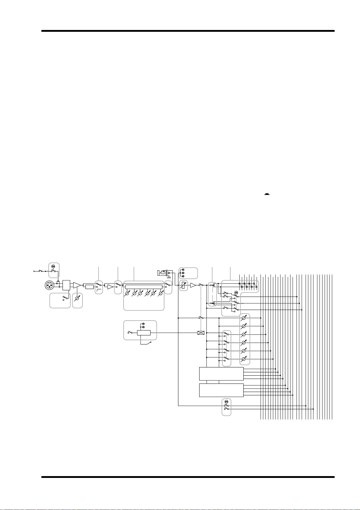
PHANTOM
MASTER
INPUT
1-24
1-32
1-40
1-48
1-56
1
+48V
(–26dB)
(0dB)
26dB
PAD
GAIN
23
5 4
HPF
80
6 J KM
INSERT I/O
0dB
LO
ON/EDIT
4 stage EQ
g
f
LO-MID
Control
f
CHECK
ON
from CPU
g
HI-MID
Ø
L
MONITOR
INPUT
MASTER
PFL AFL
(PFL)
ST
ST
PEAK
NOM
SIGNAL
EQ
HI
7
N
PAN
ST
MONO
PRE
AUX 7-10
Same as AUX 3-6
AUX 11-14
Same as AUX 3-6
PFL
LCR
AUX1
AUX2
AUX3
AUX4
AUX5
AUX6
9O8
AUXGROUP
11
9
23456788765432
1413121110
STEREO
LR
MONO
MONO/C
LR
ST
MONO
MONO
ON
ON
LR
RL
M2500—Owner’s Manual
5
Control panel
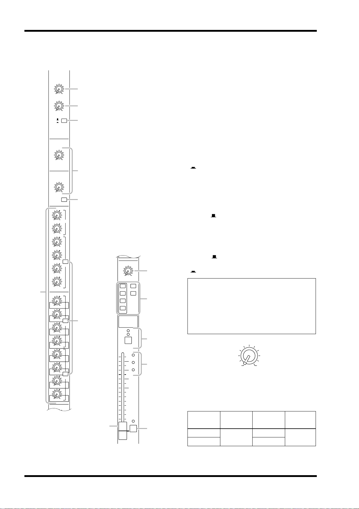
Stereo input channels
GAIN
A
EQ
PRE
PRE
PRE
1
2
3
4
5
7
L
6
+10 –30
B
+10 –20
A
B
HI
–15 +15
LO
–15 +15
010
AUX1 PRE
010
AUX2
010
AUX3
010
AUX4
010
AUX5
010
AUX6
010
AUX7
010
AUX8
010
AUX9
010
AUX10
010
AUX11
010
AUX12
010
AUX13
010
AUX14
BAL
LCR
ODD EVEN
010
AUX14
BAL
LR
ODD EVEN
1-2
MONO
3-4
5-6
7-8
ON/EDIT
10
5
SIGNAL
0
5
10
20
30
40
50
60
ST
CHECK
ON
PEAK
NOM
PFL
8
9
J
K
M
The M2500 provides four stereo input channels,
allowing line-level stereo sources such as sub-mixers,
effect processors, and CD players to be input. Of the
stereo input channels 1–4, channel 1 provides both
XLR and RCA phono input jacks, and you can select
and use one of these. Channels 2–4 provide a pair of
TRS phone input jacks. For this reason, there are
slight differences between the controllers of channel 1
and channels 2–4. Our explanation here will be based
on stereo input channel 1, and any differences for stereo input channels 2–4 will be explained later.
A GAIN A control
This adjusts the input sensitivity of the signal that is
input from the XLR connectors of the ST CH 1
INPUT A jacks (page 26). Levels of +10 dB to –30 dB
are supported. If the A/B select switch (3) is in the B
( ) position, this control will have no effect.
B GAIN B control
This adjusts the input sensitivity of the signal that is
input from the RCA phono connectors of the ST CH
1 INPUT B jacks (page 26). Levels of +10 dB to
–20 dB are supported. If the A/B select switch (3) is
in the A ( ) position, this control will have no
effect.
C A/B switch
This selects the input jacks that will be used for stereo
input channel 1. When the switch is in the upward
position ( ), the ST CH 1 INPUT A jacks can be
used. When the switch is in the downward position
( ), the ST CH 1 INPUT B jacks can be used.
Note: Since stereo input channels 2–4 have only
one set of inputs, only one GAIN control is provided. (Nor is there an A/B select switch.) This
control will adjust the input sensitivity of the signal that is input from the TRS phone connectors
for the ST CH 2–4 INPUT jacks (page 26). Levels
of +10 dB to –30 dB are supported.
GAIN
+10 –30
D EQ controls
This is a two-band equalizer. The equalizer type, center frequency, and gain range of each band is shown
below.
Band Type
HIGH
LOW 100 Hz
Shelving
Center
frequency
10 kHz
±15 dB
Gain
6 M2500—Owner’s Manual

Control panel
E EQ switch
This turns the equalizer on/off. When the switch is
pressed in ( ), the equalizer is on.
F AUX 1–AUX 14 controls
These adjust the level at which the signal of the stereo
input channel (the L/R input signals mixed to a monaural signal) is sent to the AUX buses 1–14. Placing
the control at the “▲” position will produce nominal
level (0 dB). For AUX buses 1/2, the pre-fader signal
will be output. For AUX buses 3–14, the PRE switch
(7) can be used to switch the signal pre or post
fader.
G PRE switches
If these switches are turned on ( ), the pre-fader
signal will be sent to the corresponding AUX buses. If
these switches are turned off ( ), the post-fader signal will be sent. Switches are provided to independently switch three groups of AUX buses: 3–6, 7–10,
and 11–14.
H BAL control
This adjusts the level balance of the signal that is sent
to the STEREO or GROUP buses.
● If the ST switch is on
The BAL control will adjust the L/R balance at which
the signal of the stereo input channel is sent to the
STEREO bus.
● If a 1-2/3-4/5-6/7-8 switch is on
The BAL control will adjust the balance of the stereo
input channel that is sent to the odd-numbered
channels (1/3/5/7) and even-numbered channels (2/
4/6/8) of the corresponding GROUP bus (1-2/3-4/56/7-8). The L ch of the input signal will be sent to the
odd-numbered channel of the group bus, and the R
channel of the input signal will be sent to the evennumbered channel of the group bus.
I Channel assign switches
These switches assign the signal that has passed
through the fader and BAL control to the desired
bus(es). Any or all of the channel assign switches can
be used simultaneously.
• 1-2/3-4/5-6/7-8 switches
When these switches are on ( ), the signal of the
stereo input channel will be sent to the corresponding GROUP bus (1-2/3-4/5-6/7-8).
• ST (stereo) switch
When this switch is on ( ), the signal of the stereo
input channel will be sent to the STEREO bus.
• MONO (monaural) switch
When this switch is on ( ), the L and R channels of
the input signal will be mixed to monaural, and sent
to the MONO/C bus. The signal that is sent to the
MONO/C bus is not affected by the BAL control.
J ON/EDIT switch / ON, CHECK indicators
The function of this switch and these indicators will
change depending on the mode of the M2500.
● In normal mode
You can use the ON/EDIT switch to turn the stereo
input channel on/off. When the channel is switched
on/off, the ON indicator will be lit/dark to indicate
the status. Channels that are switched off will not
send any signals to the GROUP, STEREO. MONO/C,
or AUX buses, but you can still use the PFL switch
(M) to monitor the signal from the MONITOR OUT
jacks or the PHONES jack.
● In check mode
When a scene is selected, the on/off status memorized
in that scene will be indicated by the lit/dark status of
the CHECK indicator. In check mode, you can also
use the ON/EDIT switch to switch the CHECK indicator between lit/dark. For details on check mode,
refer to page 32.
K PEAK/NOM/SIGNAL indicators
These three indicators allow you to check the prefader signal level of the stereo input channel.
• PEAK indicator
This will light when the signal mixed to monaural
exceeds nominal level by 17 dB.
• NOM (nominal) indicator
This will light when the signal mixed to monaural
reaches nominal level (0 dB).
• SIGNAL indicator
This will light when the signal mixed to monaural
reaches a level 13 dB below nominal.
L Channel fader
This adjusts the output level of the stereo input channel signal. This fader affects the level of the signal that
is sent to the GROUP, STEREO, MONO/C, and AUX
(if the PRE switch is off) buses.
M PFL (pre-fader listen) switch
When this switch is on ( ), the pre-fader signal will
be sent to the MONITOR INPUT PFL bus, and can
be monitored from the MONITOR OUT and
PHONES jacks.
M2500—Owner’s Manual 7
Control panel
INPUT A
ST CH 1
INPUT B
L/MONO
ST CH 2-4
INPUT
LR
INPUT
(PFL)
STEREO
MONO/C
MONO
LR
MONITOR
PFL AFL
ST
ON
MASTER
ST
MONO
RL
ST
MONO
LR
ON
1 4 5 8 9K
3
A
2
B
2 stage EQ
CHECK
ON
from CPU
EQ
HI
LO
2 stage EQ
GAIN B GAIN A
Control
ON/EDIT
L
R
L
R
J
2 stage EQ
R
GAIN
LO
2 stage EQ
EQ
HI
L
PEAK
NOM
SIGNAL
Same as ST CH 1
ST CH 2-4
BAL
ST
MONO
PRE
AUX 7-10
Same as AUX 3-6
AUX 11-14
Same as AUX 3-6
PFL
GROUP
1
AUX1
AUX2
AUX3
AUX4
AUX5
AUX6
7M6
1
8765432
AUX
2345678
9
1413121110
8 M2500—Owner’s Manual
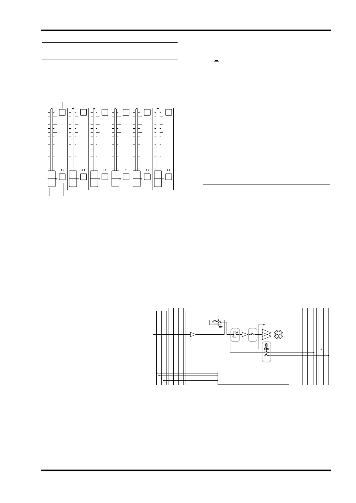
GROUP/AUX master section
AUX 1–6 section
Control panel
A ON switches
These turn AUX OUT 1–6 on/off. When a switch is
on ( ), the signal of the corresponding AUX bus
will be output to the AUX OUT jack.
B AUX 1–6 master faders
These adjust the output levels of AUX OUT 1–6.
1
10
5
0
5
10
20
30
40
50
60
AUX1
10
ON
5
0
5
10
20
30
40
50
60
AFL
AUX2
10
ON
5
0
5
10
20
30
40
50
60
AFL
AUX3
10
ON
5
0
5
10
20
30
40
50
60
AFL
AUX4
10
ON
5
0
5
10
20
30
40
50
60
AFL
AUX5
10
ON
5
0
5
10
20
30
40
50
60
AFL
AUX6
23
These are the output channels that control the signals
of AUX buses 1–6. The signals that have passed
through these output channels will be output individually from the AUX OUT 1–6 jacks (page 27). In
addition, they pass through the MONITOR MASTER
PFL/AFL buses and can be monitored from the
MONITOR OUT L/R and the PHONES jacks.
C AFL (after fader listen) switches
These switches are used to monitor the signal of the
ON
AFL
AUX OUT 1–6 section from the MONITOR OUT/
PHONES jacks. When an AFL switch is on (the
switch above the indicator will light), the pre/afterfader signals of the AUX 1–6 section will be sent to
the MONITOR MASTER PFL/AFL buses respectively, and can be monitored via the MONITOR
OUT/PHONES jacks. At this time, you can use the
MASTER PFL switch (page 19) in the monitor section to select whether you will monitor the pre- or
after-fader signal.
Note: If the PFL switch of even one input channel
is turned on, the signal of the MONITOR INPUT
bus will take priority for monitoring. In this case,
be aware that even if the AFL switch is turned on,
the MONITOR MASTER bus cannot be monitored.
1
2345678
AUX
MONITOR
INPUT
MASTER
PFL AFL
(PFL)
ST
ST
ST
MONO
MONO
ON
MONO
9
1413121110
INSERT I/O
0dB
AUX 1
2 1
to METER
AUX OUT
+4dB
ON
AFL
1
LR
ON
LR
RL
3
AUX 2-6
Same as AUX 1
M2500—Owner’s Manual 9
Control panel
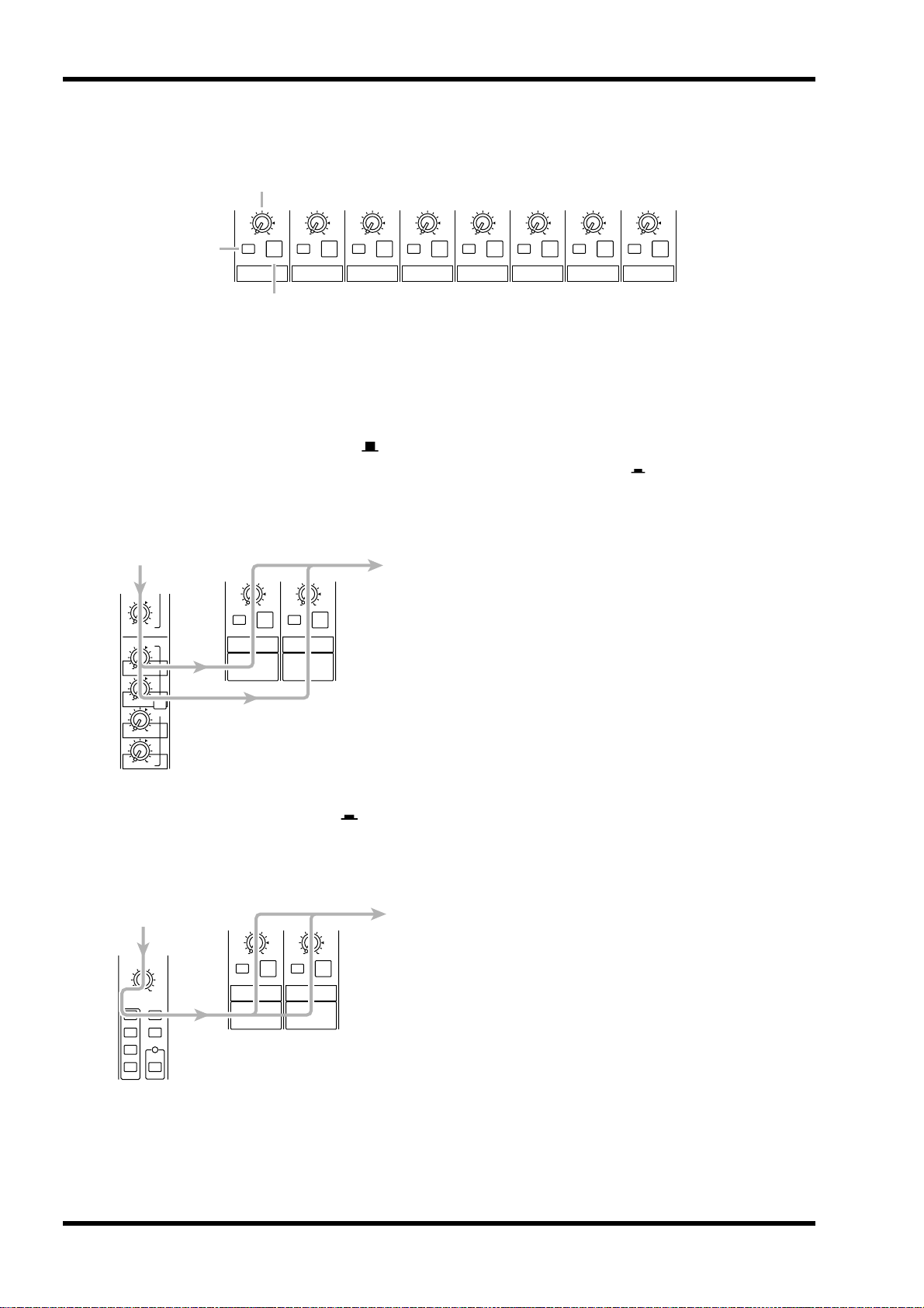
A7/G1–A14/G8 section
1
2
010
LEVEL
ON
A7 / G1
010
LEVEL
ON
AFL
A8 / G2
010
LEVEL
ON
AFL
AFL
A9 / G3
3
These output channels control the signals of AUX
buses 7–14 or GROUP buses 1–8. You can use the
GROUP/AUX FLIP switch (page 14) to select the signals that will be controlled.
■ GROUP/AUX FLIP switch= GROUP ( )
The signals of AUX buses 7–14 will be sent to channels A7/G1–A14/G8 respectively, and will be output
individually from the AUX/GRP OUT A7/G1–A14/
G8 jacks.
AUX5
010
AUX6
010
AUX7
010
AUX8
PRE
010
AUX9
010
AUX10
010
LEVEL
ON
AFL
A7 / G1
010
LEVEL
ON
AFL
A8 / G2
010
LEVEL
ON
AFL
A10 / G4
010
LEVEL
ON
A11 / G5
010
LEVEL
ON
AFL
A12 / G6
010
LEVEL
ON
AFL
A13 / G7
010
LEVEL
ON
AFL
AFL
A14 / G8
A LEVEL control
This adjusts the output level of AUX/GRP OUT A7/
G1–A14/G8. The “▲” position is nominal level.
B ON switch
This turns AUX/GRP OUT A7/G1–A14/G8 on/off.
When the switch is on ( ), the signals from the A7/
G1–A14/G8 section will be output from the AUX
OUT A7/G1–A14/G8 jacks respectively.
C AFL switch
This switch is used to monitor the signal from the
AUX/GRP OUT A7/G1–A14/G8 section via the
MONITOR OUT/PHONES jacks. If all the input
channel PFL switches are off, you can turn on this
AFL switch to monitor the corresponding signal of
the A7/G1–A14/G8 section from the MONITOR
OUT/PHONES jacks. You can use the MASTER PFL
switch of the monitor section to switch the monitor
signal between pre/post-fader (LEVEL control).
■ GROUP/AUX FLIP switch= AUX ( )
The signals of GROUP buses 1–8 will be sent to channels A7/G1–A14/G8 respectively, and output individually from the AUX/GRP OUT A7/G1–A14/G8 jacks.
PAN
LCR
ODD EVEN
1-2
3-4
5-6
7-8
ST
MONO
LCR
010
LEVEL
ON
A7 / G1
010
LEVEL
ON
AFL
AFL
A8 / G2
10 M2500—Owner’s Manual
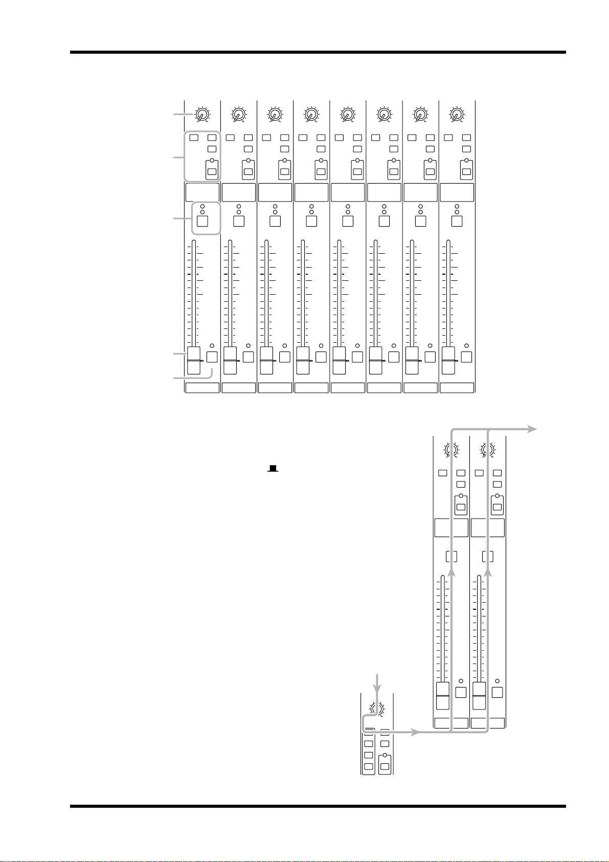
G1/A7–G8/A14 section
Control panel
4
5
6
7
8
PAN
LCR
MATRIX ST
MONO
CHECK
ON
ON/EDIT
10
5
0
5
10
20
30
40
50
60
G1 / A7
LCR
AFL
PAN
LCR
MATRIX ST
MONO
CHECK
ON
ON/EDIT
10
5
0
5
10
20
30
40
50
60
G2 / A8
LCR
AFL
PAN
LCR
MATRIX ST
MONO
CHECK
ON
ON/EDIT
10
5
0
5
10
20
30
40
50
60
G3 / A9
LCR
AFL
PAN
LCR
MATRIX ST
MONO
CHECK
ON
ON/EDIT
10
5
0
5
10
20
30
40
50
60
G4 / A10
LCR
AFL
PAN
LCR
MATRIX ST
MONO
CHECK
ON
ON/EDIT
10
5
0
5
10
20
30
40
50
60
G5 / A11
LCR
AFL
PAN
LCR
MATRIX ST
MONO
CHECK
ON
ON/EDIT
10
5
0
5
10
20
30
40
50
60
G6 / A12
LCR
AFL
PAN
LCR
MATRIX ST
CHECK
ON
ON/EDIT
10
5
0
5
10
20
30
40
50
60
G7 / A13
MONO
LCR
AFL
PAN
LCR
MATRIX ST
CHECK
ON
ON/EDIT
10
5
0
5
10
20
30
40
50
60
G8 / A14
MONO
LCR
AFL
These are the output channels that control GROUP
buses 1–8 or AUX buses 7–14. Use the GROUP/AUX
FLIP switch (page 14) to select which signals will be
controlled.
■ GROUP/AUX FLIP switch= GROUP ( )
The signals of GROUP buses 1–8 will be sent to channels G1/A7–G8/A14 respectively, and will be output
individually from the GRP/AUX OUT G1/A7–G8/
A14 jacks.
PAN
LCR
ODD EVEN
1-2
3-4
5-6
7-8
MONO
LCR
PAN
MATRIX ST
G1 / A7
ST
LCR
ON/EDIT
10
5
0
5
10
20
30
40
50
60
MONO
LCR
CHECK
ON
AFL
PAN
LCR
MATRIX ST
MONO
CHECK
ON
ON/EDIT
10
5
0
5
10
20
30
40
50
60
G2 / A8
LCR
AFL
M2500—Owner’s Manual 11
Control panel
■ GROUP/AUX FLIP switch= AUX ( )
The signals of AUX buses 7–14 will be sent to channels G1/A7–G8/A14 respectively, and will be output
individually from the GRP/AUX OUT G1/A7–G8/
A14 jacks.
AUX5
010
AUX6
010
AUX7
010
AUX8
PRE
010
AUX9
010
AUX10
PAN
MATRIX ST
G1 / A7
LCR
ON/EDIT
10
5
0
5
10
20
30
40
50
60
MONO
LCR
CHECK
ON
AFL
PAN
LCR
MATRIX ST
MONO
CHECK
ON
ON/EDIT
10
5
0
5
10
20
30
40
50
60
G2 / A8
LCR
AFL
D PAN control
This adjusts the pan of the signal that is sent from the
G1/A7–G8/A14 section to the STEREO or MONO/C
bus. The function of the PAN control will change as
follows, depending on the setting of the channel
assign switch (5).
● When the ST switch is on
PAN will adjust the pan of the signal that is sent from
each channel to the STEREO L/R bus.
● When the LCR switch is on
PAN will adjust the pan of the signal that is sent from
each channel to the STEREO L/R bus and MONO/C
bus.
E Channel assign switches
These switches assign the post-fader post-PAN signal
to the desired bus.
• ST (stereo) switch
If this switch is on ( ), the post-PAN signal of the
output channel will be sent to the STEREO bus.
• MONO (monaural) switch
If this switch is on ( ), the signal of the output
channel will be sent to the MONO/C bus.
• LCR switch
If this switch is on, the indicator above the switch will
light, and the post-PAN signal of the output channel
will be sent to the STEREO bus and the MONO/C
bus.
• MATRIX switch
IF this switch is on ( ), the signal of the output
channel will be sent to the corresponding MATRIX
bus.
Note:
• The LCR switch takes priority over the ST/
MONO switch. If the LCR switch is on, the
post-PAN signal of the G1/A7–G8/A14 section
will be sent to the STEREO bus (L/R) and
MONO/C bus regardless of the on/off status of
the ST/MONO switch. (Refer to response curve
diagram 1 on page 4.)
• If the LCR switch is off, the ST/MONO switch
will function as a conventional channel assign
switch. If ST is on, the post-PAN signal of the
G1/A7–G8/A14 section will be sent to the ST
bus. If the MONO switch is on, the signal of
the G1/A7–G8/A14 section will be sent directly
to the MONO/C bus. (Refer to response curve
diagram 2 on page 4.)
12 M2500—Owner’s Manual
Control panel
G7/A1
G1/A7
Same as
MONITOR
ST
LR
MONO
MONO
RL
ST
PFL AFL
ON
ON
(PFL)
to METER
to METER
from CPU
INPUT
GROUP/AUX FLIP
AUX
GROUP
MATRIX
and
and
AUX/GRP A8/G2-A14/G8
GRP/AUX G2/A8-G8/A14
G1/A7
A7/G1
G1/A7
0dB
INSERT I/O
AUX/GRP OUT
+4dB
GRP/AUX OUT
+4dB
ST
MASTER
LR
MONO
SUB IN
RLLR
MONO/C
STEREO
LR
MONO/C
STEREO
MATRIX
G8/A14
G7/A13
G6/A12
G5/A11
G4/A10
G3/A9
G2/A8
G1/A7
Control
ON/EDIT
CHECK
ON
LEVEL
ON
AFL
AFL
PAN
LCR
ST
MONO
AUXGROUP
1413121110
9
23456788765432
11
6
1
2
3
8
5
4
7
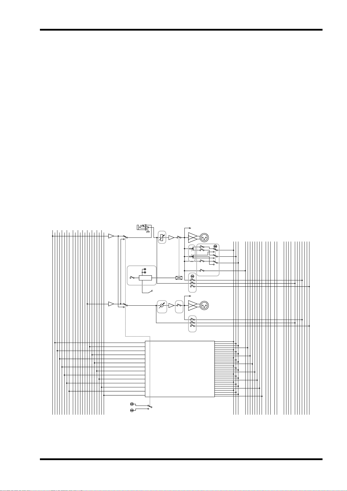
F ON/EDIT switch / ON, CHECK indicators
The function of this switch and these indicators will
change depending on the mode of the M2500.
● In normal mode
You can use the ON/EDIT switch to turn each G1/
A7–G8/A14 channel on/off. When the channel is
switched on/off, the ON indicator will be lit/dark to
indicate the status. Channels that are switched off will
not send any signals to the STEREO, MONO/C, or
MATRIX buses.
● In check mode
When a scene (which contains the on/off state of the
ON/EDIT switches) is selected, the on/off status
memorized in that scene will be indicated by the lit/
dark status of the CHECK indicator. In check mode,
you can also use the ON/EDIT switch to switch the
CHECK indicator between lit/dark. (The current on/
off setting will not be affected.) For details on check
mode, refer to page 32.
G Fader
This adjusts the output level of the GRP/AUX OUT.
H AFL (after fader listen) switch
This switch allows you to monitor the signal of the
G1/A7–G8/A14 section from the MONITOR OUT/
PHONES jacks. If the input channel PFL switches are
all off, turning this AFL switch on (the indicator
above the switch will light) will allow you to monitor
the corresponding G1/A7–G8/A14 section signal
from the MONITOR OUT/PHONES jacks. The
monitor signal can be switched between pre/postfader using the MASTER PFL switch of the monitor
section.
M2500—Owner’s Manual 13
Control panel
GROUP/AUX FLIP switch
The M2500 provides a GROUP/
AUX FLIP switch that
exchanges the output destinations of GROUP buses 1–8 and
AUX buses 7–14.
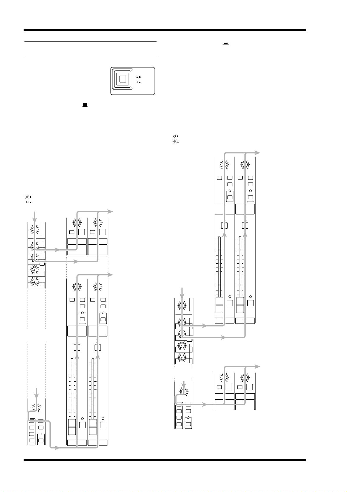
● When GROUP ( ) is selected
The signals of GROUP buses 1–8 will be routed
through the G1/A7–G8/A14 section, and sent to the
GROUP/AUX OUT jacks, the STEREO bus, MONO/C,
and MATRIX buses. The signals of AUX buses 7–14 will
be routed through the A7/G1–A14/G8 section, and sent
to the AUX GRP OUT jacks. With this setting, AUX
buses 7–14 can be used as conventional AUX buses, and
GROUP buses 1–8 can be used as group buses. This setting is more convenient when you are using the M2500
as a main console, since you will be able to use the 100
mm faders to control the group buses.
GROUP
When GROUP is selected
AUX
GROUP/AUX FLIP
GROUP
AUX
● When AUX ( ) is selected
The signals of GROUP buses 1–8 will be routed
through the A7/G1–A14/G8 section and sent to the
AUX/GRP OUT jacks. The signals of AUX buses 7–14
will be routed through the G1/A7–G8/A14 section,
and sent to the GROUP/AUX OUT jacks, the STEREO bus, MONO/C, and MATRIX buses.
This setting is more convenient when you are using
the M2500 as a “monitor console” to control individual monitor levels on stage, since you will be able to
use the 100 mm faders to control each of the AUX
buses (1–14).
GROUP
When AUX is selected
AUX
PAN
LCR
MATRIX ST
MONO
PAN
LCR
MATRIX ST
LCR
GRP/AUX OUT jacks
STEREO bus
MONO/C bus
MATRIX bus
MONO
LCR
AUX5
010
AUX6
010
AUX7
010
AUX8
PRE
010
AUX9
010
AUX10
Input
channel
PAN
LCR
ODD EVEN
1-2
ST
MONO
3-4
5-6
LCR
7-8
010
LEVEL
ON
A7 / G1
PAN
LCR
MATRIX ST
CHECK
ON
ON/EDIT
10
5
0
5
10
20
30
40
50
60
G1 / A7
AFL
MONO
LCR
AFL
010
LEVEL
ON
A8 / G2
PAN
LCR
MATRIX ST
MONO
CHECK
ON
ON/EDIT
10
5
0
5
10
20
30
40
50
60
G2 / A8
AUX/GRP OUT jacks
AFL
A7/G1–A14/G8 section
GRP/AUX OUT jacks
STEREO bus
MONO/C bus
MATRIX bus
LCR
AFL
G1/A7–G8/A14 section
AUX5
010
AUX6
010
AUX7
010
AUX8
010
AUX9
010
AUX10
Input
channel
PAN
LCR
ODD EVEN
1-2
MONO
3-4
5-6
LCR
7-8
PRE
ST
CHECK
ON
ON/EDIT
10
5
0
5
10
20
30
40
50
60
G1 / A7
010
LEVEL
ON
A7 / G1
CHECK
ON
ON/EDIT
10
5
0
5
10
20
30
40
50
60
AFL
G2 / A8
AFL
G1/A7–G8/A14 section
AUX/GRP OUT jacks
010
LEVEL
ON
AFL
A8 / G2
AFL
A7/G1–A14/G8 section
14 M2500—Owner’s Manual
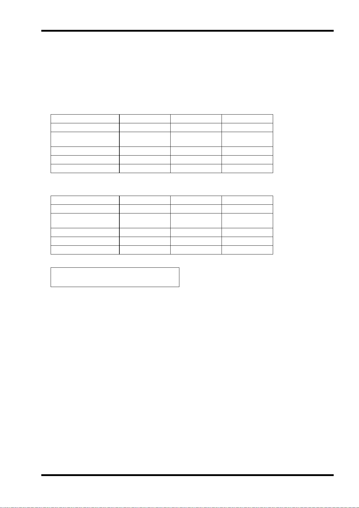
When you change the setting of the GROUP/AUX
FLIP switch, numerous functions of the output channels of GROUP buses 1–8 and AUX buses 7–14 will
change in addition to the faders. The functions available for the output channels of each bus are shown
below for each setting (GROUP/AUX) of the
GROUP/AUX FLIP switch.
• GROUP/AUX FLIP switch= GROUP (principal application: main console)
Output channel GROUP buses 1–8 AUX buses 1–6 AUX buses 7–14
Master control 100 mm faders 100 mm faders Rotary faders
Channel assign switch
(MATRIX/ST/MONO/LCR)
PAN control ❍✕✕
Mute switch ON/EDIT ON ON
INSERT I/O ❍❍✕
❍✕✕
• GROUP/AUX FLIP switch= AUX (principal application: monitor console)
Control panel
Output channel GROUP buses 1–8 AUX buses 1–6 AUX buses 7–14
Master control Rotary faders 100 mm faders 100 mm faders
Channel assign switch
(MATRIX/ST/MONO/LCR)
PAN control ✕✕❍
Mute switch ON ON ON/EDIT
INSERT I/O ✕❍❍
✕✕❍
Note: The output channels of AUX buses 1–6 are
not affected by the GROUP/AUX FLIP switch.
M2500—Owner’s Manual 15
Control panel
Stereo/monaural master
section
This section controls the signals that are output from
the rear panel ST OUT L/R and MONO/C OUT jacks
(page 28).
● In check mode
When a scene (which contains the on/off state of the
ON/EDIT switches) is selected, the on/off status
memorized in that scene will be indicated by the lit/
dark status of the CHECK indicator. In check mode,
you can also use the ON/EDIT switch to switch the
CHECK indicator between lit/dark. (The current on/
off setting will not be affected.) For details on check
mode, refer to page 32.
CHECK
ON
AFL
5
6
8
7
1
2
3
4
MATRIX MATRIX
CHECK
ON
10
5
0
5
10
20
30
40
50
60
AFL
MONO/CSTEREO
ON/EDITON/EDIT
10
5
0
5
10
20
30
40
50
60
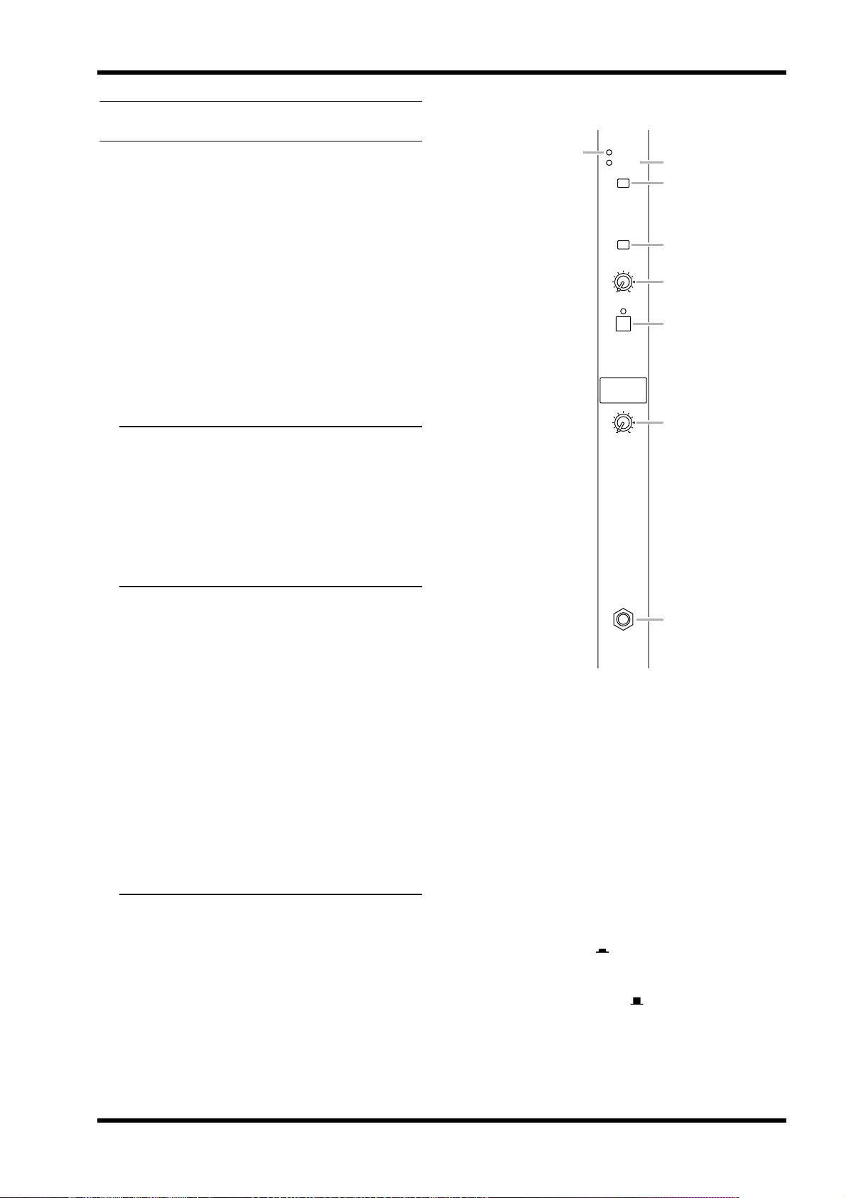
STEREO section
A MATRIX switch
If this switch is on ( ), the post-fader ST OUT L/R
signal will be sent to the matrix (page 18).
B ON/EDIT switch / ON, CHECK indicators
The function of this switch and these indicators will
change depending on the mode of the M2500.
● In normal mode
You can use the ON/EDIT switch to turn ST OUT L/
R on/off. When this is switched on/off, the ON indicator will be lit/dark to indicate the status. Channels
that are switched off will not send any signals to the
ST OUT L/R jacks or to the matrix.
C Fader
This adjusts the ST OUT L/R output level.
D AFL switch
Using this switch, the signal sent to the ST OUT L/R
jacks can be monitored from the MONITOR OUT/
PHONES jacks. If the PFL switches of all input channels are off, turning this AFL switch on (the indicator
above the switch will light) will allow you to monitor
the output signal of the STEREO section from the
MONITOR OUT/PHONES jacks. Use the MASTER
PFL switch of the monitor section to switch the monitor signal between pre/post-fader.
MONO/C section
E MATRIX switch
If this switch is on ( ), the post-fader MONO/C signal will be sent to the matrix (page 18).
F ON/EDIT switch / ON, CHECK indicators
The function of this switch and these indicators will
change depending on the mode of the M2500.
● In normal mode
You can use the ON/EDIT switch to turn MONO/C
OUT on/off. When this is switched on/off, the ON
indicator will be lit/dark to indicate the status. Channels that are switched off will not send any signals to
the MONO/C jack or to the matrix.
● In check mode
When a scene (which contains the on/off state of the
ON/EDIT switches) is selected, the on/off status
memorized in that scene will be indicated by the lit/
dark status of the CHECK indicator. In check mode,
you can also use the ON/EDIT switch to switch the
CHECK indicator between lit/dark. (The current on/
off setting will not be affected.) For details on check
mode, refer to page 32.
G Fader
This adjusts the output level of MONO/C.
16 M2500—Owner’s Manual
H AFL switch
Using this switch, the signal sent to the MONO/C
OUT jack can be monitored from the MONITOR
OUT/PHONES jacks. If the PFL switches of all input
channels are off, turning this AFL switch on (the
indicator above the switch will light) will allow you to
monitor the output signal of the MONO/C section
from the MONITOR OUT/PHONES jacks. Use the
MASTER PFL switch of the monitor section to switch
the monitor signal between pre/post-fader.
Note: When using the AFL switch to monitor the
signal of the MONO/C section from the MONITOR OUT jacks, be aware that the monitor signal
will not be output from the MONITOR OUT
MONO/C jack, but will be output monaurally
from the MONITOR OUT L/R jacks.
Control panel
STEREO
LR
MONO/C
INSERT I/O
ON/EDIT
2
INSERT I/O
INSERT I/O
MONO/C
ON/EDIT
ST R
ST L
MONO/C
RLLR
SUB IN
INPUT
(PFL)
MONO
LR
MONITOR
PFL AFL
ST
ON
MASTER
ST
MONO
RL
MONO
LR
ST
ON
MASTER
PFL
L
MONITOR
L+R LEVEL
ON
MASTERINPUT
PHONES
OUT
+4dB
R
MONO/C
MATRIX
STEREO
G8/A14
G7/A13
G6/A12
G5/A11
G4/A10
G3/A9
G2/A8
G1/A7
0dB
ST OUT
+4dB
1
CHECK
ON
Control
from CPU
AFL
0dB
ON
0dB
Control
CHECK
ON
from CPU
736
L
4
AFL
ST OUT
+4dB
R
+4dB
MONO/C
MATRIX
5
MATRIX
8
M2500—Owner’s Manual 17
Control panel
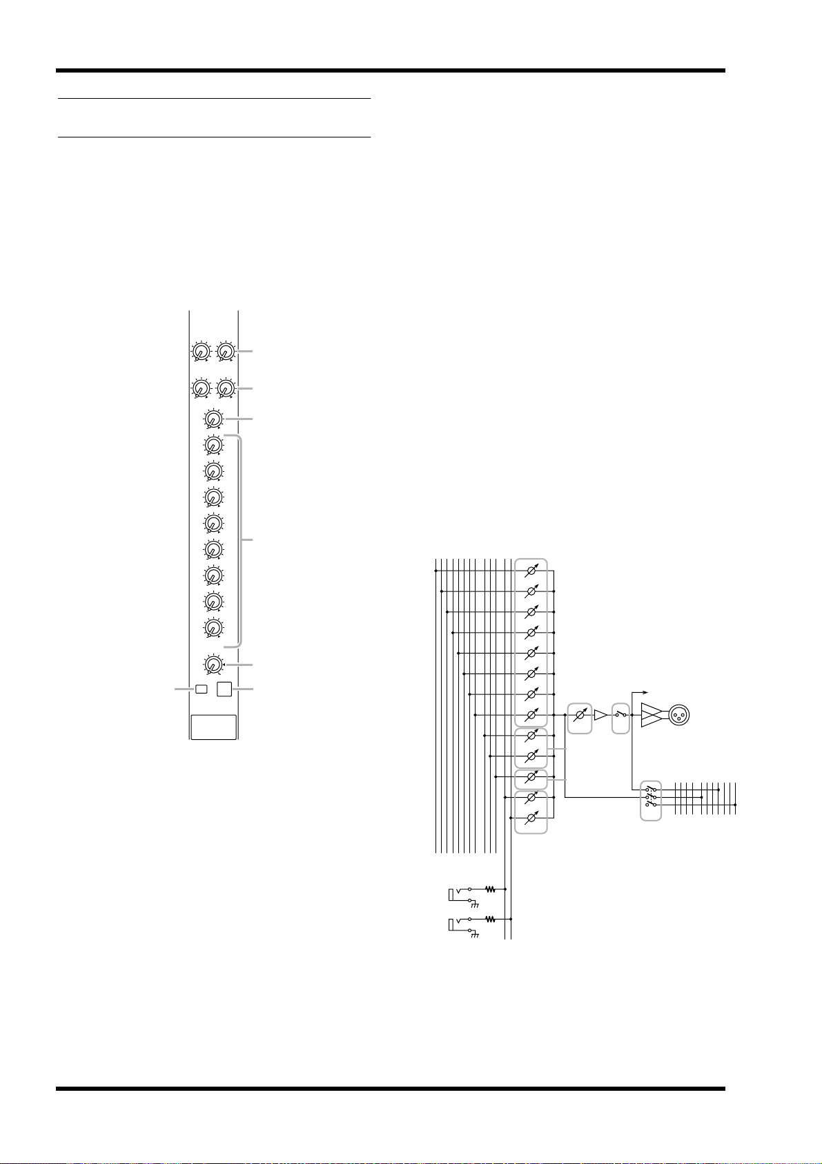
Matrix section
The M2500 provides an eight channel matrix section
that allows the output signals from the G1/A7–G8/
A14 section, the output signals from the stereo/monaural master section, and the input signals from the
SUB IN MATRIX jacks to be mixed at a desired level.
Matrix 1–8 are output individually from MATRIX
OUT jacks 1–8 (page 27), and can be used as mixes
for foldback or individual monitor systems.
1
0L0
SUB IN
R
2
0L0
ST
R
0
MONO/C
0
G1 / A7
0
G2 / A8
0
G3 / A9
0
G4 / A10
0
G5 / A11
0
G6 / A12
0
G7 / A13
0
G8 / A14
010
LEVEL
6
ON
MATRIX 1
A SUB IN L/R control
These adjust the signal levels that are input to the
matrix from the rear panel SUB IN MATRIX jacks
(page 28). The “▲” position is nominal level (0 dB).
3
4
5
7
AFL
D G1/A7–G8/A14 controls
When the MATRIX switches of the G1/A7–G8/A14
section (page 11) are on, these controls adjust the
level of the signal that is sent from the corresponding
GRP/AUX OUT to the matrix. The “▲” position is
nominal level.
E LEVEL control
This adjusts the final output level of the matrix. The
“▲” position is nominal level.
F ON switch
This switches the output of the matrix on/off.
G AFL switch
Using this switch, the signal of the matrix can be
monitored from the MONITOR OUT/PHONES
jacks. If the PFL switches of all input channels are off,
turning this AFL switch on will allow you to monitor
the output signal of the corresponding matrix from
the MONITOR OUT/PHONES jacks. Use the MASTER PFL switch of the monitor section to switch the
monitor signal between pre/post-fader (LEVEL control).
MATRIX
SUB IN
STEREO
4
MONO/C
G8/A14
G7/A13
G6/A12
G5/A11
G4/A10
G3/A9
G2/A8
G1/A7
RLLR
G1/A7
G2/A8
G7/A9
G7/A10
G7/A11
G7/A12
G7/A13
G8/A14
ST L
ST R
MONO/C
SUB IN L
SUB IN R
576
LEVEL
2
3
to METER
ON
AFL
1
INPUT
(PFL)
MONO
LR
MATRIX OUT
+4dB
1-8
MONITOR
PFL AFL
ST
MONO
ON
MASTER
ST
MONO
LR
RL
ST
ON
B ST L/R controls
When the MATRIX switch of the STEREO section
(page 16) is on, these controls adjust the level of the
signal that is sent from the STEREO section to the
matrix. The “▲” position is nominal level.
C MONO/C control
When the MATRIX switch of the MONO/C section
(page 16) is on, this control adjusts the level of the
signal that is sent from the MONO/C section to the
matrix. The “▲” position is nominal level.
18 M2500—Owner’s Manual
SUB IN
+4dB
MATRIX
L
R
Monitor section
PHONES
L+R
INPUT
MASTER
MASTER
PFL
ON
MONITOR
PHONES
010
LEVEL
010
2
3
4
5
7
8
6
1
In this section you can select the signal that will be
monitored from the MONITOR OUT jacks and the
PHONES jacks.
Monitor signal priority order
There is a priority order for the signals that can be
selected as monitor sources. While a higher priority
signal is being monitored, it is not possible to monitor signals of a lower priority. Multiple monitor
sources can be selected simultaneously if they are all
of the same priority level.
The priority order of the various monitor sources is
shown below.
Priority order 1
• Pre-fader signal of a monaural input channel
(PFL switch)
• Pre-fader signal of a stereo input channel
(PFL switch)
When a PFL switch is turned on, the pre-fader signal
of that input channel can be monitored from the
MONITOR OUT/PHONES jacks.
Control panel
Priority order 2
• Pre/post-fader signals of the AUX 1–6 section
(AFL switch)
• Pre/post-fader signals of the A7/G1–A14/G8 section (AFL switch)
• Pre/post-fader signals of the G1/A7–G8/A14 section (AFL switch)
• Pre/post-fader signals of the STEREO section
(AFL switch)
• Pre/post-fader signals of the MONO/C section
(AFL switch)
• Pre/post-fader signals of the matrix section
(AFL switch)
When a AFL switch of one of these sections is turned
on, the pre/post-fader signal of the corresponding
section can be monitored from the MONITOR OUT/
PHONES jacks.
Priority order 3
• ST OUT (L, R, MONO/C) output signals
If all PFL and AFL switches of priority orders 1 and 2
are off, the ST OUT (L, R, MONO/C) output signal
can be monitored from MONITOR OUT L, R, and
MONO/C.
The PHONES jack will monitor the ST OUT (L/R)
output signal.
A INPUT indicator
If even one of the input channel PFL switches are on,
this indicator will light. When this indicator is lit, you
are monitoring a signal of priority order 1.
B MASTER indicator
If even one of the AFL switches of the GROUP/AUX
master section, the stereo/monaural master section,
or the matrix section are on, this indicator will light.
In this case if the INPUT indicator (1) is dark, you
are monitoring the pre/post-fader signal from one of
the sections (priority order 2).
C MASTER PFL switch
If this switch is on ( ), the MONITOR MASTER
PFL signals (pre-fader signals of priority order 2) can
be monitored from the MONITOR OUT/PHONES
jacks. If this switch is off ( ), the MONITOR MASTER AFL signals (after-fader signals of priority order
2) can be monitored from the MONITOR OUT/
PHONES jacks.
M2500—Owner’s Manual 19
 Loading...