

Page 1

LS9-16/LS9-32
Owner’s Manual
EN
Page 2

FCC INFORMATION (U.S.A.)
1. IMPORTANT NOTICE: DO NOT MODIFY THIS
UNIT!
This product, when installed as indicated in the instructions
contained in this manual, meets FCC requirements. Modifications not expressly approved by Yamaha may void your
authority, granted by the FCC, to use the product.
2. IMPORTANT: When connecting this product to accesso-
ries and/or another product use only high quality shielded
cables. Cable/s supplied with this product MUST be used.
Follow all installation instructions. Failure to follow instructions could void your FCC authorization to use this product
in the USA.
3. NOTE: This product has been tested and found to comply
with the requirements listed in FCC Regulations, Part 15 for
Class “B” digital devices. Compliance with these requirements provides a reasonable level of assurance that your
use of this product in a residential environment will not
result in harmful interference with other electronic devices.
This equipment generates/uses radio frequencies and, if
not installed and used according to the instructions found in
the users manual, may cause interference harmful to the
operation of other electronic devices. Compliance with FCC
* This applies only to products distributed by YAMAHA CORPORATION OF AMERICA. (class B)
COMPLIANCE INFORMATION STATEMENT
(DECLARATION OF CONFORMITY PROCEDURE)
Responsible Party : Yamaha Corporation of America
Address : 6600 Orangethorpe Ave., Buena Park,
Telephone : 714-522-9011
Type of Equipment : DIGITAL MIXING CONSOLE
Model Name : LS9-16, LS9-32
This device complies with Part 15 of the FCC Rules.
Operation is subject to the following two conditions:
1) this device may not cause harmful interference, and
2) this device must accept any interference received including
interference that may cause undesired operation.
See user manual instructions if interference to radio reception is suspected.
* This applies only to products distributed by
YAMAHA CORPORATION OF AMERICA.
Calif. 90620
(FCC DoC)
regulations does not guarantee that interference will not
occur in all installations. If this product is found to be the
source of interference, which can be determined by turning
the unit “OFF” and “ON”, please try to eliminate the problem
by using one of the following measures:
Relocate either this product or the device that is being
affected by the interference.
Utilize power outlets that are on different branch (circuit
breaker or fuse) circuits or install AC line filter/s.
In the case of radio or TV interference, relocate/reorient the
antenna. If the antenna lead-in is 300 ohm ribbon lead,
change the lead-in to co-axial type cable.
If these corrective measures do not produce satisfactory
results, please contact the local retailer authorized to distribute this type of product. If you can not locate the appropriate retailer, please contact Yamaha Corporation of
America, Electronic Service Division, 6600 Orangethorpe
Ave, Buena Park, CA90620
The above statements apply ONLY to those products distributed by Yamaha Corporation of America or its subsidiaries.
IMPORTANT NOTICE FOR THE UNITED KINGDOM
Connecting the Plug and Cord
WARNING: THIS APPARATUS MUST BE EARTHED
IMPORTANT. The wires in this mains lead are coloured in
accordance with the following code:
As the colours of the wires in the mains lead of this apparatus
may not correspond with the coloured markings identifying the
terminals in your plug proceed as follows:
The wire which is coloured GREEN-and-YELLOW must be
connected to the terminal in the plug which is marked by the
letter E or by the safety earth symbol or colored GREEN or
GREEN-and-YELLOW.
The wire which is coloured BLUE must be connected to the
terminal which is marked with the letter N or coloured BLACK.
The wire which is coloured BROWN must be connected to the
terminal which is marked with the letter L or coloured RED.
• This applies only to products distributed by
Yamaha-Kemble Music (U.K.) Ltd.
GREEN-AND-YELLOW : EARTH
BLUE : NEUTRAL
BROWN : LIVE
(3 wires)
This product contains a battery that contains perchlorate material.
Perchlorate Material—special handling may apply,
See www.dtsc.ca.gov/hazardouswaste/perchlorate.
* This applies only to products distributed by YAMAHA CORPORATION OF AMERICA. (Perchlorate)
This product contains a high intensity lamp that contains
a small amount of mercury. Disposal of this material
may be regulated due to environmental considerations.
For disposal information in the United States, refer to
the Electronic Industries Alliance web site:
www.eiae.org
YAMAHA CORPORATION OF AMERICA.
LS9-16/32 Owner’s Manual
2
(mercury)* This applies only to products distributed by
Page 3

CAUTION
RISK OF ELECTRIC SHOCK
DO NOT OPEN
CAUTION: TO REDUCE THE RISK OF
ELECTRIC SHOCK, DO NOT REMOVE
COVER (OR BACK). NO USER-SERVICEABLE
PARTS INSIDE. REFER SERVICING TO
QUALIFIED SERVICE PERSONNEL.
The above warning is located on the rear or side of the unit.
IMPORTANT SAFETY INSTRUCTIONS
Explanation of Graphical Symbols
The lightning flash with arrowhead symbol
within an equilateral triangle is intended to
alert the user to the presence of uninsulated
“dangerous voltage” within the product’s
enclosure that may be of sufficient magnitude
to constitute a risk of electric shock to
persons.
The exclamation point within an equilateral
triangle is intended to alert the user to the
presence of important operating and
maintenance (servicing) instructions in the
literature accompanying the product.
1 Read these instructions.
2Keep these instructions.
3 Heed all warnings.
4 Follow all instructions.
5 Do not use this apparatus near water.
6 Clean only with dry cloth.
7 Do not block any ventilation openings. Install in
accordance with the manufacturer’s instructions.
8 Do not install near any heat sources such as radiators,
heat registers, stoves, or other apparatus (including
amplifiers) that produce heat.
9 Do not defeat the safety purpose of the polarized or
grounding-type plug. A polarized plug has two blades
with one wider than the other. A grounding type plug
has two blades and a third grounding prong. The wide
blade or the third prong are provided for your safety. If
the provided plug does not fit into your outlet, consult
an electrician for replacement of the obsolete outlet.
10 Protect the power cord from being walked on or
pinched particularly at plugs, convenience receptacles,
and the point where they exit from the apparatus.
11 Only use attachments/accessories specified by the
manufacturer.
12 Use only with the cart, stand,
tripod, bracket, or table
specified by the manufacturer,
or sold with the apparatus. When
a cart is used, use caution when
moving the cart/apparatus
combination to avoid injury from
tip-over.
13 Unplug this apparatus during lightning storms or when
unused for long periods of time.
14 Refer all servicing to qualified service personnel.
Servicing is required when the apparatus has been
damaged in any way, such as power-supply cord or
plug is damaged, liquid has been spilled or objects
have fallen into the apparatus, the apparatus has been
exposed to rain or moisture, does not operate
normally, or has been dropped.
WARNING
TO REDUCE THE RISK OF FIRE OR ELECTRIC SHOCK, DO NOT EXPOSE THIS APPARATUS TO RAIN OR MOISTURE.
(98-6500)
ADVARSEL!
Lithiumbatteri—Eksplosionsfare ved fejlagtig
håndtering. Udskiftning må kun ske med batteri af
samme fabrikat og type. Levér det brugte batteri
tilbage til leverandoren.
VARNING
Explosionsfara vid felaktigt batteribyte. Använd
samma batterityp eller en ekvivalent typ som rekommenderas av apparattillverkaren. Kassera
använt batteri enligt fabrikantens instruktion.
VAROITUS
Paristo voi räjähtää, jos se on virheellisesti asennettu. Vaihda paristo ainoastaan laitevalmistajan
suosittelemaan tyyppiin. Hävitä käytetty paristo
valmistajan ohjeiden mukaisesti.
(lithium caution)
NEDERLAND / THE NETHERLANDS
• Dit apparaat bevat een lithium batterij voor geheugen back-up.
• This apparatus contains a lithium battery for memory back-up.
• Raadpleeg uw leverancier over de verwijdering van de batterij op het
moment dat u het apparaat ann het einde van de levensduur of gelieve
dan contact op te nemen met de vertegenwoordiging van Yamaha in
uw land.
•For the removal of the battery at the moment of the disposal at the end
of life please consult your retailer or Yamaha representative office in
your country.
• Gooi de batterij niet weg, maar lever hem in als KCA.
• Do not throw away the battery. Instead, hand it in as small chemical
waste.
(lithium disposal)
LS9-16/32 Owner’s Manual
3
Page 4
PRECAUTIONS
PLEASE READ CAREFULLY BEFORE PROCEEDING
* Please keep this manual in a safe place for future reference.
WARNING
Always follow the basic precautions listed below to avoid the possibility of serious injury or even death from
electrical shock, short-circuiting, damages, fire or other hazards. These precautions include, but are not limited
to, the following:
Power supply/Power cord
• Only use the voltage specified as correct for the device. The required
voltage is printed on the name plate of the device.
• Use only the included power cord.
If you intend to use the device in an area other than in the one you
purchased, the included power cord may not be compatible. Please check
with your Yamaha dealer.
• Do not place the power cord near heat sources such as heaters or radiators,
and do not excessively bend or otherwise damage the cord, place heavy
objects on it, or place it in a position where anyone could walk on, trip over,
or roll anything over it.
• Be sure to connect to an appropriate outlet with a protective grounding
connection. Improper grounding can result in electrical shock.
Do not open
• Do not open the device or attempt to disassemble the internal parts or
modify them in any way. The device contains no user-serviceable parts. If it
should appear to be malfunctioning, discontinue use immediately and have
it inspected by qualified Yamaha service personnel.
CAUTION
Water warning
• Do not expose the device to rain, use it near water or in damp or wet
conditions, or place containers on it containing liquids which might spill
into any openings.
• Never insert or remove an electric plug with wet hands.
If you notice any abnormality
• If the power cord or plug becomes frayed or damaged, or if there is a
sudden loss of sound during use of the device, or if any unusual smells or
smoke should appear to be caused by it, immediately turn off the power
switch, disconnect the electric plug from the outlet, and have the device
inspected by qualified Yamaha service personnel.
• If this device should be dropped or damaged, immediately turn off the
power switch, disconnect the electric plug from the outlet, and have the
device inspected by qualified Yamaha service personnel.
Always follow the basic precautions listed below to avoid the possibility of physical injury to you or others, or
damage to the device or other property. These precautions include, but are not limited to, the following:
Power supply/Power cord
• Remove the electric plug from the outlet when the device is not to be used
for extended periods of time, or during electrical storms.
• When removing the electric plug from the device or an outlet, always hold
the plug itself and not the cord. Pulling by the cord can damage it.
Location
• When transporting or moving the device, do not hold the display.
Improper transportation can result in injury or damage to the device itself.
• Before moving the device, remove all connected cables.
• When setting up the product, make sure that the AC outlet you are using is
easily accessible. If some trouble or malfunction occurs, immediately turn
off the power switch and disconnect the plug from the outlet. Even when the
power switch is turned off, electricity is still flowing to the product at the
minimum level. When you are not using the product for a long time, make
sure to unplug the power cord from the wall AC outlet.
•Avoid setting all equalizer controls and faders to their maximum.
Depending on the condition of the connected devices, doing so may cause
feedback and may damage the speakers.
• Do not expose the device to excessive dust or vibrations, or extreme cold
or heat (such as in direct sunlight, near a heater, or in a car during the day)
to prevent the possibility of panel disfiguration or damage to the internal
components.
• Do not place the device in an unstable position where it might accidentally
fall over.
• Do not block the vents. This device has ventilation holes at the top and rear
to prevent the internal temperature from becoming too high. In particular,
do not place the device on its side or upside down. Inadequate ventilation
can result in overheating, possibly causing damage to the device(s), or
even fire.
• Do not use the device in the vicinity of a TV, radio, stereo equipment,
mobile phone, or other electric devices. Doing so may result in noise, both
in the device itself and in the TV or radio next to it.
(5)-4 1/2
LS9-16/32 Owner’s Manual
4
Page 5

Connections
• Before connecting the device to other devices, turn off the power for all
devices. Before turning the power on or off for all devices, set all volume
levels to minimum.
• Be sure to connect to a properly grounded power source. A ground screw is
provided on the rear panel of this device for maximum safety and shock
prevention. If the mains outlet is not grounded, be sure to connect the
ground screw to a confirmed ground point before plugging the device into
the mains. Improper grounding can result in electrical shock.
Handling caution
• When turning on the AC power in your audio system, always turn on the
power amplifier LAST, to avoid speaker damage. When turning the power
off, the power amplifier should be turned off FIRST for the same reason.
• Do not insert your fingers or hands in any gaps or openings on the device
(vents, etc.).
•Avoid inserting or dropping foreign objects (paper, plastic, metal, etc.) into
any gaps or openings on the device (vents, etc.) If this happens, turn off the
power immediately and unplug the power cord from the AC outlet. Then
have the device inspected by qualified Yamaha service personnel.
• Do not apply oil, grease, or contact cleaner to the faders. Doing so may
cause problems with electrical contact or fader motion.
• Do not use the device or headphones for a long period of time at a high or
uncomfortable volume level, since this can cause permanent hearing loss.
If you experience any hearing loss or ringing in the ears, consult a
physician.
• Do not rest your weight on the device or place heavy objects on it, and
avoid use excessive force on the buttons, switches or connectors.
Backup battery
• This device has a built-in backup battery. When you unplug the power cord
from the AC outlet, the current scene data and library data is retained.
However, if the backup battery fully discharges, this data will be lost. When
the backup battery is running low, the LCD display indicates “Low Battery!”
when you starting up the system (the Battery field also indicates “LOW” or
“NO” in the MISC SETUP screen.) In this case, immediately save the data
to a USB memory, then have qualified Yamaha service personnel replace
the backup battery.
XLR-type connectors are wired as follows (IEC60268 standard): pin 1: ground, pin 2: hot (+), and pin 3: cold (-).
Yamaha cannot be held responsible for damage caused by improper use or modifications to the device, or data that is lost or destroyed.
Always turn the power off when the device is not in use.
The performance of components with moving contacts, such as switches, volume controls, and connectors, deteriorates over time. Consult qualified Yamaha service
personnel about replacing defective components.
(5)-4 2/2
LS9-16/32 Owner’s Manual
5
Page 6

Contents
1. Introduction 9
Thank you ...................................................................9
An overview of the LS9..............................................9
Differences between the LS9-16 and LS9-32 ......... 11
Number of INPUT channels................................. 11
Rear panel ........................................................... 11
Top panel............................................................. 12
Other.................................................................... 13
The LS9’s channel structure ...................................13
About the MIX bus types (VARI / FIXED)................14
About word clock .....................................................14
Conventions in this manual.....................................14
About the firmware version.....................................14
2. Parts and their function 15
Top panel...................................................................15
Rear panel ................................................................. 23
Front panel................................................................26
3. Basic operations on the LS9 27
Basic operations in the top panel...........................27
About the [HOME] key.........................................27
Selecting the fader layer......................................27
Using the SELECTED CHANNEL section...........29
Selecting functions ..............................................29
Viewing the display .................................................. 30
Constant display area..........................................30
Main area............................................................. 31
The on-screen user interface............................... 32
Assigning a name..................................................... 34
Using the tool buttons .............................................35
About the tool buttons.......................................... 35
Using libraries......................................................35
Initializing settings ...............................................38
Copying and pasting settings ..............................39
Comparing two sets of settings ...........................39
4. Connections and setup 41
Connections.............................................................. 41
Installing an option card..........................................44
Setup required when starting up ............................45
Returning the current scene to the initial state ....45
Word clock connection and settings .................... 46
HA (head amp) settings.......................................47
Sending an input channel signal
to the STEREO bus.......................................... 50
5. Input channel operations 53
Signal flow for input channels.................................53
Specifying the channel name / icon........................55
HA (head amp) settings............................................57
Sending the signal from
an input channel to the STEREO/MONO bus......58
Sending the signal from
an input channel to a MIX bus..............................62
Using the SELECTED CHANNEL section ...........62
Using a popup window.........................................64
Using the faders (SENDS ON FADER mode) .....65
6. Output channel operations 67
Signal flow for output channels ..............................67
Specifying the channel name / icon........................69
Sending signals from MIX channels
to the STEREO/MONO bus ...................................71
Sending signals from MIX channels
and STEREO/MONO channels
to MATRIX buses...................................................75
Using the SELECTED CHANNEL section ...........75
Using a popup window.........................................77
Using the faders (SENDS ON FADER mode) .....78
7. Operations in
the SELECTED CHANNEL section 81
About the SELECTED CHANNEL section...............81
About the SELECTED CH VIEW screen..................82
Operations in the SELECTED CHANNEL section..83
8. Custom fader layer 91
About the custom fader layer ..................................91
Assigning channels to the custom fader layer ......92
9. Input/output patching 95
Changing the output patching.................................95
Changing the input patching ...................................99
Inserting an external device into a channel .........101
Directly outputting an INPUT channel ..................103
10. USB memory recorder 105
About the USB memory recorder..........................105
Assigning channels to
the input/output of the recorder.........................106
Recording to USB memory ....................................108
Playing back audio files from USB memory ........110
Editing the title list..................................................112
Linking scene recall with audio file playback ......113
LS9-16/32 Owner’s Manual
6
Page 7

Contents
11. EQ and Dynamics 115
About EQ and dynamics........................................115
Using EQ .................................................................115
Using dynamics......................................................117
Using the EQ/Dynamics libraries..........................120
EQ library........................................................... 120
Dynamics library ................................................ 120
12. Grouping and linking 121
About mute groups ................................................121
Using mute groups................................................. 121
Using the MUTE GROUP screen
to operate mute groups .................................. 121
Using the SELECTED CH VIEW screen
to specify mute groups ................................... 122
Using the Mute Safe function ............................123
The Channel Link function ....................................124
Linking the desired input channels ....................124
Copying, moving, or initializing a channel...........126
Copying the parameters of a channel................ 126
Moving the parameters of a channel .................127
Initializing the parameters of a channel ............. 128
13. Scene memory 129
About scene memories..........................................129
Using scene memories ..........................................129
Storing a scene.................................................. 129
Recalling a scene ..............................................131
Using user-defined keys to recall ......................132
Editing scene memories ........................................ 134
Sorting and renaming scene memories.............134
Scene memory editing.......................................136
Copying/pasting a scene ...................................136
Clearing a scene................................................ 137
Cutting a scene.................................................. 138
Inserting a scene ...............................................138
Using the Focus function ......................................139
Using the Recall Safe function.............................. 140
Using the Fade function.........................................143
15. Talkback / Oscillator 151
About talkback and oscillator................................151
Using talkback ........................................................151
Using the oscillator ................................................153
16. Meters 155
Using the METER screen .......................................155
17. Graphic EQ and effects 157
About the virtual rack.............................................157
Mounting a GEQ or effect in the virtual rack ......158
Graphic EQ operations...........................................161
About the graphic EQ.........................................161
Inserting a GEQ in a channel.............................161
Using the 31 Band GEQ ....................................163
Using the Flex15GEQ ........................................164
About the internal effects ......................................166
Using an internal effect via send/return .............167
Inserting an internal effect into a channel ..........168
Editing the internal effect parameters ................170
Using the Tap Tempo function...........................172
Using the Freeze effect......................................173
Using the graphic EQ and effect libraries ............174
GEQ library ........................................................174
Effect library .......................................................174
Using an external head amp ..................................175
Remotely controlling an external head amp.......175
18. MIDI 177
MIDI functionality on the LS9 ................................177
Basic MIDI settings.................................................178
Using program changes
to recall scenes and library items......................180
Using control changes to control parameters .....183
Using parameter changes
to control parameters .........................................185
Using MMC (MIDI Machine Control)
to operate the USB memory recorder ...............186
14. Monitor/Cue 145
About the monitor/cue functions..........................145
Using the Monitor function.................................... 146
Using the Cue function .......................................... 148
About cue groups ..............................................148
Operating the Cue function................................ 149
19. User settings (Security) 187
User Level settings.................................................187
User types and user authentication keys ...........187
Setting the Administrator password ...................188
Creating a user authentication key ....................188
Logging-in ..........................................................189
Changing the password .....................................191
Editing a user authentication key .......................192
Changing the user level .....................................192
LS9-16/32 Owner’s Manual
7
Page 8

Contents
Preferences.............................................................194
User-defined keys ..................................................196
Console lock ........................................................... 197
Locking the console...........................................197
Unlocking the console .......................................198
Specifying the CONSOLE LOCK
screen image.................................................. 198
Using USB memory to save/load data.................. 199
Saving the LS9’s internal data
on USB memory.............................................199
Loading a file from USB memory....................... 200
Editing the files saved on USB memory ............201
Formatting USB memory media ........................204
20. Other functions 205
About the SETUP screen ....................................... 205
Word clock settings ...............................................206
Switching a digital I/O card’s SRC on/off.............208
Using cascade connections .................................. 209
Operations on the cascade slave LS9...............210
Operations on the cascade master LS9 ............212
Basic settings for MIX buses and
MATRIX buses.....................................................213
Setting the date and time of the internal clock.... 215
Setting the network address .................................216
Specifying the brightness or
contrast of the display, LEDs, and lamps......... 217
Using the Help function ......................................... 218
Loading a Help file from
a USB storage device ....................................218
Loading a text file from
a USB storage device ....................................218
Assigning the Help function to
a user-defined key.......................................... 219
Viewing Help...................................................... 219
Initializing the LS9’s internal memory..................221
Adjusting the faders (Calibration function) .........222
Adjusting the input/output gain
(Calibration function).......................................... 223
Appendices 225
EQ Library List ........................................................225
DYNAMICS Library List ..........................................227
Dynamics Parameters ............................................229
Effect Type List .......................................................232
Effects Parameters .................................................233
Effects and tempo synchronization ......................244
Scene Memory/Effect Library
to Program Change Table...................................245
Parameters that can be assigned
to control changes ..............................................249
Control change parameter assignments ..............251
NRPN parameter assignments ..............................253
Mixing parameter operation applicability.............256
Functions that can be assigned
to user-defined keys ...........................................257
MIDI Data Format ....................................................260
Warning/Error Messages .......................................268
Troubleshooting .....................................................270
General Specifications ...........................................272
Input/output characteristics ..................................273
Electrical characteristics .......................................275
Other Functions ......................................................277
Pin Assignment.......................................................278
Dimensions .............................................................279
Attaching the RK1 rackmount kit
(sold separately)..................................................280
MIDI Implementation Chart ....................................281
Index ........................................................................282
Block Diagram...................................... End of Manual
Level Diagram ......................................End of Manual
• The illustrations and screen displays as shown in this Owner’s manual are for instructional purposes
only, and may be different from the ones on your device.
• The company names and product names in this Owner’s Manual are the trademarks or registered
trademarks of their respective companies.
• MPEG Layer-3 audio coding technology licensed from Fraunhofer IIS and Thomson.
LS9-16/32 Owner’s Manual
8
Page 9

Chapter 1
Introduction
Thank you
Thank you for purchasing the Yamaha LS9 digital mixing console. In order to take full advantage
of the LS9’s superior functionality and enjoy years of trouble-free use, please read this manual
before you begin using the product. After you have read the manual, keep it in a safe place.
An overview of the LS9
1
Introduction
The LS9 is a digital mixing console with the following features.
■ Mixing system that packs top-class
functionality into a compact size
The LS9 is a full-digital mixing console designed for
installed systems or SR applications, and in spite of its
compact size, provides functionality and a channel count
comparable to large-format consoles. 24-bit linear AD/DA
converters are used to deliver up to 108 dB of dynamic
range and amazing sound quality.
As input channels, it provides 32 (LS9-16 model) or 64
(LS9-32 model) monaural INPUT channels, and four stereo ST IN channels.
As output channels, it provides 16 MIX channels, eight
MATRIX channels, a STEREO channel, and a MONO
channel. L/C/R three-channel output using the STEREO/
MONO channels is also supported.
• • • • •
■ Analog-feeling operability• • • • • • • • • •
Simply by pressing a key, you can select the combination
of channels (“fader layer”) to be operated from the top
panel faders. You can operate the console while quickly
switching between input channels and output channels. In
addition, you can also use a custom fader layer that lets
you specify any desired combination of channels. Since
fader/cue operations and on/off switching for all channels
can be performed from the panel, even customers using
digital consoles for the first time will find operation familiar and comfortable.
The SELECTED CHANNEL section located at the right
of the display lets you use the knobs to control the main
parameters (gain, EQ, dynamics threshold, bus send levels, etc.) for the particular channel on which you’re focusing. This section can be operated just like a module on an
analog mixer.
Mix parameter settings, including head amp gain and
phantom power for input channels, can be stored and
recalled as “scenes.”
All faders on the panel are motorized moving faders, so
that when you recall a scene, the previous fader locations
are reproduced immediately.
LS9-16/32 Owner’s Manual
9
Page 10

An overview of the LS9
■ Effects and graphic EQ that can be
patched into a desired signal path
There are eight virtual racks, in which you can mount
effects or graphic EQ and then patch them into the desired
signal route. Graphic EQ can be mounted in racks 1–4,
and effects or graphic EQ can be mounted in racks 5–8.
You can simultaneously use up to four high-quality multieffects, which include reverb, delay, multi-band compressor, and various modulation-type effects. These can be
used via an internal bus, or inserted into a desired channel.
For the graphic EQ you can select either 31-band graphic
EQ or Flex 15 GEQ. These can be inserted into the desired
channel or output. The Flex 15 GEQ allows you to adjust
the gain for any fifteen of the thirty-one bands. Since two
Flex 15 GEQ units can be mounted in a single virtual rack,
a total of up to sixteen graphic EQ units can be used
simultaneously.
• • • •
■ A recorder function that’s useful for
sound checks or recording mixes
A recorder function is provided, allowing you to use USB
memory to record the output of the STEREO bus or a
MIX bus, or assign an audio file in USB memory to a
desired input channel or monitor output and play it back.
Supported file formats are MP3 (MPEG-1 Audio Layer-3)
for recording, and MP3, WMA (Windows Media Audio),
and MPEG-4 AAC (Advanced Audio Coding) for playback. However, DRM (Digital Rights Management) is not
supported. This function is convenient when you want to
record the mix output of a specific bus, or if you want to
play back a song from the speakers during the sound
check.
• • • •
■ Security functions that can be specified
at user-level or system-level
User levels can be distinguished into three levels (administrator, guest, user), and the functionality available to
each non-administrator user can be restricted. Passwords
can be specified for the administrator and users, preventing important settings from being changed accidentally.
Information specific to each user (user level, system settings, and user-defined key settings) can be stored on USB
memory as a “user authentication key.” By loading your
own user authentication key from USB memory, you can
instantly set up the ideal operating environment for yourself.
• • • • • • •
■ I/O card expansion • • • • • • • • • • • • • •
The rear panel provides one slot (LS9-16) or two slots
(LS9-32) in which separately sold mini-YGDAI cards can
be installed. AD cards, DA cards, or digital I/O cards can
be installed in these slots to add inputs and outputs port.
■ Cascade connections in the digital
domain
A second LS9 console or a digital mixer such as the
Yamaha M7CL or PM5D connected via a digital I/O card
installed in a slot can be cascade-connected in the digital
domain.
Of the MIX buses, MATRIX buses, STEREO (L/R) bus,
MONO buses, and CUE (L/R) bus, the desired buses can
be merged, and all mixed bus signals can be cascaded
individually.
• • • • • • • • • • • • • • • • • • • • • • •
LS9-16/32 Owner’s Manual
10
Page 11

Differences between the LS9-16 and LS9-32
INPUT jacksOMNI OUT jacks Slot
OMNI OUT jacks INPUT jacks
Slots
LAMP connector
Differences between the LS9-16 and LS9-32
The LS9 is available in two models; the LS9-16 and the LS9-32. These models differ as follows.
Number of INPUT channels
The LS9-16 has up to 32 operable INPUT channels, while the LS9-32 has up to 64. The number and structure of other channels (ST IN channels, MIX channels, MATRIX channels, STEREO/MONO channels) are identical.
Rear panel
The LS9-16 and LS9-32 differ in the number of rear panel INPUT jacks, OMNI OUT jacks, and slots they provide.
The rear panel of the LS9-16 provides sixteen INPUT jacks, eight OMNI OUT jacks, and one slot.
1
Introduction
In contrast, the rear panel of the LS9-32 provides thirty-two INPUT jacks, sixteen OMNI OUT jacks, two slots, and one
LAMP connector.
LS9-16/32 Owner’s Manual
11
Page 12

Differences between the LS9-16 and LS9-32
Top panel
The LS9-16 and LS9-32 differ in the number of top panel channel modules and ST IN channels they provide.
The LS9-16 provides sixteen channel modules and two ST IN channels, and by switching fader layers you can operate up to
32 INPUT channels (monaural) and four ST IN channels (stereo).
Channel modules ST IN channels
The LS9-16 provides thirty-two channel modules and four ST IN channels. By switching fader layers you can operate up to
sixty-four INPUT channels (monaural).
The four ST IN channels (stereo) can be operated from either layer (1-32 or 33-64).
LS9-16/32 Owner’s Manual
12
Channel modules ST IN channels
Page 13
Other
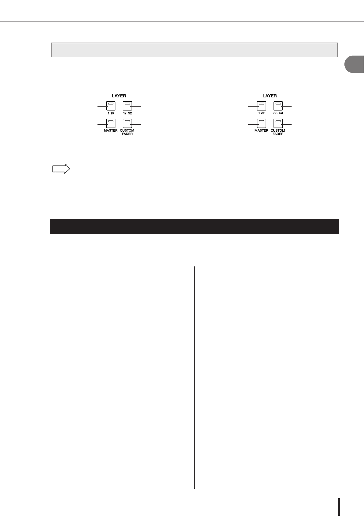
LAYER [1-32] key LAYER [33-64] key
LAYER [MASTER] key LAYER [CUSTOM
FADER] key
Differences between the LS9-16 and LS9-32 • The LS9’s channel structure
The names of the LAYER section keys differ between the LS9-16 and LS9-32.
● LS9-16 ● LS9-32
LAYER [1-16] key LAYER [17-32] key
LAYER [MASTER] key LAYER [CUSTOM
FADER] key
In conjunction with this difference, there are also differences in the numbering of the channel modules on the panel and the
channels that are assigned to each fader layer.
HINT
• In this owner’s manual, whenever there is a difference between the LS9-16 model and the LS9-32 model, specifications that apply only to the LS9-32 model are enclosed in curly brackets { } (e.g., INPUT jacks 1–16 {1–32}).
• When the specifications are common to both models, the manual refers simply to the LS9.
The LS9’s channel structure
1
Introduction
The LS9 provides the following input channels and output channels.
■ Input channels • • • • • • • • • • • • • • • • •
This section processes input signals and sends them to
various buses (STEREO, MONO, MIX). The LS9 has the
following two types of input channel.
● INPUT channels 1–32 {1–64}
These channels process monaural signals. In the initial
state, the input signals from the rear panel INPUT jacks
and the input channels of the slot(s) are assigned to these
channels.
● ST IN channels 1–4
These channels process stereo signals. In the initial state,
the outputs of virtual racks 5–8 are assigned to these channels.
Signal assignments to the input channels (input patching)
can be changed as desired.
■ Output channels • • • • • • • • • • • • • • • •
This section mixes the signals sent from input channels
etc., and sends them to the corresponding output ports or
output buses.
There are three types of output channel, as follows.
● MIX channels 1–16
These channels process the signals sent from input channels to the MIX buses, and send them from the output
ports. These are used mainly to send signals to the monitor
system or to external effects.
The signals of MIX channels 1–16 can also be sent to the
STEREO bus, MONO bus, or MATRIX buses.
When the LS9 is in the initial state, these are assigned to
the OMNI OUT jacks or the output channels of the slot(s).
● MATRIX channels 1–8
These channels process the signals that are sent from MIX
channels, STEREO channels, and MONO channel to the
MATRIX buses, and send them from the output ports.
Using the STEREO and MONO buses, different combinations of signals and mix balances can be sent out from the
console.
● STEREO channel / MONO channel
These channels process the signals that are sent from the
input channels or MIX channels, and send them to the corresponding output port. These channels are used as the
main stereo output and monaural output.
The STEREO channel and MONO channel can be used
either to output independent signals, or for three-channel L/
C/R playback.
When the
assigned to OMNI OUT jacks 15/16 {31/32} and to the
2TR OUT DIGITAL jack.
Signal assignments to the output channels (output patching) can be changed as desired.
LS9
is in the initial state, the STEREO channel is
LS9-16/32 Owner’s Manual
13
Page 14

About the MIX bus types (VARI / FIXED) • About word clock • Conventions in this manual • About the firmware version
About the MIX bus types (VARI / FIXED)
The sixteen MIX buses provided on the LS9 can be assigned either as VARI or FIXED types in
pairs of adjacent odd-numbered/even-numbered buses (→ p. 213). They can also be switched
between monaural/stereo for the same pairs of buses. VARI type and FIXED type buses differ as
follows.
● VARI
This type allows the send level of the signal sent from the
input channels to the MIX bus to be varied. The point at
which the signal is sent from the input channel to a VARI
type MIX bus can be chosen from before the EQ
(attenuator), before the fader, or after the [ON] key.
This type is used mainly for sending the signal to a monitor system or external effect.
● FIXED
With this type, the send level of the signal sent from the
input channels to the MIX bus is fixed. The signal from an
input channel is sent to a FIXED type MIX bus from
before Pan (if the MIX bus is monaural) or after Pan (if
the MIX bus is stereo). This type is used mainly when you
want to distribute signals to an external device with the
same mix as the STEREO/MONO buses.
About word clock
“Word clock” refers to the clock that provides the basis of timing for digital audio signal processing.
Normally, one device transmits a reference word clock signal, and the other devices receive this
word clock signal and synchronize to it.
In order to transmit or receive digital audio signals to or from an external device via the LS9’s
2TR IN DIGITAL/2TR OUT DIGITAL jacks or via a digital I/O card installed in a slot, the word
clock must be synchronized between the devices. Be aware that if the word clock is not synchronized, the signal will not be sent correctly, or there may be unpleasant noise. (For details on synchronizing the LS9’s word clock with an external device → p. 46)
Conventions in this manual
In this manual, switch-type controllers on the panel are called “keys.” Of the control knobs on the
panel, those that turn from a minimum value to a maximum value are called “controls,” while
those that turn endlessly are called “encoders.”
Controllers located on the panel are enclosed in square
brackets [ ] (e.g., [CUE] key) in order to distinguish them
from the virtual buttons and knobs displayed in the screen.
For some controllers, the name of the section is given
before the [ ] (e.g., LAYER [MASTER] key).
Whenever there is a difference between the LS9-16 model
and the LS9-32 model, specifications that apply only to
the LS9-32 model are enclosed in curly brackets { } (e.g.,
INPUT jacks 1–16 {1–32}).
About the firmware version
You can view the firmware version number in the MISC SETUP screen (→ p. 206).
You can also download the most recent firmware version from the website.
http://www.yamahaproaudio.com/
LS9-16/32 Owner’s Manual
14
Page 15

Chapter 2
Parts and their function
This chapter explains the LS9’s parts and their functions.
Top panel
2
The LS9’s top panel is organized into the following sections.
LS9-16
m MIX/MATRIX SELECT section (p. 20)
b DISPLAY ACCESS section (p. 19)
n LAYER section (p. 19)
, Display (p. 20)
. Stereo meter / Cue section (p. 20)
⁄0 SELECTED CHANNEL section (p. 21)
Parts and their function
⁄2 USB connector (side
panel, to the right of the
display) (p. 22)
⁄1 Data entry section
(p. 22)
z Channel module section (p. 17) c STEREO MASTER section (p. 18)
v USER DEFINED KEYS section (p. 18)
x ST IN (stereo input)
section (p. 17)
LS9-16/32 Owner’s Manual
15
Page 16

Top panel
LS9-32
m MIX/MATRIX SELECT section (p. 20)
b DISPLAY ACCESS section (p. 19)
n LAYER section (p. 19)
⁄0 SELECTED CHANNEL section (p. 21)
. Stereo meter / Cue section (p. 20)
, Display (p. 20)
⁄1 Data entry section
(p. 22)
⁄2 USB connector
(side panel, to the
right of the display)
(p. 22)
z Channel module section (p. 17) c STEREO MASTER section (p. 18)
LS9-16/32 Owner’s Manual
16
v USER DEFINED KEYS section (p. 18)
x ST IN (stereo input) section (p. 17)
Page 17
Top panel
1
2
4
5
3
1
2
4
5
3
LS9-32LS9-16
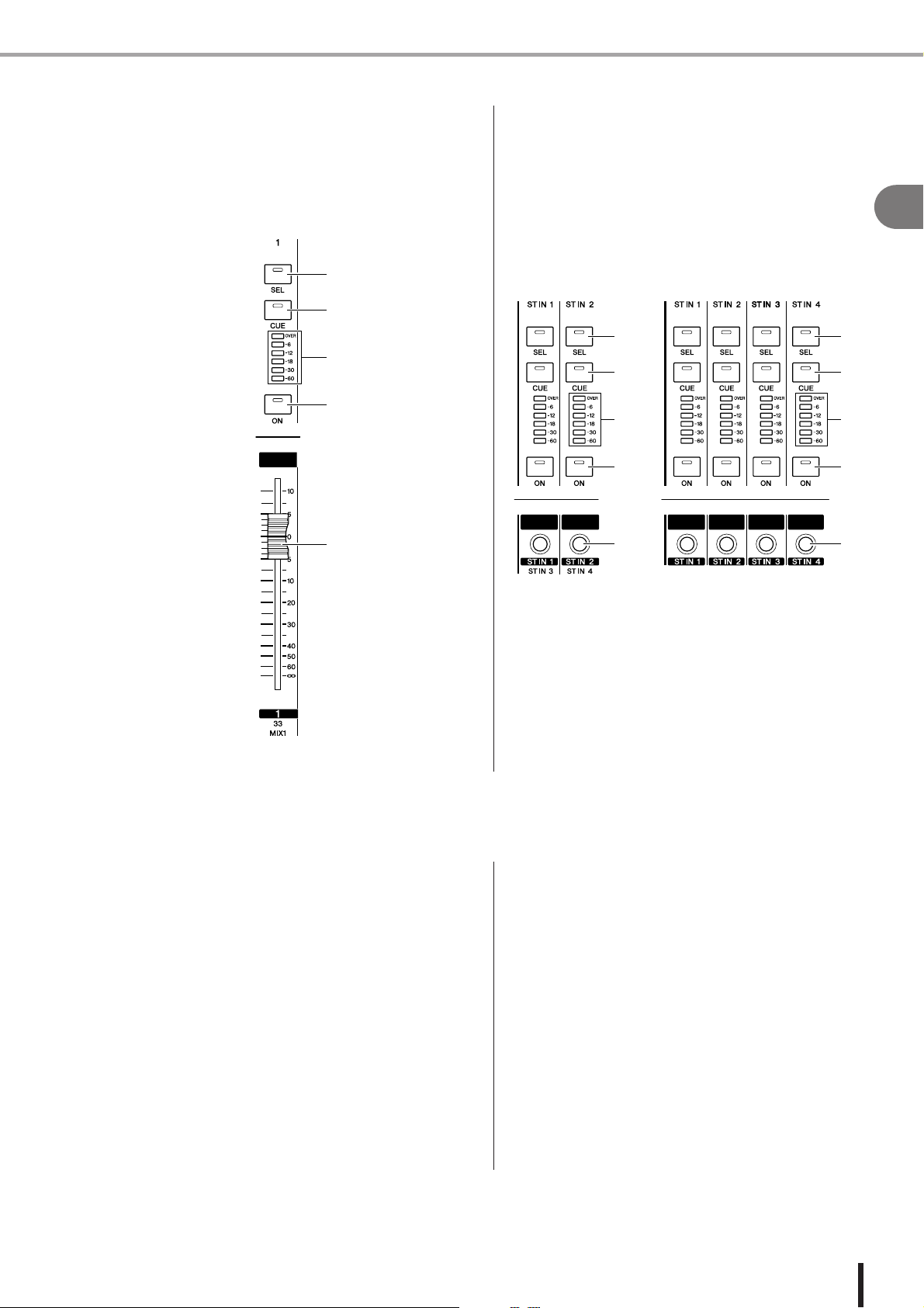
z Channel module section• • • • • • • • • • •
In this section you can operate the main parameters of the
input channels and output channels, as well as the monitor
output. Use the LAYER section (→ p. 19) to select the
channels that are mapped to this section.
1
2
3
4
5
x ST IN (stereo input) section • • • • • • • •
In this section you can operate the main parameters of the
stereo ST IN channels 1–4. The function of each controller is the same as in the Channel Module section, with the
exception that the L-channel or R-channel will be alternately selected as the target of operations each time you
press the [SEL] key, and the fact that the encoder rather
than the fader is used to adjust the level.
2
Parts and their function
1 [SEL] key
This key selects the channel to be operated. When you
press this key to make the LED light, the corresponding
channel will be selected for operations in the SELECTED
CHANNEL section or in the display. In the ST IN section,
the L-channel and R-channel will be alternately selected
as the target of operations each time you press the [SEL]
key.
B [CUE] key
This key selects the channel to be cue-monitored. When
cue is on, the LED will be lit.
C Meter LEDs
These LEDs indicate the audio signal level of the input
channel or output channel.
D [ON] key
This switches the channel on/off. The key LED will light
for channels that are on. In SENDS ON FADER mode,
this key is an on/off switch for the signal that is sent from
that channel to the currently selected MIX bus (or from a
MIX channel, to the MATRIX bus).
E Fader/Encoder
This adjusts the signal level or monitor level of the input
channel or output channel. In SENDS ON FADER mode,
this adjusts the send level from that channel to the currently selected MIX bus (or from a MIX channel, to the
MATRIX bus).
LS9-16/32 Owner’s Manual
17
Page 18

Top panel
c STEREO MASTER section • • • • • • • • • • •
In this section you can operate the main parameters of the
STEREO channel.
1
2
3
4
v USER DEFINED KEYS section• • • • • • • • •
Here you can execute the functions that are programmed
for the user-defined keys.
1
1 User-defined keys [1]–[12]
These keys execute the functions that have been programmed for each key (e.g., switching scenes, turning
talkback or the internal oscillator on/off).
1 [SEL] key
This key selects the STEREO channel as the target of
operations. The L-channel and R-channel will be alternately selected as the target of operations each time you
press the [SEL] key.
B [CUE] key
This key cue-monitors the STEREO channel. When cue is
on, the LED will be lit.
C [ON] key
This switches the STEREO channel on/off. When on, the
key LED will light. In SENDS ON FADER mode, you can
use this as an on/off switch for MIX/MATRIX channels or
as an on/off switch for the signal sent from the STEREO
channel to the MATRIX buses, depending on the LAYER.
D Fader
This adjusts the output level of the STEREO channel. In
SENDS ON FADER mode, this adjusts the level of the
MIX/MATRIX channels or the send level from the STEREO channel to the MATRIX buses, depending on the
LAYER.
HINT
• If you turn on MONITOR ON MASTER FADER in the USER
DEFINED KEY SETUP screen, the [ON] key and fader will respectively turn MONITOR on/off and control its level.
LS9-16/32 Owner’s Manual
18
Page 19

Top panel
2
43
1 2
43
1
LS9-16 LS9-32
b DISPLAY ACCESS section • • • • • • • • • • • • • • • • • • • • • • • • • • • • • • • • • • • • • • • • • • • •
D [CHANNEL JOB] key
This key accesses a screen where you can make settings
1
3
5
2
4
6
87
for Channel Link, Mute Group, and Recall Safe functions,
and copy or move settings between channels.
E [RECORDER] key
This key accesses a screen where you can operate and
make settings for the Recorder function which records and
plays audio files.
F [METER] key
This key accesses a meter screen where you can view the
input/output levels of all channels in a single view.
2
G [RACK 1-4] key
This key accesses a screen where you can edit the graphic
1
[SCENE MEMORY] key
This key accesses a screen where you can store, recall, and
edit scene memories, and make settings for the Focus
function and Fade Time function.
EQ assigned to virtual racks 1–4. By pressing the [RACK
1-4] key and [RACK 5-8] key simultaneously you can
access the VIRTUAL RACK screen, where you can assign
a graphic EQ (31 Band GEQ or Flex 15 GEQ) to each virtual rack.
B [MONITOR] key
This key accesses a screen where you can make settings
for cue, monitor, oscillator, and talkback.
H [RACK 5-8] key
This key accesses a screen where you can edit the graphic
EQ or internal effect that is assigned to virtual racks 5–8,
C [SETUP] key
This key accesses a screen where you can set and verify
the user level, and make basic system settings.
and make settings for external head amps. By pressing the
[RACK 1-4] key and [RACK 5-8] key simultaneously you
can access the VIRTUAL RACK screen, where you can
assign a graphic EQ (31 Band GEQ or Flex 15 GEQ) or
internal effect to each virtual rack.
n LAYER section • • • • • • • • • • • • • • • • • • • • • • • • • • • • • • • • • • • • • • • • • • • • • • • • • • •
Here you can select the type of channels that will be operated from the channel module section (→ p. 17) and ST IN section
(→ p. 17).
Parts and their function
1 LAYER [1-16] {LAYER [1-32]} key
B LAYER [17-32] {LAYER [33-64]} key
C LAYER [MASTER] key
These keys assign fixed preset combinations of channels to the channel module section and the ST IN
section. The combination of channels corresponding to each key is as follows.
For the LS9-16
LAYER key / module 1–16 ST IN 1–2
LAYER [1-16] key CH 1–16 ST IN 1–2
LAYER [17-32] key CH 17–32 ST IN 3–4
LAYER [MASTER] key MIX 1–16 —
For the LS9-32
LAYER key / module 1–16 17–24 25–31 32 ST IN 1–4
LAYER [1-32] key CH 1–16 CH 17–24 CH 25–31 CH 32 ST IN 1–4
LAYER [33-64] key CH 33–48 CH 49–56 CH 57–63 CH 64 ST IN 1–4
LAYER [MASTER] key MIX 1–16 MATRIX 1–8 — MONO —
D LAYER [CUSTOM FADER] key
This key assigns the channels selected by you (the user) to the channel module section and the ST IN
section. (For the channel assignment procedure → p. 91)
LS9-16/32 Owner’s Manual
19
Page 20

Top panel
m MIX/MATRIX SELECT section • • • • • • • • •
In this section you can select the MIX channel or
MATRIX channel that will be the object of operations.
1
1 MIX/MATRIX [1]–[16] keys
These keys select the MIX channel (or if the selected
channel is a MIX/STEREO/MONO channel, the
MATRIX channel) whose send level will be adjusted by
the SELECTED CHANNEL section. The LED of the key
corresponding to the currently selected channel will light
(or blink, in the case of a MATRIX channel).
In SENDS ON FADER mode, these keys select a MIX bus
or MATRIX button as the send-destination. In this case,
the LED of the key corresponding to the currently selected
bus will blink, and the LED of keys corresponding to
selectable buses will light. For MATRIX buses, the [9]–
[16] keys will be dark and cannot be selected.
, Display • • • • • • • • • • • • • • • • • • • • • •
In this display you can view and edit all mix parameters,
as well as various settings.
Use the DISPLAY ACCESS section (→ p. 19) to select the
screen that you want to view. Then use the cursor keys of
the data entry section (→ p. 22) to move the cursor to the
desired parameter, and use the dial or the [INC][DEC]
keys to edit the value.
. Stereo meter / Cue section • • • • • • • •
In this section you can view the level of the STEREO
channel or cue monitor.
1
LS9-16/32 Owner’s Manual
20
2
3
1 Stereo meter
This is a 32-segment LED meter that indicates the L/R
channel levels of the STEREO channel.
While the [CUE] key of any channel is on, this meter will
indicate the cue monitor level.
B CUE LED
This LED will blink while the [CUE] key of any channel
is on.
C [CUE CLEAR] key
This key clears all cue monitoring that is currently active.
Page 21

Top panel
• In SENDS ON FADER mode, this encoder will not do anything regardless of which channel is selected.
• By simultaneously pressing the EQ [Q] encoder and the EQ
[GAIN] encoder, you can reset the gain to 0 dB for the band
selected by the keys below (
9–L
).
• If you have selected a LOW band or HIGH band whose type can
be changed, you can switch the type by turning the EQ [Q]
encoder while pressing it when Q is set to the maximum or minimum value.
LOW band :
• Switches to LOW shelving if you turn the encoder toward the
right while pressing it when Q is at the minimum value
• Switches to high pass filter if you turn the encoder toward the
left while pressing it when Q is at the maximum value (MIX,
MATRIX, STEREO, and MONO channels only)
HIGH band :
• Switches to HIGH shelving if you turn the encoder toward the
right while pressing it when Q is at the minimum value
• Switches to low pass filter if you turn the encoder toward the
left while pressing it when Q is at the maximum value
For shelving, high pass filter, and low pass filter as well, you can
switch the type by turning the encoder while pressing it.
⁄0 SELECTED CHANNEL section• • • • • • • • •
In this section you can operate the most important mix
parameters for the currently selected input channel or output channel.
The function of the controllers in this section will depend
on the type of channel that is selected.
1
4
2
3
6
7
8
M
1 [HA GAIN] encoder
● When an INPUT/ST IN channel is selected
The encoder will adjust the gain of the internal head
amp or an external head amp device (AD8HR) connected to a rear panel slot.
NOTE
• The PAD will be internally switched on or off when the HA
gain is adjusted between -14 dB and -13 dB. Keep in mind
that noise may be generated if there is a difference between
the Hot and Cold output impedance of the external device
connected to the INPUT connector when using phantom
power.
● When any other channel is selected
The encoder will not do anything.
5
9
J
K
L
C [SELECTED SEND] encoder
● When an INPUT/ST IN channel is selected
The encoder will adjust the send level from that channel to the currently selected bus. (For a FIXED type
bus, the encoder will switch the send on/off.)
If the send-destination bus is stereo, this encoder will
specify the panning of the signal sent to the two buses
if an odd-numbered bus is selected, or will specify the
send level if an even-numbered bus is selected.
● When a MIX channel is selected
The encoder will adjust the send level from that MIX
channel to the currently selected MATRIX bus.
● When a MATRIX channel is selected
The encoder will adjust the send level from the MIX
channels to the currently selected MATRIX bus.
NOTE
D [DYNAMICS 1] encoder
● When an INPUT/ST IN channel is selected
The encoder will adjust the threshold of Dynamics 1
(e.g., gate).
● When any other channel is selected
The encoder will adjust the threshold of the compressor, etc.
E [DYNAMICS 2] encoder
● When an INPUT/ST IN channel is selected
The encoder will adjust the threshold of Dynamics 2
(e.g., compressor).
● When any other channel is selected
The encoder will not do anything.
F EQ [Q] encoder
G EQ [FREQUENCY] encoder
H EQ [GAIN] encoder
These encoders adjust the Q, frequency, and gain of the
band selected by keys 9–L.
HINT
2
Parts and their function
B [PAN] encoder
● When an INPUT/ST IN channel is selected
● When a MIX channel is selected
The encoder will adjust the panning of the signal sent
to the L/R channels (or the L/C/R channels in the case
of LCR mode) of the STEREO bus. If a MIX channel
set to stereo is selected, the encoder will adjust the
output balance of the left and right channels.
● When a MATRIX channel is selected
If a monaural MATRIX channel is selected, the
encoder will not do anything. If a stereo MATRIX
channel is selected, the encoder will adjust the output
balance of the left and right channels.
● When a STEREO/MONO (C) channel is
selected
The encoder will not do anything for MONO (C)
channel. For a STEREO channel, the encoder will
adjust the output balance of the left and right channels.
LS9-16/32 Owner’s Manual
21
Page 22

Top panel
I EQ [HIGH] key
J EQ [HIGH MID] key
K EQ [LOW MID] key
L EQ [LOW] key
These keys select the band controlled by encoders 6–8.
By simultaneously pressing the EQ [HIGH] key and EQ
[LOW] key, you can reset the gain of all four bands to 0
dB.
M [HOME] key
This key returns the state of the LS9’s panel to home position. When you press this key, the panel will change as follows.
• The display will show the SELECTED CH VIEW
screen for the currently selected channel.
• The channel level function will be assigned to the faders (SENDS ON FADER mode will be defeated).
⁄1 Data entry section • • • • • • • • • • • • • • •
This section lets you edit specific parameters in the screen.
1
⁄2 USB connector (side panel, to the right
of the display)
This connector lets you connect USB memory.
1 USB connector
USB memory can be connected here, and used to save or
load internal data. User authentication key data to define
the user level can also be saved on USB memory and used
to restrict the functionality that is available to each user.
NOTE
• Operation is guaranteed only for USB flash memory.
• • • • • • • • • • • • • • • • •
1
2
3
4
1 [DEC]/[INC] keys
These keys increment or decrement the value of the
parameter at which the cursor is located in the screen, in
steps of -1/+1.
B Cursor keys
These keys move the cursor up/down/left/right in the
screen.
C Dial
This dial continuously increments or decrements the value
of the parameter at which the cursor is located in the
screen.
■ USB memory format
Only USB memory that is 2 GB or less in capacity
and is formatted in FAT12, FAT16, or FAT32 is supported. If the USB memory is formatted in any
other way, you must reformat it in the USER SETUP
screen.
■ Write protection
Some USB memory has write protection that prevents
data from being erased inadvertently. If your USB memory
contains important data, we suggest that you use its write
protect feature to prevent accidental erasure.
Conversely, you must make sure that your USB memory’s
write protect feature is disabled before you attempt to
save data to it.
CAUTION
• The ACCESS indicator will appear in the upper part of the
screen while data is being accessed, such as during saving,
loading, or deleting. During this time, you must not disconnect the USB memory from the USB connector or power-off
the LS9. Doing so may damage your USB memory, or damage
the data in the LS9 or in the USB memory.
D [ENTER] key
This key is used to switch a button in the screen on/off, or
to confirm a change you make.
LS9-16/32 Owner’s Manual
22
Page 23

Rear panel
1 32
4 5 6 7 8
K JL M
14JK 5 6 7 8 9
2L M 3
Rear panel
LS9-16
LS9-32
2
Parts and their function
LS9-16/32 Owner’s Manual
23
Page 24

Rear panel
1 INPUT jacks 1–16 {1–32}
LS9-16
LS9-32
These are balanced XLR-3-31 female input jacks for inputting analog
audio signals from line level devices or microphones. The nominal
input level is -62 dBu – +10 dBu. Resettable head amps are provided
on all jacks, and head amp settings can be stored in scene memory.
B OMNI OUT jacks 1–8 {1–16}
LS9-16
LS9-32
These are XLR-3-32 male output jacks for outputting analog audio signals. These are used mainly to output MIX/
MATRIX channel signals. The nominal output level is +4
dBu.
C Slots {1–2}
Separately sold mini-YGDAI I/O cards can be installed in
these slots to provide additional input/output ports. The
LS9-16 has one slot, and the LS9-32 has two slots. Each
slot can input/output a maximum of 16 channels of signals.
Male XLR plug
LS9-16
LS9-32
1 (ground)
3 (cold)
2 (hot)
Female XLR plug
NOTE
• The nominal output level of OMNI OUT jacks 1–8 {1–16} is +4 dBu
(maximum level is +24 dBu), but if necessary this can be changed
by an internal switch to -2 dBu (maximum level is +18 dBu). (A fee
will be charged for this change.) For details, contact to your
Yamaha dealer listed at the end of this manual.
LS9-16/32 Owner’s Manual
24
2 (hot)
3 (cold)
1 (ground)
Page 25

4 5 6 7 8
JKML
L
M
K
J
LS9-16
LS9-32
Rear panel
LS9-16
4 5 6 7 8 9
LS9-32
D NETWORK connector
This connector allows the LS9 to be connected to a Windows computer via a CAT3 (transfer rate: maximum 10
Mbps) or CAT5 (transfer rate: maximum 100 Mbps) compatible Ethernet cable. This is used mainly for controlling
mix parameters or editing scene memories and libraries
from the dedicated “LS9 Editor” application program.
NOTE
• The DME-N Network Driver required for connection to the NETWORK connector, the Studio Manager required for running LS9
Editor, and the LS9 Editor itself can downloaded from the Yamaha
website listed below.
http://www.yamahaproaudio.com/
E WORD CLOCK IN/OUT connectors
These are BNC connectors used to transmit and receive
word clock signals to and from an external device. The
WORD CLOCK IN connector is internally terminated by
a 75 ohm resistor.
F 2TR OUT DIGITAL jack
This is a coaxial jack that outputs the digital audio signal
of a specified channel in consumer format (IEC-60958).
This is used mainly to output STEREO/MONO channel
signals.
G 2TR IN DIGITAL jack
This is a coaxial jack that inputs a stereo digital audio signal in consumer format (IEC-60958). The signal input
from this jack can be patched to any input channel.
2
Parts and their function
J AC IN connector
Connect the included power cable to this connector to supply power to the unit.
K POWER switch
This switch turns the power on/off.
L Grounding screw
To ensure safe operation, be sure to ground the LS9
securely. The included power cable has a three-conductor
plug, so if the AC outlet is grounded the LS9 will be
grounded appropriately. If the AC outlet is not grounded,
establish a secure ground connection from this screw. Correctly grounding the unit is an effective way to eliminate
hum and interference noise.
M Cooling fan vent
This is the vent for the cooling fan inside the console.
When placing the console, be careful not to block this
vent.
H MIDI IN/OUT connectors
These connectors are used to transmit and receive MIDI
messages to and from external MIDI devices. The MIDI
IN connector receives messages from an external device,
and the MIDI OUT connector transmits messages from
the LS9. These are used mainly for recording LS9 parameter operations or scene/library changes on an external
device, or for remotely operating LS9 parameters.
I LAMP connector (LS9-32 only)
This is an XLR-4-31 connector that supplies power to a
separately sold gooseneck lamp (e.g., Yamaha LA5000).
The brightness of the lamp can be adjusted in the screen.
LS9-16/32 Owner’s Manual
25
Page 26

Front panel
Front panel
1 2
1 PHONES LEVEL control
This adjusts the level of the signal that is output from the
PHONES OUT jack 2.
B PHONES OUT (headphone output) jack
This is a headphone jack for monitoring the MONITOR
OUT or CUE signal.
LS9-16/32 Owner’s Manual
26
Page 27

Chapter 3
LS9-16 LS9-32
Basic operations on the LS9
This chapter explains the various user interfaces you’ll use to operate the
LS9, and basic operations.
Basic operations in the top panel
Here we explain basic operations you’ll perform in the LS9’s top panel.
3
About the [HOME] key Selecting the fader layer
The [HOME] key in the SELECTED CHANNEL section
restores the LS9’s panel to its basic state (home position).
When you press the [HOME] key, the panel will change as
follows.
• The display will show the SELECTED CH VIEW
screen, where you can view all parameters of the
selected channel.
The channel module section of the top panel lets you
switch between combinations of channels to be controlled
(“fader layers”) so that you can control input channels,
output channels, or monitor levels.
Press the keys of the LAYER section to switch the combination of channels you want to control.
Basic operations on the LS9
• The channel level function will be assigned to the faders (SENDS ON FADER mode will be defeated).
The [HOME] key will blink if the display is showing any
screen other than the SELECTED CH VIEW screen, or if
SENDS ON FADER mode is active. In such cases, you
will find it convenient to press the [HOME] key to restore
the panel to home position (the [HOME] key will change
to steadily lit), and then proceed with operations.
LS9-16/32 Owner’s Manual
27
Page 28

Basic operations in the top panel
The combination of channels corresponding to each key is as follows.
LS9-16
LAYER section key
LAYER [1-16]
LAYER [17-32]
LAYER [MASTER]
LAYER [CUSTOM FADER]
LS9-32
INPUT CH 1–16
INPUT CH 17–32
MIX 1–16
Any desired channels
STEREO ST IN 1–2
ST IN 3–4STEREO
STEREO
STEREO Any desired channels
—
LAYER section key
LAYER [1-32]
LAYER [33-64]
LAYER [MASTER]
LAYER [CUSTOM FADER]
HINT
• On the LS9-16, MATRIX channels and MONO channels are not assigned to the fader layers that are preset.
If you want to use the top panel faders and [ON] keys to control the MATRIX channels or MONO channel,
you can assign them to the custom fader layer (
LS9-16/32 Owner’s Manual
28
INPUT CH 1–16
INPUT CH 33–48
MIX 1–16
→
p. 91).
MATRIX 1–8
Any desired channels
INPUT CH 17–32 STEREO ST IN 1–4
INPUT CH 49–64
——
STEREO
MONO
STEREO Any desired channels
ST IN 1–4STEREO
Page 29

Basic operations in the top panel
• If you press the lit DISPLAY ACCESS key while a popup
screen is displayed, the popup screen will close.
• If you press and hold down the DISPLAY ACCESS section
key, the previously displayed screen will appear.
Using the SELECTED CHANNEL section
You can use the encoders and keys of the SELECTED
CHANNEL section to directly operate the mix parameters
(EQ, pan, dynamics, etc.) of the currently selected channel
from the top panel.
Selecting functions
Use the keys of the DISPLAY ACCESS section when you
want to use functions other than mix parameters, or when
you want to change various settings.
3
Basic operations on the LS9
When you press one of the keys in the DISPLAY
ACCESS section, the corresponding screen will appear in
the display. If the screen consists of more than one page,
you can switch between pages by pressing the same key
repeatedly. For example if you press the [SCENE MEMORY] key, the SCENE MEMORY screen will appear,
where you can store or recall scene memories.
Make sure that the desired fader layer is
1
selected in the LAYER section.
Use the [SEL] keys of the channel module
2
section, STEREO section, and ST IN section
to select the channel that you want to operate.
The currently selected channel is indicated in the
upper left of the screen.
For stereo channels (STEREO channels, ST IN channels), you will alternate between the L-channel and Rchannel each time you press the [SEL] key.
HINT
• If AUTO CHANNEL SELECT is turned on in the PREFERENCE popup window (
simply by operating its [ON] key or fader, without having to
press its [SEL] key.
Turn the encoders of the SELECTED CHAN-
3
→
p. 194), you can select a channel
NEL section to edit the desired parameters.
The parameter assigned to each encoder will change.
Before operating the EQ encoders, you’ll need to use
the EQ [HIGH], EQ [HIGH MID], EQ [LOW MID],
and EQ [LOW] keys to select the band you want to
control.
HINT
HINT
• By pressing one of the SELECTED CHANNEL section’s
encoders inward, you can also access a popup window where
you can edit detailed settings for the parameter (
→
p. 194).
LS9-16/32 Owner’s Manual
29
Page 30

Viewing the display
Viewing the display
Here we explain the various types of information shown in the display.
D User name / status
Constant display area
12 5
This shows the name of the user who is currently loggedin (authenticated and permitted to operate the console).
Other indicators are shown here if oscillator or talkback is
on, or if internal memory or USB memory is being
accessed.
3
4
1 Selected channel
This shows the number, name, and icon of the channel
currently selected by its [SEL] key for operations. (For
details on assigning a name → p. 34, For details on selecting an icon → p. 55, 69) You can also move the cursor to
this area and use the dial or the [DEC]/[INC] keys to
change the selected channel.
B Scene memory
This shows the number and name of the scene that is currently selected for store/recall operations.
An “R” (Read Only) indication is shown for read-only
scenes or write-protected scenes. If you have modified the
parameters from their most recently stored or recalled
state, an “E” (Edited) indication is shown. Move the cursor to the scene number, use the dial or the [DEC]/[INC]
keys to change the scene number, and press the [ENTER]
key to recall the scene.
NOTE
• Simply changing the scene that is shown here will not execute a
store/recall operation.
•To execute a store or recall operation, access the SCENE MEMORY screen and use the STORE/RECALL buttons in the screen
→
p. 129), or press a user-defined key to which you’ve assigned
(
the scene store/recall operation (
•You can also move the cursor to the scene number in the constant
display area and use the dial or the [DEC]/[INC] keys to change
the scene number. This scene number will blink if the most
recently stored or recalled scene is different than the currently
selected scene.
→
p. 132).
When oscillator is on
When talkback is on
While recording to USB memory
While playing from USB memory
While accessing internal memory when storing
USB memory or a scene
E ST IN level
This indicates the on/off status and input level of ST IN
channels 1–4. This shows a gray knob and black index
when on, or a dark gray knob and black index when off.
In SENDS ON FADER mode, this shows the on/off status
and send level of the signal sent from ST IN channels 1–4
to the MIX bus. When on, the knob will be a color corresponding to the send-destination (the same type of color
as the keys of the MIX/MATRIX SELECT section), and
the indices will be white. When off, the knob will be gray
and the indices will be black.
HINT
• In SENDS ON FADER mode, the send-destination bus is shown
blinking at the right of the scene number.
C MIDI
The MIDI indicator will appear when MIDI messages are
received.
LS9-16/32 Owner’s Manual
30
Page 31

Main area
Popup window
The contents of the main area will depend on the currently
selected function.
■ SELECTED CH VIEW screen
This screen shows all mix parameters of the currently
selected channel. To access this screen, press the [HOME]
key of the SELECTED CHANNEL section.
Viewing the display
■ Popup windows
Some windows show lists or details of specific parameters
in the screen. These are called “popup windows.”
3
■ Various function screens
These screens allow you to access functions and settings
other than channel mix parameters. To access each of
these screens, press the appropriate key of the DISPLAY
ACCESS section.
By operating the knobs and buttons in a popup window,
you can edit more detailed parameters. In some popup
windows, there are several buttons called “tool buttons” in
the upper part of the window. You can use these tool buttons to recall or copy/paste library data.
To close the popup window and return to the previous
screen, move the cursor to the “×” symbol or the CLOSE
button, and press the [ENTER] key. (You can also close
the popup window and return to the SELECTED CHANNEL VIEW screen by pressing the [HOME] key.)
Basic operations on the LS9
LS9-16/32 Owner’s Manual
31
Page 32

Viewing the display
The on-screen user interface
The interface shown in the screen of the LS9 includes the
following items.
■ Cursor
The blinking red and yellow frame displayed in the screen
is called the “cursor.”
The cursor is used to specify the object of your operations.
Use the cursor keys of the data entry section to move the
cursor up/down/left/right.
Cursor
■ Knobs and faders
Knobs in the screen are used to view or edit the values of
the corresponding parameters. Normally, you will move
the cursor to a knob and use the dial or [DEC]/[INC] keys
of the data entry section to edit the value. The current
value is shown in numerical form immediately below the
knob. Some knobs will move in tandem with the encoders
of the SELECTED CHANNEL section.
Knob
Faders in the screen are mainly used to view or edit the
level of the corresponding channels. They will move in
tandem with the faders of the top panel. You can also
move the cursor to a fader and use the dial or [DEC]/
[INC] keys of the data entry section to edit the value. The
current value is shown in numerical form immediately
below the fader.
■ Buttons
Buttons in the screen are used to execute specific functions, to switch parameters on/off, or to select one of several choices.
To execute a button’s function, to switch it on/off, or to
select a desired item, move the cursor to the desired button
and press the [ENTER] key of the data entry section.
By moving the cursor to a button that shows the ▼ symbol
and then pressing the [Enter] key, you can open another
popup window where you can specify details.
Buttons
Fader
■ List window
A window like the following will appear when you are
selecting an item from a list, such as when selecting a
function for a user-defined key.
Within the list, the constantly-highlighted item in the center is the selected item. To scroll the list up or down, use
the dial or the [DEC]/[INC] keys.
List window
LS9-16/32 Owner’s Manual
32
Page 33

Viewing the display
■ Keyboard window
The keyboard window shown below will appear when you
assign a name or comment to a scene or library, or when
you assign a name to a channel. To enter characters, move
the cursor to the desired character in the window and press
the [ENTER] key. (For the procedure → p. 34)
Keyboard window
■ Dialog box
When you need to confirm the operation you just performed or when a problem has occurred, a dialog box will
appear, asking you to confirm the operation or displaying
a warning.
● CONFIRMATION dialog box
This dialog box will appear when confirmation is
required. Move the cursor to the OK button to execute
the operation (or to the CANCEL button to cancel it),
and press the [ENTER] key.
● CAUTION dialog box
This dialog box will display a warning if a fatal error
has occurred in the operation you attempted to execute. When you move the cursor to the CLOSE button
and press the [ENTER] key, the operation will be forcibly cancelled, and the dialog box will disappear.
3
Basic operations on the LS9
● ATTENTION dialog box
This dialog box will display a warning when a problem has occurred with the operation you are attempting to execute.
If you move the cursor to the OK button and press the
[ENTER] key, the operation will be executed in a way
that circumvents the problem. If you move the cursor
to the CANCEL button and press the [ENTER] key,
the operation will be cancelled.
LS9-16/32 Owner’s Manual
33
Page 34

Assigning a name
Assigning a name
On the LS9, you can assign a name to each input channel and output channel, and assign a title
to each scene or library data item when you save it.
To assign a name, you will use the keyboard window that is shown in the main area.
Access the window where you can assign a
1
name.
The illustration below shows the SCENE STORE
popup window that is used when assigning a name to a
scene.
Text input box
A yellow vertical line called the “text cursor” is shown
to indicate the current location in the box that displays
the characters that have been input.
Use the on-screen keyboard to enter text.
2
Move the cursor (the red frame) to the desired character in the keyboard window and press the [ENTER]
key; the character will be entered in the text input box,
and the text cursor (yellow vertical line) in the box will
move to the right.
● DEL button
Deletes the character to the right of the text cursor.
● BS button
Deletes the character to the left of the text cursor.
● SHIFT LOCK button
Switches between uppercase and lowercase alphabetical characters. You’ll be able to enter uppercase characters and symbols if this button is on, and lowercase
characters and numerals if this button is off.
● ENTER button
Finalizes the name you entered. In the SCENE
STORE popup window, you can obtain the same result
by moving the cursor to the STORE button and pressing the [ENTER] key.
When you’ve entered the name, move the
4
cursor to the STORE button or the ENTER
button and press the [ENTER] key.
The name you entered will be applied.
HINT
• The basic procedure is the same in the windows that let you
assign names to channels or other types of library data. If
you’re entering a channel name, the name will be updated
immediately, without your having to use the ENTER button.
Enter the subsequent characters in the
3
same way.
While entering characters, you can use the following
buttons in the keyboard window.
● COPY button
Copies the entire text string from the text box into
buffer memory.
● PASTE button
Inserts the text string copied using the COPY button at
the location of the text cursor.
● CLEAR button
Erases all characters that were entered in the text input
box.
←←
● ←←
/ →→→→ buttons
Moves the text cursor forward or backward in the text
input box.
● INS button
Inserts a space (blank) at the text cursor.
LS9-16/32 Owner’s Manual
34
Page 35

Using the tool buttons
Using the tool buttons
The title bar at the top of some popup windows and screens contains tool buttons that provide
additional functions. You can use these buttons to recall related libraries, or to copy the parameters of a channel to a different channel. Here we will explain how to use the tool buttons.
About the tool buttons
Using libraries
3
Tool buttons like the following are shown in the ATT/
HPF/EQ, DYNAMICS 1/2, GEQ, and EFFECT popup
windows and screens.
12 345
1 LIB (library) button
This button recalls the library that is related to the current
popup window or screen (EQ, dynamics, GEQ, or effect
library).
B DEF (default) button
This button restores the currently selected channel (EQ/
dynamics) or rack (effect) to the default state.
C COPY button
This button copies the settings of the currently selected
channel (EQ/dynamics) or rack (GEQ/effect). The copied
settings are held in buffer memory (a memory area for
temporary storage).
D PASTE button
This button pastes the settings held in buffer memory into
the currently selected channel (EQ/dynamics) or rack
(GEQ/effect).
Here we will explain the basic procedure for using libraries. You can use libraries to store (save) or recall (load)
the settings of the currently selected channel (EQ/dynamics) or rack (GEQ/effect).
The following libraries are provided.
• Input EQ library
• Output EQ library
• Dynamics library
• GEQ library
•Effect library
The operating procedure is essentially the same for all
libraries.
● Recalling data from a library
Access a popup window or screen that con-
1
tains tool buttons.
To access each popup window or screen, proceed as
follows.
[ ATT/HPF/EQ popup window ]
[ DYNAMICS 1/2 popup window ]
Basic operations on the LS9
E COMPARE button
This button exchanges the settings held in buffer memory
with the settings of the currently selected channel (EQ/
dynamics) or rack (GEQ/effect).
NOTE
•You cannot press the PASTE button or COMPARE button if no settings have been copied into buffer memory.
In addition, some screens have the following tool buttons.
• SET ALL ...............Turns on all of the parameters in the
screen.
• CLEAR ALL..........Turns off all of the parameters in the
screen.
LS9-16/32 Owner’s Manual
35
Page 36

Using the tool buttons
In the SELECTED CH VIEW screen, move the cursor
to the knob corresponding to EQ or dynamics 1/2, or
to a button that has a ▼ symbol, and press the
[ENTER] key.
HINT
• If POPUP APPEARS WHEN PRESSING KNOBS is turned
on in the PREFERENCE popup window (
access the popup window by pressing the SELECTED
CHANNEL section encoder that corresponds to EQ or
dynamics 1/2.
→
p. 194), you can
[ RACK screen ]
In the DISPLAY ACCESS section, press the [RACK
1-4] or [RACK 5-8] key.
[ RACK screen ]
In the DISPLAY ACCESS section, repeatedly press
the [RACK 1-4] or [RACK 5-8] key.
HINT
• If you want to change the assignment (31BandGEQ,
Flex15GEQ, or effect) to each rack, simultaneously press the
[RACK 1-4] key and [RACK 5-8] to access the VIRTUAL
RACK screen (
Move the cursor to the LIB button in the
3
→
p. 158).
toolbar and press the [ENTER] key to
access the popup window of the corresponding library.
Select the channel (EQ/dynamics) or rack
2
(GEQ/effect) whose settings you want to
recall.
The method of selecting a channel/rack will depend on
the type of popup window or screen that is currently
displayed.
[ ATT/HPF/EQ popup window ]
[ DYNAMICS 1/2 popup window ]
Press a [SEL] key on the panel, or move the cursor to
the selected channel in the constant display area of the
screen, and use the dial or the [DEC]/[INC] keys.
Selected channel
1
1
List
2
This shows the settings that are saved in the library.
The highlighted line indicates the data that is selected
for operations. Read-only data is indicated by an “R”
symbol.
B RECALL button
This button recalls the settings selected in the list into
the currently selected channel (EQ/dynamics) or rack
(GEQ/effect).
HINT
• The right side of the list shows information about the corresponding data (the dynamics type or effect type used, etc.).
For the dynamics library, a symbol is shown to indicate
whether the data can be recalled by dynamics 1 or 2.
Move the cursor to the list, and select the
4
recall-source library number by using the
dial or the [DEC]/[INC] keys to move the
highlighted line in the list.
In some cases, the data selected as the recall-source
cannot be recalled into the currently selected channel/
rack. Each library has the following limitations.
● Dynamics library
The dynamics library holds three types of data;
Dynamics 1 and Dynamics 2 for input channels, and
Dynamics 1 for output channels. Recall is not possible
if you’ve selected a type that is not supported by the
corresponding dynamics processor.
LS9-16/32 Owner’s Manual
36
Page 37

Using the tool buttons
•Even after you’ve stored the settings, you can edit the title of
the data by moving the cursor to the data name in the list and
pressing the [ENTER] key to access the LIBRARY TITLE
EDIT popup window. However, you can’t rename read-only
data (indicated by the “R” symbol).
• Please be aware that if you store to a location that already
contains data, the existing data will be overwritten. (However,
you can’t overwrite read-only data.)
• Don’t turn off the power while the Store operation is in
progress. The data will not be stored correctly if you do so.
● GEQ library
The GEQ library holds two types of data; 31BandGEQ
or Flex15GEQ. Recall is not possible if you’ve
selected a type that is different than the recall-destination GEQ.
● Effect library
Effect settings whose effect type is “HQ.Pitch” or
“Freeze” can be recalled only to racks 5 or 7. They
cannot be recalled if any other rack is selected.
If you select a library item number that cannot be
recalled, the RECALL button will be disabled.
Move the cursor to the RECALL button and
5
press the [ENTER] key.
The selected data will be loaded into the channel (EQ/
dynamics) or rack (GEQ/effect) you selected in step 2.
HINT
•You also have the option of displaying a dialog box that asks
you to confirm the recall operation (
→
p. 194).
● Storing data in a library
Move the cursor to the list, and use the dial
4
or the [DEC]/[INC] keys to select the storedestination library number.
After you’ve selected the store-destination,
5
move the cursor to the STORE button and
press the [ENTER] key.
The LIBRARY STORE popup window will appear,
allowing you to assign a name to the data. For details
on entering text, refer to “Assigning a name” (→
p. 34).
When you’ve assigned a name to the data,
6
move the cursor to the STORE button in the
LIBRARY STORE popup window and press
the [ENTER] key.
A dialog box will ask you to confirm the Store operation.
3
Basic operations on the LS9
Access a popup window or screen that con-
1
tains tool buttons.
Select the channel (EQ/dynamics) whose
2
settings you want to store, or the rack in
which the GEQ/effect whose settings you
want to store is already mounted.
Move the cursor to the LIB button in the
3
toolbar and press the [ENTER] key to
access the popup window or screen of the
corresponding library.
STORE button
To execute the Store operation, move the
7
cursor to the OK button and press the
[ENTER] key.
The current settings will be stored in the library number you selected in step 4. If you decide to cancel the
Store operation, move the cursor to the CANCEL button instead of the OK button, and press the [ENTER]
key.
HINT
NOTE
LS9-16/32 Owner’s Manual
37
Page 38

Using the tool buttons
● Erasing data from a library
Access a popup window or screen that con-
1
tains tool buttons.
Move the cursor to the LIB button in the
2
toolbar and press the [ENTER] key to
access the popup window of the corresponding library.
1
Initializing settings
Here’s how you can return the EQ/dynamics settings of
the currently selected channel or the effect settings of a
rack to their initial state.
HINT
• GEQ settings can be initialized using the FLAT button in the
screen.
Access a popup window or screen that con-
1
tains tool buttons.
Select the channel (EQ/dynamics) or rack
2
(effect) whose settings you want to initialize.
Move the cursor to the DEF button and
3
press the [ENTER] key.
A dialog box will ask you to confirm the Initialize
operation.
1 CLEAR button
Clears (erases) the data that is selected in the list.
Move the cursor to the list, and use the dial
3
or the [DEC]/[INC] keys to select the library
item number that you want to clear.
Move the cursor to the CLEAR button and
4
press the [ENTER] key.
A dialog box will ask you to confirm the Clear operation.
To execute the Clear operation, move the
5
cursor to the OK button and press the
[ENTER] key.
The data you selected in step 3 will be cleared. If you
decide to cancel the Clear operation, move the cursor
to the CANCEL button instead of the OK button, and
press the [ENTER] key.
NOTE
•You can’t clear read-only data (data indicated by an “R” symbol).
To execute the Initialize operation, move the
4
cursor to the OK button and press the
[ENTER] key.
The EQ/dynamics settings of the channel you selected
in step 2 or the effect settings of the rack will be initialized. If you decide to cancel the Initialize operation, move the cursor to the CANCEL button instead
of the OK button, and press the [ENTER] key.
LS9-16/32 Owner’s Manual
38
Page 39

Using the tool buttons
• Please note that if you copy other settings before you execute
the Compare operation, the buffer memory will be overwritten.
• After saving the first version of your settings in buffer memory,
you can also initialize the channel/rack and create the second
version of your settings from scratch.
Copying and pasting settings Comparing two sets of settings
Here’s how you can copy the EQ/dynamics settings of the
currently selected channel or the GEQ/effect settings of
the currently selected rack to buffer memory, and then
paste them to a different channel or rack.
Copy/paste is limited to the following combinations.
• Between EQ of input channels
• Between EQ of output channels
• Between dynamics for which the same type (GATE,
DUCKING, COMPRESSOR, EXPANDER, COMPANDER-H, COMPANDER-S, DE-ESSER) is
selected
• Between effects mounted in a rack
Access a popup window or screen that con-
1
tains tool buttons.
Select the channel (EQ/dynamics) or rack
2
(GEQ/effect) whose settings you want to
copy.
Move the cursor to the COPY button and
3
press the [ENTER] key.
The current settings will be held in buffer memory.
Select the paste-destination channel or
4
rack.
By using the compare button in the toolbar, you can
exchange the settings held in the buffer memory with the
settings of the currently selected channel (EQ/dynamics)
or rack (GEQ/effect). This is convenient when you want to
temporarily save an interim result of your editing, and
then compare it with subsequent edits.
Access a popup window or screen that con-
1
tains tool buttons.
Select a channel (EQ/dynamics) or rack
2
(GEQ/effect).
Move the cursor to the COPY button and
3
press the [ENTER] key to save the current
settings in the buffer memory.
This will be the first version of your settings.
Edit the settings of the currently selected
4
channel (EQ/dynamics) or rack (GEQ/
effect).
This will be the second version of your settings.
NOTE
3
Basic operations on the LS9
Move the cursor to the PASTE button and
5
press the [ENTER] key.
The settings of the channel (EQ/dynamics) or the rack
(GEQ/effect) you selected in step 2 will be pasted.
LS9-16/32 Owner’s Manual
39
Page 40

Using the tool buttons
When you want to compare the first and
5
second versions of your settings, move the
cursor to the COMPARE button and press
the [ENTER] key.
You will return to the first version of your settings. At
this time, the second version of your settings will be
saved in buffer memory.
COPY
The first set
Edit the settings
The second set)
(
COMPARE
The first set
With the cursor left at the COMPARE but-
6
The first set
Buffer memory
The first set
Buffer memory
The second set
Buffer memory
ton, repeatedly press the [ENTER] key to
compare the first and second versions of
settings.
Each time you press the [ENTER] key, the current settings will be exchanged with the settings saved in
buffer memory. Unlike the Paste operation, this operation lets you return to the previous settings at any time
as long as the buffer memory has not been overwritten.
HINT
• The settings held in buffer memory can also be used by the
Paste operation.
• If you operate the tool buttons for a rack in which Flex15GEQ
(of the two types of GEQ) is selected, A and B will be individually exchanged with the buffer memory.
LS9-16/32 Owner’s Manual
40
Page 41

Chapter 4
LS9-16
LS9-32
Connections and setup
This chapter explains how to connect the audio inputs and outputs, how to
perform the setup necessary when starting the LS9 for the first time, and
how to check the operation.
Connections
■ Analog input connections • • • • • • • • • • • • • • • • • • • • • • • • • • • • • • • • • • • • • • • • • • • •
4
Connections and setup
Connect microphones or line level devices to INPUT jacks 1–16 {1–32}. When the LS9 is in its initial state,
the signal from each INPUT jack is patched to the following channels.
For the LS9-16
Analog input jacks Input channels
INPUT jacks 1–16 INPUT channels 1–16
NOTE
• This patching can be changed as necessary (→ p. 99). For example if you want to connect a stereo line-level device, you can assign
two INPUT jacks to a ST IN channel so that the left and right channels can be operated in tandem for convenience.
For the LS9-32
Analog input jacks Input channels
INPUT jacks 1–32 INPUT channels 1–32
LS9-16/32 Owner’s Manual
41
Page 42

Connections
■ Analog output connections• • • • • • • • • • • • • • • • • • • • • • • • • • • • • • • • • • • • • • • • • • •
Monitor speakers
Power amp
LS9-16
Power ampPower amp
Monitor speakers (foldback)
Main speakers
OMNI OUT jacks 1–8 {1–16} can be connected to your main speakers, monitor speakers (foldback), or monitor speakers for the engineer.
When the LS9 is in its initial state, the signal from the following channels is patched to each OMNI OUT jack.
This patching can be changed as necessary (→ p. 95).
For the LS9-16
Analog output jacks Output channels
OMNI OUT jacks 1–6 MIX channels 1–6
OMNI OUT jacks 7–8 STEREO L/R channel
For the LS9-32
Analog output jacks Output channels
OMNI OUT jacks 1–14 MIX channels 1–14
OMNI OUT jacks 15–16 STEREO L/R channel
LS9-16/32 Owner’s Manual
42
Page 43

Connections
e.g., CD recorder
Digital I/O card
Speaker processor
(e.g., Yamaha DME64N)
Main speakers
Power amp
LS9-16
■ Digital input/output connections • • • • • • • • • • • • • • • • • • • • • • • • • • • • • • • • • • • • • • •
4
Connections and setup
Use the 2TR IN DIGITAL/2TR OUT DIGITAL jacks or the mini-YGDAI slot to send or receive digital audio
signals between the LS9 and external equipment. When the LS9 is in the default state, the signals of the following channels are patched to the 2TR IN DIGITAL/2TR OUT DIGITAL jacks and slots. This patching can
be changed as necessary (→ p. 95, 99).
For the LS9-16
Digital input/output jacks Input/output channels
2TR IN DIGITAL jack (L/R) No assignment
2TR OUT DIGITAL jack (L/R) STEREO L/R channel
Slot input channels 1–8 INPUT channels 17–24
Slot input channels 9–16 INPUT channels 25–32
Slot output channels 1–8 MIX channels 1–8
Slot output channels 9–16 MIX channels 9–16
For the LS9-32
Digital input/output jacks Input/output channels
2TR IN DIGITAL jack (L/R) No assignment
2TR OUT DIGITAL jack (L/R) STEREO L/R channel
Slot 1 input channels 1–8 INPUT channels 33–40
Slot 1 input channels 9–16 INPUT channels 41–48
Slot 2 input channels 1–8 INPUT channels 49–56
Slot 2 input channels 9–16 INPUT channels 57–64
Slot 1 output channels 1–8 MIX channels 1–8
Slot 1 output channels 9–16 MIX channels 9–16
Slot 2 output channels 1–8 MIX channels 1–8
Slot 2 output channels 9–16 MIX channels 9–16
The LS9’s 2TR IN DIGITAL/2TR OUT DIGITAL jacks are used to transfer two-channel digital audio signals
to or from an external device (e.g., CD player or CD/MD recorder).
By installing a separately sold digital I/O card in a slot, you can add more input/output jacks to the LS9, or
connect a DAW system or speaker processor.
For details on the types of I/O cards that can be used, refer to the appendix at the end of this manual (→
p. 274). Check the Yamaha website for the most recent information on I/O cards.
http://www.yamahaproaudio.com/
NOTE
• In order for digital audio signal to be transmitted or received via the 2TR IN DIGITAL/2TR OUT DIGITAL jacks
or slots, the word clock of both devices must be synchronized (
→
p. 46).
LS9-16/32 Owner’s Manual
43
Page 44

Installing an option card
Installing an option card
Before you install an I/O card in a slot, you must check the Yamaha website to verify whether the
LS9 supports that card and to verify the number of other Yamaha cards or third-party cards that
can be used in conjunction with it.
http://www.yamahaproaudio.com/
To install an option I/O card, proceed as follows.
Make sure that the power is turned off.
1
Loosen the screws that fasten the slot, and
2
remove the slot cover.
Keep the removed slot cover in a safe place.
Slot cover
LS9-16
Fasten the card using the screws attached
4
to the card.
Be aware that damage or malfunctions may occur if
the card is not fastened.
CAUTION
• Before installing separately sold I/O cards into the console,
you must make sure that the console’s power switch is
turned off. Otherwise, malfunctions or electrical shock may
occur.
Align both edges of the card with the guide
3
rails inside the slot, and insert the card into
the slot.
Push the card all the way into the slot to ensure that the
contacts of the card are correctly inserted into the connector inside the slot.
Card
LS9-16
LS9-16/32 Owner’s Manual
44
Page 45

Setup required when starting up
• Be aware that when scene number “000” is loaded, the input
patch, output patch, internal effect/GEQ, and HA (head amp)
settings will also return to their initial state. (However, the
word clock source selection will not be affected.)
Setup required when starting up
Here we explain the setup that is required when starting the LS9 for the first time. So that you
can check whether the connections are correct, we also describe the basic procedure for getting
the input signal from an INPUT channel to be output from the STEREO bus.
Move the cursor to the scene list, and use
3
Returning the current scene to the initial state
We will power-on the LS9 and recall (load) the initial setting scene (scene number 000).
NOTE
•We are recalling the default setting scene here so that the remaining operations in this chapter can be performed appropriately. In
actual operation, there’s no need to recall the default setting scene
each time you start up.
Power-on the LS9.
1
When you power-on the LS9, you must turn on your
equipment in the order of the LS9 → power amp or
monitor system. (Use the opposite order when powering-off.)
the dial or the [DEC]/[INC] keys to make
“000 Initial Data” appear in the highlighted
line in the center of the list.
Move the cursor to the RECALL button and
4
press the [ENTER] key.
Scene number “000” will be loaded, and the mix
parameters will return to their initial state.
NOTE
4
Connections and setup
In the DISPLAY ACCESS section, press the
2
[SCENE MEMORY] key to access the
SCENE LIST screen.
In this screen you can recall or store scene memories.
1
2
1 Scene list
B RECALL button
LS9-16/32 Owner’s Manual
45
Page 46

Setup required when starting up
Word clock connection and settings
“Word clock” is the clock data that provides the timing
basis for audio signals to be processed digitally.
If a digital I/O card installed in a slot is digitally connected to an external device such as a DAW system, CD
player, or HDR (hard disk recorder), and you want digital
audio signals to be transmitted or received between the
LS9 and the external device, you must synchronize the
word clock of the respective devices.
In order for this to occur, one device must be the word
clock master (transmitting device) and the other device
must be the slave (receiving device), and the slave device
must synchronize to the master device.
If you want to set the LS9 as the word clock slave so that it
will synchronize to the word clock supplied from an external device, you can either use the clock data included in
the digital audio signal received from a digital I/O card, or
provide dedicated word clock to the WORD CLOCK IN
jack located on the rear panel.
In the DISPLAY ACCESS section, press the
1
[SETUP] key repeatedly to access the SYSTEM SETUP screen.
In this screen you can make various settings that affect
the entire LS9.
1
1 WORD CLOCK button
LS9-32
Digital audio device
Clock data
Slot
LS9 (word clock slave)
Digital audio signal
Slot
LS9 (word clock slave)
+
Clock data
WORDCLOCK
IN jack
HDR or other digital
audio device (word
clock master)
Digital MTR or other
digital audio device
(word clock master)
Move the cursor to the WORD CLOCK but-
2
ton in the MIXER SETUP field, and press the
[ENTER] key.
The WORD CLOCK popup window will appear,
allowing you to select the clock source on which the
LS9 will operate.
LS9-32
In either case, you must use the following procedure to
specify the word clock source that the LS9 will use for
operation.
HINT
• The following procedure is not necessary if you are using the LS9
as the word clock master, or if no external devices are digitally
connected to the LS9.
LS9-16/32 Owner’s Manual
46
Page 47

Use the buttons in the window to select the
LS9-16 LS9-32
1
2
3
clock source to which the LS9 will synchronize.
● If you want the clock source to be the clock
data included in a digital audio signal from a
slot
Turn on a valid 2-channel button for the corresponding
slot.
● If you want the clock source to be the clock
data included in the digital audio signal from
the 2TR IN DIGITAL jack
Turn on the 2TR IN button.
Setup required when starting up
HA (head amp) settings
Here we explain how to adjust the HA (head amp) gain,
switch phantom power on/off, and switch the phase for
each input channel to which you’ve connected a mic or
instrument.
When setting HA-related parameters on the LS9, you can
either use the SELECTED CHANNEL section or the
SELECTED CH VIEW screen in the display to make settings for a single channel at a time, or use the popup window to make settings for eight channels at a time.
4
NOTE
• If a conventional CD player or similar device is connected to
the 2TR IN DIGITAL jack, use that device as the clock master.
In some cases, noise may occur when synchronization is lost.
● If you want the word clock data from the
WORD CLOCK IN jack to be the clock source
Turn on the WC IN button.
● If you want the LS9’s internal clock to be the
clock source
Turn on the INT48k (sampling frequency: 48 kHz) or
INT44.1k (sampling frequency: 44.1 kHz) button.
If the LS9 is correctly operating with the new clock,
the symbol located immediately above the corresponding button will turn light blue. Also, the frequency of
the selected clock source is shown in the upper left of
the window.
To close the WORD CLOCK popup window,
4
move the cursor to the CLOSE button (or
the × symbol in the upper right of the window) and press the [ENTER] key.
NOTE
• The word clock setting is maintained even if you turn off the
power. If you’ve set the LS9 to synchronize to the word clock
of an external device, be aware that an error message will
appear and the system will not operate correctly if the external device is powered-off when you power-cycle the LS9 or if
the connection is disconnected.
● Making HA settings for one channel at a
time
Select the channel that you want to set, and use the
SELECTED CHANNEL section or the SELECTED CH
VIEW screen of the display to make HA settings.
Make sure that a mic or instrument is con-
1
nected to the INPUT jack (→ p. 41).
Make sure that the fader layer that contains
2
the desired channel is selected in the
LAYER section.
If necessary, use the keys of the LAYER section to
switch fader layers.
Press the [SEL] key of the channel for the
3
INPUT jack you want to operate, so that the
LED is lit.
That channel is now selected for operations in the
SELECTED CHANNEL section.
Connections and setup
1 [SEL] key
B Meter LEDs
LS9-16/32 Owner’s Manual
47
Page 48

Setup required when starting up
Press the SELECTED CHANNEL section
4
[HOME] key.
The [HOME] key restores the LS9’s panel to its basic
state (home position). When you press this key, the
SELECTED CH VIEW screen will appear in the display, showing all the parameters of the channel that is
selected by its [SEL] key. Also, SENDS ON FADER
mode will be defeated, and the channel level function
will be assigned to the faders.
Use either of the following methods to
5
adjust the HA gain of the selected channel.
● Using the SELECTED CHANNEL section
Operate the SELECTED CHANNEL section [HA
GAIN] encoder. When you do so, the GAIN knob in
the SELECTED CH VIEW screen will move in tandem. (If any other screen is displayed, a small popup
window will show the value.)
● Using the SELECTED CH VIEW screen
Use the cursor keys of the DATA ENTRY section to
move the cursor to the GAIN knob in the screen, and
use the dial or the [DEC]/[INC] keys to adjust the HA
gain.
In either case, the level of that channel is shown by the
meter LEDs in the channel module section.
If the meter does not move even though a signal is
being input, check whether the INPUT jack is connected appropriately, and whether the meter detection
point might have been set to POST ON (immediately
after the [ON] key) (→ p. 155).
NOTE
• The PAD will be internally switched on or off when the HA
gain is adjusted between -14 dB and -13 dB. Keep in mind
that noise may be generated if there is a difference between
the Hot and Cold output impedance of the external device
connected to the INPUT connector when using phantom
power.
1 GAIN knob
1
To make HA settings for another channel,
6
use the [SEL] keys to select another channel and make settings in the same way.
LS9-16/32 Owner’s Manual
48
Page 49

Setup required when starting up
• If you’ve turned on POPUP APPEARS WHEN PRESSING
KNOBS in the PREFERENCE popup window (
→
p. 194), you
can also access this popup window by pressing the
SELECTED CHANNEL section [HA GAIN] encoder.
• The PAD will be internally switched on or off when the HA
gain is adjusted between -14 dB and -13 dB. Keep in mind
that noise may be generated if there is a difference between
the Hot and Cold output impedance of the external device
connected to the INPUT connector when using phantom
power.
• If you want to use phantom power, you must first turn ON the
+48V MASTER ON/OFF button located in the SYSTEM
SETUP screen.
● Making HA settings for a group of eight
channels
Here’s how to access a popup window where you can
make HA settings for a group of eight channels.
Make sure that a mic or instrument is con-
1
nected to the INPUT jack (→ p. 41).
Press the SELECTED CHANNEL section
2
[HOME] key.
The SELECTED CH VIEW screen will appear in the
display.
1 2
1 +48V button
B GAIN knob
C ø (phase) button
HINT
To adjust the HA gain, move the cursor to
5
the GAIN knob of the desired channel in the
window, and use the dial or the [DEC]/[INC]
keys.
The input level of the channel is shown by the level
meter located immediately to the right of the GAIN
knob in the screen.
NOTE
4
Connections and setup
1 HA popup button
B GAIN knob
Use the keys of the LAYER section and the
3
[SEL] keys of the channel module section
to select the channel for the INPUT jack you
want to control.
Move the cursor to the HA popup button or
4
GAIN knob in the SELECTED CH VIEW
screen, and press the [ENTER] key.
The HA/PATCH popup window will appear, allowing
you to adjust the HA gain, switch phantom power on/
off, and switch the phase in groups of eight channels.
This popup window shows the parameters for the eight
channels that include the channel you selected in step
2.
1
2
3
To turn on phantom power for each chan-
6
nel, move the cursor to the +48V button in
the HA field of the screen, and press the
[ENTER] key.
The +48V button will turn on (red), and phantom
power will be supplied to the corresponding INPUT
jack.
NOTE
To switch the phase of each channel
7
between normal and reverse phase, move
the cursor to the ø button in the HA field
and press the [ENTER] key.
The ø button will change from black to red, and the
phase of the corresponding channel will be reversed.
If you want to operate the HA of a channel
8
that is not currently shown in the popup
window, use the [SEL] key to select that
channel, and then make settings for it.
For example if INPUT channels 1–8 are shown in the
popup window, pressing the INPUT channel 9 [SEL]
key will change the popup window to INPUT channels
9–16.
LS9-16/32 Owner’s Manual
49
Page 50

Setup required when starting up
Sending an input channel signal to the STEREO bus
Here we explain how to adjust the level of a signal sent
from a gain-adjusted input channel to the STEREO bus,
adjust its pan (INPUT channel) or balance (ST IN channel), and monitor it from external speakers connected to
the STEREO channel. The following procedure will let
you check whether the mic, instrument, and main speakers
are connected appropriately.
When setting the level or pan/balance of a signal being
sent to the STEREO bus, you can either use the
SELECTED CHANNEL section or the SELECTED CH
VIEW screen in the display to make settings for a single
channel at a time, or use the popup window to make settings for eight channels at a time.
● Controlling the signal sent to the STEREO bus, one channel at a time
Here’s how to select the input channel that you want to
control, and use the top panel faders/encoders, the
SELECTED CHANNEL section, and the SELECTED CH
VIEW screen of the display to control the level and pan/
balance.
Make sure that the ST button in the screen
3
is on (white characters on a pink background).
The ST button is an on/off switch for the signal sent
from that channel to the STEREO bus. If this is off
(gray characters on a black background), move the
cursor to ST button and press the [ENTER] key.
In the STEREO MASTER section of the top
4
panel, make sure that the STEREO channel
[ON] key is on, and raise the STEREO channel fader to 0 dB.
1
Press the SELECTED CHANNEL section
1
[HOME] key.
The SELECTED CH VIEW screen will appear in the
display.
21
1 ST button
B PAN/BAL knob
Use the keys of the LAYER section and the
2
[SEL] keys of the channel module section
to select the channel for the INPUT jack you
want to control.
2
1 STEREO channel [ON] key
B STEREO channel fader
In the channel module section or the ST IN
5
section, make sure that the [ON] key of the
currently selected channel is turned on.
LS9-16/32 Owner’s Manual
50
Page 51

Setup required when starting up
21
1
2
Raise the fader of the currently selected
6
channel (or the encoder for a ST IN channel) to obtain an appropriate volume.
In this state, you should hear sound from the speaker
system patched to the STEREO channel. If you don’t
hear sound, watch the stereo meter located at the right
of the display to see whether the LR meter is moving.
● If the LR meter is moving
It is possible that the output jack connected to your
speaker system is not correctly patched to the STEREO channel. Check the output port patching (→
p. 95).
● If the LR meter is not moving
It is possible that the channel’s [ON] key is off, or that
the ST button is turned off in the SELECTED CH
VIEW screen. Check the setting of the [ON] key or ST
button.
HINT
•You can also use headphones connected to the front panel
PHONES OUT jack to monitor the signal that is being output
from the STEREO channel (
To adjust the pan/balance of the signal that
7
is sent from the input channel to the STEREO bus, turn the SELECTED CHANNEL
section [PAN] encoder.
When you turn the [PAN] encoder, the PAN/BAL
knob in the SELECTED CH VIEW screen will also
move in tandem with it. You can obtain the same result
by moving the cursor to the PAN/BAL knob and operating the dial or the [DEC]/[INC] keys.
→
p. 146).
● Controlling the signal sent to the STEREO bus, eight channels at a time
Here’s how to access a popup window in which the level
and pan/balance of the signal sent to the STEREO bus can
be adjusted for eight channels at a time.
Press the SELECTED CHANNEL section
1
[HOME] key.
The SELECTED CH VIEW screen will appear in the
display.
1 PAN popup button
B PAN/BAL knob
Use the keys of the LAYER section and the
2
[SEL] keys of the channel module section
to select the channel for the INPUT jack you
want to control.
Move the cursor to the PAN popup button
3
or PAN/BAL knob in the SELECTED CH
VIEW screen, and press the [ENTER] key.
The TO STEREO/MONO popup window will appear,
allowing you to adjust the level and pan/balance of the
signal sent to the STEREO bus, eight channels at a
time. This popup window shows the parameters for the
eight channels that include the channel you selected in
step 2.
4
Connections and setup
To control another channel, use the [SEL]
8
keys to select another channel and make
settings in the same way.
1 ST button
B PAN/BAL knob
LS9-16/32 Owner’s Manual
51
Page 52

Setup required when starting up
HINT
• If you’ve turned on POPUP APPEARS WHEN PRESSING
KNOBS in the PREFERENCE popup window (
can also access this popup window by pressing the
SELECTED CHANNEL section [PAN] encoder.
In the STEREO MASTER section of the top
4
panel, make sure that the STEREO channel
[ON] key is on, and raise the STEREO channel fader to 0 dB.
Make sure that the ST button for each chan-
5
nel in the window is on (white characters on
a pink background).
The ST button is an on/off switch for the signal sent
from each channel to the STEREO bus. This is the
same function as the ST button in the SELECTED CH
VIEW screen.
To adjust the pan (INPUT channel) or bal-
6
ance (ST IN channel) of the signal sent from
the input channel to the STEREO bus, move
the cursor to the PAN/BAL knob of the
desired channel in the window, and operate
the dial or the [DEC]/[INC] keys.
→
p. 194), you
In the channel module section or the ST IN
7
section, make sure that the [ON] key of the
channel you want to operate is turned on.
Raise the fader/encoder of each channel to
8
obtain an appropriate volume.
If you want to operate a channel that is not
9
currently shown in the popup window, use
the [SEL] key to select that channel, and
then make settings for it.
For example if INPUT channels 1–8 are shown in the
popup window, pressing the INPUT channel 9 [SEL]
key will change the popup window to INPUT channels
9–16. If you press a [SEL] key of the ST IN section,
the L/R channels of ST IN channels 1–4 will be displayed together.
LS9-16/32 Owner’s Manual
52
Page 53

Chapter 5
KEYIN CUE
To OUTPUT PATCH
PAN LINK
INSERT
ON
ON
PAN
ON
To MIX
ON
ON
ON
ON
LCR
ON LEVEL
ON
ON
32
{64}
INPUT PATCH
CH 1-32{64}
To RACKIN PATCH
CH
INSERT OUT 1-32
CH
INSERT IN 1-32
INSERT POINT
PRE EQ
PRE FADER
PRE EQ
INSERT OUT
INSERT OUT
PRE EQ
INSERT OUT
PRE EQ
EQ OUT
POST EQ
DYNA1OUT DYNA2OUT
Keyin
Self PRE EQ
Self POST EQ
MIX13-16 OUT
CH[1-8,9-16,17-24,25-32]POST EQ{16}
CH[1-8,9-16,17-24,25-32,33-40,41-48,49-56,57-64]POST EQ{32}
PRE HPF
GR METER
Keyin Filter
PRE HPF / PRE EQ / PRE FADER
PRE FADER
INSERT
PRE FADER
INSERT OUT
PRE FADER
LEVEL
FIXED
To MIX
FIXED
STEREO
To MIX
VARI
To MIX
VARI
STEREO
POST ON
POST PAN L
POST PAN R
PRE EQ / PRE FADER / POST ON
PRE EQ / PRE FADER / POST ON
(PRE FADER)PFL / (POST ON)AFL / POST PAN L
(PRE FADER)PFL / (POST ON)AFL / POST PAN R
ON
POST ON
POST ON
LEVEL
LEVEL
LEVEL
PAN
DIRECT OUT 1-32{64}
LR MONO
POST PAN L
POST PAN R
TO MONO TO ST
TO LCR
PAN MODE
To OUTPUT PATCH
To RECORDER IN PATCH
ST L
MONO(C)
ST R
MIX1,3...15
MIX2,4...16
CUE L
CUE R
PRE HPF
METER
HPF
METER
ATT
4BAND
EQ
GR METER
GATE
DUCK
EXPAND
COMP
METER METER METER
COMP
COMPAND
DE-ESSER
METER METER
CSR
12
... ...
15 16STLR
MATRIX CUE
MIX
M
O
N
O
(C)
12 78 LR
ON
ON
ON
ON
ON
ON
ON
BAL
LCR
ON
ON
8
INPUT PATCH
ST IN 1L-4R
PRE HPF
PRE HPF
PRE EQ
ATT
EQ OUT
GR METER
COMP
COMPAND
DE-ESSER
KEYIN CUE
Keyin Filter
Keyin
Self PRE EQ
Self POST EQ
MIX13-16 OUT
ST IN 1L-4R POST EQ
PRE FADER
LEVEL
PRE FADER
POST ON
ON
POST ON
LR MONO
POST PAN L
POST PAN R
TO MONO TO ST
TO LCR
PAN MODE
ST L
ST R
MIX1,3...15
MIX2,4...16
CUE L
CUE R
POST ON
To MIX
FIXED
POST PAN L
POST PAN R
To MIX
FIXED
STEREO
To MIX
VARI
To MIX
VARI
STEREO
PRE EQ / PRE FADER / POST ON
PRE EQ / PRE FADER / POST ON
LEVEL
LEVEL
LEVEL
BAL
PAN LINK
(PRE FADER)PFL / (POST ON)AFL / POST PAN L
(PRE FADER)PFL / (POST ON)AFL / POST PAN R
MONO(C)
METER
HPF
METER
4BAND
EQ
PRE EQ POST EQ
METER
DYNA1OUT
METER
GATE
DUCK
EXPAND
COMP
GR METER
DYNA2OUT
METER METER METER
CSR
12
... ...
15 16STLR
MATRIX CUE
MIX
M
O
N
O
(C)
12 78 LR
Input channel operations
This chapter explains operations for input channels (INPUT channels and ST
IN channels).
Signal flow for input channels
The input channel are the section that processes the signals received from the rear panel input
jacks or slot, and sends them to the STEREO bus, MONO bus, and MIX buses. There are two
types of input channel, as follows.
■ INPUT channels 1–32 {1–64} • • • • • • • • • • • • • • • • • • • • • • • • • • • • • • • • • • • • • • • • •
These channels are used to process monaural signals. When the LS9 is in the default state, the input signals from the
rear panel INPUT jacks and the input channels of the slot(s) are assigned to these channels. For details, refer to p.99.
5
Input channel operations
■ ST IN channels 1–4• • • • • • • • • • • • • • • • • • • • • • • • • • • • • • • • • • • • • • • • • • • • • • • •
These channels are used to process stereo signals. When the LS9 is in the default state, the outputs of virtual racks 5–
8 are assigned to these channels.
LS9-16/32 Owner’s Manual
53
Page 54

Signal flow for input channels
● INPUT PATCH
This assigns input signals to the input channels.
● ø (phase)
Switches the phase of the input signal.
● HPF (High Pass Filter)
This is a high pass filter that cuts the region below the
specified frequency.
● ATT (attenuator)
Attenuates/boosts the level of the input signal.
● 4 BAND EQ (4 band equalizer)
A parametric EQ with four bands; HIGH, HIGH MID,
LOW MID, and LOW.
● DYNAMICS 1
This is a dynamics processor that can be used as a gating,
ducking, expander, or compressor.
● DYNAMICS 2
This is a dynamics processor that can be used as a compressor, compander, or de-esser.
● LEVEL
Adjusts the input level of the input channel.
● ON (on/off)
Turns the input channel on/off. If this is off, the corresponding channel is muted.
● PA N
This adjusts the panning of the signal sent from the
INPUT channel to the STEREO bus. If necessary, this pan
setting can also be applied to signals sent to two MIX
buses that are assigned as stereo.
● BALANCE
On ST IN channels, the BALANCE is used instead of
PAN. The BALANCE adjusts the volume balance of the
left/right signals sent from the ST IN channel to the STEREO bus. If necessary, you can also apply this balance setting to the signal sent to two MIX buses that are assigned
as stereo.
● LCR (Left/Center/Right)
This sends the signal of the input channel to the STEREO
bus / MONO bus as a three-channel signal that adds a C
(Center) channel to the L/R channels.
● TO MIX ON/OFF MIX (MIX send on/off)
This is an on/off switch for the signal sent from the input
channel to MIX buses 1–16.
There are two types of MIX buses; FIXED types whose
send level is fixed, and VARI types whose send level can
be adjusted. You can switch between FIXED type and
VARI type in sets of two adjacent odd-numbered/evennumbered MIX buses. (For details, refer to → p. 213)
● TO MIX LEVEL 1-16 (MIX send level 1–16)
This adjusts the send level of the signal sent from the input
channel to VARI type MIX buses 1–16. The signal sent to
VARI type MIX buses can be taken from pre-EQ, prefader, or post-[ON] key as desired. The signal sent to
FIXED type MIX buses is taken pre-pan if the MIX bus is
monaural, or post-pan if the MIX bus is stereo.
● INSERT (INPUT channels 1–32 only)
This lets you patch the desired output/input ports in order
to insert an effect processor or other external device (→
p. 101). The insert-out/insert-in position can be switched
between pre-EQ and pre-fader.
● DIRECT OUT (INPUT channels only)
This lets you patch the desired output port in order to output the input signal directly (→ p. 103). The direct out signal can be taken from pre-HPF, pre-EQ, or pre-fader.
● METER
This meters the level of the input channel. You can switch
the position at which the level is detected.
LS9-16/32 Owner’s Manual
54
Page 55

Specifying the channel name / icon
LS9-32
14 2 3
Specifying the channel name / icon
On the LS9, the name and icon shown in the screen can be specified for each input channel.
Here we will explain how to specify the channel name and icon.
Press the SELECTED CHANNEL section
1
[HOME] key.
The SELECTED CH VIEW screen will appear in the
display.
Use the LAYER section to select the desired
2
fader layer.
Press a [SEL] key in the channel module
3
section or ST IN section to select the input
channel that you want to operate.
1
1
Input port select popup button
Move the cursor to the input port select
4
popup button in the HA field of the screen,
and press the [ENTER] key.
The PATCH/NAME popup window will appear,
allowing you to select an input port and icon for the
input channel, and to assign a name.
This popup window contains the following items.
1 Input port button
This indicates the currently selected input port. When
you’re selecting the icon or editing the channel name,
moving the cursor to this button and pressing the
[ENTER] key will take you back to the input port
selection screen.
5
Input channel operations
B Icon button
This indicates the icon selected for that channel.
When you move the cursor to this button and press the
[ENTER] key, a screen where you can select an icon
and a sample name will appear.
C Channel name input box
This indicates the name assigned to that channel.
When you move the cursor to this field and press the
[ENTER] key, a keyboard window will appear, allowing you to enter a name.
D Tabs
These tabs switch the items that are shown in the window.
LS9-16/32 Owner’s Manual
55
Page 56

Specifying the channel name / icon
To select an icon for this channel, move the
5
cursor to the icon button and press the
[ENTER] key.
The window display will change as follows.
3
1
2
1 Icon select buttons
These buttons select the icon that is used for this channel.
B Sample name select buttons
These buttons select sample names that are related to
the currently selected icon. When you press a button,
its sample name will be entered in the channel name
field.
Use the [SEL] keys to select another input
9
channel, and specify its icon and channel
name in the same way.
While the PATCH/NAME popup window is displayed,
you can use the [SEL] keys to switch the channel that
you’re operating.
When you’ve finished entering information,
10
move the cursor to the CLOSE button (or
the × symbol in the upper right of the window) and press the [ENTER] key.
You will return to the SELECTED CH VIEW screen.
C Icon background color select buttons
These buttons let you choose one of eight colors as the
background color for the icon.
Use the icon select buttons and the icon
6
background color select buttons to select
the icon and icon color you want to use for
that channel.
The selected icon is shown in the icon button in the
upper part of the window.
If desired, use the sample name select but-
7
tons to select a sample name. The selected
sample name will be entered in the channel
name field in the upper part of the window.
HINT
•You can add or edit the text after entering the sample name in
the channel name field. If you want to assign channel names
that consist of a common name plus a number, such as “Vocal
1” and “Vocal 2,” you can simply enter a sample name and
then add a number.
If you want to enter a channel name directly
8
(or edit the previously-entered sample
name), move the cursor to the channel
name field in the upper part of the window
and press the [ENTER] key.
The keyboard window will appear in the lower part of
the window, allowing you to enter or edit the text. For
details on using the keyboard window, refer to p.34.
LS9-16/32 Owner’s Manual
56
Page 57

HA (head amp) settings
1
2
3
• If you’ve turned on POPUP APPEARS WHEN PRESSING
KNOBS in the PREFERENCE popup window (
→
p. 194), you
can also access the above popup window by pressing the
SELECTED CHANNEL section [HA GAIN] encoder.
• The PAD will be internally switched on or off when the HA
gain is adjusted between -14 dB and -13 dB. Keep in mind
that noise may be generated if there is a difference between
the Hot and Cold output impedance of the external device
connected to the INPUT connector when using phantom
power.
• If you want to use phantom power, you must first turn ON the
+48V MASTER ON/OFF button located in the SYSTEM
SETUP screen.
HA (head amp) settings
Here’s how to make HA (Head Amp) settings such as phantom power on/off, gain, and phase for
each input channel.
Press the SELECTED CHANNEL section
1
[HOME] key.
The SELECTED CH VIEW screen will appear in the
display.
1 2
1 HA popup button
B GAIN knob
Use the LAYER section to select the desired
2
fader layer.
Press a [SEL] key in the channel module
3
section or ST IN section to select the input
channel that you want to operate.
If you only want to adjust the HA gain for
4
that channel, operate the SELECTED
CHANNEL section [HA GAIN] encoder.
You can obtain the same result by moving the cursor to
the GAIN knob in the SELECTED CH VIEW screen
and operating the dial or the [DEC]/[INC] keys.
In the HA/PATCH popup window you can adjust the
HA gain, switch phantom power on/off, and switch the
phase for sets of eight channels. This popup window
shows the parameters for the eight channels that
include the channel you selected in step 3.
1 +48V button
B GAIN knob
C ø (phase) button
HINT
To adjust the HA gain, move the cursor to
6
the GAIN knob of the desired channel in the
window, and use the dial or the [DEC]/[INC]
keys.
The input level of the channel is shown by the level
meter located immediately to the right of the GAIN
knob in the screen.
NOTE
5
Input channel operations
If you want to edit detailed parameters such
5
as phantom power on/off and phase, move
the cursor to the HA popup button or GAIN
knob in the HA field of the SELECTED CH
VIEW screen, and press the [ENTER] key to
access the HA/PATCH popup window.
To turn on phantom power, move the cursor
7
to the +48V button of the desired channel in
the window, and press the [ENTER] key.
The +48V button will turn on (red), and phantom
power will be supplied to the corresponding INPUT
jack.
NOTE
LS9-16/32 Owner’s Manual
57
Page 58

HA (head amp) settings • Sending the signal from an input channel to the STEREO/MONO bus
To switch the phase of each channel
8
between normal and reverse phase, move
the cursor to the ø button of the desired
channel in the window, and press the
[ENTER] key.
The ø button will change from black to red, and the
phase of the corresponding channel will be reversed.
If you want to operate the HA of a channel
9
that is not currently shown in the popup
window, use the [SEL] key to select that
channel, and then make settings for it.
For example if INPUT channels 1–8 are shown in the
popup window, pressing the INPUT channel 9 [SEL]
key will change the popup window to INPUT channels
9–16.
When you’ve finished making settings,
10
move the cursor to the CLOSE button (or
the × symbol in the upper right of the window) and press the [ENTER] key.
Sending the signal from an input channel to the STEREO/MONO bus
Here we will explain how to send the signal of an input channel to the STEREO bus or MONO
bus.
The STEREO bus / MONO bus are used to output signals to the main speakers. Signals can be
sent to the STEREO bus or MONO bus in either ST/MONO mode or LCR mode, and you can
choose either of these two modes for each channel. These two modes differ as follows.
■ ST/MONO mode • • • • • • • • • • • • • • • • • • • • • • • • • • • • • • • • • • • • • • • • • • • • • • • • • •
In this mode, signals are sent independently from the input channel to the STEREO bus and to the MONO bus.
• The signals sent from the same input channel to the STEREO bus and to the MONO bus can be switched on/
off independently.
• The panning of the signal sent from an INPUT channel to the STEREO bus L/R can be operated by the
SELECTED CHANNEL section [PAN] encoder, or by the TO ST PAN knob in the screen. (The signal sent to
the MONO bus is not affected by this encoder or knob.)
• The volume balance of the signal sent from a ST IN channel to the STEREO bus left and right can be operated
by the SELECTED CHANNEL section [PAN] encoder, or by the TO ST BALANCE knob in the screen. (The
signal sent to the MONO bus is not affected by this knob.)
■ LCR mode • • • • • • • • • • • • • • • • • • • • • • • • • • • • • • • • • • • • • • • • • • • • • • • • • • • • • •
In this mode, the signal from the input channel is sent to three buses at once; STEREO (L/R) and MONO (C).
• The signals sent from the same input channel to the STEREO bus and to the MONO bus can be switched on/
off together.
• The CSR (Center Side Ratio) knob in the screen adjusts the proportion of the signal level sent from the input
channel to the STEREO (L/R) bus and the level sent to the MONO (C) bus.
• The level of the signal sent from the input channel to the STEREO (L/R) bus and the MONO (C) bus will
change according to the settings of the SELECTED CHANNEL section [PAN] encoder or the TO ST PAN
knob / TO ST BALANCE knob in the screen.
HINT
• If you want to use headphones etc. to monitor the signal of the STEREO bus or MONO bus, you should
press the DISPLAY ACCESS section [MONITOR] key several times to access the MONITOR screen, and
select “LCR” as the monitor source (
→
p. 146).
LS9-16/32 Owner’s Manual
58
Page 59

Sending the signal from an input channel to the STEREO/MONO bus
3
5
4
2
1
• If you’ve turned on POPUP APPEARS WHEN PRESSING
KNOBS in the PREFERENCE popup window (
→
p. 194), you
can also access the above popup window by pressing the
SELECTED CHANNEL section [PAN] encoder.
Make sure that an input source is con-
1
nected to the input channel you’re operating, and make head amp settings for
phantom power, gain, and phase to obtain
the optimal input signal (→ p. 57).
Press the SELECTED CHANNEL section
2
[HOME] key.
The SELECTED CH VIEW screen will appear in the
display.
1 2
In the TO STEREO/MONO popup window you can
switch between ST/MONO mode and LCR mode in
sets of eight channels, and change the on/off status and
pan/balance settings of the signals sent from those
channels to the STEREO/MONO bus. This popup
window shows the parameters for the eight channels
that include the channel you selected in step 4.
5
HINT
Input channel operations
This popup window contains the following items.
1 TO ST field
B TO ST PAN knob (for a ST IN channel, the
TO ST BAL knob)
Use the LAYER section to select the desired
3
fader layer.
Press a [SEL] key in the channel module
4
section or ST IN section to select the input
channel for the desired source.
If you only want to adjust the pan or bal-
5
ance for that channel, operate the
SELECTED CHANNEL section [PAN]
encoder (→ p. 86).
You can obtain the same result by moving the cursor to
the PAN/BAL knob in the SELECTED CH VIEW
screen and operating the dial or the [DEC]/[INC] keys.
If you want to switch the on/off setting of
6
the signal sent from the input channel to
the STEREO/MONO bus, or if you want to
switch between ST/MONO mode and LCR
mode, move the cursor to the TO ST PAN
knob or the PAN popup button located in
the TO ST field of the SELECTED CH VIEW
screen, and press the [ENTER] key to
access the TO STEREO/MONO popup window.
1 Channel number / Channel name
This indicates the number and name of the channel
you’re operating.
B MODE button
This button selects either ST/MONO mode or LCR
mode to as the way in which the signal will be sent to
the STEREO bus and MONO bus. This mode can be
specified individually for each channel. The setting
will alternate between the two modes each time you
press the button.
The currently selected mode is shown by the position
of the indicator (the green ◆ symbol) located immediately above the button.
C ST button
D MONO button
When the MODE button is set to ST/MONO mode,
these buttons act as individual on/off switches for the
signal sent from that channel to the STEREO bus and
MONO bus.
E TO ST PAN/TO ST BALANCE knob
For an INPUT channel, this acts as a PAN knob that
adjusts the left/right panning of the signal sent to the
STEREO bus.
For a ST IN channel, this acts as a BALANCE knob
that adjusts the volume balance of the left/right signals
sent to the STEREO bus.
Move the cursor to the knob and use the dial or the
[DEC]/[INC] keys to adjust the setting.
LS9-16/32 Owner’s Manual
59
Page 60

Sending the signal from an input channel to the STEREO/MONO bus
For channels whose MODE button is set to LCR
mode, the following button and knob are shown
instead of the ST button
6
7
F LCR button
This button is an on/off switch for all signals sent from
that channel to the STEREO bus and MONO bus. If
you turn off the button, no signals will be sent from
that input channel to the STEREO bus or MONO bus.
G CSR knob
This knob adjusts the relative level of the signals sent
from that channel to the STEREO (L/R) bus and to the
MONO (C) bus, in a range of 0–100%. Move the cursor to the knob and use the dial or the [DEC]/[INC]
keys to adjust the setting.
Use the MODE button to select either ST/
7
MONO mode or LCR mode for each channel.
The ST button and MONO button are on/off
8
switches for the signal sent from each
channel to the STEREO bus and MONO
bus.
If you want to use the STEREO bus, make
9
sure that the [ON] key of the STEREO channel is turned on in the top panel STEREO
MASTER section, and raise the fader of the
STEREO channel to an appropriate position.
If you want to use the MONO bus, make
10
sure that the [ON] key of the MONO channel
is turned on, and raise the fader of the
MONO channel to an appropriate position.
This operation will differ between the LS9-16 and
LS9-32.
● For the LS9-16
Assign the MONO channel to the custom fader layer,
press the LAYER [CUSTOM FADER] key to access
the custom fader layer, and then operate the [ON] key
and fader of the corresponding channel module.
● For the LS9-32
Press the LAYER [MASTER] key to access the master
fader layer, and operate the [ON] key and fader of
channel module 32.
3 and MONO button 4.
In the top panel channel module section or
11
ST IN section, make sure that the [ON] key
is turned on for the input channel you want
to operate, and raise the fader/encoder to
an appropriate position.
The following steps will differ depending on whether
you selected a ST/MONO mode channel or an LCR
mode channel in step 7.
● For a channel set to ST/MONO mode
Use the ST button and MONO button in the
12
TO STEREO/MONO popup window as on/off
switches for the signal sent from the input
channel to the STEREO bus and MONO
bus.
Use the SELECTED CHANNEL section
13
[PAN] encoder to adjust the pan/balance of
the signal sent from the input channel to
the STEREO bus.
You can obtain the same result by using the TO ST
PAN/TO ST BAL knob in the TO STEREO/MONO
popup window.
● For a channel set to LCR mode
Use the LCR button in the TO STEREO/
12
MONO popup window as an on/off switch
for the signal sent from the input channel to
the STEREO bus and MONO bus.
For a channel that is set to LCR mode, the signal sent
to the STEREO bus and MONO bus can be switched
on/off in a single operation.
Use the CSR knob in the TO STEREO/MONO
13
popup window to adjust the proportion
between the signal level sent from that
channel to the STEREO (L/R) bus and the
signal level sent to the MONO (C) bus.
Use the TO ST PAN knob in the TO STEREO/
14
MONO popup window to set the panning of
the signal sent from the input channel to
the STEREO (L/R) bus and the MONO (C)
bus.
If the CSR knob is set to 0%, operating the TO ST
PAN knob of an INPUT channel will change the signal
levels sent to the STEREO (L/R) bus and MONO (C)
bus as shown in the following illustration. In this case,
the TO ST PAN knob will operate as a conventional
PAN knob, and no signal is sent to the MONO (C) bus.
LS9-16/32 Owner’s Manual
60
Page 61

Sending the signal from an input channel to the STEREO/MONO bus
CLR
TO ST BALANCE knob
Signal sent from the
ST IN (L) channel to
the STEREO (L) bus
Signal sent from the
ST IN (L) channel to
the MONO (C) bus
CLR
TO ST BALANCE knob
Signal sent from the
ST IN (R) channel to
the STEREO (R) bus
Signal sent from the
ST IN (R) channel to
the MONO (C) bus
Signal levelSignal level
Signal sent to the
STEREO (L) bus
If a ST IN channel is selected, operating the TO ST
BALANCE knob will change the signal levels sent
from the ST IN L/R channels to the STEREO (L/R)
bus and MONO (C) bus as shown in the following
illustration.
Signal level
CLR
TO ST PAN knob
Signal sent to the
STEREO (R) bus
If a ST IN channel is selected, operating the TO ST
BALANCE knob will change the signal levels sent
from the ST IN L/R channels to the STEREO (L/R)
bus and MONO (C) bus as shown in the following
illustration. In this case, the [PAN] encoder will operate as a conventional BALANCE knob, and no signal
is sent to the MONO (C) bus.
Signal sent from the
ST IN (L) channel to
the STEREO (L) bus
Signal levelSignal level
CLR
TO ST BALANCE knob
5
Input channel operations
Signal sent from the
ST IN (R) channel to
the STEREO (R) bus
CLR
TO ST BALANCE knob
If the CSR knob is set to 100%, operating the TO ST
PAN knob will change the signal levels sent to the
STEREO (L/R) bus and MONO (C) bus as shown in
the following illustration.
Signal level
Signal sent to the
MONO (C) bus
Signal sent to the
STEREO (L) bus
Signal sent to the
STEREO (R) bus
If you want to operate a channel that is not
15
currently shown in the popup window, use
the [SEL] key to select that channel, and
then make settings for it.
For example if INPUT channels 1–8 are shown in the
popup window, pressing the INPUT channel 9 [SEL]
key will change the popup window to INPUT channels
9–16.
When you’ve finished making settings,
16
move the cursor to the CLOSE button (or
the × symbol in the upper right of the window) and press the [ENTER] key.
CLR
PAN knob
LS9-16/32 Owner’s Manual
61
Page 62

Sending the signal from an input channel to a MIX bus
Sending the signal from an input channel to a MIX bus
Here we will explain how to send the signal of an input channel to MIX buses 1–16.
MIX buses are used mainly to send signals to on-stage foldback speakers or to external effect
processors. Signals can be sent from an input channel to a MIX bus in the following three ways.
■ Using the SELECTED CHANNEL section• • • • • • • • • • • • • • • • • • • • • • • • • • • • • • • • • • • •
In this method, you use the SELECTED CHANNEL section [SELECTED SEND] encoder to adjust the level of
the signal sent to the MIX bus.
This method lets you control the signals sent from a specific input channel to all MIX buses.
■ Using a popup window • • • • • • • • • • • • • • • • • • • • • • • • • • • • • • • • • • • • • • • • • • • • •
In this method, you use the MIX SEND popup window to adjust the send levels from eight channels to a MIX bus.
This method lets you control the send level, on/off setting, and send point for the signals sent from a set of eight
channels to a specific MIX bus.
■ Using the top panel faders• • • • • • • • • • • • • • • • • • • • • • • • • • • • • • • • • • • • • • • • • • •
In this method, you switch the LS9 to SENDS ON FADER mode and use the top panel faders to adjust the send
levels to the MIX bus. This method lets you simultaneously control the send levels and on/off switching for the signals sent from all input channels to a specific MIX bus.
Using the SELECTED CHANNEL section
Here’s how to use the SELECTED CHANNEL section
[SELECTED SEND] encoder to adjust the level of the
signals sent from a specific input channel to each MIX
bus.
Make sure that an output port is assigned
1
to the MIX bus to which you’re sending the
signal, and that a monitor system or external effect processor etc. is connected to the
corresponding output port.
Refer to p.95 for details on assigning an output port to
a MIX bus, or to p.42 for details on connecting external equipment.
Press the SELECTED CHANNEL section
2
[HOME] key.
The SELECTED CH VIEW screen will appear in the
display.
1
23
4
1 TO MIX field
In this field you can switch the on/off status and adjust
the send level of the signal sent from the input channel
to the MIX bus.
B TO MIX LEVEL knob
This adjusts the send level of the signal sent from the
input channel to a VARI type MIX bus. To adjust the
send level in this field, move the cursor to the knob
and use the dial or the [DEC]/[INC] keys.
LS9-16/32 Owner’s Manual
62
C TO MIX ON/OFF button
If the send-destination MIX bus is a FIXED type, this
button is displayed instead of the knob
is an on/off switch for the signal sent from the input
channel to a FIXED type MIX bus. To turn the signal
on/off, move the cursor to the button and press the
[ENTER] key.
2. This button
Page 63

Sending the signal from an input channel to a MIX bus
• If PRE is selected as the send position to the MIX bus, then
you will also be able to select either PRE EQ (immediately
before the attenuator) or PRE FADER (immediately before the
fader) for each MIX bus (
→
p. 213).
• If desired, the pan/balance setting of the signal sent to a stereo MIX bus can be linked with the TO ST PAN/TO ST BAL
knob of the SELECTED CH VIEW screen (
→
p. 213).
• If you want to monitor the signal that is being sent to a specific
MIX bus, select the master fader layer and press the [CUE]
key for that MIX channel.
D PRE/POST indicator
This indicates the send position of the signal sent from
the input channel to a VARI type MIX bus. The signal
is being sent from the pre-EQ or pre-fader position if
this indicates PRE, or from immediately after the
[ON] key if the PRE indication is not shown. This
indicator is only for display. You cannot use this field
to change the send position of the signal.
Use the LAYER section keys and the [SEL]
3
keys of the channel module section or ST
IN section to select the input channel that
you want to operate.
Use the MIX/MATRIX SELECT section keys
4
to select the send-destination MIX bus.
The LED of the corresponding key will light, indicating that it is selected as the send-destination.
If you selected a VARI type MIX bus in step
5
4, use the SELECTED CHANNEL section
[SELECTED SEND] encoder to adjust the
send level from that channel to the MIX bus
you selected in step 4.
If the send-destination MIX bus is set to stereo, the
function of the [SELECTED SEND] encoder will
change depending on which of the two adjacent keys
of the MIX/MATRIX SELECT section are lit.
● If the left key is lit
Use the [SELECTED SEND] encoder to adjust the
pan (or balance, for a ST IN channel) of the signal that
is sent from the INPUT channel to the two MIX buses.
● If the right key is lit
Use the [SELECTED SEND] encoder to adjust the
send level shared by the two MIX buses.
To switch the on/off status of a signal sent
6
to a VARI type MIX bus, move the cursor to
the TO MIX LEVEL knob in the screen and
press the [ENTER] key to accsess the MIX
SEND popup window.
If you switch this off, the knob will turn grey.
5
Input channel operations
● If the send-destination MIX bus is the VARI
type
The TO MIX field in the screen shows the knob in the
same color as the corresponding key of the MIX/
MATRIX SEND section.
● If the send-destination MIX bus is the FIXED
type
The TO MIX field will show the TO MIX ON/OFF
button instead of the TO MIX LEVEL knob. In this
case, you can’t adjust the send level.
To switch the on/off status of a signal sent
7
to a FIXED type MIX bus, move the cursor to
the TO MIX ON/OFF button in the screen
and press the [ENTER] key.
If you switch this off, the knob will change to black
characters on a blue background. To turn it back on,
press the [ENTER] key once again.
Use the top panel [SEL] keys to select
8
another input channel, and adjust the send
level to the selected MIX bus in the same
way.
Use the keys of the MIX/MATRIX SELECT
9
section to select another MIX bus as the
send-destination, and adjust the send level
from the input channel in the same way.
HINT
NOTE
• If the LED of only a specific key in the MIX/MATRIX SELECT
section is blinking and the LEDs of the remaining keys are lit,
the LS9 is in SENDS ON FADER mode (the mode in which
you can use the faders to control the send levels to the MIX
buses or MATRIX buses). Press the desired key in the MIX/
MATRIX SELECT section so that only the LED of that key is
lit.
LS9-16/32 Owner’s Manual
63
Page 64

Sending the signal from an input channel to a MIX bus
Using a popup window
In this method, you use the MIX SEND popup window to
adjust the send levels from eight channels to a MIX bus.
Make sure that an output port is assigned
1
to the MIX bus to which you’re sending the
signal, and that a monitor system or external effect processor etc. is connected to the
corresponding output port.
The MIX SEND popup window shows the parameters
for the eight channels that include the channel you
selected in step 3. The contents of the window will differ depending on whether the send-destination MIX
bus is VARI type or FIXED type.
[ For a VARI type MIX bus ]
5 6
Press the SELECTED CHANNEL section
2
[HOME] key.
The SELECTED CH VIEW screen will appear in the
display.
1
1 SEND popup button
Use the LAYER section keys and the [SEL]
3
keys of the channel module section or ST
IN section to select the send-source input
channel.
Use the MIX/MATRIX SELECT section keys
4
to select the send-destination MIX bus.
Move the cursor to the SEND popup button
5
in the screen, and press the [ENTER] key to
access the MIX SEND popup window.
In the MIX SEND popup window you can control the
send level, on/off setting, and send point for the signals sent from a set of eight input channels to the currently selected MIX bus.
HINT
• If you’ve turned on POPUP APPEARS WHEN PRESSING
KNOBS in the PREFERENCE popup window (
can also access the above popup window by pressing the
SELECTED CHANNEL section [SELECTED SEND] encoder.
• If you want to switch the on/off status of the signal sent to a
VARI type MIX bus, you can move the cursor to the TO MIX
LEVEL knob in the screen and press the [ENTER] key to
access the above popup window.
→
p. 194), you
1
2
3
4
1
Channel number / Channel name
This indicates the number and name of the sendsource channel.
B PRE button
This switches the position from which the signal is
sent from the send-source channel to the currently
selected MIX bus. If this button is on, the pre-EQ or
pre-fader signal will be sent; if this button is off, the
signal from immediately after the [ON] key will be
sent.
C TO MIX ON/OFF button
This is an on/off switch for the signal that is sent from
the send-source channel to the currently selected MIX
bus.
D TO MIX LEVEL knob
This adjusts the level of the signal that is sent from the
send-source channel to the currently selected MIX
bus.
E ALL PRE button
This button selects PRE as the position from which the
signals are sent from all input channels to the VARI
type MIX bus.
F ALL POST button
This button selects POST as the position from which
the signals are sent from all input channels to the
VARI type MIX bus.
If the send-destination MIX bus is set to stereo, the
screen will change as follows.
7
LS9-16/32 Owner’s Manual
64
Page 65

Sending the signal from an input channel to a MIX bus
1
G TO MIX PAN/TO MIX BALANCE knob
This knob adjusts the pan (or balance, for a ST IN
channel) of the signal that is sent from the INPUT
channel to the two MIX buses.
HINT
• If PRE is selected as the send position to the MIX bus, then
you will also be able to select either PRE EQ (immediately
before the attenuator) or PRE FADER (immediately before the
fader) for each MIX bus (
• If desired, the pan/balance setting of the signal sent to a stereo MIX bus can be linked with the TO ST PAN/TO ST BAL
knob of the SELECTED CH VIEW screen (
[ For a FIXED type MIX bus ]
1
2
→
p. 213).
→
p. 213).
To switch the on/off status of a signal sent
8
to a VARI/FIXED type MIX bus, move the
cursor to the TO MIX ON/OFF button in the
screen and press the [ENTER] key.
If the send-destination MIX bus is set to stereo, operation of the adjacent left/right pair of buttons is linked.
If you want to operate a channel that is not
9
currently shown in the popup window, use
the [SEL] key to select that channel, and
then make settings for it.
If you want to adjust the send level to
10
another MIX bus, use the keys of the MIX/
MATRIX SELECT section to select another
MIX bus, and make settings in the same
way.
When you’ve finished making settings,
11
move the cursor to the CLOSE button (or
the × symbol in the upper right of the window) and press the [ENTER] key.
5
Input channel operations
1 Channel number / Channel name
This indicates the number and name of the sendsource channel.
B TO MIX ON/OFF button
This is an on/off switch for the signal that is sent from
the send-source channel to the currently selected MIX
bus.
If the send-destination MIX bus is set to stereo, on/off
operations are linked for adjacent odd-numbered/evennumbered MIX buses.
If you selected a VARI type MIX bus in step
6
4, move the cursor to the TO MIX LEVEL
knob in the screen, and use the dial or the
[DEC]/[INC] keys to adjust the send level
from each channel to the selected MIX bus.
If the send-destination MIX bus is set to stereo, move
the cursor to the TO MIX PAN (TO MIX BALANCE)
knob and adjust the pan (or balance, for a ST IN channel) of the signal sent from each channel to the two
MIX buses.
To switch the send position of a signal sent
7
to a VARI type MIX bus, move the cursor to
the PRE button in the screen and press the
[ENTER] key.
If the PRE button is on, the pre-EQ or pre-fader signal
will be sent; if this button is off, the signal from immediately after the [ON] key will be sent.
Using the faders (SENDS ON FADER mode)
Here’s how to use the top panel faders/encoders to adjust
the send level and turn the signal on/off for the signals sent
from all input channels to a specific MIX bus.
Make sure that an output port is assigned
1
to the MIX bus to which you’re sending the
signal, and that a monitor system or external effect processor etc. is connected to the
corresponding output port.
Press the SELECTED CHANNEL section
2
[HOME] key.
The SELECTED CH VIEW screen will appear in the
display.
HINT
• If the PRE button is on, then you will be able to select either
PRE EQ (immediately before the attenuator) or PRE FADER
(immediately before the fader) for each MIX bus (
→
p. 213).
1 SEND popup button
LS9-16/32 Owner’s Manual
65
Page 66

Sending the signal from an input channel to a MIX bus
Use the MIX/MATRIX SELECT section keys
3
to select the send-destination MIX bus.
The LED of the corresponding key will light, indicating that it is selected as the send-destination.
Press the same key of the MIX/MATRIX
4
SELECT section once again.
The key will change from lit to blinking, and the LEDs
of the remaining keys in the MIX/MATRIX SELECT
section will light. This indicates that the LS9 is now in
SENDS ON FADER mode (in which you can use the
faders to control the send levels to the MIX bus /
MATRIX bus).
In SENDS ON FADER mode, the function of the
channel module section’s faders and [ON] keys (the
ST IN section’s encoders and [ON] keys) will change
as follows.
● Faders/Encoders
These will adjust the send level of the signal sent from
the input channels to the currently selected MIX bus.
When you switch from normal mode to SENDS ON
FADER mode, the fader positions will move to the
value of the send levels to the currently selected MIX
bus.
● [ON] keys
These will operate as on/off switches for the signal
sent from the input channels to the currently selected
MIX bus. When you switch from normal mode to
SENDS ON FADER mode, the [ON] keys will light or
go dark according to the on/off status of the signals
being sent to the currently selected MIX bus.
● [SEL] keys
The [SEL] key of the selected channel will blink, and
the [SEL] keys of channels that are not selected will
light. However, the [SEL] keys of unassigned modules
will go dark.
When you’ve finished setting the MIX send
8
levels, press the key that is currently blinking in the MIX/MATRIX SELECT section.
The LS9 will return to normal mode.
HINT
•You can assign the SENDS ON FADER function to a userdefined key. This allows you quickly switch to SENDS ON
FADER mode for a specific MIX bus, or quickly return to the
previous state.
•You can also use the [HOME] key to cancel SENDS ON
FADER mode.
In SENDS ON FADER mode (when the send-destination is a MIX bus), the STEREO MASTER module
will operate differently depending on the selected
fader layer.
Fader layer Function
1-16 {1-32}/17-32
{33-64}
MASTER/CUSTOM FADER
NOTE
• If you switch the fader layer from 1-16 {1-32}, 17-32 {33-64},
or CUSTOM FADER to MASTER while in SENDS ON FADER
mode (when the send-destination is a MIX bus), SENDS ON
FADER mode will be cancelled.
•You cannot operate the fader or [ON] key of a channel that is
not a send-source (a channel that does not have a MIX SEND
parameter) or of a channel that is not a send-destination bus
master.
Send-destination MIX channel module
STEREO channel (however, the fader
and [ON] key will do nothing)
If you selected a VARI type MIX bus in step
5
3, use the faders of the channel module
section and the encoders of the ST IN section to adjust the send level from the channels to the MIX bus you selected in step 3.
As necessary, switch fader layers to the layer that contains the desired send-source input channels.
To switch the on/off status of a signal sent
6
to a VARI/FIXED type MIX bus, press the top
panel [ON] key.
If the send-destination MIX bus is set to stereo, on/off
operations will be linked for the signal sent to the two
adjacent odd-numbered/even-numbered MIX buses.
Repeat steps 3–6 to adjust the send level
7
and switch the on/off status for other MIX
buses in the same way.
LS9-16/32 Owner’s Manual
66
Page 67

Chapter 6
12
... ...
15 16STLR
MATRIX CUE
ON
ON
ON
PAN
ON
MIX
M
O
N
O
(C)
12 78 LR
MIX 1-16
To RACKIN PATCH
To OUTPUT PATCH
INSERT OUT 1-16
MIX
INSERT IN 1-16
MIX
INSERT POINT
PRE FADER
PRE EQ
INSERT OUT
INSERT OUT
PRE EQ
METER
INSERT
PRE EQ
INSERT OUT
PRE EQ POST EQ
EQ OUT
METER
DYNA OUT
METER
PRE FADER
METER
INSERT
PRE FADER
INSERT OUT
LEVEL
PRE FADER
Keyin
Self PRE EQ/Self POST EQ/MIX13-16 OUT/
MIX(1-8,9-16) POST EQ
LEVEL
LEVEL
LEVEL
CUE ON
MATRIX1,3...7
MATRIX2,4...8
(PRE FADER)PFL / (POST ON)AFL
PRE FADER / POST ON
PRE FADER / POST ON
To MATRIX
VARI
To MATRIX
VARI
STEREO
ST L
POST ON
METER
POST ON
MIX OUT1-16
(13-16)To KEYIN
To RACKIN PATCH
To OUTPUT PATCH
To MONITOR SELECT
To RECORDER IN PATCH
MONO(C)
ST R
PAN MODE
TO ST TO MONO
TO LCR
PAN
LR MONO
LCR
POST ON
CSR
GR METER
ATT
4BAND
EQ
COMP
COMPAND
EXPAND
Output channel operations
This chapter explains operations for output channels (MIX channels, MATRIX
channels, STEREO channels, MONO channels).
Signal flow for output channels
The output channel section takes the signals sent from the input channels to the various buses,
processes them with EQ and dynamics, and sends them to output ports or other buses. The following types of output channel are provided.
■ MIX channels 1–16• • • • • • • • • • • • • • • • • • • • • • • • • • • • • • • • • • • • • • • • • • • • • • • •
These channels process the signals sent from input channels to MIX buses, and output them to the corresponding
output port, MATRIX bus, STEREO bus, or MONO (C) bus. When the LS9 is in the initial state, these are assigned
to the OMNI OUT jacks or the output channels of the slot(s).
6
Output channel operations
LS9-16/32 Owner’s Manual
67
Page 68

Signal flow for output channels
■ STEREO channel / MONO (C) channel • • • • • • • • • • • • • • • • • • • • • • • • • • • • • • • • • • • •
Each of these channels process the signal sent from the input channels to the STEREO bus or MONO (C) bus, and
send it to an output port or MATRIX bus. If input channels are set to LCR mode, the STEREO (L/R) channels and
the MONO (C) channel can be used together as a set of three output channels.
When the LS9 is in the initial state, the STEREO channel is assigned to the 2TR OUT DIGITAL jack.
M
O
N
MIX
... ...
12
15 16STLR
MATRIX CUE
O
(C)
12 78 LR
STEREO L,R,MONO(C)
To RACKIN PATCH
To OUTPUT PATCH
INSERT OUT L,R,MONO(C)
INSERT IN L,R,MONO(C)
STEREO
STEREO
CUE ON
MATRIX1,3...7
MATRIX2,4...8
INSERT POINT
INSERT OUT
PRE FADER
PRE EQ
PRE EQ
METER
INSERT
PRE EQ
LEVEL
LEVEL
LEVEL
PAN
INSERT OUT
INSERT OUT
ATT
PRE EQ
ON
ON
ON
DYNA OUT
EQ OUT
METER
GR METER
4BAND
COMP
COMPAND
EQ
EXPAND
POST EQ
Keyin
Self PRE EQ/Self POST EQ/MIX13-16 OUT/
ST(L,R,MONO(C)) POST EQ
(PRE FADER)PFL / (POST ON)AFL
PRE FADER / POST ON
PRE FADER / POST ON
METER
PRE FADER
INSERT OUT
PRE FADER
METER
INSERT
To MATRIX
VARI
To MATRIX
VARI
STEREO
LEVEL BAL
PRE FADER
ON
To STEREO OUT L+C,R+C
STEREO OUT L
STEREO OUT MONO(C)
STEREO OUT R
POST ON
METER
STEREO OUT
L,R,MONO(C)
POST ON
STEREO OUT L+C
STEREO OUT R+C
To OUTPUT PATCH
To MONITOR SELECT
To RECORDER IN PATCH
To OUTPUT PATCH
To RECORDER IN PATCH
To OUTPUT PATCH
To RECORDER IN PATCH
■ MATRIX channels 1–8 • • • • • • • • • • • • • • • • • • • • • • • • • • • • • • • • • • • • • • • • • • • • • •
These channels process the signals sent from MIX channels and STEREO/MONO channels to MATRIX buses,
and send them to the corresponding output ports.
M
O
N
MIX
... ...
12
15 16STLR
● ATT (attenuator)
Attenuates/boosts the level of the signal.
● 4 BAND EQ (4 band equalizer)
This is a parametric EQ with four bands; HIGH, HIGH
MID, LOW MID, and LOW.
● COMP/COMPANDER/EXPAND (compressor/compander/expander)
This is a dynamics processor that can be used as a compressor, compander, or expander.
● LEVEL
This adjusts the output level of the channel.
● BALANCE (STEREO channel only)
Adjusts the left/right volume balance of the STEREO (L/
R) channel.
MATRIX CUE
O
(C)
12 78 LR
MATRIX1-8
To RACKIN PATCH
To OUTPUT PATCH
INSERT OUT 1-8
MATRIX
MATRIX
INSERTIN1-8
CUE ON
INSERT POINT
INSERT OUT
PRE FADER
PRE EQ
PRE EQ
METER
INSERT
PRE EQ
INSERT OUT
INSERT OUT
ATT
PRE EQ
EQ OUT
DYNA OUT
METER
GR METER
4BAND
COMP
COMPAND
EQ
EXPAND
POST EQ
Keyin
Self PRE EQ/Self POST EQ/MIX13-16 OUT/
MATRIX1-8 POST EQ
(PRE FADER)PFL / (POST ON)AFL
● ON (on/off)
Turns the output channel on/off. If this is off, the corresponding channel is muted.
● TO MATRIX ON/OFF (MATRIX send on/off)
This is an on/off switch for the signal sent from the MIX
channels, STEREO (L/R) channel, or MONO (C) channel
to each MATRIX bus 1–8.
● TO MATRIX LEVEL 1-8 (MATRIX send levels 1–8)
This adjusts the send level of the signal sent from the MIX
channels, STEREO (L/R) channel, or MONO (C) channel
to each MATRIX bus 1–8. As the position from which the
signal is sent to the MATRIX bus, you can choose either
pre-fader or after the [ON] key.
METER
PRE FADER
INSERT OUT
PRE FADER
INSERT
METER
LEVEL
PRE FADER
POST ON
METER
ON
MATRIX OUT 1-8
POST ON
To OUTPUT PATCH
To MONITOR SELECT
To RECORDER IN PATCH
LS9-16/32 Owner’s Manual
68
Page 69

4 2 3 1
Signal flow for output channels • Specifying the channel name / icon
If the send-destination MATRIX bus is set to stereo, you
can use the TO MATRIX PAN knob in the screen to adjust
the panning between the two MATRIX buses. If the sendsource is the STEREO channel or a stereo MIX channel,
use the TO MATRIX BALANCE knob to adjust the volume balance of the left and right channels sent to the two
MATRIX buses.
● INSERT
You can patch the desired output/input ports to insert an
external device such as an effect processor. You can switch
the insert-out and insert-in locations.
● METER
This meters the level of the output channel. You can
switch the position at which the level is detected.
● KEY IN (MIX channels 13–16 only)
You can send the output signals of MIX channels 13–16 to
the dynamics processors of each channel, and use them as
key-in signals to control the dynamics.
● RACK IN PATCH
This patches the output signal of a MIX channel to an
input of the rack.
● OUTPUT PATCH
This assigns an output port to an output channel.
● MONITOR SELECT
This selects the output signal of an output channel as a
monitor source.
Specifying the channel name / icon
Here’s how to specify the channel name and icon for each output channel.
Press the SELECTED CHANNEL section
1
[HOME] key.
The SELECTED CH VIEW screen will appear in the
display.
Use the LAYER section to select the fader
2
layer that contains the desired output channel.
Move the cursor to the output port select
4
popup button in the PATCH field of the
screen, and press the [ENTER] key.
The PATCH/NAME popup window will appear,
allowing you to select an output port and icon for the
output channel, and to assign a name.
6
Output channel operations
HINT
• In order to select a MATRIX channel or MONO channel on the
LS9-16, you must assign the channel to the custom fader
layer, and then select this layer.
Press a [SEL] key in the channel module
3
section or ST IN section to select the output
channel that you want to operate.
12
This popup window contains the following items.
1 Output port button
This indicates the output port that is assigned to the
corresponding channel. If more than one output port is
assigned, one port will be displayed to represent them.
When you’re selecting the icon or editing the channel
name, moving the cursor to this button and pressing
the [ENTER] key will take you back to the output port
selection screen.
1
PATCH field
B Output port select popup button
LS9-16/32 Owner’s Manual
69
Page 70

Specifying the channel name / icon
B Icon button
This shows the icon that is selected for the corresponding channel.
When you move the cursor to this button and press the
[ENTER] key, a screen where you can select an icon
and a sample name will appear.
C Channel name input box
This indicates the name that is assigned to the corresponding channel. When you move the cursor to this
field and press the [ENTER] key, a keyboard window
will appear, allowing you to enter a name.
D Tabs
These tabs switch the items that are shown in the window.
To select an icon for this channel, move the
5
cursor to the icon button and press the
[ENTER] key.
The window display will change as follows.
3
1
2
If desired, use the sample name select but-
7
tons to select a sample name. The selected
sample name will be entered in the channel
name field in the upper part of the window.
HINT
•You can add or edit the text after entering the sample name in
the channel name field. If you want to assign channel names
that consist of a common name plus a number, such as “Vocal
1” and “Vocal 2,” you can simply enter a sample name and
then add a number.
If you want to enter a channel name directly
8
(or edit the previously-entered sample
name), move the cursor to the channel
name field in the upper part of the window
and press the [ENTER] key.
The keyboard window will appear in the lower part of
the window, allowing you to enter or edit the text. For
details on using the keyboard window, refer to p.34.
Use the [SEL] keys to select another output
9
channel, and specify its icon and channel
name in the same way.
While the PATCH/NAME popup window is displayed,
you can use the [SEL] keys to switch the channel that
you’re operating.
When you’ve finished entering information,
10
move the cursor to the CLOSE button (or
the × symbol in the upper right of the window) and press the [ENTER] key.
You will return to the SELECTED CH VIEW screen.
1 Icon select buttons
These buttons select the icon that is used for this channel.
B Sample name select buttons
These buttons select sample names that are related to
the currently selected icon. When you press a button,
its sample name will be entered in the channel name
field.
C Icon background color select buttons
These buttons let you choose one of eight colors as the
background color for the icon.
Use the icon select buttons and the icon
6
background color select buttons to select
the icon you want to use for that channel.
The selected icon is shown in the icon button in the
upper part of the window.
LS9-16/32 Owner’s Manual
70
Page 71

Sending signals from MIX channels to the STEREO/MONO bus
Sending signals from MIX channels to the STEREO/MONO bus
This section explains how to send the signal of a MIX channel to the STEREO bus or MONO
bus.
Signals can be sent to the STEREO bus or MONO bus in either ST/MONO mode or LCR mode,
and you can choose either of these two modes for each MIX channel. These two modes differ as
follows.
■ ST/MONO mode• • • • • • • • • • • • • • • • • • • • • • • • • • • • • • • • • • • • • • • • • • • • • • • • • • •
This mode sends the signal from the MIX channel to the STEREO bus and to the MONO bus independently.
• The signals sent from the same MIX channel to the STEREO bus and to the MONO bus can be switched on/off
individually.
• The panning of the signal sent from a monaural MIX channel to the STEREO bus L/R can be operated by the
SELECTED CHANNEL section [PAN] encoder, or by the TO ST PAN knob in the screen. (The signal sent to
the MONO bus is not affected by this encoder or knob.)
• The volume balance of the signals sent from two stereo-assigned MIX channels to the STEREO bus left and
right can be operated by the SELECTED CHANNEL section [PAN] encoder, or by the TO ST BAL knob in
the screen. (The signal sent to the MONO bus is not affected by this knob.)
6
■ LCR mode • • • • • • • • • • • • • • • • • • • • • • • • • • • • • • • • • • • • • • • • • • • • • • • • • • • • • •
This mode sends the signal of the MIX channel to a total of three buses (STEREO (L/R) and MONO (C)) together.
• The signals sent from the same MIX channel to the STEREO bus and to the MONO bus can be switched on/off
together.
• The CSR (Center Side Ratio) knob in the screen adjusts the proportion of the signal level sent from the MIX
channel to the STEREO (L/R) bus and the level sent to the MONO (C) bus.
• The level of the signal sent from the MIX channel to the STEREO (L/R) bus and the MONO (C) bus will
change according to the settings of the SELECTED CHANNEL section [PAN] encoder or the TO ST PAN
knob / TO ST BAL knob in the screen.
HINT
• If you want to use headphones etc. to monitor the signal of the STEREO bus or MONO bus, you should
press the DISPLAY ACCESS section [MONITOR] key several times to access the MONITOR (2/4) screen,
and select “LCR” as the monitor source (
Press the SELECTED CHANNEL section
1
[HOME] key.
The SELECTED CH VIEW screen will appear in the
display.
1 2
→
p. 146) before you continue with the following procedure.
1 TO ST field
B TO ST PAN knob (for a stereo MIX channel,
the TO ST BAL knob)
In the LAYER section, press the LAYER
2
[MASTER] key to select the master fader
layer.
Output channel operations
Press a [SEL] key in the channel module
3
section to select the send-source MIX channel.
If you only want to adjust the pan or bal-
4
ance of the MIX channel, operate the
SELECTED CHANNEL section [PAN]
encoder (→ p. 86).
You can obtain the same result by moving the cursor to
the PAN/BAL knob in the SELECTED CH VIEW
screen and operating the dial or the [DEC]/[INC] keys.
LS9-16/32 Owner’s Manual
71
Page 72

Sending signals from MIX channels to the STEREO/MONO bus
If you want to switch the on/off status of the
5
signal sent from the MIX channel to the
STEREO/MONO bus, or switch it between
ST/MONO mode and LCR mode, use either
of the following methods to access the TO
STEREO/MONO popup window.
•Move the cursor to the PAN popup button located in
the TO ST field of the SELECTED CH VIEW
screen, and press the [ENTER] key.
•Move the cursor to the TO ST PAN knob located in
the TO ST field of the SELECTED CH VIEW
screen, and press the [ENTER] key.
In the TO STEREO/MONO popup window you can
switch between ST/MONO mode and LCR mode in
sets of eight MIX channels, and change the on/off status and pan/balance settings of the signals sent from
those channels to the STEREO/MONO bus. This
popup window shows the parameters for the eight
channels that include the MIX channel you selected in
step 3.
1
C ST button
D MONO button
When the MODE button is set to ST/MONO mode,
these buttons act as individual on/off switches for the
signal sent from that MIX channel to the STEREO bus
and MONO bus.
E TO ST PAN/TO ST BALANCE knob
For monaural MIX channels, this acts as the PAN
knob that adjusts the left/right panning of the signal
sent to the STEREO bus.
For stereo MIX channels, this acts as the BALANCE
knob that adjusts the volume of the left and right signals sent to the STEREO bus.
Move the cursor to the knob and use the dial or the
[DEC]/[INC] keys to adjust the setting.
For channels whose MODE button is set to LCR
mode, the following button and knob are shown
instead of the ST button (
6
7
3) and MONO button (4).
2
3
4
5
HINT
• If you’ve turned on POPUP APPEARS WHEN PRESSING
KNOBS in the PREFERENCE popup window (
can also access the above popup window by pressing the
SELECTED CHANNEL section [PAN] encoder.
This popup window contains the following items.
→
p. 194), you
1 Channel number / Channel name
This indicates the number and name of the channel
you’re operating.
B MODE button
This button selects either ST/MONO mode or LCR
mode to specify how the signal is sent to the STEREO
bus and MONO bus. You can specify this mode individually for each MIX channel. The setting will alternate between the two modes each time you press the
button.
The currently selected mode is shown by the position
of the indicator (the green ◆ symbol) located immediately above the button.
F LCR button
This button is an on/off switch for all signals sent from
that MIX channel to the STEREO bus and MONO
bus. If you turn off the button, no signals will be sent
from that output channel to the STEREO bus or
MONO bus.
G CSR knob
This knob adjusts the proportion between the signal
level sent from that MIX channel to the STEREO (L/
R) bus and the level sent to the MONO (C) bus, over a
range of 0–100%. To adjust the setting, move the cursor to the knob, press the [ENTER] key, and use the
dial or the [DEC]/[INC] keys.
Use the MODE button to select either ST/
6
MONO mode or LCR mode for each MIX
channel.
The ST button and MONO button are on/off
7
switches for the signal sent from the MIX
channel to the STEREO bus and MONO
bus.
If you want to use the STEREO bus, make
8
sure that the [ON] key of the STEREO channel is turned on in the top panel STEREO
MASTER section, and raise the fader of the
STEREO channel to an appropriate position.
LS9-16/32 Owner’s Manual
72
Page 73

Sending signals from MIX channels to the STEREO/MONO bus
CLR
TO ST PAN knob
Signal sent to the
STEREO (L) bus
Signal sent to the
STEREO (R) bus
Signal level
CLR
TO ST BALANCE knob
Signal sent from the
odd-numbered MIX
channel to the STEREO (L) bus
CLR
TO ST BALANCE knob
Signal sent from the
even-numbered MIX
channel to the STEREO (R) bus
Signal levelSignal level
If you want to use the MONO bus, make
9
sure that the [ON] key of the MONO channel
is turned on, and raise the fader of the
MONO channel to an appropriate position.
This operation will differ between the LS9-16 and
LS9-32.
● For the LS9-16
Assign the MONO channel to the custom fader layer,
press the LAYER [CUSTOM] key to access the custom fader layer, and then operate the [ON] key and
fader of the corresponding channel module.
● For the LS9-32
Press the LAYER [MASTER] key to access the master
fader layer, and operate the [ON] key and fader of
channel module 32.
Select the master fader layer, make sure
10
that the [ON] key of the desired MIX channel
is turned on, and raise the fader to an
appropriate position.
The following steps will differ depending on whether
you selected a ST/MONO mode MIX channel or an
LCR mode MIX channel in step 6.
● For a MIX channel set to ST/MONO
mode
Use the TO ST PAN knob in the TO STEREO/
13
MONO popup window to set the panning of
the signal sent from the MIX channel to the
STEREO (L/R) bus and the MONO (C) bus.
If the CSR knob is set to 0%, operating the TO ST
PAN knob of a MIX channel will change the signal
levels sent to the STEREO (L/R) bus and MONO (C)
bus as shown in the following illustration. In this case,
the TO ST PAN knob will operate as a conventional
PAN knob, and no signal is sent to the MONO (C) bus.
If a MIX channel set to stereo is selected, operating
the TO ST BALANCE knob will change the signal
levels sent from the MIX channel to the STEREO (L/
R) bus and MONO (C) bus as shown in the following
illustration. In this case, the [PAN] encoder will operate as a conventional BALANCE knob, and no signal
is sent to the MONO (C) bus.
6
Output channel operations
Use the ST button and MONO button in the
11
TO STEREO/MONO popup window as on/off
switches for the signal sent from the MIX
channel to the STEREO bus and MONO
bus.
Use the SELECTED CHANNEL section
12
[PAN] encoder to adjust the pan/balance of
the signal sent from the MIX channel to the
STEREO bus.
You can obtain the same result by using the TO ST
PAN/TO ST BALANCE knob in the TO STEREO/
MONO popup window.
● For a MIX channel set to LCR mode
Use the LCR button in the TO STEREO/
11
MONO popup window as an on/off switch
for the signal sent from the MIX channel to
the STEREO bus and MONO bus.
For a MIX channel that is set to LCR mode, the signal
sent to the STEREO bus and MONO bus can be
switched on/off in a single operation.
Use the CSR knob in the TO STEREO/MONO
12
popup window to adjust the proportion
between the signal level sent from that MIX
channel to the STEREO (L/R) bus and the
signal level sent to the MONO (C) bus.
LS9-16/32 Owner’s Manual
73
Page 74

Sending signals from MIX channels to the STEREO/MONO bus
If the CSR knob is set to 100%, operating the TO ST
PAN knob will change the signal levels sent to the
STEREO (L/R) bus and MONO (C) bus as shown in
the following illustration.
Signal sent to the
MONO (C) bus
Signal sent to the
STEREO (L) bus
Signal level
CLR
PAN knob
Signal sent to the
STEREO (R) bus
If a stereo MIX channel is selected, operating the TO
ST BALANCE knob will change the signal levels sent
from the MIX channel to the STEREO (L/R) bus and
MONO (C) bus as shown in the following illustration.
Signal sent from the
odd-numbered MIX
channel to the STEREO (L) bus
Signal levelSignal level
Signal sent from the
odd-numbered MIX
channel to the
MONO (C) bus
If you want to operate a channel that is not
14
currently shown in the popup window, use
the [SEL] key to select that channel, and
then make settings for it.
For example if MIX channels 1–8 are shown in the
popup window, pressing the MIX channel 9 [SEL] key
will change the popup window to MIX channels 9–16.
When you’ve finished making settings,
15
move the cursor to the CLOSE button (or
the × symbol in the upper right of the window) and press the [ENTER] key.
CLR
TO ST BALANCE knob
CLR
TO ST BALANCE knob
Signal sent from the
even-numbered MIX
channel to the
MONO (C) bus
Signal sent from the
even-numbered MIX
channel to the STEREO (R) bus
LS9-16/32 Owner’s Manual
74
Page 75

Sending signals from MIX channels and STEREO/MONO channels to MATRIX buses
• In order to select a MONO channel on the LS9-16, you must
first select the custom fader layer to which you’ve assigned
that MONO channel, and then press the corresponding [SEL]
key.
Sending signals from MIX channels and STEREO/MONO channels
to MATRIX buses
This section explains how to send the signal from a MIX channel or STEREO/MONO channel to
MATRIX buses 1–8. You can do this in any of the following three ways.
■ Using the SELECTED CHANNEL section • • • • • • • • • • • • • • • • • • • • • • • • • • • • • • • • • • • •
In this method, you use the SELECTED CHANNEL section [SELECTED SEND] encoder to adjust the level of
the signal sent to the MATRIX bus.
■ Using a popup window • • • • • • • • • • • • • • • • • • • • • • • • • • • • • • • • • • • • • • • • • • • • •
In this method, you use the MATRIX SEND popup window to adjust the send levels from eight channels to a
MATRIX bus.
This method lets you control the send level, on/off setting, and send point for the signals sent from a set of eight
channels to a specific MATRIX bus.
■ Using the top panel faders • • • • • • • • • • • • • • • • • • • • • • • • • • • • • • • • • • • • • • • • • • •
In this method, you switch the LS9 to SENDS ON FADER mode and use the top panel faders to adjust the send
levels to the MATRIX bus. This method lets you simultaneously control the send levels and on/off switching for
the signals sent from MIX, STEREO (L/R), and MONO channels to a specific MATRIX bus.
6
Using the SELECTED CHANNEL section
In this method, you use the SELECTED CHANNEL section [SELECTED SEND] encoder to adjust the level of
the signal sent to the MATRIX bus.
You can either control the signals sent from a desired
MIX, STEREO (L/R), or MONO channel to all MATRIX
buses, or control the signals sent from all MIX channels to
a specific MATRIX bus.
■ Controlling the signals sent from a MIX,
STEREO (L/R), or MONO channel to all
MATRIX buses
Press the SELECTED CHANNEL section
1
[HOME] key.
The SELECTED CH VIEW screen will appear in the
display.
1
1 TO MATRIX field
If a MIX, STEREO (L/R), or MONO channel is
selected, this area of the SELECTED CH VIEW
screen will show the TO MATRIX field, allowing you
to switch the on/off status and adjust the send level of
the signals sent to the MATRIX buses.
B TO MATRIX LEVEL knobs
These adjust the send level of the signals sent from the
MIX, STEREO (L/R), or MONO channel to the
MATRIX buses. These knobs are the same color as the
corresponding keys of the MIX/MATRIX SEND section.
To adjust the send level in this field, move the cursor to
the knob and use the dial or the [DEC]/[INC] keys. To
switch the on/off status of a signal sent to a MATRIX
bus, move the cursor to the corresponding knob and
press the [ENTER] key.
Use the LAYER section keys and the chan-
2
nel module section [SEL] keys to select the
send-source MIX, STEREO (L/R), or MONO
channel.
HINT
Output channel operations
2
LS9-16/32 Owner’s Manual
75
Page 76

Sending signals from MIX channels and STEREO/MONO channels to MATRIX buses
Use the MIX/MATRIX SELECT section keys
3
to select the send-destination MATRIX bus.
When a MIX, STEREO (L/R), or MONO channel is
selected, the keys of the MIX/MATRIX SELECT section are used to select the send-destination MATRIX
bus.
When you press a key to select the send-destination
MATRIX bus, only the LED of the corresponding key
will blink, indicating that it is selected as the send-destination. The cursor will move to the corresponding
TO MATRIX LEVEL knob in the TO MATRIX field
HINT
• If PRE is selected as the send position to the MATRIX bus,
then you will also be able to select either PRE EQ (immediately before the attenuator) or PRE FADER (immediately
before the fader) for each two adjacent odd-numbered/evennumbered MATRIX buses (
• If desired, the pan/balance setting of the signal sent to a stereo MATRIX bus can be linked with the TO ST PAN/TO ST
BAL knob of the SELECTED CH VIEW screen (
• If you want to monitor the signal that is being sent to a specific
MATRIX bus, select the fader layer that includes that MATRIX
channel, and press the corresponding [CUE] key.
of the screen.
NOTE
• If a MIX, STEREO (L/R), or MONO channel is selected, MIX/
MATRIX SELECT section keys 9–16 are inactive.
• If the LED of only the specified key is blinking in the MIX/
MATRIX SELECT section and the LEDs of the remaining keys
are lit, the LS9 is in SENDS ON FADER mode. Press the
desired key of the MIX/MATRIX SELECT section so that only
the LED of that key is blinking.
■ Controlling the signals sent from MIX, STEREO (L/R), or MONO channels to a specific
MATRIX bus
Press the SELECTED CHANNEL section
1
[HOME] key.
The SELECTED CH VIEW screen will appear in the
Use the SELECTED CHANNEL section
4
[SELECTED SEND] encoder to adjust the
send level from that channel to the MATRIX
bus you selected in step 3.
If the send-destination MATRIX bus is set to stereo,
the function of the [SELECTED SEND] encoder will
change depending on which of the two adjacent keys
display.
Use the LAYER section keys and the [SEL]
2
keys of the channel module section to
select the send-destination MATRIX channel.
The SELECTED CH VIEW screen will change as follows.
of the MIX/MATRIX SELECT section are lit.
● If the left key is lit
1
Use the [SELECTED SEND] encoder to adjust the
pan (or balance, for a STEREO channel) of the signal
that is sent from that channel to the two MATRIX
buses.
● If the right key is lit
2
Use the [SELECTED SEND] encoder to adjust the
send level shared by the two MATRIX buses.
→
p. 213).
→
p. 213).
To switch the on/off status of a signal sent
5
to a MATRIX bus, move the cursor to the TO
MATRIX LEVEL knob in the screen and
press the [ENTER] key.
If you switch this off, the knob will turn grey. To turn
it back on, press the [ENTER] key once again.
Use the top panel [SEL] keys to select
6
another channel, and adjust the send level
to the selected MATRIX bus in the same
way.
Use the keys of the MIX/MATRIX SELECT
7
section to select another MATRIX bus as
the send-destination, and adjust the send
level in the same way.
LS9-16/32 Owner’s Manual
76
1 FROM MIX field
If a MATRIX channel is selected, this area of the
SELECTED CH VIEW screen will show the FROM
MIX field, allowing you to switch the on/off status and
adjust the send level of the signals sent from each MIX
channel to the MATRIX bus.
B FROM MIX LEVEL knobs
These knobs indicate and control the send level of the
signals sent from MIX channels 1–16 to the currently
selected MATRIX bus.
HINT
• In order to select a MATRIX channel on the LS9-16, you must
first select the custom fader layer to which you’ve assigned
that MATRIX channel, and then press the corresponding
[SEL] key.
Page 77

Sending signals from MIX channels and STEREO/MONO channels to MATRIX buses
3
4
2
1
To adjust the send level from a MIX channel
3
to the selected MATRIX bus, move the cursor to the corresponding knob of the FROM
MIX field, and operate the [SELECTED
SEND] encoder.
You can obtain the same result by operating the dial or
the [DEC]/[INC] keys.
If the send-destination MATRIX bus is set to stereo,
the send level to the two adjacent odd-numbered/evennumbered MATRIX buses will be linked.
To switch the on/off status of a signal sent
4
from a MIX channel to the selected MATRIX
bus, move the cursor to the corresponding
knob of the FROM MIX field and press the
[ENTER] key.
If you switch this off, the knob will turn grey. To turn
it back on, press the [ENTER] key once again.
NOTE
• When the SELECTED CH VIEW screen for MATRIX channels
is displayed, the keys of the MIX/MATRIX section will operate
as keys that select the send-destination MIX bus for the input
channels.
Use the LAYER section keys and the chan-
2
nel module section [SEL] keys to select the
send-source MIX, STEREO (L/R), or MONO
channel.
Use the MIX/MATRIX SELECT section keys
3
to select the send-destination MATRIX bus.
Only the LED of the corresponding key will blink,
indicating that it is selected as the send-destination.
Move the cursor to the SEND popup button
4
in the screen, and press the [ENTER] key to
access the MATRIX SEND popup window.
In the MATRIX SEND popup window you can view
eight MIX channels or the STEREO (L/R) and MONO
channels at once, and control the send level, on/off status, and send point for the signals sent to the MATRIX
bus.
The MATRIX SEND popup window shows the parameters for a maximum of eight channels that include the
channel you selected in step 3.
6
Use the top panel [SEL] keys to switch the
5
send-destination MATRIX channel and control the send level to a specific MATRIX bus
in the same way.
Using a popup window
Here’s how you can use the MATRIX SEND popup window to adjust the send levels from up to eight channels to
a MATRIX bus.
Press the SELECTED CHANNEL section
1
[HOME] key.
The SELECTED CH VIEW screen will appear in the
display.
1
Output channel operations
1 Channel number / Channel name
This indicates the number and name of the sendsource channel.
B PRE button
This switches the position from which the signal is
sent from the send-source channel to the currently
selected MATRIX bus. If this button is on, the pre-EQ
or pre-fader signal will be sent; if this button is off, the
signal from immediately after the [ON] key will be
sent.
C TO MATRIX ON/OFF button
This is an on/off switch for the signal that is sent from
the send-source channel to the currently selected
MATRIX bus.
D TO MATRIX LEVEL knob
This adjusts the level of the signal that is sent from the
send-source channel to the currently selected
MATRIX bus.
1 SEND popup button
LS9-16/32 Owner’s Manual
77
Page 78

Sending signals from MIX channels and STEREO/MONO channels to MATRIX buses
If the send-destination MATRIX bus is set to stereo,
the screen will change as follows.
5
E TO MATRIX PAN/TO MATRIX BALANCE
knob
This knob adjusts the panning (or the balance, if the
send-source is a STEREO channel or a MIX channel
set to stereo) of the signal sent from this channel to the
two MATRIX buses.
HINT
• If you’ve turned on POPUP APPEARS WHEN PRESSING
KNOBS in the PREFERENCE popup window (
can also access the above popup window by pressing the
SELECTED CHANNEL section [SELECTED SEND] encoder.
• If PRE is selected as the send position to the MATRIX bus,
then you will also be able to select either PRE EQ (immediately before the attenuator) or PRE FADER (immediately
before the fader) for each two adjacent odd-numbered/evennumbered MATRIX buses (
• If desired, the pan/balance setting of the signal sent to a stereo MATRIX bus can be linked with the TO ST PAN/TO ST
BAL knob of the SELECTED CH VIEW screen (
To adjust the send level from each channel
5
→
p. 213).
→
p. 194), you
→
p. 213).
to the selected MATRIX bus, move the cursor to a TO MATRIX LEVEL knob in the
screen, and operate the dial or the [DEC]/
[INC] keys.
If the send-destination MATRIX bus is set to stereo,
move the cursor to the TO MATRIX PAN (TO
MATRIX BAL) knob and adjust the pan (or balance,
for a STEREO channel or MIX channels set to stereo)
of the signal sent from each channel to the two
MATRIX buses.
To switch the on/off status of a signal sent
7
to the MATRIX bus, move the cursor to the
TO MATRIX ON/OFF button in the screen
and press the [ENTER] key.
If the send-destination MATRIX bus is set to stereo,
operation of the adjacent left/right pair of buttons is
linked.
If you want to operate a channel that is not
8
currently shown in the popup window, use
the [SEL] key to select that channel, and
then make settings for it.
If you want to adjust the send level to
9
another MATRIX bus, use the keys of the
MIX/MATRIX SELECT section to select
another MATRIX bus, and make settings in
the same way.
When you’ve finished making settings,
10
move the cursor to the CLOSE button (or
the × symbol in the upper right of the window) and press the [ENTER] key.
Using the faders (SENDS ON FADER mode)
Here’s how to use the top panel faders and [ON] keys to
adjust the send level and turn the signal on/off for the signals sent from the MIX, STEREO (L/R), and MONO
channels to a specific MATRIX bus.
Press the SELECTED CHANNEL section
1
[HOME] key.
The SELECTED CH VIEW screen will appear in the
display.
1
To switch the send position of a signal sent
6
to the MATRIX bus, move the cursor to the
PRE button in the screen and press the
[ENTER] key.
If the PRE button is on, the pre-EQ or pre-fader signal
will be sent; if this button is off, the signal from immediately after the [ON] key will be sent.
HINT
• If the PRE button is on, then you will be able to select either
PRE EQ (immediately before the attenuator) or PRE FADER
(immediately before the fader) for each two adjacent oddnumbered/even-numbered MATRIX buses (
LS9-16/32 Owner’s Manual
78
→
p. 213).
1 SEND popup button
Use the LAYER section keys and the chan-
2
nel module section [SEL] keys to select a
MIX, STEREO (L/R), or MONO channel.
Page 79

Sending signals from MIX channels and STEREO/MONO channels to MATRIX buses
•You can assign the SENDS ON FADER function to a userdefined key. This allows you quickly switch to SENDS ON
FADER mode for a specific MATRIX bus, or quickly return to
the previous state.
•You can also use the [HOME] key to cancel SENDS ON
FADER mode.
• If you switch the fader layer from 1-16 {1-32}, 17-32 {33-64},
or CUSTOM FADER to MASTER while in SENDS ON FADER
mode (when the send-destination is a MATRIX bus), SENDS
ON FADER mode will be cancelled.
•You cannot operate the fader or [ON] key of a channel that is
not a send-source (a channel that does not have a MATRIX
SEND parameter) or of a channel that is not a send-destination bus master.
Use the MIX/MATRIX SELECT section keys
3
to select the send-destination MATRIX bus.
Only the LED of the corresponding key will blink,
indicating that it is selected as the send-destination.
Press the same key of the MIX/MATRIX
4
SELECT section once again.
The key will change from lit to blinking, and the LEDs
of the remaining keys in the MIX/MATRIX SELECT
section will light. This indicates that the LS9 is now in
SENDS ON FADER mode, allowing you to use the
faders to control the send levels to the MIX bus /
MATRIX bus.
In SENDS ON FADER mode, the faders and [ON]
keys of the channel module section will change their
operation as follows.
● Faders
The faders will adjust the send level of the signal sent
from each channel to the currently selected MATRIX
bus. When you switch from normal mode to SENDS
ON FADER mode, the fader positions will move to the
value of the send levels to the currently selected
MATRIX bus.
● [ON] keys
These keys will function as on/off switches for the signal sent from each channel to the currently selected
MATRIX bus. When you switch from normal mode to
SENDS ON FADER mode, the [ON] keys will light or
go dark according to the on/off status of the signals
being sent to the currently selected MATRIX bus.
● [SEL] keys
The [SEL] key of the selected channel will blink, and
the [SEL] keys of channels that are not selected will
light. However, the [SEL] keys of unassigned modules
will go dark.
Repeat steps 3–6 to adjust the send level
7
and switch the on/off status for other
MATRIX buses in the same way.
When you’ve finished setting the MATRIX
8
send levels, press the key that is currently
blinking in the MIX/MATRIX SELECT section.
The LS9 will return to normal mode.
HINT
In SENDS ON FADER mode (when the send-destination is a MATRIX bus), the STEREO MASTER module will operate differently depending on the selected
fader layer.
Fader layer Function
1-16 {1-32}/17-32 {33-64}
MASTER/
CUSTOM FADER
NOTE
Send-destination MATRIX channel
module
[SEL] key, [CUE] key:
STEREO channel
[ON] key, fader:
Adjust the on/off status and
send level of signals sent to
MATRIX buses
6
Output channel operations
Use the channel module faders to adjust
5
the send levels from the channels to the
MATRIX bus you selected in step 3.
As necessary, switch fader layers to access the layer
that contains the desired send-source channel.
To switch the on/off status of a signal sent
6
to the MATRIX bus, press the top panel [ON]
key.
If the send-destination MATRIX bus is set to stereo,
on/off operations will be linked for the signal sent to
the two adjacent odd-numbered/even-numbered
MATRIX buses.
NOTE
• While SENDS ON FADER mode is active with a MATRIX bus
as the send-destination, the faders/encoders and [ON] keys
of input channels will be disabled. If you want to operate an
input channel, you must first disable the above SENDS ON
FADER mode.
LS9-16/32 Owner’s Manual
79
Page 80

LS9-16/32 Owner’s Manual
80
Page 81

Chapter 7
SELECTED CHANNEL section
LS9-16
Operations in the SELECTED CHANNEL
section
This chapter explains how you can use the SELECTED CHANNEL section
and the SELECTED CH VIEW screen to control the parameters of a selected
channel.
About the SELECTED CHANNEL section
The SELECTED CHANNEL section located at the right of the display corresponds to a channel
module of a conventional analog mixer, and allows you to manually adjust all the major parameters of the currently selected channel.
Operations in this section will affect the channel that is currently selected by its [SEL] key. You
can use the encoders and keys on the panel to control mix parameters such as head amp gain,
EQ settings, the threshold setting of the dynamics processors, pan/balance settings, and send
levels to the MIX/MATRIX buses.
For a ST IN channel or STEREO channel, either the L or the R channel is selected, and the
major parameters are linked.
7
Operations in the SELECTED CHANNEL section
HINT
• If you want to use the SELECTED CHANNEL section to set the send levels to the MIX/MATRIX buses,
use the keys of the MIX/MATRIX SELECT section located at the left of the display.
LS9-16/32 Owner’s Manual
81
Page 82

About the SELECTED CH VIEW screen
About the SELECTED CH VIEW screen
When you press the [HOME] key, the SELECTED CH VIEW screen will appear in the display.
This screen shows most of the parameters of the channel currently selected by its [SEL] key. You
can use the SELECTED CH VIEW screen to check the values when operating the encoders of
the SELECTED CHANNEL section, or when you need to edit more detailed parameters.
The SELECTED CH VIEW screen contains the following
items.
1234
5
6
9
K
7LMJ8
1 SEND field
● When an input channel is selected
Here you can switch the on/off status of the signals
sent from that channel to each MIX bus (if the MIX
bus is set to the FIXED type), and view or edit the
send levels.
● When a MIX, STEREO, or MONO channel is
selected
Here you can switch the on/off status of the signals
sent from that channel to each MATRIX bus, and view
or edit the send levels.
● When a MATRIX channel is selected
Here you can switch the on/off status of the signals
sent from each MIX channel to that MATRIX bus, and
view or edit the send levels.
B HA field (input channels only)
In this field you can view or edit the input port patched to
the input channel, the head amp gain, the phantom power
on/off status, and the phase setting. The input level OVER
indicator is also shown here.
3
C PATCH field (output channels only)
For output channels, the PATCH field is shown in the
area. In this field you can view and edit the output port
that is patched to the output channel. For channels to
which two or more output ports are patched, only one will
be shown as a representative.
2
D PAN field
● When an INPUT channel or monaural MIX
channel is selected
This functions as an on/off switch for the signal sent
from that channel to the STEREO/MONO bus. Here
you can also view or edit the panning of the signal sent
to the STEREO bus.
● When a ST IN channel or a stereo MIX channel
is selected
This functions as an on/off switch for the signal sent
from that channel to the STEREO/MONO bus. This
also lets you view or edit the balance of the left/right
signals sent from that channel to the STEREO bus.
● When a stereo MATRIX channel is selected
This shows the balance of the signals sent from the
two MATRIX channels.
● When a STEREO channel is selected
This shows the balance of the left/right signals sent
from the STEREO channel.
E DYNA1 field
F DYNA2 field (input channels only)
Here you can view or edit the Dynamics 1/2 parameters.
This also accesses the DYNAMICS 1 / DYNAMICS 2
popup windows where you can edit detailed dynamics
parameters that cannot be edited in the SELECTED
CHANNEL section.
G EQ field
Here you can switch the four-band EQ on/off, and view or
edit its parameters. For input channels, you can also
switch the HPF (high-pass filter) on/off, and view or
adjust its cutoff frequency.
H EQ graph field
This shows the response of the EQ/HPF.
I INSERT field (INPUT channels 1–32 and MIX/
MATRIX/STEREO/MONO channels only)
The signal route for insertion in the channel can be
switched on/off here.
J DIRECT field (INPUT channels only)
This is an on/off switch for the signal that is directly output from the channel. You can also view and edit the output level here.
K SAFE field
Switches the Recall Safe status on/off for that channel. If
only some of the channel parameters are set to Recall
Safe, the PARTIAL indicator will light.
L FADER field
Here you can view and edit the input/output level of the
channel, and switch the channel on/off.
M MUTE field
Here you can select the mute group to which that channel
is assigned. SAFE indicator will light if the corresponding
channel is set to Mute Safe.
LS9-16/32 Owner’s Manual
82
Page 83

Operations in the SELECTED CHANNEL section
Operations in the SELECTED CHANNEL section
This section explains how you can use the SELECTED CHANNEL section to control all of the
parameters for a specific channel.
Press the SELECTED CHANNEL section
1
[HOME] key.
The SELECTED CH VIEW screen will appear in the
display. If you leave this screen displayed, you will
always be able to view the settings in the screen while
operating an encoder of the SELECTED CHANNEL
section.
HINT
•You can also access the SELECTED CH VIEW screen by
pressing any one of the encoders in the SELECTED CHANNEL section.
Use the LAYER section to select the desired
2
fader layer.
Press a [SEL] key in the channel module
3
section, ST IN section, or STEREO MASTER
section to select a channel.
Operations in the SELECTED CHANNEL section
will affect the channel that is currently selected by its
[SEL] key. The number and name of the currently
selected channel is shown in the upper left of the display.
Even if a screen other than the SELECTED CH VIEW
screen is selected, the encoders of the SELECTED
CHANNEL section always affect the currently
selected channel. When you operate an encoder, a
small popup window indicating the value of that
parameter will appear in the screen.
Use the encoders of the SELECTED CHAN-
4
NEL section and the buttons and knobs in
the SELECTED CH VIEW screen to edit the
parameters of the selected channel.
7
1
2
1 Channel number
B Channel name
HINT
• In the case of ST IN channels or STEREO channels, you can
switch between L and R by repeatedly pressing the same
[SEL] key.
• In order to select a MATRIX/MONO channel on the LS9-16,
you must first select the custom fader layer to which you’ve
assigned that channel, and then press the corresponding
[SEL] key.
•You can also move the cursor to the selected channel in the
upper left of the display, and use the dial or the [DEC]/[INC]
keys to change the selected channel.
Operations in the SELECTED CHANNEL section
LS9-16/32 Owner’s Manual
83
Page 84

Operations in the SELECTED CHANNEL section
Subsequent operations will differ depending on the
parameters you want to adjust.
● Adjusting the send levels from a specific channel to the MIX buses / MATRIX
buses
Use the SEND field when you want to send the signal
from an INPUT/ST IN channel to a MIX bus, or from a
MIX, STEREO, or MONO channel to a MATRIX bus.
1
2
1 SEND popup button
This accesses a popup window where you can make send
level settings for eight channels at a time.
To adjust the send level to a MIX bus / MATRIX bus, use
the keys of the MIX/MATRIX SELECT section to select
the send-destination bus, and use the SELECTED CHANNEL section [SELECTED SEND] encoder. (Alternatively,
move the cursor to the TO MIX LEVEL/TO MATRIX
LEVEL knob in the screen, and operate the dial or the
[DEC]/[INC] keys.)
If desired, you can use the TO MIX ON/OFF buttons to
switch the signal sent to each bus on/off (if the MIX bus is
the FIXED type).
At the left side of these buttons is shown the position from
which the signal is sent from the current channel. (For
details on changing the send position → p. 213)
HINT
• If you want to make send level settings for eight channels at a
time, use the SEND popup button in the screen to access the
popup window (
• If you’ve turned on POPUP APPEARS WHEN PRESSING
KNOBS in the PREFERENCE popup window (
also access the above popup window by pressing the SELECTED
CHANNEL section [SELECTED SEND] encoder.
•You can access the SEND popup window by moving the cursor to
the To MIX SEND knob of a VARI type, and pressing the [ENTER]
key.
•For MIX buses that are set to STEREO, the left knob indicates the
PAN of the MIX SEND, and the right knob indicates the SEND
LEVEL.
→
p. 64).
→
p. 194), you can
B TO MIX LEVEL (TO MATRIX LEVEL) knobs
These knobs indicate the send level of the signal sent from
that input channel to each MIX bus or MATRIX bus. If the
send-destination MIX bus / MATRIX bus is set to stereo,
the left knob of the two adjacent knobs will operate as a
PAN knob. (For a ST IN channel, a stereo MIX channel, or
STEREO channel, it will operate as the BALANCE knob.)
3
C TO MIX ON/OFF button
If the send-destination MIX bus is a FIXED type, the TO
MIX LEVEL knob will not appear; instead, the TO MIX
ON/OFF button will be shown. By moving the cursor to
the TO MIX ON/OFF button and pressing the [ENTER]
key, you can turn the signal sent from that channel to the
MIX button on/off.
LS9-16/32 Owner’s Manual
84
Page 85

● Adjusting the send level from the MIX
2
1
6
3
5
4
• If you want to make head amp settings for eight channels at a
time, use the HA popup button in the screen to access the HA/
PATCH popup window (
→
p. 57).
• If you’ve turned on POPUP APPEARS WHEN PRESSING
KNOBS in the PREFERENCE popup window (
→
p. 194), you can
also access the above popup window by pressing the SELECTED
CHANNEL section [HA GAIN] encoder.
• The PAD will be internally switched on or off when the HA gain is
adjusted between -14 dB and -13 dB. Keep in mind that noise may
be generated if there is a difference between the Hot and Cold
output impedance of the external device connected to the INPUT
connector when using phantom power.
channels to a specific MATRIX bus
To adjust the send level from the MIX channels to a specific MATRIX bus, access the send-destination MATRIX
channel in the SELECTED CH VIEW screen.
1
Operations in the SELECTED CHANNEL section
2
1 SEND popup button
This button displays a popup window where you can make
send level settings for eight channels at a time.
B TO MATRIX LEVEL knobs
These adjust the send level of the signal sent from each
MIX channel to the currently selected MATRIX bus.
To adjust the send level to a MATRIX bus, use the keys of
the MIX/MATRIX SELECT section to select the MIX
channel you want to operate, and then operate the
SELECTED CHANNEL section [SELECTED SEND]
encoder. (Alternatively, move the cursor to the TO
MATRIX LEVEL knob in the screen, and operate the dial
or the [DEC]/[INC] keys.)
At the left side of each of these knobs is shown the position from which the signal is sent from the MIX channel.
(For details on changing the send position → p. 213)
HINT
• If you want to make send level settings for eight channels at a
time, use the SEND popup button in the screen to access the
popup window (
• If you’ve turned on POPUP APPEARS WHEN PRESSING
KNOBS in the PREFERENCE popup window (
also access the above popup window by pressing the SELECTED
CHANNEL section [SELECTED SEND] encoder.
•You can access the SEND popup window by moving the cursor to
the To MATRIX SEND knob and pressing the [ENTER] key.
•For MATRIX buses that are set to STEREO, the left knob indicates
the PAN of the MATRIX SEND, and the right knob indicates the
SEND LEVEL.
→
p. 77).
→
p. 194), you can
1 HA popup button
This button displays the HA/PATCH popup window
where you can make head amp settings for eight channels
at a time (→ p. 57).
B Input port select popup button
This accesses the PATCH/NAME popup window, where
you can select the input port and specify the channel name
and icon. The input port assigned to that channel is shown
inside this button.
C +48V button
This button switches the phantom power on/off for the
head amp assigned to that channel.
D ø (phase) button
This button switches the input assigned to that channel
between normal phase and reverse phase. The phase is
reversed when the button is on, and normal when the button is off.
E OVER indicator
This will light when the input signal from the HA reaches
the overload point.
F GAIN knob
This indicates the amount of gain for the head amp
assigned to that channel.
To adjust the gain value, use the SELECTED CHANNEL
section [HA GAIN] encoder. (Alternatively, move the cursor to the GAIN knob and operate the dial or the [DEC]/
[INC] keys.) The indicator above the GAIN knob in the
screen shows whether the signal of the patched input port
has overloaded.
When you move the cursor to the input port select popup
button and press the [ENTER] key, the PATCH/NAME
popup window will appear, allowing you to select the
input port and specify the channel name and icon. (For
details on the popup window → p. 55)
HINT
7
Operations in the SELECTED CHANNEL section
● Making HA settings (input channels
only)
To control the head amp (HA) assigned to an INPUT/ST
IN channel, you will use the [HA GAIN] encoder of the
SELECTED CHANNEL section and the HA field of the
SELECTED CHANNEL VIEW screen. The HA field
includes the following items.
NOTE
LS9-16/32 Owner’s Manual
85
Page 86

Operations in the SELECTED CHANNEL section
● Changing the output patching (Output
channels only)
To change the output patching of an output channel in the
SELECTED CH VIEW screen, use the PATCH popup button.
12
1 PATCH popup button
This button displays the HA/PATCH popup window
where you can make output port settings for eight channels at a time (→ p. 95).
B Output port select popup button
This accesses the PATCH/NAME popup window, where
you can select the output port and specify the channel
name and icon. The output port assigned to that channel is
shown inside the button. For channels to which two or
more output ports are patched, only one will be shown as a
representative.
B PAN/BAL knob
The following parameter will change, according to the
channel that is selected.
INPUT channel TO STEREO PAN
ST IN channel TO STEREO BALANCE
MIX (MONO x 2) channel TO STEREO PAN
MIX (STEREO) channel MIX BALANCE
MATRIX (MONO x 2) channel Not displayed
MATRIX (STEREO) channel MATRIX BALANCE
STEREO channel STEREO BALANCE
MONO channel Not displayed
HINT
•You can also access the TO STEREO/MONO popup window by
moving the cursor to the PAN/BAL knob and pressing the [ENTER]
key.
C ST/MONO button (INPUT, ST IN, MIX channels
only)
This switches the on/off status of the signal sent from that
channel to the STEREO (L/R) bus and MONO (C) bus.
4
To select the output port and specify the channel name or
icon, move the cursor to the output port select popup button and press the [ENTER] key to access the PATCH/
NAME popup window (→ p. 69).
HINT
• If you want to make output port settings for eight channels at a
time, use the PATCH popup button in the screen to access the HA/
PATCH popup window (
• If you’ve turned on POPUP APPEARS WHEN PRESSING
KNOBS in the PREFERENCE popup window (
also access the above popup window by pressing the SELECTED
CHANNEL section [HA GAIN] encoder.
→
p. 95).
→
p. 194), you can
● Setting the pan/balance
To adjust the pan/balance of the signal sent from that
channel to the STEREO bus, use the [PAN] encoder of the
SELECTED CHANNEL section and the PAN field of the
SELECTED CH VIEW screen. The PAN field includes
the following items.
1
D LCR button
If an INPUT, ST IN, or MIX channel is set to LCR mode,
the LCR button is displayed in location
3. The LCR but-
ton is an overall on/off switch for the signals sent from the
channel to the STEREO bus and MONO bus.
To adjust the pan/balance of each channel, use the ST/
MONO button or the LCR button to select the send-destination bus, and operate the SELECTED CHANNEL section [PAN] encoder. (Alternatively, move the cursor to the
PAN/BAL knob in the screen, and operate the dial or the
[DEC]/[INC] keys.)
HINT
• If you want to make pan/balance settings for eight channels at a
time, use the PAN popup button in the screen to access the TO
STEREO/MONO popup window (
move the cursor to the PAN/BAL knob and press the [ENTER] key
to access it.
• If you’ve turned on POPUP APPEARS WHEN PRESSING
KNOBS in the PREFERENCE popup window (
also access the above popup window by pressing the SELECTED
CHANNEL section [PAN] encoder.
→
p. 72). Alternatively, you can
→
p. 194), you can
3
2
1 PAN popup button
This button displays the TO STEREO/MONO popup window where you can make pan/balance settings for eight
channels at a time.
LS9-16/32 Owner’s Manual
86
Page 87

Operations in the SELECTED CHANNEL section
• If you’ve turned on POPUP APPEARS WHEN PRESSING
KNOBS in the PREFERENCE popup window (
→
p. 194), you can
also access the above popup window by pressing the SELECTED
CHANNEL section [DYNAMICS 1]/[DYNAMICS 2] encoder.
6
2
5
1
4
3
● Making dynamics settings
To operate the dynamics of the currently selected channel,
use the SELECTED CHANNEL section [DYNAMICS 1]/
[DYNAMICS 2] encoder, and the DYNA1/DYNA2 field
of the SELECTED CH VIEW screen.
NOTE
• The DYNA 2 field of the SELECTED CH VIEW screen and the
[DYNAMICS 2] encoder of the SELECTED CHANNEL section are
valid only if an input channel is selected.
The DYNA1/DYNA2 field of the SELECTED CH VIEW
screen contains the following items.
34
1
2
1 DYNA1/DYNA2 popup buttons
These buttons access the DYNAMICS 1/DYNAMICS 2
popup window, where you can make detailed settings for
dynamics.
B THRESH knob
This indicates the setting of the threshold parameter of a
gate or compressor. To adjust the value, use the
SELECTED CHANNEL section [DYNAMICS 1]/
[DYNAMICS 2] encoder. (Alternatively, move the cursor
to the knob and operate the dial or the [DEC]/[INC] keys.)
C DYNAMICS ON/OFF button
These buttons turn dynamics processors 1/2 on/off.
D OVER indicator
This will light if the output level of the dynamics reaches
the overload point.
E Level meter
This displays a bar graph indication of the signal level
being input to the dynamics (on=green, off=gray) and the
amount of gain reduction (orange). The threshold setting
is shown as a vertical line.
F Parameter knobs
These knobs indicate the values of parameters other than
threshold.
To operate the dynamics, turn the DYNAMICS ON/OFF
button on, and use the SELECTED CHANNEL section
[DYNAMICS 1]/[DYNAMICS 2] encoders to adjust the
threshold parameters. (Alternatively, move the cursor to
the DYNA1/DYNA2 field, and operate the dial or the
[DEC]/[INC] keys.)
To make detailed dynamics settings, move the cursor to
the DYNA1/DYNA2 popup button or the DYNA1/
DYNA2 field, and press the [ENTER] key to access the
DYNAMICS 1/DYNAMICS 2 popup window. (For
details on the popup window → p. 117)
5
6
HINT
● Making HPF/EQ settings
To operate the HPF/EQ of the currently selected channel,
use the SELECTED CHANNEL section EQ encoders,
and the EQ field of the SELECTED CH VIEW screen.
The EQ field of the SELECTED CH VIEW screen contains the following items.
1 EQ popup button
This button accesses the ATT/HPF/EQ popup window,
where you can make detailed HPF/EQ settings.
B EQ ON/OFF button
Switches the EQ on/off.
C HPF ON/OFF button
Switches the HPF on/off.
D HPF FREQ knob
Indicates the cutoff frequency of the HPF.
E OVER indicator
This will light when the post-EQ signal reaches the overload point.
F Q/F/G knobs
These knobs indicate the Q, F (center frequency), and G
(amount of boost/cut) settings for each band (LOW, LMID, H-MID, and HIGH).
To operate the EQ, switch the EQ ON/OFF button on, and
use the EQ [Q], EQ [FREQUENCY], and EQ [GAIN]
knobs of the SELECTED CHANNEL section to adjust the
Q, center frequency, and the amount of boost/cut. (Use the
EQ [HIGH], EQ [HIGH MID], EQ [LOW MID], and EQ
[LOW] keys to select the band you want to operate.)
Alternatively, move the cursor to the knobs of the EQ field
in the screen, and use the dial or the [DEC]/[INC] keys.
To make detailed EQ settings, move the cursor to the EQ
popup button or the knobs of the EQ field, and press the
[ENTER] key to access the ATT/HPF/EQ popup window.
(For details on the popup window → p. 115)
LS9-16/32 Owner’s Manual
7
Operations in the SELECTED CHANNEL section
87
Page 88

Operations in the SELECTED CHANNEL section
HINT
•You can also use the cursor keys to switch bands.
• If you’ve turned on POPUP APPEARS WHEN PRESSING
KNOBS in the PREFERENCE popup window (
also access the above popup window by pressing an EQ encoder
in the SELECTED CHANNEL section.
NOTE
• The type of the LOW band EQ or HIGH band EQ cannot be
switched in the SELECTED CH VIEW screen. If necessary, you
can access the ATT/HPF/EQ popup window and switch the EQ
type.
• If the HIGH band EQ type is set to Low Pass Filter, the HIGH band
Q knob will not be displayed, and the GAIN knob will function as
an on/off switch for the Low Pass Filter.
→
p. 194), you can
● Making insert settings (INPUT channels
1–32 and MIX/MATRIX/STEREO/MONO
channels only)
Use the INSERT field to make insert-related settings in the
SELECTED CH VIEW screen. This field includes the following items.
1
●
Making direct output settings (INPUT
channels only)
Use the DIRECT field to make direct-output related settings for an INPUT channel in the SELECTED CH VIEW
screen. This field includes the following items.
1
2
1 DIRECT popup button
This button accesses the DIRECT OUT popup window,
where you can assign an output port to the direct output
and adjust the output level for eight channels at a time.
B DIRECT OUT ON/OFF button
Turns the direct output on/off.
To make direct output settings, move the cursor to the
DIRECT popup button, and press the [ENTER] key to
access the DIRECT OUT popup window. (For details on
the popup window → p. 103)
When you’ve assigned an output port to direct output in
the popup window, turn on the DIRECT OUT ON/OFF
button.
2
3
1 INSERT popup button
This accesses the INSERT popup window, where you can
assign input/output ports to insert-in/insert-out and specify
the signal insertion points for eight channels at a time.
B IN indicator
This indicates the signal level of the input port that is
patched to insert-in.
C INSERT ON/OFF button
Switches the insert on/off.
To make insert settings, move the cursor to the INSERT
popup button, and press the [ENTER] key to access the
INSERT popup window. (For details on the popup window → p. 101)
When you’ve assigned input/output ports to insert-in/out
in the popup window, turn on the INSERT ON/OFF button.
● Setting a channel to Recall Safe
In the SELECTED CH VIEW screen, use the SAFE field
to set the currently selected channel to the Recall Safe status (in which that channel will not be affected by Recall
operations). This field includes the following items.
1
3
1 SAFE popup button
This opens the RECALL SAFE screen, where you can
make settings related to Recall Safe.
B PARTIAL indicator
This indicator will light if only some of the parameters of
that channel are set to Recall Safe.
C RECALL SAFE ON/OFF button
Switches the Recall Safe status on/off for the channel.
To set all parameters of the channel to Recall Safe mode,
press the RECALL SAFE ON/OFF button to turn it on.
If you want to set only specific parameters of the channel
to Recall Safe mode, use the SAFE popup button to access
the RECALL SAFE screen, and select the parameters that
you want to be in Recall Safe mode. (For details on the
RECALL SAFE screen → p. 140)
2
LS9-16/32 Owner’s Manual
88
Page 89

Operations in the SELECTED CHANNEL section
3
1
2
● Turning a channel on/off
Use the FADER field to switch the channel on/off in the
SELECTED CH VIEW screen. This field includes the following items.
2
1
4
1 ∑ CLIP indicator
This indicator will light if an overload occurs at even one
of the level detection points in that channel.
B Fader
This indicates and adjusts the input/output level of the
channel. This is linked with the fader on the top panel.
C Input/output level
This indicates the current setting of the fader.
D CH ON/OFF button
This button switches the channel on/off. This is linked
with the [ON] button of the top panel.
When you press the CH ON/OFF button in the FADER
field, that channel will be switched on/off. If you move the
cursor to the fader and operate the dial or the [DEC]/[INC]
keys, the level of that channel will change.
If a fader layer that includes the corresponding channel is
recalled to the top panel, the corresponding [ON] key and
fader will be linked with these operations.
3
● Assigning a channel to a mute group
In the SELECTED CH VIEW screen, use the MUTE field
to assign a channel to a mute group (a group that allows
multiple channels to be muted/unmuted simultaneously).
This field includes the following items.
1 MUTE popup button
This accesses the MUTE GROUP screen, where you can
select the channels to be assigned to each mute group.
B MUTE buttons 1–8
These buttons select the mute group(s) to which this channel is assigned.
C MUTE SAFE indicator
This will light if the corresponding channel is set to Mute
Safe (the state in which it will not be affected by Mute
operations). Mute Safe settings can be made in the MUTE
GROUP screen.
To assign the channel to a mute group, turn on the desired
mute button 1–8 (multiple selections are allowed).
To check the channels that are assigned to each mute
group, move the cursor to the MUTE popup button and
press the [ENTER] key to access the MUTE GROUP
screen. (For details on the MUTE GROUP screen →
p. 121)
7
Operations in the SELECTED CHANNEL section
LS9-16/32 Owner’s Manual
89
Page 90

LS9-16/32 Owner’s Manual
90
Page 91

Chapter 8
Fader layer 1-16 {1-32}
Fader layer 17-32 {33-64}
Master fader layer
Custom fader layer
LS9-16 LS9-32
Fader layer 1-16 Fader layer 17-32
Master fader layer Custom fader layer
Fader layer 1-32 Fader layer 33-64
Master fader layer Custom fader layer
Custom fader layer
This chapter explains how to assign the desired channels to the custom
fader layer.
About the custom fader layer
The channel module section and ST IN channel section on the top panel of the LS9 consists of
four layers called “fader layers.”
8
When you switch between these fader layers, you are changing the channels that will be controlled by the faders, encoders,
[ON] keys, and [SEL] keys of the channel module section and ST IN channel section.
Use the keys of the LAYER section to switch fader layers.
Custom fader layer
LS9-16/32 Owner’s Manual
91
Page 92

About the custom fader layer • Assigning channels to the custom fader layer93Assigning channels to the custom fader layer
Of the above fader layers, channels are pre-assigned to
fader layer 1-16 {1-32}, fader layer 17-32 {33-64}, and
the master fader layer (→ p. 28).
However, you are free to assign desired channels to the
custom fader layer that is recalled when you press the
LAYER [CUSTOM FADER] key.
For example, INPUT channels belonging to different fader
layers could be assigned to consecutive modules so that
they can be operated together. Alternatively, input channels and output channels can both be assigned, so that you
could simultaneously operate the send level from an
INPUT channel to a specific MIX bus at the same time
that you adjust the master level of that MIX bus itself.
CH1 CH5 CH10 CH13 CH17 CH19 MIX1 MIX2
Assigning channels to the custom fader layer
To assign the desired channels to the custom fader layer, proceed as follows.
In the DISPLAY ACCESS section, press the
1
[SETUP] key repeatedly to access the USER
SETUP screen.
1
Move the cursor to the CUSTOM FADER
2
LAYER popup button in the screen, and
press the [ENTER] key.
The CUSTOM FADER LAYER popup window will
appear, allowing you to select the channel that will be
assigned to each channel module or ST channel.
1
CUSTOM FADER LAYER popup button
1
LS9-16/32 Owner’s Manual
92
2
LS9-32
Page 93

1 Channel module select field
• As an alternative to using the dial or the [DEC]/[INC] keys,
you can move the cursor to the field you want to edit and
press a [SEL] key to select a channel.
• Custom fader layer settings are remembered for each user.
When a user logs-in, their previous settings will be reproduced.
Select the channels that will be assigned to the top
panel channel modules 1–16 {1–32}.
● Channels that can be selected in the ST IN
channel select field
• ST IN channels 1–4
B ST IN channel select field
Select the channels that will be assigned to the top
panel ST IN channels 1–2 {1–4}.
Move the cursor to the channel module
3
select field or the ST IN channel select field,
use the dial or the [DEC]/[INC] keys to
select the channel that you want to assign
to that field, and press the [ENTER] key.
The field will show the name of the selected channel.
The following channels can be selected for each field.
● Channels that can be selected in the chan-
nel module select field
• INPUT channels 1–32 {1–64}
• ST IN channels 1–4
• STEREO channel
• MONO channels
• MIX channels 1–16
•MATRIX channels 1–8
• MONITOR LEVEL
HINT
Assign channels to other fields in the same
4
way.
To recall the custom fader layer you’ve cre-
5
ated, press the LAYER [CUSTOM FADER]
key in the LAYER section.
The channels you selected in step 3 will be assigned to
the channel module section and ST IN channel section
of the panel.
HINT
8
Custom fader layer
If you select a ST IN channel 1–4 or the STEREO
channel in the channel module select field, the L/R
channels will be assigned together. In this case, the
channel module will operate as follows.
• The fader and [ON] key will operate the L and R
channels together.
• The L and R channels will be selected alternately each time you press the [SEL] key.
• The meter LEDs will indicate the signal level of
the L or R channel, whichever level is greater.
If you select one of a pair of MIX/MATRIX channels
set to stereo in the channel module select field, the
channel module will operate as follows.
• The fader and [ON] key will operate the two
MIX/MATRIX channels together.
• Pressing the [SEL] key will select only the MIX/
MATRIX channel that you assigned.
• The meter LEDs will indicate the signal level of
the L or R channel, whichever level is greater.
LS9-16/32 Owner’s Manual
Page 94

LS9-16/32 Owner’s Manual
94
Page 95

Chapter 9
1 2 3
• As an alternative to using the PATCH popup button, you can
also select the output port in the PATCH/NAME popup window that appears when you move the cursor to the port select
popup button and press the [ENTER] key (
→
p. 69).
Input/output patching
This chapter explains how to edit the input patching and output patching,
how to connect inserts, and how to use direct outputs.
Changing the output patching
When the LS9 is in the initial state, the output ports (jacks and internal ports) are patched to the
following output channels.
For the LS9-16
Output port (jack / internal port) Output channels
OMNI OUT jacks 1–6 MIX channels 1–6
OMNI OUT jacks 7–8 STEREO L/R channel
Slot output channels 1–8 MIX channels 1–8
Slot output channels 9–16 MIX channels 9–16
Rack inputs 5A (L), 6A (L), 7A (L), 8A (L) MIX channels 13–16
2TR OUT DIGITAL jack (L/R) STEREO L/R channel
USB memory recorder input (L/R) STEREO L/R channel
For the LS9-32
Output port (jack / internal port) Output channels
OMNI OUT jacks 1–12 MIX channels 1–12
OMNI OUT jacks 13–14 MATRIX channels 1–2
OMNI OUT jacks 15–16 STEREO L/R channel
Slot 1 output channels 1–8 MIX channels 1–8
Slot 1 output channels 9–16 MIX channels 9–16
Slot 2 output channels 1–8 MIX channels 1–8
Slot 2 output channels 9–16 MIX channels 9–16
Rack inputs 5A (L), 6A (L), 7A (L), 8A (L) MIX channels 13–16
2TR OUT DIGITAL jack (L/R) STEREO L/R channel
USB memory recorder input (L/R) STEREO L/R channel
However, the above patching can be modified as needed.
If you want to change the output patching, you can either
select the output port that will be the output destination for
each channel, or you can select the channel that will be the
output source for each output port.
● Selecting the output port for each output channel
Here’s how to select the output port that will be the output
destination for each output channel.
Press the [HOME] key to access the
1
SELECTED CH VIEW screen, and use the
[SEL] keys to select an output channel.
Channel number / Channel name
1
B PATCH popup button
C Port select popup button
9
Input/output patching
HINT
LS9-16/32 Owner’s Manual
95
Page 96

Changing the output patching
Move the cursor to the PATCH popup button
2
in the screen, and press the [ENTER] key.
The HA/PATCH popup window will appear. This
popup window shows the output port assigned to the
output channels, in groups of eight channels.
1
2
3
1 Channel number
This is the number of the output channel.
B Channel name
These are the names of each channel.
C Port select popup button
This button selects the output port assigned to the
channel. The currently selected output port is shown.
HINT
•Even if multiple output ports are assigned, only one output
port is shown.
Make sure that the cursor is located at the
3
output port for the desired channel, and
press the [ENTER] key.
The OUTPUT PORT SELECT popup window will
appear, allowing you to select the output port for the
output channel.
This popup window contains the following items.
1
3
2
1 Category tab
This selects the type of output ports that are shown in
the lower part of the popup window. Each tab corresponds to the following output ports.
● OMNI/2TR OUT
Shows the OMNI OUT jacks 1–8 {1–16} and 2TR
OUT DIGITAL jack.
● SLOT {1/2}
Shows output channels 1–16 of the slot(s) {1/2}.
● RACK
Shows the inputs of racks 1–8. Use this when you
want to send the signal of an output channel to the
input of a GEQ or effect.
HINT
•For details on GEQ and effects, refer to p.157.
● REC IN
Shows the input of the USB memory recorder. Use
this when you want to send the signal of an output
channel to the input of the USB memory recorder.
B Port select button
This selects the output port that is assigned to the corresponding channel.
C Level indicator
This indicates the state of the port’s signal using the
following colors.
• -60 dB or below ........... black
• -60 dB to -18 dB .......... green
• -18 dB to 0 dB.............. yellow
•OVER............................ red‘
Move the cursor to the desired tab in the
4
upper part of the window, and press the
[ENTER] key.
The type of ports shown in the lower part of the window will change according to the tab you selected.
Move the cursor to the desired port select
5
button, and press the [ENTER] key.
That port will be selected as the output destination.
You can select more than one output port.
LS9-16/32 Owner’s Manual
96
LS9-16
Move the cursor to the CLOSE button and
6
press the [ENTER] key to return to the previous screen.
HINT
• As an alternative to using the CLOSE button, you can return
to the previous screen by pressing the SELECTED CHANNEL section [HOME] key once.
If necessary, perform the same steps for
7
other output channels.
Page 97

● Selecting the output channel for each
32 1
5
6
7
9
J
4
8
output port
Here’s how to select the output channel that will be the
output source for each output port.
In the DISPLAY ACCESS section, press the
1
[SETUP] key repeatedly to access the SYSTEM SETUP screen.
LS9-16
Changing the output patching
1 INITIALIZE button
This initializes the settings for the displayed output
ports. When you move the cursor to this button and
press the [ENTER] key, a dialog box will ask you to
confirm the Initialize operation.
B I/O card type
If the output channel of a slot is selected for operations, this area indicates the type of I/O card installed
in that slot.
9
LS9-32
In the OUTPUT PORT SETUP field in the center of
the screen, you can select the output port assigned to
the output channel from the following choices.
● OMNI 1-8 {1-8/9-16}
Select the output channels assigned to OMNI OUT
jacks 1–8 {1–16}.
● SLOT {1/2} 1-8/9-16
Select the output channels assigned to output channels 1–16 of the slot(s) {1/2}.
● 2TR OUT
Select the output channel assigned to the 2TR
OUT DIGITAL jack.
In the OUTPUT PORT SETUP field, move
2
the cursor to the button for the output ports
that you want to set, and press the [ENTER]
key.
The OUTPUT PORT popup window will appear,
allowing you to make output port settings.
C DELAY SCALE field
Use the following buttons to select the units for the
delay time displayed below the delay time setting
knob (
6).
● METER
The delay time is displayed as a distance in meters,
calculated as the speed of sound at an air temperature of 20°C (68°F) (343.59 m/s) × delay time
(seconds).
● FEET
The delay time is displayed as a distance in feet,
calculated as the speed of sound at an air temperature of 20°C (68°F) (1127.26 feet/s) × delay time
(seconds).
● SAMPLE
The delay time is displayed in units of samples. If
you change the sampling frequency on which the
LS9 operates, the number of samples will change
accordingly.
● msec
The delay time is displayed in units of milliseconds.
D Output port
This is the type and number of the output port to
which the channel is assigned.
E Channel select button
This button selects the channel assigned to the output
port. The number of the currently selected channel is
shown.
Input/output patching
LS9-16/32 Owner’s Manual
97
Page 98

Changing the output patching
F Delay time setting knob
This knob sets the delay time of the output port. Move
the cursor to this knob and use the dial or the [DEC]/
[INC] keys to adjust the setting. The delay time value
is shown below the knob, using the units selected in
the DELAY SCALE field (
3).
G DELAY button
Switches the delay on/off for the output port.
H ø (phase) button
Switches the phase of the signal assigned to the output
port between normal phase (black) and reverse phase
(orange).
I ATT knob
Adjusts the amount of attenuation/boost for the signal
assigned to the output port. To change the setting,
move the cursor to this knob in the screen, and use the
dial or the [DEC]/[INC] keys. You can adjust the value
in 1.0 dB steps in a range of -96 – +24 dB. The current
value is shown immediately below the knob.
J Level meter
This meter shows the signal level of the channel
assigned to the output port.
To assign a channel to an output port, move
3
the cursor to the channel number field of
that port, and press the [ENTER] key.
The OUTPUT CH SELECT popup window will
appear. This popup window contains the following
items.
1
Use the category tabs and the channel
4
select buttons to select the send-source
channel.
Move the cursor to the CLOSE button and
5
press the [ENTER] key to return to the previous screen.
If PATCH is turned on in the CONFIRMATION field
of the PREFERENCE popup window, a confirmation
dialog box will appear when you attempt to modify the
patching.
If STEAL PATCH is turned on, a confirmation dialog
box will appear if you attempt to change a location
that is already patched to another location. (For
details, refer to → p. 194)
HINT
• If you assign CH 1-32 {1-32/33-64} to an output port, the
selected INPUT channel will be output directly from the corresponding output port. In this case, the channel select button
in the OUTPUT PORT popup window will indicate “DIR CH
xx” (xx = channel number). (For details on direct output
p. 103)
Make settings for delay, phase, and
6
attenuator as necessary.
Repeat steps 3–6 to assign channels to
7
other output ports.
When you’ve finished making settings,
8
move the cursor to the CLOSE button (or to
the × symbol in the upper right of the window), and press the [ENTER] key to return
to the previous screen.
→
2
LS9-32
1 Category tab
This selects the type of channel that will be shown in
the lower part of the window. Each tab corresponds to
the following channels.
● OUT CH
Output channels (MIX channels 1–16, MATRIX
channels 1–8, STEREO L/R channel, and MONO
(C) channel) will be shown.
● MONITOR OUT
The MONITOR OUT L/R/C channels will be
shown.
● CH 1-32 {1-32/33-64}
INPUT channels 1–32 {1–64} will be shown.
B Channel select button
This selects the channel that is assigned to the output
port.
LS9-16/32 Owner’s Manual
98
Page 99

Changing the input patching
1
2
3
4
5
6
• The PAD will be internally switched on or off when the HA
gain is adjusted between -14 dB and -13 dB. Keep in mind
that noise may be generated if there is a difference between
the Hot and Cold output impedance of the external device
connected to the INPUT connector when using phantom
power.
Changing the input patching
When the LS9 is in the initial state, the following input ports (jacks / internal ports) are patched to
each input channel.
For the LS9-16
Input channels Input port (jack / internal port)
INPUT channels 1–16 INPUT jacks 1–16
INPUT channels 17–32 Slot input channels 1–16
ST IN channels 1–4 (L/R) Rack outputs 5–8 (L/R)
For the LS9-32
Input channels Input port (jack / internal port)
INPUT channels 1–32 INPUT jacks 1–32
INPUT channels 33–48 Slot 1 input channels 1–16
INPUT channels 49–64 Slot 2 input channels 1–16
ST IN channels 1–4 (L/R) Rack outputs 5–8 (L/R)
However, the above patching can be modified as needed.
Here’s how to change the patching of each input channel.
Press the [HOME] key to access the
1
SELECTED CH VIEW screen, and use the
[SEL] keys to select an input channel.
1 2 3
Move the cursor to the HA popup button in
2
the screen, and press the [ENTER] key.
The HA/PATCH popup window will appear. In this
popup window, you can view the input port and name
selected for each input channel, turn the phantom
power on/off, adjust the gain, and switch between normal/reversed phase, in groups of eight channels.
1 Channel number
This is the number of the input channel.
B Channel name
This is the name of the input channel.
C Port select popup button
This button selects the input port assigned to the channel. The currently selected input port is shown.
9
Input/output patching
Channel number / Channel name
1
B HA popup button
C Port select popup button
HINT
• As an alternative to using the HA popup button, you can also
select the input port in the PATCH/NAME popup window that
appears when you move the cursor to the port select popup
button and press the [ENTER] key (
→
p. 55).
D +48V button
This button switches the phantom power on (red) or
off (black) for the head amp assigned to that channel.
E GAIN knob
This indicates the amount of gain for the head amp
assigned to that channel. Move the cursor to the knob
and use the dial or the [DEC]/[INC] keys to adjust the
setting. The level meter located immediately to the
right of the knob shows the input level of the corresponding port.
NOTE
F ø (phase) button
This button switches the head amp assigned to that
channel between normal phase (black) and reverse
phase (orange).
LS9-16/32 Owner’s Manual
99
Page 100

Changing the input patching
Move the cursor to the port select popup
3
button for the desired channel, and press
the [ENTER] key.
The INPUT PORT SELECT popup window will
appear, allowing you to select the input port for the
input channel.
This popup window contains the following items.
1
2
1 Category tab
These tabs select the input ports that are shown in the
popup window. Each tab corresponds to the following
input ports.
● IN 1-16 {1-32}
Shows INPUT jacks 1–16 {1–32}.
● SLOT {1/2}
Shows input channels 1–16 of the slot(s) {1/2}.
● RACK
Shows the outputs of racks 1–8. Use this when you
want to send the output of a GEQ or effect to an
input channel.
LS9-16
Use the category tabs and the port select
4
buttons to select the input-source port.
Move the cursor to the CLOSE button and
5
press the [ENTER] key to return to the previous screen.
HINT
• As an alternative to using the CLOSE button, you can return
to the previous screen by pressing the SELECTED CHANNEL section [HOME] key once.
If necessary, perform the same steps for
6
other input channels.
HINT
•For details on GEQ and effects, refer to p.157.
● 2TR IN/PB OUT
Shows the 2TR IN DIGITAL jack and the USB
memory recorder’s output. Use this when you
want to send the input signal from the 2TR IN
DIGITAL jack or the output signal of the USB
memory recorder to an input channel.
B Port select button
This selects the input port that is assigned to the channel.
100
LS9-16/32 Owner’s Manual
 Loading...