

Page 1

YFM400FAR
SERVICE MANUAL
LIT-11616-16-02 5TE-F8197-10
Page 2

YFM400FAR
SERVICE MANUAL
©2002 by Yamaha Motor Corporation, U.S.A.
First Edition, April 2002
All rights reserved. Any reproduction or
unauthorized use without the written
permission of Yamaha Motor Corporation, U.S.A.
is expressly prohibited.
Printed in U.S.A.
LIT-11616-16-02
Page 3
EB001000
NOTICE
This manual was produced by the Yamaha Motor Company primarily for use by Yamaha dealers
and their qualified mechanics. It is not possible to include all the knowledge of a mechanic in one
manual, so it is assumed that anyone who uses this book to perform maintenance and repairs on
Yamaha machine has a basic understanding of the mechanical ideas and the procedures of
machine repair. Repairs attempted by anyone without this knowledge are likely to render the
machine unsafe and unfit for use.
Yamaha Motor Company, Ltd. is continually striving to improve all its models. Modifications and
significant changes in specifications or procedures will be forwarded to all authorized Yamaha
dealers and will appear in future editions of this manual where applicable.
OTE:
Designs and specifications are subject to change without notice.
IMPORTANT INFORMATION
Particularly important information is distinguished in this manual by the following notations.
The Safety Alert Symbol means ATTENTION! BECOME ALERT! YOUR
SAFETY IS INVOLVED!
WARNING
CAUTION:
NOTE:
Failure to follow WARNING instructions could result in severe injury or death
to the machine operator, a bystander or a person inspecting or repairing the
machine.
A CAUTION indicates special precautions that must be taken to avoid
damage to the machine.
A NOTE provides key information to make procedures easier or clearer.
Page 4

EB002000
HOW TO USE THIS MANUAL
MANUAL ORGANIZATION
This manual consists of chapters for the main categories of subjects. (See “Illustrated symbols”)
1st title 1: This is the title of the chapter with its symbol in the upper right corner of each page.
2nd title 2: This title indicates the section of the chapter and only appears on the first page of each
section. It is located in the upper left corner of the page.
3rd title 3: This title indicates a sub-section that is followed by step-by-step procedures
accompanied by corresponding illustrations.
EXPLODED DIAGRAMS
To help identify parts and clarify procedure steps, there are exploded diagrams at the start of each
removal and disassembly section.
1. An easy-to-see exploded diagram 4 is provided for removal and disassembly jobs.
2. Numbers 5 are given in the order of the jobs in the exploded diagram. A number that is enclosed
by a circle indicates a disassembly step.
3. An explanation of jobs and notes is presented in an easy-to-read way by the use of symbol marks
6
. The meanings of the symbol marks are given on the next page.
4. A job instruction chart 7 accompanies the exploded diagram, providing the order of jobs, names
of parts, notes in jobs, etc.
5. For jobs requiring more information, the step-by-step format supplements 8 are given in addition
to the exploded diagram and the job instruction chart.
Page 5

12
GEN
INFO
34
SPEC
CHK
ENG
ADJ
56
COOL
78
CARB
EB003000
ILLUSTRATED SYMBOLS
Illustrated symbols 1 to 0 are printed on the
top right of each page and indicate the subject
of each chapter.
General information
1
Specifications
2
Periodic checks and adjustments
3
Engine
4
Cooling system
5
Carburetion
6
Drive train
7
Chassis
8
Electrical
9
Troubleshooting
0
DRIV
90
–+
ELEC
AB
CD
EF
T
.
R
.
GH
CHAS
TRBL
SHTG
Illustrated symbols A to H are used to identify
the specifications appearing in the text.
Can be serviced with engine mounted
A
Filling fluid
B
Lubricant
C
Special tool
D
Torque
E
Wear limit, clearance
F
Engine speed
G
, V, A
Ω
H
IJK
LS
G
M
M
New
E
LMN
B
OP
LT
Illustrated symbols I to N in the exploded
diagrams indicate the types of lubricants and
lubrication points.
Apply engine oil
I
Apply gear oil
J
Apply molybdenum disulfide oil
K
Apply wheel bearing grease
L
Apply lithium-soap-based grease
M
Apply molybdenum disulfide grease
N
Illustrated symbols O to P in the exploded
diagrams indicate where to apply a locking
agent O and when to install a new part P.
®
Apply the locking agent (LOCTITE
O
Replace
P
)
Page 6
TABLE OF CONTENTS
GENERAL INFORMATION
SPECIFICATIONS
PERIODIC CHECKS AND
ADJUSTMENTS
ENGINE
COOLING SYSTEM
GEN
INFO
SPEC
CHK
ADJ
ENG
COOL
1
2
3
4
5
CARBURETION
DRIVE TRAIN
CHASSIS
ELECTRICAL
TROUBLESHOOTING
CARB
DRIV
CHAS
– +
ELEC
TRBL
SHTG
6
7
8
9
10
Page 7

CONTENTS
CHAPTER 1.
GENERAL INFORMATION
MACHINE IDENTIFICATION
VEHICLE IDENTIFICATION NUMBER ................................................. 1-1
MODEL LABEL ...................................................................................... 1-1
IMPORTANT INFORMATION
PREPARATION FOR REMOVAL PROCEDURES ............................... 1-2
REPLACEMENT PARTS ....................................................................... 1-2
GASKETS, OIL SEALS AND O-RINGS ................................................ 1-2
LOCK WASHERS/PLATES AND COTTER PINS ................................. 1-3
BEARINGS AND OIL SEALS ................................................................ 1-3
CIRCLIPS ..............................................................................................1-3
CHECKING OF CONNECTIONS
SPECIAL TOOLS
..........................................................................................1-5
........................................................................1-1
.......................................................................1-2
.................................................................. 1-4
CHAPTER 2.
SPECIFICATIONS
GENERAL SPECIFICATIONS
MAINTENANCE SPECIFICATIONS
ENGINE .................................................................................................2-4
CHASSIS ............................................................................................. 2-14
ELECTRICAL ......................................................................................2-18
HOW TO USE THE CONVERSION TABLE
GENERAL TORQUE SPECIFICATIONS
LUBRICATION POINTS AND LUBRICANT TYPES
ENGINE ...............................................................................................2-21
COOLANT FLOW DIAGRAMS
OIL FLOW DIAGRAMS
CABLE ROUTING
..............................................................................2-24
.......................................................................................2-27
......................................................................2-1
............................................................. 2-4
............................................... 2-20
................................................... 2-20
.................................. 2-21
................................................................... 2-22
Page 8

CHAPTER 3.
PERIODIC CHECKS AND ADJUSTMENTS
INTRODUCTION
PERIODIC MAINTENANCE/LUBRICATION
SEAT, CARRIERS, FENDERS AND FUEL TANK
SEAT AND SIDE PANELS .................................................................... 3-3
FRONT CARRIER, FRONT BUMPER AND FRONT FENDER ............. 3-4
REAR CARRIER AND REAR FENDER ................................................ 3-6
FUEL TANK ........................................................................................... 3-8
FOOTREST BOARDS
ENGINE
.......................................................................................................3-10
ADJUSTING THE VALVE CLEARANCE ............................................ 3-10
ADJUSTING THE IDLING SPEED ......................................................3-13
ADJUSTING THE THROTTLE LEVER FREE PLAY .......................... 3-14
ADJUSTING THE SPEED LIMITER .................................................... 3-16
ADJUSTING THE STARTER CABLE .................................................3-17
CHECKING THE SPARK PLUG ......................................................... 3-19
CHECKING THE IGNITION TIMING ................................................... 3-20
MEASURING THE COMPRESSION PRESSURE .............................. 3-21
CHECKING THE ENGINE OIL LEVEL ................................................ 3-23
CHANGING THE ENGINE OIL ...........................................................3-24
CLEANING THE AIR FILTER .............................................................. 3-26
CHECKING THE COOLANT LEVEL ...................................................3-29
CHANGING THE COOLANT ............................................................... 3-30
CHECKING THE COOLANT TEMPERATURE WARNING LIGHT ..... 3-33
CHECKING THE V-BELT ....................................................................3-33
CLEANING THE SPARK ARRESTER ................................................ 3-34
...........................................................................................3-1
................................................ 3-1
....................................... 3-3
..................................................................................3-9
CHASSIS
ADJUSTING THE REAR BRAKE ........................................................ 3-36
CHECKING THE FRONT BRAKE FLUID LEVEL ............................... 3-38
CHECKING THE FRONT BRAKE PADS ............................................ 3-39
CHECKING THE REAR BRAKE SHOES ............................................ 3-39
CHECKING THE BRAKE HOSES ....................................................... 3-40
BLEEDING THE HYDRAULIC BRAKE SYSTEM ............................... 3-41
ADJUSTING THE SELECT LEVER CONTROL CABLE AND
ADJUSTING THE REAR BRAKE LIGHT SWITCH ............................. 3-43
CHECKING THE FINAL GEAR OIL LEVEL ........................................ 3-44
CHANGING THE FINAL GEAR OIL ....................................................3-45
CHANGING THE DIFFERENTIAL GEAR OIL .................................... 3-46
....................................................................................................3-36
SHIFT ROD ..................................................................................... 3-42
Page 9

CHECKING THE CONSTANT VELOCITY JOINT DUST BOOTS ...... 3-46
CHECKING THE STEERING SYSTEM .............................................. 3-47
ADJUSTING THE TOE-IN ...................................................................3-47
ADJUSTING THE FRONT SHOCK ABSORBERS ............................. 3-49
ADJUSTING THE REAR SHOCK ABSORBER .................................. 3-49
CHECKING THE TIRES ......................................................................3-49
CHECKING THE WHEELS ................................................................. 3-52
CHECKING AND LUBRICATING THE CABLES ................................3-52
LUBRICATING THE LEVERS, PEDAL, ETC. ..................................... 3-53
ELECTRICAL .............................................................................................. 3-54
CHECKING THE BATTERY ................................................................3-54
CHECKING THE FUSES .................................................................... 3-59
ADJUSTING THE HEADLIGHT BEAMS ............................................. 3-61
CHANGING THE HEADLIGHT BULB ................................................. 3-61
CHAPTER 4.
ENGINE
ENGINE REMOVAL ...................................................................................... 4-1
AIR DUCTS, MUFFLER AND EXHAUST PIPE .................................... 4-1
SELECT LEVER UNIT AND COOLANT RESERVOIR ......................... 4-3
HOSES AND LEADS ............................................................................. 4-4
ENGINE MOUNTING BOLTS ...............................................................4-5
INSTALLING THE ENGINE ................................................................... 4-7
CYLINDER HEAD .........................................................................................4-8
REMOVING THE CYLINDER HEAD ................................................... 4-10
CHECKING THE TAPPET COVERS .................................................. 4-11
CHECKING THE TIMING CHAIN TENSIONER .................................. 4-11
CHECKING THE CAMSHAFT SPROCKET ........................................4-11
CHECKING THE CYLINDER HEAD ................................................... 4-12
INSTALLING THE CYLINDER HEAD ................................................. 4-13
CAMSHAFT, ROCKER ARMS AND VALVES ........................................... 4-16
REMOVING THE CAMSHAFT AND ROCKER ARMS ........................ 4-18
REMOVING THE VALVES AND VALVE SPRINGS ........................... 4-18
CHECKING THE CAMSHAFT ............................................................. 4-19
CHECKING THE ROCKER ARMS AND CAMSHAFT ........................ 4-19
CHECKING THE VALVES AND VALVE SPRINGS ............................ 4-21
INSTALLING THE VALVES AND VALVE SPRINGS .......................... 4-25
INSTALLING THE CAMSHAFT AND ROCKER ARMS ...................... 4-26
Page 10

CYLINDER AND PISTON ........................................................................... 4-27
REMOVING THE PISTON ..................................................................4-28
CHECKING THE TIMING CHAIN GUIDE ........................................... 4-28
CHECKING THE CYLINDER AND PISTON ....................................... 4-28
CHECKING THE PISTON RINGS ....................................................... 4-30
CHECKING THE PISTON PIN ............................................................ 4-31
INSTALLING THE PISTON ................................................................. 4-32
INSTALLING THE CYLINDER ............................................................ 4-33
RECOIL STARTER AND A.C. MAGNETO ................................................ 4-34
REMOVING THE A.C. MAGNETO ...................................................... 4-37
DISASSEMBLING THE RECOIL STARTER ....................................... 4-37
CHECKING THE A.C. MAGNETO ...................................................... 4-37
CHECKING THE STARTER CLUTCH ................................................ 4-38
CHECKING THE STARTER PULLEY .................................................4-39
CHECKING THE RECOIL STARTER ................................................. 4-39
ASSEMBLING THE RECOIL STARTER .............................................4-39
INSTALLING THE A.C. MAGNETO .................................................... 4-40
PRIMARY AND SECONDARY SHEAVES ................................................. 4-42
PRIMARY SLIDING SHEAVE ............................................................. 4-44
SECONDARY SHEAVE ...................................................................... 4-45
REMOVING THE PRIMARY AND SECONDARY SHEAVES ............. 4-46
DISASSEMBLING THE SECONDARY SHEAVE ................................ 4-46
CHECKING THE PRIMARY SHEAVE ................................................4-47
CHECKING THE SECONDARY SHEAVE .......................................... 4-47
ASSEMBLING THE PRIMARY SHEAVE ............................................ 4-48
ASSEMBLING THE SECONDARY SHEAVE ...................................... 4-48
INSTALLING THE PRIMARY AND SECONDARY SHEAVES ............ 4-50
CLUTCH ......................................................................................................4-51
REMOVING THE CLUTCH ................................................................. 4-53
CHECKING THE CLUTCH ..................................................................4-53
INSTALLING THE CLUTCH ................................................................4-54
CRANKCASE ..............................................................................................4-56
STARTER MOTOR, TIMING CHAIN AND OIL FILTER ...................... 4-56
CRANKCASE ......................................................................................4-58
CRANKCASE BEARINGS ................................................................... 4-59
REMOVING THE OIL PUMP DRIVE GEAR .......................................4-60
SEPARATING THE CRANKCASE ...................................................... 4-60
CHECKING THE TIMING CHAIN AND GUIDE ................................... 4-61
CHECKING THE OIL STRAINER AND OIL DELIVERY PIPE ............ 4-61
CHECKING THE CRANKCASE .......................................................... 4-62
CHECKING THE BEARINGS .............................................................. 4-62
ASSEMBLING THE CRANKCASE ...................................................... 4-62
INSTALLING THE SHIFT LEVER ....................................................... 4-63
INSTALLING THE OIL PUMP DRIVE GEAR ...................................... 4-64
Page 11

CRANKSHAFT AND OIL PUMP ................................................................ 4-65
OIL PUMP ........................................................................................... 4-66
REMOVING THE CRANKSHAFT .......................................................4-67
CHECKING THE OIL PUMP ............................................................... 4-67
CHECKING THE CRANKSHAFT ........................................................ 4-68
INSTALLING THE CRANKSHAFT AND BALANCER ......................... 4-69
TRANSMISSION .........................................................................................4-70
CHECKING THE SHIFT FORKS ......................................................... 4-72
CHECKING THE SHIFT CAM ............................................................. 4-72
CHECKING THE TRANSMISSION ..................................................... 4-72
CHECKING THE SECONDARY SHAFT AND
DRIVEN SPROCKET ...................................................................... 4-73
CHECKING THE CHAIN ..................................................................... 4-73
INSTALLING THE TRANSMISSION ................................................... 4-74
MIDDLE GEAR ...........................................................................................4-75
MIDDLE DRIVE SHAFT ...................................................................... 4-75
MIDDLE DRIVEN SHAFT .................................................................... 4-76
REMOVING THE MIDDLE DRIVE SHAFT .........................................4-78
REMOVING THE MIDDLE DRIVEN SHAFT .......................................4-78
CHECKING THE PINION GEARS ......................................................4-80
SELECTING THE MIDDLE DRIVE AND DRIVEN GEAR SHIMS ....... 4-81
INSTALLING THE MIDDLE DRIVEN SHAFT ..................................... 4-84
INSTALLING THE MIDDLE DRIVE SHAFT ........................................ 4-86
MEASURING THE MIDDLE GEAR BACKLASH ................................. 4-86
CHAPTER 5.
COOLING SYSTEM
RADIATOR .................................................................................................... 5-1
CHECKING THE RADIATOR ................................................................5-3
INSTALLING THE RADIATOR ..............................................................5-4
THERMOSTAT ..............................................................................................5-5
CHECKING THE THERMOSTAT .......................................................... 5-6
INSTALLING THE THERMOSTAT ........................................................ 5-6
WATER PUMP ..............................................................................................5-7
DISASSEMBLING THE WATER PUMP ................................................ 5-9
CHECKING THE WATER PUMP .......................................................... 5-9
ASSEMBLING THE WATER PUMP .................................................... 5-10
Page 12

CHAPTER 6.
CARBURETION
CARBURETOR
DISASSEMBLING THE CARBURETOR ...............................................6-4
CHECKING THE CARBURETOR ......................................................... 6-4
ASSEMBLING THE CARBURETOR .....................................................6-6
ADJUSTING THE FUEL LEVEL ............................................................ 6-7
.............................................................................................6-1
CHAPTER 7.
DRIVE TRAIN
TROUBLESHOOTING
FRONT CONSTANT VELOCITY JOINTS AND DIFFERENTIAL GEAR
REMOVING THE DIFFERENTIAL GEAR ASSEMBLY ......................... 7-9
CHECKING THE CONSTANT VELOCITY JOINTS .............................. 7-9
CHECKING THE DIFFERENTIAL GEAR ............................................ 7-10
ASSEMBLING THE FRONT CONSTANT VELOCITY JOINTS .......... 7-10
ASSEMBLING THE DIFFERENTIAL GEAR ....................................... 7-11
MEASURING AND ADJUSTING THE DIFFERENTIAL
GEAR LASH .................................................................................... 7-12
CHECKING THE DIFFERENTIAL GEAR OPERATION ..................... 7-14
..................................................................................7-1
..... 7-4
REAR AXLE/FINAL DRIVE GEAR AND DRIVE SHAFT
REMOVING THE REAR AXLE ............................................................ 7-18
DISASSEMBLING THE FINAL DRIVE GEAR ..................................... 7-18
REPLACING THE FINAL DRIVE ROLLER BEARINGS ..................... 7-19
POSITIONING THE FINAL DRIVE PINION GEAR AND
RING GEAR .....................................................................................7-20
CHECKING THE REAR AXLE ............................................................ 7-24
CHECKING THE DRIVE SHAFT ......................................................... 7-25
CHECKING THE FINAL DRIVE GEAR ............................................... 7-25
MEASUREMENT AND ADJUSTING THE FINAL GEAR LASH .......... 7-26
ASSEMBLING THE FINAL DRIVE GEAR ........................................... 7-28
INSTALLING THE FINAL DRIVE GEAR ............................................. 7-28
........................... 7-15
Page 13

CHAPTER 8.
CHASSIS
FRONT AND REAR WHEELS
FRONT WHEELS .................................................................................. 8-1
REAR WHEELS ....................................................................................8-2
CHECKING THE WHEELS ................................................................... 8-3
CHECKING THE WHEEL HUBS ........................................................... 8-3
CHECKING THE BRAKE DISCS .......................................................... 8-4
INSTALLING THE WHEEL HUBS ......................................................... 8-4
INSTALLING THE WHEELS ................................................................. 8-4
FRONT BRAKE
FRONT BRAKE PADS .......................................................................... 8-6
REPLACING THE FRONT BRAKE PADS ............................................ 8-7
FRONT BRAKE MASTER CYLINDER .................................................. 8-9
CHECKING THE MASTER CYLINDER .............................................. 8-11
ASSEMBLING THE FRONT BRAKE MASTER CYLINDER ...............8-11
INSTALLING THE FRONT BRAKE MASTER CYLINDER .................. 8-12
FRONT BRAKE CALIPER ................................................................... 8-14
DISASSEMBLING THE FRONT BRAKE CALIPERS .......................... 8-16
CHECKING THE FRONT BRAKE CALIPERS .................................... 8-16
ASSEMBLING THE FRONT BRAKE CALIPERS ................................ 8-17
INSTALLING THE FRONT BRAKE CALIPERS .................................. 8-17
............................................................................................8-6
......................................................................8-1
REAR BRAKE
REMOVING THE REAR BRAKE ......................................................... 8-23
CHECKING THE REAR BRAKE ......................................................... 8-24
INSTALLING THE REAR BRAKE ....................................................... 8-25
STEERING SYSTEM
HANDLEBAR ....................................................................................... 8-28
REMOVING THE REAR BRAKE SWITCH .........................................8-29
CHECKING THE HANDLEBAR .......................................................... 8-29
INSTALLING THE HANDLEBAR ........................................................ 8-29
INSTALLING THE REAR BRAKE LEVER .......................................... 8-29
INSTALLING THE MASTER CYLINDER ASSEMBLY ........................ 8-30
STEERING STEM ............................................................................... 8-31
REMOVING THE BEARING RETAINER ............................................8-33
CHECKING THE STEERING STEM ................................................... 8-33
INSTALLING THE BEARING RETAINER ........................................... 8-33
INSTALLING THE CABLE GUIDE ...................................................... 8-33
TIE RODS AND STEERING KNUCKLES ........................................... 8-34
REMOVING THE STEERING KNUCKLES ......................................... 8-36
CHECKING THE TIE RODS ............................................................... 8-36
CHECKING THE STEERING KNUCKLES .......................................... 8-36
INSTALLING THE TIE RODS ............................................................. 8-39
.............................................................................................8-19
..................................................................................8-28
Page 14

FRONT ARMS AND FRONT SHOCK ABSORBERS ................................ 8-40
REMOVING THE FRONT ARMS ........................................................ 8-42
CHECKING THE FRONT ARMS ......................................................... 8-42
CHECKING THE FRONT SHOCK ABSORBER ................................. 8-44
INSTALLING THE FRONT ARMS AND
FRONT SHOCK ABSORBER .......................................................... 8-45
REAR SHOCK ABSORBER AND SWINGARM ......................................... 8-46
REMOVING THE SWINGARM ............................................................ 8-48
CHECKING THE REAR SHOCK ABSORBER .................................... 8-48
CHECKING THE SWINGARM ............................................................ 8-49
CHECKING THE RUBBER BOOT ...................................................... 8-49
INSTALLING THE RUBBER BOOT .................................................... 8-49
INSTALLING THE REAR AXLE HOUSING ........................................8-50
CHAPTER 9.
ELECTRICAL
ELECTRICAL COMPONENTS ..................................................................... 9-1
CHECKING THE SWITCHES .......................................................................9-2
CHECKING A SWITCH ......................................................................... 9-2
CHECKING A SWITCH SHOWN IN THE MANUAL .............................9-2
CHECKING THE SWITCH CONTINUITY ............................................. 9-4
CHECKING THE BULBS AND BULB SOCKETS ........................................ 9-6
TYPES OF BULBS ................................................................................ 9-6
CHECKING THE CONDITION OF THE BULBS ................................... 9-6
CHECKING THE CONDITION OF THE BULB SOCKETS ................... 9-8
IGNITION SYSTEM ....................................................................................... 9-9
CIRCUIT DIAGRAM .............................................................................. 9-9
TROUBLESHOOTING ........................................................................9-10
ELECTRIC STARTING SYSTEM ...............................................................9-15
CIRCUIT DIAGRAM ............................................................................ 9-15
TROUBLESHOOTING ........................................................................9-16
STARTER MOTOR .............................................................................9-19
CHECKING THE STARTER MOTOR ................................................. 9-20
ASSEMBLING THE STARTER MOTOR .............................................9-21
CHARGING SYSTEM ................................................................................. 9-22
CIRCUIT DIAGRAM ............................................................................ 9-22
TROUBLESHOOTING ........................................................................9-23
Page 15

LIGHTING SYSTEM ....................................................................................9-25
CIRCUIT DIAGRAM ............................................................................ 9-25
TROUBLESHOOTING ........................................................................9-26
CHECKING THE LIGHTING SYSTEM ................................................ 9-28
SIGNAL SYSTEM ....................................................................................... 9-32
CIRCUIT DIAGRAM ............................................................................ 9-32
TROUBLESHOOTING ........................................................................9-34
CHECKING THE SIGNAL SYSTEM ...................................................9-36
COOLING SYSTEM ....................................................................................9-43
CIRCUIT DIAGRAM ............................................................................ 9-43
TROUBLESHOOTING .......................................................................9-44
2WD/4WD SELECTING SYSTEM .............................................................. 9-48
CIRCUIT DIAGRAM ............................................................................ 9-48
TROUBLESHOOTING ........................................................................9-49
CHAPTER 10.
TROUBLESHOOTING
STARTING FAILURE/HARD STARTING ................................................... 10-1
FUEL SYSTEM .................................................................................... 10-1
ELECTRICAL SYSTEM ....................................................................... 10-1
COMPRESSION SYSTEM .................................................................. 10-2
POOR IDLE SPEED PERFORMANCE ...................................................... 10-2
POOR IDLE SPEED PERFORMANCE ...............................................10-2
POOR MEDIUM AND HIGH-SPEED PERFORMANCE ............................. 10-2
POOR MEDIUM AND HIGH-SPEED PERFORMANCE ..................... 10-2
FAULTY DRIVE TRAIN .............................................................................. 10-3
FAULTY GEAR SHIFTING ......................................................................... 10-4
HARD SHIFTING ................................................................................. 10-4
SHIFT LEVER DOES NOT MOVE ...................................................... 10-4
JUMPS OUT OF GEAR ....................................................................... 10-4
FAULTY CLUTCH PERFORMANCE .........................................................10-4
ENGINE OPERATES BUT MACHINE WILL NOT MOVE ................... 10-4
CLUTCH SLIPPING ............................................................................10-4
POOR STARTING PERFORMANCE ..................................................10-4
POOR SPEED PERFORMANCE ........................................................10-5
Page 16

OVERHEATING .......................................................................................... 10-5
OVERHEATING ..................................................................................10-5
FAULTY BRAKE .........................................................................................10-5
POOR BRAKING EFFECT ..................................................................10-5
SHOCK ABSORBER MALFUNCTION ....................................................... 10-6
MALFUNCTION ...................................................................................10-6
UNSTABLE HANDLING ............................................................................. 10-6
UNSTABLE HANDLING ...................................................................... 10-6
LIGHTING SYSTEM ....................................................................................10-6
HEADLIGHT DARK ............................................................................. 10-6
BULB BURNT OUT ............................................................................. 10-6
Page 17

MACHINE IDENTIFICATION
GENERAL INFORMATION
MACHINE IDENTIFICATION
VEHICLE IDENTIFICATION NUMBER
The vehicle identification number 1 is
stamped into the left side of the frame.
MODEL LABEL
The model label 1 is affixed to the frame. This
information will be needed to order spare
parts.
GEN
INFO
1 - 1
Page 18

IMPORTANT INFORMATION
EB101000
IMPORTANT INFORMATION
PREPARATION FOR REMOVAL
PROCEDURES
1.Remove all dirt, mud, dust and foreign
material before removal and disassembly.
2.Use proper tools and cleaning equipment.
Refer to the “SPECIAL TOOLS” section.
3.When disassembling the machine, always
keep mated parts together. This includes
gears, cylinder, piston and other parts that
have been “mated” through normal wear.
Mated parts must always be reused or
replaced as an assembly.
4.During machine disassembly, clean all parts
and place them in trays in the order of
disassembly. This will speed up assembly
and allow for the correct installation of all
parts.
5.Keep all parts away from any source of fire.
GEN
INFO
1
EB101010
REPLACEMENT PARTS
1.Use only genuine Yamaha parts for all
replacements. Use oil and grease
recommended by Yamaha for all lubrication
jobs. Other brands may be similar in function
and appearance, but inferior in quality.
EB101020
GASKETS, OIL SEALS AND O-RINGS
1.Replace all gaskets, seals and O-rings when
overhauling the engine. All gasket surfaces,
oil seal lips and O-rings must be cleaned.
2.Properly oil all mating parts and bearings
during reassembly. Apply grease to the oil
seal lips.
1 - 2
Page 19

IMPORTANT INFORMATION
EB101030
LOCK WASHERS/PLATES AND COTTER
PINS
1.Replace all lock washers/plates 1 and cotter
pins after removal. Bend lock tabs along the
bolt or nut flats after the bolt or nut has been
tightened to specification.
EB101040
BEARINGS AND OIL SEALS
1.Install bearings and oil seals so that the
manufacturer’s marks or numbers are visible.
When installing oil seals, apply a light
coating of lightweight lithium base grease to
the seal lips. Oil bearings liberally when
installing, if appropriate.
Oil seal
1
GEN
INFO
CAUTION:
Do not use compressed air to spin the
bearings dry. This will damage the bearing
surfaces.
Bearing
1
EB101050
CIRCLIPS
1.Check all circlips carefully before
reassembly. Always replace piston pin clips
after one use. Replace distorted circlips.
When installing a circlip 1, make sure that
the sharp-edged corner 2 is positioned
opposite the thrust 3 it receives. See
sectional view.
Shaft
4
1 - 3
Page 20

CHECKING OF CONNECTIONS
EB801000
CHECKING OF CONNECTIONS
Check the connectors for stains, rust,
moisture, etc.
1.Disconnect:
●
Connector
2.Check:
●
Connector
Moisture → Dry each terminal with an air
blower.
Stains/rust → Connect and disconnect the
terminals several times.
3.Check:
●
Connector leads
Looseness → Bend up the pin 1 and
connect the terminals.
GEN
INFO
4.Connect:
●
Connector terminals
OTE:
The two terminals “click” together.
5.Check:
●
Continuity (using a pocket tester)
OTE:
●
If there is no continuity, clean the terminals.
●
When checking the wire harness be sure to
perform steps 1 to 3.
●
As a quick remedy, use a contact revitalizer
available at most part stores.
●
Check the connector with a pocket tester as
shown.
1 - 4
Page 21

GEN
SPECIAL TOOLS
EB102001
SPECIAL TOOLS
The following special tools are necessary for complete and accurate tune-up and assembly. Use
only the appropriate special tools; this will help prevent damage caused by the use of inappropriate
tools or improvised techniques. Special tools may differ by shape and part number from country to
country. In such a case, two types are provided.
When placing an order, refer to the list provided below to avoid any mistakes.
For US and CDN
P/N. YM-, YU-, YS-, YK-, ACC-
Except for US and CDN
P/N. 90890-
Tool No. Tool name/How to use Illustration
INFO
Bolt
90890-01083
Weight
90890-01084
Set
YU-01083-A
90890-01135
YU-01135-A
90890-01225
YM-01225-A
90890-04017
YM-04017
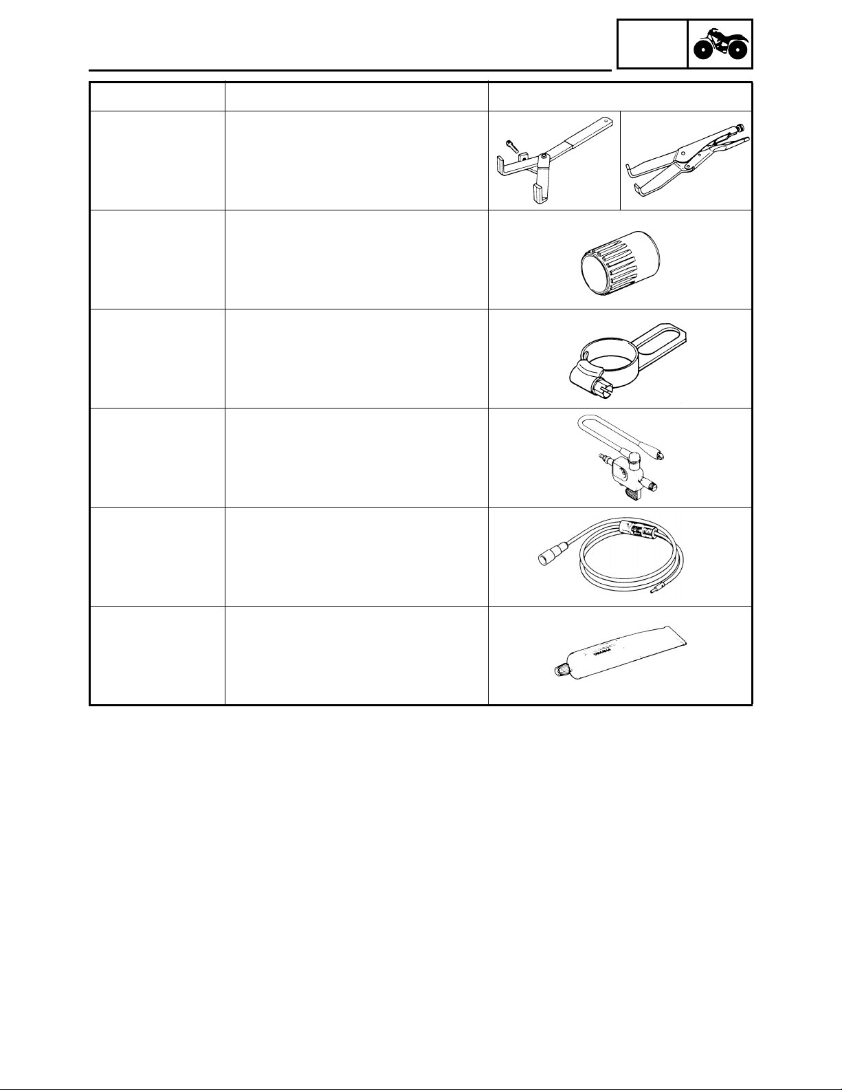
Slide hammer bolt (M6)/weight/set
These tools are used to remove the
rocker arm shafts.
Crankcase separating tool
This tool is used to separate the
crankcase.
Valve guide remover (7.0 mm)
This tool is needed to remove and
install the valve guides.
Valve guide installer (7.0 mm)
This tool is needed to install the valve
guides.
Valve guide reamer (7.0 mm)
90890-01227
YM-01227
90890-01235
YU-01235
90890-04088
Bolt
90890-01275
This tool is needed to rebore the new
valve guides.
Rotor holding tool
This tool is needed to hold the starter
pulley when removing/installing the
starter pulley bolt or camshaft
sprocket bolt.
Buffer boss installer set
Crankshaft installer bolt
These tools are used to install the
crankshaft.
1 - 5
Page 22

GEN
SPECIAL TOOLS
Tool No. Tool name/How to use Illustration
Crankshaft installer set
YU-90050
These tools are used to install the
crankshaft.
INFO
Adapter
YM-33279
Spacer
90890-04060
YM-90070-A
90890-01304
YU-01304
90890-01311
YU-08035
90890-01312
YM-01312-A
Adapter #11
Spacer (crankshaft)
These tools are used to install the
crankshaft.
Piston pin puller set
This tool is used to remove the piston
pin.
Tappet adjusting tool
This tool is necessary for adjusting
the valve clearance.
Fuel level gauge
This gauge is used to measure the
fuel level in the float chamber.
Radiator cap tester
90890-01325
YU-24460-01
90890-01352
YU-33984
90890-01348
YM-01348
90890-04134
YM-04134
This tool is used to check the cooling
systems.
Adapter
This tool is used to check the cooling
systems.
Locknut wrench
This tool is needed when removing or
installing the secondary sheave
spring.
Sheave spring compressor
This tool is needed when removing or
installing the secondary sheave
spring.
1 - 6
Page 23

GEN
SPECIAL TOOLS
Tool No. Tool name/How to use Illustration
Sheave fixed block
INFO
90890-04135
YM-04135
90890-01404
YM-01404
90890-01327
YM-01327
90890-01426
YU-38411
90890-01430
YM-38404
This tool is needed when removing or
installing the secondary sheave
spring.
Flywheel puller
These tools are needed to remove
the rotor.
Damper rod holder (30 mm)
This tool is needed to loosen and
tighten the steering stem bearing
retainers.
Oil filter wrench
This tool is needed to loosen or
tighten the oil filter cartridge.
Ring nut wrench
This tool is needed to removing and
installing the middle driven shaft
bearing retainers.
90890-01467
YM-01467
90890-01475
YM-01475
90890-01474
YM-01474
YM-01477
90890-01701
YS-01880-A
Gear lash measurement tool
This tool is used to measure the gear
lash.
Ball joint remover/installer set
This tool is used to remove and install
the ball joints.
Ball joint remover/installer attachment
set
This tool is used to remove and install
the ball joints.
Sheave holder
This tool is needed to hold the
primary sheave when removing or
installing the sheave bolts.
1 - 7
Page 24

GEN
SPECIAL TOOLS
Tool No. Tool name/How to use Illustration
INFO
Compression gauge
90890-03081
YU-33223
Adapter
90890-04082
YU-33223-3
90890-03112
YU-03112-C
90890-03113
YU-8036-B
Compression gauge
Adapter
These tools are needed to measure
engine compression.
Pocket tester
This instrument is needed for
checking the electrical system.
Engine tachometer
This tool is needed for observing
engine rpm.
Inductive self-powered tachometer
This tool is needed for observing
engine rpm.
Timing light
90890-03141
YM-33277-A
90890-04019
YM-04019
Middle driven shaft
bearing driver
90890-04058
YM-04058-1
Mechanical seal installer
90890-04078
YM-33221
90890-04050
YM-04050
90890-04062
YM-04062
This tool is necessary for checking
ignition timing.
Valve spring compressor
This tool is needed to remove and
install the valve assemblies.
Middle driven shaft bearing driver
Mechanical seal installer
These tools are used to install the
water pump seals.
Bearing retainer wrench
This tool is needed when removing or
installing the final drive shaft bearing
retainers.
Universal joint holder
This tool is needed when removing or
installing the universal joint yoke nuts.
1 - 8
Page 25
GEN
SPECIAL TOOLS
Tool No. Tool name/How to use Illustration
Clutch holding tool
INFO
90890-04086
YM-91042
90890-04128
YM-04128
90890-04129
YM-04129
90890-06754
This tool is needed to hold the clutch
carrier when removing or installing
the carrier nut.
Bearing retainer wrench
This tool is needed when removing or
installing the middle driven pinion
gear bearing retainers.
Pinion gear fix clamp
This tool is used to hold the shift cam.
Ignition checker
This instrument is necessary for
checking the ignition system
components.
Dynamic spark tester
YM-34487
Bond
90890-85505
Sealant
ACC-11001-05-01
This instrument is necessary for
checking the ignition system
components.
Yamaha bond No. 1215
Sealant (Quick Gasket
This sealant (bond) is used on
crankcase mating surfaces, etc.
®
)
1 - 9
Page 26

GENERAL SPECIFICATIONS
SPECIFICATIONS
GENERAL SPECIFICATIONS
Item Standard
Model code: 5TE1, 5TE5
Dimensions:
Overall length 1,984 mm (78.1 in)
Overall width 1,085 mm (42.7 in)
Overall height 1,120 mm (44.1 in)
Seat height 827 mm (32.6 in)
Wheelbase 1,233 mm (48.5 in)
Minimum ground clearance 245 mm (9.7 in)
Minimum turning radius 3,000 mm (118.1 in)
Basic weight:
With oil and full fuel tank 265 kg (584 lb)
Engine:
Engine type Liquid-cooled 4-stroke, SOHC
Cylinder arrangement Forward-inclined single cylinder
Displacement 401 cm
Bore × stroke 84.5 × 71.5 mm (3.33 × 2.81 in)
Compression ratio 10.5 : 1
Standard compression pressure (at sea level) 1,400 kPa (14.0 kg/cm
Starting system Electric and recoil starter
Lubrication system: Wet sump
Oil type or grade:
Engine oil
3
2
SPEC
2
, 203 psi) at 750 r/min
API service SE, SF, SG type or higher
Final gear oil SAE 80API “GL-4” Hypoid Gear Oil
Differential gear oil SAE 80API “GL-4” Hypoid Gear Oil
Oil capacity:
Engine oil
Periodic oil change 2.3 L (2.0 Imp qt, 2.4 US qt)
With oil filter replacement 2.4 L (2.1 Imp qt, 2.5 US qt)
Total amount 2.6 L (2.3 Imp qt, 2.7 US qt)
Final gear case oil
Periodic oil change 0.23 L (0.20 Imp qt, 0.24 US qt)
Total amount 0.25 L (0.22 Imp qt, 0.26 US qt)
2 - 1
Page 27

GENERAL SPECIFICATIONS
Item Standard
Differential gear case oil
Periodic oil change 0.35 L (0.31 Imp qt, 0.37 US qt)
Total amount 0.40 L (0.35 Imp qt, 0.42 US qt)
Radiator capacity (including all routes) 1.32 L (1.16 Imp qt, 1.40 US qt)
Air filter: Wet type element
Fuel:
Type Unleaded fuel
Fuel tank capacity 15 L (3.3 Imp gal, 3.9 US gal)
Fuel reserve amount 4.5 L (0.99 Imp gal, 1.19 US gal)
Carburetor:
Type/quantity BSR33/1
Manufacturer MIKUNI
Spark plug:
Type/manufacturer DR8EA/NGK
Spark plug gap 0.6 ~ 0.7 mm (0.024 ~ 0.028 in)
Clutch type: Wet, centrifugal automatic
Transmission:
Primary reduction system V-belt
Secondary reduction system Spur gear
Secondary reduction ratio 39/24 × 24/18 × 33/9 (7.944)
Transmission type V-belt automatic
Operation Left hand operation
Single speed automatic 2.55 ~ 0.75 : 1
Sub transmission ratio 38/23 (1.652)
Reverse gear 29/17 (1.706)
Chassis:
Frame type Steel tube frame
Caster angle 4°
Camber angle 1°
Kingpin angle 11°
Kingpin offset 0 mm (0 in)
Trail 21 mm (0.83 in)
Tread (STD) front 850 mm (33.46 in)
rear 825 mm (32.48 in)
Toe-in 0 ~ 10 mm (0 ~ 0.39 in)
Tires:
Type Tubeless
Size front AT25 × 8–12
rear AT25 × 10–12
Manufacturer front MAXXIS
rear MAXXIS
Type front M911Y
rear M912Y
SPEC
2 - 2
Page 28

GENERAL SPECIFICATIONS
Item Standard
Tire pressure (cold tire):
Maximum load* 210 kg (463 lb)
Off-road riding front 22 ~ 28 kPa (0.22 ~ 0.28 kg/cm
rear 22 ~ 28 kPa (0.22 ~ 0.28 kg/cm
*Load in total weight of rider accessories
Brakes:
Front brake type Dual disc brake
operation Right hand operation
Rear brake type Drum brake
operation Left hand and right foot operation
Suspension:
Front suspension Double wishbone
Rear suspension Swingarm (monocross)
Shock absorbers:
Front shock absorber Coil spring/oil damper
Rear shock absorber Coil spring/oil damper
Wheel travel:
Front wheel travel 160 mm (6.30 in)
Rear wheel travel 180 mm (7.09 in)
Electrical:
Ignition system D.C. C.D.I.
Generator system A.C. magneto
Battery type YTX14AH
Battery capacity 12 V 12 Ah
Headlight type: Halogen bulb
Bulb wattage × quantity:
Headlight 12 V 30 W/30 W × 2
Tail/brake light 12 V 5 W/21 W
Meter light 14 V 3 W × 1
Indicator lights
Neutral 12 V 1.7 W × 1
Reverse 12 V 1.7 W × 1
Coolant temperature 12 V 1.7 W × 1
Four-wheel drive 14 V 1.7 W × 1
SPEC
2
, 3.2 ~ 4.0 psi)
2
, 3.2 ~ 4.0 psi)
2 - 3
Page 29

MAINTENANCE SPECIFICATIONS
SPEC
MAINTENANCE SPECIFICATIONS
ENGINE
Item Standard Limit
Cylinder head:
Warp limit ---- 0.03 mm
(0.0012 in)
Cylinder:
Bore size 84.500 ~ 84.510 mm
(3.3268 ~ 3.3272 in)
Taper limit ---- 0.05 mm
Out of round limit ---- 0.01 mm
Camshaft:
Drive method Chain drive (left) ----
Cam dimensions
84.600 mm
(3.3307 in)
(0.0016 in)
(0.0004 in)
A
B
Intake “A” 40.62 ~ 40.72 mm
(1.5992 ~ 1.6031 in)
“B” 32.18 ~ 32.28 mm
(1.2669 ~ 1.2709 in)
Exhaust “A” 40.62 ~ 40.72 mm
(1.5992 ~ 1.6031 in)
“B” 32.18 ~ 32.28 mm
(1.2669 ~ 1.2709 in)
Camshaft runout limit ---- 0.03 mm
40.52 mm
(1.5953 in)
32.08 mm
(1.2630 in)
40.52 mm
(1.5953 in)
32.08 mm
(1.2630 in)
(0.0012 in)
2 - 4
Page 30

MAINTENANCE SPECIFICATIONS
SPEC
Item Standard Limit
Cam chain:
Cam chain type/No. of links DID SCR-0409 SDH/116 ----
Cam chain adjustment method Automatic ---Rocker arm/rocker arm shaft:
Bearing inside diameter 12.000 ~ 12.018 mm
(0.4724 ~ 0.4731 in)
Shaft outside diameter 11.981 ~ 11.991 mm
(0.4717 ~ 0.4721 in)
Arm-to-shaft clearance 0.009 ~ 0.037 mm
(0.0004 ~ 0.0015 in)
Valves, valve seats, valve guides:
Valve clearance (cold) IN 0.06 ~ 0.10 mm
(0.0024 ~ 0.0039 in)
EX 0.16 ~ 0.20 mm
(0.0063 ~ 0.0079 in)
Valve dimensions
12.078 mm
(0.4755 in)
11.951 mm
(0.4705 in)
0.080 mm
(0.0031 in)
----
----
A
Head Diameter
Face Width
B
Seat Width
C
Margin Thickness
“A” head diameter IN 39.9 ~ 40.1 mm
(1.5708 ~ 1.5787 in)
EX 33.9 ~ 34.1 mm
(1.3346 ~ 1.3425 in)
“B” face width IN 2.26 mm (0.0890 in) ----
EX 2.26 mm (0.0890 in) ----
“C” seat width IN 1.2 ~ 1.4 mm
(0.0472 ~ 0.0551 in)
EX 1.2 ~ 1.4 mm
(0.0472 ~ 0.0551 in)
“D” margin thickness IN 1.0 ~ 1.4 mm
(0.0394 ~ 0.0551 in)
EX 0.8 ~ 1.2 mm
(0.0315 ~ 0.0472 in)
Stem outside diameter IN 6.975 ~ 6.990 mm
(0.2746 ~ 0.2752 in)
EX 6.955 ~ 6.970 mm
(0.2738 ~ 0.2744 in)
Guide inside diameter IN 7.000 ~ 7.012 mm
(0.2756 ~ 0.2761 in)
EX 7.000 ~ 7.012 mm
(0.2756 ~ 0.2761 in)
Stem-to-guide clearance IN 0.010 ~ 0.037 mm
(0.0004 ~ 0.0015 in)
EX 0.030 ~ 0.057 mm
(0.0012 ~ 0.0022 in)
D
----
----
1.6 mm
(0.0630 in)
1.6 mm
(0.0630 in)
----
----
6.950 mm
(0.2736 in)
6.915 mm
(0.2722 in)
7.030 mm
(0.2768 in)
7.030 mm
(0.2768 in)
0.080 mm
(0.0031 in)
0.100 mm
(0.0039 in)
2 - 5
Page 31

MAINTENANCE SPECIFICATIONS
Item Standard Limit
Stem runout limit ---- 0.01 mm
SPEC
(0.0004 in)
Valve seat width IN 1.2 ~ 1.4 mm
(0.0472 ~ 0.0551 in)
EX 1.2 ~ 1.4 mm
(0.0472 ~ 0.0551 in)
Valve spring:
Inner spring
Free length IN 39.9 mm (1.57 in) 37.9 mm
EX 39.9 mm (1.57 in) 37.9 mm
Set length (valve closed) IN 33.6 mm (1.32 in) ----
EX 33.6 mm (1.32 in) ----
Compressed pressure
(installed) IN 104.9 ~ 120.6 N (10.70 ~
12.30 kg, 23.58 ~ 27.11 lb)
EX 104.9 ~ 120.6 N (10.70 ~
12.30 kg, 23.58 ~ 27.11 lb)
Tilt limit IN 2.5°/1.6 mm
*
EX 2.5°/1.6 mm
----
----
(1.49 in)
(1.49 in)
----
----
(2.5°/0.06 in)
(2.5°/0.06 in)
Direction of winding
(top view) IN Counterclockwise ----
EX Counterclockwise ----
Outer spring
Free length IN 43.27 mm (1.70 in) 41.27 mm
(1.62 in)
EX 43.27 mm (1.70 in) 41.27 mm
(1.62 in)
Set length (valve closed) IN 36.6 mm (1.44 in) ----
EX 36.6 mm (1.44 in) ----
Compressed pressure
(installed) IN 235.4 ~ 251.1 N (24.00 ~
25.60 kg, 52.91 ~ 56.45 lb)
EX 235.4 ~ 251.1 N (24.00 ~
25.60 kg, 52.91 ~ 56.45 lb)
----
----
2 - 6
Page 32

MAINTENANCE SPECIFICATIONS
Item Standard Limit
Tilt limit IN 2.5°/1.6 mm
Direction of winding
(top view) IN Clockwise ----
Piston:
Piston to cylinder clearance 0.040 ~ 0.065 mm
Piston size “D” 84.445 ~ 84.460 mm
*
EX 2.5°/1.6 mm
EX Clockwise ----
(0.0016 ~ 0.0026 in)
(3.3246 ~ 3.3252 in)
SPEC
(2.5°/0.06 in)
(2.5°/0.06 in)
0.150 mm
(0.0059 in)
----
H
D
Measuring point “H” 5 mm (0.20 in) ----
Piston offset 0.5 mm (0.0200 in) ----
Offset direction Intake side ----
Piston pin bore inside diameter 20.004 ~ 20.015 mm
(0.7876 ~ 0.7880 in)
Piston pin outside diameter 19.991 ~ 20.000 mm
(0.7870 ~ 0.7874 in)
Piston rings:
Top ring
B
T
Type Barrel ---Dimensions (B × T) 1.2 × 3.1 mm
(0.04724 × 0.1220 in)
End gap (installed) 0.20 ~ 0.40 mm
(0.0079 ~ 0.0157 in)
Side clearance (installed) 0.03 ~ 0.08 mm
(0.0012 ~ 0.0031 in)
20.045 mm
(0.7892 in)
19.971 mm
(0.7863 in)
----
0.65 mm
(0.0256 in)
0.13 mm
(0.0051 in)
2 - 7
Page 33
MAINTENANCE SPECIFICATIONS
Item Standard Limit
2nd ring
B
T
Type Taper ---Dimensions (B × T) 1.2 × 3.6 mm
(0.04724 × 0.1417 in)
End gap (installed) 0.40 ~ 0.60 mm
(0.0157 ~ 0.0236 in)
Side clearance 0.03 ~ 0.07 mm
(0.0012 ~ 0.0028 in)
Oil ring
B
T
SPEC
----
0.95 mm
(0.0374 in)
0.13 mm
(0.0051 in)
Dimensions (B × T) 2.8 × 2.8 mm
(0.1102 × 0.1102 in)
End gap (installed) 0.2 ~ 0.7 mm
(0.0079 ~ 0.0276 in)
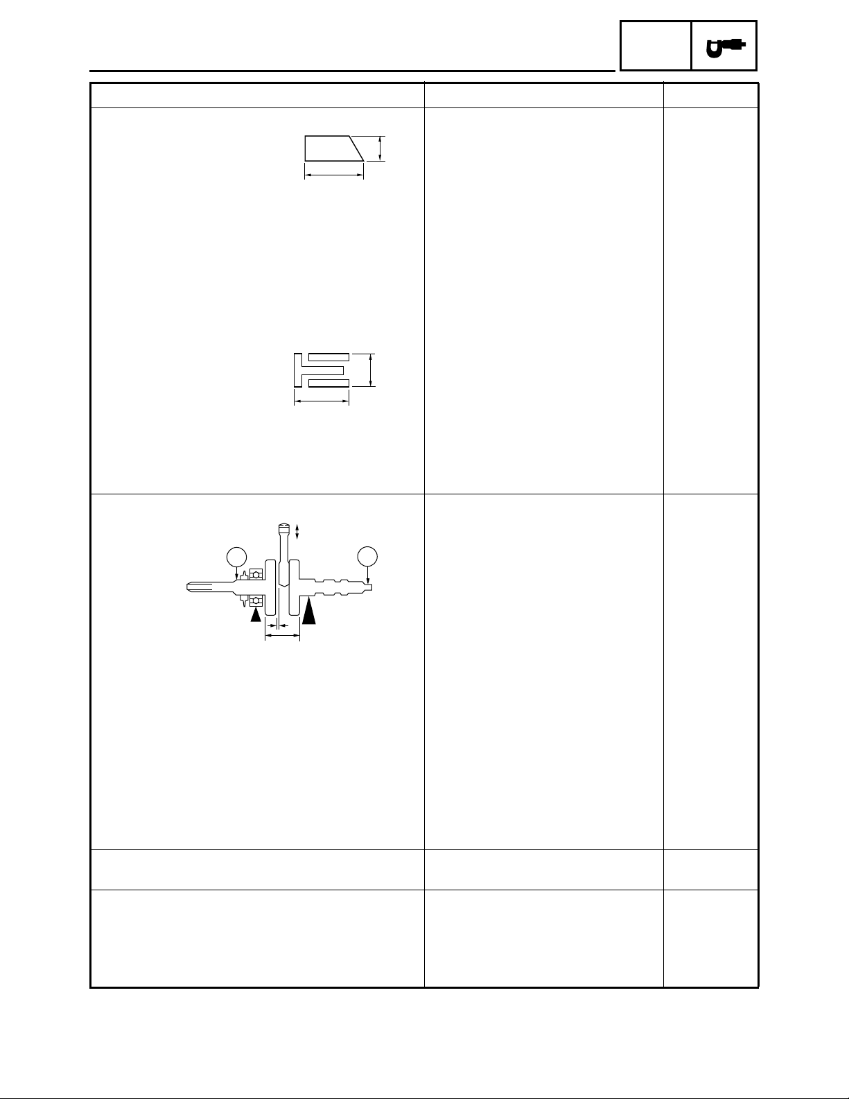
Crankshaft:
E
C1
B
A
Crank width “A” 62.95 ~ 63.00 mm
Runout limit C1 ---- 0.03 mm
C2 ---- 0.03 mm
Big end side clearance “B” 0.25 ~ 0.75 mm
Big end radial clearance “E” 0.010 ~ 0.025 mm
Balancer:
Balancer drive method Gear ---Automatic centrifugal clutch:
Clutch shoe thickness 1.5 mm (0.06 in) 1.0 mm
Clutch-in revolution 1,960 ~ 2,240 r/min ----
Clutch-stall revolution 3,300 ~ 3,900 r/min ----
C2
(2.4783 ~ 2.4803 in)
(0.0098 ~ 0.0295 in)
(0.0004 ~ 0.0010 in)
----
----
----
(0.0012 in)
(0.0012 in)
1.00 mm
(0.0394 in)
----
(0.04 in)
2 - 8
Page 34
MAINTENANCE SPECIFICATIONS
Item Standard Limit
Transmission:
Main axle deflection limit ---- 0.06 mm
Drive axle deflection limit ---- 0.06 mm
Shifter:
Shifter type Shift cam and guide bar ---Air filter oil grade: Engine oil ---Carburetor:
I. D. mark 5TE1 00 ----
Main jet (M.J) #132.5 ----
Main air jet (M.A.J) #50 ----
Jet needle (J.N) 5EP13-55-3 ----
Needle jet (N.J) P-0M ----
Pilot air jet (P.A.J.1) #80 ----
Pilot air jet (P.A.J.2) 1.3 ----
Pilot outlet (P.O) 0.95 ----
Pilot jet (P.J) #17.5 ----
Bypass 1 (B.P.1) 0.8 ----
Bypass 2 (B.P.2) 0.8 ----
Bypass 3 (B.P.3) 0.8 ----
Valve seat size (V.S) 2.0 ----
Starter jet (G.S.1) #75 ----
Starter jet (G.S.2) 0.9 ----
Throttle valve size (Th.V) #90 ----
Float height (F.H) 13 mm (0.51 in) ----
Fuel level (F.L) 4.0 ~ 5.0 mm (0.16 ~ 0.20 in) ----
Engine idle speed 1,450 ~ 1,550 r/min ----
Intake vacuum 32 kPa (240 mmHg, 9.45 inHg) ---Oil pump:
Oil filter type Foam ----
Oil pump type Trochoid ----
Tip clearance “A” or “B” 0.15 mm (0.006 in) 0.20 mm
Side clearance 0.04 ~ 0.09 mm
(0.002 ~ 0.004 in)
Bypass valve setting pressure 78 ~ 118 kPa (0.78 ~
1.18 kg/cm
Oil pressure (hot) 7 kPa (0.07 kg/cm
1,500 r/min
Pressure check location Cylinder head ----
2
, 11.3 ~ 17.11 psi)
2
, 1.02 psi) at
SPEC
(0.0024 in)
(0.0024 in)
(0.008 in)
----
----
----
2 - 9
Page 35
MAINTENANCE SPECIFICATIONS
SPEC
Item Standard Limit
Cooling system:
Radiator core
Width 300 mm (11.8 in) ---Height 208 mm (8.19 in) ---Thickness 26 mm (1.02 in) ----
Radiator cap opening pressure 93.7 ~ 122.6 kPa (0.937 ~
2
1.226 kg/cm
, 13.32 ~ 17.43 psi)
Radiator capacity 0.70 L (0.62 Imp qt, 0.74 US qt) ---Coolant reservoir
Capacity 0.39 L (0.34 Imp qt, 0.41 US qt) ---From low to full level 0.15 L (0.13 Imp qt, 0.16 US qt) ----
Water pump:
Type Single-suction centrifugal pump ---Reduction ratio 38/32 (1.188)
Thermostat:
Valve opening temperature 63.5 ~ 66.5 °C (146.3 ~ 151.7 °F) ----
Valve full open temperature 80 °C (176 °F) ----
Valve lift-full open 3 mm (0.12 in) ----
Shaft drive:
Middle gear backlash 0.1 ~ 0.3 mm (0.004 ~ 0.012 in) ---Final gear backlash 0.1 ~ 0.2 mm (0.004 ~ 0.008 in) ---Differential gear backlash 0.10 ~ 0.50 mm
(0.004 ~ 0.020 in)
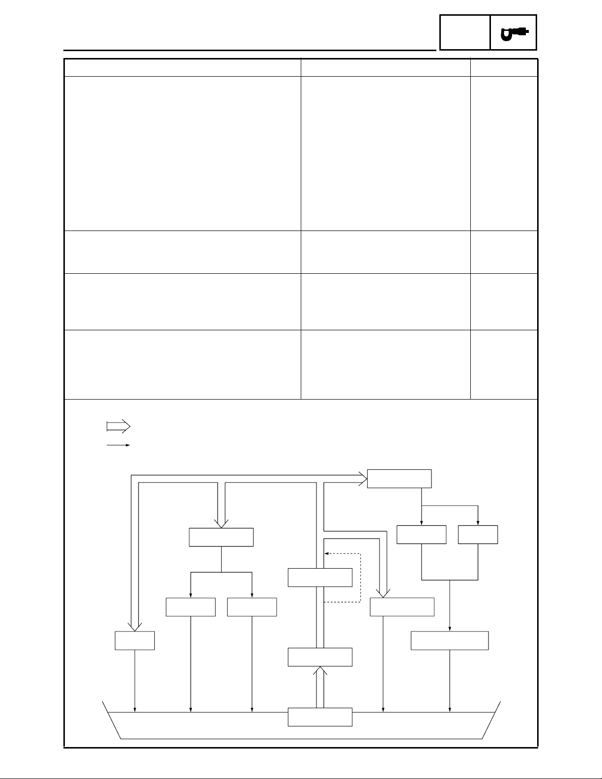
Lubrication chart:
----
----
Pressure feed
Splashed scavenge
Piston
Clutch
Crank Pin
Piston Pin
Oil Filter
Bypass
Oil Pump
Valve
Camshaft
Rocker Arm
Transmission
Timing Chain Area
Valve
Oil Strainer
2 - 10
Page 36
MAINTENANCE SPECIFICATIONS
Item Standard Limit
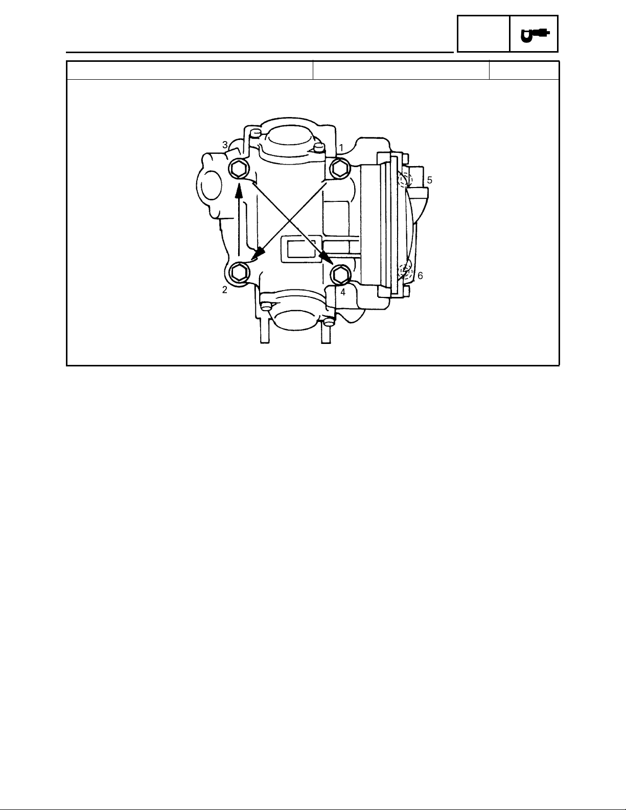
Cylinder head tightening sequence:
SPEC
2 - 11
Page 37
Tightening torques
MAINTENANCE SPECIFICATIONS
SPEC
Part to be tightened
Cylinder head oil passage
Cylinder head (exhaust pipe)
Part
name
Union bolt
Stud bolt
Thread
size
Q’ty
M6 1 7 0.7 5.1
M8 2 15 1.5 11
Tightening torque
Remarks
Nm m·kg ft·lb
Cylinder head Bolt M10 4 40 4.0 29
Bolt M6 2 10 1.0 7.2
Camshaft sprocket cover baffle
Bolt M6 2 10 1.0 7.2
plate
Camshaft bearing retainer Bolt M6 2 8 0.8 5.8
Spark plug — M12 1 18 1.8 13
Coolant drain bolt (cylinder) Bolt M6 1 10 1.0 7.2
Starter clutch Bolt M10 1 50 5.0 36
Camshaft sprocket Bolt M10 1 60 6.0 43
Timing chain tensioner cap Bolt M11 1 23 2.3 17
Timing chain tensioner Bolt M6 2 11 1.1 8.0
Timing chain guide (intake) Bolt M6 2 10 1.0 7.2
Valve adjusting screw Nut M7 2 20 2.0 14
Radiator Bolt M6 2 7 0.7 5.1
Oil pump assembly Screw M6 3 8 0.8 5.8
Oil pump Screw M6 1 7 0.7 5.1
Oil strainer cover Plug M35 1 32 3.2 23
Oil drain bolt Bolt M14 1 23 2.3 17
Oil pump drive gear Nut M14 1 50 5.0 36
Oil delivery pipe
Oil filter bolt
Union bolt
Union bolt
M8 2 18 1.8 13
M20 1 63 6.3 45
Oil filter cartridge — M20 1 17 1.7 12
Intake manifold Bolt M8 2 20 2.0 14
Muffler and exhaust pipe Bolt M8 2 15 1.5 11
Exhaust pipe Nut M8 2 20 2.0 14
Muffler Bolt M10 2 25 2.5 18
Exhaust pipe bracket Bolt M6 2 14 1.4 10
Crankcase cover Screw M6 4 8 0.8 5.8
Oil seal retainer Screw M5 3 7 0.7 5.1
Drive belt case cover Bolt M6 12 10 1.0 7.2
Crankcase oil passage plug Plug M18 1 55 5.5 40
Bearing retainer (right crankcase) Screw M6 1 11 1.1 8.0
Plug (right crankcase) Bolt M8 1 15 1.5 11
Bearing retainer (left crankcase) Bolt M6 2 10 1.0 7.2
Crankcase cover (left) Bolt M6 12 10 1.0 7.2
Recoil starter
Bolt M6 4 10 1.0 7.2
Starter one-way clutch Bolt M8 6 30 3.0 22
Clutch carrier assembly Nut M22 1 140 14 100 Stake
Middle drive shaft bearing retainer Torx
M8 4 25 2.5 18
screw
LT
LT
E
LT
LT
LT
LT
LT
LT
2 - 12
Page 38
MAINTENANCE SPECIFICATIONS
SPEC
Part to be tightened
Part
name
Thread
size
Q’ty
Tightening torque
Remarks
Nm m·kg ft·lb
Middle driven shaft drive pinion gear Nut M22 1 130 13 94 Stake
Middle drive shaft bearing housing Bolt M8 6 32 3.2 23
Middle driven gear bearing retainer Nut M65 1 110 11 80
Left-hand threads
Yoke (middle driven gear) Nut M14 1 97 9.7 70
Middle driven gear bearing housing Bolt M8 4 25 2.5 18
Middle driven shaft bearing retainer Nut M55 1 80 8.0 58
Left-hand threads
Shift rod Nut M8 2 15 1.5 11
Primary sliding sheave assembly Nut M16 1 100 10.0 72
Secondary sheave assembly Nut M16 1 100 10.0 72
Secondary sheave spring retainer Nut M36 1 90 9.0 65
Shift lever 2 Bolt M6 1 14 1.4 10
Shift control cable — M12 1 6 0.6 4.3
Select lever unit Bolt M8 3 15 1.5 11
Shift cam stopper — M14 1 18 1.8 13
CDI unit Screw M6 1 2 0.2 1.4
Neutral switch — M10 1 20 2.0 14
Reverse switch — M10 1 20 2.0 14
Stator assembly Screw M6 3 7 0.7 5.1
Pickup coil Bolt M5 2 7 0.7 5.1
Ignition coil Bolt M6 2 7 0.7 5.1
Thermo switch (cylinder head) — PT1/8 1 8 0.8 5.8
Speed sensor Bolt M6 1 10 1.0 7.2
Thermo switch (radiator) — M18 1 28 2.8 20
Tappet covers Bolt M6 4 10 1.0 7.2
Coolant drain bolt (water pump) Bolt M6 1 10 1.0 7.2
Coolant inlet joint Bolt M6 2 10 1.0 7.2
Bearing housing Bolt M6 1 10 1.0 7.2
Primary pulley sheave cap Screw M4 4 3 0.3 2.2
Clutch housing assembly Bolt M6 8 10 1.0 7.2
Clutch housing assembly cover Bolt M6 5 10 1.0 7.2
Starter motor Bolt M6 2 10 1.0 7.2
Engine side cover bracket Bolt M6 2 10 1.0 7.2
Crankcase Bolt M6 17 10 1.0 7.2
Thermostat cover Bolt M6 2 10 1.0 7.2
Water pump outlet pipe Bolt M6 1 10 1.0 7.2
Water pump assembly Bolt M6 2 10 1.0 7.2
Gear unit Bolt M6 2 10 1.0 7.2
Screw M6 1 7 0.7 5.1
LT
LT
LT
LT
LT
LT
LT
2 - 13
Page 39

MAINTENANCE SPECIFICATIONS
CHASSIS
Item Standard Limit
Steering system:
Steering bearing type Ball and race bearing ----
Front suspension:
Shock absorber travel 99 mm (3.90 in) ---Fork spring free length 265 mm (10.43 in) ---Spring fitting length 215.8 mm (8.50 in) ---Spring rate (K1) 15 N/mm (1.53 kg/mm, 85.68 lb/in) ---Stroke (K1) 0 ~ 99 mm (0 ~ 3.90 in) ---Optional spring No ----
Rear suspension:
Shock absorber travel 126 mm (4.96 in) ---Spring free length 317 mm (12.48 in) ---Spring fitting length 283 mm (11.14 in) ---Spring rate (K1) 30.4 N/mm
(3.10 kg/mm, 173.60 lb/in)
Stroke (K1) 0 ~ 126 mm (0 ~ 4.96 in) ---Optional spring No ----
Swingarm:
Free play limit end ---- 1 mm
side ---- 1 mm
Front wheel:
Type Panel wheel ---Rim size 12 × 6.0 AT ---Rim material Steel ---Rim runout limit radial ---- 2 mm
lateral ---- 2 mm
Rear wheel:
Type Panel wheel ---Rim size 12 × 7.5 AT ---Rim material Steel ---Rim runout limit radial ---- 2 mm
lateral ---- 2 mm
SPEC
----
(0.04 in)
(0.04 in)
(0.08 in)
(0.08 in)
(0.08 in)
(0.08 in)
2 - 14
Page 40
MAINTENANCE SPECIFICATIONS
Item Standard Limit
Front disc brake:
Type Dual ---Disc outside diameter × thickness 200.0 × 3.5 mm (7.87 ~ 0.14 in) ---Pad thickness inner 4.5 mm (0.18 in) 1 mm
Pad thickness outer 4.5 mm (0.18 in) 1 mm
Master cylinder inside diameter 14 mm (0.55 in) ---Caliper cylinder inside diameter 32 mm (1.26 in) ---Brake fluid type DOT 4 ----
Rear drum brake:
Type Leading, trailing ---Brake drum inside diameter 160 mm (6.30 in) 161 mm
Lining thickness 4.0 mm (0.16 in) 2 mm
Brake lever and brake pedal:
Brake lever free play (pivot) front 0 mm (0 in) ----
rear 3 ~ 5 mm (0.12 ~ 0.20 in) ---Brake pedal free play 20 ~ 30 mm (0.79 ~ 1.18 in) ---Throttle lever free play 3 ~ 5 mm (0.12 ~ 0.20 in) ----
SPEC
(0.04 in)
(0.04 in)
(6.34 in)
(0.08 in)
2 - 15
Page 41
Tightening torques
MAINTENANCE SPECIFICATIONS
SPEC
Part to be tightened Thread size
Remarks
Nm m·kg ft·lb
Engine bracket (front-upper) and frame M8 33 3.3 24
Engine bracket (front-lower) and frame M8 33 3.3 24
Engine bracket (front-upper) and engine M10 42 4.2 30
Engine bracket (front-lower) and engine M10 42 4.2 30
Engine and frame M10 56 5.6 40
Tightening torque
Frame and bearing retainer (steering stem holder
M42 40 4.0 29
bearing)
Select lever assembly and frame M8 23 2.3 17
Swingarm M12 82 8.2 60
Rear shock absorber and frame M12 82 8.2 60
Final gear case and swingarm M10 63 6.3 45
LT
Final gear case and rear axle housing M10 63 6.3 46
Swingarm and rear axle housing M10 63 6.3 46
Differential gear case and frame M10 55 5.5 40
Front arm and frame M10 45 4.5 32
LS
Front shock absorber and frame M10 45 4.5 32
Front shock absorber and upper front arm M10 45 4.5 32
Steering stem, pitman arm and frame M14 130 13.0 94
LS
Steering stem holder and frame M8 23 2.3 17 Use lock
washer
Steering stem and handlebar holder M8 23 2.3 17
Pitman arm and tie-rod end M12 30 3.0 22
Tie-rod and locknut M12 40 4.0 29
Steering knuckle and upper front arm M12 30 3.0 22
Steering knuckle and lower front arm M12 30 3.0 22
LS
Steering knuckle and tie-rod M12 30 3.0 22
Fuel tank and fuel cock M6 4 0.4 2.9
Front wheel and wheel hub M10 64 6.4 46
Front axle and wheel hub M16 150 15.0 110
Steering knuckle and brake caliper M8 30 3.0 22
Front brake disc and wheel hub M8 30 3.0 22
LT
Rear wheel and rear wheel hub M10 55 5.5 40
Rear axle and nut M16 150 15.0 110
Brake drum cover and brake shoe plate M6 28 2.8 20
LT
Front brake pipe nut M10 19 1.9 13
Front brake hose union bolt M10 27 2.7 19
Bleed screw M8 6 0.6 4.3
Master cylinder and handlebar M6 7 0.7 5.1
Footrest and frame M8 16 1.6 11
2 - 16
Page 42

MAINTENANCE SPECIFICATIONS
SPEC
Part to be tightened Thread size
Tightening torque
Nm m·kg ft·lb
Front bumper and frame M8 33 3.3 24
Front carrier and frame M8 33 3.3 24
Front carrier and front bumper M8 33 3.3 24
Rear carrier and frame M8 33 3.3 24
Differential gear case filler bolt M14 23 2.3 17
Differential gear case drain bolt M10 10 1.0 7
Differential gear case and bearing housing M8 25 2.5 18
Gear motor M8 13 1.3 9.4
Final gear case oil filler bolt M14 23 2.3 17
Final gear case oil drain bolt M14 23 2.3 17
Bearing retainer (drive pinion gear) M65 100 10.0 72
Final gear case and bearing housing M10 40 4.0 29
Final gear case and bearing housing M8 23 2.3 17
Battery holding bracket M6 7 0.7 5.1
Footrest board and footrest bracket M6 7 0.7 5.1
Yoke (drive pinion gear) M12 62 6.2 45
Trailer hitch bracket M10 32 3.2 23
Front brake pad holding bolt M10 18 1.8 13
Rear brake light switch bracket M8 23 2.3 17
Rear brake light switch cover M6 7 0.7 5.1
Front brake caliper retaining bolt M8 30 3.0 22
Air duct (front) M6 7 0.7 5.1
Rear brake lever holder bracket M6 7 0.7 5.1
Rear brake lever (bolt) M6 7 0.7 5.1
Rear brake lever (nut) M6 7 0.7 5.1
Brake camshaft lever M6 9 0.9 6.5
Four-wheel drive switch M10 20 2.0 14
Remarks
2 - 17
Page 43

MAINTENANCE SPECIFICATIONS
ELECTRICAL
Item Standard Limit
Voltage: 12 V ---Ignition system:
Ignition timing (B.T.D.C.) 10°/ 1,500 r/min ----
C.D.I.:
Magneto model/manufacturer F4T46472/MITSUBISHI ---Pickup coil resistance/color 459 ~ 561 Ω at 20 °C (68 °F)/
White/Red – White/Green
Rotor rotation direction sensing coil
resistance/color
C.D.I. unit model/manufacturer F8T38679/MITSUBISHI ----
Ignition coil:
Model/manufacturer 2JN/YAMAHA ---Minimum spark gap 6 mm (0.24 in) ---Primary winding resistance 0.18 ~ 0.28 Ω at 20 °C (68 °F) ---Secondary winding resistance 6.32 ~ 9.48 kΩ at 20 °C (68 °F) ----
Spark plug cap:
Type Resin ---Resistance 10 kΩ ----
Charging system:
Type A.C. magneto generator ---Model/manufacturer F4T464/MITSUBISHI ---Nominal output 14 V 17.5 A at 5,000 r/min ---Charging coil resistance/color 0.46 ~ 0.62 Ω at 20 °C (68 °F)/
Rectifier/regulator:
Regulator type Semi conductor-short circuit ---No-load regulated voltage (DC) 14.1 ~ 14.9 V ---Model/manufacturer SH640E-11/SHINDENGEN ---Capacity 14 A ---Withstand voltage 200 V ----
Electric starter system:
Type Constant mesh ---Starter motor
Model/manufacturer SM-13/MITSUBA ---Output 0.8 kW ---Armature coil resistance 0.025 ~ 0.035 Ω at 20 °C (68 °F) ----
0.085 ~ 0.105 Ω at 20 °C (68 °F)/
Red – White/Blue
White – White
SPEC
----
----
----
2 - 18
Page 44

MAINTENANCE SPECIFICATIONS
Item Standard Limit
Brush overall length 12.5 mm (0.49 in) 5 mm
Spring force 7.65 ~ 10.01 N (780 ~ 1,020 g,
27.54 ~ 36.03 oz)
Commutator diameter 28 mm (1.10 in) 27 mm
Mica undercut 0.7 mm (0.03 in) ----
Starter relay
Model/manufacturer MS5F-561/JIDECO ---Amperage rating 180 A ---Coil winding resistance 4.18 ~ 4.62 Ω at 20 °C (68 °F) ----
Electric fan:
Running rpm 3,500 r/min ----
Thermostat switch:
Thermostat switch (cylinder head)
Model/manufacturer 4BA/DENSO ----
Thermostat switch (radiator)
Model/manufacturer 5ND/NIPPON THERMOSTAT ----
Circuit breakers:
Type Fuse ---Amperage for individual circuit
Main fuse 30 A × 1 ---Headlight fuse 15 A × 1 ---Ignition fuse 10 A × 1 ---Auxiliary DC jack fuse 10 A × 1 ---Four-wheel drive fuse 3 A × 1 ---Signaling system fuse 10 A × 1 ---Reserve 30 A × 1 ---Reserve 15 A × 1 ---Reserve 10 A × 1 ---Reserve 3 A × 1 ----
SPEC
(0.20 in)
----
(1.06 in)
2 - 19
Page 45

HOW TO USE THE CONVERSION TABLE/
GENERAL TORQUE SPECIFICATIONS
SPEC
EB201000
HOW TO USE THE CONVERSION
TABLE
All specification data in this manual are listed in
SI and METRIC UNITS.
Use this table to convert METRIC unit data to
IMPERIAL unit data.
Ex.
METRIC MULTIPLIER IMPERIAL
** mm
2 mm
CONVERSION TABLE
Torque
Weight
Speed km/hr 0.6214 mph
Distance
Volume/
Capacity
Misc.
×
0.03937 = ** in
×
0.03937 = 0.08 in
METRIC TO IMPERIAL
Metric unit Multiplier Imperial unit
m·kg
m·kg
cm·kg
cm·kg
kg
g
km
m
m
cm
mm
cc (cm
cc (cm3)
lt (liter)
lt (liter)
kg/mm
kg/cm
Centigrade
(°C)
3
)
2
7.233
86.794
0.0723
0.8679
2.205
0.03527lboz
0.6214
3.281
1.094
0.3937
0.03937
0.03527
0.06102
0.8799
0.2199
55.997
14.2234
9/5+32
ft·lb
in·lb
ft·lb
in·lb
mi
ft
yd
in
in
oz (IMP liq.)
cu·in
qt (IMP liq.)
gal (IMP liq.)
lb/in
psi (lb/in
Fahrenheit (°F)
2
)
EB202001
GENERAL TORQUE
SPECIFICATIONS
This chart specifies torque for standard
fasteners with standard I.S.O. pitch threads.
Torque specifications for special components
or assemblies are provided for each chapter of
this manual. To avoid warpage, tighten multifastener assemblies in a crisscross fashion, in
progressive stages, until the specified torque is
reached. Unless otherwise specified, torque
specifications require clean, dry threads.
Components should be at room temperature.
A: Distance between flats
B: Outside thread diameter
A
(nut)
B
(bolt)
10 mm 6 mm 6 0.6 4.3
12 mm 8 mm 15 1.5 11
14 mm 10 mm 30 3.0 22
General torque
specifications
Nm m•kg ft•lb
2 - 20
17 mm 12 mm 55 5.5 40
19 mm 14 mm 85 8.5 61
22 mm 16 mm 130 13.0 94
Page 46

LUBRICATION POINTS AND LUBRICANT TYPES
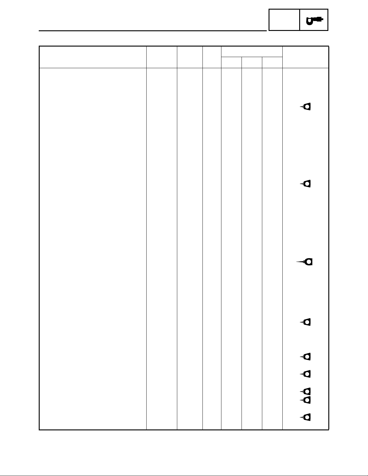
LUBRICATION POINTS AND LUBRICANT TYPES
ENGINE
Lubrication points Lubricant type
SPEC
Oil seal lip (all)
O-ring (all)
Bearing (all)
Crank pin
Connecting rod (bearing)
Camshaft sprocket
Crankshaft
Piston surface/piston rings
Piston pin
Buffer boss
Valve stem/valve stem end
Rocker arm shaft
Rocker arm
Camshaft lobe/journal
Cylinder head bolt
Oil pump shaft, rotor, housing
LS
LS
E
E
E
M
E
E
E
E
M
E
M
M
E
E
Oil filter O-ring
Starter idle gear shaft
Transmission gear (wheel/pinion)
Axle (main/drive)
Shift fork/guide bar
Shift cam/shift shaft/shift cam stopper
Shift guide
Shift cam lever
Clutch housing
One-way bearing
Drive chain/sprocket
Driven cam
Front drive shaft collar
Crankcase mating surface
Stator lead grommet
(left side crankcase)
E
E
M
M
E
E
LS
M
E
M
E
M
E
Sealant (Quick Gasket
Yamaha Bond No.1215
Sealant (Quick Gasket
Yamaha Bond No.1215
®
)
®
)
2 - 21
Page 47

COOLANT FLOW DIAGRAMS
COOLANT FLOW DIAGRAMS
1 Radiator
2 Thermo switch (radiator)
3 Fan motor
È To coolant reservoir
SPEC
2 - 22
Page 48
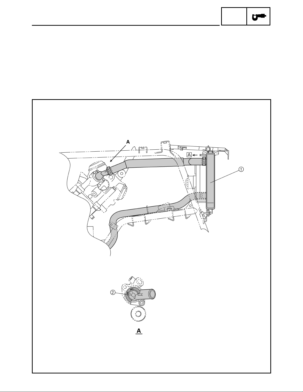
1 Radiator
2 Thermostat
È To coolant reservoir
COOLANT FLOW DIAGRAMS
SPEC
2 - 23
Page 49
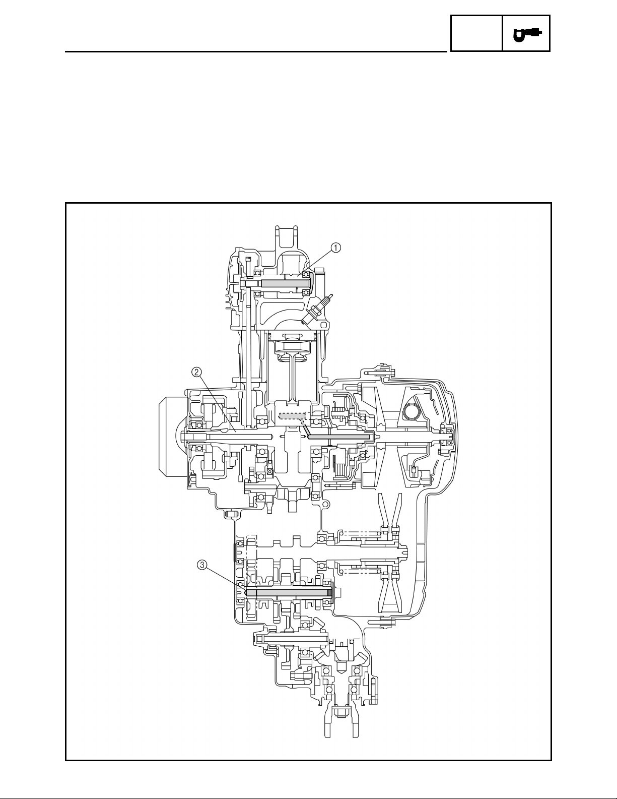
OIL FLOW DIAGRAMS
1 Camshaft
2 Crankshaft
3 Drive axle
OIL FLOW DIAGRAMS
SPEC
2 - 24
Page 50

1 Oil filter
OIL FLOW DIAGRAMS
SPEC
2 - 25
Page 51
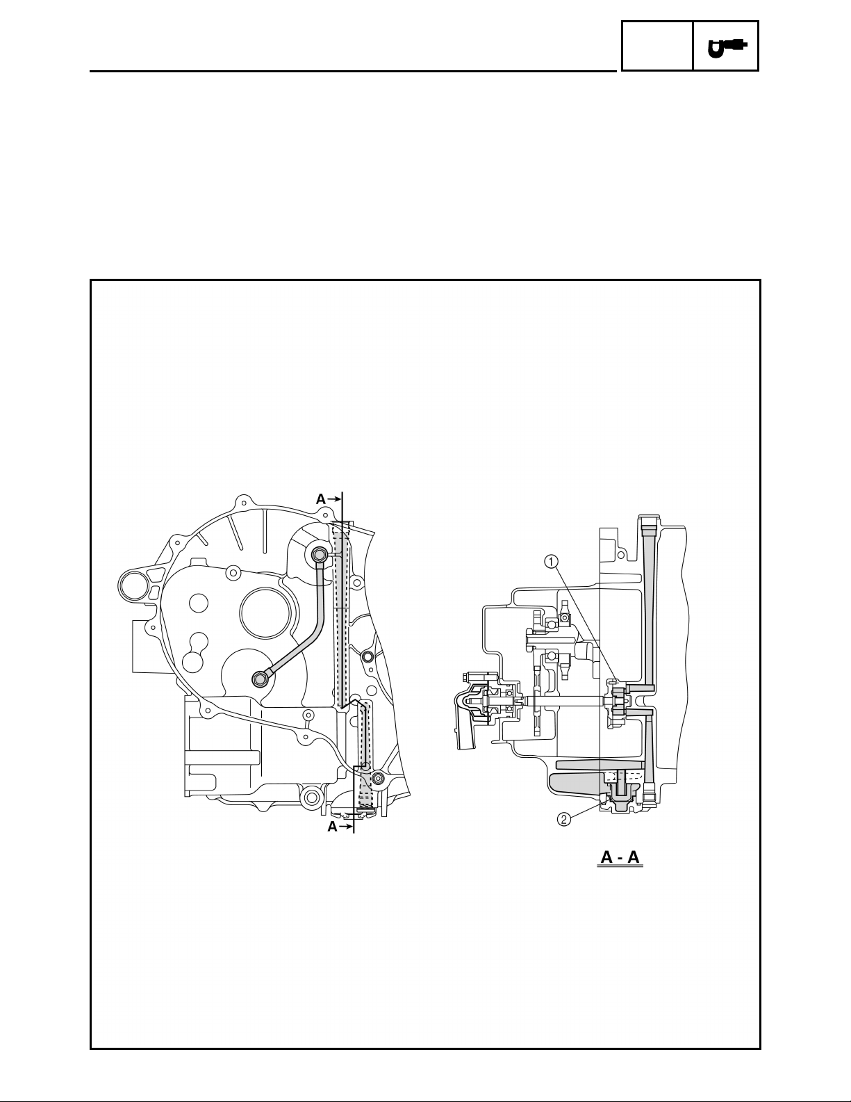
1 Oil pump
2 Oil strainer
OIL FLOW DIAGRAMS
SPEC
2 - 26
Page 52
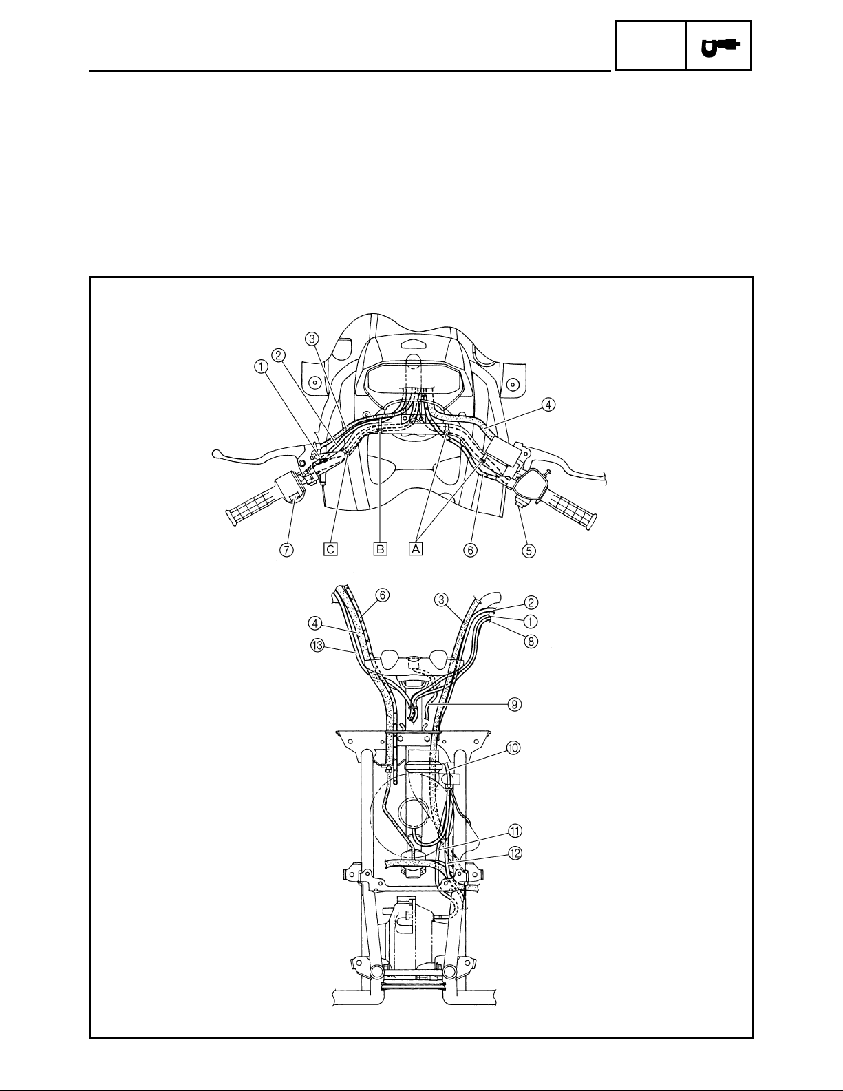
CABLE ROUTING
1 Rear brake switch lead
2 Starter cable
3 Rear brake cable
4 Front brake hose
5 On-command four-wheel drive switch
6 Throttle cable
7 Handlebar switch
8 Handlebar switch lead
9 Main switch lead
CABLE ROUTING
0 Fan motor breather hose
A Differential gear case breather hose
B Sub-wire harness (to gear motor)
C On-command four-wheel drive switch lead
SPEC
2 - 27
Page 53

CABLE ROUTING
È Fasten the on-command four-wheel drive switch lead behind the handlebar with a plastic band.
É Fasten the starter cable, handlebar switch lead and rear brake switch lead behind the handlebar with a
plastic band.
Ê Fasten the handlebar switch lead and rear brake switch lead behind the handlebar with a plastic band.
SPEC
2 - 28
Page 54
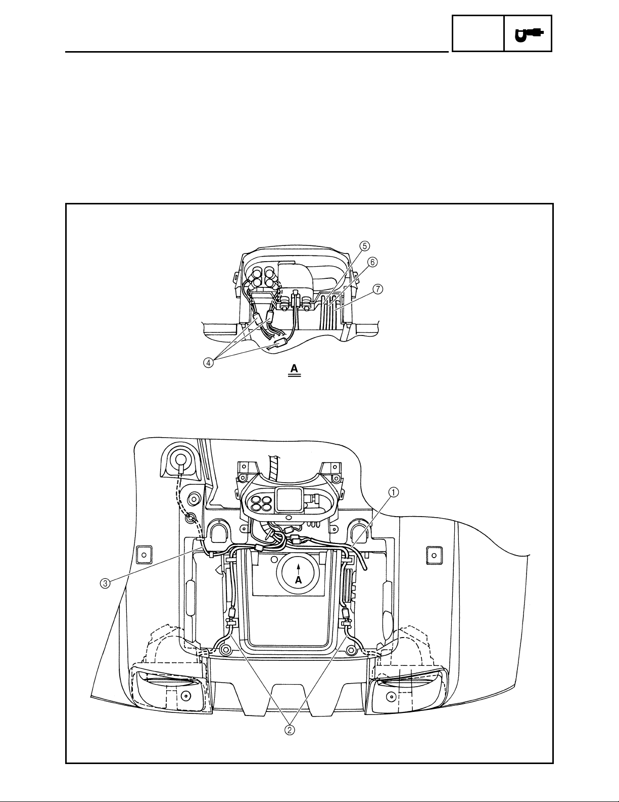
1 Sub-wire harness
2 Headlight lead
3 Auxiliary DC jack lead
4 Meter assembly coupler
5 Differential gear case breather hose
6 Coolant reservoir breather hose
7 Fan motor breather hose
CABLE ROUTING
SPEC
2 - 29
Page 55

CABLE ROUTING
SPEC
1 Starter cable
2 Cylinder head breather hose
3 Fuel hose
4 Carburetor drain hose
5 Rear brake lever cable
6 Coolant reservoir breather hose
7 Radiator outlet hose
8 Coolant reservoir hose
9 Sub-wire harness
0 Differential gear case breather hose
A Thermo switch (radiator)
B Speedometer cable
È Insert the fuel tank breather hose into the hole of
the handlebar cover.
É Fasten the sub-wire harness, differential gear
case breather hose, coolant reservoir hose,
coolant reservoir breather hose, thermo switch
(radiator) lead and fan motor breather hose with
a plastic band.
2 - 30
Page 56

CABLE ROUTING
SPEC
1 Cylinder head breather hose
2 Final drive gear case breather hose
3 Rear brake breather hose
4 Wire harness
5 Starter motor lead
6 Negative battery lead
7 Rear brake lever cable
8 Air filter case check hose
9 Water pump breather hose
0 Radiator outlet hose
A Starter cable
B Float chamber air vent hose
C Cylinder head breather hose
D Fuel hose
E A.C. magneto lead
F Gear position switch lead
G Neutral switch
H Reverse switch
I Rectifier/regulator
2 - 31
Page 57
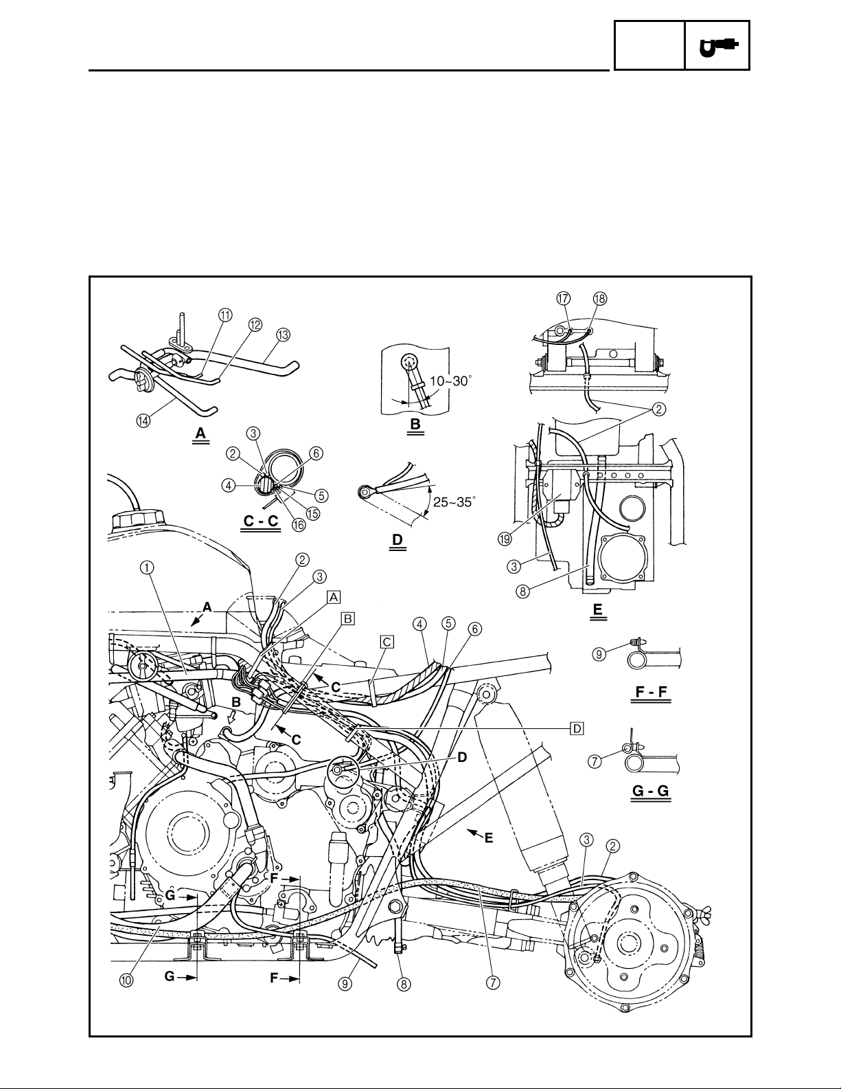
CABLE ROUTING
È Fasten the wire harness with a plastic band.
É Fasten the starter motor lead, wire harness, negative battery lead, final drive gear case breather hose, rear
brake breather hose, rectifier/regulator lead, gear position switch lead and A.C. magneto lead with a plastic
band.
Ê Fasten the wire harness, starter motor lead with a plastic band.
Ë Fasten the gear position switch lead, A.C. magneto lead, rectifier/regulator lead and negative battery lead
with a plastic band.
SPEC
2 - 32
Page 58

CABLE ROUTING
SPEC
1 Throttle cable
2 Radiator inlet hose
3 Spark plug lead
4 Main switch
5 Wire harness
6 Rear brake light switch lead
7 Select lever control cable
8 Rear brake pedal cable
È Fasten the radiator inlet hose and spark plug
lead with a plastic band.
2 - 33
Page 59

1 Front brake hose
2 Float chamber air vent hose
3 Throttle cable
4 Wire harness
5 Final drive gear case breather hose
6 Rear brake breather hose
7 Starter cable
8 Rear brake lever cable
CABLE ROUTING
SPEC
2 - 34
Page 60

1 Battery
2 Negative battery lead
3 Tail/brake light lead
4 CDI unit
5 Positive battery lead
CABLE ROUTING
SPEC
2 - 35
Page 61

1 Rear brake pedal cable
2 Final drive gear case breather hose
3 Rear brake breather hose
4 Rear brake lever cable
5 Air filter case check hose
CABLE ROUTING
SPEC
2 - 36
Page 62

INTRODUCTION/
PERIODIC MAINTENANCE/LUBRICATION
EB300000
CHK
ADJ
PERIODIC CHECKS AND ADJUSTMENTS
INTRODUCTION
This chapter includes all information necessary to perform recommended checks and adjustments.
These preventive maintenance procedures, if followed, will ensure more reliable vehicle operation
and a longer service life. The need for costly overhaul work will be greatly reduced. This information
applies to vehicles already in service as well as to new vehicles that are being prepared for sale. All
service technicians should be familiar with this entire chapter.
PERIODIC MAINTENANCE/LUBRICATION
INITIAL EVERY
ITEM ROUTINE
Valves*
Cooling system
Spark plug
Air filter element
Carburetor*
Crankcase breather
system*
Exhaust system*
Spark arrester
Fuel line*
Engine oil
Engine oil filter
cartridge
Engine oil strainer*
Final gear oil
Differential gear oil
Front brake*
Rear brake
V-belt*
Wheels*
Wheel bearing*
• Check valve clearance.
• Adjust if necessary.
• Check coolant leakage.
• Repair if necessary.
• Replace coolant every 24 months.
• Check condition.
• Adjust gap and clean.
• Replace if necessary.
• Clean.
• Replace if necessary.
• Check and adjust idle speed/starter operation.
• Adjust if necessary.
• Check breather hose for cracks or damage.
• Replace if necessary.
• Check for leakage.
• Tighten if necessary.
• Replace gasket(s) if necessary.
• Clean.
• Check fuel hose for cracks or damage.
• Replace if necessary.
• Replace. (Warm engine before draining.)
• Replace.
• Clean.
• Check for oil leakage.
• Replace every 12 months.
• Check operation/fluid leakage. (See NOTE page 3-2.)
• Correct if necessary.
• Check operation.
• Adjust if necessary.
• Check operation.
• Check for cracks or damage.
• Check balance/damage/runout.
• Repair if necessary.
• Check bearing assemblies for looseness/damage.
• Replace if damaged.
1
month3 months6 months6 months1 year
Every 20–40 hours
(More often in wet or dusty areas.)
3
3 - 1
Page 63

CHK
PERIODIC MAINTENANCE/LUBRICATION
INITIAL EVERY
ITEM ROUTINE
Front and rear
suspension*
Steering system*
Axle boots*
Fittings and
fasteners*
• Check operation.
• Correct if necessary.
• Check operation./Replace if damaged.
• Check toe-in./Adjust if necessary.
• Check operation.
• Replace if damaged.
• Check all chassis fittings and fasteners.
• Correct if necessary.
* It is recommended that these items be serviced by a Yamaha dealer.
OTE:
●
Recommended brake fluid: DOT 4
●
Brake fluid replacement:
1.When disassembling the master cylinder or caliper, replace the brake fluid. Normally check the
brake fluid level and add fluid as required.
2.On the inner parts of the master cylinder and caliper, replace the oil seals every two years.
3.Replace the brake hoses every four years, or if cracked or damaged.
1
month3 months6 months6 months1 year
ADJ
WARNING
Indicates a potential hazard that could result in serious injury or death.
3 - 2
Page 64

SEAT, CARRIERS, FENDERS AND FUEL TANK
SEAT, CARRIERS, FENDERS AND FUEL TANK
SEAT AND SIDE PANELS
CHK
ADJ
Order Job name/Part name Q’ty Remarks
Removing the seat and side panels
1Seat 1
2 Fuel tank side panel (left) 1
3 Fuel tank side panel (right) 1
4 Engine side panel 1
5 Engine side cover 1
Remove the parts in the order below.
OTE:
Pull up the seat lock lever, then pull up on
the rear of the seat.
For installation, reverse the removal
procedure.
3 - 3
Page 65
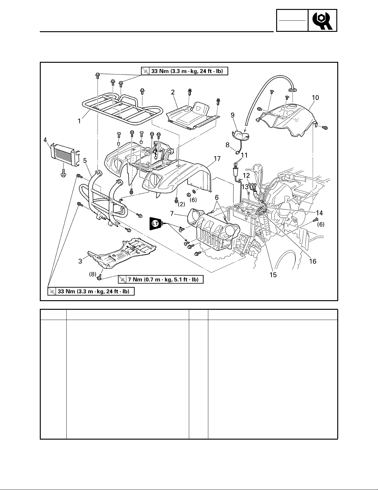
SEAT, CARRIERS, FENDERS AND FUEL TANK
FRONT CARRIER, FRONT BUMPER AND FRONT FENDER
CHK
ADJ
Order Job name/Part name Q’ty Remarks
Removing the front carrier, front
bumper and front fender
Seat and fuel tank side panels Refer to “SEAT AND SIDE PANELS”.
1 Front carrier 1
2 Front fender panel 1
3 Engine skid plate 1
4 Front bumper cover 1
5 Front bumper 1
6 Headlight coupler 2 Disconnect.
7 Front grill 1
8 Main switch coupler 1 Disconnect.
9 Handlebar cover 1
10 Fuel tank cover 1
Remove the parts in the order below.
3 - 4
Page 66

SEAT, CARRIERS, FENDERS AND FUEL TANK
CHK
ADJ
Order Job name/Part name Q’ty Remarks
11 Auxiliary DC jack connector 2 Disconnect.
12 Meter assembly coupler 3 Disconnect.
13 Speedometer cable 1 Disconnect.
14 Coolant reservoir breather hose 1
15 Fan motor breather hose 1
16 Differential gear case breather hose 1
17 Front fender 1
For installation, reverse the removal
procedure.
3 - 5
Page 67

SEAT, CARRIERS, FENDERS AND FUEL TANK
REAR CARRIER AND REAR FENDER
CHK
ADJ
Order Job name/Part name Q’ty Remarks
Removing the rear carrier and rear
fender
Seat and fuel tank side panels Refer to “SEAT AND SIDE PANELS”.
Fuel tank Refer to “FUEL TANK”.
1 Rear carrier 1
2 Battery holding bracket 1
3 Battery lead cover 1
4 Battery lead 2 Disconnect.
Remove the parts in the order below.
CAUTION:
First disconnect the negative lead,
then disconnect the positive lead.
5 Battery
6 Starter relay ground lead 1 Disconnect.
7 Tail/brake light connector 3 Disconnect.
3 - 6
Page 68
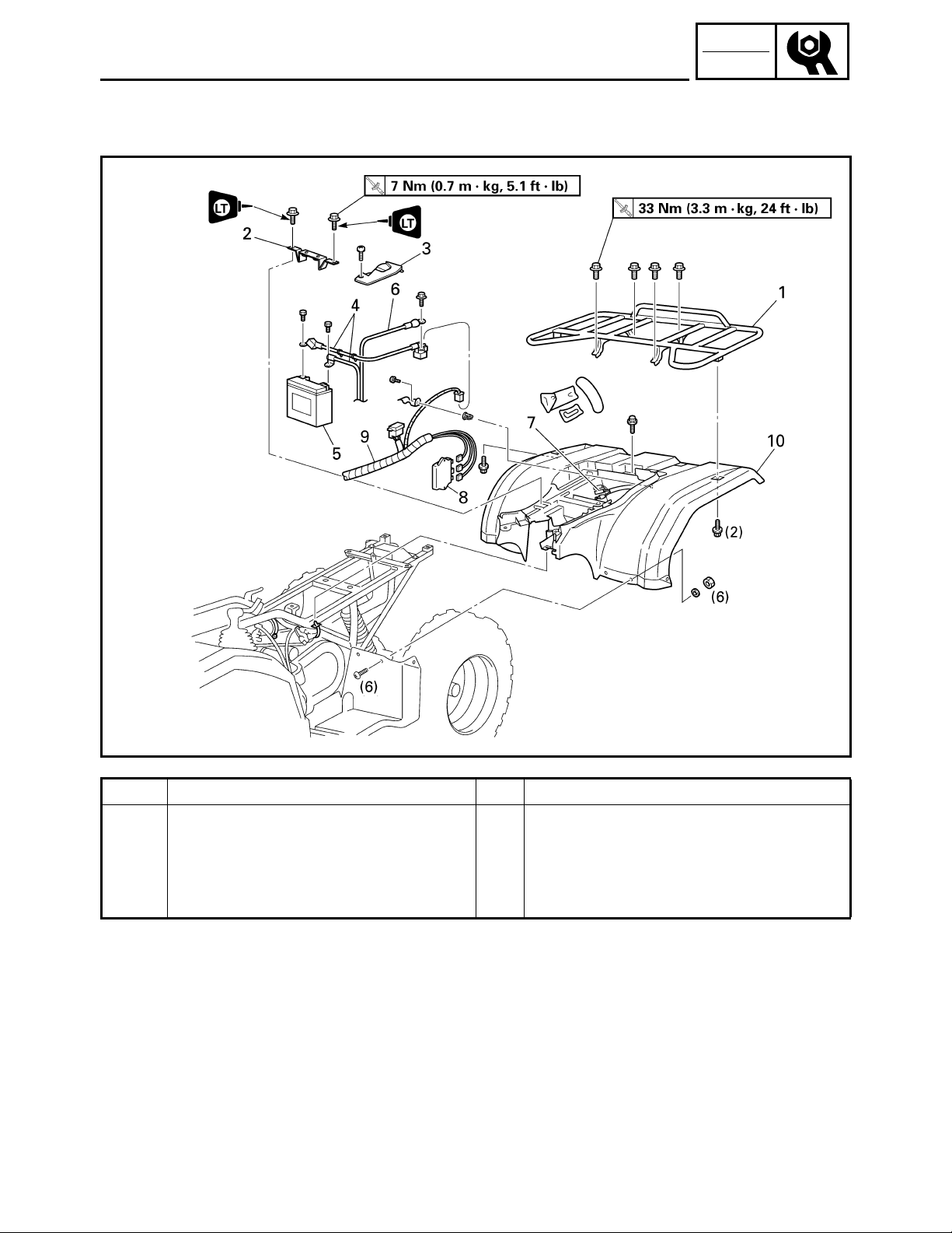
SEAT, CARRIERS, FENDERS AND FUEL TANK
CHK
ADJ
Order Job name/Part name Q’ty Remarks
8 C.D.I. unit 1
9 Wire harness 1
10 Rear fender 1
For installation, reverse the removal
procedure.
3 - 7
Page 69
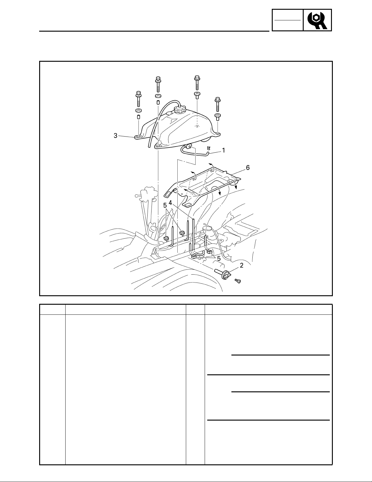
FUEL TANK
SEAT, CARRIERS, FENDERS AND FUEL TANK
CHK
ADJ
Order Job name/Part name Q’ty Remarks
Removing the fuel tank
Seat and fuel tank side panels Refer to “SEAT AND SIDE PANELS”.
Fuel tank cover Refer to “FRONT CARRIER, FRONT
1 Fuel hose 1
2 Fuel cock lever 1
3 Fuel tank 1
4 Float chamber air vent hose 1
5 Plastic band 4
6 Rubber cover 1
Remove the parts in the order below.
BUMPER AND FRONT FENDER”.
OTE:
Before disconnecting the fuel hose, turn
the fuel cock to “OFF”.
OTE:
When installing the fuel tank, pass the
fuel tank breather hose through the hole
of the handlebar protector.
For installation, reverse the removal
procedure.
3 - 8
Page 70
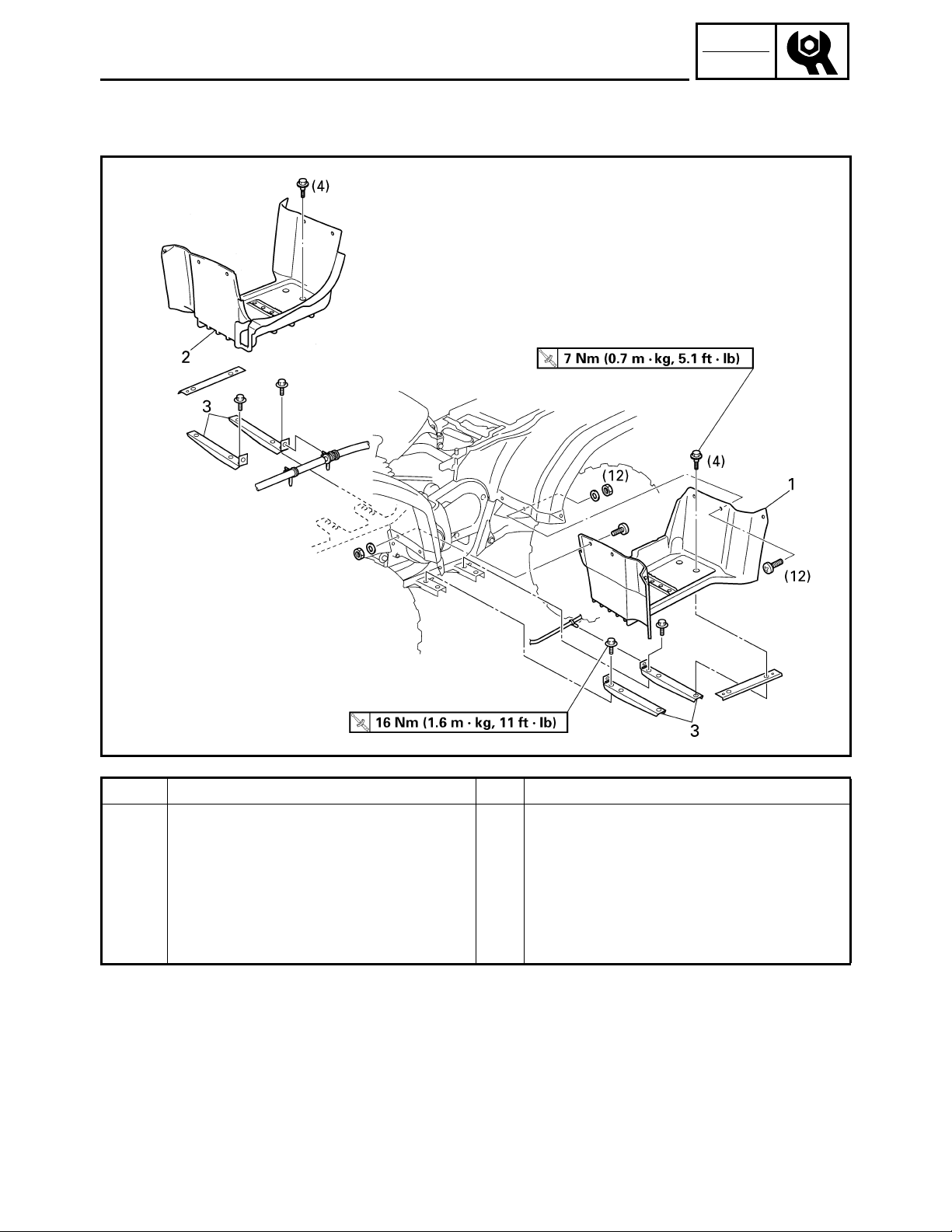
FOOTREST BOARDS
FOOTREST BOARDS
CHK
ADJ
Order Job name/Part name Q’ty Remarks
Removing the footrest boards
Fuel tank side panels Refer to “SEAT AND SIDE PANELS”.
1 Left footrest board 1
2 Right footrest board 1
3 Footrest bracket 4
Remove the parts in the order below.
For installation, reverse the removal
procedure.
3 - 9
Page 71
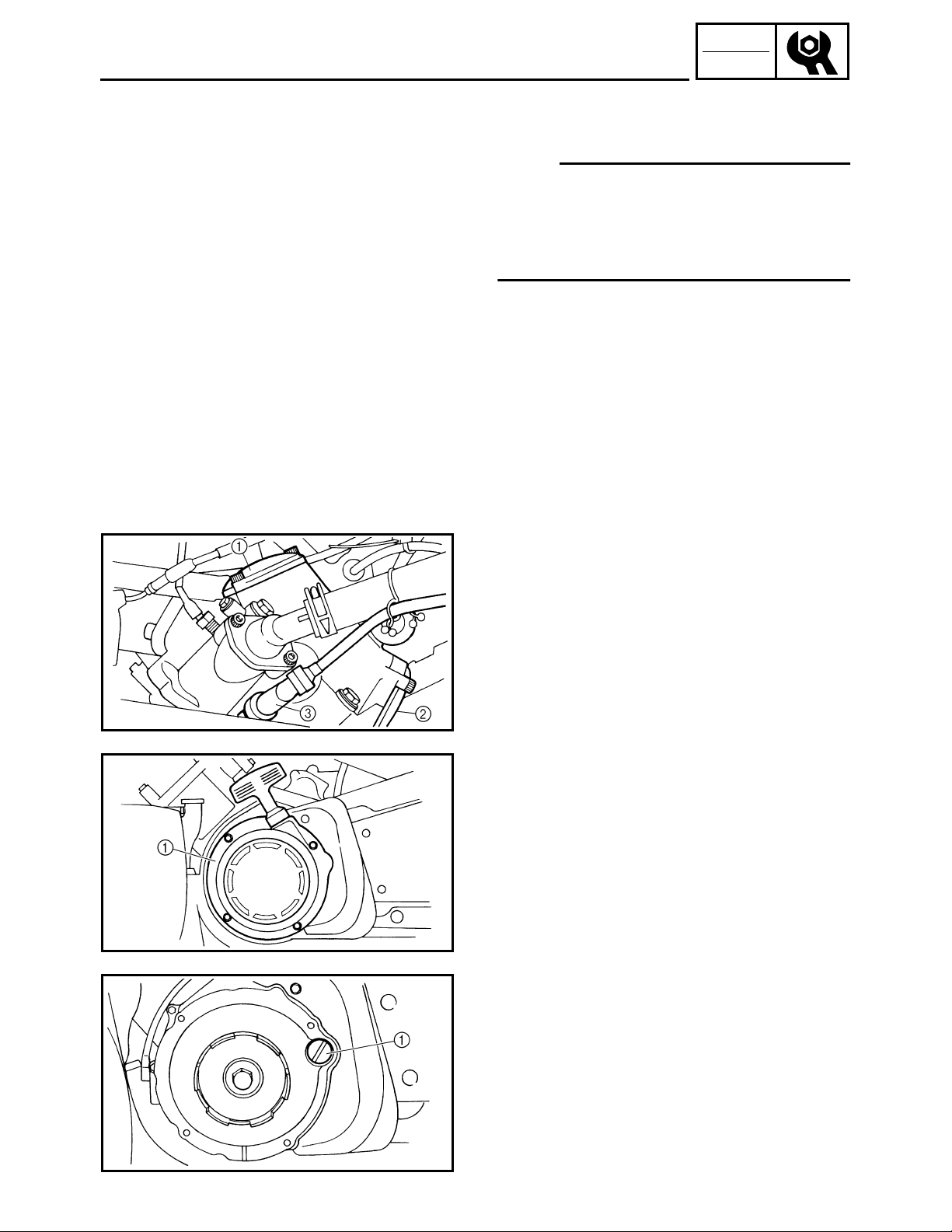
ADJUSTING THE VALVE CLEARANCE
ENGINE
ADJUSTING THE VALVE CLEARANCE
OTE:
●
The valve clearance must be adjusted when
the engine is cool to the touch.
●
Adjust the valve clearance when the piston is
at the Top Dead Center (T.D.C.) on the
compression stroke.
1.Remove:
●
Seat
●
Front carrier
●
Front fender
●
Fuel tank
Refer to “SEAT, CARRIERS, FENDERS
AND FUEL TANK”.
CHK
ADJ
2.Remove:
●
Tappet cover (intake) 1
●
Tappet cover (exhaust) 2
3.Disconnect:
●
Spark plug cap 3
4.Remove:
●
Spark plug
5.Remove:
●
Recoil starter 1
6.Remove:
●
Timing plug 1
3 - 10
Page 72
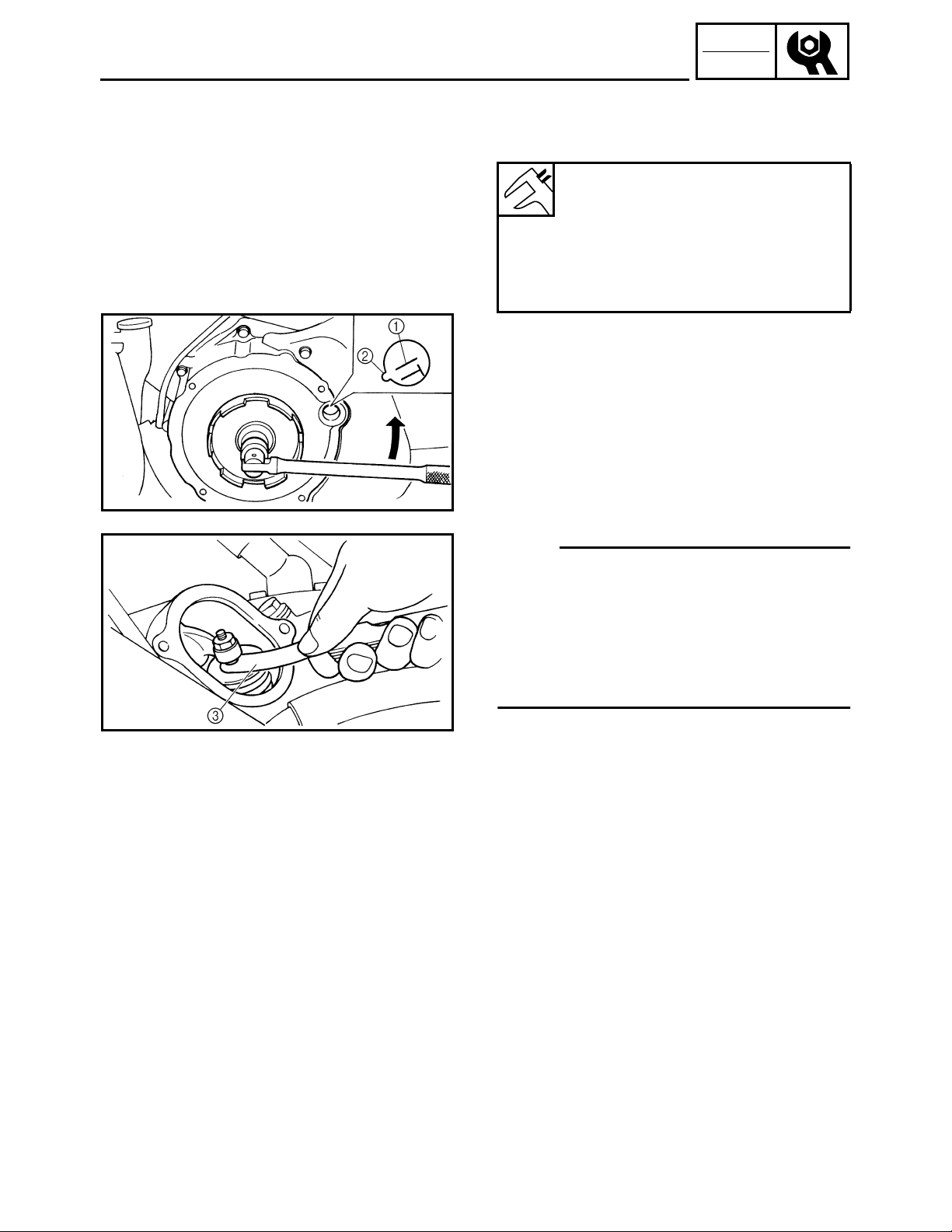
ADJUSTING THE VALVE CLEARANCE
7.Check:
●
Valve clearance
Out of specification → Adjust.
Valve clearance (cold):
Intake:
0.06 ~ 0.10 mm
(0.0024 ~ 0.0039 in)
Exhaust:
0.16 ~ 0.20 mm
(0.0063 ~ 0.0079 in)
*****************************************************
Checking steps:
●
Turn the crankshaft counterclockwise with a
wrench.
●
Align the “T” mark 1 on the rotor with the
stationary pointer 2 on the crankcase cover.
When the “T” mark is aligned with the
stationary pointer, the piston is at the Top
Dead Center (T.D.C.).
CHK
ADJ
OTE:
●
When the piston is at the Top Dead Center
(T.D.C.) on the compression stroke, there
should be clearance between the valve stem
tips and their respective rocker arm adjusting
screws.
●
If there is no clearance, rotate the crankshaft
counterclockwise one turn.
●
Measure the valve clearance using a feeler
gauge 3.
*****************************************************
3 - 11
Page 73
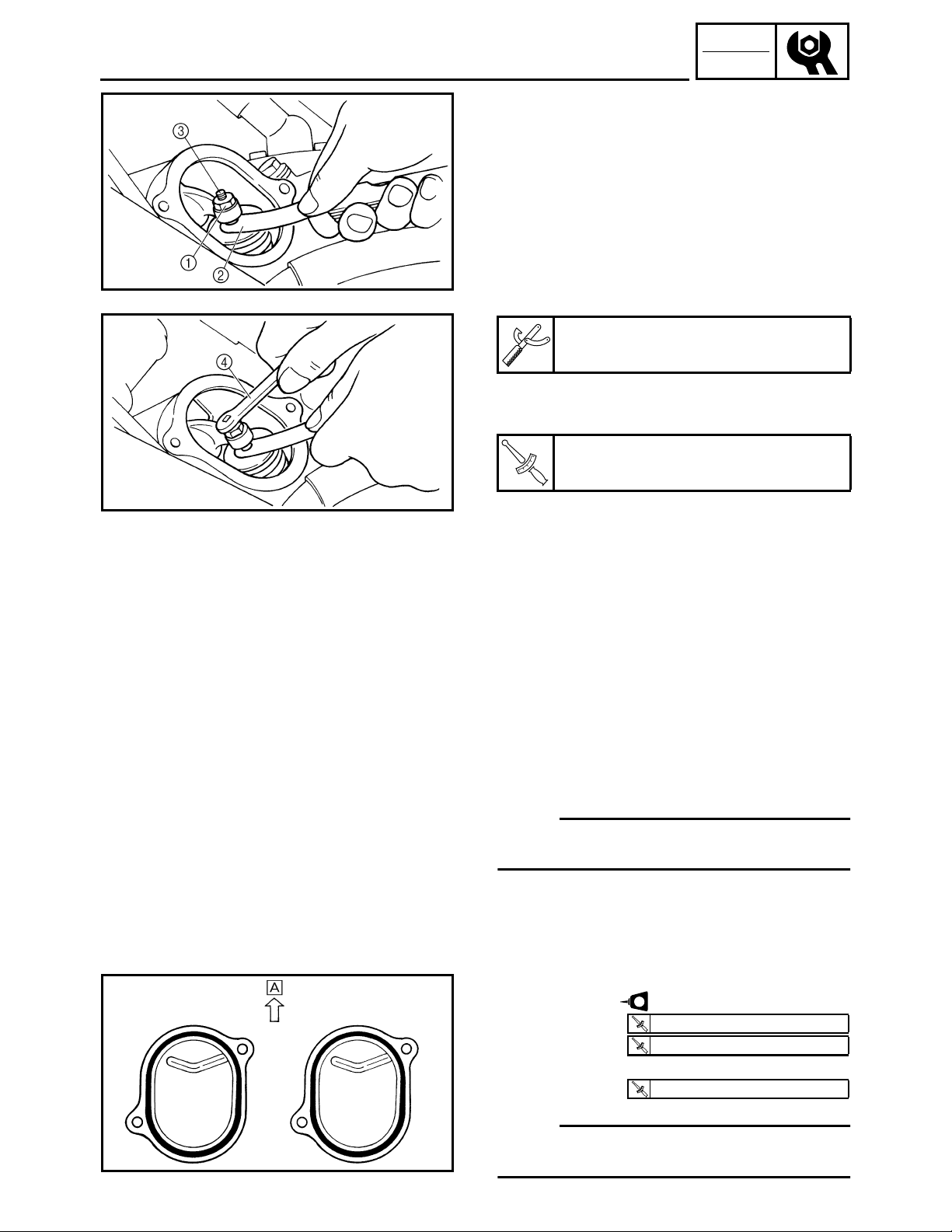
ADJUSTING THE VALVE CLEARANCE
8.Adjust:
●
Valve clearance
*****************************************************
Adjustment steps:
●
Loosen the locknut 1.
●
Insert a feeler gauge 2 between the adjuster
end and the valve end.
●
Turn the adjuster 3 clockwise or
counterclockwise with the valve adjusting
tool 4 until the proper clearance is obtained.
Tappet adjusting tool:
P/N. YM-08035, 90890-01311
●
Hold the adjuster to prevent it from moving,
and then tighten the locknut.
Locknut:
T
20 Nm (2.0 m • kg, 14 ft • lb)
.
R
.
CHK
ADJ
●
Measure the valve clearance.
●
If the clearance is incorrect, repeat the above
steps until the proper clearance is obtained.
*****************************************************
9.Install:
●
All removed parts
OTE:
Install all removed parts in the reverse order of
their disassembly. Note the following points.
3 - 12
10.Install:
●
Recoil starter
●
Spark plug
●
Tappet covers
LT
T
10 Nm (1.0 m • kg, 7.2 ft • lb)
.
R
.
T
18 Nm (1.8 m • kg, 13 ft • lb)
.
R
.
T
10 Nm (1.0 m • kg, 7.2 ft • lb)
.
R
.
OTE:
Install the tappet covers with the ridge facing
up È.
Page 74

ADJUSTING THE VALVE CLEARANCE/
ADJUSTING THE IDLING SPEED
11.Install:
●
Fuel tank
●
Front fender
●
Front carrier
●
Seat
Refer to “SEAT, CARRIERS, FENDERS
AND FUEL TANK”.
CHK
ADJ
ADJUSTING THE IDLING SPEED
1.Start the engine and let it warm up for
several minutes.
2.Remove:
●
Seat
●
Fuel tank side panels
Refer to “SEAT, CARRIERS, FENDERS
AND FUEL TANK”.
3.Attach:
●
Inductive self-powered tachometer or engine
tachometer
(to the spark plug lead)
Inductive self-powered tachometer:
P/N. YU-8036-B
Engine tachometer:
P/N. 90890-03113
4.Check:
●
Engine idling speed
Out of specification → Adjust.
3 - 13
Engine idling speed:
1,450 ~ 1,550 r/min
Page 75

ADJUSTING THE IDLING SPEED/
ADJUSTING THE THROTTLE LEVER FREE PLAY
5.Adjust:
●
Engine idling speed
*****************************************************
Adjustment steps:
●
Turn the throttle stop screw 1 in or out until
the specified idling speed is obtained.
CHK
ADJ
Turning in
Turning out
Idling speed becomes
higher.
Idling speed becomes
lower.
*****************************************************
6.Detach:
●
Inductive or engine tachometer
7.Adjust:
●
Throttle lever free play
Refer to “ADJUSTING THE THROTTLE
LEVER FREE PLAY”.
Throttle lever free play:
3 ~ 5 mm (0.12 ~ 0.20 in)
8.Install:
●
Fuel tank side panels
●
Seat
Refer to “SEAT, CARRIERS, FENDERS
AND FUEL TANK”.
3 - 14
ADJUSTING THE THROTTLE LEVER FREE
PLAY
OTE:
Engine idling speed should be adjusted
properly before adjusting the throttle lever free
play.
Page 76

ADJUSTING THE THROTTLE LEVER FREE PLAY
1.Check:
●
Throttle lever free play a
Out of specification → Adjust.
Throttle lever free play:
3 ~ 5 mm (0.12 ~ 0.20 in)
2.Remove:
●
Seat
●
Fuel tank side panel (right)
Refer to “SEAT, CARRIERS, FENDERS
AND FUEL TANK”.
CHK
ADJ
3.Adjust:
●
Throttle lever free play
*****************************************************
Adjustment steps:
First step:
●
Pull back the adjuster cover 1.
●
Loosen the locknut 2 on the carburetor side.
●
Turn the adjuster 3 in or out until the correct
free play is obtained.
Turning in Free play is increased.
Turning out Free play is decreased.
●
Tighten the locknut 2.
●
Push in the adjuster cover 1.
OTE:
If the free play cannot be adjusted here, adjust
it at the throttle lever side of the cable.
3 - 15
Page 77

ADJUSTING THE THROTTLE LEVER FREE PLAY/
ADJUSTING THE SPEED LIMITER
Second step:
●
Pull back the adjuster cover 4.
●
Loosen the locknut 5.
●
Turn the adjuster 6 in or out until the correct
free play is obtained.
Turning in Free play is increased.
Turning out Free play is decreased.
●
Tighten the locknut 5.
●
Push in the adjuster cover 4.
WARNING
After adjusting the free play, turn the
handlebar to the right and left to make sure
that the engine idling speed does not
increase.
*****************************************************
CHK
ADJ
4.Install:
●
Fuel tank side panel (right)
●
Seat
Refer to “SEAT, CARRIERS, FENDERS
AND FUEL TANK”.
ADJUSTING THE SPEED LIMITER
The speed limiter keeps the carburetor throttle
from becoming fully-opened even when the
throttle lever is applied to the maximum
position. Screwing in the adjuster stops the
engine speed from increasing.
1.Check:
●
Speed limiter length a
Out of specification → Adjust.
3 - 16
Speed limiter length:
12 mm (0.47 in)
Page 78

ADJUSTING THE SPEED LIMITER/
ADJUSTING THE STARTER CABLE
2.Adjust:
●
Speed limiter length
*****************************************************
Speed limiter length adjustment steps:
●
Loosen the locknut 1.
●
Turn the adjuster 2 in or out until the
specified speed limiter length is obtained.
CHK
ADJ
Turning in
Turning out
●
Tighten the locknut.
Speed limiter length is
decreased.
Speed limiter length is
increased.
WARNING
Particularly for a beginner rider, the
●
speed limiter should be screwed in
completely. Screw it out little by little as
their riding technique improves. Never
remove the speed limiter for a beginning
rider.
For proper throttle lever operation do not
●
turn out the adjuster more than 12 mm
(0.47 in). Also, always adjust the throttle
lever free play to 3 ~ 5 mm (0.12 ~ 0.20 in).
*****************************************************
3 - 17
ADJUSTING THE STARTER CABLE
1.Remove:
●
Seat
●
Fuel tank side panel (left)
Refer to “SEAT, CARRIERS, FENDERS
AND FUEL TANK”.
Page 79

ADJUSTING THE STARTER CABLE
2.Adjust:
*****************************************************
Adjustment steps:
●
Disconnect the starter cable 1 from the
carburetor body.
OTE:
Do not remove the starter plunger 2 from the
starter cable.
●
Measure the starter plunger stroke distance
a of the starter lever 3 fully close to fully
open position. If the distance is out of
specification adjust it as described below.
Starter plunger stroke distance:
15 mm (0.59 in)
Fully closed position
È
Fully open position
É
●
Pull back the boot 4.
●
Loosen the locknut 5.
●
Turn the adjuster 6 in or out until the correct
free play is obtained.
CHK
ADJ
Turning in Free play increased.
Turning out Free play decreased.
●
Tighten the locknut 5.
●
Push in the boot 4.
●
Connect the starter cable to the carburetor.
WARNING
After adjusting the cable, turn the
handlebar to right and left, and make sure
that the engine idling speed does not
increase.
*****************************************************
3.Install:
●
Fuel tank side panel (left)
●
Seat
Refer to “SEAT, CARRIERS, FENDERS
AND FUEL TANK”.
3 - 18
Page 80
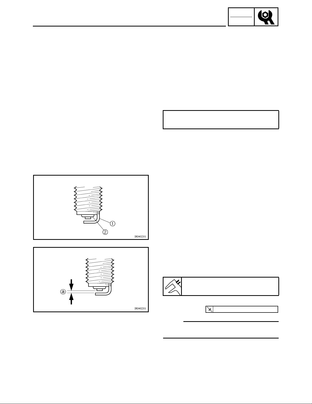
CHECKING THE SPARK PLUG
CHECKING THE SPARK PLUG
1.Remove:
●
Seat
●
Fuel tank side panel (right)
Refer to “SEAT, CARRIERS, FENDERS
AND FUEL TANK”.
2.Remove:
●
Spark plug
3.Check:
●
Spark plug type
Incorrect → Replace.
Standard spark plug:
DR8EA/NGK
CHK
ADJ
4.Check:
●
Electrode 1
Wear/damage → Replace.
●
Insulator 2
Abnormal color → Replace.
Normal color is a medium-to-light tan color.
5.Clean the spark plug with a spark plug
cleaner or wire brush.
6.Measure:
●
Plug gap a
Use a wire gauge or feeler gauge.
Out of specification → Regap.
Spark plug gap:
0.6 ~ 0.7 mm (0.024 ~ 0.028 in)
7.Tighten:
T
18 Nm (1.8 m • kg, 13 ft • lb)
.
●
Spark plug
R
.
OTE:
Before installing a spark plug, clean the gasket
surface and plug surface.
3 - 19
8.Install:
●
Fuel tank side panel (right)
●
Seat
Refer to “SEAT, CARRIERS, FENDERS
AND FUEL TANK”.
Page 81

CHECKING THE IGNITION TIMING
CHECKING THE IGNITION TIMING
OTE:
Engine idling speed and throttle cable free play
should be adjusted properly before checking
the ignition timing.
1.Remove:
●
Seat
●
Fuel tank side panel (right)
Refer to “SEAT, CARRIERS, FENDERS
AND FUEL TANK”.
2.Attach:
●
Inductive self-powered tachometer or engine
tachometer
●
Timing light
(to spark plug lead)
Inductive self-powered tachometer:
P/N. YU-8036-B
Engine tachometer:
P/N. 90890-03113
Timing light:
P/N. YM-33277-A, 90890-03141
CHK
ADJ
3.Check:
●
Ignition timing
*****************************************************
Checking steps:
●
Warm up the engine and keep it at the
specified speed.
Engine speed:
1,450 ~ 1,550 r/min
●
Remove the recoil starter 1.
●
Remove the timing plug 2.
●
Visually check the stationary pointer 3 to
verify it is within the required firing range 4
indicated on the flywheel.
Incorrect firing range → Check the pickup
coil.
●
Install the timing plug.
●
Install the recoil starter.
Recoil starter bolt:
T
10 Nm (1.0 m • kg, 7.2 ft • Ib)
.
R
.
LOCTITE
®
3 - 20
*****************************************************
Page 82
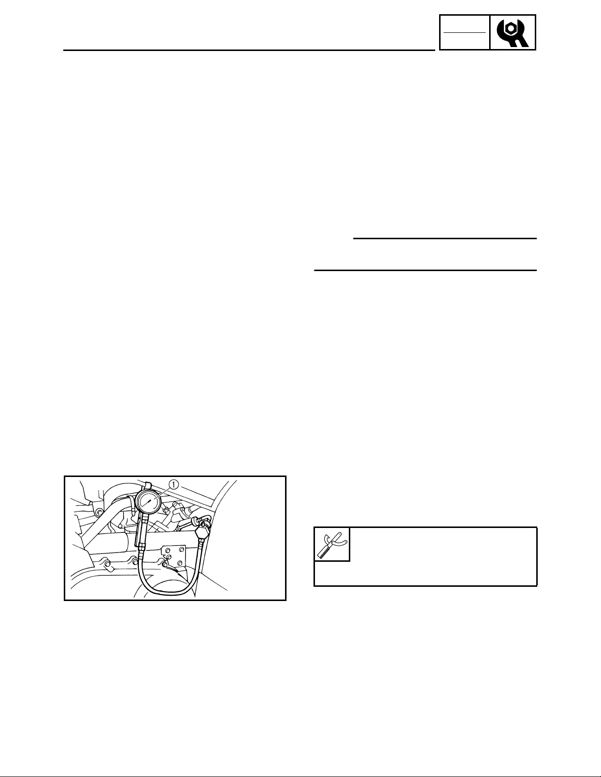
CHECKING THE IGNITION TIMING/
MEASURING THE COMPRESSION PRESSURE
4.Detach:
●
Timing light
●
Inductive self-powered tachometer or engine
tachometer
5.Install:
●
Seat
●
Fuel tank side panel (right)
Refer to “SEAT, CARRIERS, FENDERS
AND FUEL TANK”.
MEASURING THE COMPRESSION
PRESSURE
OTE:
Insufficient compression pressure will result in
a loss of performance.
1.Check:
●
Valve clearance
Out of specification → Adjust.
Refer to “ADJUSTING THE VALVE
CLEARANCE”.
2.Start the engine and let it warm up for
several minutes.
3.Stop the engine.
4.Remove:
●
Seat
●
Fuel tank side panel (right)
Refer to “SEAT, CARRIERS, FENDERS
AND FUEL TANK”.
5.Remove:
●
Spark plug
6.Attach:
●
Adapter
●
Compression gauge 1
CHK
ADJ
3 - 21
Compression gauge:
P/N. YU-33223, 90890-03081
Adapter:
P/N. YU-33223-3, 90890-04082
Page 83
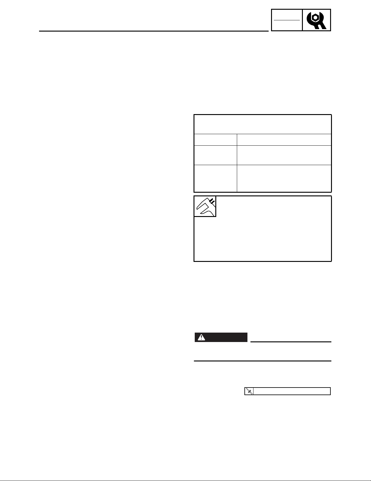
MEASURING THE COMPRESSION PRESSURE
7.Measure:
●
Compression pressure
Above the maximum pressure:
Check the cylinder head, valve surfaces, and
piston crown for carbon deposits.
Below the minimum pressure:
Squirt a few drops of oil into the affected
cylinder and measure again.
●
Refer to the table below.
Compression pressure
(with oil introduced into cylinder)
Reading Diagnosis
CHK
ADJ
Higher than
without oil
Same as
without oil
Worn or damaged pistons
Defective ring(s), valves,
cylinder head gasket or
piston is possible.
Compression pressure
(at sea level):
Standard:
2
1,400 kPa (14 kg/cm
, 203 psi)
Minimum:
2
1,218 kPa (12.2 kg/cm
, 177 psi)
Maximum:
2
1,568 kPa (15.7 kg/cm
, 227 psi)
*****************************************************
Measurement steps:
●
Crank over the engine with the electric
starter (be sure the battery is fully charged)
with the throttle wide-open until the
compression reading on the gauge
stabilizes.
3 - 22
WARNING
When cranking the engine, ground the
spark plug lead to prevent sparking.
*****************************************************
8.Install:
T
18 Nm (1.8 m • kg, 13 ft • lb)
.
●
Spark plug
9.Remove:
●
Fuel tank side panel (right)
●
Seat
Refer to “SEAT, CARRIERS, FENDERS
AND FUEL TANK”.
R
.
Page 84
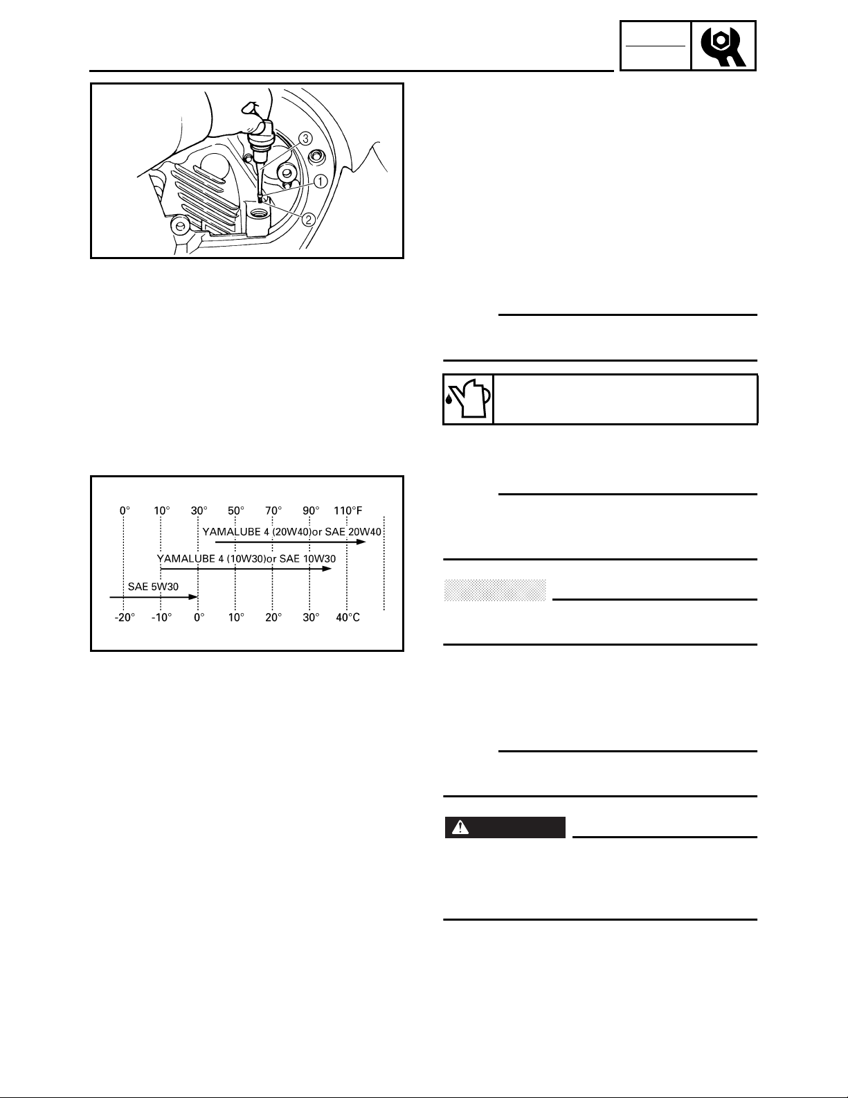
CHECKING THE ENGINE OIL LEVEL
CHECKING THE ENGINE OIL LEVEL
1.Place the machine on a level surface.
2.Remove:
●
Engine side panel
Refer to “SEAT, CARRIERS, FENDERS
AND FUEL TANK”.
3.Check:
●
Engine oil level
Oil level should be between the maximum
level mark 1 and minimum level mark 2.
Oil level low → Add oil to the proper level.
OTE:
Do not screw the dipstick 3 in when checking
the oil level.
Recommended oil:
Follow the left chart.
CHK
ADJ
OTE:
Recommended oil classification:
API Service “SE”, “SF” type or equivalent (e.g.
“SF–SE–CC”, “SF–SE–SD” etc.)
CAUTION:
Do not allow foreign material to enter the
crankcase.
4.Start the engine and let it warm up for
several minutes.
5.Stop the engine and check the oil level
again.
OTE:
Wait a few minutes until the oil settles before
checking the oil level.
WARNING
Never remove the dipstick just after high
speed operation because the heated oil
could spurt out. Wait until the oil cools
down before removing the dipstick.
3 - 23
6.Install:
●
Engine side panel
Refer to “SEAT, CARRIERS, FENDERS
AND FUEL TANK”.
Page 85
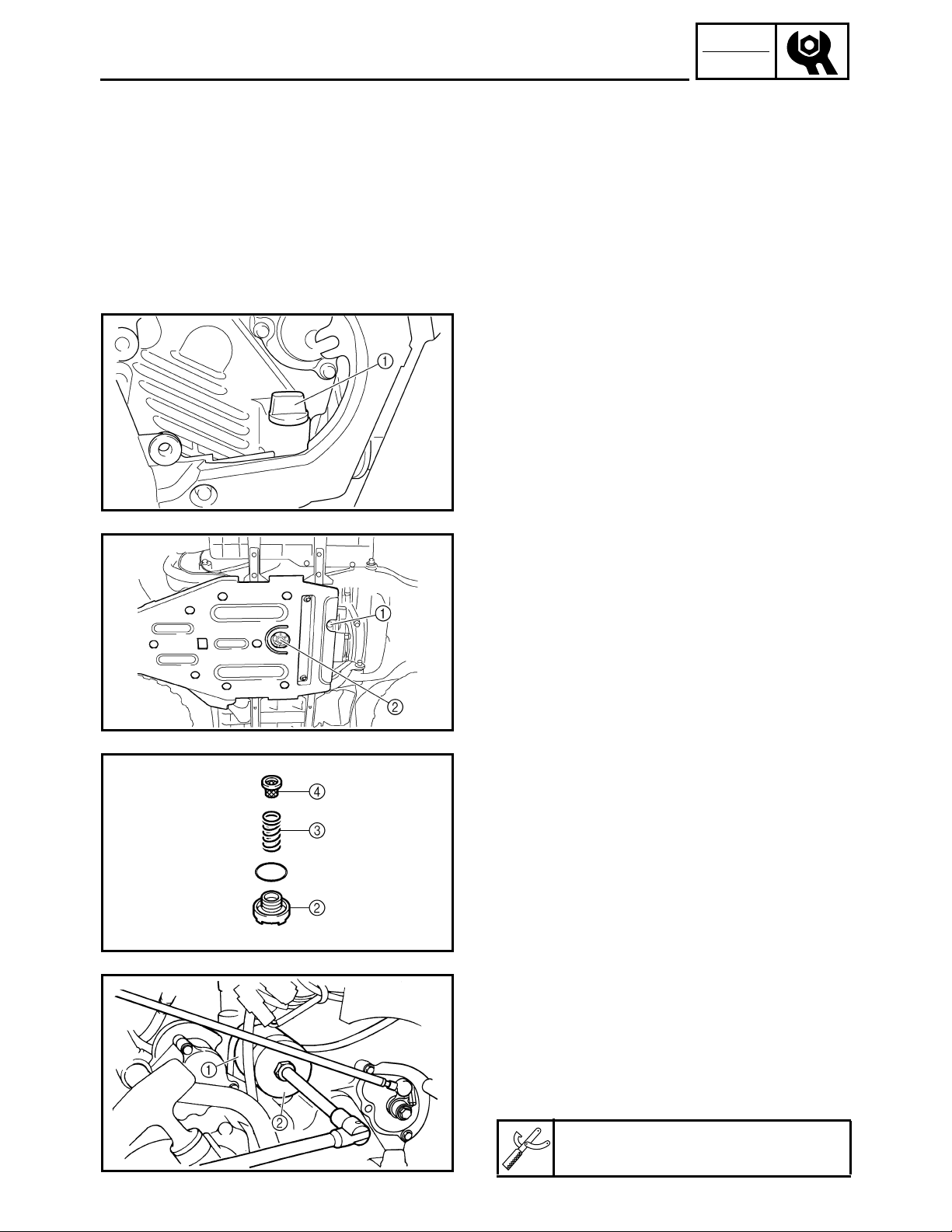
CHANGING THE ENGINE OIL
CHANGING THE ENGINE OIL
1.Start the engine and let it warm up for
several minutes.
2.Stop the engine and place an oil pan under
the engine.
3.Remove:
●
Seat
●
Fuel tank side panel (left)
●
Engine side cover
Refer to “SEAT, CARRIERS, FENDERS
AND FUEL TANK”.
4.Remove:
●
Engine oil filler plug (dipstick) 1
CHK
ADJ
5.Remove:
●
Engine oil drain bolt 1
Drain the engine oil.
●
Oil strainer cover 2
●
Compression spring 3
●
Oil strainer 4
6.Clean:
●
Oil strainer 4
7.If the oil filter cartridge is also to be replaced,
perform the following procedure.
3 - 24
*****************************************************
Replacement steps:
●
Remove the oil filter cartridge 1 with an oil
filter wrench 2.
Oil filter wrench:
P/N. YU-38411, 90890-01426
Page 86
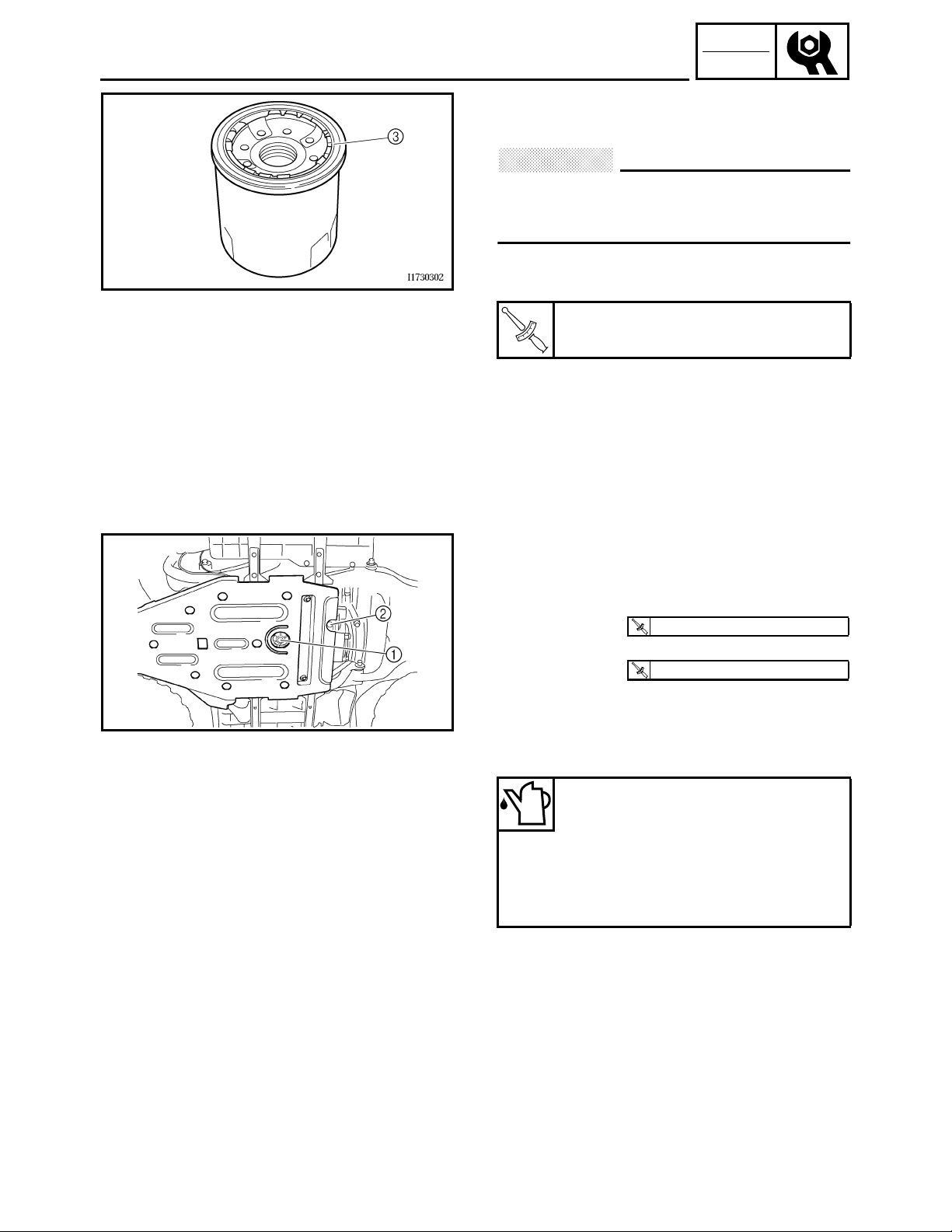
CHANGING THE ENGINE OIL
●
Lubricate the O-ring 3 of the new oil filter
cartridge with a thin coat of engine oil.
CAUTION:
Make sure that the O-ring 3 is positioned
correctly in the groove of the oil filter
cartridge.
●
Tighten the new oil filter cartridge to
specification with an oil filter wrench.
Oil filter cartridge:
T
*****************************************************
17 Nm (1.7 m • kg, 12 ft • lb)
.
R
.
CHK
ADJ
8.Install:
●
Oil strainer
●
Compression spring
●
Oil strainer cover 1
T
32 Nm (3.2 m • kg, 23 ft • lb)
.
R
.
●
Engine oil drain bolt 2
T
23 Nm (2.3 m • kg, 17 ft • lb)
.
R
.
9.Fill:
●
Crankcase
Refer to “CHECKING THE ENGINE OIL
LEVEL”.
Oil quantity:
Periodic oil change:
2.3 L (2.0 Imp qt, 2.4 US qt)
With oil filter replacement:
2.4 L (2.1 Imp qt, 2.5 US qt)
Total amount:
2.6 L (2.3 Imp qt, 2.7 US qt)
10.Install:
●
Engine oil filler plug
11.Warm up the engine for a few minutes, then
stop the engine.
12.Check:
●
Engine
(for engine oil leaks)
●
Oil level
Refer to “CHECKING THE ENGINE OIL
LEVEL”.
3 - 25
Page 87
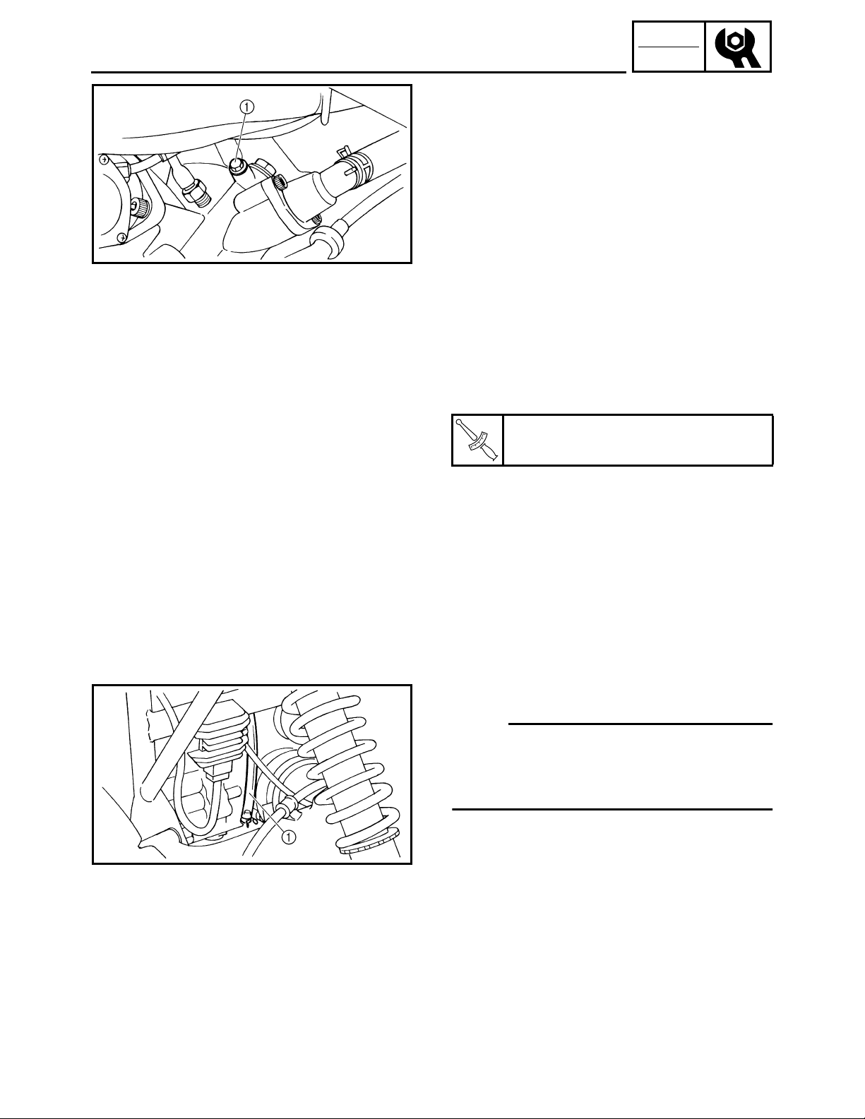
CHANGING THE ENGINE OIL/
CLEANING THE AIR FILTER
13.Check:
●
Engine oil pressure
*****************************************************
●
Slightly loosen the oil gallery bolt 1.
●
Start the engine and keep it idling until
engine oil starts to seep from the oil gallery
bolt. If no engine oil comes out after one
minute, turn the engine off so that it will not
seize.
●
Check the engine oil passages, the oil filter
cartridge and the oil pump for damage or
leakage. Refer to “CRANKCASE” in
CHAPTER 4.
●
Start the engine after solving the problem(s)
and check the engine oil pressure again.
●
Tighten the oil gallery bolt to specification.
Oil gallery bolt:
T
7 Nm (0.7 m • kg, 5.1 ft • lb)
.
R
.
CHK
ADJ
*****************************************************
14.Install:
●
Engine side cover
●
Fuel tank side panel (left)
●
Seat
Refer to “SEAT, CARRIERS, FENDERS
AND FUEL TANK”.
CLEANING THE AIR FILTER
OTE:
There is a check hose 1 at the bottom of the
air filter case. If dust and/or water collects in
this hose, clean the air filter element and air
filter case.
3 - 26
Page 88
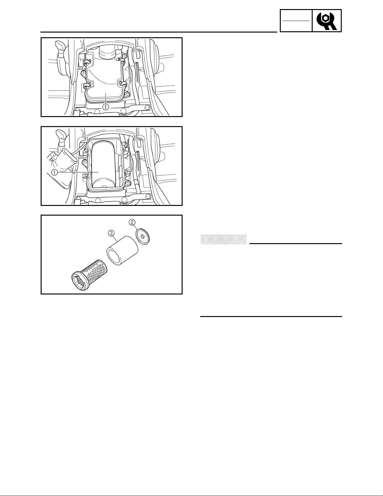
CLEANING THE AIR FILTER
1.Remove:
●
Seat
Refer to “SEAT, CARRIERS, FENDERS
AND FUEL TANK”.
2.Remove:
●
Air filter case cover 1
3.Remove:
●
Air filter element assembly 1
●
Air filter element cap
●
Air filter element
CHK
ADJ
Air filter element cap
2
Air filter element
3
CAUTION:
Never operate the engine with the air filter
element removed. This will allow unfiltered
air to enter, causing rapid wear and
possible engine damage. Additionally,
operation without the filter element will
affect carburetor tuning with subsequent
poor performance and possible engine
overheating.
4.Check:
●
Air filter element
Damaged → Replace.
3 - 27
Page 89
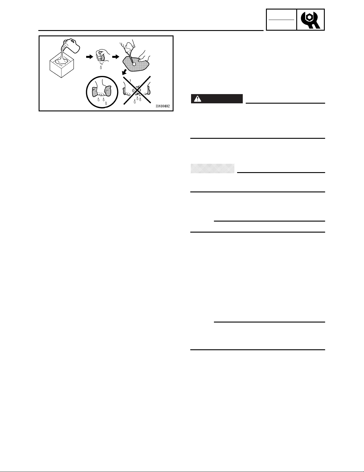
CLEANING THE AIR FILTER
5.Clean:
●
Air filter element
*****************************************************
Cleaning steps:
●
Wash the element gently, but thoroughly in
solvent.
WARNING
Use a cleaning solvent which is designed
to clean parts only. Never use gasoline or
low flash point solvents as they may cause
a fire or explosion.
●
Squeeze the excess solvent out of the
element and let it dry.
CAUTION:
Do not twist or wring out the element. This
could damage the foam material.
CHK
ADJ
●
Apply engine oil to the element.
●
Squeeze out the excess oil.
OTE:
The element should be wet but not dripping.
*****************************************************
6.Install:
●
Air filter element assembly
●
Air filter case cover
OTE:
To prevent air leaks make sure that the sealing
surface of the element matches the sealing
surface of the case.
●
Seat
Refer to “SEAT, CARRIERS, FENDERS
AND FUEL TANK”.
3 - 28
Page 90

CHECKING THE COOLANT LEVEL
CHECKING THE COOLANT LEVEL
1.Place the machine on a level surface.
2.Remove:
●
Seat
●
Fuel tank side panel (left)
Refer to “SEAT, CARRIERS, FENDERS
AND FUEL TANK”.
3.Check:
●
Coolant level
The coolant level should be between the
minimum level mark a and maximum level
mark b.
Below the minimum level mark → Add the
recommended coolant to the proper level.
CAUTION:
Adding water instead of coolant lowers
●
the antifreeze content of the coolant. If
water is used instead of coolant, check
and if necessary, correct the antifreeze
concentration of the coolant.
Use only distilled water. However, soft
●
water may be used if distilled water is not
available.
CHK
ADJ
4.Start the engine, warm it up for several
minutes, and then turn it off.
5.Check:
●
Coolant level
OTE:
Before checking the coolant level, wait a few
minutes until the coolant has settled.
6.Install:
●
Fuel tank side panel (left)
●
Seat
Refer to “SEAT, CARRIERS, FENDERS
AND FUEL TANK”.
3 - 29
Page 91

CHANGING THE COOLANT
CHANGING THE COOLANT
1.Remove:
●
Seat
●
Fuel tank side panel (left)
●
Engine side cover
●
Front carrier
●
Engine skid plate
●
Front fender
Refer to “SEAT, CARRIERS, FENDERS
AND FUEL TANK”.
●
Left footrest board
Refer to “FOOTREST BOARDS”.
2.Remove:
●
Plastic band 1
●
Coolant reservoir bolts 2
●
Coolant reservoir cap 3
3.Disconnect:
●
Coolant reservoir breather hose 4
CHK
ADJ
4.Drain:
●
Coolant
(from the coolant reservoir)
5.Connect:
●
Coolant reservoir breather hose
6.Install:
●
Coolant reservoir bolts
●
Plastic band
7.Remove:
●
Radiator cap 1
WARNING
A hot radiator is under pressure. Therefore,
do not remove the radiator cap when the
engine is hot. Scalding hot fluid and steam
may be blown out, which could cause
serious injury. When the engine has
cooled, open the radiator cap as follows:
Place a thick rag or a towel over the
radiator cap and slowly turn the radiator
cap counterclockwise toward the detent to
allow any residual pressure to escape.
When the hissing sound has stopped, turn
the radiator cap counterclockwise while
pressing down on it and then remove it.
3 - 30
Page 92

CHANGING THE COOLANT
8.Remove:
●
Coolant drain bolt (cylinder) 1
(along with the copper washer)
●
Coolant drain bolt (water pump) 2
(along with the copper washer)
9.Drain:
●
Coolant
10.Check:
●
Copper washer 1
●
Coolant drain bolt 2
Damage → Replace.
11.Install:
●
Coolant drain bolt (water pump)
T
10 Nm (1.0 m • kg, 7.2 ft • lb)
.
R
.
●
Coolant drain bolt (cylinder)
T
10 Nm (1.0 m • kg, 7.2 ft • lb)
.
R
.
CHK
ADJ
12.Fill:
●
Cooling system
(with the specified amount of the
recommended coolant)
Recommended antifreeze
High-quality ethylene glycol
antifreeze containing corrosion
inhibitors for aluminum engines
Mixing ratio
1:1 (antifreeze:water)
Quantity
Total amount
1.32 L (1.16 Imp qt, 1.40 US qt)
Coolant reservoir capacity
0.39 L (0.34 Imp qt, 0.41 US qt)
Handling notes for coolant
Coolant is potentially harmful and should be
handled with special care.
WARNING
If coolant splashes in your eyes,
●
thoroughly wash them with water and
consult a doctor.
If coolant splashes on your clothes,
●
quickly wash it away with water and then
with soap and water.
If coolant is swallowed, induce vomiting
●
and get immediate medical attention.
3 - 31
Page 93

CHANGING THE COOLANT
CAUTION:
Adding water instead of coolant lowers
●
the antifreeze content of the coolant. If
water is used instead of coolant, check,
and if necessary, correct the antifreeze
concentration of the coolant.
Use only distilled water. However, soft
●
water may be used if distilled water is not
available.
If coolant comes into contact with painted
●
surfaces, immediately wash them with
water.
Do not mix different types of antifreeze.
●
13.Install:
●
Radiator cap
CHK
ADJ
14.Fill:
●
Coolant reservoir
(with the recommended coolant to the
maximum level mark a)
15.Install:
●
Coolant reservoir cap
16.Start the engine, warm it up for several
minutes, and then turn it off.
17.Check:
●
Coolant level
Refer to “CHECKING THE COOLANT
LEVEL”.
OTE:
Before checking the coolant level, wait a few
minutes until the coolant has settled.
18.Install:
●
Left footrest board
Refer to “FOOTREST BOARDS”.
●
Front fender
●
Engine skid plate
●
Front carrier
●
Engine side cover
●
Fuel tank side panel (left)
●
Seat
Refer to “SEAT, CARRIERS, FENDERS
AND FUEL TANK”.
3 - 32
Page 94

CHECKING THE COOLANT TEMPERATURE WARNING
LIGHT/CHECKING THE V-BELT
CHECKING THE COOLANT TEMPERATURE
WARNING LIGHT
1 Coolant temperature warning light
Coolant temperature warning light checking method
Turn the main switch “ON” and
the engine stop switch to “”.
CHK
ADJ
Coolant temperature warning
light does not come on.
Push start switch with
transmission in “neutral”.
Coolant temperature
warning light comes on
momentarily.
Coolant temperature and
electrical circuit are OK. Go
ahead with riding.
Coolant temperature warning
light does not come on.
Ask a Yamaha dealer to
check the electrical circuit.
CHECKING THE V-BELT
1.Remove:
●
Right footrest board
Refer to “FOOTREST BOARDS”.
●
Crankcase cover (right)
Refer to “PRIMARY AND SECONDARY
SHEAVES” in CHAPTER 4.
2.Check:
●
V-belt 1
Cracks/wear/scaling/chipping → Replace.
Oil/grease → Check primary sheave and
secondary sheave.
3.Measure:
●
V-belt width 2
Out of specification → Replace.
Coolant temperature warning
light comes on.
3 - 33
V-belt width:
30.7 mm (1.21 in)
<Limit:> 27.6 mm (1.09 in)
Page 95

CHECKING THE V-BELT
4.Replace:
●
V-belt
*****************************************************
Replacing steps:
●
Install the bolts 1 (90101-06016) into the
secondary fixed sheave hold.
OTE:
Tightening the bolts 1 will push the secondary
sliding sheave away, causing the gap between
the secondary fixed and sliding sheaves to
widen.
●
Remove the V-belt 1 from the primary
sheave and secondary sheave.
CHK
ADJ
●
Install the V-belt.
OTE:
Install the V-belt so that its arrow faces the
direction shown in the illustration.
●
Remove the bolts.
*****************************************************
3 - 34
Page 96
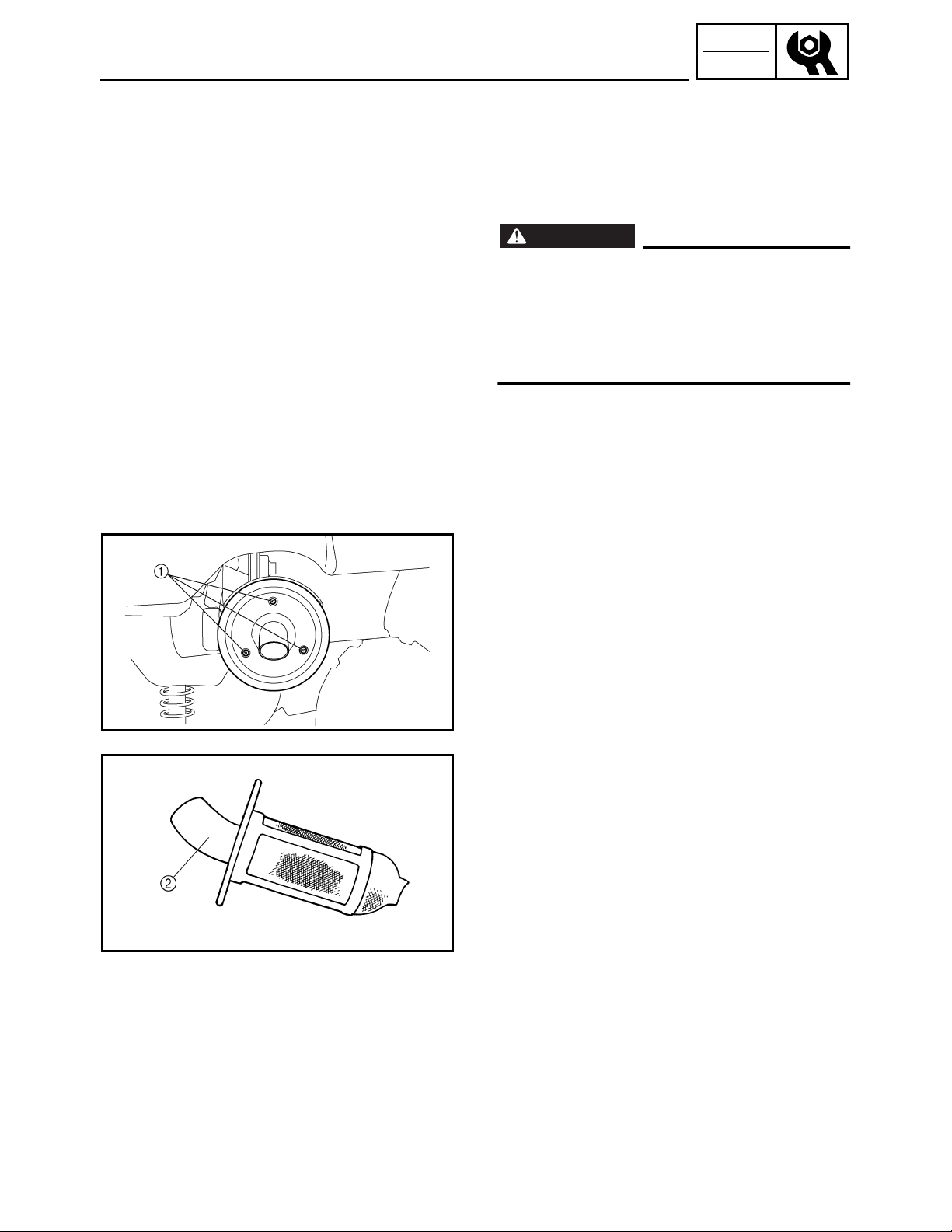
CLEANING THE SPARK ARRESTER
CLEANING THE SPARK ARRESTER
1.Clean:
●
Spark arrester
*****************************************************
Cleaning steps:
WARNING
Select a well-ventilated area free of
●
combustible materials.
Always let the exhaust system cool
●
before performing this operation.
Do not start the engine when removing
●
the tailpipe from the muffler.
CHK
ADJ
●
Remove the bolts 1.
●
Remove the tailpipe 2 by pulling it out of the
muffler.
●
Tap the tailpipe lightly with a soft-face
hammer or suitable tool, then use a wire
brush to remove any carbon deposits from
the spark arrester portion of the tailpipe and
the inner contact surfaces of the muffler.
●
Insert the tailpipe 2 into the muffler and
align the bolt holes.
●
Insert the bolts 1 and tighten it.
*****************************************************
3 - 35
Page 97
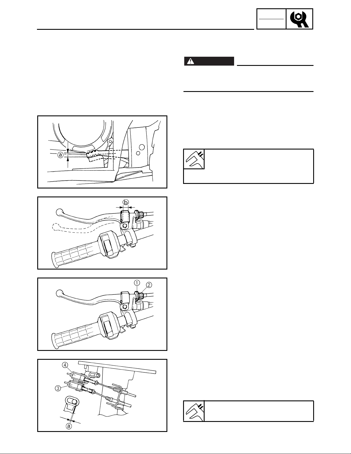
ADJUSTING THE REAR BRAKE
CHASSIS
ADJUSTING THE REAR BRAKE
WARNING
Always adjust both the brake pedal and the
rear brake lever whenever adjusting the
rear brake.
1.Check:
●
Rear brake pedal free play a
●
Rear brake lever free play b
Out of specification → Adjust.
Rear brake pedal free play:
20 ~ 30 mm (0.80 ~ 1.18 in)
Rear brake lever free play:
3 ~ 5 mm (0.12 ~ 0.20 in)
CHK
ADJ
3 - 36
2.Adjust:
●
Rear brake lever free play
●
Rear brake pedal free play
*****************************************************
Adjustment steps:
●
Loosen the locknut (handlebar) 1 and fully
screw in the brake lever cable adjuster
(handlebar) 2.
●
Fully loosen the brake lever cable adjusting
nut (drum) 3.
●
Turn the rear brake pedal cable adjusting
nut 4 until the brake pedal free play is within
the specified limits.
Rear brake pedal free play:
20 ~ 30 mm (0.8 ~ 1.2 in)
Page 98
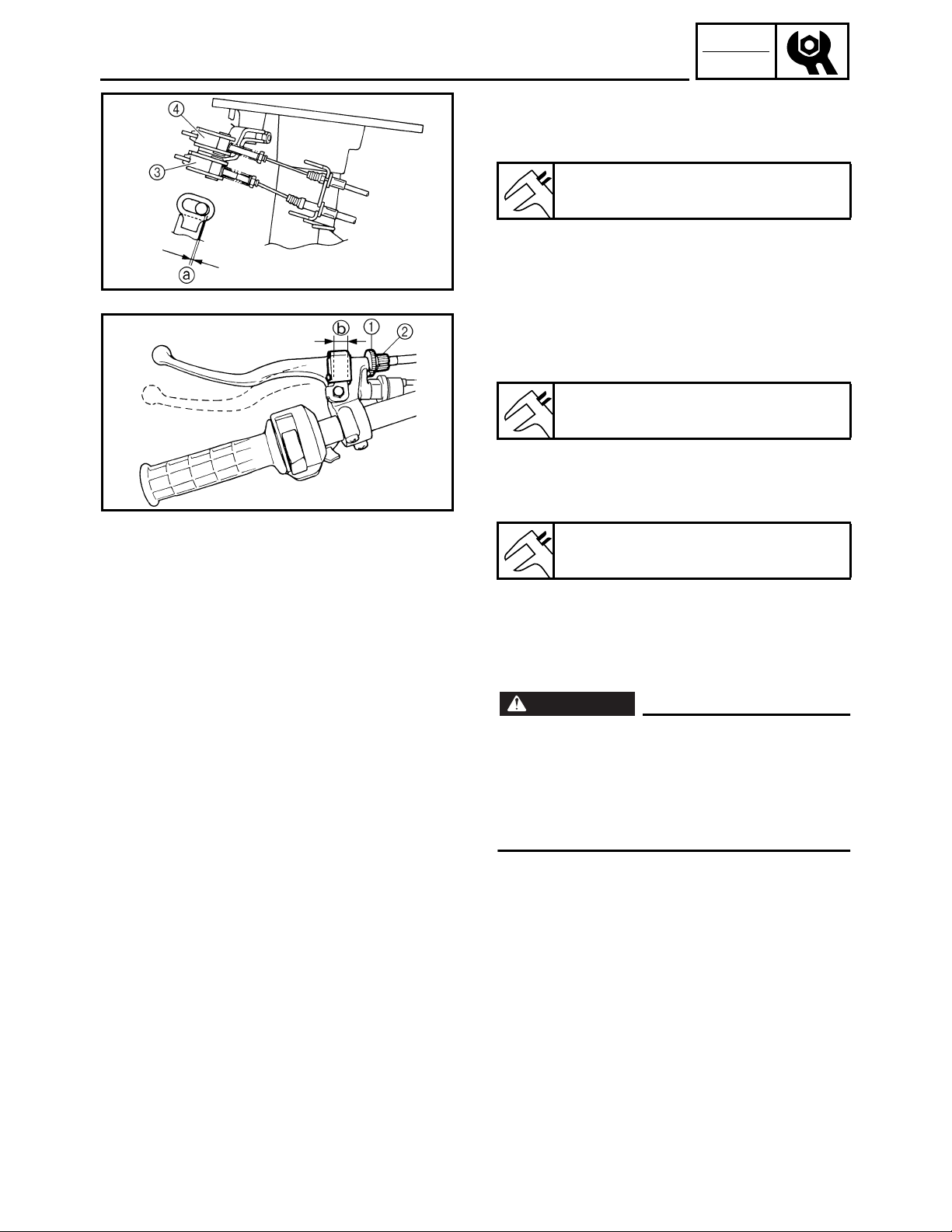
ADJUSTING THE REAR BRAKE
●
Turn the brake lever cable adjusting nut
(drum) 3 clockwise until the gap a is within
the specified limits.
Gap a:
0 ~ 1 mm (0.00 ~ 0.04 in)
●
Checking the rear brake pedal free play to see
whether or not it is within the specified limits. If
not, perform the above steps again.
Rear brake pedal free play:
20 ~ 30 mm (0.8 ~ 1.2 in)
●
Turn the brake lever cable adjusting nut
(handlebar) 2 until the rear brake lever free
play b is within the specified limits.
CHK
ADJ
Rear brake lever free play:
3 ~ 5 mm (0.12 ~ 0.20 in)
●
Tighten the locknut (handlebar) 1.
●
Adjust the select lever control cable.
Refer to “ADJUSTING THE SELECT LEVER
CONTROL CABLE AND SHIFT ROD”.
WARNING
After this adjustment is performed, lift the
front and rear wheels off the ground by
placing a block under the engine, and spin
the rear wheels to ensure there is no brake
drag. If any brake drag is noticed perform
the above steps again.
*****************************************************
3 - 37
Page 99
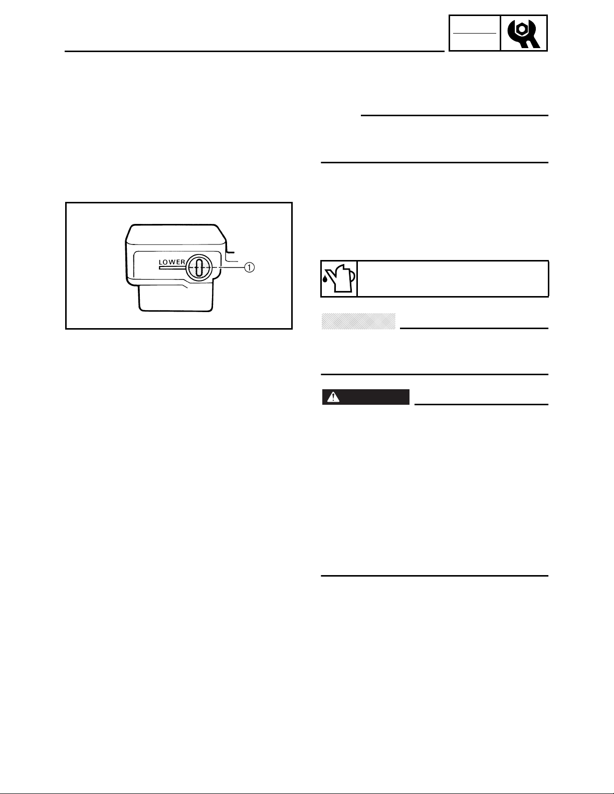
CHECKING THE FRONT BRAKE FLUID LEVEL
CHECKING THE FRONT BRAKE FLUID
LEVEL
1.Place the machine on a level surface.
OTE:
When checking the front brake fluid level,
make sure that the top of the master cylinder
top is horizontal.
2.Check:
●
Brake fluid level
Fluid level is under “LOWER” level line 1 →
Fill up.
Recommended brake fluid:
DOT 4
CHK
ADJ
CAUTION:
Brake fluid may erode painted surfaces or
plastic parts. Always clean up spilled fluid
immediately.
WARNING
Use only the designed quality brake fluid:
●
otherwise, the rubber seals may
deteriorate, causing leakage and poor
brake performance.
Refill with the same type of brake fluid;
●
mixing fluids may result in a harmful
chemical reaction and lead to poor
performance.
Be careful that water does not enter the
●
master cylinder when refilling. Water will
significantly lower the boiling point of the
fluid and may result in a vapor lock.
3 - 38
Page 100

CHECKING THE FRONT BRAKE PADS/
CHECKING THE REAR BRAKE SHOES
CHECKING THE FRONT BRAKE PADS
1.Remove:
●
Front wheel
2.Check:
●
Brake pads
Wear indicator groove 1 almost touch the
brake disc → Replace the brake pads as a
set.
Refer to “FRONT BRAKE” in CHAPTER 8.
Brake pad wear limit a:
1 mm (0.04 in)
3.Operate the brake lever.
4.Install:
●
Front wheel
CHK
ADJ
CHECKING THE REAR BRAKE SHOES
1.Operate the brake lever or brake pedal.
2.Check:
●
Wear indicator 1
Reaches the wear limit line 2 → Replace
the brake shoes as a set.
Refer to “REAR BRAKE” in CHAPTER 8.
3 - 39
 Loading...