

Yamaha Libero G5 Owner's Manual
PRINTED IN INDIA
2Y14(OM-01)284-11-06-E
ger Engine Life
er Maintenance Cost
er Exhaust Smoke
uces Wear and Tear
G
STROKE MOTOR OIL
20W40
4
OWNER'S MANUAL
1B5-F8199-E0
1B56
YAMAHA
YAMAHA
1B5-F8199-E0
TAKE NECESSARY PRECAUTIONS DURING RUNNING-IN PERIOD.
LIBERO
OWNER'S MANUAL
YAMAHA MOTOR INDIA PVT. LIMITED
All rights reserved. Any reprinting or
unauthorised use without the written
permission of
YAMAHA MOTOR LIMITED
is expressly prohibited.
INDIA PVT.
WARNING
PLEASE READ THIS MANUAL CAREFULLYAND COMPLETELYBEFORE OPERATING THIS MOTORCYCLE.

INTRODUCTION
Congratulations on your purchase of the . This motorcycle has been produced using the latest
technology in our modern plant, to provide you a happy, enjoyable and safe riding for many thousand
kilometers and years. It represents the high degree of craftsmanship and reliability that have made
a leader inthese fields.
This Owner's Manual will give you an understanding of the operation, inspection and basic maintenance of
this Motorcycle. To ensure a long trouble free performance, please take due care and ensure proper
maintenance of your Motorcycleas recommended in this Owner's Manual. Always demandonly
Genuine Spare Parts and Yamalube oil. If you have any queries regarding the operation or maintenance of
your Motorcycle, pleaseconsult your DEALER who willbe too happy to help you.
This Owner's Manual also includes the GREEN BOOK containing Guidelines, DO's and DON'Ts to be
followed by the Owner/ User of the Motorcycle for keeping Environment Clean and Green. You are
requested to pleaseread the GREEN BOOK carefully.
We Provide
At YourCaring Service,
A-3, Industrial Area, Noida Dadri Road
Surajpur-201 306 (India)
LIBERO
YAMAHA
YAMAHA
YAMAHA
YAMAHA MOTOR INDIA PVT.LTD.
Particularly important information is distinguished in this manual by the following notations:
IMPORTANT MANUAL INFORMATION
•
•
This manual should be considered a permanent part of this Motorcycle and should
remain with iteven if the Motorcycle is subsequentlysold.
YAMAHA continually seeks advancements in product design and quality. Therefore,
while this manual contains the most current product information available at the time of
printing, there may be minor discrepancies betweenyour Motorcycle and this manual.If
there is anyquestion concerning this manual, please consultyour YAMAHA dealer.
The SafetyAlert Symbol means ATTENTION! BECOME ALERT ! YOUR SAFETY
IS INVOLVED !
NOTE :
CAUTION :
WARNING
Failure to follow WARNING instructions to the
Motorcycle operator, a bystander or aperson inspecting or repairing the Motorcycle.
could result in severe injury
A CAUTION indicates special precautions that mustbe taken toavoid damage tothe
Motorcycle.
ANOTE provides key information tomake procedures easier or clearer.
NOTE :
ROAD SAFETY TIPS ....................................... 1-1
DESCRIPTION ................................................ 2-1
Left view ........................................................ 2-1
Right view ...................................................... 2-2
Controls/Instruments ................................... 2-3
INSTRUMENT AND CONTROL
FUNCTIONS .................................................... 3- 1
Main switch cum steering lock ..................... 3-1
Speedometer ................................................ 3-2
Fuel gauge .................................................... 3-2
Indicator lights .............................................. 3-2
Handlebar switches ..................................... 3- 3
Clutch lever ................................................... 3-3
Shift pedal ..................................................... 3-4
Front brake lever ........................................... 3-4
Rear brake pedal .......................................... 3-4
Fuel tank cap ................................................ 3-5
Fuel ............................................................... 3-5
Fuel cock ....................................................... 3-6
Starter Lever .................................................. 3-7
Kick starter .................................................... 3-7
Seat ............................................................... 3-8
Storage compartment .................................. 3-9
Rear shock absorber adjustment ............... 3-9
Handle Seat, Lifting Handle, stay Lock ....... 3-10
PRE-OPERATION CHECKS ........................... 4-1
Pre-operation check list ............................... 4-1
OPERATION AND IMPORTANT RIDING
POINTS ............................................................ 5-1
Starting and warming up a
cold engine ................................................... 5- 1
Starting a warm engine ................................ 5-2
Shifting .......................................................... 5-2
Tips for reducing fuel consumption ............. 5-3
Running-in .................................................... 5-3
Parking .......................................................... 5-4
PERIODIC MAINTENANCE AND MINOR
REPAIR ............................................................ 6- 1
Tool kit ........................................................... 6-1
Preventive maintenance schedule .............. 6- 3
Panel removal and installation .................... 6-5
Spark plug inspection .................................. 6-7
Engine OIl ..................................................... 6-8
1
4
2
3
6
5
TABLE OF CONTENTS
Libero5TS8.pmd 11/3/2006, 8:50 PM1

TABLE OF CONTENTS
Air filter ........................................................... 6-10
Carburetor adjustment ................................. 6-11
Idle speed adjustment ................................. 6-12
Throttle cable free play adjustment ............. 6-12
Valve clearance adjustment ......................... 6-13
Tyres .............................................................. 6-13
Wheels .......................................................... 6-15
Clutch lever free play adjustment ................ 6-16
Front brake adjustment ................................ 6-16
Rear brake adjustment ................................ 6-17
Brake light switch adjustment ..................... 6-17
Checking the brake shoes ........................... 6-18
Drive chain slack check ................................ 6-18
Drive chain slack adjustment ...................... 6-19
Drive chain lubrication .................................. 6-21
Cable inspection and lubrication ................. 6-21
Throttle cable and grip lubrication ............... 6-21
Brake and shift pedal lubrication ................. 6-22
Brake and clutch lever lubrication ................ 6-22
Center and sidestand lubrication ................ 6-22
Front fork inspection ..................................... 6-23
Steering inspection ...................................... 6-23
Wheel bearings ............................................ 6-24
Battery ........................................................... 6-24
Fuse replacement ........................................ 6-26
Headlight bulb replacement ........................ 6-27
Turn signal and taillight bulb
replacement .................................................. 6-28
Front wheel removal ..................................... 6-28
Front wheel installation ................................ 6-30
Rear wheel removal ..................................... 6-30
Rear wheel installation ................................ 6-32
Troubleshooting ........................................... 6-32
Troubleshooting chart .................................. 6-33
CLEANING & STORAGE
A. Cleaning .................................................... 7-1
B. Storage ...................................................... 7-2
SPECIFICATIONS ........................................... 8-1
CUSTOMER INFORMATION ........................... 9-1
Key identification number ............................. 9-1
Frame serial number ................................... 9-1
Engine serial number .................................. 9-1
DETATCHMENTS
Pre-Delivery Inspection ................................ 10-1
Installation .................................................... 10-5
GREEN BOOK
7
8
9
10
Libero5TS8.pmd 11/3/2006, 8:50 PM2

ROAD SAFETY TIPS
SAFE RIDING
1. Before riding, you should learn to ride your motorcycle properly and all the control functions should be known
to you.
2. Remember that there are no legal “rights” when it comes to survival as far as Motorcyclists are
concerned. The fact that you may be well within your rights is no guarantee that you will avoid a collision with
a bigger vehicle whose driver fails to see you. Always ride defensively and take nothing on road for granted.
3. Develop the ability to react swiftly to any unexpected road hazards or emergencies giving yourself time to
spare for appropriate response.
4. Develop the ability to get the most out of your Motorcycle, But at the same time get to know its capabili-
ties and limitations.
5. Ride thoughtfully, planning your route well in advance.
6. Give proper Signals and use Horn and Headlights judiciously.
7. Don’t ride in another motorist’s blind spot.
8. Always make pre-ride safety checks before you start the Engine.
SAFE BRAKING
Use the basic methods of braking effectively.
1. Engine Brake : When the Throttle is released, compression backs up and acts as the Engine Brake.
If the riding condition allows, reduce speed by shifting the Gear down.
2. Front and Rear Brakes : It is important to apply equal force to the Front and Rear Brakes simultaneously.
• Use Front and Rear Brakes simultaneously.
• Be sure not to disengage the clutch while braking.
• While riding downhill always use Engine as a Brake and never ride in Neutral Gear.
• While riding down hill do not switch off ignition while Engine is in gear.
CAUTION :
1-1
Libero5TS8.pmd 11/3/2006, 8:50 PM3
DESCRIPTION
2-1
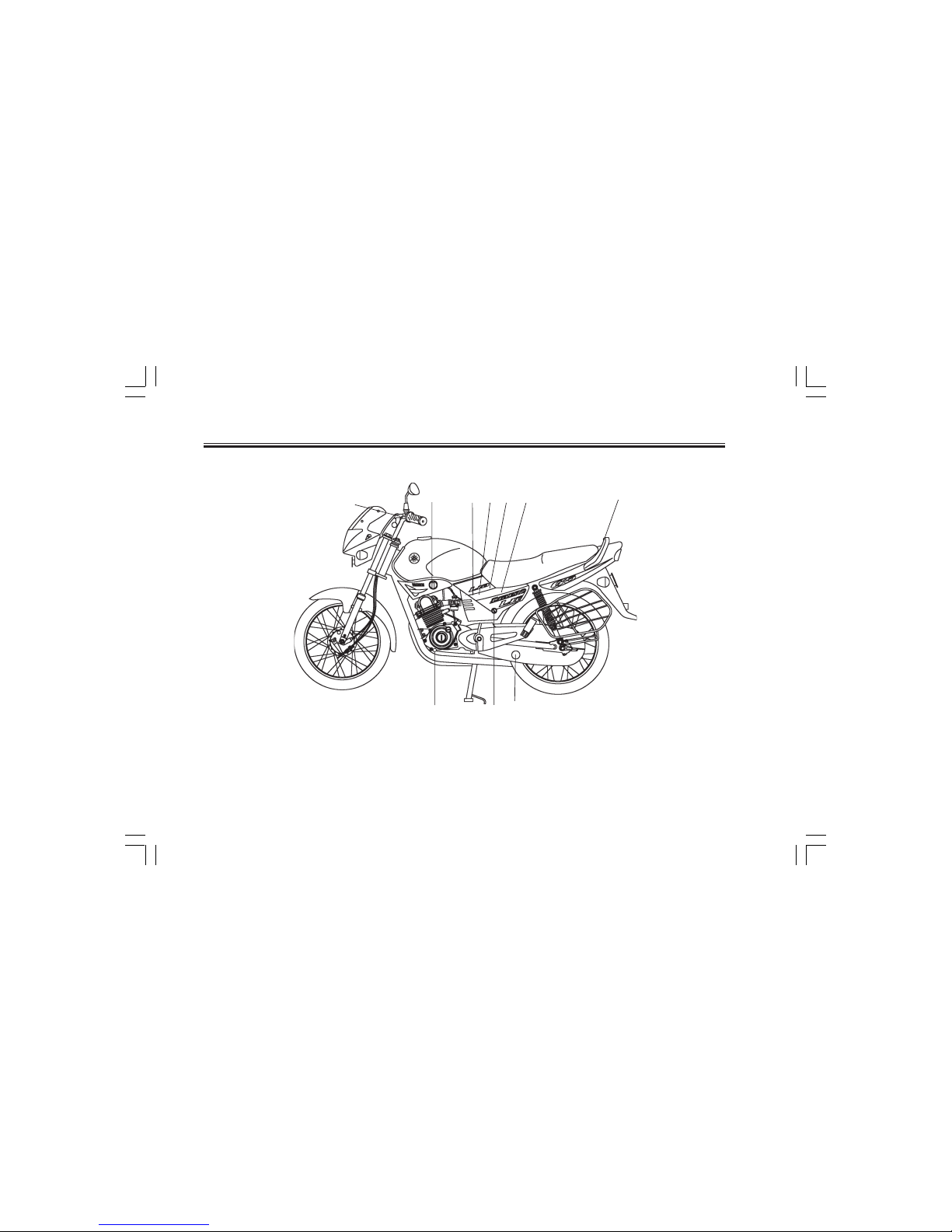
Left view
6. Toolkit (page 6-1)
7. Handle Seat (page 3-10)
8. Drive chain free play check window (page 6-19)
9. Side panel (L.H.) lock (page 6-5)
10. Shift pedal (page 3-4)
1. Fuel cock (page 3-6)
2. Starter Lever (page 3-7)
3. Fuse (page 6-26)
4. Battery (page 6-24)
5. Storage Compartment (page 3-9)
STANDARD VEHICLE
134
2
8
9
10
7
56
Libero5TS8.pmd 11/3/2006, 8:50 PM4
DESCRIPTION
2-2
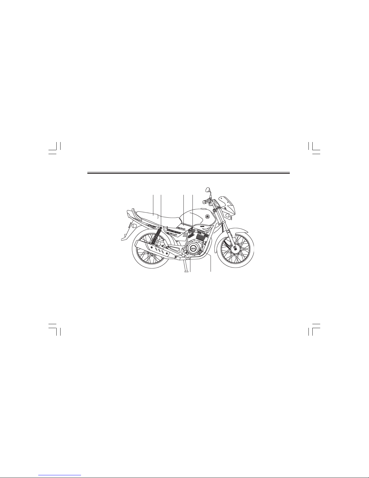
Right view
11. Rear shock absorber (page 3-9)
12. Air filter (page 6-10)
13. Kick starter (page 3-7)
14. Seat (page 3-8)
15. Engine oil filler cap (page 6-8)
16. Rear brake pedal (page 3-4,6-17)
STANDARD VEHICLE
15
11 12 1314
16
Libero5TS8.pmd 11/3/2006, 8:50 PM5
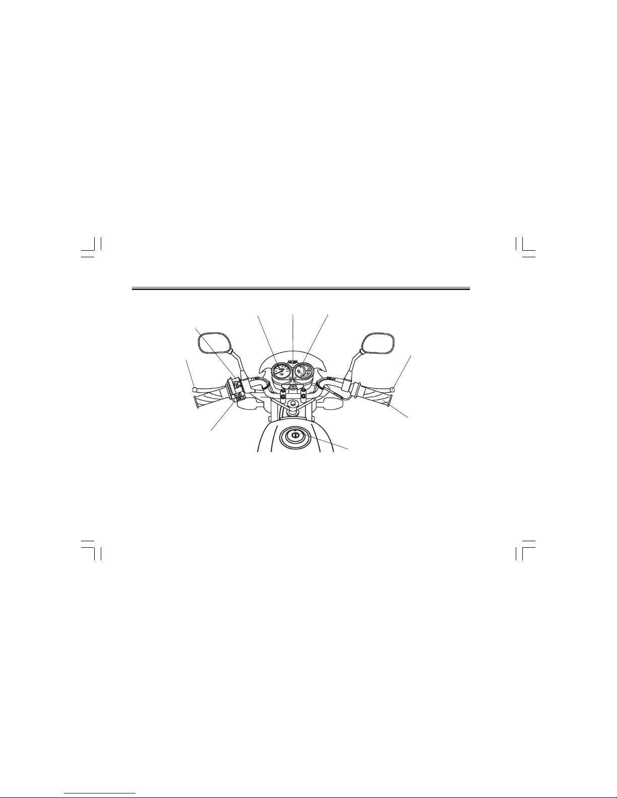
17. Clutch Lever (page 3-3, 6-16)
18. Left Hand Switch (page 3-3)
19. Speedometer (page 3-2)
20. Main switch Cum Steering Lock (Page 3-1)
21. Fuel Gauge (page 3-2)
22. Front Brake Lever (page 3-4, 6-16)
23. Throttle Grip (page6-12)
24. Fuel Tank Cap (page 3-5)
25. Turn Indicator Switch (page 3-2)
Controls / Instruments
DESCRIPTION
STANDARD VEHICLE
2-3
24
17
18
19
20
21
23
25
22
Libero5TS8.pmd 11/3/2006, 8:50 PM6
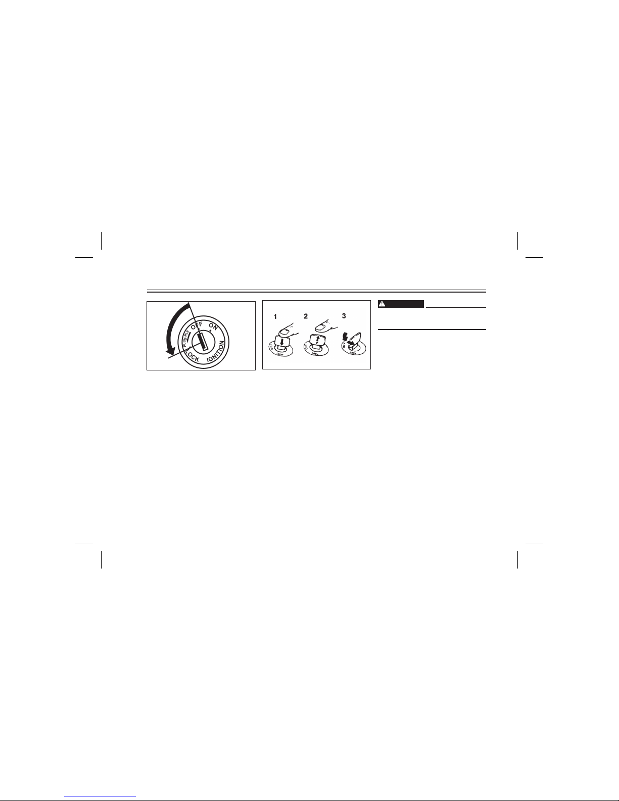
Main switch cum steering
lock
The main switch controls the ignition
and lighting systems. Its operation is
described below.
ON:
Electrical circuits are switched on.
The engine can be started. The key
cannot be removedin this position.
OFF:
Engine will be shut off. All electrical
circuits are switched off. The key can
be removed inthis position.
1. Push
2. Release
3. Turn
LOCK:
The steering is locked in this position
and all electrical circuits are switched
off.
The key can be removed in this
position.
To lock the steering, turn the handlebars allthe way to theleft or right. With
the key at "OFF", push it into the main
switch and release it, turn it counterclockwise to "LOCK"and remove it. To
release the lock, turn the key to
"OFF".
INSTRUMENT AND CONTROL FUNCTIONS
WARNING
Never turn the key to "LOCK" when
the Motorcycle ismoving.
3-1
INSTRUMENT AND CONTROL FUNCTIONS
3-2
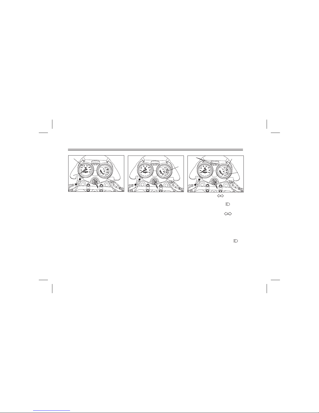
1. Turn indicator light “ ”
2. Neutral ”N”
3. High beam.Indicator light “ ”
1. Speedometer
2. Odometer
1. Fuel gauge
1
1
2
Speedometer
The speedometer shows riding
speed.
This speedometer is equipped with
an odometer.
Fuel gauge
The fuel gauge indicates the quantity
of the remainingpetrol in the fuel tank.
The gauge needle moves from “F”
(Full) to"E”(Empty) as the fuel level
decreases.
When the needle comes below “E”
please refill the fuel tank at the
earliest.
Indicator lights
1. Turn indicator light " "
2. Neutral indicatorlight "N"
3. High beamindicator light " "
The indicator flashes when the
turn switch is moved to the left or
right. .
This indicator comes on when the
transmission is inneutral.
This indicator comes on when the
headlight high beamis used.
1
2
3
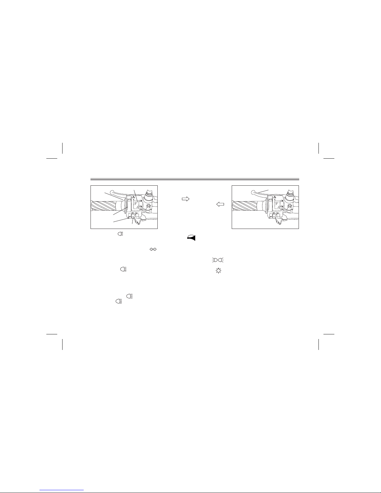
Turnsignal switch
Horn switch " "
Lights switch
To signal a right-hand turn, push the
switch to " ". To signal a lefthand turn, push the switch to " ".
Once the switch is released it will
return to the center position. To
cancel the signal, push the switch in
after it has returned to the center
position.
Press the switch to sound the horn.
Turning the light switch to " ",
turns on the meter light and tail-light.
Turning the light switch to “ ",
turns the headlight on also.
1. Clutch lever
Clutch lever
The clutch lever is located on the left
handlebar. Pull the clutch lever to
the handlebar to disengage the
clutch, and release the lever to
engage the clutch. The lever should
be pulled rapidly and released slowly
for smooth clutch operation.
INSTRUMENT AND CONTROL FUNCTIONS
3-3
1. PassSwitch " "
2. Dimmer Switch
3. Light switch
4. Turn signal cum cancellation switch“ “
5. Horn switch
Handlebar switches
Dimmer switch
Turn the switch to" " for the high
beam and to" " for the lowbeam.
Pass switch ""
Press the switch to operate the
Passing Light.
1
1
2
3
4
5
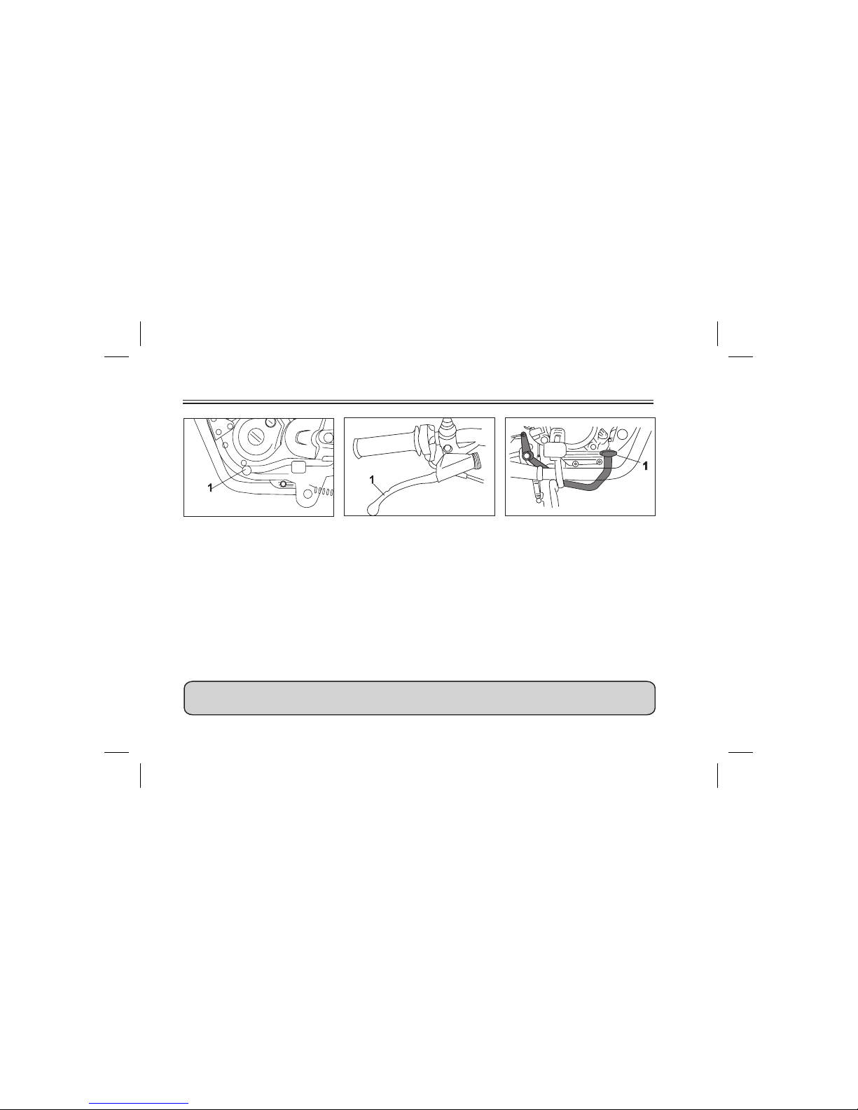
1. Shift pedal
Shift pedal
The shift pedal is located on the left
side of the engine and is used in
combination with the clutch when
shifting.
Use your toe or heel to shift up and
your toe toshift down.
1. Front brake lever
Front brake lever
The front brake lever is located on
the right handlebar. Pull it toward the
handlebar to apply the front brake.
1 Rear brake pedal
Rear brake pedal
The rear brake pedal is on the right
side ofthe Motorcycle. Pressdown on
the brake pedal to apply the rear
brake.
INSTRUMENT AND CONTROL FUNCTIONS
USE BOTH BRAKES SIMULTANEOUSLY
3-4
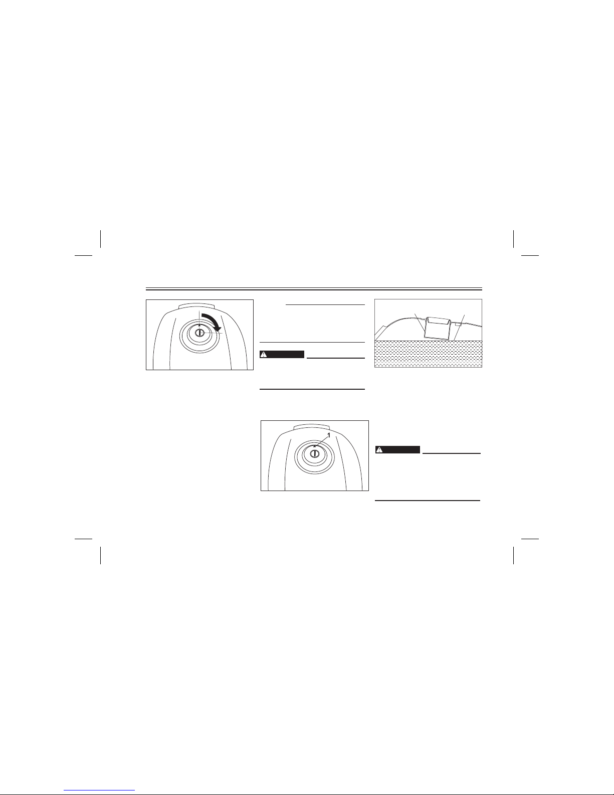
This tank cap cannot be closed
unless the key is in the lock. The key
cannot be removed if the cap is not
locked properly.
Be sure the cap is properly
installed and locked in place
before riding theMotorcycle.
WARNING
1. Filler tube
2. Fuel level
Fuel
Make surethere is sufficientfuel in the
tank. Fill the fuel tank to the bottom of
the filler tube as shown in the
illustration.
Do not overfill the fuel tank. Avoid
spilling fuel on the hot engine. Do
not fill the fuel tank above the
bottom of the filler tube to avoid
Spillage
1. Open
Fuel tank cap
TO OPEN:
Insert the key and turn it 1/4 turn
clockwise. The lock will be released
and the cap can be opened.
TO CLOSE:
Push the tank cap into position with
the key inserted. To remove the key,
turn it counterclockwise to the
original position.
Ensure the arrow on fuel tank is
towards the Front of the bike when
inserting Fuel Tank Cap in Fuel
Tank.
INSTRUMENT AND CONTROL FUNCTIONS
NOTE :
3-5
WARNING
WARNING
1
2
1
1. Arrow
1
¿
Always wipe off spilled fuel
immediately with a dry and clean
soft cloth. Fuel may deteriorate
painted surfaces orplastic parts.
Recommended Fuel :
Fuel tank capacity:
Regular gasoline (Petrol)
Total :
13.0 L
Reserve :
1.7 L
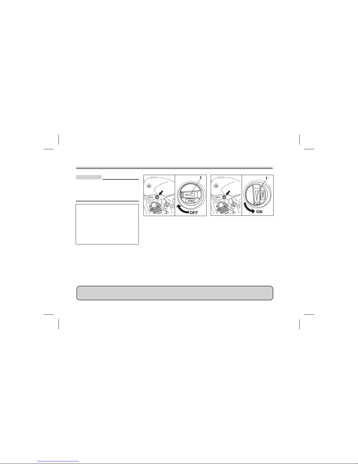
1. Arrow mark
Fuel cock
The fuel cock supplies fuel from the
tank to the carburetor while filtering it
also.
The fuel cock has three positions,
which should be set as shown in the
illustrations.
OFF: With the fuel cock in this
position, fuel will not flow.
Always set the fuel cock to this
position when the engine is not
running.
1. Arrow mark
ON: With the fuel cock in this
position, fuel flows to the
carburettor. Set the fuel cock to
this position when starting the
engine and whileriding.
INSTRUMENT AND CONTROL FUNCTIONS
3-6
CAUTION :
IT IS A GOOD PRACTICE TO RETURN THE FUEL COCK LEVER TO
"Off" POSITION WHEN ENGINE IS NOT RUNNING
OFF
1 1
ON
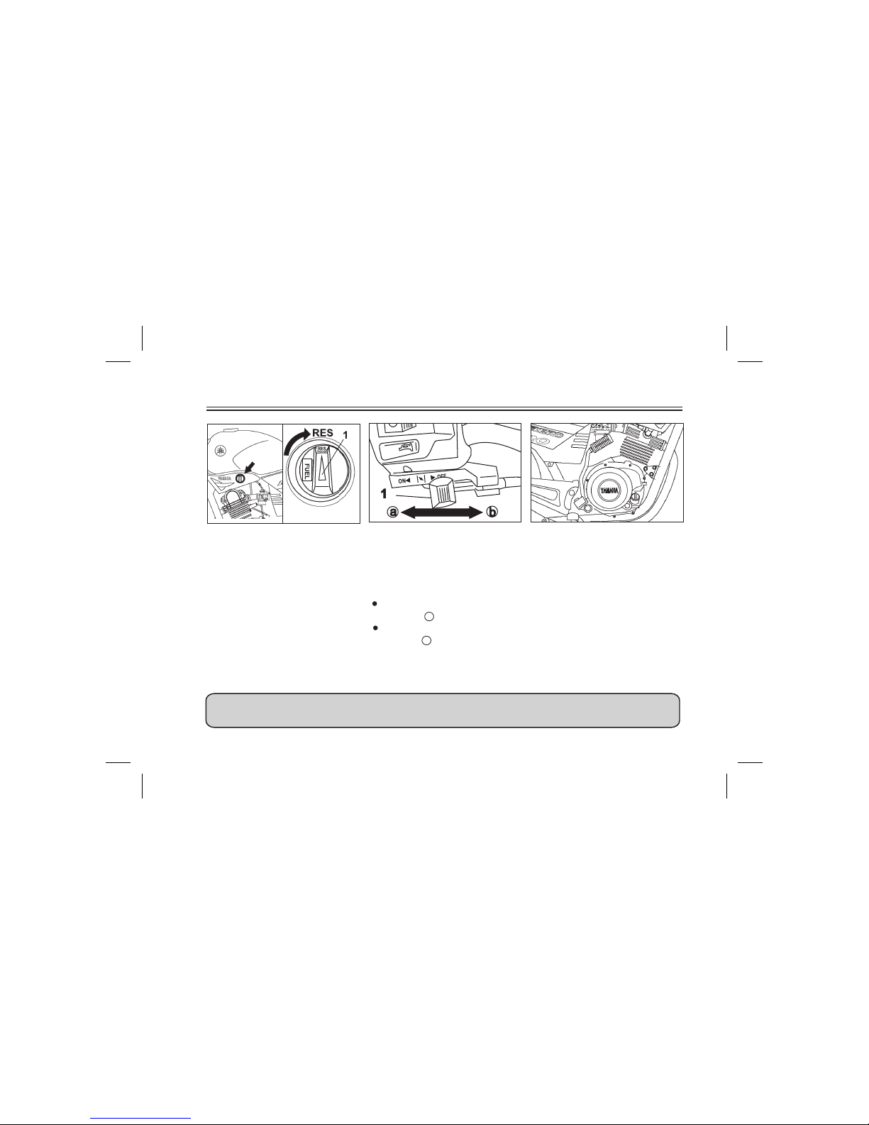
1. Arrow mark
RES: This indicates reserve. If you
run out of fuel while riding, set
the fuel cock to this position.
Fill the tank at the first
opportunity. Be sure to set the
fuel cock back to "ON" after
refueling
1. Kick starter
Kick-starter
Raise the right Pillion footrest, and
rotate the kick starter away from the
engine. Push the starter down
lightly with your foot Kick until the
gears engage, then kick smoothly and
forcefully to start the engine. This
model has a primary-coupled kick
starter so the engine can be started in
any gear if the clutch is disengaged.
However, shifting to neutral before
starting is recommended.
kick
INSTRUMENT AND CONTROL FUNCTIONS
3-7
NEVER MIX OIL IN PETROL
1. Starter lever
Starter lever
Starting a cold engine requires a
richer air-fuel mixture. A separate
starter circuit supplies this mixture.
Move the Starter Lever in
Direction a to Turn onthe Starter
Move the Starter Lever in
Direction b to TurnOff the Starter
RES
1
3-8
INSTRUMENT AND CONTROL FUNCTIONS
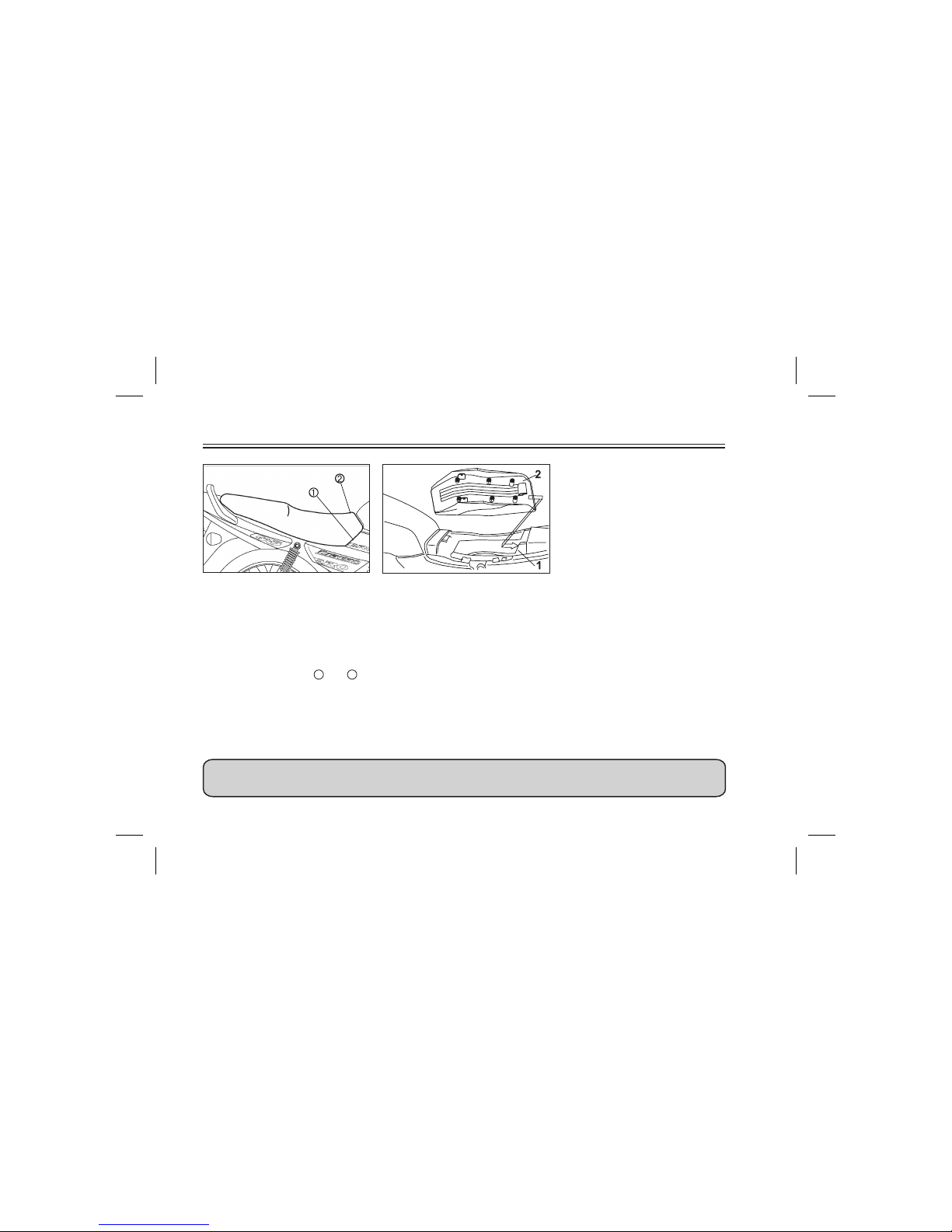
1. Open
2. Open
Opening of Seat
To remove
Open side panels as per instructions
on page 6-5.
Remove the two bolts 1 and 2 as
shown in figure. Lift the front of the
seat and slide forward to remove.
1. Seat Holder
2. Projection
To install
Insert the projection on the rear of
seat in to seat holder. Then push
down on front of the seat and tighten
the bolts on the left and right hand
side of the seat.
ALWAYS USE A HELMET WHILE RIDING FOR YOUR SAFETY
1
1. Storage compartment
Storage compartment
The storage compartment is located
inside the L.H.Side Cover
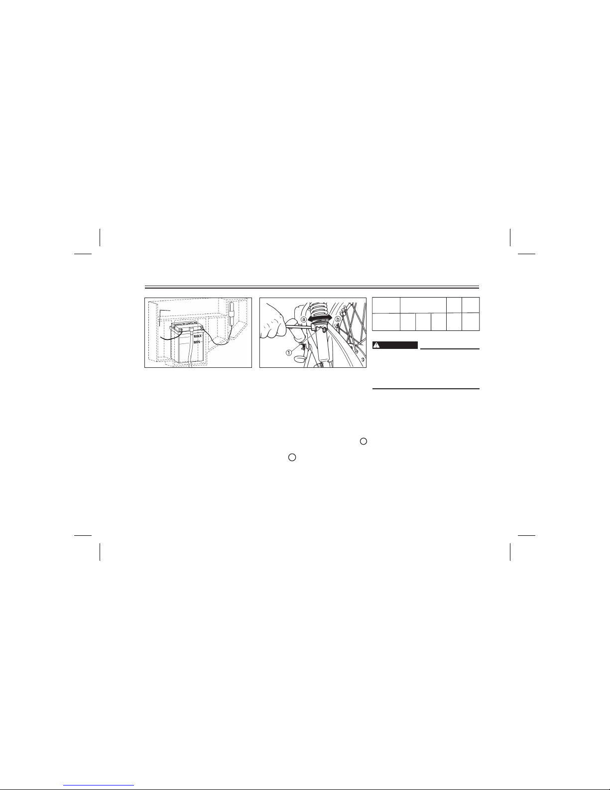
1. Spring preload adjusting ring
2. Positionindicator
Rear shock absorber
adjustment
Each shock absorber is equipped
with a spring preload adjusting ring.
Adjust spring preload as follows.
Turn the adjusting ring in direction a
to increase spring preload and in
direction b to decrease spring
preload. Make sure that the
appropriate notch in the adjusting
ring is aligned with the position
indicator on the rear shock absorber.
Always adjust each shock
absorber to the same setting.
Uneven adjustmentcan cause poor
handling and lossof stability.
INSTRUMENT AND CONTROL FUNCTIONS
3-9
WARNING
Adjusting
Position
Soft
12345
Hard
Standard
1
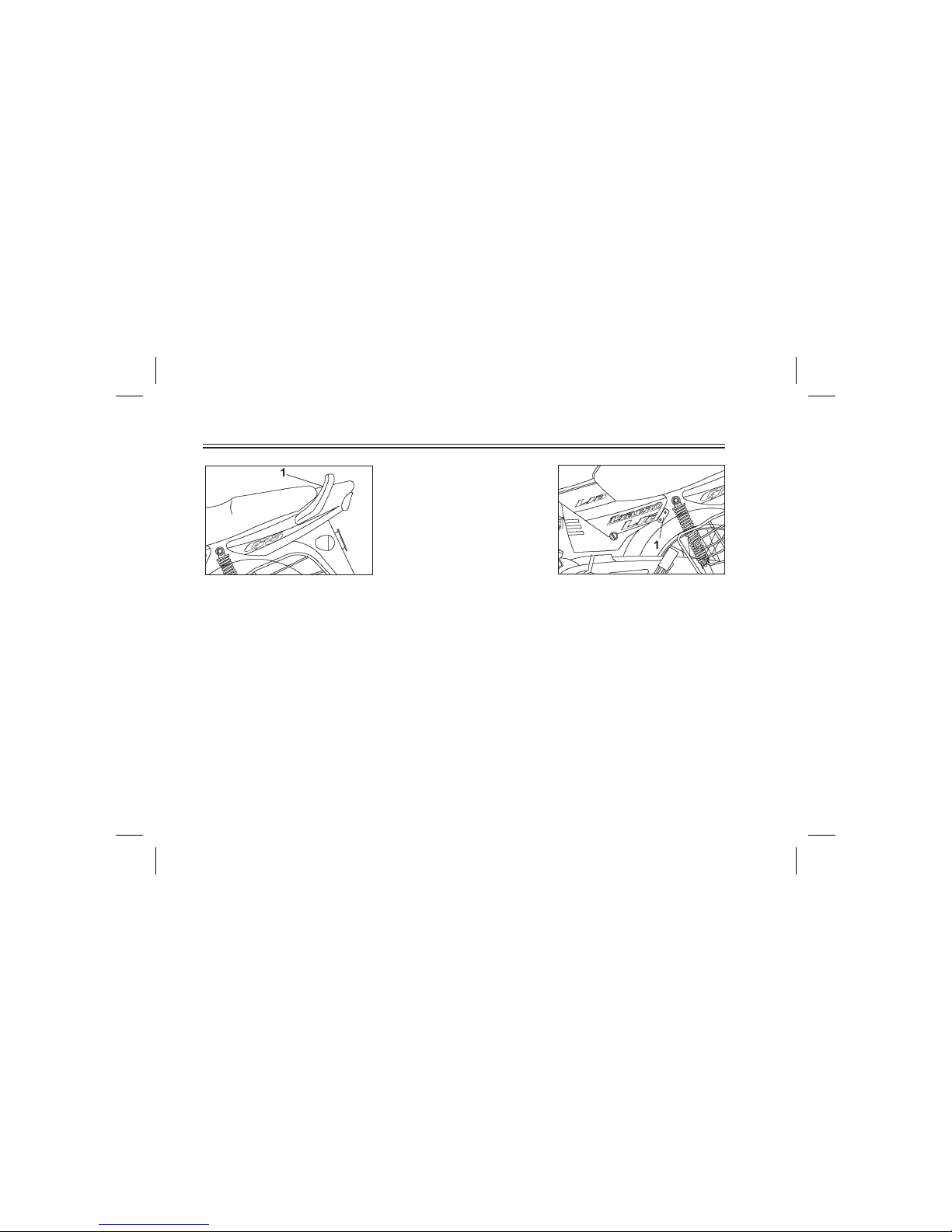
INSTRUMENT AND CONTROL FUNCTIONS
3-10
1. HandleSeat
1
1. Stay Lock
Stay Lock
For mounting Helmet Lock
PRE-OPERATION CHECKS
4-1
Owners are personally responsible for their vehicle's condition. Your Motorcycle's vital functions can start to
deteriorate quickly and unexpectedly- even if it remains unused (for instance, if it is exposed to the elements). Any
damage. fluid leak or loss of tyre pressure could have serious consequence Therefore' it is very important that, in
addition to a thorough visual inspection, you check the following points before each ride.
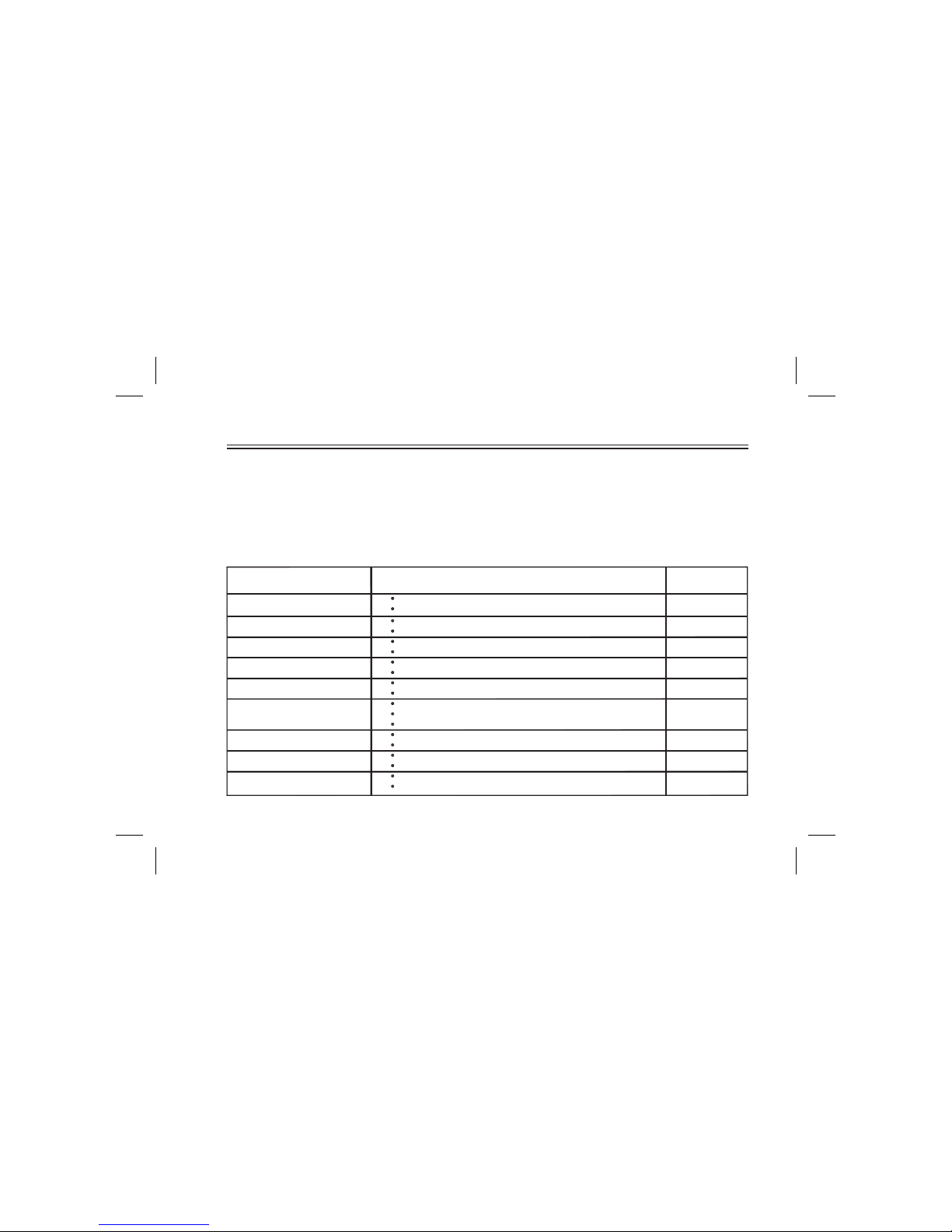
PRE - OPERATION CHECK LIST
Brake and shift pedal shafts
Engine oil
Control and meter cable
Wheels and tyres
Drive chain
Clutch
Throttle grip and housing
Rear brake
Front brake
Lubricate if necessary.
Check tyre pressure, wear, damage and spoke tightness.
Lubricate if necessary.
Check for smooth operation.
Lubricate if necessary.
Check for smooth operation.
Tighten spokes if necessary.
Adjust if necessary.
6-21
6-22
6-13 ~ 6-15
6-18 ~ 6-21
Check oil level.
Fill with oil if necessary.
Check chain slack and condition.
Check operation, condition and free play.
Adjust if necessary.
Lubricate if necessary.
Check for smooth operation.
Adjust if necessary.
Check operation, condition and free play.
Adjust if necessary.
Check operation, condition and free play.
ITEM CHECKS
6-8 ~ 6-9
6-12, 6-21
3-3, 6-16
3-4, 6-17
3-4, 6-16
PAGE
If anyitem in thePre-Operation Check isnot working properly, haveit inspected andrepaired before operating
the Motorcycle.
WARNING
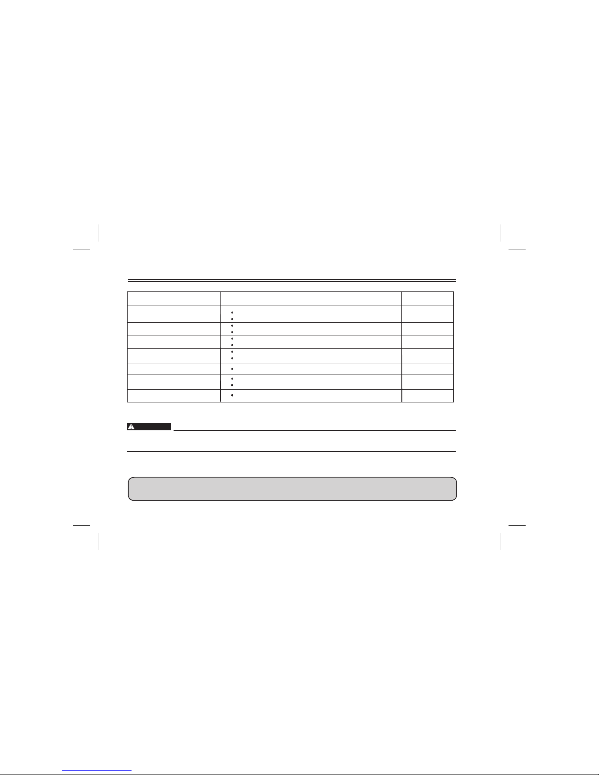
Fuel gauge
Check for proper operation/Function
3.2
PRE-OPERATION CHECKS
4-2
Fuel Tank
Brake and clutch lever pivots
Battery
Lights, signals and switches
Chassis fasteners
Center and sidestand pivot
Make sure that all nuts, bolts, and screws are properly tightened.
Tighten if necessary.
Check fuel level.
Fill with fuel if necessary.
Fill with distilled water if necessary.
Check fluid level.
Check for proper operation.
6-24~ 6-26
3-3, 6-27 ~ 6-28
3-5 ~ 3-7
Lubricate if necessary.
Check for smooth operation.
Lubricate if necessary.
Check for smooth operation.
ITEM CHECKS
6-22
PAGE
6-22
-
IF WAITING AT TRAFFIC SIGNAL IS FOR LONG, SWITCH OFF THE ENGINE
TO PROTECT THE ENVIRONMENT AND TO LOWER FUEL CONSUMPTION
OPERATION AND IMPORTANT RIDING POINTS
1. Before riding this Motorcycle,
become thoroughly familiar
with all operating controls and
their functions. Consult a
YAMAHA dealer regarding any
control or function that you do
not thoroughly understand.
2. Never start your engine or let it
run for any length of time in a
closed area. The exhaust fumes
are poisonous and can cause
loss of consciousness.
Always operate your
Motorcycle in an area with
adequate ventilation.
3. Before starting out, always be
sure the side stand is up.
Failure to retract the side stand
completely can result in a
serious accident when you try
to turn acorner.
Starting and warming up a
cold engine
1. Turn the fuel cockto "ON"
2. Turn the main switchto "ON."
3. Shift the transmission into
neutral.
When the transmission is in neutral,
the neutralindicator light should beon.
If the light does not come on, ask a
YAMAHA dealer toinspect it.
4 Fully open the Starter Lever and
completely close thethrottle grip.
5. Kick the kick starter to start the
engine.
6. After starting the Engine, turn back
the Starter Lever to the Warmingup Position (AboutHalf way)
7. After Warming-up the Engine,
turn off the Starter Lever
completely.
For better engine performance
always warm up the engine. before
take off. Never open throttle fully
when engine is cold, otherwise
engine tends tostop.
The engine is warm when it
responds normally to the throttle
with the Starter Lever in “OFF”
direction.
5-1
WARNING
NOTE :
NOTE :
NOTE :
OPERATION AND IMPORTANT RIDING POINTS
Starting a warm engine.
The Starter Lever maynot be required
when the engineis warm.
See the "Running-in" section prior
to operating the Motorcycle for the
first time.
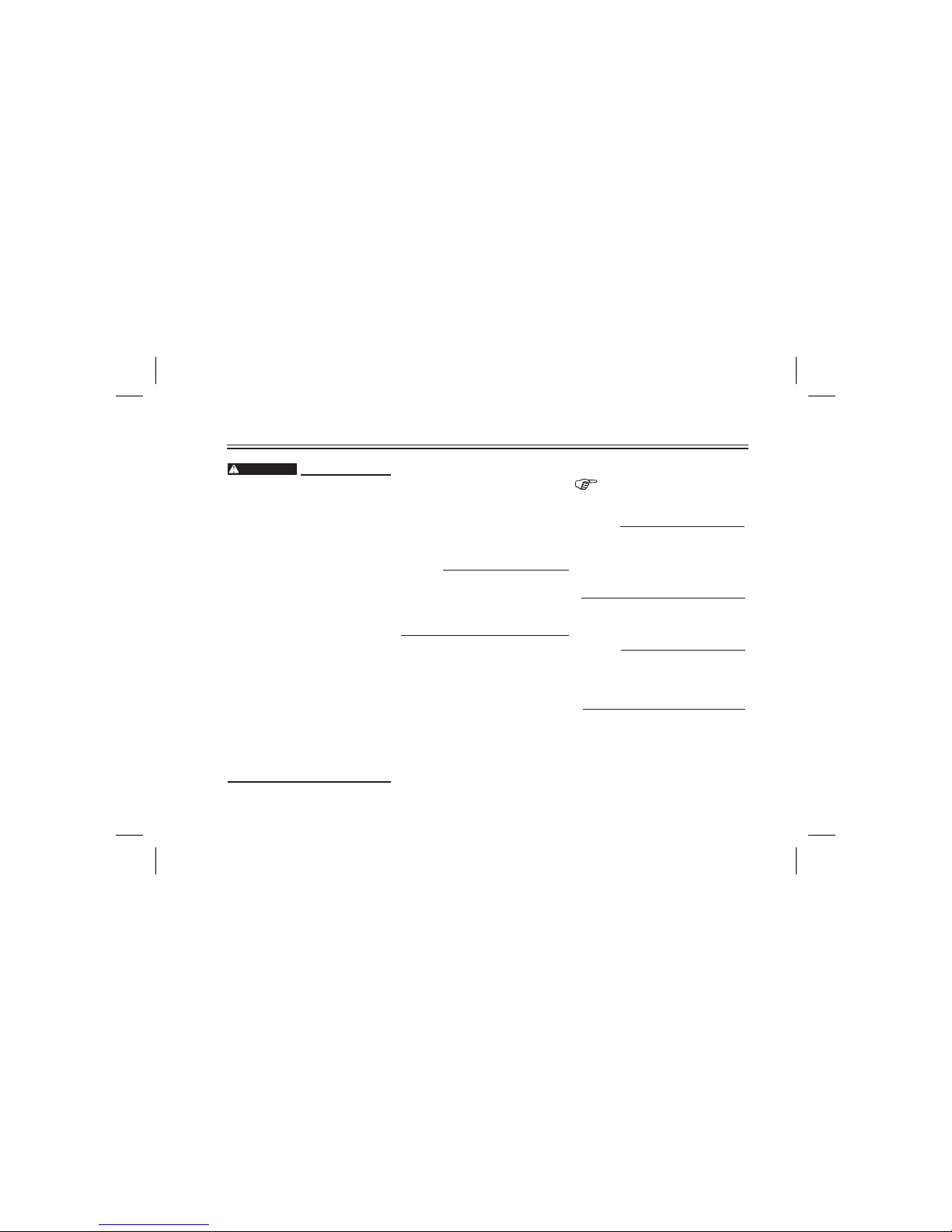
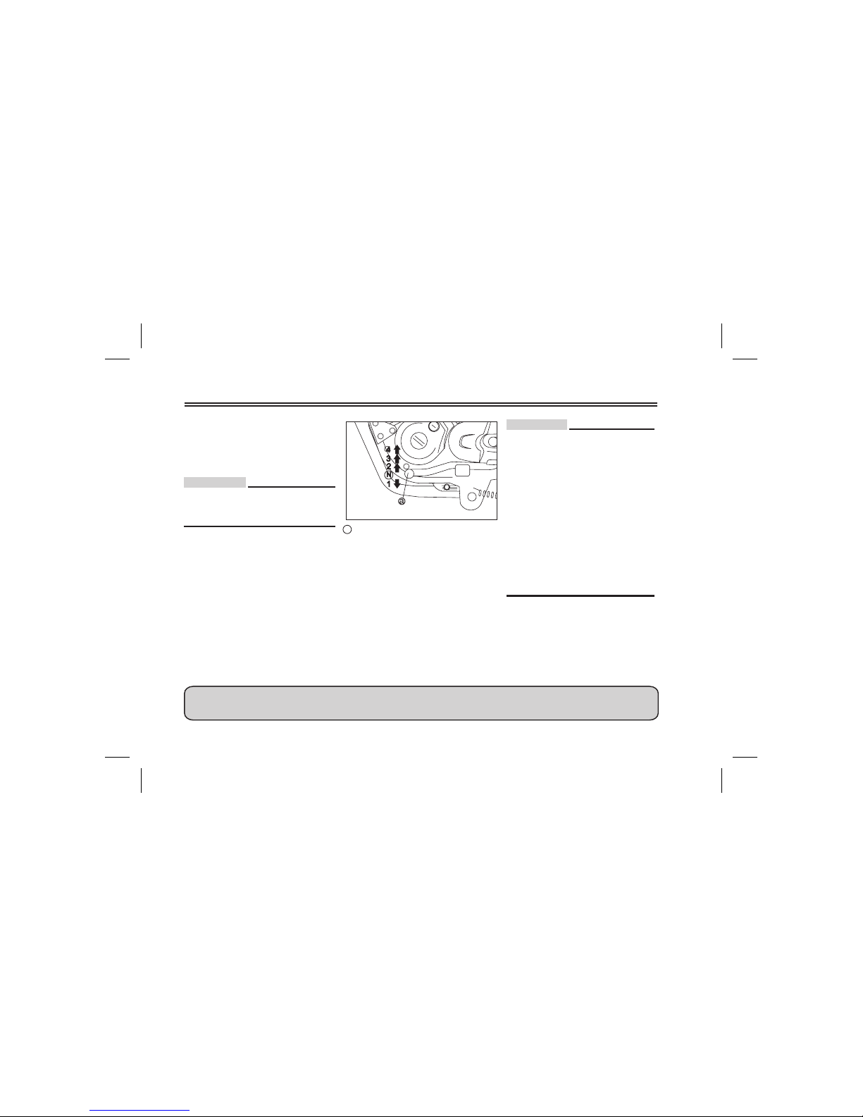
a Shift pedal
N. Neutral, 1,2,3,4 Gear Shift Position
Shifting
The transmission lets you control the
amount of power you have available
at a given speed for starting,
accelerating, climbing hills, etc. The
use of the shift pedal is shown in the
illustration.
To shift into neutral, depress the shift
pedal repeatedly until it reach- es
the end of its travel, then raise the
pedal slightly.
.
• Do not ride downhill with
Ignition Switch in “OFF”
Position & inNeutral Gear.
• Always ride motor cycle with
Ignition Switch in “ON”
Position & inNeutral Gear.
• Always use the clutch when
changing gears. The engine,
transmission, and driveline are
not designed to withstand the
shock of forced shifting and
can be damaged by shifting
without using theclutch.
5-2
CAUTION :
CAUTION :
NEVER RIDE MOTORCYCLE WITH CLUTCH PARTIALLY ENGAGED.
 Loading...