

YAMAHA KMA-1080, KMA-980 User Manual

KMA-1080/KMA-980
Digital Karaoke Mixing Amplifier
L
OWNER’S MANUAL
MANUAL DE INSTRUCCIONES
Caution: Read this before operating your unit
1 To assure the finest performance, please read this manual
carefully. Keep it in a safe place for future reference.
2 Install this sound system in a well ventilated, cool, dry, clean
place – away from direct sunlight, heat sources, vibration,
dust, moisture, and/or cold. Allow ventilation space of at least
10 cm (3-15/16”) on the top, left and right of this unit, and
20 cm (7-7/8”) on the back.
3 Locate this unit away from other electrical appliances, motors,
or transformers to avoid humming sounds.
4 Do not expose this unit to sudden temperature changes from
cold to hot (or vice versa), and do not locate this unit in an
environment with high humidity (i.e. a room with a
humidifier) to prevent condensation inside this unit, which
may cause an electrical shock, fire, damage to this unit, and/or
personal injury.
5 Avoid installing this unit where foreign objects may fall onto
this unit and/or this unit may be exposed to liquid dripping or
splashing. On the top of this unit, do not place:
– Other components, as they may cause damage and/or
discoloration on the surface of this unit.
– Burning objects (i.e. candles), as they may cause fire,
damage to this unit, and/or personal injury.
– Containers with liquid in them, as they may fall and liquid
may cause electrical shock to the user and/or damage to
this unit.
6 Do not cover this unit with a newspaper, tablecloth, curtain,
etc. in order not to obstruct heat radiation. If the temperature
inside this unit rises, it may cause fire, damage to this unit,
and/or personal injury.
7 Do not plug in this unit to an AC wall outlet until all
connections are complete.
8 Do not operate this unit upside-down. It may overheat,
possibly causing damage.
9 Do not use force on switches, knobs and/or cords.
10 When disconnecting the power cord from the AC wall outlet,
grasp the plug; do not pull the cord.
11 Do not clean this unit with chemical solvents; this might
damage the finish. Use a clean, dry cloth.
12 Only voltage specified on this unit must be used. Using this
unit with a higher voltage than specified is dangerous and may
cause fire, damage to this unit, and/or personal injury.
Yamaha will not be held responsible for any damage resulting
from use of this unit with a voltage other than specified.
13 To prevent damage by lightning, keep the power cord
disconnected from an AC wall outlet or the unit during a
lightning storm.
14 Do not attempt to modify or fix this unit. Contact qualified
Yamaha service personnel when any service is needed. The
cabinet should never be opened for any reasons.
15 When not planning to use this unit for long periods of time
(i.e. vacation), disconnect the AC power plug from the AC
wall outlet.
16 Install this unit near the wall outlet and where the AC power
plug can be reached easily.
17 Be sure to read the “TROUBLESHOOTING” section on
common operating errors before concluding that this unit is
faulty.
18 Before moving this unit, press / switch to turn this unit off,
and disconnect the power cord from the AC wall outlet.
19 The batteries shall not be exposed to excessive heat such as
sunshine, fire or like. When you dispose of batteries, follow
your regional regulations.
20 Condensation will form when the surrounding temperature
changes suddenly. Disconnect the power cable from the
outlet, then leave the unit alone.
21 When using the unit for a long time, the unit may become
warm. Turn the power off, then leave the unit alone for
cooling.
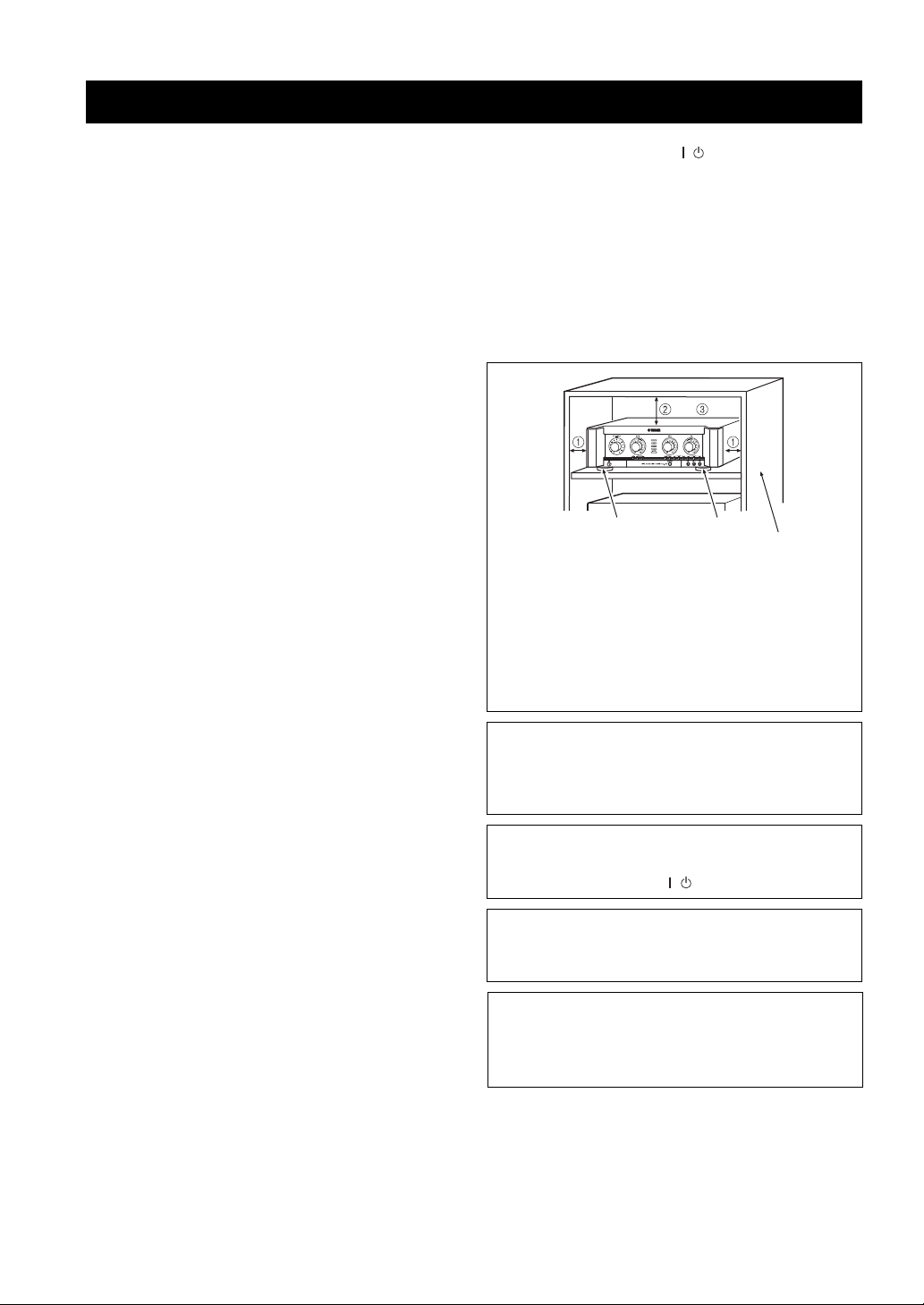
foot foot
The following rack size measurements must be adhered to:
rack
12 The ventilation space on the top, left and right of this
unit; more than 10 cm (3-15/16”)
3 The ventilation space on the back of this unit; more
than 20 cm (7-7/8”)
4 Do not remove the feet.
WARNING
TO REDUCE THE RISK OF FIRE OR ELECTRIC
SHOCK, DO NOT EXPOSE THIS UNIT TO RAIN
OR MOISTURE.
As long as this unit is connected to the AC wall outlet,
it is not disconnected from the AC power source even
if you turn off this unit by / switch.
CAUTION
Danger of explosion if battery is incorrectly replaced.
Replace only with the same or equivalent type.
CAUTION
Use of controls or adjustments or performance of
procedures other than those specified herein may result
in hazardous radiation exposure.
i En

INTRODUCTION
HANDLING PRECAUTIONS ..............................2
BEFORE CONNECTING ..................................... 2
PREPARATION
NAMES OF PARTS AND THEIR FUNCTIONS
.............................................................................. 3
OPERATION
SYSTEM CONNECTIONS ................................... 6
CONNECTIONS .................................................... 7
CONFIGURATION DIAGRAM ........................ 10
REMOTE CONTROL ......................................... 11
GENERAL OPERATION ................................... 13
SETUP MODE...................................................... 14
ADDITIONAL INFORMATION
TROUBLESHOOTING....................................... 17
MAINTENANCE ................................................. 18
AFTER-SALES SERVICING ............................. 18
KARAOKE ETIQUETTE ................................... 18
COPYRIGHT ....................................................... 18
SPECIFICATIONS .............................................. 19
CONTENTS
PREPARATIONINTRODUCTION
OPERATION
INFORMATION
ADDITIONAL
1 En
English

INTRODUCTION
Thank you for your purchase of the Yamaha KMA-1080/KMA-980 Digital Karaoke Mixing Amplifier.
This document is the owner’s manual for both KMA-1080 and KMA-980. Model names are given where the details of
functions are unique to each model. Illustrations for KMA-1080 are mainly used for explanations.
Before using this unit, be sure to read this manual so that you can take full advantage of the features of this unit.
After you finish reading, keep this manual in a safe place in case you need it in the future. The manual should be very
helpful in understanding the Digital Karaoke Mixing Amplifier and solving any difficulties that may arise during use.
HANDLING PRECAUTIONS
■ Do not install the unit in the following
locations:
• In places exposed to direct sunlight or near heat
sources, such as a radiator.
• In places where heat cannot escape due to poor
ventilation, or are very humid or dusty.
• On a sloping surface or exposed to excessive vibration.
BEFORE CONNECTING
■ Connection precautions
• Be sure to switch off the power of the relevant
equipment before making any connection.
• The white input/output jacks of the amplifier are
designed for the left channel, while the red input/output
jacks are for the right channels. Be sure to connect the
cords without making a mistake in the color codes for
the left and right channels.
• Insert the plugs of the connection cords securely into
the jacks. If the connection is incomplete, there may be
no sound produced or noise may be generated.
• When unplugging the power cable from the AC wall
outlet, be sure to hold the plastic molding of the plug
itself and pull.
• For KMA-1080, set IMPEDANCE SELECTOR on the
rear panel before turning on the unit. Refer to
“IMPEDANCE SELECTOR” on page 7.
• In places which may be exposed to rain, such as near a
window.
• In places which may be exposed to soot, vapor or heat,
such as near cooking facilities.
2 En
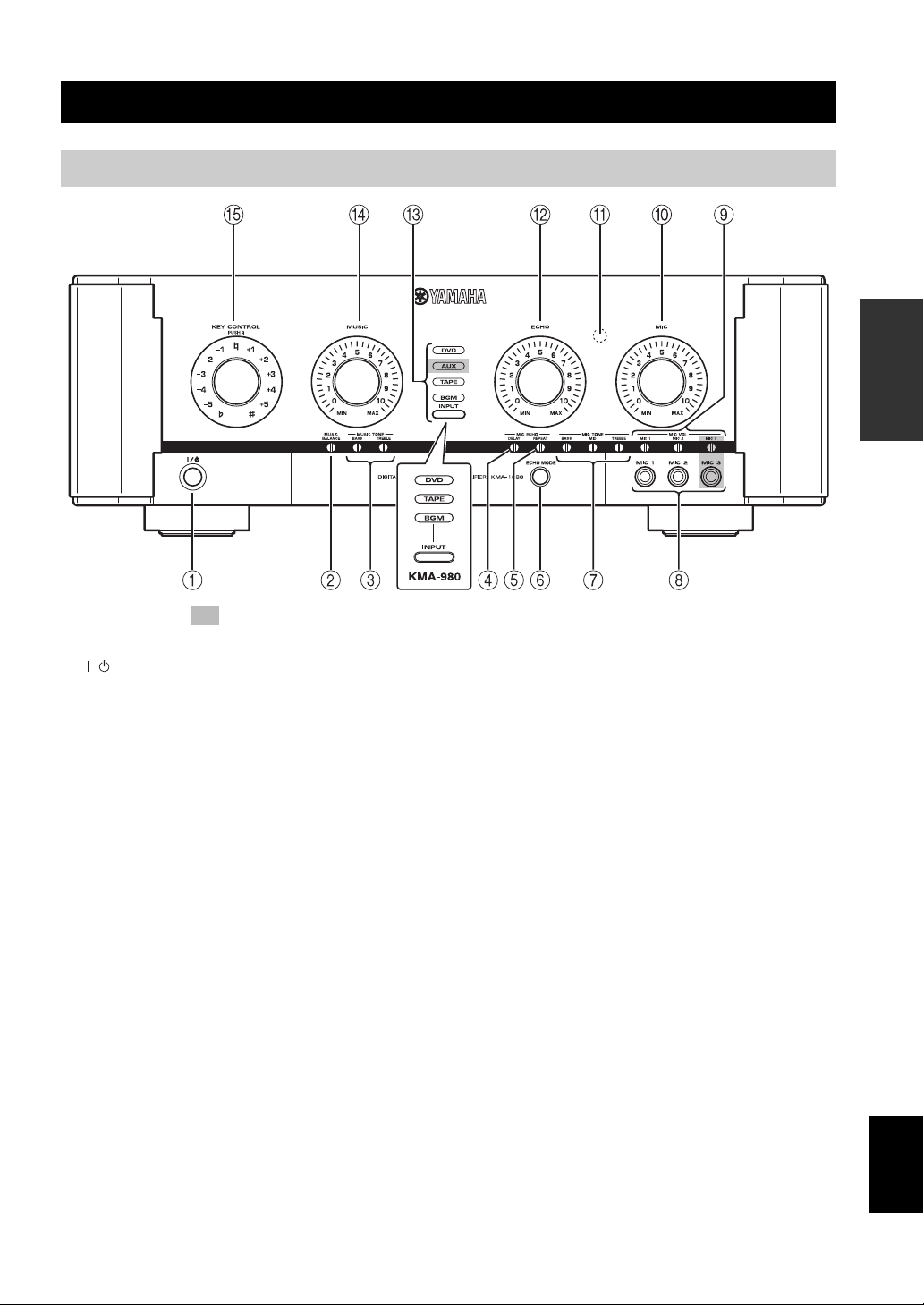
PREPARATION
Front panel
NAMES OF PARTS AND THEIR FUNCTIONS
PREPARATION
The shaded part ( ) is provided for KMA-1080 only.
1 / (power on/off)
Turn the power on/off.
2 MUSIC BALANCE
Adjust the volume balance.*
3 MUSIC TONE (BASS/TREBLE)
Adjust the low/high frequency response.*
4 MIC ECHO DELAY
Adjust the delay time between echoes.*
5 MIC ECHO REPEAT
Adjust the amount of feedback.*
6 ECHO MODE
Select NORMAL, WIDE (stereo) or SPACIOUS** echo.
SPACIOUS echo is an effect that produces both
NORMAL and WIDE echo with a time lag. The LED
lights up in amber/green** when WIDE/SPACIOUS**
echo is selected.
ECHO MODE is reset after the played song has finished
when the ECHO MODE auto reset is set to on. Refer to
“ECHO MODE auto reset” on page 14. The unit assumes
songs have finished when over 4 seconds of silence occurs.
7 MIC TONE (BASS/MID/TREBLE)
Adjust the low/middle/high frequency response of
microphones.*
8 MIC jacks (1/2/3**)
Connect microphones to these jacks.
9 MIC VOL (1/2/3**)
Adjust the microphone input level.*
0 MIC
Adjust the overall volume of all microphones.
A Remote sensor
This sensor receives signals from the remote control.
B ECHO
Adjust the amount of echo.
C INPUT/Input source indicators (DVD/AUX**/
TAPE/BGM)
INPUT is not available in the default setting.
To activate INPUT, refer to “Input mode” on page 14.
Input source indicators indicate the input source currently
active.
D MUSIC
Adjust the volume of the music source.
E KEY CONTROL
To transpose the key of the played music, rotate this
control. The key can be changed in halftone steps in 5
steps; either higher or lower. To reset the key to the
natural key, press this control. If over 4 seconds of silence
occurs, the unit assumes the played song has finished and
resets the key to natural.
* Use a flathead screwdriver to adjust.
** KMA-1080 only
English
3 En
NAMES OF PARTS AND THEIR FUNCTIONS
Rear panel
The shaded part ( ) is provided for KMA-1080 only.
For details on component connection, refer to “SYSTEM
CONNECTIONS” on page 6.
1 BALANCED MIC INPUT jacks (1/2)
Connect microphones to these jacks.
These are balanced inputs and each connects to the same
circuit MIC 1 and 2 on the front panel.
2 DVD audio input jacks
Connect to the output jacks of KARAOKE equipment or
DVD player.
3 AUX audio input jacks*
Connect to the output jacks of a TAPE player, VCR, etc.
4 TAPE audio input jacks
Connect to the output jacks of a TAPE player, VCR, etc.
5 TAPE audio output jacks
Connect to the input jacks of a TAPE player, VCR, etc.
6 BGM audio input jacks
Connect to the output jacks of the source component of
background music.
7 SUBWOOFER jack without low-pass filter
Connect to the input jack of the subwoofer with a lowpass filter. This jack outputs the monaural signal directly.
8 SUBWOOFER jack with low-pass filter
Connect to the input jack of the subwoofer.
9 PRE OUT jacks
Connect to the input jacks of the extension power
amplifier.
0 IMPEDANCE SELECTOR*
Refer to “IMPEDANCE SELECTOR” on page 7.
A REMOTE jack
Connect to an external remote control.
Refer to “Connecting an external remote control” on page
8.
B VIDEO INPUT jacks
Connect to the input jack of the video output of a DVD,
AUX*, or background video player or video camera, etc.
* KMA-1080 only
4 En
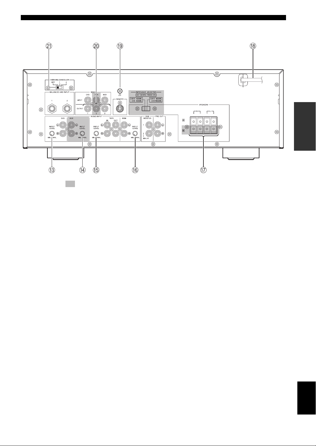
The shaded part ( ) is provided for KMA-1080 only.
NAMES OF PARTS AND THEIR FUNCTIONS
PREPARATION
C DVD INPUT LEVEL
Adjust the balance of the DVD input level with respect to
other inputs (AUX*, TAPE, BGM).
D AUX INPUT LEVEL*
Adjust the balance of the AUX input level with respect to
other inputs (DVD, TAPE, BGM).
E TAPE INPUT LEVEL
Adjust the balance of the TAPE input level with respect to
other inputs (DVD, AUX*, BGM).
F BGM INPUT LEVEL
Adjust the balance of the BGM input level with respect to
other inputs (DVD, AUX*, TAPE).
G SPEAKERS (Speaker system terminal(s))
Connect to the speaker system(s).
For KMA-980, only one speaker system is available.
H Power cable
Plug this cable into an AC wall outlet after all other
connections are complete.
I Signal ground terminal
Connect this terminal if a humming noise is emitted when
connecting this amplifier.
J VIDEO OUTPUT jacks
Connect to the video input of the monitor.
K HOWLING CANCELLER
Set this switch to reduce the room's acoustic feedback. To
reduce the feedback, select 1. If reduction in feedback is
not sufficient, select 2. Select OFF to cancel feedback
reduction.
* KMA-1080 only
English
5 En
 Loading...