

Page 1

Page 2

SPECIAL MESSAGE SECTION
This product utilizes batteries or an external power supply (adapter). DO
NOT connect this product to any power supply or adapter other than one
described in the manual, on the name plate, or specifically recommended by Yamaha.
WARNING:
walk on, trip over ,or roll anything over power or connecting cords of any
kind. The use of an extension cord is not recommended! If you must use
an extension cord, the minimum wire size for a 25’ cord (or less ) is 18
AWG. NOTE: The smaller the AWG number ,the larger the current handling capacity. For longer extension cords, consult a local electrician.
This product should be used only with the components supplied or; a
cart, rack, or stand that is recommended by Yamaha. If a cart, etc., is
used, please observe all safety markings and instructions that accompany the accessory product.
Do not place this product in a position where anyone could
SPECIFICATIONS SUBJECT TO CHANGE:
The information contained in this manual is believed to be correct at the
time of printing. However, Yamaha reserves the right to change or modify
any of the specifications without notice or obligation to update existing
units.
This product, either alone or in combination with an amplifier and headphones or speaker/s, may be capable of producing sound levels that
could cause permanent hearing loss. DO NOT operate for long periods
of time at a high volume level or at a level that is uncomfortable. If you
experience any hearing loss or ringing in the ears, you should consult an
audiologist.
IMPORTANT: The louder the sound, the shorter the time period before
damage occurs.
Some Yamaha products may have benches and / or accessory mounting fixtures that are either supplied with the product or as optional
accessories. Some of these items are designed to be dealer assembled
or installed. Please make sure that benches are stable and any optional
fixtures (where applicable) are well secured BEFORE using.
Benches supplied by Yamaha are designed for seating only. No other
uses are recommended.
NOTICE:
Service charges incurred due to a lack of knowledge relating to how a
function or effect works (when the unit is operating as designed) are not
covered by the manufacturer’s warranty, and are therefore the owners
responsibility. Please study this manual carefully and consult your dealer
before requesting service.
ENVIRONMENTAL ISSUES:
Yamaha strives to produce products that are both user safe and environmentally friendly. We sincerely believe that our products and the production methods used to produce them, meet these goals. In keeping with
both the letter and the spirit of the law, we want you to be aware of the
following:
Battery Notice:
This product MAY contain a small non-rechargeable battery which (if
applicable) is soldered in place. The average life span of this type of battery is approximately five years. When replacement becomes necessary,
contact a qualified service representative to perform the replacement.
This product may also use “household” type batteries. Some of these
may be rechargeable. Make sure that the battery being charged is a
rechargeable type and that the charger is intended for the battery being
charged.
When installing batteries, do not mix batteries with new, or with batteries
of a different type. Batteries MUST be installed correctly. Mismatches or
incorrect installation may result in overheating and battery case rupture.
Warning:
Do not attempt to disassemble, or incinerate any battery. Keep all batteries away from children. Dispose of used batteries promptly and as regulated by the laws in your area. Note: Check with any retailer of
household type batteries in your area for battery disposal information.
Disposal Notice:
Should this product become damaged beyond repair, or for some reason
its useful life is considered to be at an end, please observe all local,
state, and federal regulations that relate to the disposal of products that
contain lead, batteries, plastics, etc. If your dealer is unable to assist
you, please contact Yamaha directly.
NAME PLATE LOCATION:
The name plate is located on the top panel of the product. The name
plate lists the product’s model number, power requirements, and other
information. The serial number is located on the name plate. Please
record the model number, serial number, and date of purchase in the
spaces provided below, and keep this manual as a permanent record of
your purchase.
Model
Serial No.
Purchase Date
92-BP
(others)
PLEASE KEEP THIS MANUAL
Page 3
Water warning
Fire warning
If you notice any abnormality
Location
PRECAUTIONS
PLEASE READ CAREFULLY BEFORE PROCEEDING
* Please keep this manual in a safe place for future reference.
WARNING
Always follow the basic precautions listed below to avoid the possibility of serious injury or even death from
electrical shock, short-circuiting, damages, fire or other hazards. These precautions include, but are not limited to,
the following:
Power supply/AC power adaptor
• Only use the voltage specified as correct for the instrument. The required
voltage is printed on the name plate of the instrument.
• Use the specified adaptor (PA-5D or an equivalent recommended by Yamaha)
only. Using the wrong adaptor can result in damage to the instrument or
overheating.
• Check the electric plug periodically and remove any dirt or dust which may
have accumulated on it.
• Do not place the AC adaptor cord near heat sources such as heaters or
radiators, and do not excessively bend or otherwise damage the cord, place
heavy objects on it, or place it in a position where anyone could walk on, trip
over, or roll anything over it.
Do not open
• Do not open the instrument or attempt to disassemble the internal parts or
modify them in any way. The instrument contains no user-serviceable parts. If
it should appear to be malfunctioning, discontinue use immediately and have
it inspected by qualified Yamaha service personnel.
• Do not expose the instrument to rain, use it near water or in damp or wet
conditions, or place containers on it containing liquids which might spill into
any openings.
• Never insert or remove an electric plug with wet hands.
• Do not put burning items, such as candles, on the unit.
A burning item may fall over and cause a fire.
• If the AC adaptor cord or plug becomes frayed or damaged, or if there is a
sudden loss of sound during use of the instrument, or if any unusual smells or
smoke should appear to be caused by it, immediately turn off the power
switch, disconnect the adaptor plug from the outlet, and have the instrument
inspected by qualified Yamaha service personnel.
English
CAUTION
Always follow the basic precautions listed below to avoid the possibility of physical injury to you or others, or
damage to the instrument or other property. These precautions include, but are not limited to, the following:
Power supply/AC power adaptor
• When removing the electric plug from the instrument or an outlet, always hold
the plug itself and not the cord.
• Unplug the AC power adaptor when not using the instrument, or during
electrical storms.
• Do not connect the instrument to an electrical outlet using a multipleconnector. Doing so can result in lower sound quality, or possibly cause
overheating in the outlet.
• Do not expose the instrument to excessive dust or vibrations, or extreme cold
or heat (such as in direct sunlight, near a heater, or in a car during the day) to
prevent the possibility of panel disfiguration or damage to the internal
components.
• Do not use the instrument in the vicinity of a TV, radio, stereo equipment,
mobile phone, or other electric devices. Otherwise, the instrument, TV, or
radio may generate noise.
• Do not place the instrument in an unstable position where it might
accidentally fall over.
• Before moving the instrument, remove all connected adaptor and other cables.
• Use only the rack specified for the instrument. When attaching the rack, use
the provided screws only. Failure to do so could cause damage to the internal
components or result in the instrument falling over.
(3)-7
1/2
3
Page 4
Handling caution
Connections
• Before connecting the instrument to other electronic components, turn off the
power for all components. Before turning the power on or off for all
components, set all volume levels to minimum. Also, be sure to set the
volumes of all components at their minimum levels and gradually raise the
volume controls while playing the instrument to set the desired listening level.
Maintenance
• When cleaning the instrument, use a soft, dry cloth. Do not use paint thinners,
solvents, cleaning fluids, or chemical-impregnated wiping cloths.
English
Yamaha cannot be held responsible for damage caused by improper use or modifications to the instrument, or data that is lost or destroyed.
Always turn the power off when the instrument is not in use.
Even when the power switch is in the “STANDBY” position, electricity is still flowing to the instrument at the minimum level. When you are not using the instrument for a
long time, make sure you unplug the AC power adaptor from the wall AC outlet.
• Do not insert a finger or hand in any gaps on the instrument.
• Never insert or drop paper, metallic, or other objects into the gaps on the
panel. If this happens, turn off the power immediately and unplug the power
cord from the AC outlet. Then have the instrument inspected by qualified
Yamaha service personnel.
• Do not place vinyl, plastic or rubber objects on the instrument, since this
might discolor the panel or keyboard.
• Do not rest your weight on, or place heavy objects on the instrument, and do
not use excessive force on the buttons, switches or connectors.
• Do not operate the instrument for a long period of time at a high or
uncomfortable volume level, since this can cause permanent hearing loss. If
you experience any hearing loss or ringing in the ears, consult a physician.
(3)-7
2/2
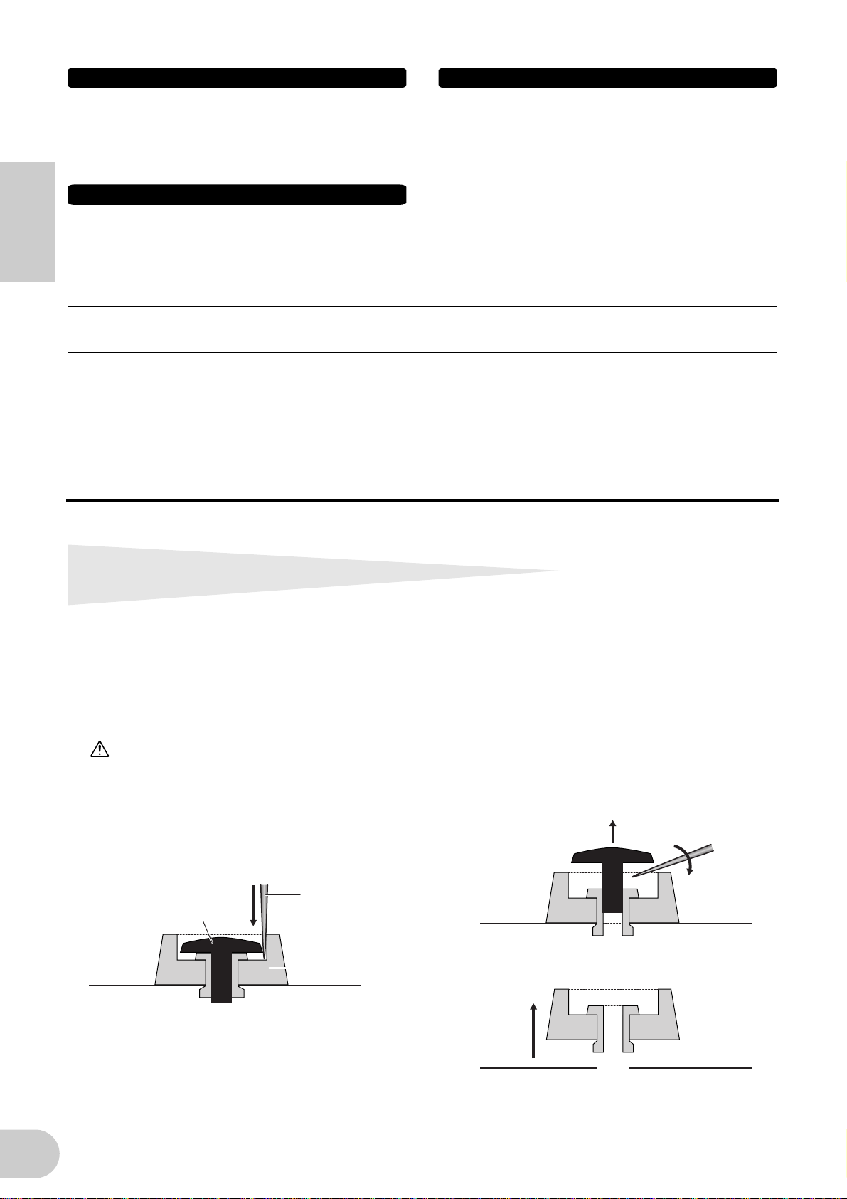
Removing rubber stoppers for rack
mount installation
The i88X has four removable rubber stoppers. If the i88X does not fit in your rack mount cabinet
because the stoppers hit against another device, remove the stoppers as described below.
Before removing the stoppers, make sure you have a sharp, thin tool — such as a safety pin or straightened paper clip.
CAUTION
Do not use any tool that easily snaps or bends, such as a toothpick or thin wire.
1. Turn the i88X upside down.
2. Insert the tool between the rubber stopper
and the plastic rivet (as shown).
3. Pull the rivet up and out of the panel.
4
Rivet
Sharp tool
Rubber stopper
4. Pull out the rubber stoppers.
To re-attach the removed stoppers, reverse the
procedure above, inserting the rivets perpendicularly.
Page 5
•
•
•
•
•
•
•
•
•
•
•
•
Introduction
Thank you for purchasing the Yamaha i88X Audio/MIDI Interface.
Connecting the i88X to a computer expands music production environments that utilize an audio
sequencer on the computer.
The i88X supports mLAN, a digital music network based on the IEEE1394 high performance serial
bus and data protocol. The i88X makes it easy to construct sophisticated networks for IEEE1394
audio and MIDI signals without having to re-configure complicated cabling, as was necessary on
earlier conventional systems.
In order to take full advantage of the i88X’s functionality, please read this manual carefully. After
reading this manual, please keep it available for future reference.
Package Contents
English
i88X unit
Tools for i88X/mLAN16E (CD-ROM)
Plug-in Effect (CD-ROM)
mLAN cable (IEEE1394 cable) (6-pin to 6-pin)
AC Adaptpr: PA-5D
Owner’s Manual (this document)
Tools for i88X/mLAN16E Installation Guide
User’s Card (containing the serial number for the included Plug-in software effects)
About the included CD-ROM
The i88X is shipped with a CD-ROM that contains software that is useful when used in conjunction with the i88X. This software includes drivers that are required to connect the i88X to a computer. It also includes software that enables you to route audio and MIDI signals between mLAN
devices and plug-in effects. For more information, refer to the separate “Tools for i88X/mLAN16E
Installation Guide” and the software online manuals.
Yamaha is not responsible for damage caused by improper use or modifications to the
device or for data that is lost or destroyed.
The illustrations and LCD screens shown in this Owner’s Manual are for instructional purposes
only and may appear somewhat different from those on your device.
MIDI is a registered trademark of the Association of Musical Electronics Industry (AMEI).
mLAN is a trademark of Yamaha Corporation.
Company and product names in this Owner’s Manual are the trademarks or registered trade-
marks of their respective owners.
5
Page 6

■
■
•
Features
Fast data transfer via mLAN
Connecting the i88X to a computer and other mLAN devices via IEEE1394 (FireWire/i.LINK) cables
enables you to transfer multi-channel audio data and multi-port MIDI signals to and from a computer-based DAW (Digital Audio Workstation) and connected mLAN devices (at a transfer rate of
400Mbps [S400]).
Up to 18 audio channel I/O
English
The i88X features two MIC/LINE inputs and six LINE inputs. Inputs 1 and 2 feature two sonically
transparent mic preamps (derived from DM2000) and phantom power, and accept both XLR
and TRS phone plugs. Inputs 3-8 accept TRS phone plugs (pages 8 and 11).
•
Input 1 also features a HI-Z (high impedance) jack to connect high-impedance instruments, such
as guitar or bass (page 8).
•
The Insert I/O jacks enable you to connect an external effects processor (page 11).
•
The i88X also features a sampling rate converter that supports sampling frequencies from
44.1 kHz through 96 kHz. It also features coaxial DIGITAL STEREO IN and OUT jacks and the
optical IN and OUT jacks that are switchable between STEREO and ADAT.
•
The MIDI IN and OUT ports enable you to connect external MIDI devices in the mLAN system
(page 11).
•
The i88X can process up to 18-channel input and output data when running at a sampling frequency of 48 kHz or 44.1 kHz, and up to 14-channel input and output data when running at a
sampling frequency of 96 kHz or 88.2 kHz.
■
Audio Characteristics
•
Compatible sampling frequencies: 44.1 kHz, 48 kHz, 88.2 kHz, 96 kHz
•
Linear 24-bit, 128-times (at a sampling frequency of 48 kHz or 44.1 kHz) or 64-times (at a sampling frequency of 96 kHz or 88.2 kHz) oversampling A/D and D/A converters
•
Frequency response: 20 Hz – 20 kHz, Standard dynamic range: 110 dB
■
Direct Monitoring Function
•
Enables you to monitor the sound being recorded to the DAW without latency (sound delay)
(page 17).
■
Integrated Package Containing Plug-in Effects
•
Four VST/AU plug-in effects, including equalizer, vocal and mastering effects, etc.
Table of Contents
Removing rubber stoppers for rack mount installation....................................................... 4
Introduction .......................................................................................................................... 5
Package Contents.................................................................................................................. 5
Features ................................................................................................................................. 6
Fundamentals of mLAN......................................................................................................... 7
Operational Flow for Sound Output..................................................................................... 7
Names and Functions............................................................................................................ 8
Front Panel.................................................................................................................... 8
Rear Panel .................................................................................................................... 11
Turning the Power to the i88X and Connected Devices On and Off ................................. 12
Connecting External Devices ............................................................................................... 13
Connecting Musical Instruments and Microphones and Adjusting the Input Level.......... 16
Direct Monitoring ................................................................................................................ 17
System Examples.................................................................................................................. 18
Making mLAN Connections ................................................................................................. 20
LED Indicators ...................................................................................................................... 21
Troubleshooting................................................................................................................... 22
Specifications ....................................................................................................................... 25
6
Page 7

Fundamentals of mLAN
mLAN is a digital network for music that was developed based on IEEE1394, an industry-standard
high-performance data communications protocol.
Digital music environments that do not feature mLAN require dozens of cables for various devices
and purposes, including MIDI cables and audio cables to route MIDI and audio signals. If you wish
to make changes to such systems, you must physically disconnect and re-connect these cables.
For example, adding another synthesizer to a system requires two MIDI cables and two or more
cables for audio (for stereo equipment). Making the appropriate connections may require special
knowledge of inputs, outputs, stereo settings, and perhaps connector impedance.
The larger the system, the more complicated and expensive these connections become, increasing
the likelihood of errors and difficulties. It takes time and effort to investigate such errors and their
underlying causes. You may have already experienced the unpleasantness of tracking various cables
through a spider’s web of connections.
English
mLAN simplifies cable connections by using only one type of IEEE1394 cable, thus enabling you to
configure extremely sophisticated systems. There is no need to re-patch cables to change routings
of MIDI and audio signals between mLAN devices.
Operational Flow for Sound Output
1. Install Tools for i88X/mLAN16E.
........... See “Installing the Software” in the Installation Guide.
2. Connect the computer and mLAN devices using the IEEE1394 cables.
........... See page 13.
3. Turn on mLAN Manager (Windows only).
........... See “Confirming the installation” in the Installation Guide.
4. To connect a computer to a single mLAN device directly, first start mLAN Auto Connector.
To connect a computer to multiple mLAN devices, start mLAN Graphic Patchbay.
........... See page 20
5. Configure connections in mLAN Auto Connector or mLAN Graphic Patchbay.
........... Using Auto Connector: See “Connecting a Computer to an mLAN device via
mLAN” in the Installation Guide.
........... Using Graphic Patchbay: See “mLAN Connection Settings” in the Graphic Patch-
bay Online Manual.
6. Specify the audio and MIDI inputs and outputs, following the owner’s manual for your
DAW, audio sequencer and connected devices.
For subsequent steps, refer to the owner’s manual for the software and connected devices.
NOTE
In this manual, setting up audio, MIDI, and wordclock routings is referred as “mLAN connection.”
7
Page 8
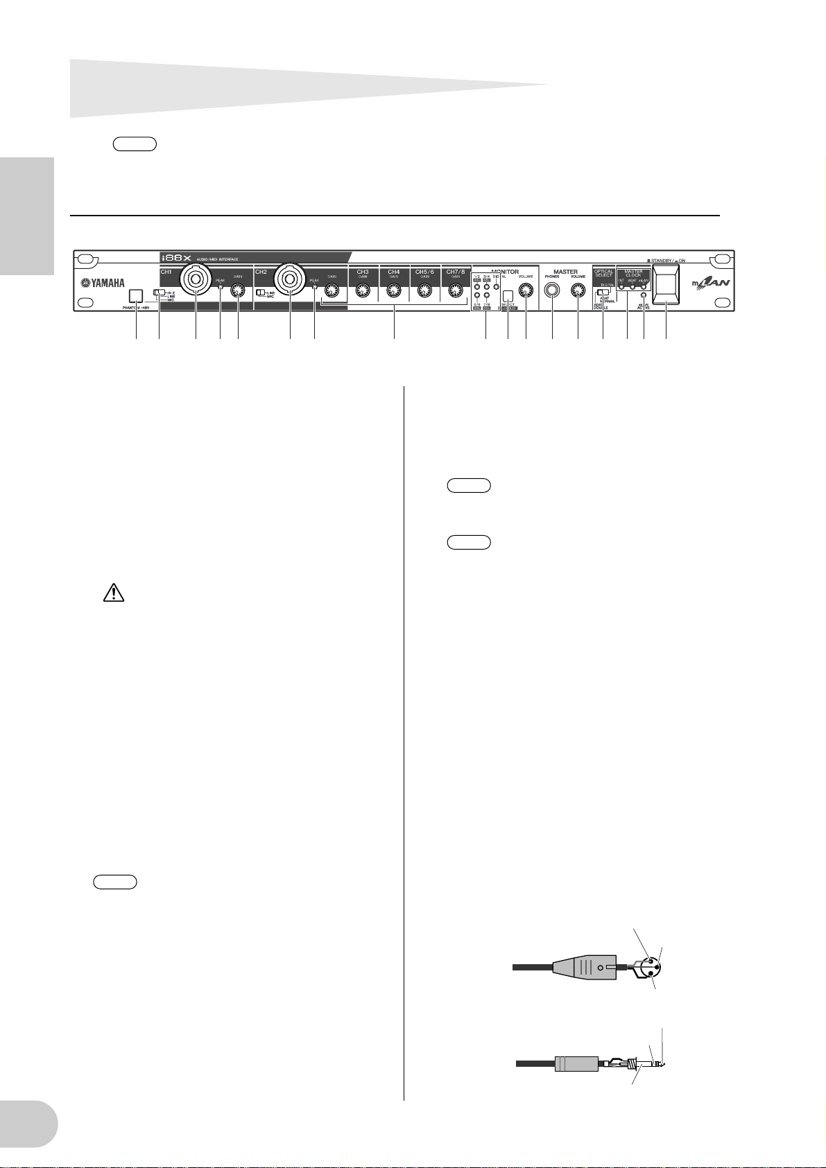
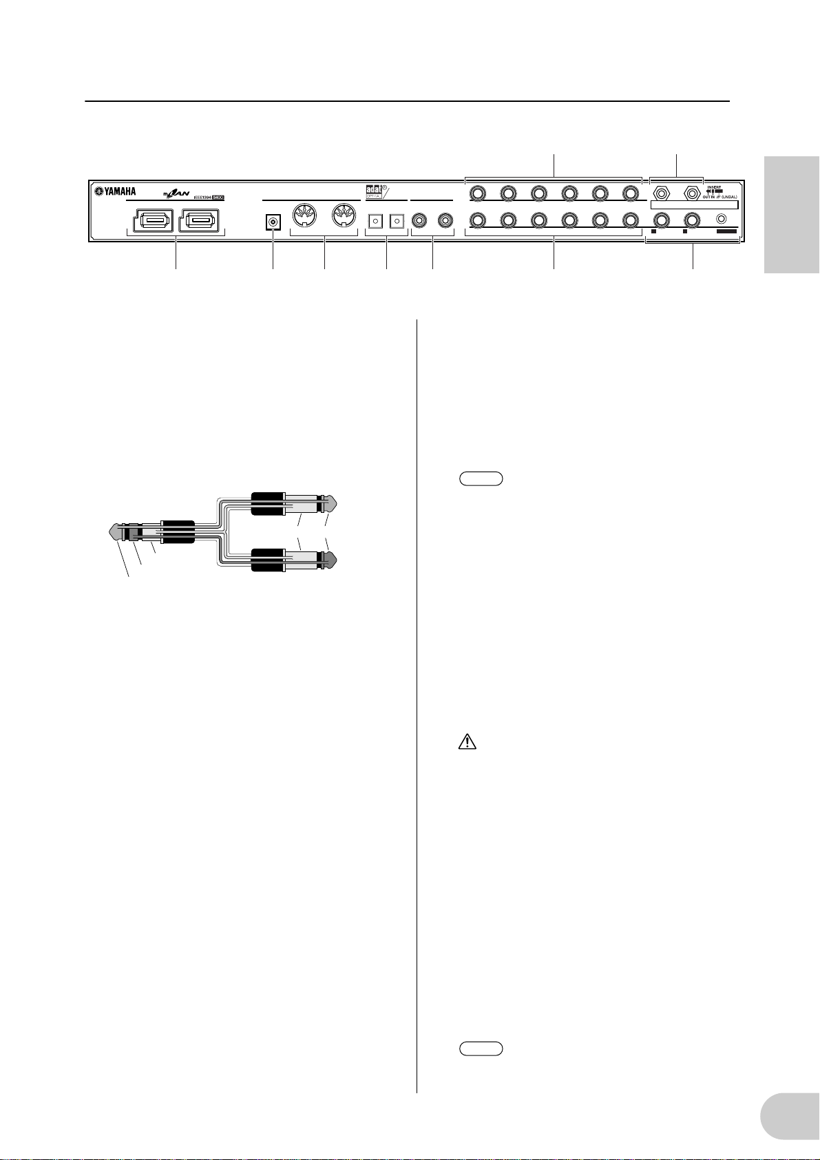
Names and Functions
NOTE
Numbers indicated to the left of the names (
numbers indicated in the block diagram on back cover page.
Front Panel
English
1 2 3 4 3 4 5 76 8 9 0 A CB D5
1 [PHANTOM +48V] switch
This switch supplies +48 V phantom power to
XLR and TRS phone compatible INPUT jacks 1
and 2 (3). Note that phantom power will not
be supplied if you have connected an external
device to the INPUT 1 and 2 TRS phone jacks
(3). Turn this switch on if you are connecting a
condenser microphone that requires external
+48 V power to INPUT jack 1 or 2 (3). When
the switch is turned on, the switch indicator
lights up.
• Be sure to turn this switch off if you
connect a device that does not require
an external power supply to the INPUT
1 or 2 XLR jack. Otherwise, phantom
power will be supplied to the device,
possibly causing damage to the
device.
• If you connect a device that requires
an external power supply, first connect
the device to an XLR connector, then
turn on the phantom power.
• When phantom power is turned on,
power will be supplied to both INPUT
jacks 1 and 2.
• Phantom power is not supplied to TRS
phone connectors.
NOTE
2 [(HI-Z)/LINE/MIC] switch
This switch enables you to select high-impedance input, mic input, or line input for XLR and
TRS phone compatible INPUT jacks 1 and 2
3).
(
HI-Z: Use this setting to connect a high-
If the [HI-Z/LINE/MIC] switch (2) is
set to HI-Z, phantom power is not supplied to INPUT jack 1 (3).
impedance musical instrument, such
as a guitar with passive pickups or a
bass guitar.
-
,
-
,
-
1
5
7
A
LINE: Use this setting to connect a line-level
instrument, such as a synthesizer, keyboard, or audio equipment.
MIC: Use this setting to connect a mic-level
device.
NOTE
NOTE
Select HI-Z, LINE, or MIC for INPUT
jack 1. Select LINE or MIC for INPUT
jack 2.
When the [HI-Z/LINE/MIC] switch is
set to HI-Z, phantom power is not supplied to INPUT jack 1 (3).
, and M) correspond the
E
K
3 XLR/TRS Phone Compatible INPUT 1 and
2 jacks
These balanced input jacks accept both XLR-331 and TRS phone (1/4") plugs and can be used
for high-impedance, line or mic inputs. You can
also connect musical instruments with unbalanced outputs, such as a synthesizer or rhythm
machine. Setting the [HI-Z/LINE/MIC] switch
(2) appropriately enables you to connect a
high-impedance instrument, line-out instrument or microphone to INPUT jack 1. Setting
the [LINE/MIC] switch (2) appropriately
enables you to connect a line-out instrument or
microphone to INPUT jack 2.
Nominal input levels:
MIC: –60 dBu to –16 dBu
LINE: –34 dBu to +10 dBu
HI-Z: –56 dBu to –12 dBu
1 (Ground)
Male XLR plug
1/4"TRS phone plug
Ring (Cold)
3 (Cold)
2 (Hot)
Tip (Hot)
Sleeve (Ground)
8
Page 9

4 [PEAK] indicators
A [PEAK] indicator lights up red if the input signal that has passed through the [GAIN] control
(5) reaches a level 3 dB below the clipping
point. In order to record at the optimal level,
adjust the [GAIN] control (5) so that this indicator flickers briefly when you play at your loudest level.
5 [GAIN] controls
These controls enable you to adjust the input
sensitivity (head amp gain) of INPUT jacks 1, 2,
3, 4, 5/6 and 7/8. (page 16)
Setting range:
Ch 1 & 2
MIC: –16 dBu to –60 dBu
LINE: +10 dBu to –34 dBu
HI-Z,: –12 dBu to –56 dBu
Ch 3–8 +10 dBu to –20 dBu
6 MONITOR [1/2 (44k)] - [7/8 (96k)] indi-
cators
When the monitoring channels selected via the
[SELECT] switch (7) output signals, the corresponding [1/2] - [7/8] indicators in the MONITOR section light up red.
When you press and hold down the [SELECT]
switch for one second or longer, the indicator
for the current operating sampling frequency
(44k, 48k, 88k, or 96k) flashes red.
NOTE
The [44k] indicator represents a sam-
pling frequency of 44.1 kHz, and the
[88k] indicator represents a sampling
frequency of 88.2 kHz.
7 MONITOR [SELECT] switch
This switch enables you to select a monitoring
channel that outputs signals from the MASTER
OUT L and R jacks on the rear panel (page 17).
Press the switch briefly (less than one second)
repeatedly to select monitoring channels in the
following sequence:
Off → CH1/2 → CH3/4 → CH5/6 → CH7/8 →
DIGITAL STEREO → Off
The MONITOR indicator (6) for the selected
channels lights up.
Also, when you press and hold down this switch
for one second or longer, the MONITOR indicator for the current operating sampling frequency flashes red.
NOTE
NOTE
You cannot route a signal input from the
ADAT NORMAL/DOUBLE jack to a
monitoring channel.
The monitoring channel selection is
reset to Off when you turn the power
to the i88X off and then back on.
8 [MONITOR VOLUME] control
This control adjusts the signal volume level of
the monitoring channel selected via the
[SELECT] switch (7). The monitoring signal is
output from the OUTPUT/MASTER 1/L and 2/R
jacks and MASTER PHONES jack (page 17).
9 MASTER PHONES jack
You can connect a set of stereo headphones to
this stereo phone jack. The signals output from
the OUTPUT/MASTER 1/L and 2/R jacks are also
output from this jack.
0 [MASTER VOLUME] control
This control adjusts the level of the signals output from the OUTPUT/MASTER 1/L and 2/R
jacks.
NOTE
To output mLAN INPUTS audio level
signals from the OUTPUT/MASTER 1/
L and 2/R jacks (G) at line level
(+4 dBu), turn the [MASTER VOLUME] control all the way to the right.
The signals will be output at the same
level as those output from the OUTPUT 3-8 jacks.
A [OPTICAL SELECT] switch
This switch enables you to select the function of
the OPTICAL IN and OUT jacks on the rear
panel. For more information, refer to “About
the OPTICAL SELECT switch, MASTER CLOCK
indicator, and wordclock master” on page 10.
ADAT DOUBLE:
Select this option for a high sampling rate
(88.2 kHz or 96 kHz). The OPTICAL IN and
OUT jacks function as ADAT IN and OUT jacks
that receive and transmit digital audio signals
of up to four channels at the same time. A single optical cable combines eight-channel,
44.1 kHz or 48 kHz digital audio signals into
four-channel, 88.2 kHz or 96 kHz digital audio
signals.
ADAT NORMAL:
Select this option for a normal sampling rate
(44.1 kHz or 48 kHz). The OPTICAL IN and
OUT jacks function as ADAT IN and OUT jacks
that receive and transmit up to eight-channel
digital audio data. This is the standard ADAT
format.
DIGITAL:
The OPTICAL IN and OUT jacks function as a
digital stereo input and output.
NOTE
NOTE
If you select DIGITAL, the COAXIAL IN
jack is disabled.
Before you select ADAT DOUBLE,
make sure that your ADAT-compatible
device supports ADAT DOUBLE
mode.
B MASTER CLOCK indicators
These indicators light up to indicate the wordclock to which the i88X is locking. For more
information, refer to “About the OPTICAL
SELECT switch, MASTER CLOCK indicator, and
English
9
Page 10
wordclock master” on page 10. You can select
the sampling frequency using mLAN Auto Connector or mLAN Graphic Patchbay (page 20).
INT: The i88X uses the internal clock at
44.1 kHz.
ADAT: The i88X uses the incoming ADAT sig-
nal as the master clock.
mLAN: The i88X uses the incoming mLAN
signal as the master clock.
Lit green: The i88X locks to the word-
English
Flashing green: The i88X is not locking to the
C [mLAN ACTIVE] indicator
This indicator lights up when the i88X is operating.
The indicator turns off when an error occurs
during an mLAN operation.
When you click the [ID] button in mLAN Auto
Connector or mLAN Graphic Patchbay
clock master.
wordclock master.
(page 20) to identify the corresponding mLAN
device in the network, the indicator flashes.
NOTE
The indicator also lights up if an mLAN
cable is not connected to the unit.
D [STANDBY/ON] switch
This switch turns the power to the unit on
or off (Standby).
CAUTION
Be sure to follow the procedures described in
“Turning the Power to the i88X and Connected
Devices On and Off” on page 12 when you
turn the power to the i88X on or off.
Even when the switch is in the STANDBY position, a small amount of electricity is still flowing
to the unit. When you do not plan to use the
i88X for an extended period of time, be sure to
unplug the AC power adapter from the AC outlet.
■ About the OPTICAL SELECT Switch, MASTER CLOCK Indicators, and Wordclock
The function of the OPTICAL IN and OUT jacks (J) specified by the [OPTICAL SELECT] switch (7), and
which MASTER CLOCK indicator (B) will light up, varies depending on which mLAN device in the mLAN
network is being used as the wordclock master.
1. When the wordclock master in an mLAN
network is an mLAN device other than
the computer and i88X (that is, when the
i88X is using the incoming mLAN signal
as the master clock):
MASTER CLOCK indicators
The [mLAN] indicator lights up.
[OPTICAL SELECT] switch
DIGITAL:
The OPTICAL IN and OUT jacks function as a
digital stereo input and output.
ADAT NORMAL or ADAT DOUBLE:
The sampling frequency in the mLAN network
determines the operating mode (NORMAL or
DOUBLE). You can select either mode when
the OPTICAL IN and OUT jacks are used as the
ADAT input and output.
2. When the i88X is referencing the incoming ADAT master clock signal and the
i88X has been specified as the clock master in the mLAN network (that is, when
the i88X is using the signal from ADAT as
the master clock):
MASTER CLOCK indicators
The [ADAT] indicator lights up.
[OPTICAL SELECT] switch
DIGITAL:
The OPTICAL IN and OUT jacks function as a
digital stereo input and output, but the IN jack
is unable to receive the ADAT wordclock signal. Therefore, the i88X automatically switches
to its internal clock running at 44.1 kHz. (Refer
to Case 3.)
ADAT NORMAL:
The OPTICAL IN and OUT jacks function in
ADAT NORMAL mode.
ADAT DOUBLE:
The OPTICAL IN and OUT jacks function in
ADAT DOUBLE mode.
3. When the i88X is not receiving the correct wordclock:
MASTER CLOCK indicators
The [INT] indicator lights up, and the i88X references its internal clock running at 44.1 kHz.
In Case 1, the [mLAN] indicator also lights up.
In Case 2, the [ADAT] indicator also lights up.
[OPTICAL SELECT] switch
DIGITAL:
The OPTICAL IN jack functions as the digital
stereo input. In this case, you can still monitor
analog inputs (from INPUTs 1-8) and digital
stereo input (from OPTICAL IN). Therefore,
you can monitor the sound from a musical
instrument or microphone connected to the
i88X without running the computer.
ADAT NORMAL or ADAT DOUBLE:
ADAT signals are unavailable, although you
can still monitor analog input (from INPUTs 1-
8).
10
Page 11
Rear Panel
21
M HK GJ IL
DC IN
F E
DIGITAL
STEREO
OUTIN IN
OPTICAL
DIGITAL STEREO
COAXIAL
876543
876543
INPUT
(BAL)
21
2/ R 1/ L
INSERT I/O
OUTPUT / MASTER
+4dB(BAL)
MIDI
OUT
English
E INSERT I/O 1 & 2 (TRS phone) jacks
These unbalanced TRS phone-type 1/4" connectors are used for channel insert ins and outs. Use
a split cable to insert an external effects processor to INPUT 1 & 2 (3) on the front panel.
INSERT I/O 1 corresponds to INPUT 1, and
INSERT I/O 2 to INPUT 2.
The pin configuration is shown below.
To external processor input
To INSERT I/O
Tip
Tip
Sleeve
Sleeve
Ring
To external processor output
F INPUT 3-8 (TRS phone) jacks
These are TRS phone type 1/4" input jacks (balanced). The nominal input level is –20 dBu
through +10 dBu. You can also connect devices
such as synthesizers or rhythm machines with
unbalanced outputs here.
G OUTPUT 1 & 2 / MASTER OUT L & R (TRS
phone) jacks
These TRS phone type 1/4" output jacks (balanced) output an audio analog signal, which is
the combination of mLAN input channels 1 & 2,
and audio monitoring output selected via the
[SELECT] (7) switch on the front panel. The
nominal output level is +4 dBu (pages 16 and
17).
H OUTPUT 3-8 (TRS phone) jacks
These TRS phone type 1/4" output jacks (balanced) output audio analog signals from mLAN
input channels 3-8 respectively. The nominal
output level is +4 dBu.
I DIGITAL STEREO COAXIAL IN & OUT
jacks
These coaxial jacks (RCA pin connectors) input
and output IEC-60958 consumer format digital
audio signals. Connect these jacks to the stereo
input and output of a DAT recorder, MD
recorder, etc., using RCA pin cables for digital
audio.
J OPTICAL IN & OUT jacks
These optical jacks input and output digital stereo or ADAT audio signals. Use the [OPTICAL
SELECT] (A) switch on the front panel to select
DIGITAL STEREO, ADAT NORMAL, or ADAT
DOUBLE mode.
NOTE
The coaxial and optical digital stereo
input jacks feature a built-in sampling
rate converter (SRC), which enables
audio signals at different sampling frequencies to be input from connected
devices.
K MIDI IN & OUT ports
Connect MIDI equipment here. These ports
enable you to transmit MIDI messages between
a computer or mLAN devices in an mLAN network and a MIDI instrument connected to the
i88X.
L DC IN terminal
Connect the included AC adapter (PA-5D) here.
WARNING
Be sure to use the included adapter. Using an
AC adapter other than the PA-5D may cause
damage to the i88X, and may even pose a serious electrical shock hazard. Connect the
adapter to an AC outlet of the specified voltage.
M mLAN 1 & 2 connectors
These 6-pin IEEE1394 connectors enable you to
connect the i88X to an mLAN device or
IEEE1394-compatible (FireWire/i.Link) device.
The operation is identical regardless of which
connector is used (mLAN 1 or mLAN 2). If the
target device has a 4-pin connector, use a commercially available 4-pin to 6-pin IEEE1394
cable. Avoid creating a connection loop
(page 23) when connecting the devices.
NOTE
Yamaha recommends that you use an
IEEE1394 cable with a length of 4.5
meters or less.
11
Page 12
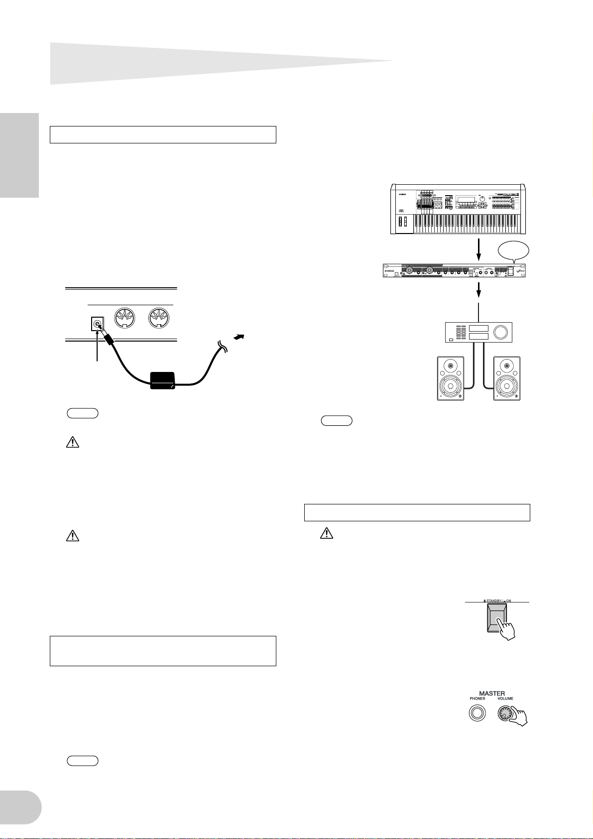
Turning the Power to the i88X and
Connected Devices On and Off
Preparation
Before you connect the power adapter, make
sure that the i88X [STANDBY/ON] switch is set
to STANDBY (Off).
English
A Connect the plug of the power adapter
(PA-5D) to the DC IN terminal on the
rear panel of the i88X.
B Plug in the AC cable to an appropriate
AC outlet.
Rear panel
MIDI
DC IN
DC IN
1
terminal
NOTE
WARNING
• Be sure to use the included adapter. Using an
AC adapter other than the PA-5D may cause
damage to the i88X, and may even pose a
serious electrical shock hazard.
• Connect the adapter to an AC outlet of the
specified voltage.
OUT
Follow this procedure in reverse order
to disconnect the power adapter.
IN
Power adapter
PA-5D
2
AC outlet
1. Turn on the power to the external
devices, such as a sound source or effects
processor connected to the input and
output of the i88X.
2Turn on the
power to
the i88X.
3Turn on the power to
the external audio
equipment connected
to the output of the
i88X. (mixer → amplifier)
NOTE
After you turn on the power to the i88X
again, restart the DAW.
To turn off the power to the devices,
first lower the volume of the audio
equipment, then turn off the power in
the reverse sequence.
Turning on the power to the i88X
POWER
ON!!
12
CAUTION
Even when the [STANDBY/ON] switch is in the
STANDBY position, a small amount of electricity is still flowing to the unit. When you do not
plan to use the i88X for an extended period of
time, be sure to unplug the AC power adapter
from the AC outlet.
Sequence of turning on and off the
power to the connected devices
After you connect the i88X and external
devices (page 13), make sure that the volume
setting on the i88X and external audio equipment is lowered to minimum, then turn on the
power to the devices in the following
sequence.
NOTE
Install mLAN Driver (for Windows)
while the power to the i88X remains off.
(See the separate Installation Guide.)
CAUTION
To protect your speakers, before you turn the
power to the i88X on or off, lower the volume
setting on the i88X and connected audio
equipment.
A Press the i88X [STANDBY/
ON] switch to turn on the
power to the unit.
B Raise the volume of the amplifier to an
appropriate level.
C Set the i88X [GAIN] con-
trols, [MONITOR VOLUME]
control, and [MASTER VOLUME] control to an appropriate level.
Page 13

Connecting External Devices
CAUTION
Before you connect external devices to the i88X, turn off the power to all devices. Also, before you turn on
or off the power to the devices, lower the volume setting on all connected devices to minimum. Otherwise,
electrical shock or damage to the devices may result.
The following diagram illustrates a typical connection example. Refer to this diagram to connect
microphones, musical instruments, a computer, and other external devicves.
Electric guitar/
Bass/Microphone
21
CD recorder/
ADAT-compatible mixer
DIGITAL
STEREO
OUTIN IN
OPTICAL
DIGITAL STEREO
COAXIAL
MIDI
DC IN
OUT
HeadphonesMicrophone
Effects processor
88
876543
876543
INPUT
(BAL)
21
2/ R 1/ L
INSERT I/O
OUTPUT / MASTER
+4dB(BAL)
English
IEEE1394-compatible
computer
Synthesizer/Tone generator
mLAN device
such as 01X
Analog mixer
VOL
Monitor system
VOL
13
Page 14

Wordclocks
NOTE
NOTE
In a system that features multiple digitally-connected devices, all digital devices must be synchronized when digital audio signals are transferred from one device to another.
Even if the devices use matching sampling frequencies, if their audio processing timing is not
synchronized, they might not receive signals correctly, and audible noise, glitches or clicks may
occur. Synchronization is achieved using a wordclock (a clock signal that synchronizes all digital
audio signals in a system).
In a typical digital audio system, one device operates as the wordclock “master” and transmits a
English
wordclock signal. The other devices operate as wordclock “slaves,” synchronizing to the wordclock master.
To connect the i88X to external devices via mLAN, in mLAN Auto Connector or mLAN Graphic
Patchbay, select a device to be the master, then set the other devices as slaves. The i88X can
operate at a sampling frequency of 44.1 kHz, 48 kHz, 88.2 kHz or 96 kHz as either the wordclock
master or slave.
Using the i88X as the wordclock master in an mLAN network
(Using an ADAT-compatible device as the wordclock master in an mLAN network)
1. On the ADAT-compatible device connected to the i88X, specify the ADAT-compatible
device as the wordclock master.
2. Set the [OPTICAL SELECT] switch on the front panel to ADAT DOUBLE or ADAT NORMAL
(page 10).
3. In mLAN Auto Connector or mLAN Graphic Patchbay, assign the i88X as the wordclock
master in the mLAN network.
Using the i88X as the wordclock slave in an mLAN network
In mLAN Auto Connector or mLAN Graphic Patchbay, assign an mLAN device other than the
computer or i88X as the wordclock master.
Use an ADAT-compatible device or digital device (if it is connected to the i88X) to assign
the device as a wordclock slave.
For information on setting the sampling frequency and wordclock, refer to the Installation Guide,
or to the mLAN Graphic Patchbay Online Manual, or the owner’s manual for your ADAT-compatible device.
For information on system requirements and settings for making mLAN connections, refer to
the separate Installation Guide and mLAN Graphic Patchbay Online Manual.
Saving mLAN connection settings to the corresponding mLAN device
When you make mLAN connections on the computer, the connection settings will be automatically saved in the corresponding mLAN devices. Therefore, if you used mLAN Graphic Patchbay
to configure a network that excludes a computer, the next time you use the network, you will be
able to activate the network just by turning on the power to the network’s mLAN devices (without starting the computer).
14
Page 15

About connections with external devices when using the i88X with a computer
When using audio devices, musical instruments and computers at the same time, there is bound to
be some noise in the system, the amount of which depends on the connections. Knowing how to
minimize noise is extremely important when designing and setting up a studio.
As advanced as the i88X is, it too is susceptible to noise. Various types of noise may be generated
and recorded to your audio sequencer, depending on the power sources/grounding scheme and
how the various devices are connected.
There is no ideal way to completely eliminate such noise. However, one can decrease noise by isolating the cause and applying a suitable remedy. Below are a couple of examples that may apply.
• High-pitched buzzing or whirring operation noise in the computer
This is caused by operation noise of the computer leaking to other devices through the mLAN
cable or audio cable, and may be caused by improper grounding of the power source.
• Low humming noise
Noise of this type is generally due to improper grounding of the power source.
English
NOTE
The noise may differ depending on the circumstances (specifications of each device and locations of use).
If problems like these happen, try the following measures to minimize the noise.
NOTE
If the noise disappears when turning down the volume of the i88X and/or if the noise persists
even when disconnecting the mLAN cable or turning off the computer, other reasons for the
noise are likely. Refer to the Troubleshooting section in the Owner’s Manual.
1. Use balanced cable connections when connecting analog audio.
By using proper balanced connections, you can minimize the noise.
NOTE
This may have no effect depending on the specifications of the connected device.
■ Recommended Cables
i88X Inputs
Outputs of connected devices / i88X inputs (balanced) i88X inputs
Balanced
(mixer, mic preamp, etc.)
Unbalanced
(MIDI tone generator, etc.)
TRS 1/4" phone / XLR ↔ TRS phone / XLR balanced cable Ch. 1-2
TRS 1/4" phone / XLR ↔ TRS phone balanced cable Ch. 3-8
Unbalanced 1/4" phone ↔ TRS phone / XLR balanced cable Ch. 1-2
Unbalanced 1/4" phone ↔ TRS phone balanced cable Ch. 3-8
i88X Outputs
i88X outputs (OUTPUT1-OUTPUT8) / Inputs of connected devices (balanced)
Balanced
Balanced TRS 1/4" phone ↔ TRS phone / XLR balanced cable —
—
2. Insert a conventional direct box (passive, with transformer and ground lift switch) for connecting the audio (analog) cable.
NOTE
Example:
You may want to use several direct boxes when connecting multiple devices.
OUTPUT 1/2 of i88X – [direct box] – powered speaker
Synthesizer – [direct box] – i88X
3. Changing the power source for each device.
WARNING
Attempting this remedy is extremely dangerous and may result in electric shock. It should be done only by
qualified, experienced personnel. Contact your nearest Yamaha representative or an authorized distributor (see the last page of the Owner’s Manual).
15
Page 16

Connecting Musical Instruments and
NOTE
NOTE
Microphones and Adjusting the Input Level
Signals input at INPUT 1-8 jacks are routed to mLAN output channels 1-8 respectively. If you have
selected any pair from channels 1/2 through 7/8 for monitor output, you can monitor the corresponding input signals from MASTER L & R and MASTER PHONES (page 17).
This section describes connecting musical instruments and microphones to the INPUT 1-8 jacks and
adjusting the level of input signals.
English
ANALOG
INPUTS
1, 2, 3/4,
5/6, 7/8
GAIN
INSERT I/O
(Only Ch 1 & 2)
mLAN
OUTPUTS
MONITOR
MONITOR
SELECT
mLAN INPUTS
3-8
(from DAW output)(to DAW output)
mLAN INPUTS
1, 2
(from DAW master output)
VOLUME
MASTER
VOLUME
ANALOG
OUTPUTS
3-8
PHONES
ANALOG
OUTPUTS
1/L, 2/R
1. Turn the [MASTER VOLUME] control and the [MONITOR VOLUME] control all the way to
the minimum (rotate the controls counter-clockwise until the knob will not turn further).
To connect devices to INPUT 1 & 2, set the [(HI-Z)/LINE/MIC] switch to a setting that is appropriate for the connected devices (page 8).
You can insert an effects processor via the INSERT I/O jacks into analog input channels 1 and
2 (INPUT 1 & 2).
2. Connect the musical instruments and microphones to the INPUT 1-8 jacks.
3. Adjust the [GAIN] control for the INPUT jacks to which you connected the musical instruments and microphones.
4. Adjust the [MASTER VOLUME] control and the [MONITOR VOLUME] control.
INPUT 1 & 2 jacks:
In order to record at the optimal level, adjust the [GAIN] controls so that the [PEAK] indicator for
each input flickers briefly when you play at your loudest level.
INPUT 3 - 8 jacks
Observe the input level meters of your DAW or audio sequencer while adjusting the [GAIN] controls
to raise the level to a point just before the signal starts clipping.
16
Page 17

Direct Monitoring
Through the MASTER L & R jacks and the MASTER PHONES jack, you can directly monitor signals
input at INPUT 1-8 jacks or COAXIAL or OPTICAL DIGITAL STEREO INPUT jacks.
When an audio input signal, such as a guitar or vocal signal, is output through the computer,
latency (delay) may occur. However, this Direct Monitoring function enables you to monitor a signal before it is output to the connected computer, and thus avoids latency in the monitoring signal.
NOTE
If you wish to record to the DAW your vocal or musical instrument performance accompanying
the DAW’s background tracks, while listening to the sound through the i88X, turn off the monitoring function on the DAW. Otherwise, you will have to listen to a delayed sound (from the
DAW) and to a non-delayed sound (monitoring sound from the i88X) at the same time, resulting in a garbled sound.
mLAN INPUTS
1, 2
ANALOG
INPUTS
DIGITAL STEREO
INPUTS
1/2
3/4
5/6
7/8
MONITOR
SELECT
MONITOR
VOLUME
MASTER
VOLUME
PHONES
ANALOG
OUTPUTS
1/L, 2/R
1. Follow Steps 1 and 2 in “Connecting Musical Instruments and Microphones and Adjusting
the Input Level” on page 16 to connect the musical instruments and microphones to the
INPUT 1-8 jacks or COAXIAL or OPTICAL DIGITAL SETEREO INPUT jacks.
2. Press the [SELECT] button on the front panel (page 9) repeatedly to select a an input channel for direct monitoring through the MASTER OUT L & R jacks on the rear panel.
Press the switch briefly (less than one second) repeatedly to select monitoring channels in the
following sequence:
Off → CH1/2 → CH3/4 → CH5/6 → CH7/8 → DIGITAL STEREO -> Off
The MONITOR indicator (page 9) for the selected channels lights up red.
English
3. Adjust the [GAIN] controls for the INPUT channels (to which the musical instruments and
microphones are connected) and the [MASTER VOLUME] control.
4. Adjust the [MONITOR VOLUME] control.
Monitoring signals are output from the MASTER L & R jacks and the MASTER PHONES jack.
The [MONITOR VOLUME] control enables you to adjust the volume of the monitoring signals
without changing the recording level (input gain).
17
Page 18

System Examples
1. Connecting the i88X to the computer
Connect the IEEE1394 connector on an IEEE1394-compatible computer to the mLAN connector
on the i88X using an IEEE1394 cable. In mLAN Auto Connector or mLAN Graphic Patchbay
(page 20), route the audio and MIDI signals between the computer and the i88X and set up the
wordclock.
This system enables you to transfer multiple audio streams from the connected musical instru-
English
ments and mixer to the computer simultaneously, and transfer multiple audio outputs from the
computer to the mixer simultaneously.
Guitar/
Bass
Connecting musical instruments
and a microphone Connecting a mixing console
IEEE1394-compatible computer IEEE1394-compatible computer
IEEE1394 cable
i88X i88X
Microphone
MTR
IEEE1394 cable
PAD
26dB126dB226dB326dB426dB526dB626dB726dB826dB926dB1026dB1126dB
–60–16
–60–16
–60–16
+10 –34
+10 –34
+10 –34
GAIN
GAIN
GAIN
UTILITY MIDI SETUP VIEW
PAN/
DYNAMICS EQ/ATT Ø/DELAY
ROUTING
FADER MODE
EFFECT 1 EFFECT 2 OPTION I/O REMOTE
AUX 1
AUX 2 AUX 3 AUX 4
HOME
4
3
2
1
17
SEL
SEL
SEL
SEL
SOLO
SOLO
SOLO
SOLO
ON
ON
ON
ON
6
6
6
6
0
0
0
0
5
5
5
5
10
10
10
10
20
20
20
20
40
40
40
40
60
60
60
60
∞
∞
∞
∞
4
3
2
1
17 18 19 20 21 22 23 24
OFF
OFF
ON
PHANTOM +48V
–60–16
+10 –34
+10 –34
GAIN
GAIN
FUNCTION
5
SEL
SOLO
ON
6
0
5
10
10
20
20
40
40
60
60
∞
∞
5
ON
PHANTOM +48V
INPUT (BAL)
–60–16
–60–16
+10 –34
+10 –34
GAIN
GAIN
MEMORY
1 RETURN 2
8
7
6
232221201918
24
SEL
SEL
SEL
SOLO
SOLO
SOLO
ON
ON
ON
6
6
6
0
0
0
5
5
5
10
10
20
20
40
40
60
60
∞
∞
8
7
6
–10dBV (UNBAL)
131415
L
R
16
IN
OUT
2TR
PHONES
MONITOR
15/16
2TR IN
2TR IN
–20+10 100 100
–20+10
–60–16
–60–16
–60–16
–60–16
–60–16
–60–16
LEVEL LEVELGAIN
GAIN
+10 –34
+10 –34
+10 –34
+10 –34
+10 –34
GAIN
GAIN
GAIN
GAIN
GAIN
MONITOR
12
OUT
13/14 15/16 PHONES
DIGITAL MIXING CONSOLE
L STEREO R
EQ
HIGH
CLIP
PAN
–3
–6
PAN
HI-MID
–9
–12
F
F
–15
–18
G
–24
LO-MID
–30
–36
–42
–48
G
LOW
SELECTED CHANNEL
STEREO
15/16
13/14
12
11
10
9
1 RETURN 2
MASTER
SELSEL
SEL
SEL
SEL
SEL
SEL
SEL
SEL
SOLO
SOLO
ON
6
6
0
0
5
5
10
10
20
20
40
40
60
60
∞
∞
9
SOLO
SOLO SOLO
SOLO
SOLO
SOLO
SOLO
ON
ON
ON
ON
ON
ON
ON ON
MEMORY
–1/DEC
+1/INC
PARAMETER
0
6
6
6
6
–5
0
0
0
0
–10
–15
5
5
5
5
–20
CURSOR
10
10
10
10
–30
20
20
20
20
–40
–50
40
40
40
40
–70
60
60
60
60
∞
∞
∞
∞
– ∞
ENTER
15/16
13/14
12
11
10
STEREO
MASTER
18
Synthesizer
mLAN MIDI
IN/OUT
mLAN IN/OUT
MIDI
IN/OUT
Computer
mLAN IN/OUT
1-8ch
INPUT/
OUTPUT
1-8
mLAN IN/OUT
9-10ch
DIGITAL
STEREO
IN/OUT
mLAN
IN/OUT
ADAT
IN/OUT
Mixer
11-18ch
(44.1kHz/48kHz)
11-14ch
(88.2kHz/96kHz)
MONITOR
SELECT
MASTER OUT
L/R
Page 19

2. Using multiple mLAN devices
Connect the mLAN (IEEE1394) connector on the IEEE1394-compatible computer and the mLAN
(IEEE1394) connector on the 01X Digital Mixing Studio and on the i88X using IEEE1394 cables.
In mLAN Graphic Patchbay (refer to the mLAN Graphic Patchbay Online Manual), route the
audio and MIDI signals between the computer and the i88X and set up the wordclock.
This system enables you to make best use of the 01X Digital Mixing function (up to 28-channel
digital mixing). Using eight A/D inputs on the 01X and eight A/D inputs on the i88X enables you
to transfer 16-channel analog audio data to the 01X. Eight D/A outputs on the i88X are available, as well as MONITOR OUT (stereo) and STEREO/AUX OUT (stereo) on the 01X. These analog interface and the i88X COAXIAL and OPTICAL DIGITAL STEREO jacks expand analog and
digital input and output on the 01X.
English
NOTE
Sampler
The number of available input and output channels may vary depending on the specific mLAN
devices connected. For the best performance, it is recommended that you connect up to four
mLAN devices (including a computer) in a network. If the network contains an mLAN device
that is only compatible with a low transfer rate (200 Mbps (S200)), the number of devices and
channels available for connection will be reduced.
IEEE1394-compatible
computer
ADAT recorder
ADAT
IEEE1394 cable
01X
i88X
01X
Microphones
mLAN OUT
MIXER
INPUT
1-8
1-16ch
mLAN IN
1-18ch
Guitar
mLAN
IN/OUT
Bass
Computer
mLAN
IN/OUT
Synthesizer
mLAN
IN/OUT
1-8ch
INPUT/
OUTPUT
1-8
mLAN
IN/OUT
9-10ch
DIGITAL
STEREO
IN/OUT
MTR
i88X
mLAN IN/OUT
11-18ch
(44.1kHz/48kHz)
11-14ch
(88.2kHz/96kHz)
ADAT
IN/OUT
19
Page 20

Making mLAN Connections
NOTE
In an mLAN system, you can easily configure and maintain the system, connect or disconnect the
mLAN connectors on the computer and each mLAN device (virtual audio /MIDI input and output
connectors), and make various mLAN connection settings (such as synchronization) by using the
mLAN Graphic Patchbay and mLAN Auto Connector software applications. There is no need to repatch audio and MIDI cables to accommodate various music production environments.
English
mLAN Auto Connector
This software application enables you to connect a computer to a single mLAN device.
It enables you to easily select wordclock and audio input and output channels.
For information on installing and using the software, refer to the separate Installation Guide.
You can also use mLAN Graphic Patchbay to connect a computer to a single mLAN device.
Windows Macintosh
mLAN Graphic Patchbay
This graphic software application enables you to manage mLAN connection settings for the connected computer and multiple mLAN devices. You can immediately grasp connections in their
entirety by viewing displayed mLAN system configuration graphics. You can also intuitively modify wordclock settings and audio and MIDI signal routing, much as if you were connecting physical cables.
For information on installing and using the software, refer to the separate Installation Guide and
the mLAN Graphic Patchbay Online Manual.
Windows Macintosh
20
Page 21

LED Indicators
Indicators Status Meaning
ACTIVE Steady blue The i88X is operating normally as an mLAN device.
Off An error has occurred during mLAN operation.
MASTER CLOCK INT Steady green The i88X is using the INTERNAL sampling frequency of
44.1 kHz.
ADAT Steady green The i88X is locking to the wordclock master (ADAT).
Flashing green The i88X is not locking to the wordclock master
(ADAT).
mLAN Steady green The i88X is locking to the wordclock master (ADAT).
Flashing green The i88X is not locking to the wordclock master
(ADAT).
English
MONITOR
/Sampling Rate
PEAK Steady red The analog input signal has reached the peak level.
NOTE
1/2 (44k) Steady red CH 1&2 are selected for monitoring output.
Flashing red The i88X is operating with a sampling frequency of
44.1 kHz.
3/4 (48k) Steady red CH 3&4 are selected for monitoring output.
Flashing red The i88X is operating with a sampling frequency of
48 kHz.
5/6 (88k) Steady red CH 5&6 are selected for monitoring output.
Flashing red The i88X is operating with a sampling frequency of
88 kHz.
7/8 (96k) Steady red CH 7&8 are selected for monitoring output.
Flashing red The i88X is operating with a sampling frequency of
96 kHz.
DIGITAL Steady red DIGITAL is selected for monitoring output.
When you press and hold down the [SELECT] switch for one second or longer, the MONITOR/Sampling Rate indicator for the current operating sampling frequency (44k, 48k, 88k, or
96k) flashes red.
21
Page 22

Troubleshooting
If you encounter a problem...
If you hear no sound or a strange sound, first check the items described below and take appropriate
action. If the problem persists, consult your Yamaha dealer.
■ No sound or very low volume level
• Are speakers or headphones connected correctly?
English
• Is your amp and other external devices turned on?
• Is the signal from the external device being input?
• Are all the level settings (of any tone generators, playback devices and the application itself) appropriate?
• The connection cable from the external device may be broken.
• Is the wordclock setting correct for both the i88X and the external device(s)?
............Refer to “Connecting a Computer to an mLAN device via mLAN” in the Installation
Guide, and “Wordclock Settings” in the mLAN Graphic Patchbay Online Manual.
• (For Windows) Is mLAN (mLAN Driver) set to “ON”? From the task bar, right click on the mLAN Manager
(mLAN icon).
• Are the other settings of mLAN appropriate? ........Refer to “Unable to communicate via mLAN (page 23).”
• If there are more than four devices (including a computer) on the network, the limit of the IEEE1394 BUS
bandwidth may be exceeded.
• The limit of the IEEE1394 BUS bandwidth may have been exceeded. Check the current bandwidth using
mLAN Graphic Patchbay, and disconnect some devices if necessary.
.......................................... Refer to “Menu Bar” in the mLAN Graphic Patchbay Online Manual.
• If there is an mLAN device that supports only S200 on the mLAN network, the IEEE1394 BUS bandwidth
may be reduced and its limit exceeded. Reduce the number of mLAN devices connected to the network, or
disconnect some devices as necessary.
.......................................... Refer to “Menu Bar” in the mLAN Graphic Patchbay Online Manual.
■ Distorted sound
• Is the [GAIN] control set correctly? ...................................................................................Refer to page 16.
• The connection cable from the external device may be broken.
• Is the wordclock setting correct for both the i88X and the external device(s)?
............Refer to “Connecting a Computer to an mLAN device via mLAN” in the Installation
Guide and “Wordclock Settings” in the mLAN Graphic Patchbay Online Manual.
• Make sure audio data was recorded at an appropriate level.
■ Noise is audible
• Is the latency setting of the mLAN Driver appropriate?
...........Refer to “mLAN Driver Setup” and “ASIO mLAN Control Panel” in the Installation Guide.
• (For Windows) Setting Hyper Threading to off in the BIOS settings may solve the problem.
• Is the wordclock setting correct for both the i88X and the external device(s)?
............Refer to “Connecting a Computer to an mLAN device via mLAN” in the Installation
Guide and “Wordclock Settings” in the mLAN Graphic Patchbay Online Manual.
• If the speed of your computer's hard disk is slow, problems may occur during recording and playback.
• If you connect/disconnect the LAN, USB or the cables to the mini jacks terminals on the Macintosh you are
using when using mLAN, some noise may be caused and/or data may be cut off. Make sure that you do
not insert or unplug any connections when using mLAN.
• Is the number of audio channels appropriate? The amount of audio channels that can be used simulta-
neously differs depending on the computer capacity and speed.
............Refer to “Connecting a Computer to an mLAN device via mLAN” in the Installation
Guide and “mLAN Connection Settings” in the mLAN Graphic Patchbay Online Manual.
• Is the sampling rate (wordclock) appropriate? A high sampling rate can be the cause of the noise depend-
ing on the computer capacity and speed.
............Refer to “Connecting a Computer to an mLAN device via mLAN” in the Installation
Guide and “mLAN Connection Settings” in the mLAN Graphic Patchbay Online Manual.
• Make sure that the appropriate number of devices is connected to the computer. Connection of too many
devices may cause noise, depending on the capacity of the computer.
• Are there any noise-producing devices (such as those containing power inverters, etc.) near the cables?
Move all cables away from any possible noise sources.
• Make sure the mLAN cable is not damaged. Cables that do not satisfy IEEE1394 standards may cause noise.
22
Page 23

• Do not run applications, such as anti-virus software, in the background. While using the mLAN system,
turn off all applications that run in background. If these applications remain on, driver operation may
become unstable and cause noise. If you do not plan to use the mLAN system, you can turn these applications on. (You can turn the mLAN driver on and off using mLAN Manager.)
■ Insufficient tracks for recording or playback
• Is the number of channels for mLAN audio receiving/sending (set on the mLAN Auto Connector and mLAN
Graphic Patchbay) appropriate?
............Refer to “Connecting a Computer to an mLAN device via mLAN” in the Installation
Guide and “mLAN Connection Settings” in the mLAN Graphic Patchbay Online Manual.
■ Unable to transfer MIDI data or Program Changes
• Are the MIDI cables connected correctly?
•A MIDI cable may be broken.
• Is the power turned on for the transmitting and receiving devices?
• Make sure the transmission and reception channels match.
■ Incorrect pitch
• Is the i88X operating on the same sampling frequency as the synchronized external device?
............Refer to “Connecting a Computer to an mLAN device via mLAN” in the Installation
Guide and “Wordclock Settings” in the mLAN Graphic Patchbay Online Manual.
• Is the master device operating in a stable way?
■ Unable to communicate via mLAN
• Has the driver been installed? ...................................................................... Refer to the Installation Guide.
• Is the mLAN cable properly connected? Check the connection; disconnect the mLAN cable once, then
insert it again.
• (For Windows) Is mLAN set to “ON”? From the task bar, right click on the mLAN Manager icon.
...................................................Refer to “Confirming the installation” in the Installation Guide.
• (For Windows) When adding a new IEEE 1394 card, right click on the mLAN Manager icon in the task bar
and select “ON.”.
...................................................Refer to “Confirming the installation” in the Installation Guide.
• Is the ACTIVE lamp on the rear panel of the i88X lit (in blue)? If it is not lit, check the followings:
- In mLAN Driver Setup, is the Status indicator blue? If not, restart the i88X and re-enable connection by
using mLAN Auto Connector or mLAN Graphic Patchbay.
............Refer to “Changing settings after installation” in the Installation Guide and the mLAN
Graphic Patchbay Online Manual.
• Has connection been enabled with mLAN Auto Connector and/or Graphic Patchbay? Re-enable connection if necessary.
............Refer to “Connecting a Computer to an mLAN device via mLAN” in the Installation
Guide and “mLAN Connection Settings” in the mLAN Graphic Patchbay Online Manual.
• Have you changed the device? Even if the model is the same, if the actual device is different, it is necessary
to re-enable connection by using Auto Connector and/or Graphic Patchbay.
............Refer to “Connecting a Computer to an mLAN device via mLAN” in the Installation
Guide and “mLAN Connection Settings” in the mLAN Graphic Patchbay Online Manual.
• Is there a loop connection? Check the cabling and make sure none of the devices are connected in a loop.
English
Computer
• There may be a limit on the IEEE 1394 interface of your computer as to the number of ports that can be
used simultaneously. Check how many ports can be used simultaneously.
•Turn off all devices on the mLAN network (except the computer) and re-connect each device one-by-one
until the device causing the problem is found.
• (For Windows) (When removing the mLAN bus from the [Safely Remove Hardware] setting of the task bar.)
Restart the computer when using mLAN again.
•With Macintosh notebook computers such as the iBook and PowerBook, always first connect the i88X and
mLAN cable then turn on the power of the i88X, before starting up the computer.
i88X
Computer
i88X
: IEEE 1394-equipped device
23
Page 24

■ An application, such as a DAW, fails to recognize the mLAN driver (MIDI/audio).
• (For Windows) Make sure mLAN has not been turned off. On the task bar, right-click mLAN Manager ( ),
then select ON. ... Refer to “Confirming the installation” in the Installation Guide and “mLAN Connection
Settings” in the mLAN Graphic Patchbay Online Manual.
• Make sure the i88X is connected to the mLAN cable and is powered on. Start mLAN Auto Connector or
mLAN Graphic Patchbay, then re-connect the device.
............Refer to “Confirming the installation” in the Installation Guide and “mLAN Connection
Settings” in the mLAN Graphic Patchbay Online Manual.
• (For Macintosh) To use an iBook or PowerBook in the system, connect the i88X to the Macintosh using an
mLAN cable, turn on the power to the i88X, then start the Macintosh.
English
• Make sure the mLAN settings are correct. ........ Refer to “Unable to communicate via mLAN” on page 23.”
■ The computer processing speed is too slow.
■ The computer’s CPU meter indicates a heavy processing load.
■ Playback response is delayed.
• Make sure your computer satisfies the system requirements.
........................................................... Refer to “System Requirements” in the Installation Guide.
• (For Windows) If you do not use the mLAN system, on the task bar right-click mLAN Manager ( ), then
select OFF (mLAN quits). ............................Refer to “Confirming the installation” in the Installation Guide.
•Try reducing the number of audio channels in mLAN Auto Connector or Graphic Patchbay.
............Refer to “Connecting the Computer and mLAN devices via mLAN” in the Installation
Guide and “mLAN Connection Settings” in the mLAN Graphic Patchbay Online Manual.
•Try increasing the latency value.
................................Refer to “Changing the Settings after Installation” in the Installation Guide.
• (For Macintosh) If a dual-CPU model awakes from Sleep or Suspend mode, processing speed may be
slowed. In this event, restart the computer.
• (For Windows) Refer to “Hints when using audio data (Windows).” ............ Refer to the Installation Guide.
• (For Windows) The condition may improve if you set “Hyper Threading” to “Disable.”
• Using mLAN Graphic Patchbay, try reducing the number of devices connected to the computer.
............Refer to “mLAN Connection Settings” in the mLAN Graphic Patchbay Online Manual.
• (For Macintosh) Turn off virtual memory.
• (For Macintosh) Disable Apple Talk.
24
■ Inconsistency in wordclock, or unable to exit from Auto Connector
• (For Windows) Mobile computers with Intel CPU
SpeedStep ™ technology is applied for some CPU’s (CPU for notebook PC). Please disable the SpeedStep
™ technology when mLAN is employed. SpeedStep™ technology changes CPU clock dynamically depending on the loading on the CPU to save the power consumption.
- How to disable the SpeedStep™ technology;
In almost all of the PC’s, BIOS has a function to select enabling or disabling the SpeedStep ™ technology. Please refer to the PC’s operating manual, or make inquiry to the PC manufacturer.
■ Unable to close the application or operating system
■ Unable to change the mLAN settings
■ Unable to uninstall mLAN Applications for Yamaha or mLAN Tools 2.0
• (For Windows) Is the mLAN (WDM) driver selected as the default audio device for the system?
- Select [Start | Control Panel | Sounds and Audio Devices | Voice].
Make sure that something other than “mLAN Audio 01” is selected for the [Voice playback] and [Voice
recording] settings.
- Select [Start | Control Panel | Sounds and Audio Devices | Audio].
Make sure that something other than “mLAN Audio 01” is selected for the [Sound playback] and [Sound
recording] settings.
- In “MIDI music playback,” select any option other than the range of options from “mLAN
MIDI Out” through “mLAN MIDI Out (8).”
• (For Windows) Select [Start | Control Panel | Sounds and Audio Devices | Sounds]. And select “No sounds”
in the [Sound scheme], then execute again.
• (For Windows) If you cannot quit mLAN (by selecting “OFF” after right clicking the mLAN icon in the task
bar), end the processes listed below manually. ([Ctrl] + [Alt] + [Delete] → [Processes] → select process →
[End process]) When finished, start mLAN Manager to change the mLAN settings again.
- mLANVDevice.exe
- mLANTFamily.exe
- mLANSoftPH.exe
- mLANManager.exe
Page 25

To change mLAN settings, select [Start | (All) Programs | Start Up], then start mLAN Manager.
- (When a message such as “file cannot be found” appears when uninstalling:)
Try executing the installation once more, then uninstall again.
■ (Windows) mLAN Manager (the mLAN icon in the task bar) has disappeared.
• Select [Start | (All) Programs | Start Up (or mLAN Tools)], then select mLAN Manager.
Specifications
■ General Specifications
Sampling Frequency Internal, External
Frequency
Response
Total Harmonic Distortion Less than 0.01%
Dynamic Range 110dB Line Input to Master Output L/R (1/2ch) or 3–8 ch
Noise level –100dBu (Output Vol: Min.), –90dBu (Output Vol: Max.)
Crosstalk 75dB 1kHz
AD converter
DA converter
Fs 44.1kHz, 48kHz 20Hz to 20kHz 0+1/–3dB, Input to Master Output L/R (Fs 48kHz, MIC/LINE)
Fs 88.2kHz, 96kHz 20Hz to 40kHz 0+1/–3dB, Input to Master Output L/R (Fs 96kHz, MIC/LINE)
24bit Linear, 128times over sampling (Fs 44.1,48kHz) / 64time over sampling
(Fs 88.2,96kHz)
24bit Linear, 128times over sampling (Fs 44.1,48kHz) / 64time over sampling
(Fs 88.2,96kHz)
Normal Rate Fs 44.1kHz(–10%) to 48kHz(+6%)
Double Rate Fs 88.2kHz(–10%) to 96kHz(+6%)
1kHz, Line Input to Master Output L/R (Input Gain = Min,
Output Vol = Max)
English
*1
Interface Functions
Compatible mLAN transfer rate S400 (400Mbps) / S200 (200Mbps)
18ch Input / 18ch Output (Fs 44.1kHz, 48kHz)
mLAN Audio I/F
MIDI I/F 1 Input port / 1 Output port
Type: Input (Analog) 8ch, Digital Input 2ch, ADAT Input 8ch
14ch Input / 14ch Output (Fs 88.2kHz, 96kHz)
Type: Input (Analog) 8ch, Digital Input 2ch, ADAT Input 4ch
■ Input/Output Specifications
Analog Input Connector
INPUT 1,2
INPUT 3-8
INSERT IN 1-2
Analog Output Connector
OUTPUT 1-8
(MASTER OUT L/R)
INSERT OUT 1-2
PHONES TRS Phone, UnBalanced — 100mW+100mW 33Ω (33Ω)
XLR/TRS Phone Combo
Balanced, +48V ±3V Phantom,
Mic/Line/Hi-Z
TRS Phone
TRS Phone
*3
, Balanced, Line
*4
, UnBalanced
TRS Phone, Balanced
*4
TRS Phone
, UnBalanced
*2
,
*3
–60dBu to –16dBu (Mic) –2dBu
–34dBu to +10dBu (Line) +24dBu
–56dBu to –12dBu (Hi-Z) +2dBu 500kΩ
Nominal Max. before clip Input Impedance
–20dBu to +10dBu +24dBu 10kΩ
–2dBu +12dBu 10kΩ
Nominal Max. before clip
+4dBu +18dBu 2kΩ (10kΩ)
–2dBu +12dBu 600Ω (10kΩ)
Input level
3kΩ
Output level
Actual Load Impedance
(Rated Load Impedance)
25
Page 26

Digital Input/
Output
ADAT/DIGITAL
OPTICAL IN, OUT
DIGITAL STEREO
IN, OUT
MIDI IN, OUT A/B DIN 5pin MIDI —
English
mLAN 1/2 IEEE1394 6pin mLAN — Compatible with S400 and S200
*1: Signal input from ADAT-compatible device: Normal Rate Fs 44.1KHz(–6%) to 48KHz(+6%)
*2: Always balanced, regardless of whether a XLR-3-31 or TRS phone is used. (1=GND, 2=HOT, 3=COLD/Tip=HOT, Ring=COLD,
Sleeve=GND)
*3: Balanced Phone (Tip=HOT, Ring=COLD, Sleeve=GND)
*4: INSERT IN & OUT feature unbalanced phone jacks. (Tip = OUTPUT, Ring=INPUT, Sleeve=GND)
*5: ALESIS proprietary multi-channel optical digital interface format
In these specifications, when dBu represents a specific voltage, 0 dBu is referenced to 0.775 Vrms.
Connector Format
*5
ADAT
OPTICAL
RCA PIN IEC-60958 Consumer use 0.5Vpp/75Ω
IEC-60958 Consumer use
(DIGITAL)
Double Rate Fs 88.2KHz(–6%) to 96KHz(+6%)
Recommended
output level
—
—
Other details
Supports DOUBLE
(up to 96 kHz).
The IN jack features an internal
sampling rate converter.
■ Control
Input Gain Gain Knob 1, 2, 3, 4, 5/6, 7/8
Phantom Switch
Gain Select Switch (PAD Switch) Input Ch 1 : Mic/Line/Hi-Z, Input Ch 2 : Mic/Line
Peak LED Input 1, 2 channel
Monitor Select Switch (Fs Indicator)
Monitor LED (Fs Indicator)
Monitor Volume Direct Monitoring Volume for selected channel by monitor switch
Master Volume Output Level of Master Output L/R and Phones
Optical Select Switch Digital / ADAT Normal / ADAT Double
Master Clock LED mLAN / ADAT / Internal (fixed at 44.1kHz)
mLAN Active LED For Information of mLAN’s situation
Power Switch Stand by/On switch
*6: Phantom power (+48 V) is not supplied when the TRS phone is used. If the [HI-Z/LINE/MIC] switch is set to HI-Z, phantom
power is not supplied to INPUT jack 1.
Phantom (+48V) On/Off for Input1,2 channel with LED
Direct Monitoring Channel Selector : 1/2, 3/4, 5/6, 7/8, Digital In / Fs Indicator
(holding down a while)
Direct Monitoring Channel Selector : 1/2, 3/4, 5/6, 7/8, Digital In / Fs Indicator :
44.1, 48, 88.2, 96kHz
*6
26
■ Others
Supplied Accessories
Power Consumption 16W
Dimensions 480(W) x 372.7(D) x 44(H)
Weight 3.9kg
Power Adaptor (PA-5D), Owner’s Manual set, CD-ROM x 2, mLAN (IEEE1394)
cable
* Specifications and descriptions in this owner’s manual are for information purposes only. Yamaha
Corp. reserves the right to change or modify products or specifications at any time without prior
notice. Since specifications, equipmentr or options may not be the same in every locale, please
check with your Yamaha dealer.
Page 27

VORSICHTSMASSNAHMEN
Gefahr durch Wasser
Brandschutz
Falls Sie etwas ungewöhnliches am Gerät bemerken
BITTE SORGFÄLTIG DURCHLESEN, EHE SIE WEITERMACHEN
* Heben Sie diese Anleitung sorgfältig auf, damit Sie später einmal nachschlagen können.
WARNUNG
Befolgen Sie unbedingt die nachfolgend beschriebenen grundlegenden Vorsichtsmaßnahmen, um die Gefahr einer
schwer wiegenden Verletzung oder sogar tödlicher Unfälle, von elektrischen Schlägen, Kurzschlüssen,
Beschädigungen, Feuer oder sonstigen Gefahren zu vermeiden. Zu diesen Vorsichtsmaßnahmen gehören die
folgenden Punkte, die jedoch keine abschließende Aufzählung darstellen:
Stromversorgung/Netzadapter
• Verwenden Sie ausschließlich die für das Instrument vorgeschriebene richtige
Netzspannung. Die erforderliche Spannung finden Sie auf dem Typenschild
des Instruments.
• Ausschließlich den vorgeschriebenen Adapter (PA-5D oder einen
gleichwertigen, von Yamaha empfohlenen) verwenden. Wenn Sie den falschen
Adapter einsetzen, kann dies zu Schäden am Instrument oder zu Überhitzung
führen.
• Prüfen Sie den Netzstecker in regelmäßigen Abständen und entfernen Sie
eventuell vorhandenen Staub oder Schmutz, der sich angesammelt haben
kann.
• Verlegen Sie das Netzkabel niemals in der Nähe von Wärmequellen, etwa
Heizkörpern oder Heizstrahlern, biegen Sie es nicht übermäßig und
beschädigen Sie es nicht auf sonstige Weise, stellen Sie keine schweren
Gegenstände darauf und verlegen Sie es nicht an einer Stelle, wo jemand
darauftreten, darüber stolpern oder etwas darüber rollen könnte.
Öffnen verboten!
• Verlegen Sie das Kabel des Adapters niemals in der Nähe von Wärmequellen,
etwa Heizkörpern oder Heizstrahlern, biegen Sie es nicht übermäßig und
beschädigen Sie es nicht auf sonstige Weise, stellen Sie keine schweren
Gegenstände darauf und verlegen Sie es nicht an einer Stelle, wo jemand
darauftreten, darüber stolpern oder etwas darüber rollen könnte.
• Achten Sie darauf, dass das Instrument nicht durch Regen nass wird,
verwenden Sie es nicht in der Nähe von Wasser oder unter feuchten oder
nassen Umgebungsbedingungen und stellen Sie auch keine Behälter mit
Flüssigkeiten darauf, die herausschwappen und in Öffnungen hineinfließen
könnte.
• Schließen Sie den Netzstecker niemals mit nassen Händen an oder ziehen Sie
ihn heraus.
• Stellen Sie keine offenen Flammen, wie z.B. Kerzen, auf dem Gerät ab. Eine
offene Flamme könnte umstürzen und einen Brand verursachen.
• Wenn das Kabel des Adapters ausgefranst oder beschädigt ist, wenn es
während der Verwendung des Instruments zu einem plötzlichen Tonausfall
kommt, oder wenn es einen ungewöhnlichen Geruch oder Rauch erzeugen
sollte, schalten Sie sofort den Einschalter aus, ziehen Sie den Adapterstecker
aus der Netzsteckdose und lassen Sie das Instrument von einem qualifizierten
Yamaha-Kundendienstfachmann prüfen.
Deutsch
VORSICHT
Befolgen Sie unbedingt die nachfolgend beschriebenen grundlegenden Vorsichtsmaßnahmen, um die Gefahr von
Verletzungen bei Ihnen oder Dritten, sowie Beschädigungen des Instruments oder anderer Gegenstände zu
vermeiden. Zu diesen Vorsichtsmaßnahmen gehören die folgenden Punkte, die jedoch keine abschließende
Aufzählung darstellen:
Nähe einer Heizung oder Lagerung tagsüber in einem geschlossenen
Stromversorgung/Netzadapter
• Wenn Sie den Netzstecker aus dem Instrument oder der Netzsteckdose
abziehen, ziehen Sie stets am Stecker selbst und niemals am Kabel. Wenn Sie
am Kabel ziehen, kann dieses beschädigt werden.
• Ziehen Sie während eines Gewitters oder wenn Sie das Instrument längere Zeit
nicht benutzen den Netzadapter aus der Netzsteckdose.
• Schließen Sie das Instrument niemals mit einem Mehrfachsteckverbinder an
eine Steckdose an. Hierdurch kann sich die Tonqualität verschlechtern oder
sich die Netzsteckdose überhitzen.
Aufstellort
• Setzen Sie das Instrument niemals übermäßigem Staub, Vibrationen oder
extremer Kälte oder Hitze aus (etwa durch direkte Sonneneinstrahlung, die
(3)-7 1/2
Fahrzeug), um die Möglichkeit auszuschalten, dass sich das Bedienfeld
verzieht oder Bauteile im Innern beschädigt werden.
• Betreiben Sie das Instrument nicht in der Nähe von Fernsehgeräten, Radios,
Stereoanlagen, Mobiltelefonen oder anderen elektrischen Geräten.
Anderenfalls kann durch das Instrument oder die anderen Geräte ein
Rauschen entstehen.
• Stellen Sie das Instrument nicht an einer instabilen Position ab, wo es
versehentlich umstürzen könnte.
• Ehe Sie das Instrument bewegen, trennen Sie alle angeschlossenen Adapter
oder sonstigen Kabelverbindungen ab.
• Verwenden Sie nur das Regal, der bzw. das für dieses Instrument
vorgeschrieben ist. Beim Anbringen des Ständers oder des Regals
ausschließlich die mitgelieferten Schrauben verwenden. Andernfalls kann es
zu Beschädigung von Bauteilen im Innern kommen oder das Instrument
umfallen.
3
Page 28

Anschlüsse
Vorsicht bei der Handhabung
• Ehe Sie das Instrument an andere elektronische Komponenten anschließen,
schalten Sie die Stromversorgung aller Geräte aus. Ehe Sie die
Stromversorgung für alle Komponenten an- oder ausschalten, stellen Sie bitte
alle Lautstärkepegel auf die kleinste Lautstärke ein. Auch immer sicherstellen,
dass die Lautstärke aller Komponenten auf den kleinsten Pegel gestellt werden
und die Lautstärke dann langsam gesteigert wird, während das Instrument
gespielt wird, um den gewünschten Hörpegel einzustellen.
Wartung
• Verwenden Sie zur Reinigung des Instruments ein weiches, trockenes Tuch.
Verwenden Sie keinesfalls Farbverdünner, Lösungsmittel,
Reinigungsflüssigkeiten oder chemisch inprägnierte Wischtücher.
Yamaha ist nicht für solche Schäden verantwortlich, die durch falsche Verwendung des Instruments oder durch Veränderungen am Instrument hervorgerufen
wurden, oder wenn Daten verloren gehen oder zerstört werden
.
• Stecken Sie nicht einen Finger oder die Hand in Öffnungen des Instruments.
• tecken Sie niemals Papier, metallene oder sonstige Gegenstände in die
Öffnungen des Bedienfeldes. Lassen Sie derartige Gegenstände auch nicht in
diese Öffnungen fallen. Falls dies doch geschieht, schalten Sie sofort die
Stromversorgung aus und ziehen Sie das Netzkabel aus der Steckdose. Lassen
Sie das Instrument anschließend von einem autorisierten Yamaha-Kundendienst
überprüfen.
• Legen Sie ferner keine Vinyl-, Kunststoff- oder Gummigegenstände auf das
Instrument, da sich hierdurch das Bedienfeld oder die Tastatur verfärben
könnten.
• Lehnen oder setzen Sie sich nicht auf das Instrument, legen Sie keine
schweren Gegenstände darauf und üben Sie nicht mehr Kraft auf Tasten,
Schalter oder Steckerverbinder aus als unbedingt erforderlich.
• Spielen Sie das Instrument nicht länge Zeit mit hoher oder unangenehmer
Lautstärke, da es hierdurch zu permanentem Gehörverlust kommen kann.
Falls Sie Gehörverlust bemerken oder ein Klingeln im Ohr feststellen, lassen
Sie sich von Ihrem Arzt beraten.
Deutsch
Stellen Sie stets die Stromversorgung aus, wenn das Instrument nicht verwendet wird.
Auch wenn sich der Netzschalter in der „STANDBY“-Position, weist das Instrument noch einen minimalen Stromverbrauch auf. Falls Sie das Instrument für längere Zeit
nicht nutzen möchten, sollten Sie unbedingt den Netzadapter aus der Steckdose ziehen.
(3)-7 2/2
Entfernen der Gummistopper zur
Installation in einem Stereoregal
Das i88X hat vier abnehmbare Gummistopper. Falls das i88X nicht in Ihren Stereoschrank passt, weil
die Stopper gegen ein anderes Gerät stoßen, entfernen Sie die Stopper wie nachstehend beschrieben.
Legen Sie sich, bevor Sie die Stopper entfernen, ein dünnes, spitzes Werkzeug zurecht – wie z.B. eine
Sicherheitsnadel oder eine gerade gebogene Büroklammer.
VORSICHT
Verwenden Sie kein Werkzeug, das leicht brechen oder verbogen werden könnte, wie z.B. einen Zahnstocher
oder einen dünnen Draht.
1. Drehen Sie das i88X um, so dass die Unterseite nach oben zeigt.
2. Schieben Sie das Werkzeug zwischen den
Gummistopper und den Plastikniet (wie
abgebildet).
3. Ziehen Sie den Niet nach oben und aus
dem Gerät heraus.
4
Niet
Spitzes
Werkzeug
4. Ziehen Sie die Gummistopper heraus.
Gummistopper
Um die entfernten Gummistopper wieder anzubringen, gehen Sie in umgekehrter Reihenfolge
vor; setzen Sie dabei die Niete senkrecht ein.
Page 29

Einführung
Vielen Dank für den Kauf des Audio/MIDI Interface i88X von Yamaha.
Durch Anschluss des i88X an einen Computer können Sie Ihre Musikproduktionsumgebung erweitern,
wenn Sie einen Audiosequenzer auf dem Computer benutzen.
Das i88X unterstützt mLAN, ein digitales Netzwerk für Musikdaten auf Basis der
Hochleistungsschnittstelle IEEE 1394 für die serielle Datenübertragung. Mit dem i88X können Sie sehr
einfach anspruchsvolle Netzwerke für Audio- und MIDI-Signale mit IEEE 1394 aufbauen, ohne
Kabelverbindungen immer neu herstellen zu müssen, wie es bei konventionellen Systemen der Fall war.
Um alle Vorteile der Funktionen des i88X nutzen zu können, lesen Sie diese Anleitung bitte genau
durch. Bewahren Sie die Anleitung zum späteren Nachschlagen bitte gut auf.
Lieferumfang
•
i88X-Gerät
•
Tools for i88X/mLAN16E (CD-ROM)
•
Plug-in-Effekte (CD-ROM)
•
mLAN-Kabel (IEEE-1394-Kabel) (6-Pol auf 6-Pol)
•
Netzadapter: PA-5D
•
Bedienungsanleitung (dieses Handbuch)
•
Installationshandbuch für Tools for i88X/mLAN16E
•
Anwenderkarte (enthält die Seriennummer für die mitgelieferte Effekt-Plug-in-Software)
Informationen zur beiliegenden CD-ROM
Die dem i88X beiliegende CD-ROM enthält Software, die für die Verwendung des i88X nützlich sein
kann. Diese Software enthält Treiber, die zum Anschluss des i88X an einen Computer benötigt
werden. Sie enthält auch Software, mit der Sie Audio- und MIDI-Signale zwischen mLAN-Geräten
und Plug-in-Effekten routen können. Weitere Informationen finden Sie im Installationshandbuch für
die „Tools for i88X/mLAN16E“ und in den entsprechenden Online-Anleitungen.
Yamaha kann weder für Schäden verantwortlich gemacht werden, die durch
Fehlbedienung oder durch Veränderungen am Gerät hervorgerufen wurden, noch für
Datenverluste oder Zerstörung von Daten.
Deutsch
•
Die Abbildungen und LCD-Anzeigen in dieser Bedienungsanleitung dienen lediglich der Illustration
und können vom tatsächlichen Erscheinungsbild auf Ihrem Gerät abweichen.
•
MIDI ist eine eingetragene Marke der Association of Musical Electronics Industry (AMEI).
•
mLAN ist ein Warenzeichen der Yamaha Corporation.
•
Die Firmen- und Produktnamen in dieser Bedienungsanleitung sind Marken bzw. eingetragene
Marken der jeweiligen Firmen.
5
Page 30

Leistungsmerkmale
■ Schnelle Datenübertragung über mLAN
Wenn Sie das i88X über IEEE-1394- (FireWire/i.LINK)-Kabel mit einem Computer und anderen mLANGeräten verbinden, können Sie Audiodaten und MIDI-Signale auf mehreren Kanälen zu und von einer
computergestützten DAW (Digital Audio Workstation) und anderen mLAN-Geräten übertragen (mit
400 Mbps [S400]).
■ Bis zu 18 Audio-I/O-Kanäle
•
Das i88X besitzt zwei MIC/LINE-Eingänge und sechs LINE-Eingänge. Die Eingänge 1 und 2 besitzen
vom DM2000 übernommene klangtransparente Mikrofon-Vorverstärker und Phantomspeisung und
können sowohl mit XLR- als auch mit TRS-Klinkensteckern belegt werden. Die Eingänge 3–8 können
mit TRS-Klinkensteckern belegt werden (Seiten 8 und 11).
•
Eingang 1 besitzt zusätzlich einen HI-Z-Eingang (mit hoher Impedanz) für den Anschluss
hochohmiger Musikinstrumente wie Gitarre oder Bass (Seite 8).
•
An den Insert-I/O-Buchsen können Sie ein externes Effektgerät anschließen (Seite 11).
•
Das i88X bietet außerdem einen Sampling-Rate-Konverter, der Sampling-Frequenzen von 44,1 kHz
bis 96 kHz unterstützt.
Deutsch
•
Über die MIDI-Ein- und Ausgänge können Sie externe MIDI-Geräte in das mLAN-System einbinden
(Seite 11).
•
Das i88X kann bis zu 18 Ein- und Ausgangskanäle gleichzeitig verarbeiten, wenn es mit den
Sampling-Frequenzen 48 kHz oder 44,1 kHz betrieben wird, und bis zu 14 Ein- und Ausgangskanäle
bei Betrieb mit 96 kHz oder 88,2 kHz.
■ Audio-Eigenschaften
•
Kompatible Sampling-Frequenzen: 44.1 kHz, 48 kHz, 88,2 kHz, 96 kHz
•
Lineare A/D- und D/A-Konverter mit 24 Bit und 128-fachem Oversampling (bei einer SamplingFrequenz von 48 kHz oder 44,1 kHz) oder 64-fachem Oversampling (bei einer Sampling-Frequenz
von 96 kHz oder 88,2 kHz)
•
Frequenzgang: 20 Hz – 20 kHz, Standard-Dynamikumfang: 110 dB
■ Direct-Monitoring-Funktion (direktes Abhören)
•
Hiermit können Sie das in der DAW aufgezeichnete Signal ohne Verzögerung (Latenz) hören
(Seite 17).
■ Integriertes Paket mit Plug-in-Effekten
•
Vier VST/AU-Plug-in-Effekte, einschließlich Equalizer, Gesangs- und Mastering-Effekten usw.
Inhaltsverzeichnis
Entfernen der Gummistopper zur Installation in einem Stereoregal.................................. 4
Einführung............................................................................................................................. 5
Lieferumfang......................................................................................................................... 5
Leistungsmerkmale ...............................................................................................................6
Grundlagen zu mLAN ........................................................................................................... 7
Funktionsdiagramm für Tonsignalausgabe .......................................................................... 7
Bezeichnungen und Funktionen........................................................................................... 8
Vorderes Bedienfeld ...................................................................................................... 8
Rückseite..................................................................................................................... 11
Ein- und Ausschalten des i88X und der angeschlossenen Geräte ..................................... 12
Anschließen externer Geräte.............................................................................................. 13
Anschluss von Musikinstrumenten und Mikrofonen; Einstellen des Eingangspegels ....... 16
Direktes Abhören ................................................................................................................17
Systembeispiele................................................................................................................... 18
Herstellen von mLAN-Verbindungen.................................................................................. 20
LED-Anzeigen...................................................................................................................... 21
Fehlerbehebung ..................................................................................................................22
Technische Daten................................................................................................................25
6
Page 31

Grundlagen zu mLAN
mLAN ist ein digitales Netzwerk für Musik, die auf der Basis von IEEE 1394 aufgebaut wurde, einem
Industriestandard-Protokoll für Hochgeschwindigkeits-Datenübertragung.
Digital-Music-Umgebungen ohne mLAN erfordern Dutzende von Kabeln für verschiedene Geräte und
Zwecke, einschließlich MIDI-Kabeln und Audio-Kabeln für das Routing von MIDI- und Audiosignalen.
Wenn Sie in solchen Systemen etwas ändern möchten, müssen Sie diese Kabel physikalisch herausziehen
und anders anschließen.
Wenn Sie Ihrem System zum Beispiel einen weiteren Synthesizer hinzufügen möchten, benötigen Sie
zwei MIDI-Kabel und zwei weitere Kabel für Audiosignale (für Stereo). Die Herstellung der geeigneten
Verbindung kann ein spezielles Wissen über Eingänge, Ausgänge, Stereoeinstellungen und eventuell
auch über Lastimpedanzen erfordern.
Je größer das System, desto komplizierter und teurer werden die Verbindungen, und die Fehlerhäufigkeit
und allgemeine Schwierigkeiten nehmen zu. Es braucht oft genug viel Zeit und Mühe, solche Fehler und
deren Ursache zu finden und zu beseitigen. Sie haben vielleicht schon einmal erlebt, wie es einem beim
Verfolgen von Signalwegen im Kabelsalat ergehen kann.
mLAN vereinfacht die Kabelverbindungen, indem nur ein einziger Kabeltyp (IEEE 1394) verwendet wird,
wodurch Sie mit nur wenigen Verbindungen extrem ausgeklügelte Systeme konfigurieren können. Um
Signalwege von MIDI- und Audiosignalen zwischen mLAN-Geräten zu ändern, müssen Sie keine
Kabelverbindungen ändern.
Deutsch
Funktionsdiagramm für
Tonsignalausgabe
1. Installieren Sie die Tools für i88X/mLAN16E.
........... Siehe „Installieren der Software“ in der Installationsanleitung.
2. Verbinden Sie den Computer und die mLAN-Geräte mithilfe der IEEE-1394-Kabel.
........... Siehe Seite 13.
3. Schalten Sie mLAN Manager ein (nur Windows).
........... Siehe „Bestätigen der Installation“ in der Installationsanleitung.
4. Um einen Computer direkt mit einem einzigen mLAN-Gerät zu verbinden, starten Sie zuerst
den mLAN Auto Connector (Assistent zum autom. Herstellen von mLAN-Verbindungen). Um
einen Computer mit mehreren mLAN-Geräten zu verbinden, starten Sie die mLAN Graphic
Patchbay (Grafische mLAN-Verbindungsmatrix).
........... Siehe Seite 20
5. Konfigurieren Sie die Verbindungen im mLAN Auto Connector oder in der mLAN Graphic
Patchbay.
........... Bei Verwendung von Auto Connector: Siehe „Anschließen des Computers und der
mLAN-Geräte über mLAN“ in der Installationsanleitung.
........... Bei Verwendung der Graphic Patchbay: Siehe „mLAN-Verbindungseinstellungen“
in der Online-Anleitung zur Graphic Patchbay.
6. Geben Sie anhand der Bedienungsanleitung Ihrer DAW (Digital Audio Workstation), Ihres
Audiosequenzers und/oder der angeschlossenen Geräte die Audio- und MIDI-Ein- und Ausgänge an.
Für die folgenden Schritte schlagen Sie bitte im Benutzerhandbuch der verwendeten Software und der
angeschlossenen Geräte nach.
HINWEIS
In diesem Handbuch wird das Einrichten von Audio-, MIDI- und Wordclock-Signalwegen als das
Herstellen von „mLAN-Verbindungen“ bezeichnet.
7
Page 32

Bezeichnungen und Funktionen
Vorderes Bedienfeld
1 Schalter [PHANTOM +48V]
Deutsch
2
8
HINWEIS
Die links von den Namen angegebenen Zahlen (1-5, 7-A, E-K, und M) entsprechen den
im Blockdiagramm angegebenen Zahlen auf des Rückseiten.
1 2 3 4 3 4 5 76 8 9 0 A CB D5
Dieser Schalter liefert eine Phantomspannung von
+48 V an die XLR-Buchsen der Eingänge INPUT Nr.
1 und 2 (
Phantomspeisung nicht geliefert wird, wenn Sie
ein externes Gerät an einer der TRS-Klinkenbuchsen an der Geräterückseite angeschlossen
haben. Schalten Sie diesen Schalter ein, wenn Sie
an den INPUT-Buchsen 1 oder 2 (
sator-mikrofon anschließen, das eine externe
+48 V-Versorgung benötigt. Wenn der Schalter
eingeschaltet ist, leuchtet dessen Anzeige auf.
HINWEIS
[(HI-Z)/LINE/MIC]-Schalter
Mit diesem Schalter können Sie die XLR- und TRSkompatiblen INPUT-Buchsen 1 und 2 (
hochohmige Eingangssignale, Mikrofon- oder
Leitungspegel schalten.
HI-Z: In dieser Einstellung können Sie ein
3
). Bedenken Sie, dass
3
) ein Konden-
•
Schalten Sie diesen Schalter in jedem
Fall aus, wenn Sie an den XLRBuchsen INPUT 1 oder 2 ein Gerät
anschließen, das keine externe
Spannungsversorgung benötigt.
Anderenfalls wird Phantomspannung
an dieses Gerät geliefert, was
vermutlich zu Schäden an diesem
Gerät führen kann.
• Wenn Sie ein Gerät anschließen, das
externe Spannungsversorgung
erfordert, schließen Sie das Gerät
zunächst am XLR-Anschluss an und
schalten dann die Phantomspeisung
ein.
• Wenn Phantomspeisung eingeschaltet
ist, werden immer beide INPUTBuchsen (1 und 2) versorgt.
• Phantomspeisung wird nicht an TRSKlinkenbuchsen geliefert.
Wenn der Schalter [HI-Z/LINE/MIC]
(
2
) auf HI-Z eingestellt ist, wird keine
Phantomspannung an INPUT-Buchse
1 geliefert (
hochohmiges Musikinstrument wie
eine Gitarre mit passiven
Tonabnehmern oder eine Bassgitarre
anschließen.
3
).
3
) auf
LINE: In dieser Einstellung können Sie Geräte
mit Leitungspegel (Line) anschließen,
wie Synthesizer oder Audiogeräte.
MIC: In dieser Einstellung können Sie ein
Mikrofon oder ein anderes Gerät mit
Mikrofonpegel anschließen.
HINWEIS
HINWEIS
3
XLR/TRS-kompatible Eingangsbuchsen
Wählen Sie HI-Z, LINE oder MIC für
INPUT-Buchse 1. Wählen Sie LINE
oder MIC für INPUT-Buchse 2.
Wenn der Schalter [HI-Z/LINE/MIC] auf
HI-Z steht, wird keine
Phantomspannung an die INPUTBuchse 1 geliefert (
3
).
INPUT 1 und 2
Diese symmetrischen Eingangsbuchsen
akzeptieren sowohl XLR-3-31-Stecker als auch TRSKlinkenstecker (6,3 mm) und können für
Eingangssignale mit hoher Impedanz oder für
Line- oder Mikrofonsignale benutzt werden. Sie
können auch Musikinstruments mit
unsymmetrischen Ausgängen anschließen, zum
Beispiel Synthesizer oder Rhythmusmaschinen.
Indem Sie den Schalter [HI-Z/LINE/MIC] (
richtig einstellen, können Sie der INPUT-Buchse 1
ein hochohmiges Instrument, ein Instrument mit
Line-Ausgang oder ein Mikrofonsignal zuführen.
Indem Sie den Schalter [LINE/MIC] (
einstellen, können Sie der INPUT-Buchse 2 ein
Instrument mit Line-Ausgang oder ein
Mikrofonsignal zuführen.
2
) richtig
2
)
Nenneingangspegel:
MIC: –60 dBu bis –16 dBu
MIC: –34 dBu bis +10 dBu
HI-Z: –56 dBu bis –12 dBu
Männlicher
XLR-Stecker
1/4" (6,3 mm)
TRS-Klinkenstecker
1 (Masse)
3 (Heiß)
2 (Kalt)
Spitze (Heiß)
Ring (Kalt)
Mantel (Masse)
Page 33

4
[PEAK]-Anzeigen
Eine rote [PEAK]-Anzeige leuchtet auf, wenn das
Eingangssignal, das den [GAIN]-Regler passiert hat
(
5
), einen Pegel von 3 dB unterhalb des Clipping
(Übersteuerung) erreicht hat. Um mit optimalem
Pegel aufzunehmen, stellen Sie den [GAIN]-Regler
(
5
) so ein, dass dieser bei maximalem Pegel kurz
aufflackert.
5
[GAIN]-Regler
Mit diesen Reglern können Sie die
Eingangsempfindlichkeit (der Kanalvorstufe) der
INPUT-Buchsen 1, 2, 3, 4, 5/6 und 7/8 einstellen.
(Seite 16)
Einstellungsbereich:
Kan. 1 & 2
MIC: –16dBu bis –60dBu
LINE: +10dBu bis –34dBu
HI-Z: –12dBu bis –56dBu
Kan. 3–8
+10dBu bis –20dBu
6
MONITOR-Anzeigen [1/2 (44k)]–[7/8 (96k)]
Wenn die mit den [SELECT]-Schaltern (7) zu
überwachenden Kanäle Signale ausgeben,
leuchten die entsprechenden Anzeigen [1/2]–[7/8]
im Bereich MONITOR rot auf.
Wenn Sie die Taste [SELECT] drücken und länger
als eine Sekunde halten, blinkt die Anzeige für die
momentane Sampling-Frequenz (44k, 48k, 88k
oder 96k) rot.
HINWEIS
7
MONITOR-Schalter [SELECT]
Mit diesem Schalter können Sie einen Abhörkanal
auswählen, der Signale an den MASTER OUTBuchsen L und R an der Rückseite ausgibt
(Seite 17). Drücken Sie den Schalter mehrmals
kurz (kürzer als eine Sekunde), um die Abhörkanäle
in folgender Reihenfolge auszuwählen:
Aus
DIGITAL STEREO
Die MONITOR-Anzeige (
Kanäle leuchtet auf.
Wenn Sie diese Taste länger als eine Sekunde
gedrückt halten, blinkt die MONITOR-Anzeige für
die aktuelle Sampling-Frequenz rot.
HINWEIS
HINWEIS
8
Regler [MONITOR VOLUME]
Dieser Regler stellt die Signallautstärke des
Abhörkanals ein, der mit dem [SELECT]-Schalter
(
7
) ausgewählt wurde. Das abzuhörende Signal
wird an den Buchsen OUTPUT/MASTER 1/L und 2/
R sowie an der Buchse MASTER PHONES (Seite 17)
ausgegeben.
Die Anzeige [44k] steht für eine
Sampling-Frequenz von 44,1 kHz, und
die Anzeige [88k] steht für eine
Sampling-Frequenz von 88,2 kHz.
→
CH1/2 → CH3/4 → CH5/6 → CH7/8 →
→
Aus
6
) der ausgewählten
Sie können kein Eingangssignal von
der Buchse ADAT NORMAL/DOUBLE
auf einen Abhörkanal routen.
Die Auswahl des Abhörkanals wird auf
„Off“ (Aus) zurückgesetzt, wenn Sie
das i88X aus- und wieder einschalten.
9
Buchse MASTER PHONES
Schließen Sie hier einen optionalen StereoKopfhörer an. Die Ausgangssignale von den
Buchsen OUTPUT/MASTER 1/L und 2/R werden
ebenfalls an dieser Buchse ausgegeben.
0 Regler [MASTER VOLUME]
Dieser Regler stellt den Ausgangssignalpegel an
den Buchsen OUTPUT/MASTER 1/L und 2/R ein.
HINWEIS
Um Audiosignale von den mLANEingängen (INPUTS) an den Buchsen
OUTPUT/MASTER 1/L und 2/R (
mit Leitungspegel (+4 dBu)
auszugeben, drehen Sie den Regler
[MASTER VOLUME] ganz nach rechts.
Die Signale werden mit derselben
Lautstärke ausgegeben wie die von
den Buchsen OUTPUT 3-8
ausgegebenen Signale.
A Schalter [OPTICAL SELECT]
Mit diesem Schalter können Sie die Funktion der
optischen Eingänge OPTICAL IN und OUT auf der
Rückseite festlegen. Für weitere Informationen
lesen Sie den Abschnitt „Über den Schalter
OPTICAL SELECT, die Anzeige MASTER CLOCK
und den Wordclock Master“ auf Seite 10.
ADAT DOUBLE:
Wählen Sie diese Option für eine hohe
Sampling-Frequenz (88,2 kHz oder 96 kHz).
Die Buchsen OPTICAL IN und OUT arbeiten als
ADAT-Ein- und Ausgangsbuchsen, die digitale
Audiosignale auf bis zu vier Kanälen
gleichzeitig senden und empfangen können.
Ein einziges optisches Kabel führt acht DigitalAudio-Kanäle mit 44,1 kHz oder 48 kHz oder
vier Digital-Audio-Kanäle mit 88.2 kHz oder
96 kHz oder eine Kombination daraus.
ADAT NORMAL:
Wählen Sie diese Option für eine normale
Sampling-Frequenz (44,1 kHz oder 48 kHz).
Die Buchsen OPTICAL IN und OUT
funktionieren als ADAT-Ein- und
Ausgangsbuchsen, die bis zu acht Kanäle
digitaler Audiodaten übertragen. Dies ist das
Standard-ADAT-Format.
DIGITAL:
Die Buchsen OPTICAL IN und OUT
funktionieren als digitaler Stereo-Ein- und
Ausgang.
HINWEIS
HINWEIS
Wenn Sie DIGITAL wählen, wird die
Buchse COAXIAL IN ausgeschaltet.
Bevor Sie ADAT DOUBLE wählen,
achten Sie darauf, dass Ihr ADATkompatibles Gerät den ADAT
DOUBLE-Modus unterstützt.
B MASTER CLOCK-Anzeigen
Diese Anzeigen leuchten auf, um die Wordclock
anzuzeigen, zu der das i88X synchronisiert. Für
weitere Informationen lesen Sie den Abschnitt
„Über den Schalter OPTICAL SELECT, die Anzeige
MASTER CLOCK und den Wordclock Master“ auf
Seite 10. Sie können die Sampling-Frequenz
G
)
Deutsch
9
Page 34

mithilfe von mLAN Auto Connector oder mLAN
Graphic Patchbay einstellen (Seite 20).
INT: Das i88X verwendet die interne Clock
mit 44,1 kHz.
ADAT: Das i88X verwendet das empfangene
ADAT-Signal als Master Clock.
mLAN: Das i88X verwendet das empfangene
mLAN-Signal als Master Clock.
Leuchtet grün: Das i88X ist auf den Wordclock
Blinkt grün: Das i88X ist nicht auf den
C [mLAN ACTIVE]-Anzeige
Diese Anzeige leuchtet auf, wenn das i88X
arbeitet.
Die Anzeige erlischt, wenn während einer mLANOperation ein Fehler auftritt.
Wenn Sie die Taste [ID] im mLAN Auto Connector
Deutsch
oder in der mLAN Graphic Patchbay (Seite 20)
Master „eingelockt“
(synchronisiert).
Wordclock Master „eingelockt“.
anklicken, um das betreffende mLAN-Gerät im
Netzwerk zu identifizieren, blinkt die Anzeige.
HINWEIS
Die Anzeige leuchtet ebenfalls auf,
wenn ein mLAN-Kabel nicht mit dem
Gerät verbunden ist.
D [STANDBY/ON]-Schalter
Dieser Schalter schaltet das Gerät ein- und aus
(Betriebsbereitschaft).
VORSICHT
Achten Sie darauf, in jedem Fall die
Bedienungsschritte unter “Ein- und
Ausschalten des i88X und der
angeschlossenen Geräte“ auf Seite 12 zu
beachten, wenn Sie das i88X ein- oder
ausschalten.
Auch dann, wenn sich der Schalter in der
STANDBY-Position befindet, fließt immer noch
ein Reststrom durch das Gerät. Wenn Sie das
i88X für längere Zeit nicht verwenden, sollten
Sie den Netzadapter immer aus der
Wandsteckdose ziehen.
■ Über den Schalter OPTICAL SELECT, die MASTER CLOCK-Anzeigen und die Wordclock
Die Funktion der Buchsen OPTICAL IN und OUT (J) angegeben durch den Schalter [OPTICAL SELECT] (7),
und welche MASTER CLOCK-Anzeige (
Netzwerk als Wordclock Master benutzt wird.
1. Wenn der Wordclock Master in einem
mLAN-Netzwerk ein anderes mLAN-Gerät
als der Computer und das i88X ist (und falls
das i88X das empfangene mLAN-Signal als
Master Clock verwendet):
MASTER CLOCK-Anzeigen
Die [mLAN]-Anzeige dieser Taste leuchtet.
[OPTICAL SELECT]-Schalter
DIGITAL:
Die Buchsen OPTICAL IN und OUT funktionieren
als digitaler Stereo-Ein- und Ausgang.
ADAT NORMAL oder ADAT DOUBLE:
Die Sampling-Frequenz im mLAN-Netzwerk
bestimmt die Betriebsart (NORMAL oder
DOUBLE). Sie können einen der beiden Modi
wählen, wenn die Buchsen OPTICAL IN und OUT
als ADAT-Ein- und Ausgänge benutzt werden.
2. Wenn das i88X zum empfangenen ADATMaster-Clock-Signal synchronisiert und das
i88X wurde als Clock Master im mLANNetzwerk definiert (wenn also das i88X das
Signal vom ADAT als Master Clock
verwendet):
MASTER CLOCK-Anzeigen
Die [ADAT]-Anzeige leuchtet auf.
[OPTICAL SELECT]-Schalter
DIGITAL:
Die Buchsen OPTICAL IN und OUT funktionieren
als digitaler Stereo-Ein- und Ausgang, aber die
Buchse IN ist nicht in der Lage, das ADAT-
B
) aufleuchtet, variiert je nachdem, welches mLAN-Gerät im mLAN-
Wordclock-Signal zu empfangen. Deshalb
schaltet das i88X automatisch auf die interne
Clock mit 44,1 kHz um. (Siehe Fall 3.)
ADAT NORMAL:
Die Buchsen OPTICAL IN und OUT funktionieren
im ADAT NORMAL-Modus.
ADAT DOUBLE:
Die Buchsen OPTICAL IN und OUT funktionieren
im ADAT DOUBLE-Modus.
3. Wenn das i88X nicht die korrekte
Wordclock empfängt:
MASTER CLOCK-Anzeigen
Die Anzeige [INT] leuchtet auf, und das i88X
richtet sich nach der internen Clock mit 44,1 kHz.
In Fall 1 leuchtet zusätzlich die [mLAN]-Anzeige
auf. In Fall 2 leuchtet zusätzlich die [ADAT]Anzeige auf.
[OPTICAL SELECT]-Schalter
DIGITAL:
Die Buchse OPTICAL IN funktioniert als digitaler
Stereoeingang. In diesem Fall können Sie analoge
Eingänge (von den INPUTs 1–8) und den
digitalen Stereoeingang (vom OPTICAL IN)
immer noch hören. Sie können also das Tonsignal
eines Musikinstruments oder eines am i88X
angeschlossenen Mikrofons hören, ohne dass der
Computer läuft.
ADAT NORMAL oder ADAT DOUBLE:
ADAT-Signale sind nicht verfügbar, Sie können
jedoch immer noch die analogen Eingänge (von
den INPUTs 1–8) hören.
10
Page 35

Rückseite
21
M HK GJ IL
DC IN
F E
DIGITAL
STEREO
MIDI
OUT
OUTIN IN
OPTICAL
DIGITAL STEREO
COAXIAL
876543
876543
INPUT
(BAL)
21
2/ R 1/ L
INSERT I/O
OUTPUT / MASTER
+4dB(BAL)
E INSERT I/O-Buchsen 1 & 2 (TRS-Klinke)
Diese unsymmetrischen TRS-Anschlüsse für 6,3mm-Klinkenstecker werden als Einschleifpunkte/
Direktausgänge der Kanäle benutzt. Benutzen Sie
ein Insert-Kabel (Y-Kabel) zum Einschleifen eines
externen Effektgerätes in die INPUT-Kanäle 1 & 2
(
3
) an der Vorderseite. INSERT I/O 1 entspricht
INPUT 1, und INSERT I/O 2 entspricht INPUT 2.
Die Belegung ist unten gezeigt.
Zum externen Effektgerät (Eingang)
Zum INSERT I/O
Spitze
Mantel
Mantel
Ring
Spitze
Zum externen Effektgerät (Ausgang)
F INPUT-Buchsen 3–8 (TRS-Klinke)
Dieses sind symmetrische 6,3-mm-TRS-KlinkenEingangsbuchsen (Tip-Ring-Sleeve; Spitze-RingMantel). Der Nenneingangspegel ist –20 dBu bis
+10 dBu. Hier können Sie auch unsymmetrische
Geräte wie Synthesizer oder Rhythmusmaschinen
anschließen.
J OPTICAL-Buchsen IN & OUT
An diesen optischen Buchsen werden digitale
Stereo-Audiosignale oder ADAT-Audiosignale
eingespeist und ausgegeben. Benutzen Sie den
Schalter [OPTICAL SELECT] (
A
) auf der
Vorderseite zur Auswahl eines der Modi DIGITAL
STEREO, ADAT NORMAL oder ADAT DOUBLE.
HINWEIS
Die koaxialen und optischen, digitalen
Stereo-Eingangsbuchsen besitzen
einen integrierten Sampling Rate
Converter (SRC), mit dessen Hilfe
Audiosignale mit verschiedenen
Sampling-Frequenzen von
angeschlossenen Geräten eingespeist
werden können.
K MIDI IN- & OUT-Buchse
Schließen Sie hier MIDI-Geräte an. Mit diesen Ports
können Sie MIDI-Meldungen zwischen einem
Computer oder mLAN-Geräten in einem mLANNetzwerk und einem MIDI-Instrument
austauschen, das am i88X angeschlossen ist.
L DC-IN-Anschluss
Schließen Sie hier den mitgelieferten Netzadapter
an (PA-5D).
Deutsch
G OUTPUT-Buchsen 1 & 2 / MASTER OUT-
Buchsen L & R (TRS-Klinke)
Diese symmetrischen 6,3-mm-TRS-KlinkenAusgangsbuchsen geben ein analoges Audiosignal
aus, das sich aus den Signalen der mLANEingangskanäle 1 & 2 sowie dem Signal des AudioAbhörkanals zusammensetzt, das mit dem
[SELECT]-Schalter (
ausgewählt wird. Der Nennpegel lautet +4 dBu
(siehe Seiten 16 und 17).
7
) auf der Vorderseite
H OUTPUT-Buchsen 3–8 (TRS-Klinke)
Diese symmetrischen 6,3-mm-TRS-KlinkenAusgangsbuchsen geben analoge Audiosignale der
mLAN-Eingangskanäle 3–8 aus. Der Nennpegel
lautet +4 dBu.
I DIGITAL STEREO COAXIAL-Buchsen IN &
OUT
An diesen koaxialen Buchsen (Cinch-Buchsen)
werden digitale Audiosignale im ConsumerFormat IEC-60958 eingespeist und ausgegeben.
Verbinden Sie diese Buchsen mit den Stereo-Einund Ausgängen eines Consumer-DAT-Recorders,
eines MD-Recorders usw. mit Cinch-Kabeln, die für
Digital Audio geeignet sind.
WARNUNG
Achten Sie darauf, nur den mitgelieferten
Adapter zu verwenden. Wenn Sie einen
anderen Netzadapter als den PA-5D
verwenden, können Schäden am i88X
entstehen, oder dies kann sogar zu einem
elektrischen Schlag führen. Schließen Sie den
Adapter an eine Netzsteckdose der
angegebenen Spannung an.
M mLAN-Anschlüsse 1 & 2
An diesen 6-poligen IEEE-1394-Anschlüssen
können Sie das i88X an ein mLAN-Gerät oder ein
IEEE-1394-kompatibles Gerät (FireWire/i.Link)
anschließen. Die Funktion ist identisch, egal
welcher Anschluss benutzt wird (mLAN 1 oder
mLAN 2). Wenn das Zielgerät einen 4-poligen
Anschluss besitzt, verwenden Sie ein im Handel
erhältliches IEEE-1394-Kabel von 4-Pol auf 6-Pol.
Achten Sie darauf, beim Anschließen der Geräte
keine „Ringverbindung“ zu erzeugen (Seite 23).
HINWEIS
Yamaha empfiehlt Ihnen die
Verwendung eines IEEE1394-Kabels
mit einer Länge von höchstens
4,5 Metern.
11
Page 36

Ein- und Ausschalten des i88X und der
angeschlossenen Geräte
Vorbereitung
Bevor Sie den Netzadapter anschließen, achten
Sie darauf, dass der [STANDBY/ON]-Schalter am
i88X auf STANDBY steht (Aus).
A
Schließen Sie den Stecker des
Netzadapters (PA-5D) an der DC-IN-Buchse
auf der Rückseite des i88X an.
B
Stecken Sie das Netzkabel in eine passende
Netzsteckdose.
Rückseite
Deutsch
MIDI
DC IN
DC IN
1
Buchse
HINWEIS
WARNUNG
• Achten Sie darauf, nur den mitgelieferten
Adapter zu verwenden. Wenn Sie einen anderen
Netzadapter als den PA-5D verwenden, können
Schäden am i88X entstehen, oder dies kann
sogar zu einem elektrischen Schlag führen.
• Schließen Sie den Adapter an eine
Netzsteckdose der angegebenen Spannung an.
OUT
Führen Sie diese Schritte in
umgekehrter Reihenfolge aus, um den
Netzadapter heraus zu ziehen.
IN
Netzadapter
PA-5D
Netzsteckdose
2
Netzkabel
1. Schalten Sie die externen Geräte ein, zum
Beispiel eine Signalquelle oder ein
Effektgerät, die/das an den Ein- und
Ausgängen des i88X angeschlossen ist.
2 Schalten Sie
das i88X ein.
EINSCHALTEN!!
3 Schalten Sie die
externen AudioGeräte ein, die am
Ausgang des i88X
angeschlossen sind.
(Mischpult
→
Verstärker)
HINWEIS
Nachdem Sie das i88X erneut
eingeschaltet haben, starten Sie Ihre
DAW neu.
Regeln Sie vor dem Ausschalten der
Geräte zunächst die Lautstärken der
Audiogeräte herunter, und schalten Sie
die Geräte dann in umgekehrter
Reihenfolge aus.
Einschalten des i88X
12
VORSICHT
Auch dann, wenn sich der Schalter [STANDBY/
ON] in der STANDBY-Position befindet, fließt
immer noch ein Reststrom durch das Gerät.
Wenn Sie das i88X für längere Zeit nicht
verwenden, sollten Sie den Netzadapter immer
aus der Wandsteckdose ziehen.
Ein-/Ausschaltreihenfolge für die
miteinander verbundenen Geräte
Nachdem Sie das i88X und die externen Geräte
miteinander verbunden haben (Seite 13), achten
Sie darauf, dass das i88X und externe
Audiogeräte auf minimale Lautstärke eingestellt
sind, und schalten Sie dann die Geräte in
folgender Reihenfolge ein.
HINWEIS
Lassen Sie das i88X ausgeschaltet,
während Sie den mLAN-Treiber (für
Windows) installieren. (Siehe
separate Installationsanleitung.)
VORSICHT
Um Ihre Lautsprecher zu schützen, verringern
Sie die Lautstärkeeinstellung am i88X und
angeschlossenen Audiogeräten, bevor Sie das
i88X ein- oder ausschalten.
A
Drücken Sie den Schalter
[STANDBY/ON], um das
i88X einzuschalten.
B
Bringen Sie die Lautstärke
am Verstärker auf einen geeigneten Pegel.
C
Stellen Sie die Regler
[GAIN], [MONITOR
VOLUME] und [MASTER
VOLUME] am i88X auf
geeignete Werte.
Page 37

Anschließen externer Geräte
VORSICHT
Bevor Sie andere Geräte am i88X anschließen, schalten Sie zuerst alle beteiligten Geräte aus. Bevor Sie
Geräte ein- und ausschalten, bringen Sie die Lautstärke angeschlossener Geräte auf Minimum.
Andernfalls kann ein elektrischer Schlag oder Schaden an den Geräten entstehen.
Die folgende Abbildung zeigt ein typisches Anschlussbeispiel. Betrachten Sie diese Abbildung, um
Mikrofone, Musikinstrumente, einen Computer und/oder andere externe Geräte anschließen.
E-Gitarre/E-Bass/
Mikrofon
21
CD-Recorder/ADAT-kompatibles
Mischpult
DIGITAL
STEREO
OUTIN IN
OPTICAL
DIGITAL STEREO
COAXIAL
MIDI
DC IN
OUT
KopfhörerMikrofon
Effektgerät
88
876543
876543
INPUT
(BAL)
21
2/ R 1/ L
INSERT I/O
OUTPUT / MASTER
+4dB(BAL)
Deutsch
Computer
Synthesizer/Klangerzeuger
mLAN-Gerät wie 01XIEEE-1394-kompatibler
Analogmischpult
VOL
Abhörsystem
VOL
13
Page 38

Wordclocks
In einem System mit mehreren digital angeschlossenen Geräten müssen alle digitalen Geräte
synchronisiert werden, wenn digitale Audiosignale von einem Gerät an ein anderes übertragen
werden.
Auch dann, wenn die Geräte auf die gleiche Sampling-Frequenz eingestellt wurden, empfangen sie
die Signale eventuell nicht korrekt, und es können hörbare Geräusche, Aussetzer oder Klicks auftreten,
wenn das Timing der Audio-Signalverarbeitung nicht synchronisiert ist. Synchronisation wird erreicht
durch Einsatz einer so genannten Wordclock, einem Clock-Signal, das alle digitalen Audiosignale
innerhalb eines Systems synchronisiert.
In einem typischen Digital-Audio-System fungiert ein Gerät als Wordclock „Master“, welches das
Wordclock-Signal sendet. Die anderen Geräte fungieren als Wordclock „Slaves“, die zum Wordclock
Master synchronisieren.
Um das i88X über mLAN mit externen Geräten zu verbinden, wählen Sie (im mLAN Auto Connector
oder in der mLAN Graphic Patchbay) das Gerät aus, das als Master fungieren soll, und stellen Sie alle
anderen Geräte als Slaves ein. Das i88X kann mit Sampling-Frequenzen von 44,1 kHz, 48 kHz,
88,2 kHz oder 96 kHz als Wordclock Master oder Slave betrieben werden.
Deutsch
Einsatz des i88X als Wordclock Master in einem mLAN-Netzwerk
(Verwendung eines ADAT-kompatiblen Geräts als Wordclock-Master in einem mLANNetzwerk)
1. Weisen Sie dem ADAT-kompatible Gerät, das am i88X angeschlossen ist, die Master-Funktion zu.
2. Stellen Sie den [OPTICAL SELECT]-Schalter an der Vorderseite auf ADAT DOUBLE oder ADAT
NORMAL (Seite 10) ein.
3. Weisen Sie dem i88X im mLAN Auto Connector oder in der mLAN Graphic Patchbay die
Wordclock-Master-Funktion für das mLAN-Netzwerk zu.
Einsatz des i88X als Wordclock Slave in einem mLAN-Netzwerk
Weisen Sie im mLAN Auto Connector oder in der mLAN Graphic Patchbay einem anderen mLANGerät als dem Computer oder dem i88X die Wordclock-Master-Funktion zu.
Für Informationen zum Einstellen der Sampling-Frequenz und der Wordclock lesen Sie die
Installationsanleitung, die Online-Anleitung zur mLAN Graphic Patchbay oder die
Bedienungsanleitung Ihres ADAT-kompatiblen Gerätes.
HINWEIS
HINWEIS
Verwenden Sie ein ADAT-kompatibles Gerät oder ein Digitalgerät (falls es an die i88X
angeschlossen ist), um das Gerät zum Wordclock-Slave zu machen.
Für Informationen zu Systemanforderungen und Einstellungen zum Herstellen von mLANVerbindungen lesen Sie die separate Installationsanleitung und die Online-Anleitung zur mLAN
Graphic Patchbay.
14
Speichern der mLAN-Verbindungseinstellungen auf dem entsprechenden mLANGerät
Wenn Sie am Computer mLAN-Verbindungen herstellen, werden die Verbindungseinstellungen
automatisch auf den entsprechenden mLAN-Geräten gespeichert. Daher können Sie, wenn Sie
mithilfe von mLAN Graphic Patchbay ein Netzwerk konfiguriert haben, das keinen Computer enthält,
das Netzwerk bei der nächsten Netzwerknutzung ganz einfach durch Einschalten der mLAN-Geräte
im Netzwerk aktivieren (ohne den Computer zu starten).
Page 39

Verbindungen zu externen Geräten beim Einsatz des i88X mit einem Computer
Bei gleichzeitiger Verwendung von Audiogeräten, Musikinstrumenten und Computern kann es sein, dass
innerhalb des Systems je nach Art der Verbindungen Störgeräusche auftreten. Bei der Planung und
Einrichtung eines Studios ist es sehr wichtig, zu wissen, wie Sie diese Geräusche minimieren können.
Das i88X ist zwar auf einem sehr hohen technischen Stand, aber Störgeräusche können nicht vollständig
vermieden werden. Je nachdem, welche Stromquelle und welche Erdungsart Sie verwenden und wie die
verschiedenen Geräte angeschlossen sind, können verschiedene Geräusche erzeugt und auf Ihrem
Audiosequenzer aufgenommen werden.
Es gibt keine ideale Methode, mit der man derartige Geräusche vollständig beseitigen könnte. Es ist
jedoch möglich, die Geräusche zu verringern, indem man ihre Ursache herausfindet und entsprechende
Abhilfemaßnahmen ergreift. Es folgen einige Beispiele, die auf Ihr System zutreffen können.
•
Hohes Summen oder ein flirrendes Geräusch bei Aktivität im Computer
Die Ursache liegt in Betriebsgeräuschen des Computers, die über das mLAN- oder Audiokabel in die
anderen Geräte gelangen. Möglicherweise ist die Stromquelle nicht richtig geerdet.
•
Tiefes Brummgeräusch
Derartige Geräusche sind im Allgemeinen darauf zurückzuführen, dass die Stromquelle nicht richtig
geerdet ist.
HINWEIS
Wenn derartige Probleme auftreten, sollten Sie mit den folgenden Maßnahmen versuchen, die
Geräusche zu minimieren.
HINWEIS
1. Verwenden Sie symmetrische Kabelverbindungen, wenn Sie analoge Audiogeräte anschließen.
Indem Sie korrekte symmetrische Verbindungen herstellen, können Sie Rauschen und andere
Störgeräusche minimieren.
HINWEIS
■ Empfohlene Kabel
i88X-Eingänge
Das Geräusch oder Rauschen kann je nach den Bedingungen variieren (z. B. Technische Daten
der einzelnen Geräte oder Betriebsumgebung).
Wenn das Geräusch beim Verringern der Lautstärke des i88X verschwindet und/oder wenn das
Geräusch auch dann noch zu hören ist, nachdem Sie das mLAN-Kabel abgezogen oder den
Computer ausgeschaltet haben, gibt es wahrscheinlich andere Gründe für das Geräusch. Lesen
Sie den Abschnitt über die Problemlösungen in der Bedienungsanleitung.
Dies hat je nach den technischen Daten des angeschlossenen Gerätes eventuell auch keine
Auswirkungen.
Deutsch
Ausgänge angeschlossener Geräte / i88X-Eingänge (symmetrisch)
Symmetrisch
(Mischpult, Mikrofon-
vorverstärker, usw.)
Unsymmetrisch
(MIDI-Klangerzeuger,
usw.)
TRS-6,3-mm-Klinke / XLR ↔ Symmetrisches TRS-Klinken- / XLR-Kabel Kan. 1–2
TRS-6,3-mm-Klinke / XLR ↔ Symmetrisches TRS-Klinkenkabel Kan. 3–8
Unsymmetrische 6,3-mm-Klinke ↔ Symmetrisches TRS-Klinken- / XLR-Kabel Kan. 1–2
Unsymmetrische 6,3-mm-Klinke ↔ Symmetrisches TRS-Klinkenkabel Kan. 3–8
i88X-
Eingänge
i88X-Ausgänge
i88X-Ausgänge (OUTPUT1–OUTPUT8) / Eingänge angeschlossener Geräte
(symmetrisch)
Symmetrisch Symmetrische TRS-6,3-mm-Klinke ↔ TRS-Klinken- / XLR-Kabel —
—
2. Schalten Sie zum Anschluss des Audiokabels (analog) eine konventionelle DI-Box dazwischen
(passiv, mit Transformator und Ground-Lift-Schalter).
HINWEIS
Beim Anschluss mehrerer Geräte müssen Sie evtl. mehrere DI-Boxen verwenden.
Beispiel: OUTPUT ∫ des i88X – [DI-Box] – Aktivlautsprecher
Synthesizer – [DI-Box] – i88X
3. Ändern der Stromquelle der einzelnen Geräte.
WARNUNG
Schrauben Sie nie Netzstecker auf oder manipulieren Sie diese nicht (Abklemmen der Erdung etc.), um
einen gefährlichen Stromschlag zu vermeiden!
15
 Loading...