

Page 1
Quick Reference Guide
Accessories
■
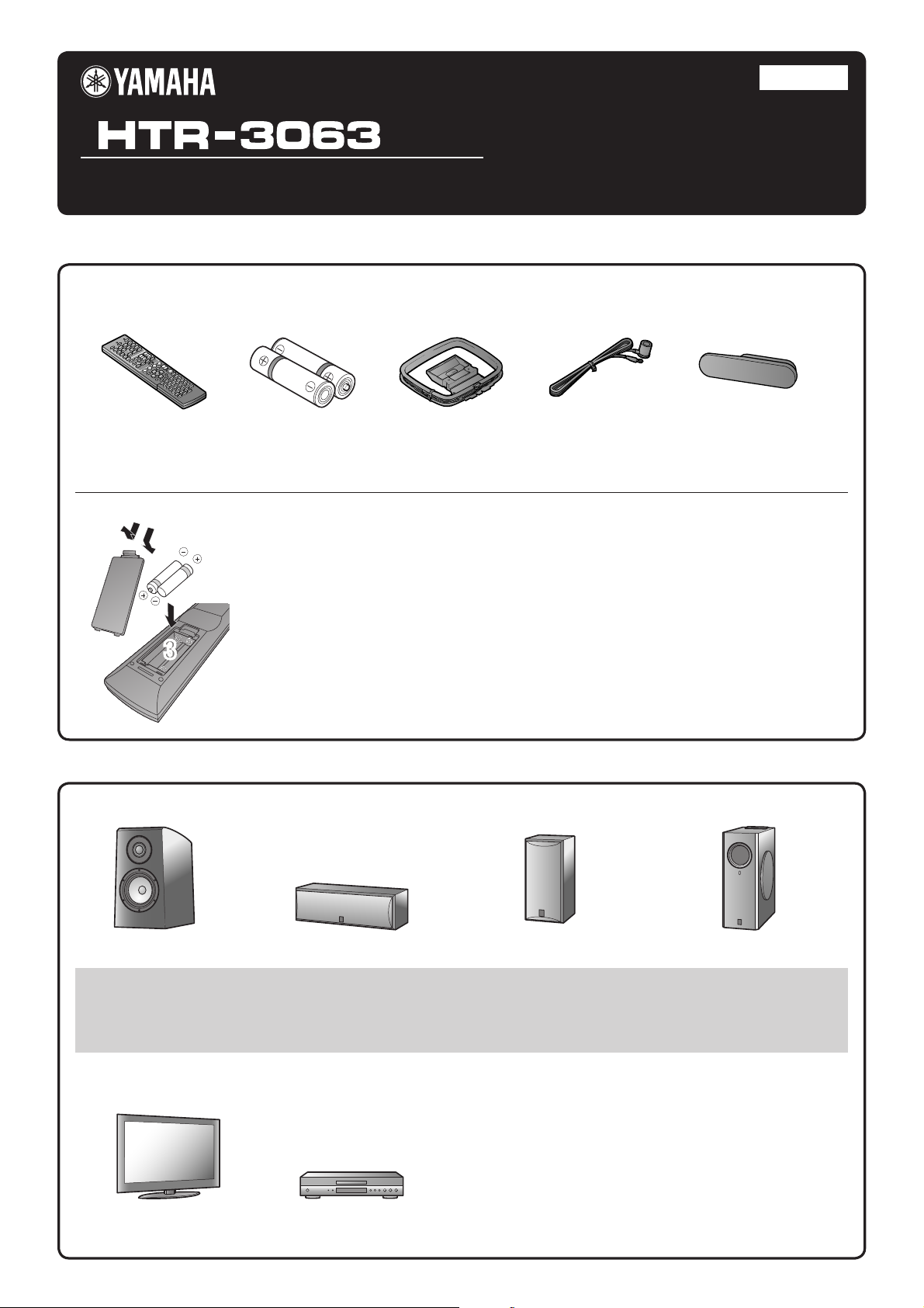
The following accessories are supplied with this product.
English
for North America
PUSH
Remote control
Batteries (2) (AAA, R03,
UM-4)
Preparing the remote control
1
2
Take off the battery compartment cover.
1
Insert the two supplied AAA batteries into the battery case, following the polarity
2
markings.
Snap the battery compartment cover back into place.
3
3
3
Items necessary for connection
■
Speakers
AM loop antenna
Indoor FM antenna VIDEO AUX input cover
Ex. Ex. Ex. Ex.
Front speaker
Use speakers with an impedance of at least 6Ω. •
If you are using a CRT TV, we recommend that you use magnetically shielded speakers.•
Prepare at least two speakers (for front). The priority of the other speakers is as follows:•
1 Two surround speakers
2 One center speaker
Center speaker
Surround speaker
External components Cable
Cables for connecting external components•
(may differ depending on the devices you are connecting)
Speaker cables•
(a quantity to match the number of speakers you are connecting)
Audio pin cable•
(for subwoofer)
TV
Playback device such as BD
(Blu-ray Disc)/DVD players
- 1 -
Active subwoofer
Page 2
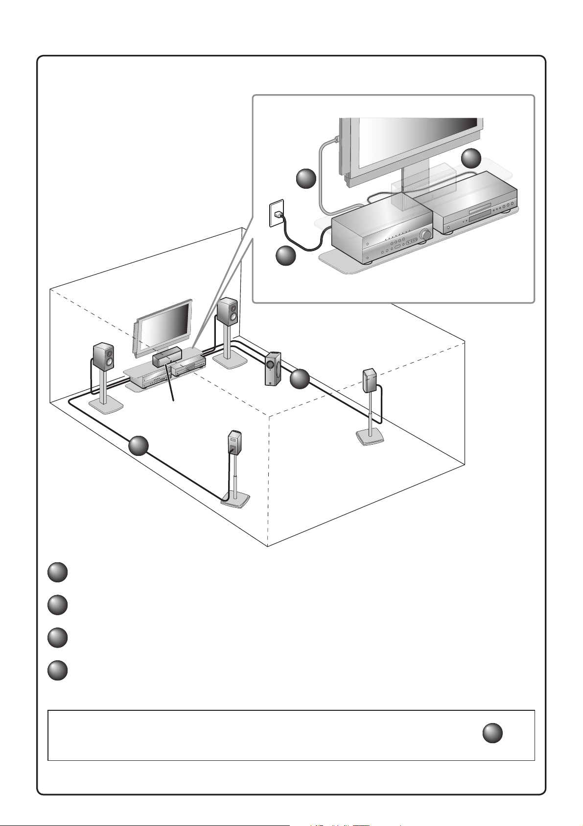
Connect and install as follows the rst time you use this unit.
See the following explanations for the connections for each number.
2
4
This unit
Front
speaker R
TV
3
BD/DVD player
(recorder)
Front
speaker L
Center speaker
1
Connect the speakers
1
Connect a TV
2
Subwoofer
Surround
speaker R
1
Surround
speaker L
Connect playback device such as BD/DVD players and recorders
3
Connect the AC power cord, and turn the power on
4
When connection and installation is nished, set up the speaker parameters
- 2 -
5
.
Page 3
FRONT
KERS
FRONT
KERS
CENTER
SURROUND
SPEAKE
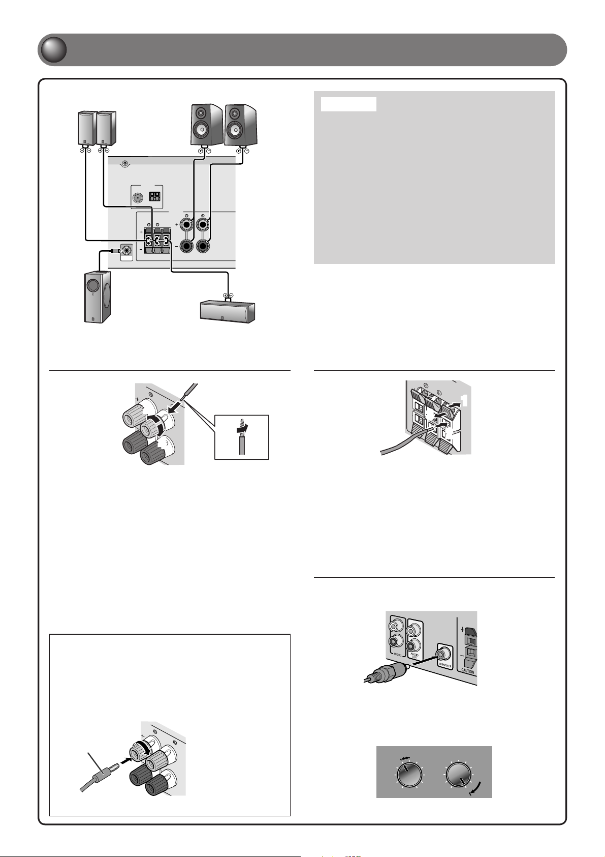
Connect the speakers
1
Surround speaker
R L
ANTENNA
FM
GND
AM
SPEAKERS
CENTER
SURROUND
SUBWOOFER
Subwoofer Center speaker
Connecting front speakers
Front speaker
R L
FRONT
Caution:
Remove the AC power cord of this unit from the power outlet •
before connecting the speakers.
Generally speaker cables consist of two parallel insulated •
cables. One of these cables is a different color, or has a
line running along it, to indicate different polarity. Insert the
different colored (or lined) cable into the “+” (positive, red)
terminal on this unit and the speakers, and the other cable into
the “-” (minus, black) terminal.
Be careful that the core of the speaker cable does not touch •
anything or come into contact with the metal areas of this
unit. This may damage this unit or the speakers. If the speaker
cables short circuit, “CHECK SP WIRES!” will appear on the
front panel display when this unit is switched on.
When connecting 6Ω speakers, set the speaker impedance to •
6Ω on this unit before making connections. Refer to Owner’s
Manual for information on settings.
Connecting center speakers /
surround speakers
3
2
1
4
Remove approximately 10mm of insulation from
1
the ends of the speaker cables, and twist the bare
wires of the cables together rmly so that they will
not cause short circuits.
Loosen the speaker terminals.
2
Insert the bare wire of the speaker cable into the
3
gap on the side of the terminal.
Tighten the terminal.
4
Connecting the banana plug
(Except U.K., Europe, Asia and Korea
models)
Tighten the knob, and then insert the banana plug
into the end of the terminal.
Banana plug
1
3
2
Press the tab on the speaker terminal down.
1
Insert the speaker cable end into the terminal.
2
Lift the tab to x the speaker cable in place.
3
Connecting the subwoofer
Connect the subwoofer input jack to the SUBWOOFER
1
jack on this unit with an audio pin cable.
Set the subwoofer volume as follows.
2
Volume: Set to approximately half volume (or slightly less than
half).
Crossover frequency (if available): Set to maximum.
CROSSOVER/
VOLUME
HIGH CUT
- 3 -
MIN MAX
Subwoofer examples
MIN MAX
Page 4
C
O
M
PONEN
T
P
R
P
B
Y
O
C
VVV3V
5
C
O
AXIAL
(
C
D
)
C
O
E
O
C
OMO
VID
E
O
(
B
D/DVD
)
H
DMI2
O
U
MONITOR
O
U
T
P
R
P
B
Y
D
O
C
K
COO
V
IDE
O
P
R
Y
O
C
(
)
A
V
1
A
V
2
A
V
3
A
V
4
A
V
5
A
U
D
I
O
A
U
D
I
O
2
C
O
AXIAL
(
C
D
)
C
O
AXIAL
O
PTI
A
V
O
U
AUD
I
O
O
U
O
HDMI1
(
B
D/DVD
)
3
O
C
P
R
P
B
Y
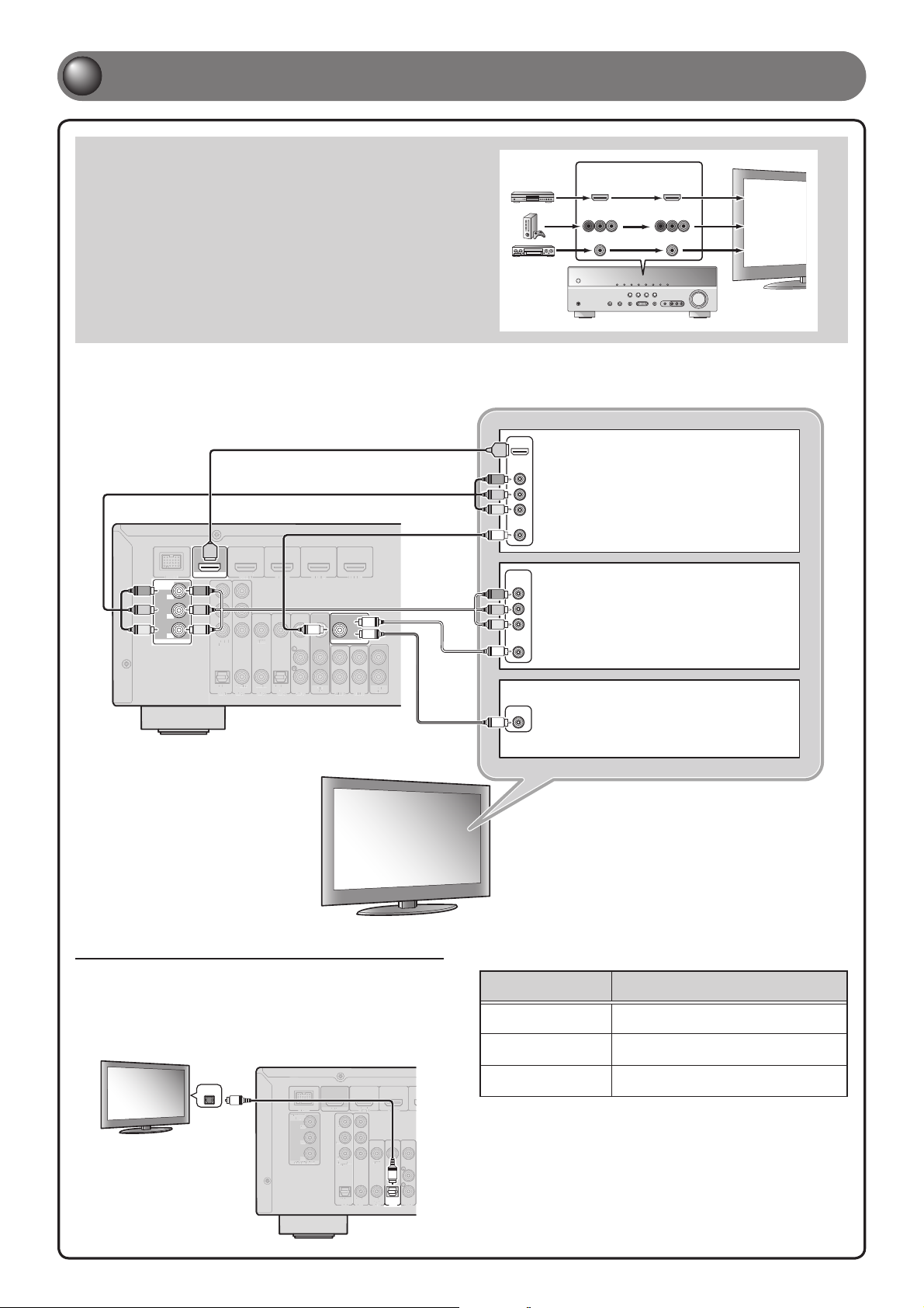
Connect a TV
2
Video input to this unit is output to a TV using output jacks of the
same kind.
When you have made connections using different types of video
such as HDMI and component video, make the same connection
with your TV. When viewing, be sure to switch the input source on
your TV to match the playback device.
If your TV has multiple inputs, connect with the following priority (A to C).
HDMI
HDMI
COMPONENT
VIDEO
P
R
P
B
Y
VIDEO
V
HDMI
(
)
BD/DVD
OUT
HDMI
DOCK
COMPONENT
VIDEO
P
P
R
P
B
Y
MONITOR OUT
R
P
R
P
B
P
B
Y
Y
COMPONENT
VIDEO
P
R
P
B
Y
HDMI 1
HDMI 2 HDMI 3
VIDEO
HDMI 4
MONITOR OUT
V
V
V
P
R
P
B
Y
V
COMPONENT
VIDEO
VIDEO
Input Output
HDMI
COMPONENT
VIDEO
VIDEO
HDMI
COMPONENT
VIDEO
VIDEO
A When using an HDMI
compatible TV.
B When using a component
video input-compatible TV.
HDMI input
Component
video input
Video input
COAXIAL
COAXIAL
OPTICAL
OPTICAL
AV 1
CAL
(CD)
AV 2
AV 3
AV
(
)
TV
OUT
AV 4
AV 5
AUDIO
OUT
AUDIO 2
AUDIO 1
Listening to TV audio
To playback TV audio on this unit, connect the TV audio output to this
unit.
Connect the following input jacks, matching the audio output jacks on
your TV. When viewing your TV, select the appropriate input source on
this unit.
OPTICAL
Audio
output
O
COMPONENT
VIDEO
MONITOR OUT
DOCK
NT
PR
PB
Y
(
)
BD/DVD
OUT
HDMI
PR
PB
Y
COMPONENT
VIDEO
OPTICAL
HDMI 2
HDMI 1
I
VIDEO
VID
O
AV 1
O
COAXIAL
COAXIAL
OPTICAL
(CD)
(
)
TV
AV 5
AV 4
AV 3
AV 2
VIDEO
V
C When using a TV compatible
with video input only.
Audio output from TV
Optical digital output AV1 or AV4
Coaxial digital output AV2 or AV3
Analog output One of AV5, AUDIO1, or AUDIO2
Connecting to AV4 allows you to playback TV audio just by pressing ✽
the “TV” under “SCENE” key.
Input jack on this unit
- 4 -
Page 5
(
T
V
)
A
V
3
A
V
4
A
U
D
I
O
1
A
U
D
I
O
2
(
C
)
C
O
P
T
C
A
L
O
U
T
U
O
O
U
T
O
C
O
M
ENT
O
HDMI2HDMI
H
DMI
4
O
T
OOO
U
OOO
U
P
B
Y
O
C
P
R
P
B
Y
O
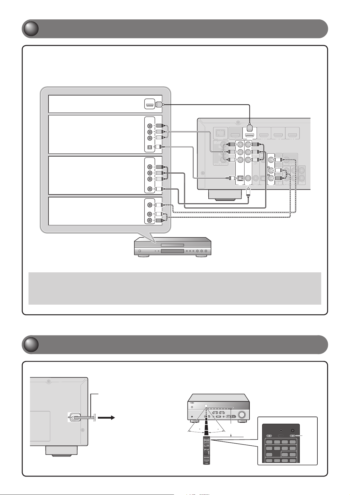
Connect playback device such as BD/DVD players and recorders
3
If your playback device has multiple audio/video outputs, connect with the following
priority (A to D) to enjoy a higher quality sounds and images.
A When playback device is
capable of HDMI output
B When playback device is
capable of component video
output (with optical digital
audio output)
C When playback device is
capable of component video
output (with coaxial digital
audio output)
D
When playback device is
capable of video output (with
analog audio output) only
HDMI
COMPONENT
VIDEO
OPTICAL
COMPONENT
VIDEO
COAXIAL
VIDEO
AUDIO
HDMI
P
R
P
B
Y
O
P
R
P
B
Y
C
V
L
R
DOCK
COMPONENT
PON
VIDEO
P
P
MONITOR OUT
R
B
Y
HDMI
(
)
BD/DVD
OUT
U
HDMI
P
R
P
R
P
B
P
B
Y
Y
COMPONENT
VIDEO
O
OPTICAL
AV 1
COAXIAL
AV 2
HDMI 1
C
P
P
Y
VIDEO
COAXIAL
(CD)
AV 3
R
B
D
HDMI 2 HDMI 3
O
I
OPTICAL
(
)
TV
AV 4
AV 5
HDMI 4
3
V
MONITOR OUT
L
R
AV
OUT
AUDIO
OUT
AUDIO 2
AUDIO 1
When playback, select the corresponding input source the jack is connected.•
Connecting to HDMI1 allows you to select the HDMI input just by pressing the “BD/DVD” under “• SCENE” key.
Connecting to AV3 allows you to select the AV3 input just by pressing the “CD” under • “SCENE” key.
If necessary, you can connect components that cannot be connected using the above methods, such as devices that output video from •
component video output jacks and audio from analog output jacks. Refer to Owner’s Manual for details.
Connect the AC power cord, and turn the power on
4
Be sure to aim the remote control directly at the remote control sensor
AC power cord
To the power outlet.
on this unit during operation.
30
within
30
20 ft
TRANSMIT
SOURCE
SLEEP
HDMI
1234
AV
1234
AUDIO
125
V-AUX
[ A ] [ B ] DOCK
CODE SET
RECEIVER
Press
- 5 -
Page 6
7
856
9
010
3
C
ENT
T
V
O
L
T
U
U
S
C
O
PTION
OLU
M
E
C
SUC
O
S
G
AUD
I
O
S
S
L
E
3
4
3
1
5
V
AUX
U
F
O
O
A
M
SUG
MOVIE
M
U
SIC
S
TER
E
O
DVD
VCDRADI
O
MUT
E
O
MEN
U
O
U
MEN
U
S
SOU
C
C
O
ESE
T
[A]
[B]
D
O
C
K
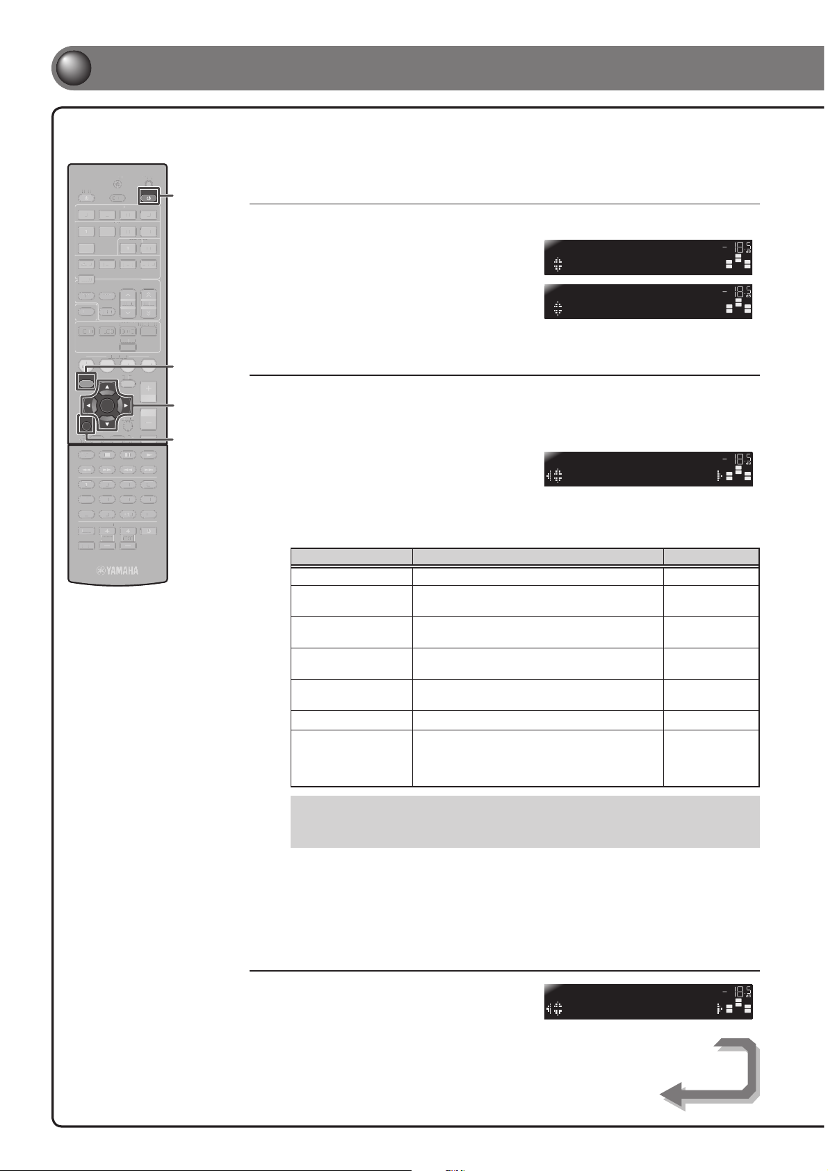
Set up speaker parameters
5
When you nish connecting, adjust the status, size, and volume
of each speaker so that the output is normal.
CODE SET
D
TRANSMIT
SOURCE
1234
1 2
1234
V-AUX
TUNER
FM
M
INFO
MOVIE MUSIC
BD
DVD
SETUP
RETURN
TOP
MENU
REC
1234
90
INPUT
MUTE
SLEEP
EP
HDMI
AV
AUDIO
125
[ A ] [ B ] DOCK
AM
PRESET
MEMORY
SUR. DECODE
ENHANCER
STEREO
STRAIGHT
SCENE
TV
CD
T
OPTION
VOLUME
V
ENTER
DISPLAY
POP-UP
MENU
7856
10
TV
TV VOL TV CH
V
VCH
RECEIVER
2
TUNING
RADIO
MUTE
ENT
RECEIVER A
SETUP
Cursor
ENTER
RETURN
STEP 1: Display the setting menu
Press RECEIVER A on the remote control to switch this unit on.
1
Press SETUP on the remote control.
2
Check that “Speaker Setup” appears
3
and press ENTER.
This completes step 1.
STEP 2: Set the speaker status and size
The settings in step 2 are not necessary with the following speaker con guration:
• Front speaker: woofer diameter is 16 cm or larger
• Center/surround speakers: woofer diameter is 16 cm or smaller
• Subwoofer: connected
Check that “Con g” appears and
4
press ENTER.
Use Cursor B / C to select the speaker (subwoofer) you want to con gure,
5
and then use Cursor D / E to select speaker status and size.
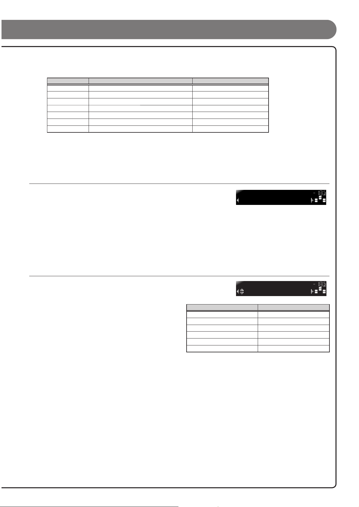
Information Description Setting
Subwoofer
Front
Center
Sur. LR
Crossover
SWFR Phase
Extra Bass
SETUP
Speaker Setup
SP SET
Config
CONFIG
Subwoofer;;Yes
Sets the subwoofer status. Yes/None
Selects the size (sound reproduction capacity) of
the front speakers.
Selects the size of the center speakers. Choose
“None” if you do not have a speaker connected.
Selects the size of the surround speakers. Choose
“None” if you do not have a speaker connected.
Audio with a frequency below this limit will be
output from the subwoofer or the front speakers.
Switchs the phase of the subwoofer. NRM/REV
Selects whether to play front channel
low-frequency components through either the front
speakers or the subwoofer (Off), or through both
the subwoofer and front speakers (On).
Small/Large
None/Small/Large
None/Small/Large
40 Hz to 200 Hz
On/Off
VOL.
SW
C
R
L
SL SR
VOL.
SW
C
R
L
SL SR
VOL.
SW
C
R
L
SL SR
Whether or not you set “Crossover,” “SWFR Phase,” and “Extra Bass” is optional. Check •
how the effects sound and then con gure them to your liking.
Use the following as a guide when setting speaker sizes. •
When you have completed the settings for one speaker, repeat the same procedure for all speakers
to complete settings.
Press RETURN when setting is complete.
6
This completes step 2.
STEP 3: Set the distance from the listening point
Press Cursor C to display “Distance”
7
and press ENTER.
DIST
Unit;;;;;;feet
- 6 -
VOL.
Continues to
the next page
SW
C
L
SL SR
R
Page 7
Press Cursor B / C to select the speaker (subwoofer) that you want to con gure, and press Cursor D / E
8
to set the distance.
If necessary, you can change the setting units under “Unit.”
Information Description Setting
Unit
Front L
Front R
Center
Sur. L
Sur. R
SWFR
When you have completed the settings for one speaker, repeat the same procedure for all speakers to complete settings.
Press RETURN when setting is complete.
Switches between setting units (feet / meters). feet (ft) / meters (m)
Front speaker L 1.0 ft to 80.0 ft (0.30 m to 24.0 m)
Front speaker R 1.0 ft to 80.0 ft (0.30 m to 24.0 m)
Center speaker 1.0 ft to 80.0 ft (0.30 m to 24.0 m)
Surround speaker L 1.0 ft to 80.0 ft (0.30 m to 24.0 m)
Surround speaker R 1.0 ft to 80.0 ft (0.30 m to 24.0 m)
Subwoofer 1.0 ft to 80.0 ft (0.30 m to 24.0 m)
9
This completes step 3.
STEP 4: Playback a test tone
Press Cursor C repeatedly to display “Test Tone” and press ENTER.
10
Use Cursor D / E to select “On.”
TEST
>Off On
11
A test tone plays back from the speakers as soon as you select “On.” The test tone plays back in a clockwise fashion. Only speakers
con gured for use in procedure 5 output the test tone.
Check that the test tone is playing back and press RETURN.
12
This completes step 4.
STEP 5: Adjust the volume
Press Cursor B repeatedly to display “Level” and press ENTER.
13
Use Cursor B / C to switch the speaker that is
14
outputting the test tone, looking for speakers with
a different volume level to the others.
The front panel display shows the speaker that is outputting
the test tone.
Only speakers con gured for use in procedure 5 output the
test tone.
If you nd a speaker with a different volume level to the others, use Cursor D / E to adjust the volume. Use
15
Front speaker L or R as a default when adjusting volumes.
Information Speakers
FL
FR
C
SL
SR
SWFR
LEVEL
d
FL----d----
Front speaker L
Front speaker R
Center speaker
Surround speaker L
Surround speaker R
Subwoofer
VOL.
SW
C
R
L
SL SR
VOL.
SW
C
R
L
SL SR
To raise the volume: Press Cursor E.
To lower the volume: Press Cursor D.
Repeat steps 14 and 15 to adjust the volume balance for all speakers to your preference.
16
Press RETURN when setting is complete.
17
Return to the previous menu.
This completes step 5.
Repeat procedures 10-12 (step 4) to stop playback of the test tone.
18
Once you have completed all settings, press SETUP to close the Setup menu.
19
- 7 -
Page 8
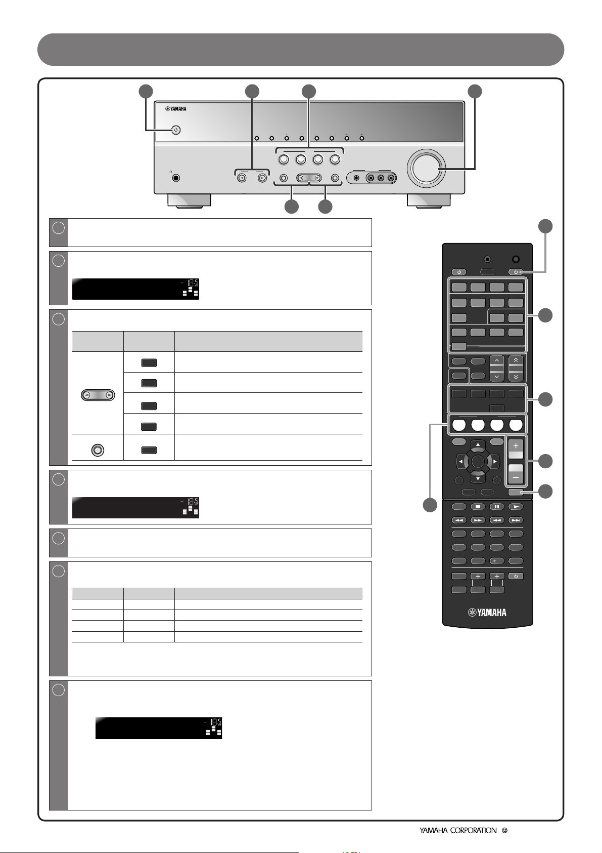
Operation guide
①
PHONES
SILENT
CINEMA
1
Switches this unit between on and standby modes
②
INPUT
⑥
MEMORY
INFO
PRESET
BD
TV
DVD
TONE
CONTROL
PROGRAM
This unit switches between on and standby mode every time you press this key.
2
Choose an input source to listen to
The name of the selected input source appears on the front panel display.
HDMI1
3
Select sound eld programs and sound decoders
Front
panel
PROGRAM
STRAIGHT
Remote
control
MOVIE
MUSIC
ENHANCER
STEREO
SUR. DECODE
STRAIGHT
VOL.
SW
C
R
L
SL SR
Description
Selects sound eld programs optimized for viewing
movies, dramas, and sports.
Selects sound eld programs optimized for
appreciating music.
Selects settings for stereo playback or enhancers for
compressed audio.
Selects surround decoders such as Dolby Pro Logic II.
Switches to straight decoding mode for faithful
reproduction of audio / video.
4
Adjusts the volume level
The current volume level is displayed on the front panel display.
Volume -18.5dB
VOL.
SW
C
R
L
SL SR
④
FM AM
SCENE
CD
STRAIGHT
TUNING
VOLUME
RADIO
AUX
VIDEO
VIDEO
PORTABLE
AUDIO
③⑦
①
CODE SET
TRANSMIT
⑥
SOURCE
1234
1234
V-AU X
[ A ] [ B ] DOCK
TUNER
FM
AM
INFO
MEMORY
MOVIE MUSIC
SCENE
BD
TV
DVD
SETUP
ENTER
RETURN
TOP
MENU
REC
SLEEP
HDMI
AV
AUDIO
125
PRESET
ENHANCER
STEREO
STRAIGHT
CD
OPTION
DISPLAY
POP-UP
MENU
RECEIVER
TUNING
SUR. DECODE
RADIO
VOLUME
MUTE
②
③
④
⑤
5
Mutes the sound
The indicator blinks while the sound is muted.
6
Switches between input settings
You can switch input sources and sound eld programs with a single key.
SCENE Input Sound field program
BD/DVD HDMI 1 Straight
TV AV4 Straight
CD AV3 Straight
RADIO TUNER 5ch Enhancer
Pressing and holding this key allows you to store input sources/sound eld programs.
Press this key when this unit is in standby mode to switch on the unit. -
7
Adjusting high/low-frequency sound (Tone control)
Press TONE CONTROL to select “Treble” or “Bass.”
1
TONE
Treble 0.0dB
VOL.
SW
C
R
L
SL SR
Press PROGRAM l / h to increase the setting.
2
You can set the tone control for speakers and headphones separately. Connect the headphones when adjusting the headphone tone control.
If you set an extreme tone balance, sounds may not match those from other channels.
1234
7856
10
90
INPUT
MUTE
TV VOL TV CH
ENT
TV
©2010 Yamaha Corporation All rights reserved.
- 8 -
YC435A0/QREN1
 Loading...