

Yamaha HI-HAT STAND User Manual
HI-HAT STAND
OWNER'S MANUAL
Introduction
Thank you for purchasing this Yamaha Hi-Hat Stand.
In order to obtain maximum performance and longevity from hi-hat stand,
please read this Owner’s Manual thoroughly.
CAUTION
• To prevent the Hi-Hat Stand from coming loose during performance, tighten all securing bolts and adjustment bolts
firmly.
• To maintain smooth action, apply some grease-grade oil
(ex. lithium grease) to all of the moving parts as needed.
* Specifications and design are subject to change without notice.
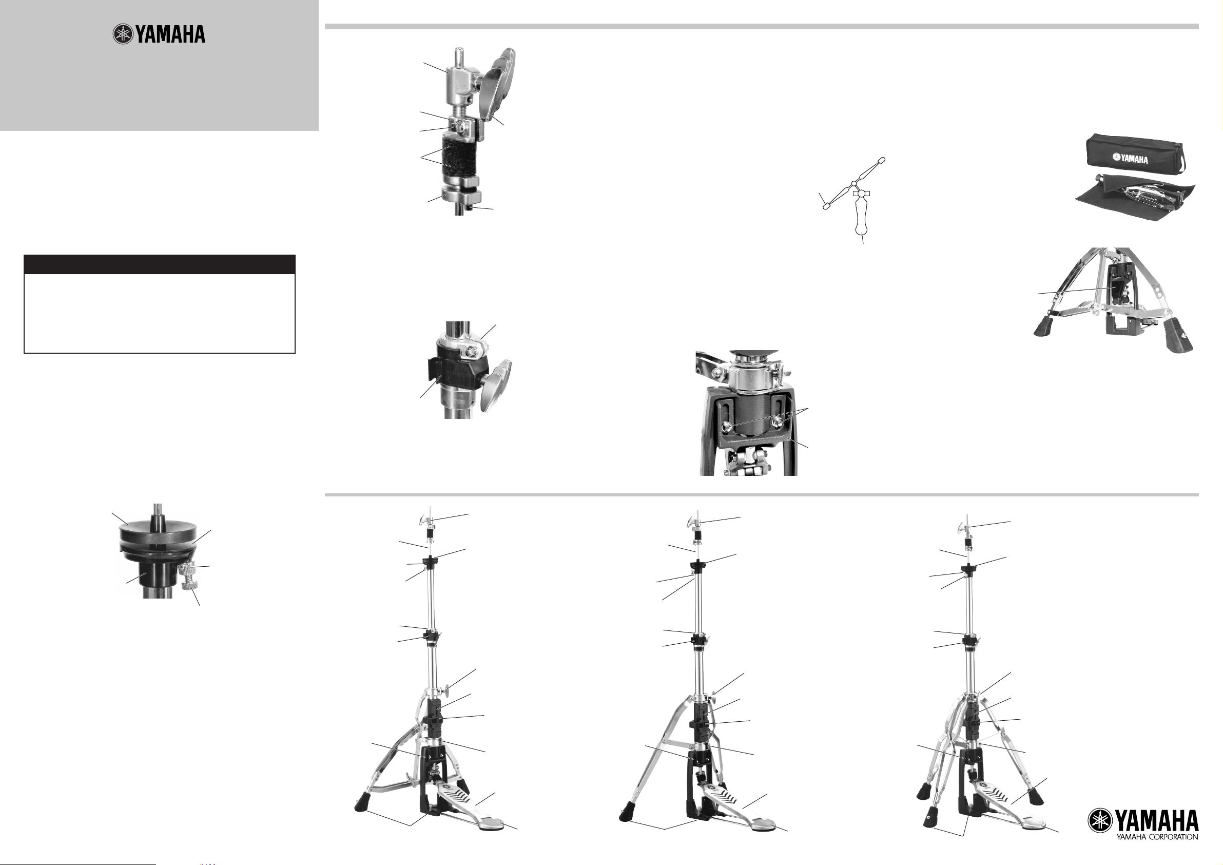
Clutch Bolt
Lock Nut
Drum Key Bolt w
Felt
Clutch Nut
Wing Bolt
Drum Key Bolt q
e Memory Clamp
After you have determined the height of the hi-hat cymbal, secure the
memory clamp at the base assembly’s pipe holder to set a “memory” of the
pipe’s position for future settings. At this time, make sure the memory clamp
fits into the pipe holder.
Use a drum key to firmly tighten the memory clamp so as to prevent the
pipe from slipping during performance.
Also, the pipe holder is equipped with a drum key holder. (The drum key is
optional.)
Memory Clamp
t Connecting Rod
Connecting the rod to the frame secures the footboard to the frame.
y Spikes
The spikes prevent the hi-hat stand from sliding forward. The unit is equipped
with four spikes, one in each of the front leg’s rubber feet and two on the
frame. Spikes located in the legs rubber feet can be extended by loosening
the drum key bolt. Those in the frame can be extended to the preferred
length by rotating the bolts clockwise.
u Adjusting Leg Position
The position of the legs (footboard) can be adjusted by loosening bolts A and B, shown in the
diagram on the right. After the position has been
determined, firmly tighten bolts A and B.
Leg
Footboard
(example: HS1100)
i Adjust the Footboard Angle
The angle adjuster can be used to increase or decrease the amount of
footboard angle by raising or lowering the adjuster.
With a drum key, loosen the two bolts on either side of the angle adjuster
then slide the angle adjuster higher or lower as needed.
After the angle has been determined, firmly tighten two bolts with a drum
key.
o Heel
A removable rubber base is attached to the underside of the heel. Remarry
the rubber, reveals a strip of Velcro™ that, provides better grip when the
stand is used on carpeted surfaces, etc.
If the Velcro does not provide sufficient grip, use the rubber.
!0 The Supplied Soft Case and Sheet
To protect the hi-hat stand's finish
from scratches, etc., werecommend
that it be placed in the supplied soft
case when transporting.
Also, please wrap the upper pipe in
the supplied sheet.
!1 A protective sheet
A protective sheet is applied to the
HS1100 to protect the finish.
Protect Sheet
q Cymbal Support Plate
To attach the bottom hi-hat cymbal first, remove the hi-hat clutch and set
the bottom hi-hat cymbal on the rubber washer. At this time, make sure
that the metal plate and the rubber washer are on the cymbal support
plate. Rotate the knurled head bolt, located under the plate, to adjust the
angle of the cymbal then secure with the fixing nut.
Rubber Washer
Metal Plate
Fixing Nut
Cymbal Support
Plate
Knurled Head Bolt
w Hi-Hat Clutch (LC-930)
The top hi-hat cymbal is fixed and held in place between the two felts of
the hi-hat clutch.
(Procedure)
1) Loosen the drum key bolt q on the clutch nut and remove the clutch
nut from the clutch bolt.
2) Remove the lower felt and place the cymbal between the upper felt
and the lower removed felt.
3) Firmly tighten the clutch nut onto the clutch bolt. Next, tighten the
drum key bolt q to lock the clutch nut. Since the drum key bolt q can
be locked with a minimum of force, be sure not to over tighten which
may cause damage to the bolt.
4) The lock nut adjusts the amount of pressure used to hold the cymbal
in place. Loosen the drum key bolt w and raise or lower the lock nut
to adjust the position. After the position has been determined, tighten
the drum key bolt w to lock the lock nut in place. The drum key bolt
w can be locked with a minimum of force so be sure not to over
tighten which may cause damage to the bolt.
Pipe Holder
r Spring Tension Adjustment
The large adjustment dial adjusts spring tension. Turning the dial to the left
increases tension while turning to the right decreases tension. Also, this
system is equipped with a tension indicator that conveniently displays the
amount of tension.
• HS1100
Hi-Hat Clutch
Hi-Hat Shaft
Fixing Nut
Knurled Head Bolt
Memory Clamp
Base Assembly
Pipe Holder
Angle
Adjuster
Spikes
Cymbal Support Plate
Bolt A
Indicator
Adjustment Dial
Bolt B
Footboard
Heel
• HS1000
Hi-Hat Shaft
Fixing Nut
Knurled Head Bolt
Memory Clamp
Base Assembly
Pipe Holder
Angle
Adjuster
Spikes
Bolt
Angle Adjuster
Hi-Hat Clutch
Cymbal Support Plate
Bolt A
Indicator
Adjustment Dial
Bolt B
Footboard
Heel
• HS950
Hi-Hat Shaft
Fixing Nut
Knurled Head Bolt
Memory Clamp
Base Assembly
Pipe Holder
Angle
Adjuster
Note) Moving parts require occasional lubrication for smooth operation.
Also, over tightening of the nylon clutch inside the base assembly’s
pipe holder may result in damage. Please use caution.
Hi-Hat Clutch
Cymbal Support Plate
Bolt A
Indicator
Adjustment Dial
Bolt B
Footboard
Spikes
Heel
Printed in Japan
 Loading...