


RLT
3–DISC VCD CHANGER
STANDBY
STANDBY
/
ON
TIMER
INPUT
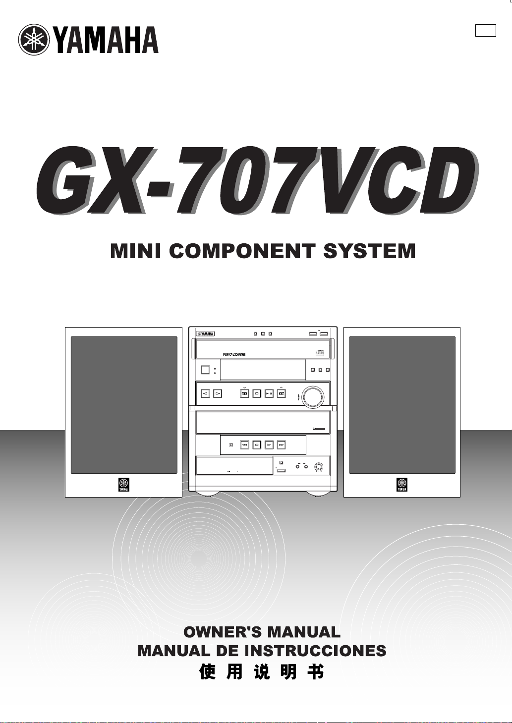
MINI COMPONENT SYSTEM GX–707VCD
AUTO REVERSE CASSETTE DECK
DIRECTION
DISC
3
DISC2DISC
1
PRESET/TUNING/BAND A/B/C/D/E
/
KARAOKE
DOLBY B NR
OPEN/CLOSE
DISC CHANGE
VIDEO CD
Version 2.0 / Playback Control
PROGRAM B.BOOST MUSIC
VOLUME
UP
DOWN
1 MIC 2
DIGITAL VIDEO
DOLBY SURROUND
PRO•LOGIC
MIC MIXING
MIN MAX
OPEN/CLOSE
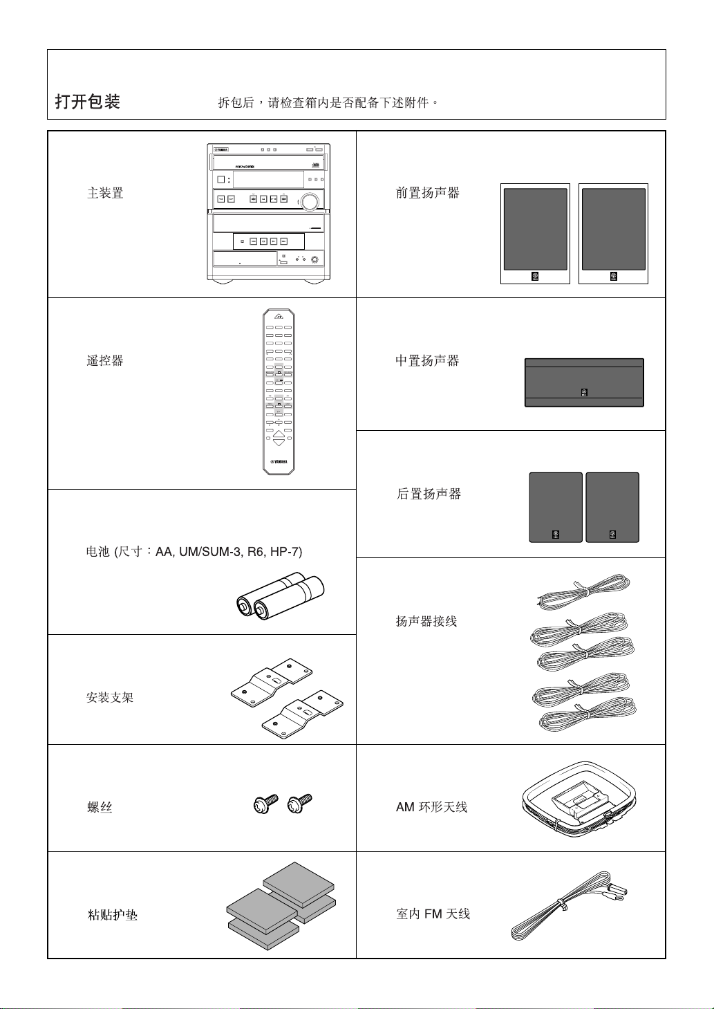
Unpacking ● After unpacking, check that the following parts are contained.
Desembalaje ● Desembale el aparato y verifique que los siguientes accesorios están en la caja.
●
● Main unit
● Aparato principal
●
● Remote control
● Control remoto
●
3–DISC VCD CHANGER
STANDBY
STANDBY
/
ON
TIMER
INPUT
MINI COMPONENT SYSTEM GX–707VCD
AUTO REVERSE CASSETTE DECK
DISC3
DISC2DISC1
PRESET/TUNING/BAND A/B/C/D/E
/
DIRECTION
DOLBY B NR
11223
44556
77889
0
PRESET
TIMEAPROGBR.TIME
EDITDDISC SKIP
RETURN
KARAOKE
TIME INDEX
REC/PAUSE
—
LEVEL
PROGRAM
SLEEP
VOLUME
POWER
TUNER+I0
VCD/CD
DIRECTION
TAPE
OPEN/CLOSE
DISC CHANGE
VIDEO CD
DIGITAL VIDEO
Version 2.0 / Playback Control
PROGRAM B.BOOST MUSIC
VOLUME
UP
DOWN
DOLBY SURROUND
PRO•LOGIC
KARAOKE
MIC MIXING
1MIC2
OPEN/CLOSE
MIN MAX
3
6
PRESET
C
MODE
E
SELECT
/
DIGEST
INTRO
TIME INDEX
TEST
CENTER/
REAR/DELAY
KEY/ECHO
MUSIC
INPUT
● Batteries (size AA, UM/SUM-3, R6, HP-7)
● Pilas (tamaño AA, tipo UM/SUM-3, R6, HP-7)
●
● Front speakers
● Altavoces delanteros
●
● Center speaker
● Altavoz central
●
● Rear speakers
● Altavoces traseros
●
● Mounting brackets
● Ménsulas de instalación
●
● Screws
● Tornillos
●
● Velcro strips
● Tiras de velcro
●
● Speaker cords
● Cables de los altavoces
●
● AM loop antenna
● Antena de cuadro AM
●
● Indoor FM antenna
● Antena interior de FM
●
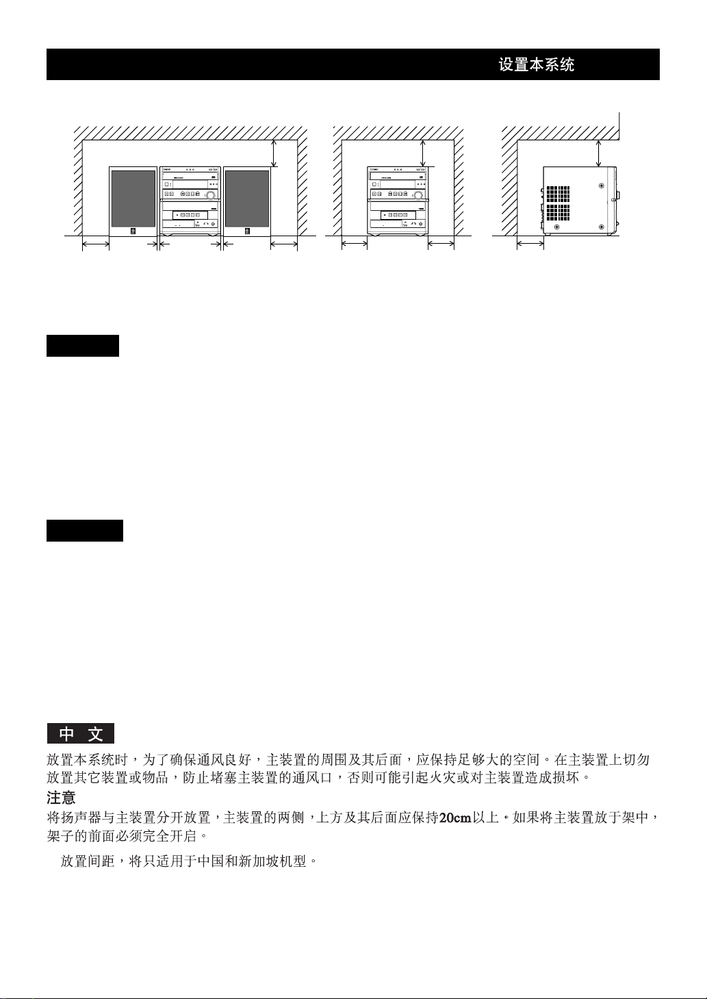
Setting this system Instalación del sistema
DISC3
OPEN/CLOSE
DISC2DISC1
DISC CHANGE
VIDEO CD
3–DISC VCD CHANGER
STANDBY
/
ON
MINI COMPONENT SYSTEM GX–707VCD
AUTO REVERSE CASSETTE DECK
STANDBY
TIMER
INPUT
DIGITAL VIDEO
Version 2.0 / Playback Control
PROGRAM B.BOOST MUSIC
VOLUME
PRESET/TUNING/BAND A/B/C/D/E
/
UP
DOWN
DOLBY SURROUND
PRO•LOGIC
DIRECTION
KARAOKE
MIC MIXING
1MIC2
OPEN/CLOSE
DOLBY B NR
MIN MAX
1 cm 1 cm
20 cm
20 cm20 cm
20 cm 20 cm
3–DISC VCD CHANGER
STANDBY
/
MINI COMPONENT SYSTEM GX–707VCD
AUTO REVERSE CASSETTE DECK
20 cm
DISC3
OPEN/CLOSE
DISC2DISC1
DISC CHANGE
VIDEO CD
DIGITAL VIDEO
Version 2.0 / Playback Control
PROGRAM B.BOOST MUSIC
STANDBY
ON
TIMER
VOLUME
PRESET/TUNING/BAND A/B/C/D/E
INPUT
/
UP
DOWN
DOLBY SURROUND
PRO•LOGIC
DIRECTION
KARAOKE
MIC MIXING
1MIC2
OPEN/CLOSE
DOLBY B NR
MIN MAX
20 cm
20 cm
English
Set this system by allowing enough spaces around and behind the main unit to assure good ventilation. Be sure not to place
another unit or any object on top of the main unit to prevent the ventilation holes from being obstructed. Otherwise, it may
cause fire or damage to the main unit.
Caution
When placing the speakers apart from the main unit, be sure to allow spaces of at least 20 cm (3-15/16”) above, behind and
on both sides of the main unit. If the main unit is put inside a rack, the front of it must be fully opened.
* The values must be applied to China and Singapore models only.
Español
Instale el sistema dejando suficiente espacio alrededor y detrás de la unidad principal para garantizar una buena circulación
de aire. No instale otro aparato o un objeto encima de la unidad principal porque obstruirá los orificios de salida de aire.
Puede provocar un fuego o dañar la unidad principal.
Precaución
Cuando instale los altavoces alejados de la unidad principal, asegúrese de dejar un espacio de por lo menos 20 cm encima,
detrás y a ambos lados de la unidad principal. Si se coloca la unidad principal dentro de un mueble, no debe cerrar la tapa
delantera.
* Los valores corresponden exclusivamente a los modelos para China y Singapur.
*
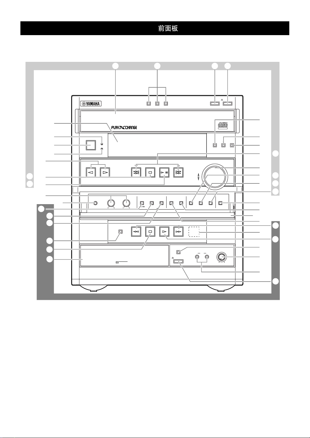
Front panel Panel delantero
Front panel
OP QR
H
U, E
T, D
0
Z
1
4
M
3
c
b
\
`
Y
8
3–DISC VCD CHANGER
STANDBY
STANDBY
/
ON
TIMER
INPUT
BASS TREBLE
PHONES
AUTO REVERSE CASSETTE DECK
DIRECTION
DOLBY B NR
DISC2DISC1
PRESET/TUNING/BAND A/B/C/D/E
MODE DOLBY NR
REC
PAUSE
DISC3
/
/
AUTO
/
MANUAL
TIMER
KARAOKE
OPEN/CLOSE
MEMORY
TIME ADJ
VIDEO CD
Version 2.0 / Playback Control
UP
DOWN
RANDOM
REPEAT
HOUR
MIN
1 MIC 2
OPEN/CLOSE
DISC CHANGE
DIGITAL VIDEO
PROGRAM B.BOOST MUSIC
VOLUME
TIME DISPLAY
MIC MIXING
MIN MAX
B
6
5
G
C, S
F
I, V
J, X
W
K
L
N
]
2
a
7
A
9
[
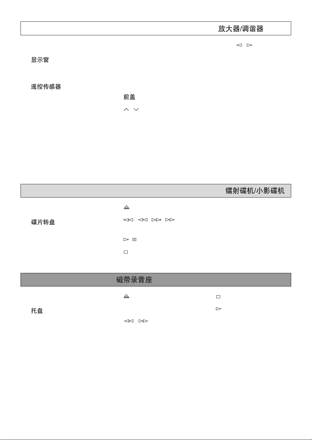
Amplifier/tuner Amplificador/sintonizador
1 Display
Visualizador
2 Remote control sensor
Sensor del control remoto
3 TIMER
4 STANDBY [p. 13]
5 B. BOOST [p. 33]
6 PROGRAM [p. 36]
9 MIC (1, 2) [p. 38]
0 BASS/TREBLE [p. 33]
A MIC MIXING [p. 38]
B Front cover
Cubierta delantera
C / [p. 22, 24]
D A/B/C/D/E [p. 24]
E PRESET/TUNING/BAND
[p. 22]
H INPUT( / ) [p. 13, 22,
26, 32]
TUNER → TAPE → VCD/CD
↑↓
AUX/MD ← VCR ← VIDEO
I HOUR [p. 10, 40]
J MIN [p. 10, 40]
K DISPLAY [p. 10, 40]
L MEMORY [p. 23, 24]
TIME ADJ [p. 10]
M STANDBY/ON [p. 13]
7 KARAOKE [p. 38]
F VOLUME [p. 33]
8 PHONES [p. 34]
G MUSIC [p. 34]
CD/Video CD player Tocadiscos de discos compactos
O Disc tray
Plato del disco
R OPEN/CLOSE [p. 13]
S ( )/ ( )
[p. 13]
P DISC (1, 2, 3) [p. 14]
Q DISC CHANGE [p. 15]
[p. 15, 20]
T / [p. 13]
U [p. 13]
N AUTO/MANUAL [p. 22]
TIMER [p. 40]
V RANDOM [p. 18]
W TIME [p. 18]
X REPEAT [p. 17]
Tape deck Platina
Y Tray
Bandeja
[p. 26]
Z MODE [p. 26]
[ OPEN/CLOSE [p. 26]
\ DIRECTION [p. 26]
] / [p. 27]
` [p. 26]
a [p. 26]
b REC/PAUSE [p. 28]
c DOLBY NR [p. 25, 28]
Remote control Control remoto
1
0
4
7
B
9
POWER
11223
44556
77889
0
TUNER+I0
PRESET
TIMEAPROGBR.TIME
EDITDDISC SKIP
RETURN
KARAOKE
TIME INDEX
REC/PAUSE
—
LEVEL
PROGRAM
SLEEP
VCD/CD
/
INTRO
DIRECTION
TAPE
VOLUME
PRESET
MODE
SELECT
DIGEST
TIME INDEX
CENTER/
REAR/DELAY
KEY/ECHO
MUSIC
3
6
C
E
TEST
INPUT
8
2
A
0
3
5
6
C
E
D
H
G
R
K
O
T
M
U
V
POWER
11223
44556
77889
0
TUNER+I0
PRESET
TIMEAPROGBR.TIME
EDITDDISC SKIP
RETURN
KARAOKE
TIME INDEX
VCD/CD
/
INTRO
PRESET
MODE
SELECT
DIGEST
TIME INDEX
W
DIRECTION
TAPE
REC/PAUSE
—
LEVEL
PROGRAM
CENTER/
REAR/DELAY
KEY/ECHO
MUSIC
3
6
C
E
TEST
F
S
J
I
K
Q
P
N
L
M
U
X
Y
SLEEP
INPUT
VOLUME
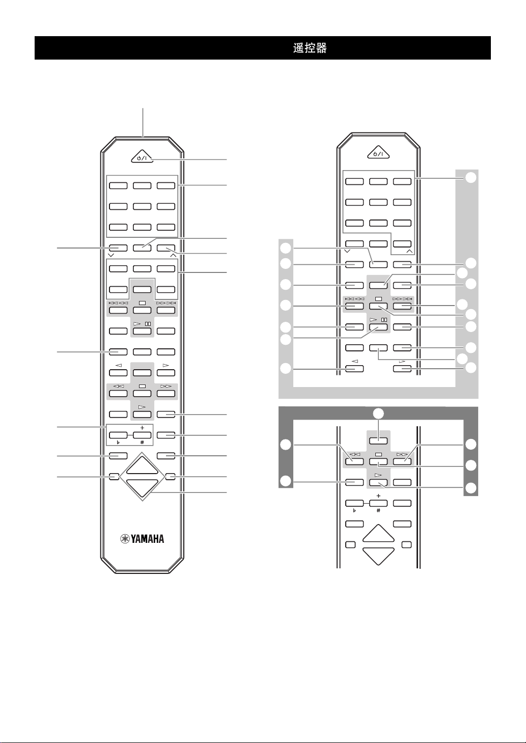
Amplifier/tuner Amplificador/sintonizador
1 Transmission window
Ventanilla de transmisión
[p. 5]
2 Numeric buttons
Botones numéricos
[p. 24]
3 A, B, C, D, E [p. 24]
4 KARAOKE [p. 38]
5 TEST [p. 11]
6 CENTER/REAR/DELAY [p. 37]
KEY/ECHO [p. 39]
7 LEVEL (–/+) [p. 11, 37, 39]
LEVEL ( / ) [p. 39]
8 POWER [p. 11]
9 SLEEP [p. 41]
0 PRESET ( / ) [p. 24]
A TUNER [p. 22]
B PROGRAM [p. 36]
C MUSIC [p. 34]
D VOLUME [p. 33]
E INPUT [p. 13, 22, 26, 32]
TUNER → TAPE → VCD/CD
↑↓
AUX/MD ← VCR ← VIDEO
CD/Video CD player Tocadiscos de discos compactos
F Numeric buttons
Botones numéricos
[p. 14]
G TIME [p. 18]
H PROG [p. 16]
I MODE [p. 14]
Tape deck Platina
U / [p. 27]
V REC/PAUSE [p. 28]
J DISC SKIP
[p. 14]
K ( )/ ( )
[p. 15, 20]
L INTRO [p. 19]
M TIME INDEX [p. 19]
N DIGEST [p. 19]
W DIRECTION [p. 26]
X [p. 26]
O RETURN [p. 20]
P SELECT [p. 20]
Q [p. 13]
R EDIT [p. 30, 31]
S R. TIME [p. 30]
T / [p. 13]
Y [p. 26]

English
Thank you for purchasing this YAMAHA product. We hope it will give you many years of trouble-free enjoyment.
For the best performance, read this manual carefully. It will guide you in operating your YAMAHA product.
Contents
Precautions....................................... 1
Features ............................................ 4
Preparations and connections........ 5
Installing batteries in the remote control............. 5
Remote control operation range ......................... 5
Setting the video output format selector
(TV MODE) switch ......................................... 5
Setting up the speakers...................................... 6
Connections........................................................ 8
Setting the clock ............................................... 10
Adjusting brightness of the display ................... 10
Speaker balance adjustment ............................ 11
CD/Video CD player operation ...... 12
Basic play ......................................................... 13
To change the disc play mode.......................... 14
To select another disc....................................... 14
To directly select the desired track ................... 14
To play the desired track (Skip) ........................ 15
To advance or reverse play rapidly (Search) .... 15
To exchange a disc (or discs) while playing
(PLAYXCHANGE) ........................................ 15
Program play .................................................... 16
Repeat play ...................................................... 17
Random play .................................................... 18
Switching the time display ................................ 18
To find the desired scene quickly
for Video CDs.............................................. 19
To get a quick overview of a track or a disc
for Video CDs.............................................. 19
Playback Control of Video CD (version 2.0)
for Video CDs.............................................. 20
Playing back a tape........................ 25
General information .......................................... 25
Basic operation................................................. 26
Winding the tape............................................... 27
Searching for the beginning of
the desired selection .................................... 27
Recording ....................................... 28
Basic recording................................................. 28
Recording from CDs
utilizing the EDIT function ............................ 30
Operating an external unit
connected to this system ........... 32
Various sound control ................... 33
General sound control ...................................... 33
Graphic equalizer ............................................. 34
Sound field processor....................................... 35
Karaoke operation.......................... 38
Using the built-in timer .................. 40
Timer play......................................................... 40
Timer recording................................................. 41
Sleep timer operation ....................................... 41
Appendix......................................... 42
Troubleshooting................................................ 42
Specifications ................................................... 44
Tuning operation ............................ 21
Automatic tuning............................................... 22
Manual tuning ................................................... 22
Automatic preset tuning.................................... 23
Manual preset tuning ........................................ 24
For basic source play, the following illustrations on top of the
pages will help you look for the section you need.
...... CD/Video CD play .......Tuning
...... Tape playback/recording

Precautions: Read this before operating your system
■ To assure the finest performance, please read this manual
carefully. Keep it in a safe place for future reference.
■ Choose the installation location of this system carefully. Avoid
placing it in direct sunlight or close to a source of heat. Also
avoid locations subject to vibration and excessive dust, heat,
cold or moisture. Keep it away from sources of hum such as
transformers and electric motors.
■ Do not operate this system upside-down. It may overheat,
possibly causing damage.
■ Never open the cabinet. If something drops into the set, contact
your dealer.
■ The openings on the main unit cover assure proper ventilation
of the main unit. If these openings are obstructed, the
temperature inside the main unit will rise rapidly. Avoid
placing objects against these openings, and install the main
unit in a well-ventilated area to prevent fire or damage.
■ Always set the VOLUME control to minimum before starting
an audio source play. Increase the volume gradually to an
appropriate level after play has started.
■ When not planning to use this system for a long period of time
(ie., vacation, etc.), disconnect the AC power plug from the
wall outlet.
■ Grounding or polarization – Precautions should be taken so
that the grounding or polarization of this system is not
defeated.
■ Do not use force on switches, controls or connection wires.
When moving the main unit, first disconnect the power plug
and the wires connected to other equipments. Never pull the
wire itself.
■ If an external appliance (TV, radio, etc.) interferes with the
operation of this system, move the main unit away from such
appliance.
■ Do not attempt to clean this system with chemical solvents as
this might damage the finish. Use a clean, dry cloth.
■ Be sure to read the “Troubleshooting” section regarding
common operating errors before concluding that this system is
faulty.
■ To prevent lightning damage, disconnect the AC power plug
and the antenna cable when there is an electric storm.
■ Do not plug the AC power plug to the wall socket before you
finish all connections.
■ Never allow metallic items (e.g. screwdrivers, tools, etc.) to
come near the tape deck’s record/playback head assembly.
Doing so may not only scratch or damage the head’s mirrorsmooth finish, it may change the magnetic characteristics of
the heads, causing a deterioration in reproduction performance
quality.
■ Although the tape deck’s record/playback heads are of high
quality with outstanding reproduction characteristics, they can
get dirty through the use of old tapes or from dust
accumulation over time. This can have a serious effect on
reproduction quality. Clean the heads regularly with
commonly available head cleaners or with cleaning solutions.
■ The voltage to be used must be the same as that specified on
this system. Using this system with a higher voltage than
specified is dangerous and may result in a fire or other types of
accidents causing damage. YAMAHA will not be held
responsible for any damage resulting from use of this system
with a voltage other than specified.
■ The sound level at a given volume setting depends on speaker
location and other factors. Care should be taken to avoid
exposure to sudden high levels of sound, which may occur
when turning this system on with the volume control setting at
high. Also avoid exposure to continuous high levels of sound.
■ Sudden temperature changes and storage or operation in an
extremely humid environment may cause condensation inside
the cabinet. Condensation can cause this system to
malfunction.
To eliminate condensation:
• Pickup
Leave the power on with no disc loaded until normal play
becomes possible (about 1 hour).
• Tape head
Leave the power on with no tape loaded until normal
playback becomes possible (about 1 hour).
Note:
If condensation forms on the tape head, dirt or dust may
accumulate during use.
• Remote control
Wipe off condensation on the transmission window with a
soft cloth before operating this system.
■ The carousel will turn when you open the disc tray by pressing
OPEN/CLOSE; therefore, make sure the carousel stopped
moving completely before you perform further operations such
as placing or removing a disc from the disc tray. Otherwise,
you may cause damage to your discs, or you might injure
yourself.
English
E-1
Precautions: Read this before operating your system
This system is not disconnected from the AC power source as
long as it is connected to the wall outlet, even if this system
itself is turned off. This state is called the standby mode.
In this state, this system is designed to consume a certain
amount of power.
Note
Please check the copyright laws in your country to record
from records, compact discs, radio, etc. Recording of
copyright materials may infringe copyright laws.
CAUTION FOR CARRYING THE MAIN UNIT
Be sure not to carry or tip the main unit with discs
in it.
CAUTION FOR MOVING THE MAIN UNIT
Before moving the main unit, first remove all discs from the
disc tray and close the tray by pressing the
OPEN/
CLOSE button. After you confirm that “NO DISC” lights up
on the display, turn this system into the standby mode by
pressing the STANDBY/ON switch, and then disconnect the
power plug from the AC outlet.
Voltage Selector (China and General models only)
The voltage selector on the rear panel of the main unit must
be set for your local main voltage BEFORE plugging into the
AC main supply.
Voltages are 110/120/220/240 V AC, 50/60 Hz.
WARNING
To reduce the risk of fire or electric shock, do not expose this
system to rain or moisture.
To avoid electric shock, do not open the cabinet. Refer
servicing to qualified personnel only.
CAUTION
Use of controls or adjustments or performance of procedures
other than those specified herein may result in hazardous
radiation exposure.
As the laser beam used in this unit is harmful to the eyes, do not
attempt to disassemble the cabinet. Refer servicing to qualified
personnel only.
This system is classified as a
CLASS 1 LASER PRODUCT
LASER KLASSE 1 PRODUKT
LUOKAN 1 LASERLAITE
KLASS 1 LASER APPARAT
CLASS 1 LASER product.
The CLASS 1 LASER
PRODUCT label is located on
the rear exterior.
Laser component in this product is capable of emitting
radiation exceeding the limit for Class 1.
FREQUENCY STEP switch
(China and General models only)
Because the interstation frequency spacing differs in different
areas, set the FREQUENCY STEP switch (located at the
rear) according to the frequency spacing in your area.
Be sure to change the setting of this switch with the AC
supply lead of this system disconnected from the AC outlet.
E-2
Precautions: Read this before operating your system
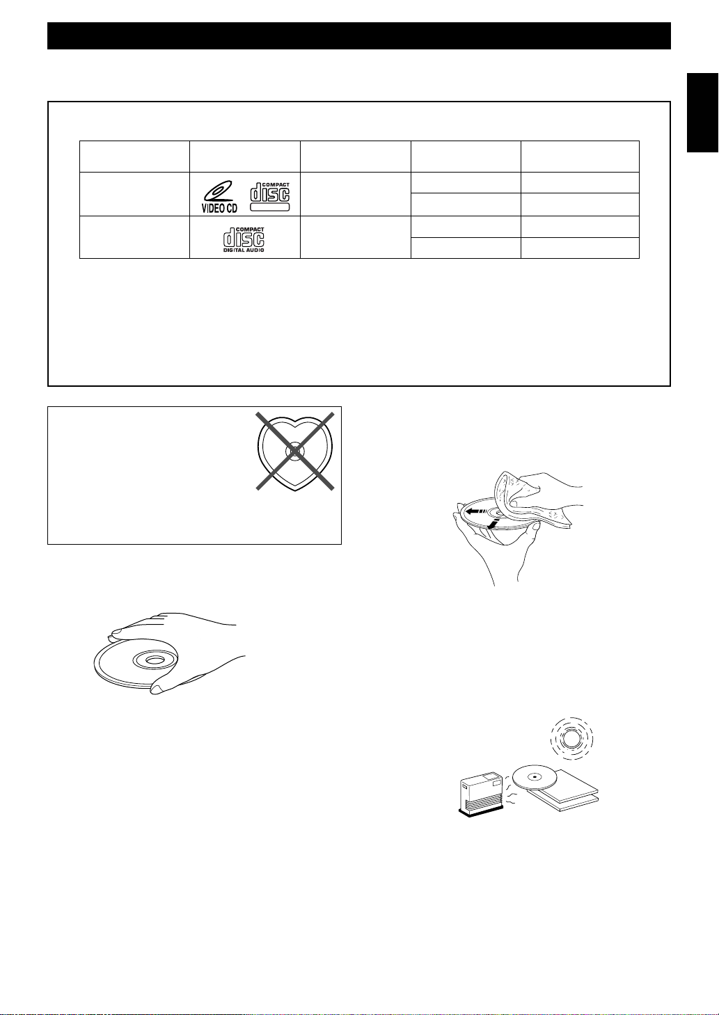
NOTES ABOUT DISCS
The CD/Video CD player in this system can play discs of the following types only.
Type of disc
Video CD
CD
Never attempt to play a disc other than specified above with the CD/Video CD player because it may cause a damage to this system.
VIDEO CD
Video CDs are classified into two types, version 1.1 and 2.0. The CD/Video CD player can play both types.
Video CD (version 1.1): With the same operation as compact discs, you can enjoy sounds and pictures (movies).
Video CD (version 2.0): In addition to a normal play which is the same as version 1.1, you can enjoy a Playback Control operation.
(For details on Playback Control, refer to page 20.)
To prevent a malfunction of this
system:
• Do not use any nonstandard shaped disc
(heart etc.) available on the market
because it might damage the system.
Mark printed
on the disc
DIGITAL VIDEO
Type of signal
recorded
Sound
+
Picture (Movie)
Sound only
• Discs are not affected by small particles of dust or fingerprints
Size (Dimension)
12 cm
8 cm (Single type)
12 cm
8 cm (Single type)
on their playing surface, but even so they should be kept clean.
Wipe by using a clean, dry cloth. Do not wipe with a circular
motion; wipe straight outward from the center.
Maximum possible
play time
74 minutes
20 minutes
74 minutes
20 minutes
English
• Do not use a disc with tape, seals, or
paste on it. If you use such a disc, a disc may get stuck
in the system, or damage to the system may result.
Notes about handling discs
• Always handle the disc with care so that its surface is not
scratched.
• Discs are not subjected to wear during play, but damage to the
disc surface when the disc is being handled can adversely
affect the disc’s play.
• Be sure to use a felt-tip pen or similar writing tool when
writing on the label side of the disc. Do not use a ball-point
pen, pencil, or other hard-tipped writing tool, as these may
damage the disc and may adversely affect the disc’s play.
• Do not warp discs.
• When a disc is not currently being used, remove it from the
system and store in an appropriate case.
• Do not try to clean the disc’s surface by using any type of disc
cleaner, record spray, anti-static spray or liquid, or any other
chemical-based liquid because such substances might
irreparably damage the disc’s surface.
• Do not expose discs to direct sunlight, high temperature or
high humidity for a long period of time because these might
warp or otherwise damage the disc.
No!
To play an 8-cm CD
Place it in the inner recessed area of the disc tray. Do not put a
normal (12-cm) CD on top of an 8-cm CD.
• When removing or storing a disc, be careful not to scratch the
playing surface.
E-3

Features
General
• 5-Speaker Multi-Channel Audio System (Two
Front, One Center and Two Paralleled Rear
Speakers)
• High Power Output
Front L, R: 100W + 100W (6Ω) RMS, 10% THD,
1 kHz
Center: 100W (6Ω) RMS Output Power, 10%
THD, 1 kHz
Rear: 30W (6Ω) RMS Output Power, 10%
THD, 1 kHz
• 4 External Audio/Video Component Connecting
Capability
• Multi-Use Timer/Sleep Timer
• SUBWOOFER Output for Low Frequency
Expansion
• Remote Control Capability
• BASS BOOST
• 5-Band Spectrum Analyzer
• DOLBY PRO LOGIC and DOLBY 3 STEREO
Decoding
• Sound Field Processing (HALL and YMERSION)
• Test Tone Generator for Easier Speaker Balance
Adjustment
• 3 Preset Graphic Equalizer Modes (ROCK, POPS
and JAZZ)
CD/Video CD Player
• 3-Disc Carousel Auto-Changer for Video CDs and
Compact Discs
• PLAY
X
CHANGE
Disc changing while playing
• 20-Track Random Access Programming
• Repeat Play for Single Track/Entire Disc/All
Discs
• Random Sequence Play
• Playback Control Function Available for Video
CD (version 2.0)
• Quick Overview of a Track and a Disc with a
Touch of the DIGEST and INTRO Buttons
• Time Index Function
Tape Deck
• Automatic Synchronized Recording with CD or
Video CD
• EDIT Function Useful for Recording CD(s)
• Automatic Reverse
• Dolby B Type Noise Reduction System
Tuner
• 40 Station Preset Tuning
• Video Output Format Selector (TV MODE)
Switch
• Balance control for the left and right main
speakers in DOLBY PRO LOGIC mode
E-4
• Automatic Preset Tuning
Karaoke Functions
• 4 Modes for Singing Karaoke
• 2 Microphone Connecting Capability
• Mic Mixing, Echo Level and Key Control
Capability
• Karaoke Sound Recording Capability (Recording
Your Singing Voice and Karaoke Effects with the
Music Source)
Preparations and connections
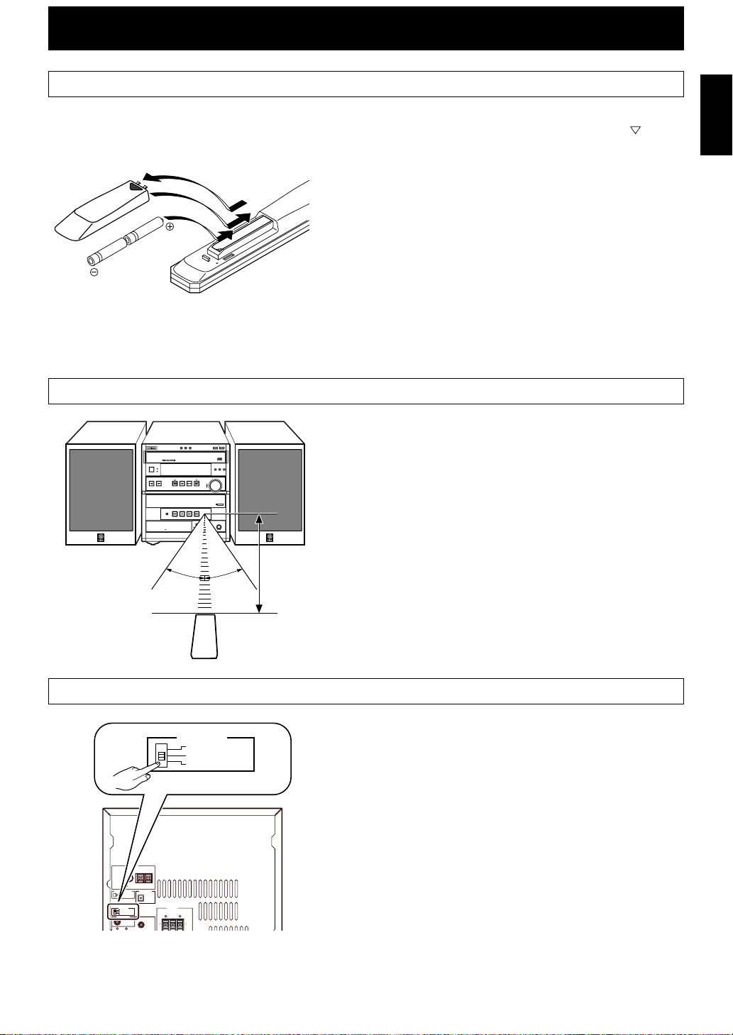
Installing batteries in the remote control
1Turn the remote control over and remove the battery
compartment cover by sliding it in the direction of the
2Insert the batteries (AA, R6, UM-3 type) according to the
1
polarity markings on the inside of the battery compartment.
3Attach the battery compartment cover.
3
2
Notes
• Be sure the polarities are correct. (see the illustration inside the battery
compartment.)
• Remove the batteries if the remote control is not used for an extended
period of time.
• If batteries leak, dispose of them immediately. Avoid touching the leaked
material or letting it come in contact with clothing, etc. Clean the battery
compartment thoroughly before installing new batteries.
• Be sure to use the same type of batteries.
• Do not use a new battery and an old battery together.
Remote control operation range
Notes
• The area between the remote control and the main unit must be clear of
large obstacles.
• Do not expose the remote control sensor to strong lighting, in particular,
an inverter type fluorescent lamp. Otherwise, the remote control may not
work properly. If necessary, position the main unit away from direct
lighting.
Battery replacement
If you find that the remote control must be used closer to the main
unit, the batteries are weak. Replace both batteries with new ones.
3–DISC VCD CHANGER
STANDBY
STANDBY
TIMER
/
ON
INPUT
MINI COMPONENT SYSTEM GX–707VCD
AUTO REVERSE CASSETTE DECK
DIRECTION
DOLBY B NR
DISC3 OPEN/CLOSE
DISC2DISC
1
PRESET/TUNING/BAND A/B/C/D/E
/
30°
DISC CHANGE
VIDEO CD
DIGITAL VIDEO
Version 2.0 / Playback Control
PROGRAM B.BOOST MUSIC
VOLUME
UP
DOWN
DOLBY SURROUND
PRO•LOGIC
KARAOKE
MIC MIXING
1 MIC 2
OPEN/CLOSE
MIN MAX
30°
English
mark.
0.2 m – 6 m
(8” – 20’)
Setting the video output format selector (TV MODE) switch
This system is designed for use with the NTSC and PAL television
formats. Set this switch to the position of the format your TV
monitor employs.
PAL: Set to this position if your TV monitor employs the PAL
format.
AUTO: Set to this position if your TV monitor can be switched in
between the PAL and NTSC formats automatically
(originally set to this mode).
NTSC: Set to this position if your TV monitor employs the
NTSC format.
FREQUENCY STEP
TV MODE
SUBWOOFER
R L
50KHZ 9KHZ
100KHZ 10KHZ
PAL
AUTO
NTSC
FM AM
ANTENNA
FM GND AM
75 UNBAL.
OUT
DIGITAL OUT
VIDEO SIGNAL
OPTICAL
MONITOR
OUT
TV MODE
PAL
AUTO
NTSC
SPEAKERS
SEE OWNER'S MANUAL
FOR CONNECTION.
REAR CENTER REAR
R L
E-5
Preparations and connections
Setting up the speakers
Front L
Rear L Rear R
Center
Front L
Center
Dialogue
Front R
(TV set)
Front R
(Subwoofer)
Rear L
Rear R
■4 channel 5 speaker configuration
This system employs a 5 speaker configuration: 2 front speakers, 2
rear paralleled speakers and a center speaker.
The front speakers are used for outputting main source sound. The
rear speakers are for effect and surround sounds when the sound
field program
PRO LOGIC or HALL is selected. The center
speaker is for center sounds (dialogue etc.) when the sound field
program PRO LOGIC or 3 STEREO is selected.
■Placing the speakers
Front speakers: On both sides of and at approximately the
same height as the TV.
Center speaker: Precisely between the front speakers.
Rear speakers: Behind your listening position, facing
slightly inward. About 1.8 m (approx. six
feet) from the floor.
Subwoofer: The position of the subwoofer is not so
(not included in) critical because low bass tones are not highly
in this system) directional. However, we recommend that
you place the subwoofer anywhere in front of
your listening position.
E-6
TV set
Velcro strip
1
2
■Mounting the center speaker
Place the speaker on top of the TV or on the floor under the TV or
inside the TV rack so that it is stable.
When placing the speaker on top of the TV, put the provided velcro
strips at two corners on both the bottom of the speaker and top of
the TV to prevent the speaker from falling.
Preparations and connections
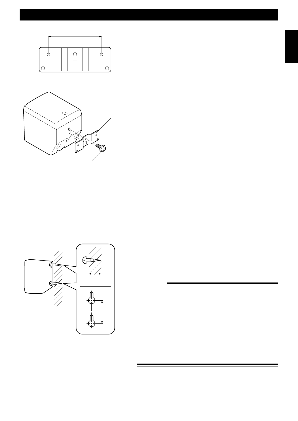
60 mm
Mounting bracket
Screw
■Mounting the rear speakers
Mount the rear speakers on a shelf, rack or on the floor, or hang
them on the wall.
To mount the rear speakers by using commercially
available speaker stands
The provided mounting bracket has 1 pair of screw holes (at an
interval of 60 mm). They are for mounting the speaker on a speaker
stand.
* These screw holes can be used with M4 screws only.
Note
It is recommended that you connect the speaker cords to the
speaker’s terminals before attaching the bracket to the speaker.
1 Attach the bracket to the bottom of the speaker by using the
provided screw so that the convex part of the bracket fits in the
grooved part of the speaker as shown left.
2 Mount the speaker on the speaker stand by using the screw holes
on the bracket.
English
Tapping screw (Available
at the hardware store)
Min.
12 mm
65 mm
Wall or wall support
To mount the rear speakers directly on the wall
If desired, you can hang the speaker on the protruding screws on
the wall without using the bracket.
Fasten screws into a firm wall or wall support as shown left, and
hang the holes of the speaker on the protruding screws.
* Make sure that the screws are securely caught by a narrow part
of the holes.
WARNING
• Each of the rear speakers weighs 0.8 kg (1 lbs. 12 oz.). Do not
mount them on thin plywood or soft wall surface material, as the
screws may come out of the flimsy surface, causing the speakers
to fall and be damaged, or result in personal injury.
• Do not fasten the speakers to the wall with nails, adhesives, or
other unstable hardware. Long-term use and vibrations may
cause them to fall.
• To avoid accidents resulting from tripping over loose speaker
cords, fix them to the wall.
• Select a proper position on the wall to mount the speaker and the
stand so that no one will injure his/her head or face with the edge
of the stand.
E-7
Preparations and connections
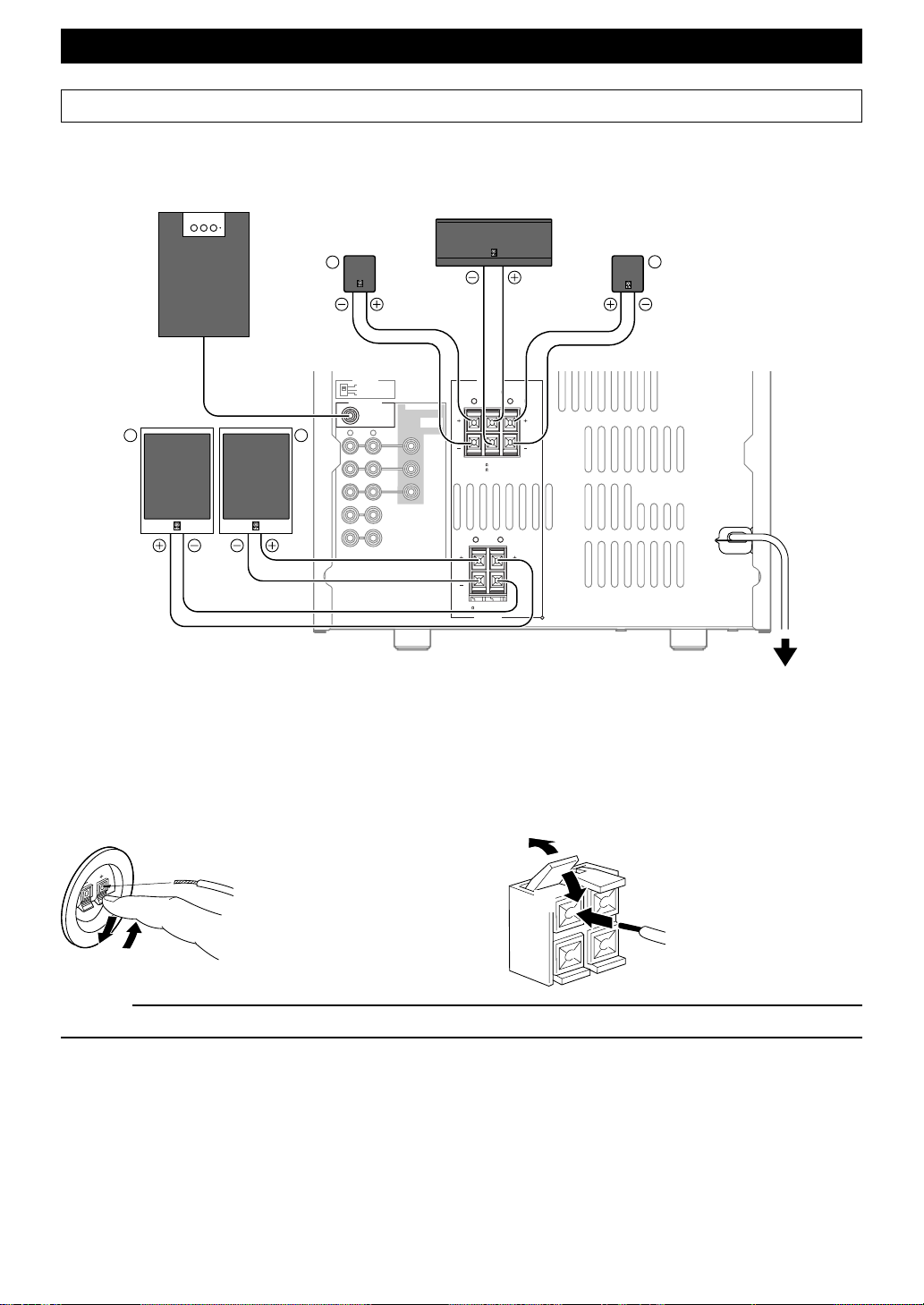
Connections
Never plug the AC supply lead of this system into the AC outlet until all connections are
completed.
Subwoofer system
(not included in this system)
Center speaker
Rear speaker
R
Rear speaker
L
INPUT
Front speakers
L R
■ Connecting speakers
TV MODE
PAL
AUTO
NTSC
SUBWOOFER
R L
VIDEO SIGNAL
OUT
OUT
AUX/MD
MONITOR
IN
OUT
OUT
VCR
IN
VIDEO
SPEAKERS
SEE OWNER'S MANUAL
FOR CONNECTION.
REAR CENTER REAR
R L
CENTER:6 MIN./SPEAKER
REAR: 12 MIN./SPEAKER
FRONT
R L
6 MIN./SPEAKER
SPEAKERS
MAINS
To AC outlet
Connect the speakers to the corresponding speaker terminals on the rear of the main unit by using the speaker cords. Make
sure that the polarity of the speaker cords is correct, that is the + and – markings are observed. If these cords are reversed,
the sound will be unnatural and lack bass.
On the speakers
Red: positive (+)
Black: negative (–)
2
1
3
1Press the tab.
2Insert the bare wire.
[Remove approx. 5mm (1/
4”) insulation from the
speaker wires.]
3Release the tab and secure
the wire.
On the main unit
Red: positive (+)
Black: negative (–)
1
3
1Pull up the tab.
2Insert the bare wire.
[Remove approx. 5mm (1/
4”) insulation from the
speaker wires.]
3Press down the tab and
2
secure the wire.
Caution
Do not let the bare speaker wires touch each other as this could damage the amplifier and/or speakers.
When connecting a subwoofer (not included in this system)
You may wish to add a subwoofer to reinforce the bass frequencies.
When connecting a subwoofer to this system, connect the SUBWOOFER OUT terminal of this system to the INPUT
terminal of the subwoofer.
* Ordinary subwoofers, including the Yamaha Active Servo Processing Subwoofer System, are designed so that both the
amplifier and subwoofer are contained in the same unit.
* The SUBWOOFER OUT terminal outputs low frequencies from the left front, center and right front channels.
(The cut-off frequency of this terminal is 200 Hz.)
E-8