

GX-707/GX-707VCD
MINI COMPONENT SYSTEM
GX-707
GX-707VCD
SERVICE MANUAL
GX-707 is composed of GX-707 (main unit) and NX-P707 (speakers).
GX-707VCD is composed of GX-707VCD (main unit) and NX-P707 (speakers).
NX-P707 is composed of NX-GX505, NX-C707 and NX-E707.
The NX-C707 and NX-E707 loudspeakers are not field serviceable and must be replaced as complete units.
IMPORTANT NOTICE
This manual has been provided for the use of authorized YAMAHA Retailers and their service personnel.
It has been assumed that basic service procedures inherent to the industry, and more specifically YAMAHA Products, are
already known and understood by the users, and have therefore not been restated.
WARNING: Failure to follow appropriate service and safety procedures when servicing this product may result in
IMPORTANT: The presentation or sale of this manual to any individual or firm does not constitute authorization, certifica-
The data provided is believed to be accurate and applicable to the unit(s) indicated on the cover. The research, engineering, and
service departments of YAMAHA are continually striving to improve YAMAHA products. Modifications are, therefore,
inevitable and specifications are subject to change without notice or obligation to retrofit. Should any discrepancy appear to
exist, please contact the distributor's Service Division.
WARNING: Static discharges can destroy expensive components. Discharge any static electricity your body may have
IMPORTANT: Turn the unit OFF during disassembly and part replacement. Recheck all work before you apply power to the
personal injury, destruction of expensive components, and failure of the product to perform as specified.
For these reasons, we advise all YAMAHA product owners that any service required should be performed
by an authorized YAMAHA Retailer or the appointed service representative.
tion or recognition of any applicable technical capabilities, or establish a principle-agent relationship
of any form.
accumulated by grounding yourself to the ground buss in the unit (heavy gauge black wires connect to this
buss).
unit.
GX-707/VCD
■ CONTENTS
TO SERVICE PERSONNEL ................................... 1—2
GX-707 PANELS ..................................................... 3—4
GX-707VCD PANELS ...................................................5
SPECIFICATIONS ......................................................... 6
INTERNAL VIEW .......................................................... 7
DISASSEMBLY PROCEDURES .......................... 8—12
VOLUME RANGE ....................................................... 13
SYSTEM CONTROL CHECK ..................................... 13
TEST MODE ................................................................ 14
SYSTEM TEST MODE................................................ 14
RECEIVER TEST MODE .................................... 15—16
TAPE TEST MODE .....................................................16
CD TEST MODE .........................................................17
100713
ALL FUNCTION TEST MODE.................................... 18
CD ERROR MESSAGES ............................................18
CD STANDARD OPERATION CHART .............. 19—20
ADJUSTMENTS .................................................. 21—23
IC DATA .............................................................. 24—30
DISPLAY DATA .................................................. 31—32
BLOCK DIAGRAM .............................................. 33—37
PRINTED CIRCUIT BOARD ............................... 38—62
PIN CONNECTION DIAGRAM ................................... 63
SCHEMATIC DIAGRAM ..................................... 64—72
PARTS LIST ...................................................... 73—108
GX-707 REMOTE CONTROL TRANSMITTER ........109
GX-707VCD REMOTE CONTROL TRANSMITTER ....
110

GX-707/GX-707VCD
■ TO SERVICE PERSONNEL
1. Critical Components Information.
Components having special characteristics are marked Z
and must be replaced with parts having specifications equal
to those originally installed.
2. Leakage Current Measurement (For 120V Models Only).
When service has been completed, it is imperative to verify
that all exposed conductive surfaces are properly insulated
from supply circuits.
● Meter impedance should be equivalent to 1500 ohm shunted
by 0.15µF.
“CAUTION”
GX-707/VCD
“F201 : FOR CONTINUED PROTECTION AGAINST RISK OF FIRE, REPLACE ONLY WITH SAME TYPE 2.0A, 125V FUSE.”
“F202 : FOR CONTINUED PROTECTION AGAINST RISK OF FIRE, REPLACE ONLY WITH SAME TYPE 4.0A, 125V FUSE.”
CAUTION
F201 : REPLACE WITH SAME TYPE 2.0A, 125V FUSE.
F202 : REPLACE WITH SAME TYPE 4.0A, 125V FUSE.
ATTENTION
F201 : UTILISER UN FUSIBLE DE RECHANGE DE MEME TYPE DE 2.0A, 125V.
F202 : UTILISER UN FUSIBLE DE RECHANGE DE MEME TYPE DE 4.0A, 125V.
WARNING: CHEMICAL CONTENT NOTICE!
WALL
OUTLET
● Leakage current must not exceed 0.5mA.
● Be sure to test for leakage with the AC plug in both
polarities.
EQUIPMENT
UNDER TEST
INSULATING
TABLE
AC LEAKAGE
TESTER OR
EQUIVALENT
The solder used in the production of this product contains LEAD. In addition, other electrical/electronic and/or
plastic (where applicable) components may also contain traces of chemicals found by the California Health and
Welfare Agency (and possibly other entities) to cause cancer and/or birth defects or other reproductive harm.
DO NOT PLACE SOLDER, ELECTRICAL/ELECTRONIC OR PLASTIC COMPONENTS IN YOUR MOUTH FOR
ANY REASON WHATSOEVER!
Avoid prolonged, unprotected contact between solder and your skin! When soldering, do not inhale solder fumes
or expose eyes to solder/flux vapor!
If you come in contact with solder or components located inside the enclosure of this product, wash your hands
before handling food.
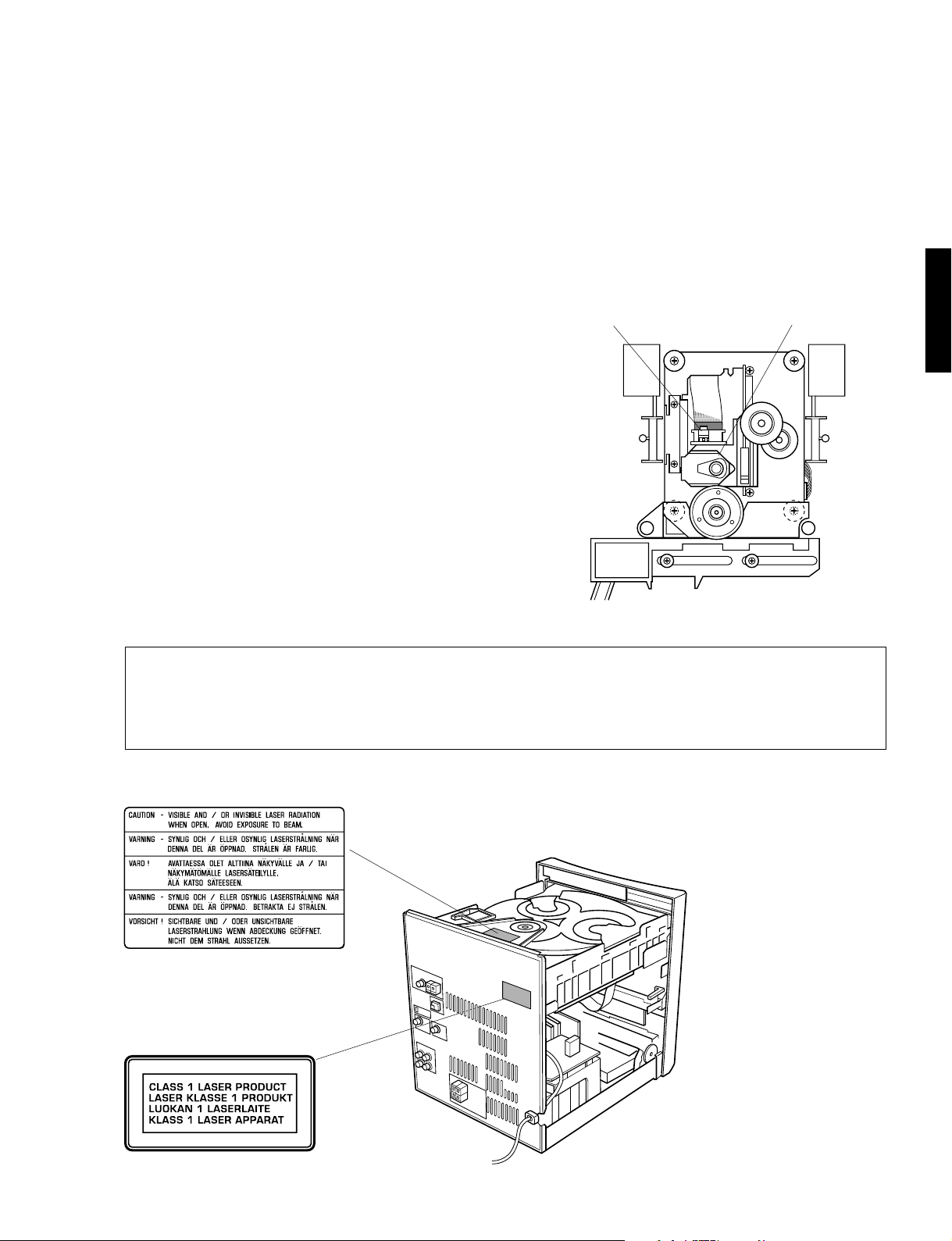
WARNING: Laser Safety
This product contains a laser beam component. This component may emit invisible, as well as visible radiation,
which may cause eye damage. To protect your eyes and skin from laser radiation, the following precautions must
be used during servicing of the unit.
1) When testing and/or repairing any component within the product, keep your eyes and skin more than 30 cm away from
the laser pick-up unit at all times. Do not stare at the laser beam at any time.
2) Do not attempt readjustment, disassembly or repair of the laser pick-up, unless noted elsewhere in this manual.
3) CAUTION : Use of controls, adjustments or performance of procedures other than those specified herein may result in
hazardous radiation exposure.
1
GX-707/GX-707VCD
Laser Emitting conditions:
1) When the Top Cover is removed, and the STANDBY SW is turned to the "ON" position, the laser component will emit
a beam for several seconds to detect if a disc is present. During this time (5-10 sec.) the laser may radiate through the
lens of the laser pick-up unit. Do not attempt any servicing during this period!
If no disc is detected, the laser will stop emitting the beam. When a disc is set, you will not be exposed to any laser
emissions.
2) The laser power level can be adjusted with the VR on the pick-up PWB, however, this level has been set by the factory
prior to shipping from the factory. Do not adjust this laser level control unless instruction is provided elsewhere in this
manual. Adjustment of this control can increase the laser emission level from the device.
GX-707/VCD
Variable resistor
Laser Diode Properties
Material : GaAlAs
Wavelength : 780 nm
Emission duration : Continuous
Laser output : Max. 44.6µW*
ANSI Class : Class 1
* This output is the value measured at a distance of about
200 mm from the objective lens surface on the Optical Pickup Block.
VARO! : AVATTAESSA JA SUOJALUKITUS OHITETTAESSA OLET ALTTIINA NÄKYMÄTTÖMÄLLE
LASER-SÄTEILYLLE. ÄLÄ KATSO SÄTEESEEN.
VARNING! : OSYNLIG LASERSTRÅLNING NÄR DENNA DEL ÄR ÖPPNAD OCH SPÄRREN ÄR URKOPPLAD.
BETRAKTA EJ STRÅLEN.
(Do not turn)
Optical pick-up
B, G, R, L, T models
B, G, R, L, T models
2

GX-707/GX-707VCD
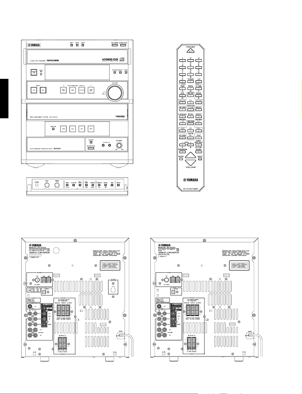
■ GX-707 PANELS
▼ U, C, R, A models
GX-707/VCD
▼ B, G models
3

GX-707/GX-707VCD
▼ U, C models
▼ R model
GX-707/VCD
▼ A model
▼ B, G models
4
GX-707/GX-707VCD
■ GX-707VCD PANELS
GX-707/VCD
▼ R, T models
▼ L model
5

■ SPECIFICATIONS
GX-707/GX-707VCD
■ AMPLIFIER SECTION
Minimum RMS Output Power per Channel
FRONT, 1kHz, 0.9% THD, 6Ω .......................80W + 80W
FRONT, 1kHz, 10% THD, 6Ω ....................100W + 100W
CENTER, 1kHz, 0.9% THD, 6Ω.................................80W
CENTER, 1kHz, 10% THD, 6Ω................................100W
REAR, 1kHz, 0.9% THD, 6Ω......................................25W
REAR, 1kHz, 10% THD, 6Ω.......................................30W
Input Sensitivity/Impedance
AUX/MD ........................................................ 200mV/47kΩ
Spectrum Analyzed Band ............................................. 5 band
(100Hz, 350Hz, 1kHz, 3.5kHz, 10kHz)
■ VIDEO SECTION (GX-707VCD only)
Signal Level ..............................................................1Vp-p/75Ω
■ TUNER SECTION
FM Tuning Range
U, C models.......................................... 87.5 to 107.9MHz
R, T models ........ 87.5 to 108.0MHz/87.50 to 108.00MHz
A, B, G, L models ............................. 87.50 to 108.00MHz
AM Tuning Range
U, C models............................................ 530 to 1,710kHz
R, T models ................. 530 to 1,710kHz/531 to 1,611kHz
A, B, G, L models ................................... 531 to 1,611kHz
FM Usable Sensitivity (75Ω)
30dB S/N Quieting, Mono, 1kHz,
100% mod. R, U, C, L, T models .........1.5µV (14.8dBf)
DIN Mono, S/N 26dB (A, B, G only) ........................1.8µV
■ CD CHANGER SECTION
Type .......................................... 3-Disc Carousel Auto-changer
Signal Readout......................................................Non-contact,
D/A Converter............................................................. 1bit DAC
Filter ........................................8-time oversampling digital filter
Wow & Flutter ....................................................Unmeasurable
3-beam semi-conductor laser pick-up
■ TAPE DECK SECTION
Type ..................................................................... Auto Reverse
4-Track 2-Channel playback/recording stereo Cassette Deck
Heads
REC/PB..................................................... Hard permalloy
Erase................................................... Double Gap Ferrite
Motors
Main ......................................................... DC servo motor
Tray Loading...................................................... DC motor
Wow & Flutter
W.PEAK ................................................................. ±0.19%
W.RMS..................................................................... 0.09%
Frequency Response (–20dB)
Type I/Normal tape........................ 50 to 15,000Hz ± 3dB
Type II/High (CrO2) tape ............... 50 to 16,000Hz ± 3dB
S/N Ratio
NR off.........................................................................58dB
Dolby B NR on........................................................... 66dB
■ CENTER SPEAKER SECTION (NX-C707)
Type ....................................... Full Range Acoustic Sustension
Speakers ...................................... 8cm (3-1/8”) Cone Type X 2
Frequency Range..............................................90Hz to 25kHz
Nominal Input...................................................................100W
Maximum Input ................................................................180W
Impedance ............................................................................ 6Ω
Sensitivity ........................................................ 87dB/2.83V, 1m
Magnetic Shielding Type
■ REAR SPEAKER SECTION (NX-E707)
Type ....................................... Full Range Acoustic Sustension
Speakers ............................................. 8cm (3-1/8”) Cone Type
Frequency Range........................................... 100 to 20,000Hz
Maximum Input ................................................................100W
Impedance .......................................................................... 12Ω
Sensitivity ........................................................ 84dB/2.83V, 1m
Magnetic Shielding Type
■ GENERAL
Power Supply
U, C models............................................... AC120V, 60Hz
A model...................................................... AC240V, 50Hz
B, G, L models........................................... AC230V, 50Hz
R, T models ..................... AC110/120/220/240V, 60/50Hz
Power Consumption........................................................170W
Dimensions (W X H X D)
GX-707/GX-707VCD........................ 280 X 320 X 365mm
NX-GX505........................................ 200 X 320 X 208mm
NX-C707 .......................................... 280 X 100 X 188mm
NX-E707 ............................................. 94 X 117 X 108mm
Weight
GX-707/GX-707VCD........................ 10.5kg (23 lbs. 2 oz)
NX-GX505....................................3.8kg (8 lbs. 6 oz)/each
NX-C707 .............................................. 2.0kg (4 lbs. 6 oz)
NX-E707....................................... 0.7kg (1 lbs. 8 oz)/each
Finish
GX-707/GX-707VCD........................................ Black color
NX-GX505........................................................ Black color
NX-C707 .......................................................... Black color
NX-E707........................................................... Black color
Accessories ............................................ AM loop a ntenn a X 1
(approx. 1.3W when set to the standby mode)
(11” X 12-5/8” X 14-3/8”)
(7-7/8” X 12-5/8” X 8-3/16”)
(11-7/16” X 3-15/16” X 7-3/8”)
(3-11/16” X 4-5/8” X 4-1/4”)
Indoor FM antenna X 1
Remote Control Transmitter X 1
Battery (size “AA”, R06) X 2
Speaker Cord (5m x 3, 10m x 2)
Screws (Rear) X 2
Velcro Strips (Center) X 4
Mounting Brackets (Rear) X 2
* Specifications subject to change without notice.
GX-707/VCD
■ FRONT SPEAKER SECTION (NX-GX505)
Type .............................................................. 3way Bass Reflex
Magnetic Shielding Type
Speakers ............................ 13cm (5-1/8”) Cone Type (Woofer)
5cm (1-15/16”) Cone Type (Tweeter)
2cm (13/16”) Piezo Type (Super Tweeter)
Frequency Range.............................................. 60Hz to 27kHz
Nominal Input ...................................................................100W
Maximum Input ................................................................220W
Impedance ............................................................................ 6Ω
Sensitivity ........................................................ 90dB/2.83V, 1m
Crossover Frequecy ......................................................... 3kHz
* Manufactured under license from Dolby Laboratories Licensing
Corporation. “DOLBY”, “PRO LOGIC”, and the double-D symbol
V are trademarks of Dolby Laboratories Licensing Corporation.
U ......................... U.S.A. model G .................. European model
C ................... Canadian model R ...................... General model
A .................. Australian model L.................. Singapore model
B ........................ British model T.......................... China model
6
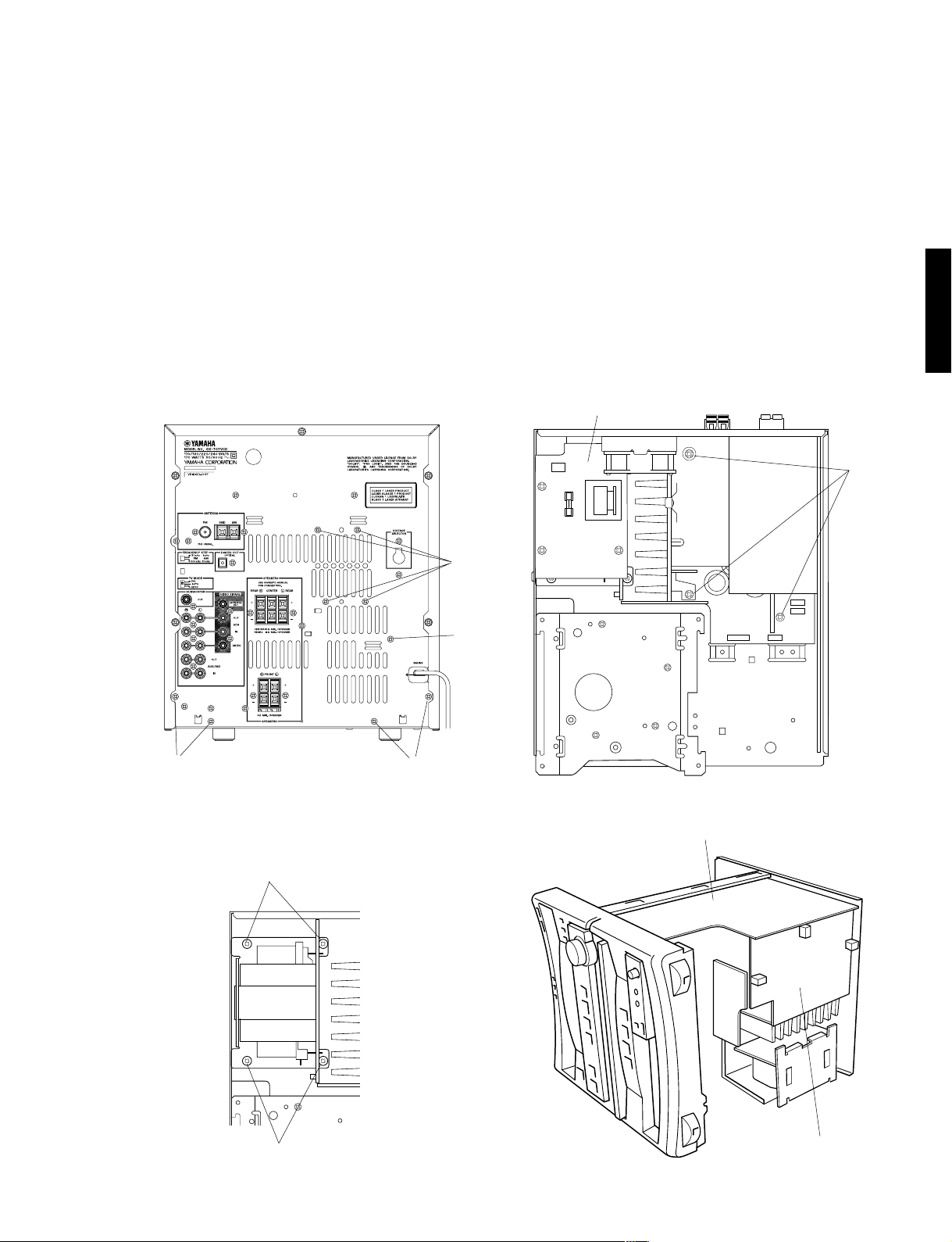
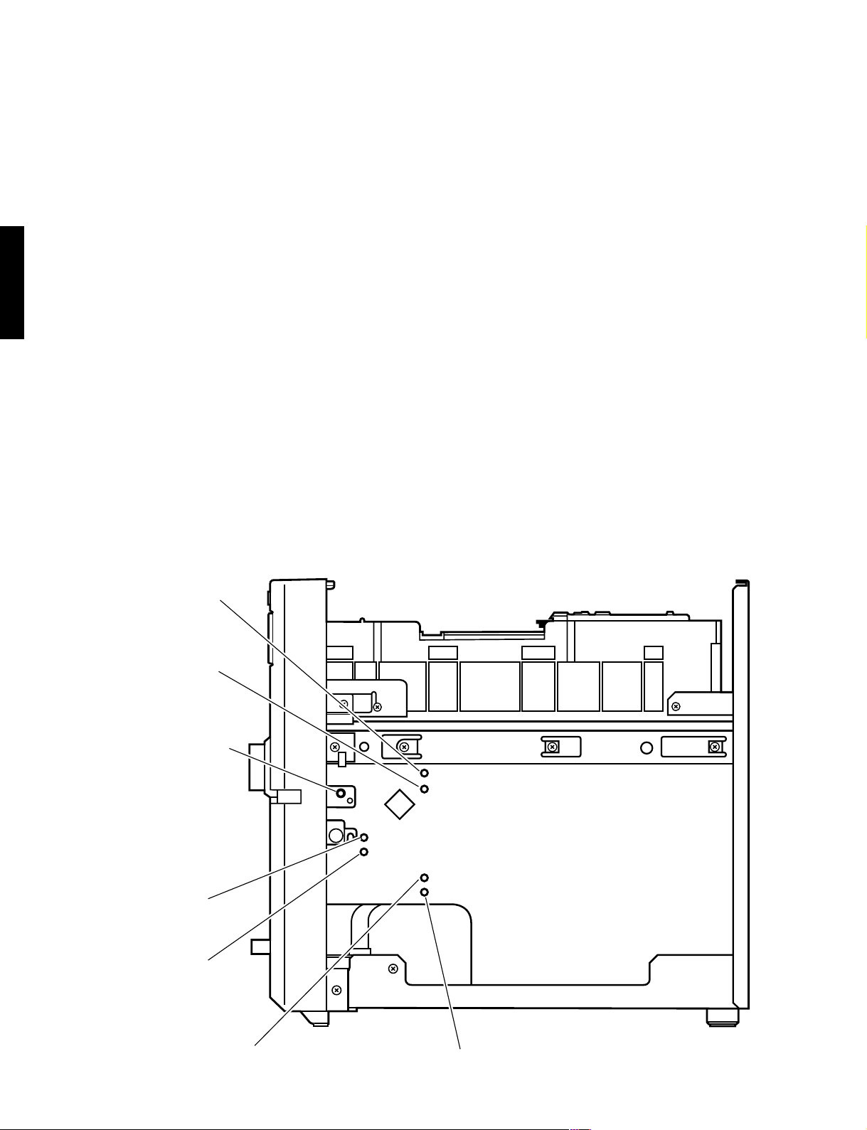
GX-707/GX-707VCD
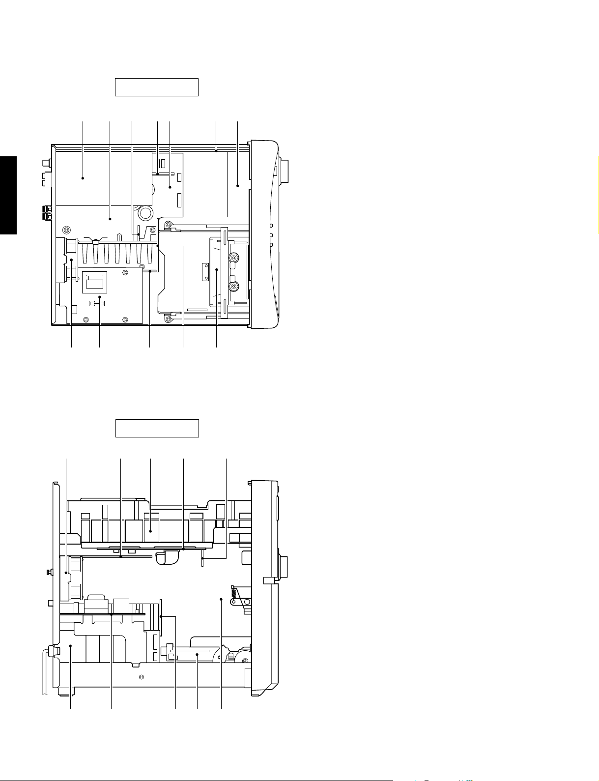
■ INTERNAL VIEW
q w
GX-707/VCD
Top side
e
(with CD/VCD Mechanical Unit removed)
t yr
!1
u
!2o !0i
q TUNER P.C.B.
w EFFECT P.C.B. (2)
e MAIN P.C.B. (5)
r EFFECT P.C.B. (1)
t MAIN P.C.B. (1)
y INPUT P.C.B. (1)
u OPERATION P.C.B. (3)
(GX-707VCD only)
i FAN
o MAIN P.C.B. (2)
!0 MAIN P.C.B. (3)
!1 MAIN P.C.B. (6)
!2 DECK MECHANICAL UNIT
!3 GX-707 CD MECHANICAL UNIT
GX-707VCD VCD MECHANICAL UNIT
!4 GX-707 CD P.C.B.
GX-707VCD VCD P.C.B.
!5 VCD MODULE (GX-707VCD only)
Left side
!3i q
!4 !5
!0 !1
7
o
y!2

GX-707/GX-707VCD
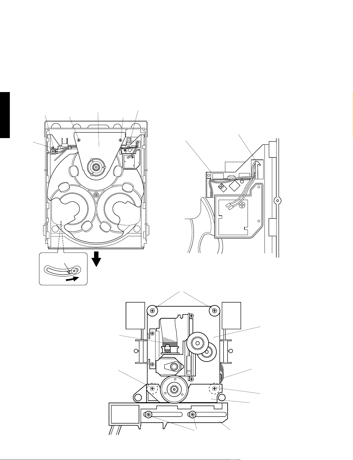
■ DISASSEMBLY PROCEDURES (Remove parts in the order as numbered.)
1. Removal of Top Cover
Remove 11 screws ( q ) in Fig. 1.
Top Cover
q
q
2. Removal of CD/VCD Mechanical Unit
a. Disconnect the power cord from the AC outlet.
b. Push the Friction Arm ( the bottom side of the CD/
VCD Mechanical Unit ) with a finger as shown in Fig.
2.
c. Pull the Tray forward approx. 5cm ( 2" ) and remove
the CD Lid in Fig. 2.
d. Push the Tray back to the original, closed position.
e. Disconnect the Flat Connecting Cables ( CB10 )
CD/VCD P.C.B.
CB12 and CB9 )
and remove 3 connectors ( CB11 ,
on the CD/VCD P.C.B.
on the
in Fig. 2
f. Remove 4 screws ( w ) and then remove the CD
Mechanical Unit in Fig. 1.
3. Removal of Panel Unit
a. Rotate the Loading Gear, then open the Tray and
remove the Cassette Lid in Fig. 2.
b. Push the Tray back to the original, closed position.
c. Disconnect the flat connecting cables ( CB10, CB13
and CB11 ) on the INPUT P.C.B. and remove a
connector ( CB805 ) in Fig. 2.
d. Remove 5 screws ( e ) and 2 screws ( r ), and then
remove the Panel Unit in Fig. 1 and Fig. 2.
Friction
Arm
q
q
CD/VCD Mechanical Unit
w
e
w
r
e
e
Panel Unit
Fig. 1
4. Removal of Deck Mechanical Unit
a. Remove 4 screws ( t ) and then remove the Deck
Mechanical Unit in Fig. 3.
b. Remove 3 connectors ( W2, W3 and W4 ) in Fig. 3.
q
GX-707/VCD
w
CB11
r
CD/VCD P.C.B.
CB12
(VCD only)
CB9
(VCD only)
INPUT P.C.B.
CB11
FRONT
CB10
CB13
CB10
Loading Gear
CD Lid
Cassette Lid
Fig. 2
CB805
W2
t
t
Deck Mechanical Unit
W4
W3
t
t
Fig. 3
8

GX-707/GX-707VCD
5. Operation Check of CD/VCD P.C.B.
a. Remove the CD Mechanical Unit.
b. Remove 5 screws ( y ) and then remove the CD/VCD P.C.B. in Fig. 4.
c. Place blocks (at 3 locations) to hold the CD Mechanical Unit horizontally as
shown in the Fig. 5.
d. Connect the Flat Connecting Cable ( CB10 ) and 3 connectors ( CB11,
CB12 and CB9 ) in Fig. 4 and Fig. 5.
e. Fit insulating material (thick paper, etc.)to prevent the chassis from
contacting the CD/VCD P.C.B.
f. Connect the power plug and turn on the Power Switch.
GX-707/VCD
CD/VCD P.C.B.
y
CB11
CB12 (VCD only)
CB9
y
y
CB10
y
VCD Module
(GX-707VCD only)
y
Fig. 4
CD/VCD P.C.B.
Block
Block
Block
Fig. 5
9
GX-707/GX-707VCD
6. Operation Check of Main P.C.B. (1)
a. Remove the CD Mechanical Unit.
b. Remove the Panel Unit.
c. Remove the Deck Mechanical Unit.
d. Remove 4 screws ( u ) and then remove the Fan in Fig. 6.
e. Remove 5 screws ( i ) in Fig. 6.
f. Remove 1 screw ( o ) and then remove the P.C.B. Main (2) in Fig. 7.
g. Remove 3 screws ( !0 ) in Fig. 7.
h. Remove 4 screws ( !1 ) and then remove the Power Transformer in Fig. 8.
i. Place the main unit on its left side (viewed from the front) and remove the Bottom Cover in Fig. 9.
j. Install the Panel unit to the main unit in Fig. 9.
k. Connect the flat connecting cables ( CB10, CB13 and CB11 ) and remove a connector ( CB805 ) in Fig. 2.
l. Connect the power plug and turn on the Power Switch.
CAUTION
When the power to this equipment is turned on with the CD/VCD Mechanical Unit disconnected, the capacitor C255(4700/
16) of the Main P.C.B. (CD/VCD power supply section) is charged. Connecting the CD/VCD P.C.B. in this state may cause
damage to its IC. Therefore, when installing the CD/VCD Mechanical Unit, be sure to discharge the capacitor C255(4700/
16) of the Main P.C.B. before making connections. (To discharge it, short the W201 terminal +B and GND with a
resistor(270Ω 1W).)
Main P.C.B. (2)
GX-707/VCD
!0
u
o
i
ii
Fig. 6
!1
Fig. 7
Input P.C.B.
!1
Fig. 8
Main P.C.B. (1)
Fig. 9
10
GX-707/GX-707VCD
7. Removal of Tray & Traverse Unit
a. Remove 2 screws ( !2 ) and then remove the Clamper Bracket in Fig. 10.
b. Remove 1 screw ( !3 ) and then remove the Lever Switch in Fig. 10.
c. Disconnect the Flat Connecting Cable ( 9P ) in Fig. 10.
d. Push the Friction Arm ( the bottom side of the CD Mechanical Unit ) with a screwdriver or the like and pull out the Tray
forward as in Fig. 10.
e. Unhook 1 Tray hook in Fig. 11 and pull out the Tray.
f. Remove 4 screws ( !4 and !5 ) in Fig. 12.
g. Disconnect the Flat Connecting Cable ( 16P ) and connectors ( 6P ).
h. Take out the Traverse Unit with the Slider Cam and the TU Holder in Fig. 12.
i. Remove 2 screws ( !6 ) and then remove the TU Holder in Fig. 12.
Lever Switch
(OPEN/CLOSE)
GX-707/VCD
!3
Friction
Arm
Clamp Bracket
!2
CN3(9P)
!2
Tray
Fig. 10
Hook
Fig. 11
11
16P
!6
!5
Traverse Unit
6P
!6
TU Holder
!4
Slider Cam
Fig. 12

GX-707/GX-707VCD
8. Removal of Pick-up Head
a. Remove a washer ( !7 ) and then remove the Driving
Gear in Fig. 13.
b. Remove 2 screws ( !8 ), pull out the Guide Rod and
then remove the Pick-up Head in Fig. 13.
Guide Rod
!8
Driving Gear
!7
9. Removal of Cassette Mechanism
Remove 4 screws ( !9 ) and then pull out the Cassette
Mechanism in Fig. 14.
10. Removal of Main Motor
Remove 2 screws ( @0 ) in Fig. 14.
11. Removal of Pinch Roller
Detach the hook and then remove the Pinch Roller
in Fig. 15.
12. Removal of Head Ass’y
a. Remove 1 screw ( @1 ) and then remove the Relay
P.C.B. in Fig. 15.
b. Remove 2 screws ( @2 ) and then remove the Head
Ass’y in Fig. 15.
* Perform the azimuth adjustment after installing the
Head Ass’y.
!9
!9
GX-707/VCD
Pick-up Head
!8
Fig. 13
● Check that the disc table height is as specified below.
19.4 ± 0.2 mm
Fig. A
!9
Head Ass'y
Hook
@0
!9
@0
Fig. 14
Hook
Pinch Roller (L)
@1@2 @2
Pinch Roller (R)
Fig. 15
12

GX-707/GX-707VCD
● DIMENSIONS
12
(1/2")
● NX-GX505● GX-707/GX-707VCD
● NX-E707
100
GX-707/VCD
(3-15/16")
172 (6-3/4")
■ VOLUME RANGE
280 (11")
339 (13-3/8")
365 (14-3/8")
14
(9/16")
320 (12-5/8")
● NX-C707
200 (7—7/8")
280 (11")
320 (12—15/8")
(1/16")
192 (7—9/16")15.8
207.8 (8—3/16")
100 (3—15/16")
1.4 (1/16")
188 (7—3/8")
94 (3—11/16") 87 (3—7/16")
108 (4—1/4")
117 (4—5/8")
Unit : mm (inch)
DISPLAY
VOL MIN
VOL 01
VOL 02
VOL 03
VOL 04
VOL 05
VOL 06
VOL 07
VOL 08
VOL 09
dB
– ∞
–79
–73
–68
–64
–61
–59
–58
–57
–56
DISPLAY
VOL 10
VOL 11
○○○○○○○○
VOL 54
VOL 55
NOTE) When VOLUME is at minimum, AMP MUTE is on.
■ SYSTEM CONTROL CHECK
q FUNCTION AUX/MD is selected
CD PLAY KEY ON (remote control transmitter)
↓
w FUNCTION → CD ?
13
DISC No. display on?
yes
↓
CHECK OK
no
dB
–55
–54
1dB step
–11
–10
DISPLAY
VOL 56
VOL 57
VOL 58
VOL 59
VOL 60
VOL 61
VOL 62
VOL 63
VOL 64
VOL MAX
dB
–9
–8
–7
–6
–5
–4
–3
–2
–1
0
In case that CD doesn’t play : [RECEIVER → CD]
(SYSCK, CDCE, SYSO) NG
In case that DISPLAY doesn’t change : [CD → RECEIVER]
(SYSI) NG
SYSCK: Pin 20 of IC8
CDCE: Pin 25 of IC8
SYSO: Pin 21 of IC8
SYSI: Pin 22 of IC8

GX-707/GX-707VCD
■ TEST MODE
To facilitate inspection, measurement and location of any faulty point, 6 types of built-in Test Modes are provided,
one for each section.
• System Test Mode : Test mode for the system section. It is also used when entering the test mode for each section.
• Receiver Test Mode : Test mode for the receiver section
• Tape Test Mode : Test mode for the deck section
• CD Test Mode : Test mode for the CD section
• MD Test Mode : Test mode for the MD section (unused for this unit)
• All Function Test Mode : Test mode for all functions
■ SYSTEM TEST MODE
This test mode is used for the system section. Also, this mode must be executed first when entering the test mode
for each section.
Starting Procedure
In the STANDBY mode, press the STANDBY/ON button while pressing the RANDOM button and the PLAY/
PAUSE(CD) button simultaneously. Once the SYSTEM TEST MODE is set, causal factors for the previous power
off appear on the FL display.
GX-707/VCD
Causal factors for power off at starting
Display Description
<Key Operate Power off by button operation
<Off Timer Power off by Off Timer setting
<Sleep Timer Power off by Sleep Timer function
<Auto Off Power off by Auto Power Off function
<I-Protect Power off by detection of an abnormal current value
<V-Protect Power off by detection of an abnormal voltage value
<Temp Over Power off by detection of an abnormal temperature value
<AC Cut Power off by AC power cut
<?? Unknown
Operation Procedure (Selection/finalizing of TEST MODE for each section)
1) Select the TEST MODE by the section name, pressing the wINPUT (up) or q INPUT (down) button.
Display Description Ref. page
<Key Operate Causal factors for power off are displayed. 14
(This state is available immediately after starting.)
Test RECEIVER RECEIVER TEST MODE 15
Test TAPE TAPE TEST MODE 16
Test CD CD TEST MODE 17
Test MD MD TEST MODE (Unused for this unit) —
Test All Func ALL FUNCTION TEST MODE 18
Escape Test The test mode is canceled. —
2) Pressing the MUSIC button will shift the mode to the selected test mode.
For the details of the selected test mode, refer to the Ref. page in the above step 1).
14
GX-707/GX-707VCD
■ RECEIVER TEST MODE
When the RECEIVER TEST MODE is set through the SYSTEM TEST MODE, “01 G.E.TEST” appears on the FL display.
(01 is the test program No.)
Test programs from 01 to 25 are incorporated in RECEIVER TEST MODE.
Operation Procedure (Selection/execution of Test Program)
1) Select the test program by pressing the rTAPE (up) or eTAPE (down) button.
2) Pressing the STANDBY/ON button will execute the selected test program.
3) Repeat selection/execution of the test program as necessary.
No. & DISPLAY
01 G , E , TEST
GX-707/VCD
02 FL + CLEAR
03 FL FULL
04 APO - ON/OFF
05 RDS - OFF/ON
06 A , PS - ON/OFF
07 A , M , - RDS/ALL
08 CT > C - ON/OFF
09 L > CT - ON/OFF
10 PSR2 - ON/OFF
11 RTBL - ON/OFF
12 SEC - OFF/ON
13 Temp
14 PEAK - ON/OFF
15 AMPC - OFF/ON
16 CDCH - ON/OFF
17 REM CODE
18 L , EN - ON/OFF
19 ALL CH >
20 RDS E / F
21 SUR TEST
22 KEYC - OFF/ON
23 AM - IF
24 CANCEL
25 DEST
FUNCTION
Equalizer check mode
FL display full lighting,
RAM CLEAR
FL display full lighting
Do not use No. 04 to 12 functions as they are not for servicing.
Temperature Detection
& Fan Control
Do not use No. 14 to 23 functions as they are not for servicing.
Used to cancel the test program.
(The normal operating mode is restored when the STANDBY/ON button is pressed.)
Destination display mode
Used to check EQ.
Pressing the STANDBY/ON button will set the Equalizer Test mode.
For the details, refer to page 16.
Used for lighting of all display segments and clearing of RAM. (Note that
the user memory will be cleared.)
At the first pressing of the STANDBY/ON button, all display segments light up
and at the second pressing, MEMORY and M-CLEAR light up for 2 seconds
and RAM of CPU is initialized. (The normal operating mode is restored.)
(Presetting of the tuner becomes the manufacturer preset state.)
Used to check lighting of all display segments.
At the first pressing of the STANDBY/ON button, all display segments light up and at the
second pressing, this mode is canceled. (The normal operating mode is restored.)
Used to check the fan.
Pressing the STANDBY/ON button sets the fan test mode.
(The detected temperature and the fan control level are displayed. For the
details, refer to page 16.)
PURPOSE & OPERATION
15
GX-707/GX-707VCD
Equalizer test mode (Test program No. 01)
When the equalizer test mode is set, “GEQ - xxx” is displayed. “xxx” represents the 3 band value of GEQ.
It is possible to set the GEQ value directly, using the buttons on the remote control unit.
Example : To obtain flat
GEQ - 6 6 6
Low tone Intermediate tone High tone
Displayed value 0 123456789ABC
Gain (dB) -12 -10 -8 -6 -4 -2 0 +2 +4 +6 +8 +10 +12
Operation Procedure
• To set a value for each band
[ 0 ] to [ 9 ], [ A(TIME) ], [ B(PROG) ], [ C(R.TIME)]
• To set all bands to Min (-12dB)
[ D(EDIT) ]
• To set all bands to Max (+12dB)
[ E(+10) ]
• To cancel this test mode, press the STANDBY/ON button. (The normal operating mode will be restored.)
Fan test mode (Test program No. 13)
When the fan test mode is set, “Temp xx y” is displayed. “xx” represents the detected temperature of the Power
IC and “y” the value of the fan control level. It is possible to run the fan regardless of the detected temperature.
Operation Procedure
Pressing the wINPUT (up) or qINPUT (down) button causes the fan control level value to change. To cancel this
test mode, press the STANDBY/ON button. (The normal operating mode will be restored.)
● FACTORY PRESET
BAND
FM (MHz)
AM (kHz)
NOTE 1) PRESET PAGE ............................................ A : FM B : AM C : FM D : AM E : FM
U, C, R, T (100k/10k)
A, B, G, L, R, T (50k/9k)
U, C, R, T (100k/10k)
A, B, G, L, R, T (50k/9k)
MARKETS
1
98.1
98.10
630
630
2
95.1
95.10
1080
1080
3
87.5
87.50
1400
1404
PRESET No.
4
101.5
101.50
530
531
5
107.9
108.00
1710
1611
6
88.1
88.10
900
900
7
106.1
106.10
1350
1350
8
107.9
107.90
1440
1440
GX-707/VCD
CAUTION : When executing Test program No. 2 RAM CLEAR, be sure to write down the preset memory contents of the
tuner, using a table like the one shown below. Execution of RAM CLEAR will set the memory contents of the
tuner back to the factory preset state which means that all the memories preset by the user will be erased.
Preset group
A
B
C
D
E
P1 P2 P3 P4 P5 P6 P7 P8
■ TAPE TEST MODE
When the TAPE TEST MODE is set through the SYSTEM TEST MODE, “Tape Test XXXX” appears on the FL display.
(XXXX is the counter value.)
The operating condition of the deck section will be as follows.
• When the reverse mode is set to “endless”, the number of playback repetition becomes unlimited.
(It is set to “8” times in the normal operating mode.)
• When in the REC mode, AUX/MD is used automatically for the input source.
16

GX-707/GX-707VCD
■ CD TEST MODE
When the CD TEST MODE is set through the SYSTEM TEST MODE, “00 TM1 0: 00” appears on the FL display.
The CD TEST MODE is enabled. Each button operates as follows for each mode. The MODE No. is increased by
pushing
"+10" button.
Button
" 0 "
" 1 "
" 2 "
GX-707/VCD
" 3 "
" 4 "
" 5 "
" 6 "
" 7 "
" 8 "
" 9 "
Button
" 0 "
" 1 "
" 2 "
" 3 "
" 4 "
" 5 "
" 6 "
" 7 "
" 8 "
" 9 "
MODE 1 MODE 2 MODE 3
Open/close the tray Focus search Cancel adjust pass *2
Clamp up/down Play (PLL) Auto adjustment mode 1 *1
Tracking Offset, Focus Offset,
Focus Gain
DISC change Play (without PLL) Auto adjustment mode 2 *1
Tracking Balance, Tracking Gain
Mechanism home process Focus on, Tracking off, Feed off Auto adjustment mode 3 *1
Focus Gain, Tracking Gain,
Focus Balance
Jump to test mode 4 +10 track kick Read and display the servo
coefficient
Tray close, Clamp down –10 track kick Displayed servo coefficient
address up
— +1 track kick Displayed servo coefficient
address down
Enter normal operation –1 track kick Displayed servo coefficient
(without mecha. INIT.) increment
Enter normal operation +30 track kick Displayed servo coefficient
decrement
Start TEST REPEAT –30 track kick Send the displayed servo
(Do not use this function as coefficient *2
it is not for servicing.)
MODE 4 MODE 5 (GX-707VCD only)
Feed forward (outer direction) CD-ROM module load
Feed backward (inner direction) CD-G module load
Rotate the disc motor Decoder play command
Retard the disc motor Decoder pause command
port TBLL ← Low, Decoder abort command
port TBLR ← High
port TSLW High/Low alternate Decoder soft reset
Tray port control (open/close) Decoder hard reset
Line mute on/off —
——
Jump to Test mode 1 —
*1 “Adj-” lights during the
adjustment and disappears at
the end of the adjustment.
*2 When the mode is reset to the
normal operating mode after the
servo coefficients are reset by
this operation, auto adjustment
is not available unless the auto
adjustment pass function is
cancelled.
The following buttons test mode functions do not depend on the test mode No.
OPEN/CLOSE
DISC CHANGE
a (STOP)
w / d
(PLAY/PAUSE)
y
t
DISC 1
[VCD Module condition check]
If the VCD module is in a good condition, the blue background appears on the monitor screen when in the CD test mode.
If the blue background does not appear, the possibility is that the VCD module has failed.
NOTE: None of the components of the VCD module can be supplied separately. Only a VCD module unit (VZ150200) is available.
Open/close the tray
Clamp up/down
Controls for the tray, the disc table and clamping stop. STANDBY command for the servo system.
Play (PLL)
Feed forward (outer direction)
Feed backward (inner direction)
Tray close, clamper down
17

GX-707/GX-707VCD
■ ALL FUNCTION TEST MODE
When ALL FUNCTION TEST MODE is set through SYSTEM TEST MODE, “AUX/MD” appears on the FL display.
The operation condition in this mode will be as follows.
• AUX/MD is used as the input source of the receiver section, which is then set to the Dolby Pro Logic mode (GX707VCD only).
• When a CD is loaded, Full Repeat Play is executed automatically for it.
• When a cassette tape is loaded, Endless Rec Play is executed by the cassette deck automatically.
■ CD ERROR MESSAGES
The error message can be obtained on the display by pushing the STOP and TIME buttons simultaneously when the
CD has stopped (sometimes with the tray open) by a defect.
GX-707/VCD
INDICATION
E-10
E-20
E-30
E-70
E-11
E-21
E-31
E-73
E-04
E-14
E-35
E-06
E-47
E-57
E-77
E-18
E-28
E-38
E-48
E-68
E-AA
E-AB
E-AC
E-AD
E-AE
E-AF
MN ERR
STATE
PLAY
SCAN
PAUSE
SEARCH
PLAY
SCAN
PAUSE
SEARCH
LOAD, SEARCH
LOAD, SEARCH
SEARCH, PLAY, PAUSE
SEARCH
STOP
LOAD, EJECT, CHANGE
PLAY
SCAN
PAUSE
SEARCH
LOAD, DISC CHANGE
CONTENTS OF ERROR
CD fails in the disc data reading after the state shift.
CD fails in the disc data reading.
CD fails in the TOC data reading.
Tracking servo is not effective at the disc motor servo PLL.
Disc motor servo PLL is not effective.
CD fails in focus search.
CD fails in escaping from the lead-in area.
The inner limit switch does not operate at the feed inner control.
CD fails in recovery from the focus out.
Clamp down switch does not operate at the clamp down control.
Clamp up switch does not operate at the clamp up control.
Close switch does not operate at the tray close control.
Open switch does not operate at the tray open control.
CD fails in the table control.
CD fails in the mecha. home process.
MN35511 does not give response of SENSE with resetting by the units
microcomputer.
When "MECHA ER" message appears on the display;
Possible symptoms are, the clamp does not move up or down, the table does not turn, mecha. sensor switch malfunctions, etc.
The normal operation may be restored by tuning off the power once and then on again. If it does not work in this way, disassemble the CD mechanical unit and investigate the cause of the failure.
18
GX-707/GX-707VCD
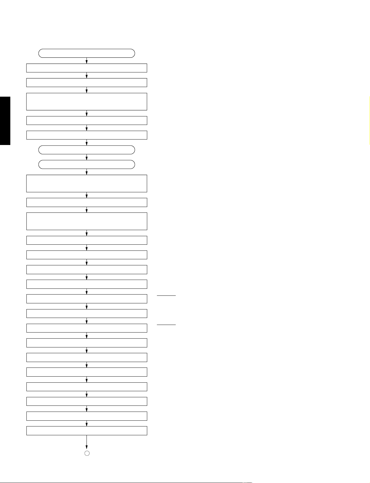
■ CD STANDARD OPERATION CHART
Forced feed return operation.
Tracking Offset auto ADJ. (only POWER ON)
GX-707/VCD
Focus Offset auto ADJ. (only POWER ON)
Press PLAY key or push the tray.
Disc mechanism unit clamped up.
Feed inward switch sensing.
Press OPEN/CLOSE key.
Clamp down operation.
Disc table reset.
Tray open.
Load a disc in “DISC 1”.
Tray closed.
Table rotate.
Disc sensing.
“OPEN” appears in the TIME indicator.
“TRV” signal is output until detection of LIMIT switch.
DISC “1” is turned to DM clamp position.
Laser ON.
Disc scan.
FOCUS Gain rough ADJ.
FOCUS Search operation.
FOCUS LOCK servo ON.
Spindle motor accelerated.
TRACKING servo ON.
Disc servo ON
VCO lock.
Tracking Gain rough ADJ.
Tracking Balance ADJ. (only Tray OPEN/CLOSE)
FOCUS BALANCE ADJ.
FOCUS GAIN ADJ.
LDON = “H” (IC5, 40 pin)
FLOCK = “H” → “L” (IC8, 8 pin)
TLOCK = “H” → “L” (IC8, 11 pin)
19
TRACKING GAIN ADJ.
A
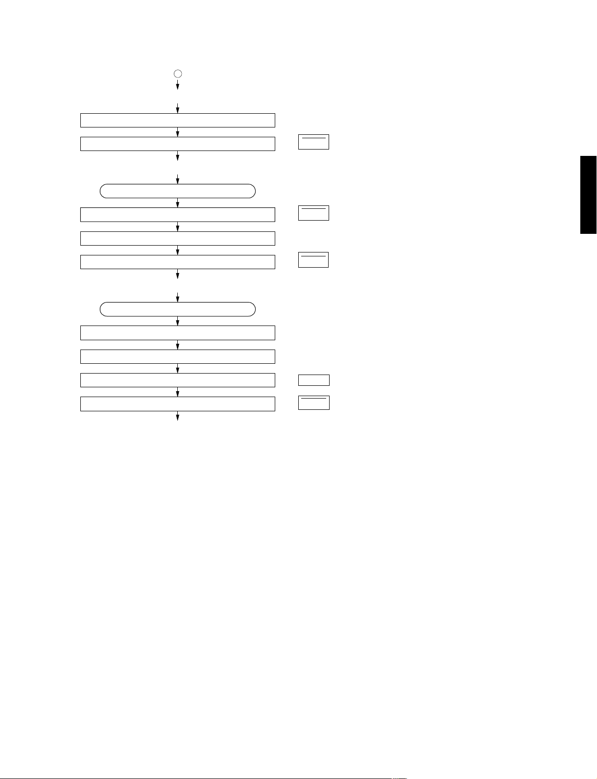
GX-707/GX-707VCD
A
* TOC READ
After searching the beginning, MUTE is cancelled.
Set to SEARCH by means of Y, T key.
After searching the beginning, MUTE is cancelled.
* ~ Data fetch cycle ~
TRACK No. “1” is searched.
~ PLAY ~
MUTE ON.
TRACK search.
~ PLAY ~
Press the STOP key.
MUTE ON.
Spindle motor stop.
Laser OFF.
: MUTE = “L” → “H”, “0:00” appears in the time indicator.
(IC8, 64 pin)
: MUTE = “H” → “L”
: MUTE = “L” → “H”, “0:00” appears in the time indicator.
: LDON = “H” → “L” (IC5, 40 pin)
GX-707/VCD
Forced feed return.
~ STOP ~
: FLSW = “L” (IC8, 26 pin)
20
GX-707/GX-707VCD
■ ADJUSTMENTS (DECK SECTION ONLY)
1. Before adjustment
● Since head magnetization, dust accumulations, etc.
are likely to introduce error in the various characteristics, it is very important that the heads are properly
demagnetized and cleaned.
● Make adjustments of mechanical system, playback
system and recording system in that order.
● Except for azimuth adjustment, adjust in the forward
direction.
●
Adjust using the TAPE TEST MODE (shown on page 16).
2. Instruments required
● Audio frequency oscillator
GX-707/VCD
● ACVM or dual channel (ACVM)
● DCVM
● Wow/flutter meter
● Oscilloscope
● Frequency counter
● Torque meter
TW-2111A (TX911580) ... Take up/back tension (FWD)
TW-2121A (TX911570) .... Take up/back tension (RVS)
CT-160L (TX911120) .................................. FF/REW
3. Test tape required
●
MTT-111N (TX911650) ........................... No rmal speed
● MTT-114N (TX911680) ................................ Azimuth
● MTT-212N (TX911660) ......................Playback level
● MTT-256 (TX911300)................ Playback frequency
response (Normal)
● MTT-356 (TX911310)................ Playback frequency
● Reference tape
Type
I/Normal (LH).......... TDK AC225 (VU167200)
Type
II/High (CrO2) ......... TDK AC514 (VU167300)
response (CrO
2)
● Test point
REC LEVEL ADJ.
REC LEVEL ADJ.
TAPE SPEED ADJ.
PB LEVEL ADJ.
PB LEVEL ADJ.
(
(
Lch
(
Rch
(
Lch
Rch
)
)
VR7
VR6
VR5
IC6
VR4
VR1
VR3
VR2
)
)
21
BIAS ADJ. (Lch
)
BIAS ADJ. (Rch
)
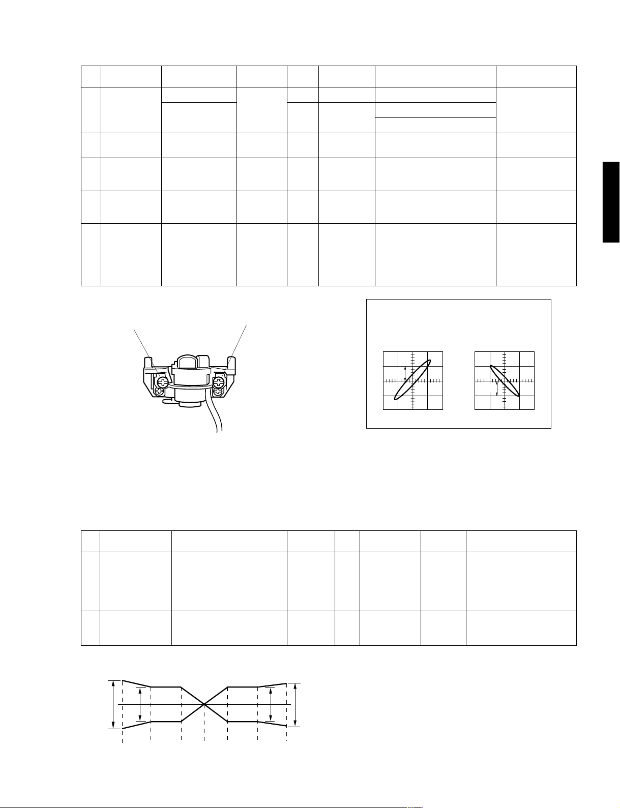
“MECHANICAL ADJUSTMENT”
Item to be
Step
Check each
1
Adjusted
torque
Check FF, REW
2
take up time
Azimuth
3
Tape Speed
4
Wow/Flutter
5
Tape
CT-160L (FF, REW)
TW-2111A (FWD)
TW-2121A (RVS)
AC-514 (C-60)
MTT-114N
10kHz, –10dB
MTT-111N
3kHz, –10dB
MTT-111N
3kHz, –10dB
Instrument
required
Torque
meter
ACVM
Oscilloscope
Frequency
counter
Wow/flutter
meter
Mode
FF REW
PLAY
FF REW
PLAY
PLAY
PLAY
Adjustment
part
Azimuth
adjustment
screw. (Fig. A)
VR7
GX-707/GX-707VCD
Rating
FF, REW torque : within 70—160g/cm.
Take up torque : 30—60g/cm.
Back tension : 1.5—6g/cm.
80 to 120 seconds.
Playback output of L and R is maximum and phase difference should
be minimum both directions. (Fig. B)
3000Hz ± 15Hz
Less than 0.19% (WRMS)
After the adjustment
make sure to apply
screw lock paint.
Perform adjustment at
the center of the test
tape, if possible.
Confirm at center of
the test tape, if possible.
Remarks
GX-707/VCD
Azimuth
adjustment
screw. (FORWARD)
Azimuth
adjustment
screw. (REVERSE)
Fig. A
“ELECTRICAL ADJUSTMENT”
● Use 560 mV (250 nwb/m) for 0 dB as the standard level of the unit.
0dB = 250 nwb/m (315 Hz) = – 7 dBV (Rec out level)
< Playback section >
Step
1
Item to be
Adjusted
Playback
level (315Hz)
MTT-212N
315Hz,
250nwb/m
Tape
Instrument
required
ACVM
Mode
PLAY
Points of
measurement
REC OUT
Rec out L : ch 1
Rec out R : ch 2
DC input, X-Y (Resurge) mode
OK
0.2V
Fig. B
Adjustment
parts
VR4 (L ch)
VR1 (R ch)
NG
0.2V
Rating
– 7 dBV ± 0.3 dBV
Confirmation of
playback frequency
2
response
Test tape for frequency check.
3180µs + 120µs (LH) (MTT-256)
3180µs+70µs (CrO2) (MTT-356)
● PLAYBACK FREQUENCY RESPONSE
± 3dB
± 4dB
1k
± 3dB
3k 10kHz31525050 12.5kHz
ACVM
Oscilloscope
± 3.5dB
Fig. C
PLAY
REC OUT
Check that the 10kHz playback
level is within 0 ± 3 dB of the
1kHz playback level. (Fig. C)
22
GX-707/GX-707VCD
< Recording section >
Item to be
Step
Adjusted
Recording
1
level
Recording
2
bias
(Total
frequency
response)
GX-707/VCD
Confirmation
3
of recorded
level
Tape
AC-514
High
(CrO2)
AC-514
High
(CrO2)
AC-225
Normal
(LH)
AC-514
High
(CrO2)
Instrument
required
ACVM
Audio
frequency
oscillator
ACVM
Audio
frequency
oscillator
ACVM
Audio
frequency
oscillator
Mode
REC
PLAY
REC
PLAY
REC
PLAY
Measurement
conditions
Input 1 kHz Signal to
AUX IN from Audio
Frequency Oscillator.
Adjust output level of
Audio Frequency Oscillator so that the
voltage of REC OUT
becomes – 27 dBV.
Input 12.5 kHz Signal to AUX IN from
Audio Frequency Oscillator.
Adjust output level of
Audio Frequency Oscillator so that the
voltage of REC OUT
becomes – 27 dBV.
Points of
measurement
REC OUT
REC OUT
REC OUT
Adjustment
parts
VR6 (L ch)
VR5 (R ch)
VR3 (L ch)
VR2 (R ch)
Rating
Adjust for equal record and
playback levels.
(– 27 dBV ± 0.3 dBV)
Adjust for equal record and
playback levels.
(– 27 dBV ± 0.3 dBV)
Adjust for equal record and
playback levels. (Fig. D)
Perform record bias adjustment of High (CrO2) tape
again, if the rating was not
satisfied.
Confirm recorded level rating as in step 1 When recorded level rating is improper, go back to step 1
and also carry out adjustments in step 2 again.
● TOTAL FREQUENCY RESPONSE ( – 27 dBV)
Dolby NR B & OFF
Type I (Normal)/Type II (High)
± 4dB
± 5dB
1k
± 3dB
3k 10kHz31525050 12.5kHz
± 5dB
Fig. D
23
0
2
3
4
5
6
7
8
9
■ IC DATA
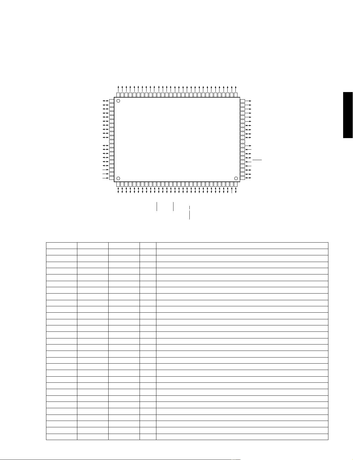
IC8 : M38199EF [CD/VCD P.C.B.]
8 bit
µ-COM (CD CPU)
P90/SEG16
P91/SEG17
8079787776757473727170696867666564636261605958575655545352
VCC
VEE
AVSS
VREF
81
82
83
84
85
86
87
88
89
90
91
92
93
94
95
96
97
98
99
100
123456789
P87/SEG15
P86/SEG14
P85/SEG13
P84/SEG12
P83/SEG11
P82/SEG10
P81/SEG9
P80/SEG8
PA7/SEG7
PA6/SEG6
PA5/SEG5
PA4/SEG4
PA3/SEG3
PA2/SEG2
PA1/SEG1
PA0/SEG0
P92/SEG18
P93/SEG19
P94/SEG20
P95/SEG21
P96/SEG22
P97/SEG23
P30/SEG24
P31/SEG25
P32/SEG26
P33/SEG27
P34/SEG28
P35/SEG29
P36/SEG30
P37/SEG31
P00/SEG32/DIG
P01/SEG33/DIG1
P02/SEG34/DIG
P03/SEG35/DIG
P04/SEG36/DIG
101112131415161718192021222324252627282930
P05/SEG37/DIG
P06/SEG38/DIG
P07/SEG39/DIG
P10/SEG40/DIG
P11/SEG41/DIG
P12/DIG10
P13/DIG11
P14/DIG12
P15/DIG13
51
50
49
48
47
46
45
44
43
42
41
40
39
38
37
36
35
34
33
32
31
P16/DIG14
P17/DIG15
P20/DIG16
P21/DIG17
P22/DIG18
P23/DIG19
P24
P25
P26
P27
VSS
X OUT
X IN
PB0/XC OUT
PB1/XC IN
RESET
P40/INT0
P41
P42/INT2
P43/INT3
GX-707/GX-707VCD
GX-707/VCD
Pin No.
1
2
3
4
5
6
7
8
9
10
11
12
13
14
15
16
17
18
19
20
21
22
23
24
25
26
27
28
29
30
Port
P77
AN6
P75
P74
P73
P72
P71
P70
PB3
PB2
P57
P56
P55
P54
P53
P52
P51
P50
P67
P66
P65
P64
P63
P62
P61
P60
P47
P46
INT1
INT4
P64/SIN1
P63/CNTR1
P60
P61/PWM
P62/CNTR0
P47/T3OUT
P46/T1OUT
P45/INT1/ZCR
Function
P44/INT4
PB3
P77/AN7
P76/AN6
P75/AN5
P74/AN4
P73/AN3
Name
ADR
NTSC
OPSW
/CLSW
/STOP
/UPSW
/DWSW
/FLOCK
P72/AN2
P71/AN1
I/O
PB2/DA
P70/AN0
P54/SIN3/AN12
P56/SCLK3/AN14
P57/SRDY3/AN15
Tray table address detect SW
I
I
Video out PAL/AUTO/NTSC select detect (GX-707VCD only))
Tray open SW
I
Tray close SW
I
Tray table STOP position detect SW
I
Clamper up SW
I
Clamper down SW
I
Focus servo lock
I
P52/SCLK2/AN10
P53/SRDY2/AN11
P55/SOUT3/AN13
P65/SOUT1
P66/SCLK11
P50/SIN2/AN8
P51/SOUT2/AN9
P67/SRDY1/CS/SCLK12
Open
Open
/TLOCK
/SCLK
SOUT
SIN
HSEL
/SCLKD
SOD
SID
/CS
/DCLK
DSO
DSI
STAT
Tracking servo lock
I
Serial clock to servo LSI
O
Serial out to servo LSI
O
Serial in from servo LSI (Q-code or SENSE)
I
O
Address/data select signal (GX-707VCD only))
O
Serial clock from decoder (GX-707VCD only))
O
Serial out to decoder (GX-707VCD only))
I
Serial in from decoder (GX-707VCD only))
System communication chip enable
I
Serial clock from system µ-COM (Auto transfer)
I
Serial out to system µ-COM
O
Serial in from system µ-COM
I
Servo status signal
I
Not used
Not used
Feed origin SW
/FLSW
/HRDY
I
Decoder data out OK signal (GX-707VCD only))
I
Open
BLKCK
Q-code read OK signal
I
Open
24
GX-707/GX-707VCD
IC8 : M38199EF [CD/VCD P.C.B.]
8 bit
µ-COM (CD CPU)
Pin No.
31
32
33
34
35
36
37
38
39
40
41
42
GX-707/VCD
43
44
45
46
47
48
49
50
51
52
53
54
55
56
57
58
59
60
61
62
63
64
65
66
67
68
69
70
71
72
73
74
75
76
77
78
79
80
81
82
83
84
85
86
87
88
89
90
91
Port
INT3
INT2
P41
INT0
/RESET
XCIN
XCOUT
XIN
XOUT
VSS
P27
P26
P25
P24
P23
P22
P21
P20
P17
P16
P15
P14
P13
P12
P11
P10
P07
P06
P05
P04
P03
P02
P01
P00
P37
P36
P35
P34
P33
P32
P31
P30
P97
P96
P95
P94
P93
P92
P91
P90
P87
P86
P85
P84
P83
P82
P81
P80
PA7
PA6
VCC
25
Name
/HINT
DEPH
/CSINT
RESET
XCIN
XCOUT
XIN
XOUT
GND
K3
K2
K1
K0
KD3
KD2
KD1
KD0
/DECRST
DRV
FCSG
TROP
TRCL
TBL +
TBL –
/MNRST
/MUTE
/PON
DMUTE
/MLD
CMDSEL
QSEL
DOSEL
/TSPD
VMUTE
VCC
I/O
Open
I
Decoder interrupt signal (GX-707VCD only)
O
De-emphasis control (GX-707VCD only)
System µ-COM data automatic transfer initialize, start signal
I
Reset
I
Open
Open
8 MHz (MAIN CLOCK)
I
8 MHz (MAIN CLOCK)
O
GND
Not used
I
Not used
I
Not used
I
Not used
I
Not used
O
Not used
O
Not used
O
Not used
O
Not used
O
Not used
O
Not used
O
Not used
O
Not used
O
O
Decoder reset (GX-707VCD only)
Servo driver on
O
Focus gain high (NC)
O
Tray open control signal (implied clamper control)
O
Tray close control signal
O
Tray table revolution
O
Tray table brake
O
Open
Servo LSI reset signal
O
Open
O
Line mute
O
Servo LSI power ON control
O
Open
O
Digital mute
O
Microprocessor command store request
O
O
Serial 2 ^ µ-COM command
O
Serial 2 ^ Q-code reed
O
Decoder serial I/O out select (GX-707VCD only)
Tray table revolution speed control (H : Low speed)
O
O
Video mute (GX-707VCD only)
Not used
O
Not used
O
Not used
O
Not used
O
Not used
O
Not used
O
Not used
O
Not used
O
Not used
O
Not used
O
Not used
O
Not used
O
Not used
O
Not used
O
Not used
O
Not used
O
Not used
O
+5V
Function
IC8 : M38199EF [CD/VCD P.C.B.]
0
2
3
4
5
6
7
8
9
8 bit
µ-COM (CD CPU)
Pin No.
92
93
94
95
96
97
98
99
100
Port
PA5
PA4
PA3
PA2
PA1
PA0
VEE
AVSS
VREF
Name
VEE
AVSS
VREF
IC8 : M38199EF [INPUT P.C.B.]
8 bit
µ-COM (SYSTEM CPU)
P90/SEG16
P91/SEG17
P92/SEG18
P93/SEG19
I/O
O
O
O
O
O
O
P94/SEG20
P95/SEG21
P96/SEG22
Not used
Not used
Not used
Not used
Not used
Not used
GND
GND (VSS)
+5V (VCC)
P97/SEG23
P30/SEG24
P31/SEG25
P32/SEG26
P33/SEG27
P34/SEG28
P35/SEG29
P36/SEG30
P37/SEG31
P00/SEG32/DIG
P01/SEG33/DIG1
P02/SEG34/DIG
P03/SEG35/DIG
P04/SEG36/DIG
P05/SEG37/DIG
P06/SEG38/DIG
P07/SEG39/DIG
P10/SEG40/DIG
Function
P11/SEG41/DIG
P12/DIG10
P13/DIG11
P14/DIG12
P15/DIG13
GX-707/GX-707VCD
GX-707/VCD
No.
1
2
3
4
5
6
7
8
9
10
11
12
13
14
15
Port
AN7
AN6
AN5
AN4
AN3
AN2
AN1
AN0
PB3
DA
AN15
SCLK3
SO3
SI3
AN11
P87/SEG15
P86/SEG14
P85/SEG13
P84/SEG12
P83/SEG11
P82/SEG10
P81/SEG9
P80/SEG8
PA7/SEG7
PA6/SEG6
VCC
PA5/SEG5
PA4/SEG4
PA3/SEG3
PA2/SEG2
PA1/SEG1
PA0/SEG0
VEE
AVSS
VREF
FLDATA
Name
MSEL
SPEIN
DSEL
KEY4
KEY3
KEY2
KEY1
KEY0
FAN
THER
FLCLK
VPRT
8079787776757473727170696867666564636261605958575655545352
81
82
83
84
85
86
87
88
89
90
91
92
93
94
95
96
97
98
99
100
123456789
P77/AN7
P76/AN6
P75/AN5
P74/AN4
P73/AN3
101112131415161718192021222324252627282930
PB3
PB2/DA
P72/AN2
P71/AN1
P70/AN0
P54/SIN3/AN12
P56/SCLK3/AN14
P57/SRDY3/AN15
P55/SOUT3/AN13
P52/SCLK2/AN10
P53/SRDY2/AN11
P65/SOUT1
P66/SCLK11
P50/SIN2/AN8
P51/SOUT2/AN9
P67/SRDY1/CS/SCLK12
P64/SIN1
P63/CNTR1
I/O
MODEL/PRO LOGIC MODE DETECT (A-D)
I
SPECTRUM ANALYZER (BA3835F) IN (A-D)
I
MARKET SELECT IN (A-D)
I
KEY 4 IN (A-D)
I
KEY 3 IN (A-D)
I
KEY 2 IN (A-D)
I
KEY 1 IN (A-D)
I
KEY 0 IN (A-D)
I
OPEN
FAN CONTROL OUT
O
AMP THERMAL DETECT
I
SERIAL CLOCK FOR FL DRIVER M66004
O
SERIAL OUT FOR FL DRIVER M66004
O
OPEN
ABNORMAL VOLTAGE DETECT
I
P60
P61/PWM
P62/CNTR0
Function
P47/T3OUT
P46/T1OUT
P45/INT1/ZCR
51
50
49
48
47
46
45
44
43
42
41
40
39
38
37
36
35
34
33
32
31
P44/INT4
P16/DIG14
P17/DIG15
P20/DIG16
P21/DIG17
P22/DIG18
P23/DIG19
P24
P25
P26
P27
VSS
X OUT
X IN
PB0/XC OUT
PB1/XC IN
RESET
P40/INT0
P41
P42/INT2
P43/INT3
26

GX-707/GX-707VCD
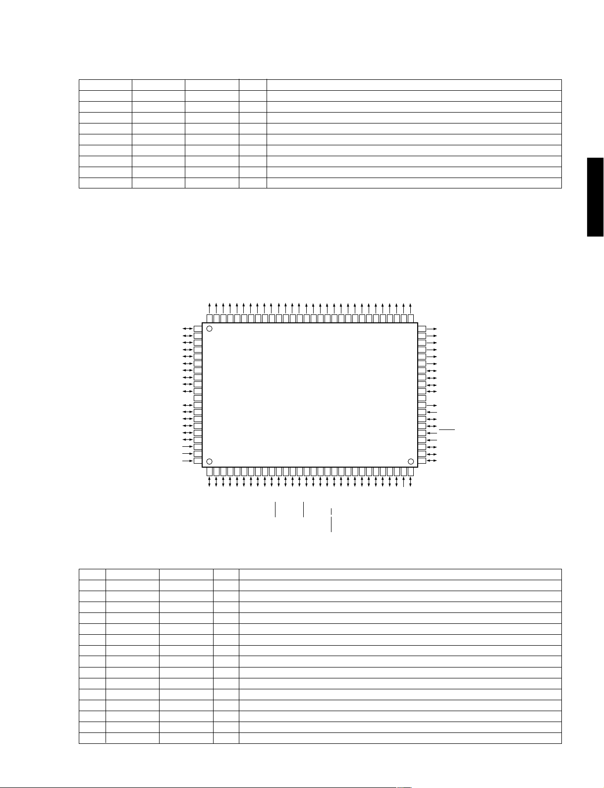
IC8 : M38199EF [INPUT P.C.B.]
8 bit
µ-COM (SYSTEM CPU)
No.
16
17
18
19
20
21
22
23
24
25
26
27
GX-707/VCD
28
29
30
31
32
33
34
35
36
37
38
39
40
41
42
43
44
45
46
47
48
49
50
51
52
53
54
55
56
57
58
59
60
61
62
63
64
65
66
67
68
69
70
71
72
73
74
75
Port
SCLK2
SO2
SI2
P67
SCLK1
SO1
SI1
P63
P62
P61
P60
P47
P46
INT1
INT4
INT3
INT2
P41
INT0
/RESET
XCIN
XCOUT
XIN
XOUT
VSS
P27
P26
P25
P24
P23
P22
P21
P20
P17
P16
P15
P14
P13
P12
P11
P10
P07
P06
P05
P04
P03
P02
P01
P00
P37
P36
P35
P34
P33
P32
P31
P30
P97
P96
P95
Name
TUCLK
TUDO
TUDATA
/STAD
SYSCK
SYSO
SYSI
TUMUTE
/AMPMUTE
CDCE
CDRES
MDCE
MDRES
ACIN
PDN
REMO
STEIN
RESET
XCIN
XCOUT
XIN
XOUT
GND
SPEA
SPEB
SPEC
SPESEL
DLCE
KALATCH
FLRES
FLCE
TUCE
STLED
TMLED
/BC
TEST0
TEST1
DSEL0
DSEL1
PRON
SRON
/SMUTE
/A
/YMA
IN1B
IN1A
IN2A
IN2B
RECA
RECB
VSEL0
VSEL1
VCR
PBMUTE
RMUTE
REC
BIAS
DOLBY
I/O
LC72131/LC72720/M65853FP/LA2787/LV1017/LC75393/LC7536Y CLK OUT
O
LC72131/LC72720/M65853FP/LA2787/LV1017/LC75393/LC7536Y DATA OUT
O
LC72131/LC72720 DATA IN
I
STATION IN (TUNER) [L : STATION AVAILABLE]
I
SYSTEM COMMAND CLOCK
O
SYSTEM COMMAND OUT
O
SYSTEM COMMAND IN
I
TUNER MUTE [H : MUTE ON]
O
AMP MUTE [L : MUTE ON]
O
SYSTEM COMMUNICATION CD CE
O
CD RESET
O
SYSTEM COMMUNICATION MD CE
O
MD RESET
O
POWER DOWN AC PULSE IN
I
MD POWER DOWN
O
OPEN
REMOTE CONTROL SIGNAL IN
I
TUNER STEREO/MONO DETECT
I
OPEN
RESET
I
32.768 kHz IN (SUB CLOCK)
I
32.768 kHz OUT (SUB CLOCK)
O
8 MHz IN (MAIN CLOCK)
I
8 MHz OUT (MAIN CLOCK)
O
GND
O
SPECTRUM ANALYZER (BA3835F) A OUT
O
SPECTRUM ANALYZER (BA3835F) B OUT
O
SPECTRUM ANALYZER (BA3835F) C OUT
O
SPECTRUM ANALYZER (BA3835F) SEL OUT
O
LA2787/LV1017 CE
O
KARAOKE IC M65853 LATCH
O
FL DRIVER RESET
O
FL DRIVER CE
O
LC72131/LC72720/LC75393 CE
O
STANDBY LED ON [ H : LED ON ]
O
TIMER LED ON [ H : LED ON ]
O
PRO LOGIC IC CONTROL-BC (Note 1)
O
TEST PORT
O
TEST PORT
O
MD DIGITAL INPUT SELECT
O
MD DIGITAL INPUT SELECT
O
POWER RELAY CONTROL [ H : ON ]
O
SPEAKER RELAY CONTROL [ H : ON ]
O
SUB WOOFER MUTE [ L : MUTE ON ]
O
PRO LOGIC IC CONTROL-A [ H : ON ] (Note 1)
O
Y MERSION ON [ L : ON ]
O
4052 INPUT SELECT (Note 2)
O
4052 INPUT SELECT (Note 2)
O
4052 INPUT SELECT (Note 3)
O
4052 INPUT SELECT (Note 3)
O
4066 CONTROL
O
4066 CONTROL
O
LA7956 INPUT SELECT (Note 4)
O
LA7956 INPUT SELECT (Note 4)
O
VCR REC INHIBIT [ H : INHIBIT]
O
DECK PLAYBACK MUTE
O
DECK REC MUTE
O
DECK AMP REC
O
DECK BIAS ON
O
DOLBY ON
O
Function
27
IC8 : M38199EF [INPUT P.C.B.]
8 bit
µ-COM (SYSTEM CPU)
GX-707/GX-707VCD
No.
76
77
78
79
80
81
82
83
84
85
86
87
88
89
90
91
92
93
94
95
96
97
98
99
100
Port
P94
P93
P92
P91
P90
P87
P86
P85
P84
P83
P82
P81
P80
PA7
PA6
VCC
PA5
PA4
PA3
PA2
PA1
PA0
VEE
AVSS
VREF
Name
TPEQ
SOL
CPM
CLOSE
OPEN
ENVA
ENVB
ENMA
ENMB
/HP
MIC
CASS
PLSW
CRO2
/IPRT
+5V
CLSW
RECINHF
RECINHR
OPSW
REEL
MUSIC
VEE
AVSS
VREF
I/O
O
TAPE EQUALIZER SELECT [ H : 120 µ]
O
DECK SOLENOID ON
O
DECK CAPSTAN MOTOR ON
O
TAPE LOADING MOTOR CLOSE
O
TAPE LOADING MOTOR OPEN
I
VR ENCODER A
I
VR ENCODER B
I
MD ENCODER A
I
MD ENCODER BHEAD PHONE DETECT [L : HP DETECT]
I
MIC DETECT
I
CASSETTE IN DETECT
I
DECK MECHA PLAY POSITION DETECT
I
CrO2 (70 µs) POSITION DETECT
I
AMP OVER CURRENT DC VOLTAGE DETECT [L : ABNORMAL DETECT]
I
+5V
DECK CLOSE SW
I
REC INHIBIT FORWARD (SIDE-A)
I
REC INHIBIT REVERSE (SIDE-B)
I
DECK OPEN SW
I
REEL MOTOR PULSE DETECT
I
TAPE MUSIC SENSOR
I
GND
GND
+5V
Function
GX-707/VCD
(Note 1) Pin 52, 60
/BC /A PROGRAM
(Pin 52) (Pin 60)
0 0 OFF YMERSION
1 0 PROLOGIC 3STEREO HALL
0 1 TEST MODE
(Note 2) Pin 62, 63
IN1B IN1A FUNCTION
(Pin 62) (Pin 63)
0 0 AUX
0 1 TUNER
1 0 TAPE
1 1 CD/VCD
(Note 3) Pin 64, 65
IN2A IN2B FUNCTION
(Pin 64) (Pin 65)
0 0 IC3 OUT
0 1 LD/TV
1 1 VCR
(Note 4) Pin 68, 69
VSEL0 VSEL1 FUNCTION
(Pin 68) (Pin 69)
0 0 OFF
1 0 VCR
0 1 LD/TV
1 1 VCD
28

GX-707/GX-707VCD
IC5 : MN35511AL [CD/VCD P.C.B.]
Signal Processor & Controller
60
VDD
57
VSS
4
DVDD1
5
DVSS1
18
/RST
71
/TEST
32
FE
33
TE
34
RFENV
37
TRCRS
35
VDET
39
GX-707/VCD
BDO
/RFDET
OFT
38
36
A/D CONVERTER
INPUT PORT
SERVO
TIMING GENERATOR
STAT
X1X2XSEL
58 59 5617
TIMING
GENERATOR
PITCH CONTROL
MICRO COMPUTER
OUTPUT
PORT
SMCK/FCLK49VCOF69CK3848MDATA7MCLK9MLD44ARF46DRF45IREF47DSLF48PLLF52EFM53PCK/RESY67AVDD62AVSS15SUBQ14SQCK20CLVS/FLAG668DEMPO73SUBC
19
CLV
SERVO
SUBCODE
BUFFER
INTERFACE
SERVO
CPU
CONVERTER
D/A
VCO
DSL • PLL VCO
EFM DEMODULATION
SYNC INTERPOLATION
SUBCODE DEMODULATION
CIRC ERROR CORRECTION
DEINTERLEAVE
INTER POLATION
SOFT MUTING
DIGITAL
ATTENUATION
PEAK DETECT
AUTO CUE
16k
SRAM
DIGITAL
AUDIO
INTERFACE
72
SBCK2
74
SBCK75CLDCK13BLKCK55CRC
SDATI80BCKI79LRCKI77DEMPI/TEST2
IOSEL
78
70
DIGITAL DE-EMPHASIS
8 TIMES
OVER SAMPLING
DIGITAL FILTER
DD type
DAC
PEM
(L)
PLL
VCO 2
PEM
(R)
61
VCOF2
41
4010 43
11
30
28
27
22
25
42
29
21
16
1
26
TRV
TVD
TRD
ECS
SENSE
1
2
3
4
5
6
7
8
9
Name
BCLK
LRCK
SRDATA
DVDD1
DVSS1
TX
MCLK
MDATA
MLD
SENSE
FLOCK
TLOCK
BLKCK
SQCK
SUBQ
DMUTE
STAT
RST
SMCK/
FCLK
CLVS/
FLAG6
TRV
TVD
PC
ECM
ECS
KICK
TRD
FOD
VREF
FBAL
TBAL
FE
I/O
Bit clock output for SR DATA
O
L/R identification signal output
O
Serial data output
O
Power supply for digital circuit (+5)
I
GND for digital circuit
I
Digital audio interface output signal
O
Microprocessor command clock signal input (data latched at leading edge)
I
Microprocessor command data input
I
Microprocessor command load signal input (L : LOAD)
I
Sense signal output (OFT, FESL, NACEND, NAJEND, SFG, NWTEND)
O
Focus servo drawing signal (L : when drawn)
O
Tracking servo drawing signal (L : when drawn)
O
Sub code block clock signal (BLKCK=75Hz)
O
Clock input for sub-code Q register
I
Sub-code Q code output
O
Muting input (H : MUTE)
I
Status signal (CRC, STCNT, CLVS, TTSTOP, SQOK, RESY, FCLV, FLAG6, SENSE ,/FLOCK, /RFDET, /TLOCK)
O
Reset input (L : RESET)
I
4.2336MHz clock signal output SMCK when command is defaulted. (Note 1) (NC)
O
SMCK (8.4672MHz), FCLK (7.35kHz) or “L” fixed is selected when command is switched.
With command defaulted : CLVS when IOSEL=H, FLAG6 when IOSEL=L (NC)
O
These settings can be reversed by command (FLAG6 when IOSEL=H).
Traverse (Feed) forced feed output 3-State
O
Traverse (Feed) drive output
O
Spindle motor ON signal L : ON (default) (NC)
O
Spindle motor drive signal (forced mode output) 3-State
O
Spindle motor drive signal (servo error signal output)
O
Kick pulse output 3-State
O
Tracking drive output
O
Focus drive output
O
Reference voltage for DA output block (TVD, ECS, TRD, FOD, FBAL, TBAL)
I
Focus balance adjustment output
O
Tracking balance adjustment output
O
Focus error signal input (analog input)
I
Pin No.
10
11
12
13
14
15
16
17
18
19
20
21
22
23
24
25
26
27
28
29
30
31
32
29
(Note 1) At the SMCK/FCLK pin, output does not stop while /RST=L.
/FLOCK12/TLOCK
FOD
FBAL31TBAL
TOFS
LDON
WVEL
PLAY/TRVSTP
VREF
KICK
DMUTE
BCLK
3
2
23PC24
LRCK
SRDATA
ECM
6TX76
54
51
63
64
FLAG
AVSS2
OUT1C
IPFLAG
OUT1D66OUT2C
65
OUT2D
50
AVDD2
Function
 Loading...