

Page 1

2016 WaveRunner
FZR SVHO
OWNER’S/OPERATOR’S MANUAL
Read this manual carefully
before operating this watercraft.
F3L-F8199-73-E0
Page 2

Read this manual carefully before operating this watercraft. This manual
should stay with the WaveRunner if it is sold.
Page 3
Important manual information
Declaration of Conformity for Personal Watercraft (PWC)
with the requirements of Directive 94/25/EC, as amended by Directive 2003/44/EC
Name of PWC Manufacturer: YAMAHA MOTOR CO., LTD.
Name / Title: Y. Henmi / General Manager of Engineering Section, Boat Business Unit
Address: 2500 Shingai, Iwata, Shizuoka 438-8501, Japan
Name of Authorised Representative: YAMAHA MOTOR EUROPE N.V.
Address: Koolhovenlaan 101, 1119 NC Schiphol-Rijk, The Netherlands
Name of Notified Body for exhaust and noise emission assessment: SNCH
GX1800-R / FZR SVHO
0499
Address: 11, route de Luxembourg BP 32, Sandweiler, L-5230. Luxembourg
US-YAMA0001H516
Conformity assessment module used:
for construction:
for exhaust emissions:
for noise emissions:
DESCRIPTION OF CRAFT
DESCRIPTION OF ENGINE
A
A
Craft model Identification Number, starting from :
Model name / Commercial name :
CDesign Category :
Other Community Directives applied
Electromagnetic Compatibility Directive 2004/108/EC and 2014/30/EU
EN 55012:2007/A1:2009
Directive 2006/42/EC relating to Machinery.
Standards
EN 61000-6-2:2005
D
AaAaB+C
B+C
B+D
B+D
B+E
B+E
B+F
B+FGG
G
H
H
H
Engine Type:
PWC engine
Combustion cycle:
4 stroke
Fuel Type:
Petrol
ESSENTIAL REQUIREMENTS
IDENTIFICATION OF ENGINE COVERED BY THIS DECLARATION OF CONFORMITY
Name of engine model
6EV
Name / ID number of Notified Body
SNCH / 0499
EC Type–examination certificate number
SNCH*94/25*2003/44*0076
(identification of the person empowered to sign on behalf of the manufacturer)
Signature:
(or an equivalent marking)
Date and place of issue:
Essential requirements
standards
other normative
document / method
technical file
Please specify in more detail
(* = mandatory standard)
I.A design and construction EN ISO 13590
I.B exhaust emission *EN ISO 8178-1
I.C noise emission *EN ISO 14509
*
*
This declaration of conformity is issued under the sole responsibility of the manufacturer. I declare on behalf of the PWC
manufacturer that the craft model(s) and engine(s) mentioned above complies (comply) with all applicable essential
requirements in the way specified and is (are) in conformity with the type(s) for which above mentioned EC type-examination
certificate(s) has (have) been issued.
ID Number:
1st / August / 2015, Shizuoka, Japan
EJU42753
Page 4
Important manual information
WARNING
NOTICE
TIP:
EJU30193
To the owner/operator
Thank you for choosing a Yamaha watercraft.
This owner’s/operator’s manual contains information you will need for proper operation,
maintenance, and care. If you have any questions about the operation or maintenance of
your watercraft, please consult a Yamaha
dealer.
This manual is not a course on boating safety
or seamanship. If this is your first watercraft,
or if you are changing to a type of watercraft
you are not familiar with, for your own comfort and safety, please ensure that you obtain
proper training or practice before operating
the watercraft by yourself. In addition, a
Yamaha dealer or boating organization will be
pleased to recommend local sea schools, or
competent instructors.
In this manual, information of particular importance is distinguished in the following
ways:
This is the safety alert symbol. It is used
to alert you to potential personal injury hazards. Obey all safety messages that follow
this symbol to avoid possible injury or death.
EWJ00072
EJU40411
Because Yamaha has a policy of continuing
product improvement, this product may not
be exactly as described in this owner’s/operator’s manual. Specifications are subject to
change without notice.
This manual should be considered a permanent part of this watercraft and should remain
with it even if the watercraft is subsequently
sold.
EJU30233
WaveRunner FZR SVHO
OWNER’S/OPERATOR’S MANUAL
©2015 by Yamaha Motor Co., Ltd.
1st Edition, August 2015
All rights reserved.
Any reprinting or unauthorized use
without the written permission of
Yama h a M o tor C o . , Ltd .
is expressly prohibited.
Printed in U.S.A.
A WARNING indicates a hazardous situation which, if not avoided, could result in
death or serious injury.
ECJ00092
A NOTICE indicates special precautions
that must be taken to avoid damage to the
watercraft or other property.
A TIP provides key information to make procedures easier or clearer.
Page 5

Table of contents
General and important labels........... 1
Identification numbers .................... 1
Primary Identification (PRI-ID)
number............................................ 1
Craft Identification Number (CIN)....... 1
Engine serial number.......................... 1
Manufactured date label .................... 2
Model information ........................... 2
Builder’s plate .................................... 2
Important labels .............................. 4
Warning labels.................................... 5
Other labels........................................ 9
Safety information ........................... 11
Limitations on who may operate
the watercraft ............................. 11
Cruising limitations........................ 12
Operation requirements ................ 13
Recommended equipment ........... 15
Hazard information........................ 16
Watercraft characteristics ............. 16
Safe boating rules ......................... 18
Enjoy your watercraft
responsibly................................. 18
Description....................................... 20
Watercraft glossary ....................... 20
Location of main components ...... 21
Control function operation ............. 25
Watercraft control functions ......... 25
Remote control transmitter .............. 25
Yamaha Security System ................. 26
Engine stop switch .......................... 27
Engine shut-off switch .................... 27
Start switch ..................................... 27
Throttle lever .................................... 28
Steering system ............................... 28
Telescopic steering system.............. 29
Cooling water pilot outlets ............... 29
Water separator................................ 30
Watercraft operation ...................... 31
Watercraft operation functions ..... 31
Reverse system................................ 31
Quick Shift Trim System
(Q.S.T.S.)....................................... 31
Watercraft operation modes ......... 33
Low RPM Mode ............................... 33
Instrument operation ...................... 35
Dual analog meter unit.................. 35
Speedometer.................................... 35
Tachometer ...................................... 35
Information display........................... 36
Equipment operation ...................... 40
Equipment..................................... 40
Seats ................................................ 40
Reboarding grip................................ 41
Reboarding step............................... 41
Bow eye............................................ 42
Stern eyes ........................................ 42
Storage compartments .................... 42
Fire extinguisher holder and cover... 45
Operation and handling
requirements ................................... 47
Fuel requirements ......................... 47
Fuel................................................... 47
Engine oil requirements ................ 49
Engine oil.......................................... 49
Draining the bilge water................ 51
Draining the bilge water on land....... 51
Draining the bilge water on water .... 51
Transporting on a trailer................ 52
First-time operation ........................ 53
Engine break-in............................. 53
Pre-operation checks ..................... 54
Pre-operation checklist .................... 54
Pre-operation check points .......... 56
Pre-launch checks ........................... 56
Post-launch checks.......................... 64
Page 6

Table of contents
Operation ......................................... 65
Operating your watercraft ............. 65
Getting to know your watercraft ...... 65
Learning to operate your
watercraft...................................... 65
Riding position ................................. 66
Launching the watercraft ................. 66
Starting the engine on water ............ 66
Stopping the engine......................... 67
Leaving the watercraft...................... 67
Operating the watercraft .................. 67
Turning the watercraft...................... 68
Stopping the watercraft ................... 69
Operating the watercraft in
reverse .......................................... 70
Boarding the watercraft ................... 70
Starting off........................................ 73
Capsized watercraft ......................... 74
Beaching and docking the
watercraft...................................... 75
Operating in weeded areas.............. 75
After removing the watercraft from
the water....................................... 76
Care and storage............................. 77
Post-operation care ...................... 77
Flushing the cooling water
passages....................................... 77
Cleaning the watercraft.................... 78
Battery care...................................... 78
Long-term storage ........................ 81
Cleaning ........................................... 81
Lubrication ....................................... 81
Rustproofing..................................... 82
Specifications.................................. 88
Specifications ............................... 88
Trouble recovery ............................. 89
Troubleshooting............................ 89
Troubleshooting chart ...................... 89
Emergency procedures ................ 92
Cleaning the jet intake and
impeller ......................................... 92
Jumping the battery ......................... 93
Replacing the fuses.......................... 93
Towing the watercraft....................... 95
Submerged watercraft ..................... 95
Index................................................. 96
Maintenance .................................... 83
Maintenance.................................. 83
Tool kit.............................................. 83
Removing and installing the engine
cover ............................................. 83
Periodic maintenance chart ............. 85
Engine oil and oil filter ...................... 87
Page 7
General and important labels
1
MODEL
YAMAHA MOTOR CO., LTD.
ASSEMBLED IN U.S.A. FROM AMERICAN AND JAPANESE
COMPONENTS.
ASSEMBLÉ AUX ÉTATS-UNIS DE PIÈCES AMÉRICANES ET
JAPONAISES.
PRI-I.D.
F3L
F3L
1
1
EJU36452
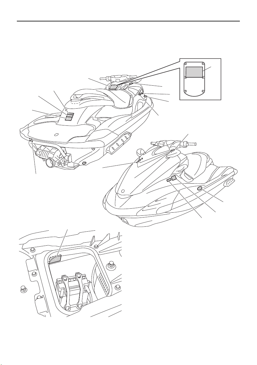
Identification numbers
Record the Primary Identification (PRI-ID)
number, Craft Identification Number (CIN),
and engine serial number in the spaces provided for assistance when ordering spare
parts from a Yamaha dealer. Also record and
keep these ID numbers in a separate place in
case your watercraft is stolen.
EJU42521
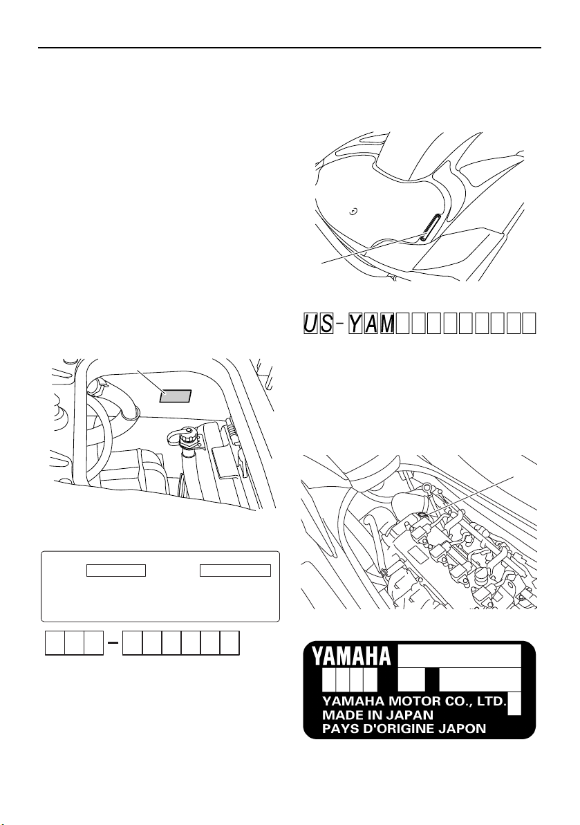
Primary Identification (PRI-ID) number
The PRI-ID number is stamped on a plate attached inside the engine compartment. (See
page 40 for seat removal and installation procedures and page 45 for information on the
removable watertight storage compartment.)
MODEL:
GX1800-R (FZR SVHO)
EJU36551
Craft Identification Number (CIN)
The CIN is stamped on a plate attached to
the aft deck.
1 Craft Identification Number (CIN) location
EJU40471
Engine serial number
The engine serial number is stamped on a
plate attached to the engine unit. (See page
40 for seat removal and installation procedures and page 83 for engine cover removal
and installation procedures.)
1 Primary Identification (PRI-ID) number loca-
tion
1 Engine serial number location
1
Page 8
General and important labels
1
1
EJU42031
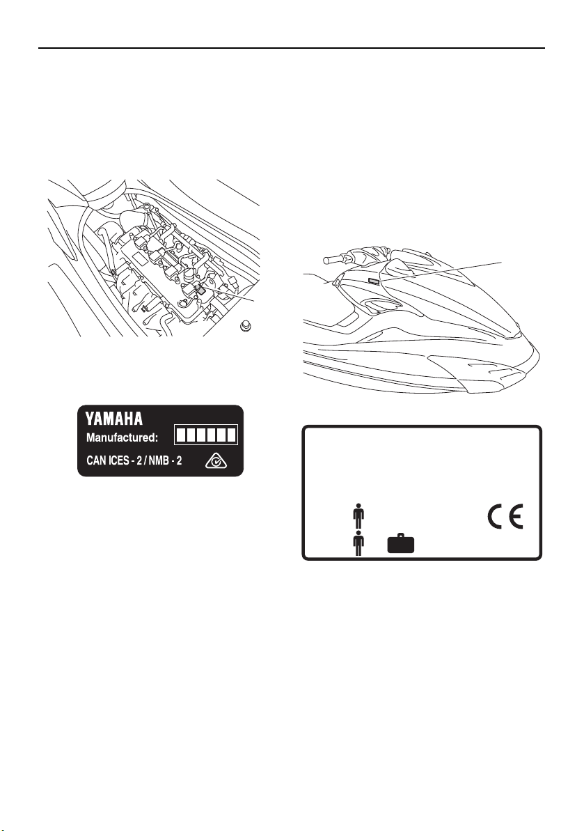
Manufactured date label
This label is attached to the top of the cylinder head. (See page 40 for seat removal and
installation procedures and page 83 for engine cover removal and installation procedures.)
1 Manufactured date label location
EJU30321
Model information
EJU30332
Builder’s plate
Watercraft with this label conform to certain
portions of the European Parliament directive
relating to machinery.
Part of the information is given on the builder’s plate affixed on the craft. A full explanation of this information is given in the relevant
sections of this manual.
1 Builder’s plate location
YAMAHA MOTOR CO., LTD.
2500 Shingai, Iwata, Shizuoka, Japan
WATERCRAFT DESIGN CATEGORY : C
MAXIMUM CAPACITIES
Max. 2
Max. + = 160kg (353 lbs)
Design category of this personal watercraft: C
Category C:
This watercraft is designed to operate in
winds up to Beaufort force 6 and the associated wave heights (significant wave heights
up to 2 m (6.56 ft); see the following TIP).
2
Such conditions may be encountered in exposed inland waters, in estuaries, and in
coastal waters in moderate weather conditions.
Page 9

General and important labels
TIP:
The significant wave height is the mean
height of the highest one-third of the waves,
which approximately corresponds to the
wave height estimated by an experienced
observer. However, some waves will be double this height.
3
Page 10
General and important labels
1
5
4
10
6
8
7
12
15
11
13
2
9
16
3
14
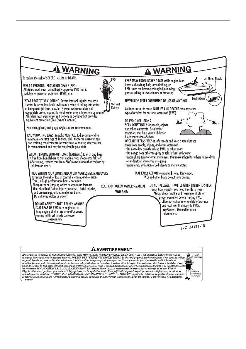
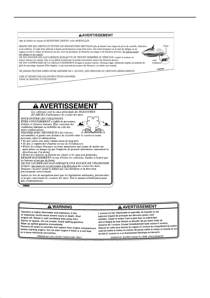
EJU30453
Important labels
Read the following labels before using this watercraft. If have any questions, consult a
Yamaha dealer.
4
Page 11
General and important labels
F2S-U41B1-20
1
2
EJU35914
Warning labels
If any of these labels are damaged or missing, contact a Yamaha dealer for replacements.
5
Page 12
General and important labels
F
2
S
-U
41
B
1
-3
0
F0M-U41B2-11
F
3J-U
415B
-30
3
4
5
6
Page 13
General and important labels
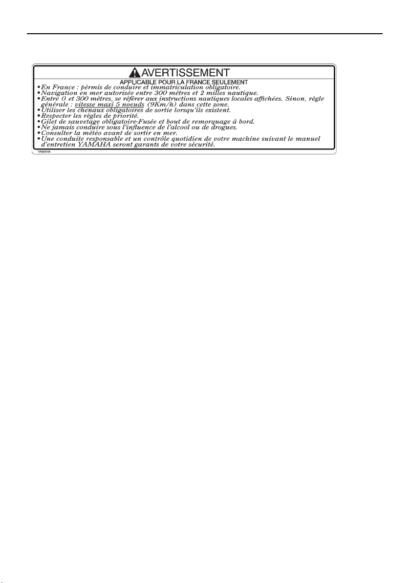
WARNING
AVERTISSEMENT
WARNING
AVERTISSEMENT
(F2R-U41E1-10)
(F2R-U41E1-10)
F3K-U41D5-10
F0V-U41DB-12
6
78
9
7
Page 14
General and important labels
GJ3-U416H-01
10
8
Page 15
(F2R-U41E1-10)
F3J-U419B-30
F1B-U41F5-11
11
12
13
14
General and important labels
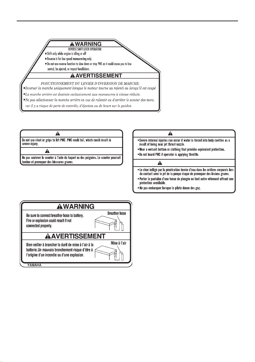
EJU36262
Other labels
9
Page 16
General and important labels
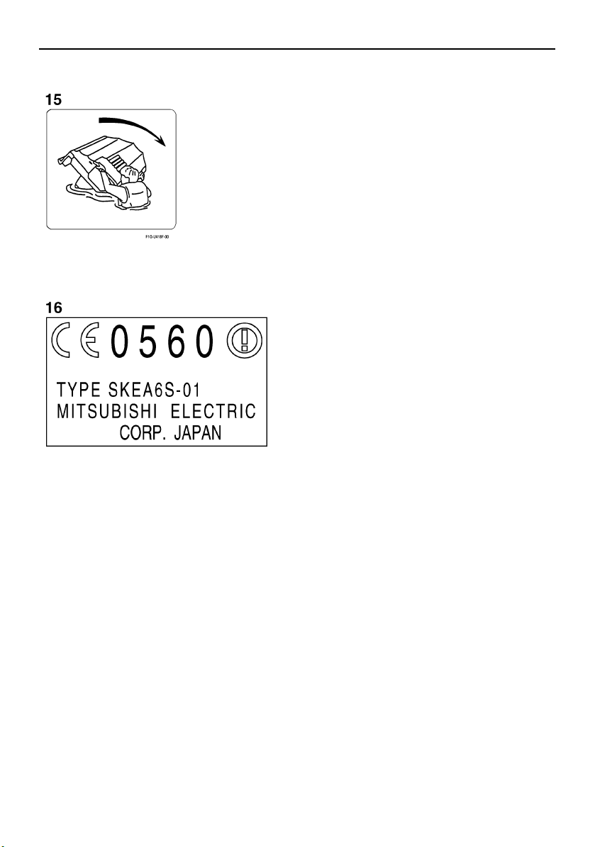
The following label indicates the correct direction to upright a capsized watercraft.
The following CE marking is located on the back of the remote control transmitter.
10
Page 17
Safety information
EJU30683
The safe use and operation of this watercraft is dependent upon the use of proper
riding techniques, as well as upon the
common sense, good judgment, and expertise of the operator. Before using this
watercraft, make sure that its use is permitted under local laws, bylaws, and regulations, and always operate the watercraft
in full conformity with any requirements
and limitations imposed. Every operator
should know the following requirements
before riding the watercraft.
Before operating the watercraft, read this
owner’s/operator’s manual, the Riding
Practice Guide, the Riding Instruction card,
and all labels on the watercraft. These materials should give you an understanding of
the watercraft and its operation.
Never allow anyone to operate this water-
craft until they too have read this owner’s/operator’s manual, the Riding Practice
Guide, the Riding Instruction card, and all
labels.
EJU30721
Limitations on who may
operate the watercraft
Yamaha recommends a minimum operator
age of 16 years old.
Adults must supervise use by minors.
Know your local operator age and training
requirements.
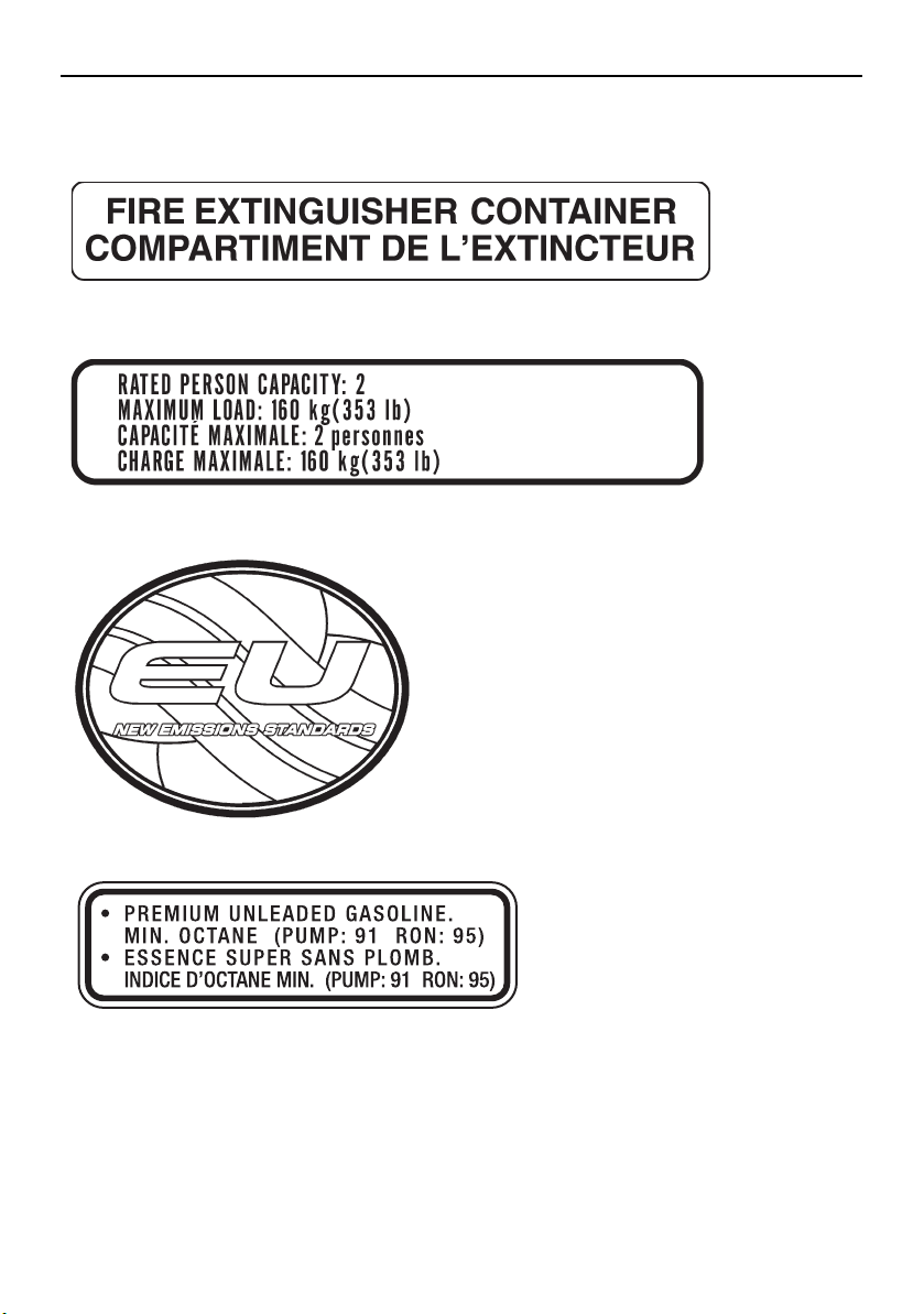
This watercraft is designed to carry the op-
erator and 1 passenger. Never exceed the
maximum load limit or allow more than 2
persons to ride the watercraft at any time.
Maximum load:
160 kg (353 lb)
Load is the total weight of cargo, operator, and passenger.
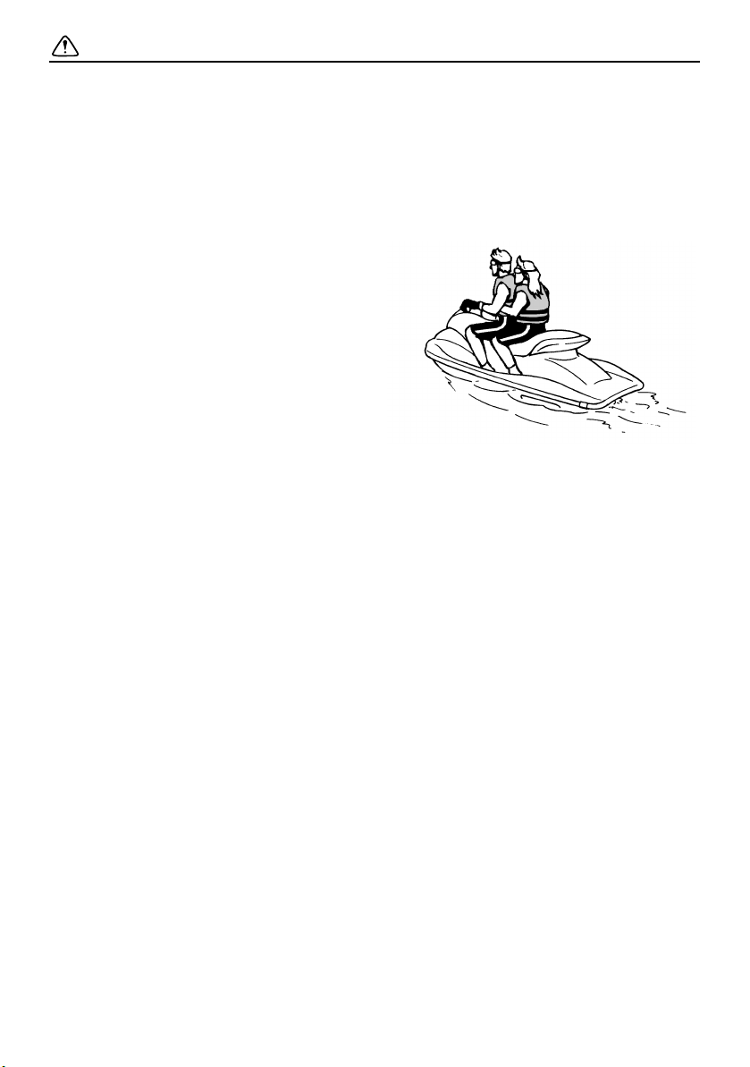
Do not operate the watercraft with a pas-
senger on board until you have considerable practice and experience riding alone.
Operating the watercraft with a passenger
requires more skill. Take the time to become accustomed to the handling characteristics of the watercraft before trying any
difficult maneuvers.
11
Page 18
Safety information
60 cm (2 ft)
EJU30762
Cruising limitations
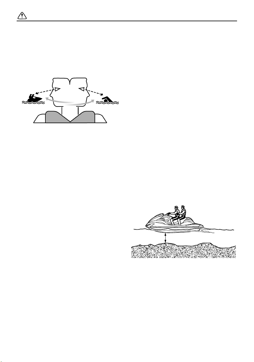
Scan constantly for people, objects, and
other watercraft. Be alert for conditions
that limit your visibility or block your vision
of others.
Operate defensively at safe speeds and
keep a safe distance away from people,
objects, and other watercraft.
Do not follow directly behind watercraft or
other boats.
Do not go near others to spray or splash
them with water.
Avoid sharp turns or other maneuvers that
make it hard for others to avoid you or understand where you are going.
Avoid areas with submerged objects or
shallow water.
Take early action to avoid collisions. Re-
member, watercraft and other boats do not
have brakes.
Do not release the throttle lever when trying
to steer away from objects—you need
throttle to steer. Always check throttle and
steering controls before starting the watercraft.
Ride within your limits and avoid aggres-
sive maneuvers to reduce the risk of loss of
control, ejection, and collision.
This is a high performance boat—not a toy.
Sharp turns or jumping wakes or waves
can increase the risk of back/spinal injury
(paralysis), facial injuries, and broken legs,
ankles, and other bones. Do not jump
wakes or waves.
Do not operate the watercraft in rough wa-
ter, bad weather, or when visibility is poor;
this may lead to an accident causing injury
or death. Be alert to the possibility of adverse weather. Take note of weather forecasts and the prevailing weather
conditions before setting out on your watercraft.
As with any water sport, you should not op-
erate your watercraft without someone else
nearby. If you operate further than swimming distance from shore, you should be
accompanied by another boat or watercraft, but make sure you stay a safe distance away. It’s good, common sense.
Never operate in water that is less than 60
cm (2 ft) deep from the bottom of the watercraft, otherwise you increase your
chance of hitting a submerged object,
which could result in injury.
This watercraft is not equipped with light-
ing required for night operation. Do not operate the watercraft after sunset or before
dawn, otherwise you increase the risk of
12
Page 19
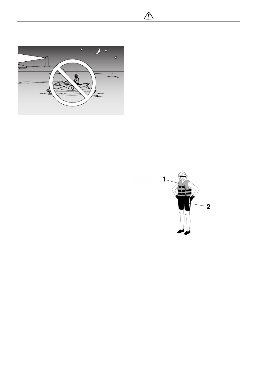
Safety information
colliding with another boat, which could result in severe injury or death.
Follow navigation rules, and state/provin-
cial and local laws that apply to watercraft.
EJU30802
Operation requirements
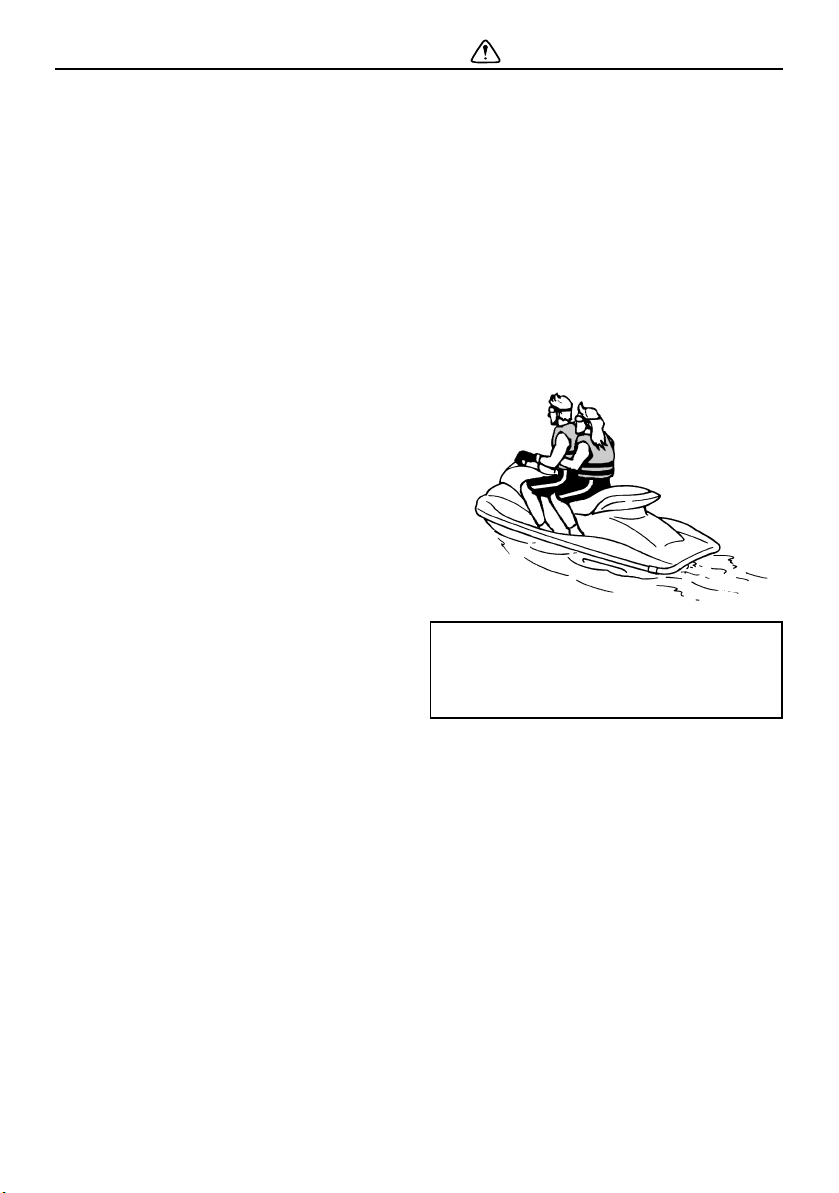
All riders must wear a personal flotation de-
vice (PFD) that is approved by the appropriate authorities and is suitable for
personal watercraft use.
Wear protective clothing. Severe internal
injuries can occur if water is forced into
body cavities as a result of falling into the
water or being near the jet thrust nozzle.
Normal swimwear does not adequately
protect against forceful water entry into the
rectum or vagina. All riders must wear a
wetsuit bottom or clothing that provides
equivalent protection. Such clothing includes thick, tightly woven, sturdy and
snug-fitting apparel such as denim, but
does not include spandex or similar fabrics, like those used in bicycle shorts.
1 Authority-approved PFD
2 Wetsuit bottom
Eye protection is recommended to keep
wind, water, and glare from the sun out of
your eyes while you operate your watercraft. Restraining straps for eyewear are
made which are designed to float should
your eyewear fall in the water.
Footwear and gloves are recommended.
You must decide whether to wear a helmet
while you ride for recreation. You should
know that a helmet could help protect you
13
Page 20
Safety information
in certain kinds of accidents and that it
could injure you in others.
A helmet is designed to provide some head
protection. Although helmets cannot protect against all foreseeable impacts, a helmet might reduce your injuries in a collision
with a boat or other obstacle.
A helmet may have potential safety hazards, as well. Falling into the water could
risk the chance of the helmet catching water, commonly known as “bucketing”, and
the resulting strain on your neck could
cause choking, severe and permanent
neck injuries, or death. A helmet could also
increase the risk of an accident if it reduces
your vision or hearing, or if it distracts you
or increases your fatigue.
How should you decide if a helmet’s potential safety benefits outweigh its potential
risks for you? Consider your particular riding conditions. Consider factors such as
your riding environment and your riding
style and ability. Also consider the likelihood of traffic congestion, and the water
surface conditions.
If you decide to wear a helmet based upon
your riding circumstances, choose one
carefully. Look for a helmet designed for
personal watercraft use, if possible. If you
will be engaging in closed-course competition, follow the helmet requirements of the
sanctioning organization.
Never operate the watercraft after consum-
ing alcohol or taking other drugs.
For reasons of safety and proper care of
the watercraft, always perform the pre-operation checks listed on page 54 before operating the watercraft.
The operator and passenger should always
keep their feet on the floor of the footwell
when the watercraft is in motion. Lifting
your feet increases the chances of losing
your balance, or hitting objects outside the
watercraft with your feet. Do not give a ride
to a child whose feet cannot reach the floor
of the footwell.
The passenger should firmly hold on to the
operator.
Never allow a passenger to ride in front of
the operator.
Always consult your doctor on whether it is
safe for you to ride this watercraft if you are
pregnant or in poor health.
Do not attempt to modify this watercraft.
Modifications to your watercraft may reduce safety and reliability, and render the
watercraft unsafe or illegal for use.
Attach the engine shut-off cord (lanyard) to
your left wr ist and kee p it fre e from t he h andlebars so that the engine stops if you, the
operator, fall off. After riding, remove the
engine shut-off cord (lanyard) from the wa-
14
Page 21
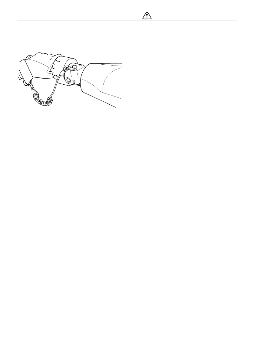
Safety information
tercraft to avoid accidental starting or unauthorized use by children or others.
Scan carefully for swimmers and stay away
from swimming areas. Swimmers are hard
to see and you could accidentally hit someone in the water.
Avoid being hit by another boat. You
should always take the responsibility to
watch for traffic; other boaters may not be
watching for you. If they do not see you, or
if you maneuver more quickly than other
boaters expect, you risk a collision.
Maintain a safe distance from other boats
and watercraft, and also watch for ski
ropes or fishing lines. Obey the “Safe boating rules” and be sure to check behind you
before making a turn. (See “Safe boating
rules” on page 18.)
EJU30841
Recommended equipment
The following items should be carried on
board your watercraft:
Sound-signaling device
You should carry a whistle or other soundsignaling device that can be used to signal
other boats.
Visual distress signals
It is recommended that a pyrotechnic device, which is approved by the appropriate
authorities, be stored in a waterproof container on your watercraft. A mirror can also
be used as an emergency signal. Contact a
Yamaha dealer for more information.
Watch
A watch is helpful so you will know how
long you have been operating the watercraft.
Towline
A towline can be used to tow a disabled
watercraft in an emergency.
15
Page 22

Safety information
EJU36851
Hazard information
Never start the engine or let it run for any
length of time in an enclosed area. Exhaust
fumes contain carbon monoxide, a colorless, odorless gas that may cause loss of
consciousness and death within a short
time. Always operate the watercraft in an
open area.
Do not touch the hot muffler or engine dur-
ing or immediately after engine operation;
they can cause serious burns.
EJU30921
Watercraft characteristics
Jet thrust turns the watercraft. Releasing
the throttle lever completely produces only
minimum thrust. If you are traveling at
speeds above trolling, you will have rapidly
decreasing ability to steer without throttle.
This model is equipped with the Yamaha
Engine Management System (YEMS) that
includes an off-throttle steering (OTS) system. It will activate at planing speeds
should you attempt to steer the watercraft
after releasing the throttle lever. The OTS
system assists in turning by continuing to
supply some thrust while the watercraft is
decelerating, but you can turn more sharply if you apply throttle while turning the handlebars.
The OTS system does not function below
planing speeds or when the engine is off.
Once the engine slows down, the watercraft will no longer turn in response to handlebar input until you apply throttle again or
you reach trolling speed.
Practice turning in an open area without
obstacles until you have a good feel for this
maneuver.
This watercraft is water-jet propelled. The
jet pump is directly connected to the engine. This means that jet thrust will produce
some movement whenever the engine is
running. There is no “neutral” position. You
are in either “forward” or “reverse”, depending upon the shift lever position.
Do not use the reverse function to slow
down or stop the watercraft as it could
cause you to lose control, be ejected, or
impact the handlebars.
This could increase the risk of back/spinal
injury (paralysis), facial injuries, and broken
legs, ankles, and other bones. You could
also damage the shift mechanism.
16
Page 23
Safety information
1
2
2
1
Reverse can be used to slow down or stop
during slow-speed maneuvering, such as
when docking. Once the engine is idling,
shift into reverse and gradually increase
engine speed. Make sure that there are no
obstacles or people behind you before
shifting into reverse.
Keep away from the intake grate while the
engine is on. Items such as long hair, loose
clothing, or PFD straps can become entangled in moving parts, resulting in severe injury or drowning.
Never insert any object into the jet thrust
nozzle while the engine is running. Severe
injury or death could result from coming in
contact with the rotating parts of the jet
pump.
any debris or weeds, which may have collected around the jet intake.
1 Clip
2 Engine shut-off switch
1 Intake grate
2 Jet thrust nozzle
Stop the engine and remove the clip from
the engine shut-off switch before removing
17
Page 24

Safety information
EJU30971
Safe boating rules
Your Yamaha watercraft is legally considered
a powerboat. Operation of the watercraft
must be in accordance with the rules and
regulations governing the waterway on which
it is used.
EJU30992
Enjoy your watercraft
responsibly
You share the areas you enjoy when riding
your watercraft with others and with nature.
So your enjoyment includes a responsibility
to treat these other people, and the lands,
waters, and wildlife with respect and courtesy.
Whenever and wherever you ride, think of
yourself as the guest of those around you.
Remember, for example, that the sound of
your watercraft may be music to you, but it
could be just noise to others. And the exciting
splash of your wake can make waves others
won’t enjoy.
Avoid riding close to shoreline homes and
waterfowl nesting areas or other wildlife areas, and keep a respectful distance from fishermen, other boats, swimmers, and
populated beaches. When travel in areas like
these is unavoidable, ride slowly and obey all
laws.
Proper maintenance is necessary to ensure
that the exhaust emission and sound levels of
your watercraft will continue to be within regulated limits. You have the responsibility to
make sure that the recommended maintenance in this owner’s/operator’s manual is
carried out.
Remember, pollution can be harmful to the
environment. Do not refuel or add oil where a
spill could cause damage to nature. Remove
your watercraft from the water and move it
away from the shoreline before refueling. Dispose of water and any fuel and oil residue in
the engine compartment according to local
regulations. And keep your surroundings
pleasant for the people and wildlife that share
the waterways: don’t litter.
18
Page 25

When you ride responsibly, with respect and
courtesy for others, you help ensure that our
waterways stay open for the enjoyment of a
variety of recreational opportunities.
Safety information
19
Page 26

Description
EJU40303
Watercraft glossary
Trolling speed
“Trolling” is the lowest maneuvering speed. You are applying little or no throttle. The watercraft is down in the water, and there is no wake.
Sub-planing speed
“Sub-planing” is a medium speed. The bow of the watercraft is slightly up from the water surface, but you are still traveling through the water. There is a wake.
Planing speed
“Planing” is a faster speed. The watercraft is more level and is skimming on top of the water.
There is a wake.
Bow
The front end of the watercraft.
Stern
The rear end of the watercraft.
Starboard
The right side of the watercraft when facing forward.
Port
The left side of the watercraft when facing forward.
Bilge water
Water that has collected in the engine compartment.
Yamaha Engine Management System (YEMS)
YEMS is an integrated, computerized management system that controls and adjusts ignition
timing, fuel injection, engine diagnostics, and the off-throttle steering (OTS) system.
20
Page 27
EJU31012
3
4
5
6
10
9
7
8
1
2
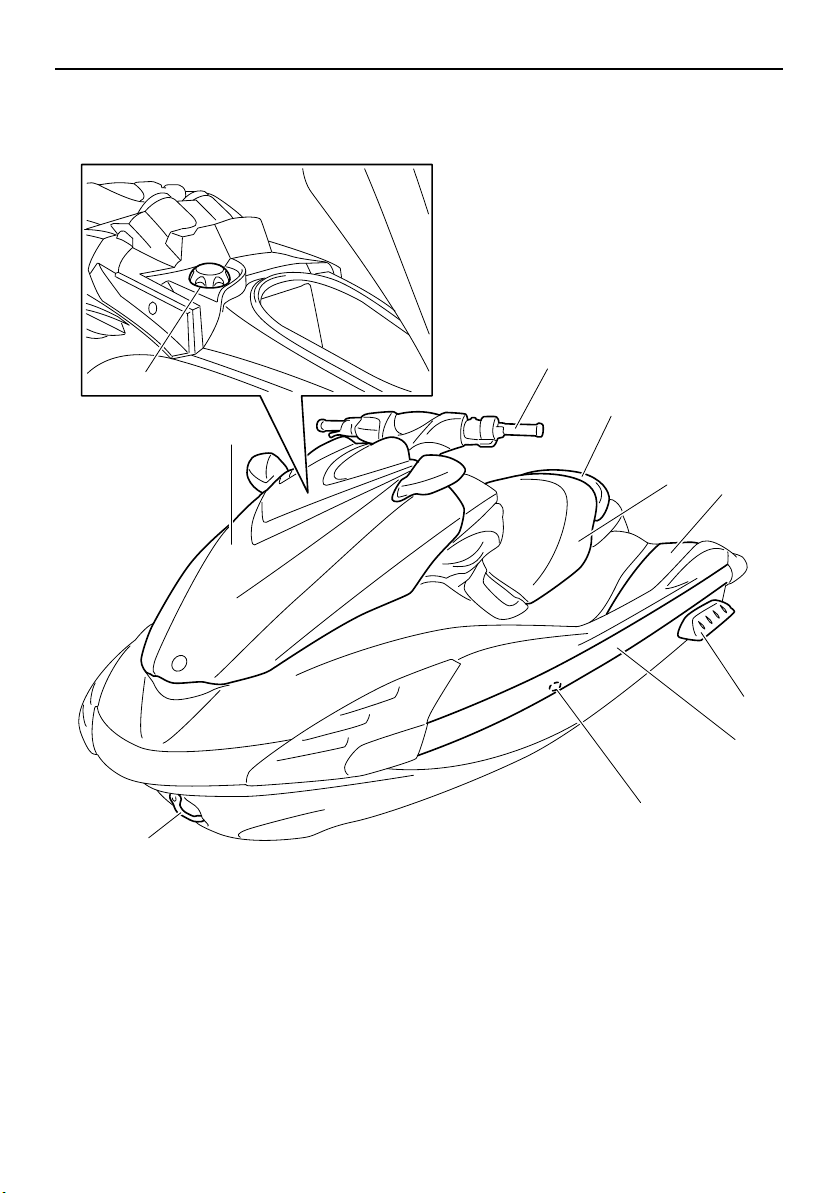
Exterior
Description
Location of main components
1 Fuel filler cap (page 47)
2 Hood
3 Handlebar
4 Rear seat (page 40)
5 Front seat (page 40)
6 Footwell
7 Bow eye
8 Cooling water pilot outlet (page 29)
9 Gunwale
10 Sponson
21
Page 28
Description
2
3
9
8
5
1
7
6
4
11
10
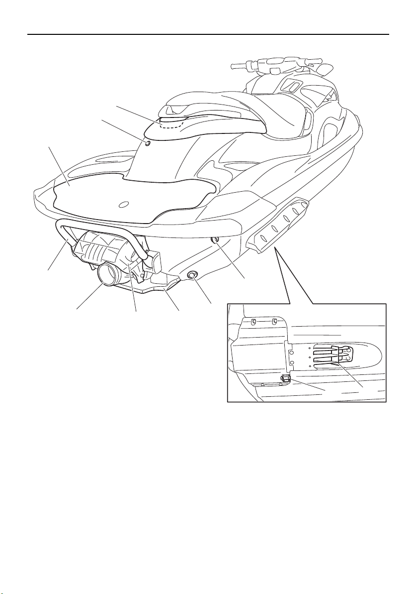
1 Boarding platform
2 Electric bilge pilot outlet
3 Reboarding grip (page 41)
4 Reboarding step (page 41)
5 Jet thrust nozzle
6 Reverse gate (page 31)
7 Ride plate
8 Stern drain plug (page 51)
9 Stern eye (page 42)
10 Speed sensor
11 Intake grate
22
Page 29
Description
1234
67
5
11
12 13 14
15
109
8
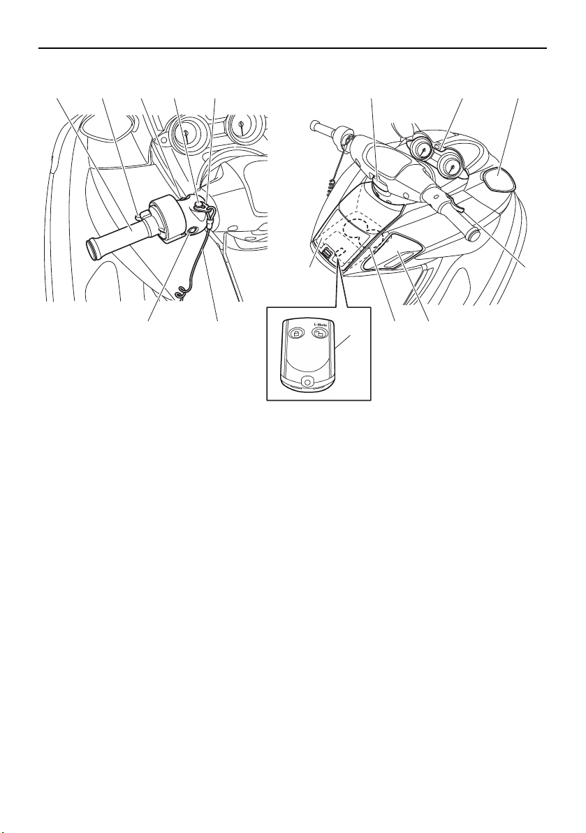
1 Q.S.T.S. selector (page 31)
2 Q.S.T.S. selector lock lever (page 31)
3 Start switch (page 27)
4 Engine shut-off switch (page 27)
5 Clip (page 27)
6 Engine stop switch (page 27)
7 Engine shut-off cord (lanyard) (page 27)
8 Telescopic lock lever (page 29)
9 Dual analog meter unit (page 35)
10 Rearview mirror
11 Glove compartment (page 43)
12 Remote control transmitter (page 25)
13 Beverage holder (page 45)
14 Shift lever (page 31)
15 Throttle lever (page 28)
23
Page 30
Description
1
2
3
4
6
5
10 11
8
9
7
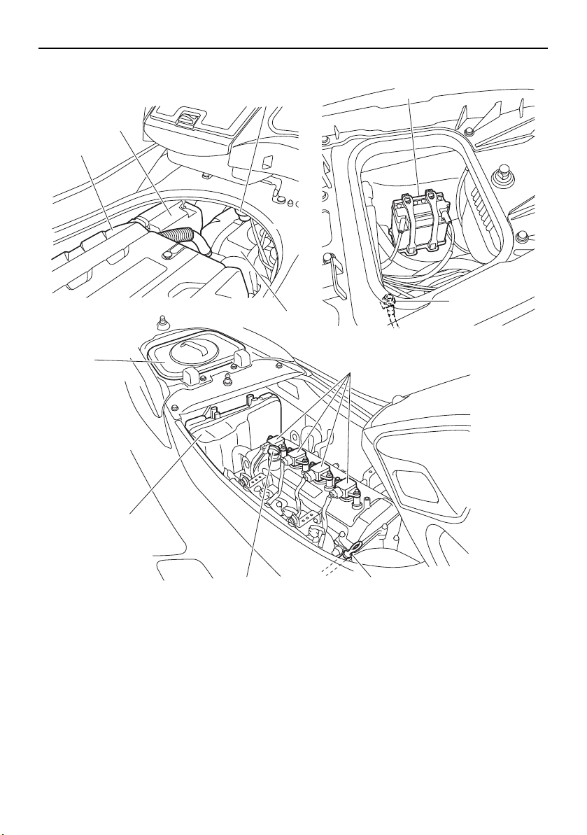
Engine compartment
1 Engine cover
2 Air filter case
3 Water separator (page 30)
4 Fuel tank
5 Battery (page 57)
6 Flushing hose connector
7 Removable watertight storage compart-
ment (page 45)
8 Spark plug/Ignition coil
9 Electrical box
10 Engine oil filler cap (page 49)
11 Dipstick
24
Page 31

Control function operation
NOTICE
1
EJU31026
Watercraft control functions
EJU41391
Remote control transmitter
The Yamaha Security System and Low RPM
Mode settings can be selected by operating
the remote control transmitter. (See page 26
for Yamaha Security System setting procedures and page 33 for Low RPM Mode activation procedures.)
1 Remote control transmitter
Since the watercraft is programmed to recognize the internal code from this transmitter
only, the settings can only be selected with
this transmitter.
If you accidentally lose your remote control
transmitter or if it is not operating properly,
contact a Yamaha dealer.
When operating the watercraft, always keep
the transmitter with you, such as by storing it
in the transmitter holder in the beverage holder, so that it is not lost.
1 Transmitter holder
ECJ00753
The remote control transmitter is not
completely waterproof. Do not submerge the transmitter or operate it underwater. If the transmitter is
submerged, dry it with a soft, dry cloth,
and then check that it is operating properly. If the transmitter is not operating
properly, contact a Yamaha dealer.
Keep the remote control transmitter
away from high temperatures and do
not place it in direct sunlight.
Do not drop the remote control trans-
mitter, subject it to strong shocks, or
place any heavy items on it.
Use a soft, dry cloth to clean the remote
control transmitter. Do not use detergent, alcohol, or other chemicals.
Do not attempt to disassemble the re-
mote control transmitter yourself. Otherwise, the transmitter may not operate
properly. If the transmitter needs a new
battery, contact a Yamaha dealer. Refer
to local hazardous waste regulations
when disposing of transmitter batteries.
25
Page 32

Control function operation
TIP:
TIP:
1
2
L-Mode
1
2
EJU31385
Yamaha Security System
The Yamaha Security System functions to
help prevent unauthorized use or theft of the
watercraft. The lock and unlock modes of the
security system can be selected by operating
the remote control transmitter that is included
with this watercraft. The engine cannot be
started if the lock mode of the security system is selected. The engine can only be started if the unlock mode is selected. (See page
25 for information on the remote control
transmitter.)
The Yamaha Security System settings can
only be selected while the engine is stopped.
EJU37413
Yamaha Security System settings
The Yamaha Security System settings will be
confirmed by the number of beeps when the
remote control transmitter is operated, and
by the “UNLOCK” indicator light of the dual
analog meter unit. (See page 35 for information on the dual analog meter unit.)
Number of
beeps
Yamaha Security
System mode
Lock Goes off
Unlock
(normal operation
mode)
Unlock
(Low RPM Mode)
“UN-
LOCK” in-
dicator
light
Comes
on
Comes
on
tial operation, and then the setting is se-
lected.
To select the lock mode:
Push the lock button on the remote control
transmitter briefly. The beeper sounds once
and the “UNLOCK” indicator light blinks
once, then goes off. This indicates the lock
mode is selected.
1 Lock button
2 “UNLOCK” indicator light
To select the unlock mode:
Push the “L-Mode” (unlock) button on the remote control transmitter briefly. The beeper
sounds two or three times and the “UNLOCK” indicator light blinks two or three
times, then comes on. This indicates the unlock mode is selected.
The beeper sounds two times for the nor-
mal operation mode or three times for the
Low RPM Mode. (See page 33 for Low
RPM Mode activation procedures.)
If the remote control transmitter is operated
while the dual analog meter unit is in the
standby state, the unit will perform the ini-
26
1 “L-Mode” (unlock) button
2 “UNLOCK” indicator light
Page 33

Control function operation
NOTICE
1
2
1
3
EJU31153
Engine stop switch “ ”
The engine stop switch (red button) stops the
engine when the switch is pushed.
1 Engine stop switch
EJU31164
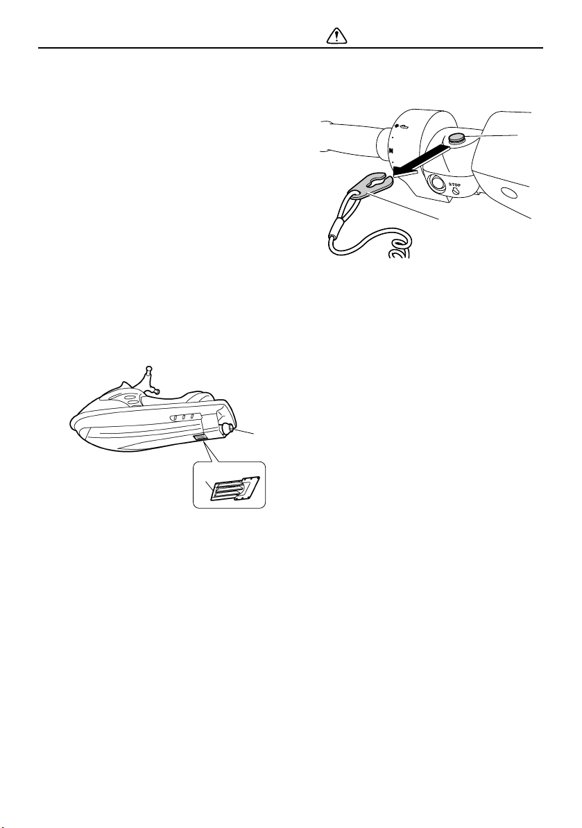
Engine shut-off switch “ ”
The engine shut-off switch automatically
stops the engine when the clip, on the end of
the engine shut-off cord (lanyard), is removed
from the switch, such as if the operator falls
off the watercraft.
Insert the clip under the engine shut-off
switch before starting the engine.
vent accidental starting or unauthorized operation by children or others.
EJU36287
Start switch “ ”
ECJ01311
Do not run the engine over 4000 r/min on
land. Also, do not run the engine for more
than 15 seconds without supplying water,
otherwise the engine could overheat.
The start switch (green button) starts the engine when the switch is pushed.
Release the start switch as soon as the engine starts to run. If the engine does not start
in 5 seconds, release the start switch, wait 15
seconds, and then try again. NOTICE: Never
push the start switch while the engine is
running. Do not operate the start switch
for more than 5 seconds, otherwise the
battery will be discharged and the engine
1 Engine shut-off switch
2 Clip
3 Engine shut-off cord (lanyard)
When the engine is not running, remove the
clip from the engine shut-off switch to pre-
27
Page 34

Control function operation
1
1
1
2
will not start. Also, the starter motor could
be damaged.
1 Start switch
[ECJ01041]
The engine will not start under any of the following conditions:
Lock mode of the Yamaha Security System
has been selected. (See page 26 for
Yamaha Security System setting procedures.)
Clip is removed from the engine shut-off
switch.
Throttle lever is squeezed.
EJU31212
Throttle lever
The throttle lever increases the engine speed
when the lever is squeezed.
1 Throttle lever
The throttle lever returns automatically to its
fully closed (idle) position when released.
EJU31262
Steering system
By turning the handlebars in the direction you
wish to travel, the angle of the jet thrust nozzle is changed, and the direction of the watercraft is changed accordingly.
1 Handlebar
2 Jet thrust nozzle
Since the strength of the jet thrust determines
the speed and degree of a turn, throttle must
always be applied when attempting a turn,
except at trolling speed.
This model is equipped with the Yamaha Engine Management System (YEMS) that includes an off-throttle steering (OTS) system.
It will activate at planing speeds should you
attempt to steer the watercraft after releasing
the throttle lever. The OTS system assists in
turning by continuing to supply some thrust
while the watercraft is decelerating, but you
can turn more sharply if you apply throttle
while turning the handlebars. The OTS system does not function below planing speeds
or when the engine is off. Once the engine
slows down, the watercraft will no longer turn
28
Page 35

Control function operation
1
1
in response to handlebar input until you apply
throttle again or you reach trolling speed.
EJU37343
Telescopic steering system
The position of the handlebars can be adjusted up or down by operating the telescopic
lock lever.
The handlebars can be adjusted to three positions.
To adjust the handlebar position:
(1) Pull the telescopic lock lever up to disen-
gage the handlebar lock, and then move
the handlebars up or down to the desired
position. WARNING! Never pull the
lock lever during operation, otherwise
the handlebars may suddenly change
position, which may lead to an accident.
[EWJ01271]
the handlebars are securely locked in
place.
EJU41801
Cooling water pilot outlets
When the engine is running, some of the
cooling water that is circulated in the engine
is discharged from the cooling water pilot
outlets.
1 Telescopic lock lever
(2) Make sure that the telescopic lock lever
returns to its original position and that
1 Cooling water pilot outlet (port [left] side)
There are cooling water pilot outlets on the
port (left) and starboard (right) sides of the
watercraft. To check for proper operation of
the cooling system, make sure that water is
being discharged from the port (left) pilot outlet. If water is not being discharged from the
outlet, stop the engine and check the jet intake for clogging. (See page 92 for information on the jet intake.)
29
Page 36

Control function operation
TIP:
1
2
It will take about 60 seconds for the water
to reach the outlets after the engine is started.
Water discharge may not be constant
when the engine is running at idling speed.
If this occurs, apply a little throttle to make
sure that water discharges properly.
EJU40323
Water separator
The water separator prevents water from entering the fuel tank by collecting any water
that has entered the fuel tank breather hose if
the watercraft was capsized.
If water has collected in the water separator,
drain it by loosening the drain screw.
1 Water separator
2 Drain screw
To drain water from the water separator:
(1) Place a drain pan or dry cloth under the
water separator.
(2) Gradually loosen the drain screw to drain
the water. Catch the draining water in the
drain pan or soak it up with the dry cloth
so that it does not spill into the engine
compartment. If any water spills into the
watercraft, be sure to wipe it up with a
dry cloth.
(3) Securely tighten the drain screw until it
stops.
30
Page 37

Watercraft operation
WARNING
TIP:
3
2
1
1
2
3
EJU40013
Watercraft operation functions
EJU37183
Reverse system
EWJ01231
Do not use the reverse function to slow
down or stop the watercraft as it could
cause you to lose control, be ejected, or
impact the handlebars.
Make sure that there are no obstacles or
people behind you before shifting into
reverse.
Do not touch the reverse gate while the
shift lever is being operated, otherwise
you could be pinched.
When the shift lever is moved to the reverse
position, the reverse gate lowers and deflects
the water jet being discharged from the jet
thrust nozzle. This allows the watercraft to
move in reverse.
To shift into reverse:
(1) Release the throttle lever and let the en-
gine speed return to idle.
(2) Pull the shift lever rearward until it stops
in the reverse position. The reverse gate
will lower and the watercraft will start
moving in reverse at trolling speed.
1 Shift lever
2 Reverse position
3 Forward position
1 Reverse gate
2 Forward position
3 Reverse position
This model is equipped with a function which
limits the engine speed in reverse.
To shift into forward:
(1) Release the throttle lever and let the en-
gine speed return to idle.
(2) Push the shift lever forward until it stops
in the forward position. The reverse gate
will rise and the watercraft will start moving forward at trolling speed.
EJU42650
Quick Shift Trim System (Q.S.T.S.)
The Q.S.T.S. selector is integrated with the
left handlebar grip and is operated to change
31
Page 38

Watercraft operation
TIP:
(c)
(d)
(a)
(b)
(b)
(a)
(d)
(c)
1
(d)
(c)
(b)
N
(a)
the vertical angle of the jet thrust nozzle,
which adjusts the trim angle of the watercraft.
There are 5 positions: neutral, 2 bow-down
positions (a) and (b), and 2 bow-up positions
(c) and (d).
The watercraft performance characteristics
according to the trim angle change depending on the operating conditions.
1 Q.S.T.S. selector
Bow-down positions (a) and (b)
The bow will go down, causing the trim angle
to decrease.
Vertical movement of the bow will be reduced
and the watercraft will get up on plane more
quickly when accelerating.
Bow-up positions (c) and (d)
The bow will go up, causing the trim angle to
increase.
There is less water resistance, therefore,
straight-ahead acceleration is enhanced.
32
To change the trim angle:
(1) Reduce engine speed to less than 3000
r/min.
(2) Squeeze the Q.S.T.S. selector lock lever,
and then turn the Q.S.T.S. selector to the
desired position. NOTICE: Do not turn
the Q.S.T.S. selector while operating
the watercraft at an engine speed of
Page 39

Watercraft operation
TIP:
3000 r/min or more, otherwise damage could occur to the Q.S.T.S.
1 Q.S.T.S. selector
2 Q.S.T.S. selector lock lever
[ECJ00014]
(3) Release the lock lever, and then make
sure that the Q.S.T.S. selector is securely
locked in place.
EJU40001
Watercraft operation modes
EJU42760
Low RPM Mode
The Low RPM Mode is a function that limits
the maximum engine speed to approximately
60% of the maximum engine speed in the
normal mode.
The Low RPM Mode can only be activated
and deactivated by operating the remote
control transmitter that is included with this
watercraft. (See page 25 for information on
the remote control transmitter.)
1 Remote control transmitter
The Low RPM Mode can only be activated
when the engine is stopped in the unlock
mode of the Yamaha Security System.
Activating and deactivating the Low RPM
Mode
Activation of the Low RPM Mode will be confirmed by the number of beeps when the remote control transmitter is operated, and by
the “L-MODE” indicator light of the dual analog meter unit. (See page 35 for information
on the dual analog meter unit.)
33
Page 40

Watercraft operation
TIP:
TIP:
L-Mode
1
2
Number of
beeps
Low RPM Mode
operation
Activated
Deactivated Goes off
“L-
MODE”
indicator
light
Comes
on
If the remote control transmitter is operated
while the dual analog meter unit is in the
standby state, the unit will perform the initial
operation, and then the setting is selected.
To activate the Low RPM Mode:
Push the “L-Mode” (unlock) button on the remote control transmitter for more than 4 seconds. Once the beeper sounds three times
and the “UNLOCK” indicator light blinks
three times, then comes on, the “L-MODE”
indicator light comes on and the Low RPM
Mode is activated.
If the Low RPM Mode is activated immediately after the information display turns off, the
“L-MODE” indicator light will not come on.
The “L-MODE” indicator light will come on
when the engine is started.
onds. Once the beeper sounds two times and
the “UNLOCK” indicator light blinks two
times, then comes on, the “L-MODE” indicator light goes off and the Low RPM Mode is
deactivated. When the Low RPM Mode is deactivated, the watercraft returns to the normal operation mode.
1 “L-Mode” (unlock) button
2 “L-MODE” indicator light
To deactivate the Low RPM Mode:
Push the “L-Mode” (unlock) button on the remote control transmitter for more than 4 sec-
34
Page 41

Instrument operation
TIP:
123
7654
EJU37433
Dual analog meter unit
The dual analog meter unit displays various
watercraft information.
1 Speedometer
2 Information display
3 Tachometer
4 “Hour Volt” button
5 “UNLOCK” indicator light
6 “L-MODE” indicator light
7 “WARNING” indicator light
Dual analog meter unit initial operation
When the dual analog meter unit is activated,
the speedometer and tachometer make one
sweep, all of the display segments and indicator lights come on. After 2 seconds, the
“WARNING” indicator light and the warning
indicators in the information display go off,
and then the unit starts to operate normally.
EJU37444
Speedometer
The speedometer shows the watercraft
speed against water.
The small inner numbers on the meter show
the watercraft speed in kilometers per hour
“km/h” and the large outer numbers show the
speed in miles per hour “mph”.
EJU37245
Tachometer
The tachometer shows the engine speed.
The numbers on the meter show the engine
speed × 1000 rpm (r/min).
The “UNLOCK” indicator light will go off
when the engine is started.
Dual analog meter unit standby state
If the dual analog meter unit does not receive
any operation input within 25 seconds after
the engine stops, the unit will turn off and enter a standby state. When the engine is started again, the displays return to their state
before the unit turned off, and then the unit
starts to operate normally.
35
Page 42

Instrument operation
TIP:
TIP:
1 2 3 4 5
6
1
1
2
EJU35027
Information display
The information display shows watercraft operating conditions.
1 Fuel level meter
2 Fuel indicator
3 Engine overheat warning indicator
4 Check engine warning indicator
5 Oil pressure warning indicator
6 Hour meter/voltmeter
EJU37265
Hour meter/voltmeter
The hour meter/voltmeter has both an hour
meter function and a voltmeter function. By
switching the meter, it can be used as either
an hour meter or a voltmeter.
The hour meter is selected at the Yamaha
factory.
Hour meter
The hour meter shows the total number of
hours that the engine has been running since
the watercraft was new.
The elapsed time will be kept even if the battery terminals have been disconnected.
To switch to the hour meter from the voltmeter:
Push the “Hour Volt” button for at least 1 second. The display switches to the hour meter
from the voltmeter.
1 “Hour Volt” button
2 Hour meter
Voltmeter
The voltmeter shows the battery voltage.
When the battery voltage is normal, the voltmeter displays approximately 12 volts.
If the battery voltage has dropped significantly, “LO” is displayed on the voltmeter. If the
battery voltage has risen significantly, “HI” is
displayed. If “LO” or “HI” is displayed, immediately return to shore and have a Yamaha
dealer service the watercraft.
1 Hour meter/voltmeter
36
Page 43

Instrument operation
TIP:
TIP:
1
2
1
To switch to the voltmeter from the hour meter:
Push the “Hour Volt” button for at least 1 second. The display switches to the voltmeter
from the hour meter.
1 “Hour Volt” button
2 Voltm et er
EJU37272
Fuel level meter
The fuel level meter shows the amount of fuel
remaining in the fuel tank. The amount of remaining fuel is shown using four display segments, which disappear one at a time as the
fuel level decreases.
The accuracy of the fuel level meter varies
depending on the operating conditions. Use
this function as a reference only.
EJU37285
Fuel level warning
If the fuel remaining in the fuel tank drops to
about 18 L (4.8 US gal, 4.0 Imp.gal), the lowest fuel level segment, the fuel indicator, and
the “WARNING” indicator light blink, and the
buzzer sounds intermittently.
If the fuel level warning is activated, refill the
fuel tank as soon as possible. (See page 47
for information on filling the fuel tank.)
After the fuel tank is refilled, the warning signals will be cleared when the engine is restarted.
Push the “Hour Volt” button to stop the buzzer.
EJU37294
Oil pressure warning
If the oil pressure drops significantly, the oil
pressure warning indicator and the “WARNING” indicator light blink, and the buzzer
1 Fuel level meter
37
Page 44

Instrument operation
TIP:
TIP:
sounds intermittently. At the same time, the
maximum engine speed is limited.
If the oil pressure warning is activated, immediately reduce the engine speed, return to
shore, and then check the engine oil level.
(See page 49 for information on checking the
engine oil level.) If the oil level is sufficient,
have a Yamaha dealer check the watercraft.
Push the “Hour Volt” button to stop the buzzer.
EJU37304
Engine overheat warning
If the engine temperature rises significantly,
the engine overheat warning indicator and
the “WARNING” indicator light blink, and the
buzzer sounds intermittently. Then, the engine overheat warning indicator and the
“WARNING” indicator light stop blinking and
remain on, and the buzzer sounds continuously. At the same time, the maximum engine
speed is limited.
If the engine overheat warning is activated,
immediately reduce the engine speed, return
to shore, and then make sure that water is
being discharged from the port (left) cooling
water pilot outlet while the engine is running.
If there is no discharge of water, stop the engine, and then check the jet intake for clogging. (See page 92 for information on the jet
intake.) NOTICE: If you cannot locate and
correct the cause of the overheating, consult a Yamaha dealer. Continuing to operate at higher speeds could result in severe
engine damage.
[ECJ00042]
Push the “Hour Volt” button to stop the buzzer.
EJU37313
Check engine warning
If a sensor malfunction or a short circuit is detected, the check engine warning indicator
and the “WARNING” indicator light blink, and
the buzzer sounds intermittently.
38
Page 45

If the check engine warning is activated, im-
TIP:
mediately reduce the engine speed, return to
shore, and have a Yamaha dealer check the
engine.
Push the “Hour Volt” button to stop the buzzer.
Instrument operation
39
Page 46

Equipment operation
1
1
EJU40334
Equipment
EJU42203
Seats
The front and rear seats are removable.
Remove the seats to access the engine compartment and removable watertight storage
compartment.
To remove the rear seat:
(1) Pull the rear seat latch up, and then lift up
the rear of the seat.
1 Seat latch
(2) Pull the seat rearward and remove it.
To install the rear seat:
(1) Insert the projections on the front of the
seat into the stays on the deck.
(2) Push the rear of the seat down to secure-
ly lock it in place.
To remove the front seat:
(1) Remove the rear seat.
(2) Pull the front seat latch up, and then lift
up the rear of the seat.
1 Seat latch
40
Page 47

Equipment operation
1
(3) Pull the seat rearward and remove it.
To install the front seat:
(1) Insert the projection on the front of the
seat into the stay on the deck.
(2) Push the rear of the seat down to secure-
ly lock it in place.
EJU37382
Reboarding grip
The reboarding grip is used when boarding
the watercraft from the water.
1 Reboarding grip
EJU34865
Reboarding step
The reboarding step is used to assist in reboarding the watercraft from the water.
When boarding the watercraft, push the reboarding step down until it stops. The step
returns automatically to its original position
when released. WARNING! Do not use the
reboarding step to lift the watercraft. The
reboarding step is not designed to support
the watercraft’s weight. If the reboarding
(3) Securely install the rear seat in its original
position.
41
Page 48

Equipment operation
NOTICE
1
1
1
step breaks, the watercraft could fall,
which could result in severe injury.
1 Reboarding step
ECJ00743
[EWJ01212]
towing it in an emergency. (See page 95 for
information on towing the watercraft.)
1 Bow eye
EJU34882
Stern eyes
The stern eyes are used to attach a rope to
the watercraft when transporting or mooring
it.
Use the reboarding step only to board the
watercraft in the water. Do not use the reboarding step for any other purpose. The
watercraft can be damaged.
EJU34873
Bow eye
The bow eye is used to attach a rope to the
watercraft when transporting, mooring, or
42
1 Stern eye
EJU35147
Storage compartments
This watercraft is equipped with the following
storage compartments.
Only the securely closed watertight storage
compartment is waterproof. If you carry objects that must be kept dry, put them in a waterproof bag.
Make sure that the storage compartments
are closed securely before operating the watercraft.
Page 49

Equipment operation
1
1
1
EJU37332
Bow storage compartment
The bow storage compartment is located under the hood.
To open the bow storage compartment:
Push the hood latch, and then lift up the rear
of the hood.
1 Hood latch
To close the bow storage compartment:
Push the rear of the hood down to securely
lock it in place.
To drain water from the bow storage compartment:
(1) Remove the drain plug on the bottom of
the storage compartment to drain the
water into the engine compartment.
1 Bow storage compartment
Bow storage compartment:
Capacity:
68.4 L (18.1 US gal, 15.0 Imp.gal)
Load limit:
5.0 kg (11 lb)
1 Drain plug
(2) Securely install the drain plug in its origi-
nal position.
EJU31757
Glove compartment
The glove compartment is located in front of
the seat.
43
Page 50

Equipment operation
1
1
1
1
To open the glove compartment:
Slide the glove compartment latch toward
you, and then lift up the lid.
1 Glove compartment latch
1 Glove compartment
Glove compartment:
Capacity:
3.5 L (0.9 US gal, 0.8 Imp.gal)
Load limit:
1.0 kg (2 lb)
To close the glove compartment:
Push the lid down to securely lock it in place.
To drain water from the glove compartment:
(1) Remove the beverage holder.
1 Beverage holder
(2) Remove the drain plug on the bottom of
the glove compartment to drain the water.
1 Drain plug
(3) Securely install the drain plug in its origi-
nal position.
44
Page 51

Equipment operation
1
1
1
(4) Securely install the beverage holder in its
original position.
EJU41422
Beverage holder
The beverage holder is located in the glove
compartment. (See page 43 for information
on the glove compartment.)
The beverage holder is removable.
1 Beverage holder
Do not place any items in the beverage holder while riding. Otherwise, the items may fall
out of the beverage holder.
EJU37235
Removable watertight storage compartment
The removable watertight storage compartment is located under the rear seat.
The compartment is watertight when the cap
is closed securely.
To open the removable watertight storage
compartment:
(1) Remove the rear seat. (See page 40 for
seat removal and installation procedures.)
(2) Loosen the cap and remove it.
1 Cap
1 Removable watertight storage compart-
ment
Removable watertight storage compartment:
Capacity:
8.7 L (2.3 US gal, 1.9 Imp.gal)
Load limit:
3.0 kg (7 lb)
To close the removable watertight storage
compartment:
(1) Securely install the cap by tightening it
until it stops.
(2) Securely install the rear seat in its original
position.
EJU41283
Fire extinguisher holder and cover
The fire extinguisher holder and cover are located in the bow storage compartment.
45
Page 52

Equipment operation
1
12
To use the fire extinguisher holder and cover:
(1) Push the hood latch, and then lift up the
rear of the hood.
1 Hood latch
(2) Unhook the band and remove the fire ex-
tinguisher cover.
hood is securely closed before using the
watercraft.
1 Band
2 Fire extinguisher holder and cover
(3) Place the fire extinguisher in the holder,
and then place the cover over the fire extinguisher.
(4) Securely fasten the cover and the fire ex-
tinguisher with the band.
(5) Push the rear of the hood down to se-
curely lock it in place. Make sure that the
46
Page 53

Operation and handling requirements
WARNING
NOTICE
EJU31823
Fuel requirements
EJU41294
Fuel
EWJ00283
Gasoline and gasoline vapors are ex-
tremely flammable. To avoid fires and
explosions and to reduce the risk of injury when refueling, follow these instructions.
Gasoline is poisonous and can cause in-
jury or death. Handle gasoline with care.
Never siphon gasoline by mouth. If you
should swallow some gasoline, inhale a
lot of gasoline vapor, or get some gasoline in your eyes, see your doctor immediately. If gasoline spills on your skin,
wash with soap and water. If gasoline
spills on your clothing, change your
clothes.
ECJ01870
Do not use leaded gasoline. Leaded
gasoline can seriously damage the engine.
Avoid getting water and contaminants in
the fuel tank. Contaminated fuel can
cause poor performance and engine
damage. Use only fresh gasoline that
has been stored in clean containers.
Use only gasoline with a minimum pump
octane number of 91 or a minimum research octane number of 95. Low-octane gasoline can seriously damage the
engine.
knocking (or pinging) occurs, use a gasoline
of a different brand.
Recommended fuel:
Premium unleaded gasoline with a
minimum octane rating of
91
(Pump octane number) = (R + M)/2
95 (Research octane number)
Gasohol
There are two types of gasohol: gasohol containing ethanol and that containing methanol.
Gasohol containing ethanol can be used if
ethanol content does not exceed 10% and
the fuel meets the minimum octane ratings.
E-85 is a fuel blend containing 85% ethanol
and therefore must not be used in this watercraft. All ethanol blends containing more than
10% ethanol can cause fuel system damage
or engine performance problems.
Yamaha does not recommend gasohol containing methanol because it can cause fuel
system damage and engine performance
problems.
To fill the fuel tank:
(1) Before refueling, stop the engine. Do not
stand or sit on the watercraft. Never refuel while smoking, or while in the vicinity
of sparks, open flames, or other sources
of ignition.
(2) Place the watercraft in a well-ventilated
area and in a horizontal position.
(3) Remove the seats, and then check the
fuel level. (See page 40 for seat removal
and installation procedures.)
Your Yamaha engine has been designed to
use premium unleaded gasoline with a pump
octane number [(R+M)/2] of 91 or higher, or a
research octane number of 95 or higher. If
47
Page 54

Operation and handling requirements
1
1
1
2
1
2
(4) Push the hood latch, and then lift up the
rear of the hood.
1 Hood latch
(5) Loosen the fuel filler cap and remove it.
1 Fuel filler cap
(6) Slowly add fuel to the fuel tank.
of the fuel tank. Do not overfill the fuel
tank. Because fuel expands when it
heats up, heat from the engine or the sun
can cause fuel to spill out of the fuel tank.
Do not leave the watercraft with a full
tank in direct sunlight.
1 Top of the fuel tank
2 Approximately 50 mm (2 in) from top of the
fuel tank
Fuel tank capacity:
70 L (18.5 US gal, 15.4 Imp.gal)
(7) Stop filling when the fuel level reaches
approximately 50 mm (2 in) from the top
48
1 Top of the fuel tank
2 Approximately 50 mm (2 in) from top of the
fuel tank
(8) Wipe up any spilled fuel immediately with
a dry cloth.
(9) Securely install the fuel filler cap by tight-
ening it until it clicks.
(10) Push the rear of the hood down to se-
curely lock it in place. Make sure that the
Page 55

Operation and handling requirements
NOTICE
TIP:
WARNING
NOTICE
fuel filler cap and the hood are securely
closed before using the watercraft.
(11) Securely install the seats in their original
positions.
EJU40291
Engine oil requirements
EJU41513
Engine oil
ECJ00282
Use only 4-stroke engine oil. Usage of 2stroke engine oil could result in severe engine damage.
Recommended engine oil type:
SAE 10W-30, 10W-40, 20W-40,
20W-50
Recommended engine oil grade:
API SE,SF,SG,SH,SJ,SL
When the engine is operated at high speeds,
some engine oil may be consumed. Be sure
to check the engine oil level.
Checking the engine oil level
EWJ00341
Engine oil is extremely hot immediately after the engine is turned off. Coming in contact with or getting any engine oil on your
clothes could result in burns.
ECJ01002
Make sure that debris and water do not
enter the oil filler hole. Debris and water in
the engine oil can cause serious engine
damage.
To check the engine oil level:
(1) Place the watercraft in a precisely level
position on land with the engine
stopped. If the engine was running, allow
the engine oil to settle by waiting 5 minutes or more before checking the oil level.
(2) Remove the seats. (See page 40 for seat
removal and installation procedures.)
49
Page 56

Operation and handling requirements
TIP:
1
1
2
1
(3) Remove the dipstick and wipe it clean.
1 Dipstick
(4) Insert the dipstick back into the dipstick
tube completely. Remove the dipstick
again and make sure that the engine oil
level is between the minimum and maximum level marks.
1 Maximum level mark
2 Minimum level mark
(5) If the engine oil level is significantly
above the maximum level mark, consult
a Yamaha dealer. If the engine oil level is
below the minimum level mark, add engine oil.
(6) Loosen the engine oil filler cap and re-
move it.
1 Engine oil filler cap
(7) Slowly add engine oil.
The difference between the minimum and
maximum level marks on the dipstick is equal
to approximately 1 L (1.06 US qt, 0.88 Imp.qt)
of engine oil.
(8) Wait approximately 5 minutes to allow
the engine oil to settle, and then check
the engine oil level again.
(9) Repeat steps 3–8 until the engine oil is at
the proper level.
(10) Securely install the engine oil filler cap by
tightening it until it stops.
(11) Securely install the seats in their original
positions.
50
Page 57

Operation and handling requirements
NOTICE
1
1
EJU40022
Draining the bilge water
ECJ01302
Do not run the engine at full throttle when
bilge water remains in the engine compartment. The bilge water can splash into
the engine, which can result in severe
damage.
EJU40036
Draining the bilge water on land
To drain the bilge water on land:
(1) Loosen the stern drain plugs and remove
them.
1 Stern drain plug
(2) Raise the bow of the watercraft, such as
by placing the watercraft on a slope, to
drain the bilge water from the engine
compartment.
(3) After the bilge water has drained from the
stern drain plug holes, wipe up any remaining moisture in the engine compartment with a dry cloth.
(4) Securely install the stern drain plugs by
tightening them until they stop. NOTICE:
Before installing the stern drain plugs,
clean the drain plug threads and the
O-rings on the plugs to remove any
foreign materials, such as dirt or sand.
Otherwise, the stern drain plugs could
be damaged, allowing water to enter
the engine compartment. Check the
O-rings on the stern drain plugs and
make sure that the plugs are tightened
securely before launching the watercraft. Otherwise, water may flood the
engine compartment and cause the
watercraft to submerge.
1 O-ring
EJU40044
[ECJ00363]
Draining the bilge water on water
A small quantity of bilge water will remain in
the engine compartment even after the bilge
water is drained on water. To completely
drain the bilge water, remove the watercraft
from the water and drain the bilge water on
land.
Jet vacuum bilge draining system
While the watercraft is operating, bilge water
in the engine compartment is drawn in by the
vacuum that is generated in the jet pump and
discharged from the watercraft through the
jet thrust nozzle.
To drain the bilge water on water:
Operate the watercraft as straight as possible
and above planing speed for at least 2 minutes. NOTICE: Do not run the engine at full
throttle for at least 1 minute after the engine has been restarted. Bilge water in the
engine compartment can splash into the
51
Page 58

Operation and handling requirements
TIP:
1
engine, which can result in severe damage.
[ECJ00554]
Electric bilge draining system
Bilge water in the engine compartment is
drawn in by the operation of the electric bilge
pump and discharged from the watercraft.
To check for proper operation of the electric
bilge draining system, make sure that bilge
water is being discharged from the electric
bilge pilot outlet.
EJU33465
Transporting on a trailer
When transporting the watercraft on a trailer,
secure the tie downs to the trailer through the
bow eye and stern eyes. NOTICE: Do not at-
tach ropes or tie downs to any part of the
watercraft other than the bow eye and
stern eyes to secure the watercraft to the
trailer. Otherwise, the watercraft may be
damaged. Wrap the ropes or tie downs
with towels or rags where they touch the
body of the watercraft to avoid scratches
or damage. Do not transport the watercraft with the shift lever in the reverse position. Otherwise, the reverse gate may hit
an obstacle, which could cause damage.
[ECJ00645]
1 Electric bilge pilot outlet
To drain the bilge water:
Start the engine to operate the electric bilge
pump.
The electric bilge pump continues to operate
for a short time after the engine stops.
52
Page 59

EJU42690
NOTICE
Engine break-in
ECJ00432
Failure to perform the engine break-in
could result in reduced engine life or even
severe engine damage.
The engine break-in is essential to allow the
various components of the engine to wear
and polish themselves to the correct operating clearances. This ensures proper performance and promotes longer component life.
To perform the engine break-in:
(1) Check the engine oil level. (See page 49
for information on checking the engine
oil level.)
(2) Launch the watercraft and start the en-
gine. (See page 66 for information on
starting the engine.)
(3) For the first 5 minutes, operate with the
engine speed at 2000 r/min.
(4) For the next 90 minutes, operate with the
engine speed below 5000 r/min.
After the engine break-in is complete, the watercraft can be operated normally.
First-time operation
53
Page 60

Pre-operation checks
WARNING
EJU31982
EWJ00412
Failure to inspect or maintain the watercraft properly increases the possibility of an accident or damage to the watercraft. Do not operate the watercraft if you find any problem. If a problem cannot be corrected by the procedures provided in this manual, have
the watercraft inspected by a Yamaha dealer.
EJU41234
Pre-operation checklist
Before using this watercraft, be sure to perform the checks in the following checklist.
ITEM ROUTINE PAGE
PRE-LAUNCH CHECKS
Engine compartment
Fuel system
Water separator Check the water separator for water. 56
Engine unit Check the exterior of the engine unit for damage. 57
Engine oil level Check the engine oil level. 57
Bilge water Check the engine compartment for bilge water. 57
Battery Check the battery connections and electrolyte level. 57
Steering system Check the steering system for proper operation. 58
Telescopic steering system
Q.S.T.S.
Reverse system Check the reverse system for proper operation. 60
Throttle lever
Remote control transmitter
Engine shut-off cord (lanyard)
Switches
Storage compartments
Fire extinguisher holder,
cover, and band
Fire extinguisher Check the condition of the fire extinguisher. 62
Ventilate the engine compartment.
Check inside the engine compartment for damage.
Check the fuel system for leakage.
Check the fuel level in the fuel tank.
Check the telescopic steering system for proper operation and check that the handlebars are securely
locked in place.
Check the Q.S.T.S. for proper operation and check
that the Q.S.T.S. selector is securely locked in
place.
Check the throttle lever for proper operation.
Check the throttle lever free play.
Check the remote control transmitter for proper operation.
Check the engine shut-off cord (lanyard) for damage.
Check the start switch, engine stop switch, and engine shut-off switch for proper operation.
Check the storage compartments for damage and
water.
Check the fire extinguisher holder, cover, and band
for damage.
56
56
59
59
60
61
61
61
62
62
54
Page 61

Pre-operation checks
TIP:
ITEM ROUTINE PAGE
Safety equipment
Hull and deck Check the hull and deck for damage. 62
Jet intake Check the jet intake for damage and clogging. 63
Jet thrust nozzle and reverse gate
Stern drain plugs
Hood Check that the hood is securely closed. 63
Front and rear seats Check that the seats are securely installed. 40
POST-LAUNCH CHECKS
Cooling water pilot outlet
Dual analog meter unit
Engine idling speed Check the engine idling speed. 64
To ensure safety and reliability, pre-operation checks should be made each time the watercraft is used.
Check that safety equipment meeting the applicable regulations is on board.
Check the jet thrust nozzle and reverse gate for
damage.
Check the stern drain plugs for damage and foreign
material and check that they are securely installed.
Check that water is discharged from the port (left)
cooling water pilot outlet while the engine is running.
Check the dual analog meter unit for proper operation.
62
63
63
64
64
55
Page 62

Pre-operation checks
WARNING
WARNING
EJU32282
Pre-operation check points
EJU42383
Pre-launch checks
Perform the pre-launch checks in the pre-operation checklist while the watercraft is on
land.
To perform the pre-launch checks:
(1) Remove the seats and removable water-
tight storage compartment. (See page 40
for seat removal and installation proce-
dures and page 45 for information on the
removable watertight storage compart-
ment.)
(2) Perform the checks and make sure that
there are no malfunctioning items or oth-
er problems.
(3) After completing these checks, securely
install the removable watertight storage
compartment and seats in their original
positions.
EJU32334
Engine compartment check
EWJ00462
Failure to ventilate the engine compartment could result in a fire or explosion. Do
not start the engine if there is a fuel leak.
Ventilate the engine compartment. Leave the
engine compartment open for a few minutes
to allow any fuel vapors to escape.
Make sure that there is no damage inside the
engine compartment.
EJU34215
Fuel system checks
EWJ00382
Leaking fuel can result in fire or explosion.
Check for fuel leakage regularly.
If any fuel leakage is found, the fuel sys-
tem must be repaired by a qualified mechanic. Improper repairs can make the
watercraft unsafe to operate.
Make sure that there is no damage, leakage,
or other problem in the fuel system.
Check:
Fuel filler cap and seal for damage
Fuel tank for damage and leakage
Fuel hoses and joints for damage and leak-
age
Fuel tank breather hose for damage and
leakage
EJU36875
Fuel level check
Check the fuel level in the fuel tank.
Add fuel if necessary. (See page 47 for information on filling the fuel tank.)
EJU32424
Water separator check
Make sure that no water has collected in the
water separator. If water has collected in the
56
Page 63

Pre-operation checks
1
1
1
2
water separator, drain it. (See page 30 for information on draining the water separator.)
1 Water separator
EJU40182
Engine unit check
Check the exterior of the engine unit for damage or other problem.
EJU36886
Engine oil level check
Make sure that the engine oil level is between
the minimum and maximum level marks on
the dipstick. (See page 49 for information on
checking the engine oil level.)
1 Dipstick
1 Maximum level mark
2 Minimum level mark
EJU32456
Bilge water check
Make sure that no bilge water has collected in
the engine compartment. If bilge water has
collected in the engine compartment, drain it.
(See page 51 for information on draining the
bilge water.)
EJU32485
Battery checks
Make sure that the battery terminals and
breather hose are not damaged and that the
battery leads and breather hose are connected properly. WARNING! Fire or explosion
could result if the breather hose is dam-
57
Page 64

Pre-operation checks
1
2
3
aged, obstructed, or not connected properly.
[EWJ00452]
1 Negative (–) battery terminal: Black lead
2 Positive (+) battery terminal: Red lead
3 Breather hose
Make sure that the electrolyte level is between the minimum and maximum level
marks. WARNING! Never operate the wa-
tercraft if the battery does not have sufficient power to start the engine or if it
shows any other signs of decreased power. Loss of battery power may leave you
stranded.
[EWJ01241]
whole range, and that the free play is not excessive.
Turn the handlebars as far as possible to the
right and left to make sure that the jet thrust
nozzle moves as the handlebars are turned,
and that there is no difference between the
1 Maximum level mark
2 Minimum level mark
Make sure that the battery is securely held in
place.
EJU32614
Steering system checks
Turn the handlebars to the right and left several times to make sure that operation is
smooth and unrestricted throughout the
58
Page 65

Pre-operation checks
right and left fully turned positions of the jet
thrust nozzle.
locked in place. (See page 29 for telescopic
steering system operation procedures.)
EJU32645
Quick Shift Trim System (Q.S.T.S.) checks
Operate the Q.S.T.S. selector lock lever and
the Q.S.T.S. selector several times to make
sure that operation is smooth throughout the
whole range. Also, make sure that the jet
thrust nozzle moves as the Q.S.T.S. selector
is operated and that the Q.S.T.S. selector se-
Difference between fully turned positions of jet thrust nozzle (distances A
and B):
Maximum 5 mm (0.20 in)
EJU41321
Telescopic steering system checks
Operate the telescopic steering system several times to make sure that operation is
smooth throughout the whole range. Also,
make sure that the handlebars are securely
59
Page 66

Pre-operation checks
WARNING
1
curely locks in place. (See page 31 for
Q.S.T.S. operation procedures.)
EJU32635
Reverse system checks
EWJ00032
gate moves up and down according to the
operation of the shift lever and that the gate
makes contact with the stoppers. (See page
31 for reverse system operation.)
1 Stopper
EJU41433
Throttle lever checks
Operate the throttle lever several times to
make sure that operation is smooth throughout the whole range. Also, make sure that the
throttle lever returns automatically to its fully
closed (idle) position when released.
Do not touch the reverse gate while the
shift lever is being operated, otherwise
you could be pinched.
Operate the shift lever several times to make
sure that operation is smooth throughout the
whole range. Also, make sure that the reverse
60
Page 67

Pre-operation checks
NOTICE
1
1
Face the handlebars straight ahead with the
handlebars in the highest position and the
throttle lever in the fully closed (idle) position,
and then make sure that there is the proper
amount of throttle lever free play when the
throttle lever is in the fully closed (idle) position. (See page 29 for telescopic steering system operation procedures.)
1 Highest position with handlebars facing
straight ahead
EJU32664
Engine shut-off cord (lanyard) check
Make sure that the engine shut-off cord (lanyard) is not damaged. If the cord is damaged,
replace it. WARNING! Never try to repair
the engine shut-off cord (lanyard) or tie it
together. The engine shut-off cord (lanyard) may not pull free when the operator
falls off, allowing the watercraft to continue to run and cause an accident.
EJU32676
[EWJ01221]
Switch checks
ECJ01311
Do not run the engine over 4000 r/min on
land. Also, do not run the engine for more
than 15 seconds without supplying water,
otherwise the engine could overheat.
1 Throttle lever free play
Throttle lever free play:
2.0–5.0 mm (0.08–0.20 in)
EJU40113
Remote control transmitter check
Make sure that the remote control transmitter
operates properly. (See page 26 for Yamaha
Security System setting procedures and
page 33 for Low RPM Mode activation procedures.)
Check the start switch, the engine stop
switch, and the engine shut-off switch for
61
Page 68

Pre-operation checks
231
54
proper operation. (See pages 27 to 27 for information on operating each switch.)
1 Engine shut-off switch
2 Clip
3 Start switch
4 Engine stop switch
5 Engine shut-off cord (lanyard)
To check the operation of the switches:
(1) If the lock mode is selected for the
Yamaha Security System setting, select
the unlock mode. (See page 26 for
Yamaha Security System setting proce-
dures.)
(2) Push the start switch to make sure that
the engine starts.
(3) As soon as the engine starts running,
push the engine stop switch to make
sure that the engine stops immediately.
(4) Restart the engine, and then pull the en-
gine shut-off cord (lanyard) to remove
the clip from the engine shut-off switch
to make sure that the engine stops im-
mediately.
EJU40102
Storage compartment checks
Make sure that the storage compartments
are not damaged and that water has not collected in the compartments. (See page 42 for
information on the storage compartments.)
EJU41082
Fire extinguisher holder, cover, and band
checks
Make sure that the fire extinguisher holder,
cover, and band are not damaged and that
the cover is securely held in place using the
band. (See page 45 for information on the fire
extinguisher holder, cover, and band.)
EJU32544
Fire extinguisher check
Check that there is a full fire extinguisher on
board.
To check the fire extinguisher, see the instructions supplied by the fire extinguisher
manufacturer. Always keep the fire extinguisher secured in the holder with its cover in
place.
Always carry a fire extinguisher on board. A
fire extinguisher is not standard equipment
with this watercraft. If you do not have one,
contact a Yamaha dealer or a fire extinguisher dealer to obtain one meeting the proper
specifications.
EJU40122
Safety equipment check
Check that safety equipment meeting the applicable regulations is on board.
EJU32353
Hull and deck check
Check the hull and deck for damage or other
problem.
62
Page 69

Pre-operation checks
2
1
EJU32657
Jet intake checks
Make sure that the jet intake is not damaged
or clogged with weeds or debris. If the jet intake is clogged, clean it. (See page 92 for information on the jet intake.)
EJU43220
Jet thrust nozzle and reverse gate check
Check the jet thrust nozzle and reverse gate
for damage or other problem.
EJU32477
Stern drain plug checks
Loosen the stern drain plugs and remove
them, and then make sure that the plugs and
O-rings on the plugs are not damaged and
that there is no foreign material on the
threads or O-rings on the plugs. NOTICE:
Before installing the stern drain plugs,
clean the drain plug threads and the Orings on the plugs to remove any foreign
materials, such as dirt or sand. Otherwise,
the stern drain plugs could be damaged,
allowing water to enter the engine compartment. Check the O-rings on the stern
drain plugs and make sure that the plugs
are tightened securely before launching
the watercraft. Otherwise, water may
flood the engine compartment and cause
the watercraft to submerge.
[ECJ00363]
Securely install the stern drain plugs by tightening them until they stop.
1 Stern drain plug
2 O-ring
EJU41441
Hood check
Push down on the rear of the hood and make
sure that it is securely closed.
63
Page 70

Pre-operation checks
EJU40146
Post-launch checks
Perform the post-launch checks in the preoperation checklist while the watercraft is in
the water and the engine is running.
To perform the post-launch checks:
(1) Launch the watercraft. (See page 66 for
information on launching the watercraft.)
(2) Perform the checks and make sure that
there are no malfunctioning items or oth-
er problems.
EJU41811
Cooling water pilot outlet check
Make sure that water is discharged from the
port (left) cooling water pilot outlet while the
engine is running. (See page 29 for information on the cooling water pilot outlets.)
EJU41331
Engine idling speed check
Start the engine and warm it up. Use the tachometer in the dual analog meter unit to
make sure that the engine idling speed is not
significantly above or below the specified
range.
Engine idling speed:
1250 ±100 r/min
EJU37452
Dual analog meter unit check
Make sure that the dual analog meter unit operates properly. (See page 35 for information
on proper operation of the dual analog meter
unit.)
64
Page 71

Operation
WARNING
EJU32903
Operating your watercraft
EWJ00511
Before operating your watercraft, become
familiar with all of the controls. Consult a
Yamaha dealer about any control or func-
tion that you do not fully understand. Failure to understand how the controls work
could cause an accident or prevent you
from avoiding an accident.
EJU32943
Getting to know your watercraft
Operating your watercraft requires skills acquired through practice over a period of time.
Take the time to learn the basic techniques
well before attempting more difficult maneuvers.
Operating your new watercraft can be a very
enjoyable activity, providing you with hours of
pleasure. However, it is essential to familiarize yourself with the operation of the watercraft to achieve the skill level necessary to
enjoy riding safely.
Before operating this watercraft, read this
owner’s/operator’s manual, the Riding Practice Guide, the Riding Instruction card, and all
labels on the watercraft. Pay particular attention to the safety information beginning on
page 11. These materials should give you an
understanding of the watercraft and its operation.
Remember: This watercraft is designed to
carry the operator and 1 passenger. Never
exceed the maximum load limit or allow more
than 2 persons to ride the watercraft at any
time.
EJU36043
Learning to operate your watercraft
Before operating the watercraft, always perform the pre-operation checks listed on page
54. The short time spent checking the watercraft will reward you with added safety and
reliability.
Check local laws before operating your watercraft.
Operate defensively at safe speeds and keep
a safe distance away from people, objects,
and other watercraft. Select a wide area to
learn in, where there is good visibility and
light boat traffic.
Use the buddy system—operate with someone nearby. Scan constantly for people, objects, and other watercraft. Be alert for
conditions that limit your visibility or block
your vision of others.
You should grip the handlebars firmly and
keep both feet on the floor of the footwell. Do
not attempt to ride with a passenger until
your operating skills are fully developed.
Maximum load:
160 kg (353 lb)
Load is the total weight of cargo, operator, and passenger.
65
Page 72

Operation
WARNING
60 cm (2 ft)
EJU41341
Riding position
Operator riding position
The operator should grip the handlebars firmly with both hands and sit astride the seat
with both feet on the floor of the footwell.
Passenger riding position
The passenger should hold on firmly to the
operator and sit astride the seat with both
feet on the floor of the footwell. Never allow a
passenger to ride in front of the operator.
EJU36346
Starting the engine on water
EWJ01531
Do not apply throttle when anyone is at the
rear of the watercraft. Turn the engine off
or keep it at idle. Water and debris exiting
the jet thrust nozzle can cause severe injury.
To start the engine:
(1) If the lock mode is selected for the
Yamaha Security System setting, select
the unlock mode. (See page 26 for
Yamaha Security System setting procedures.)
(2) Move the watercraft to an area that is
free from weeds and debris, and has a
water depth of at least 60 cm (2 ft) from
the bottom of the watercraft. NOTICE:
Never run the engine in water that is
less than 60 cm (2 ft) deep from the
bottom of the watercraft, otherwise
pebbles or sand could be sucked into
the jet intake, causing impeller damage and engine overheating.
[ECJ00473]
EJU32803
Launching the watercraft
When launching the watercraft, make sure
that there are no obstacles around you.
If the watercraft is launched from a trailer,
someone should make sure that waves do
not push the watercraft into the trailer.
66
(3) Attach the engine shut-off cord (lanyard)
to your left wrist, and then attach the clip
to the engine shut-off switch. (See page
27 for information on operating the engine shut-off switch.) WARNING! Check
that the engine shut-off cord (lanyard)
Page 73

Operation
12
3
is attached correctly. If the engine
shut-off cord (lanyard) is not attached
correctly, it may not pull free when the
operator falls off, allowing the water-
craft to continue to run and cause an
accident.
1 Clip
2 Engine shut-off switch
3 Engine shut-off cord (lanyard)
[EWJ00582]
(4) With the throttle lever released, push the
start switch (green button) to start the
engine. (See page 27 for information on
operating the start switch.)
to avoid. A collision could result in severe
injury or death.
EJU32873
[EWJ00602]
Leaving the watercraft
If leaving the watercraft, remove the clip from
the engine shut-off switch to prevent accidental starting or unauthorized operation by
children or others.
EJU32863
Stopping the engine
Release the throttle lever, and then push the
engine stop switch (red button) to stop the
engine. WARNING! You need throttle to
steer. Shutting the engine off can cause
you to hit an obstacle you are attempting
EJU40222
Operating the watercraft
When the shift lever is in the forward position
and the engine is running, the watercraft will
move forward. The watercraft will move forward at trolling speed even if the throttle lever
is in the fully closed (idle) position. (See page
67
Page 74

Operation
WARNING
2
1
31 for information on operating the shift lever.)
1 Shift lever
2 Forward position
EJU33255
Turning the watercraft
EWJ00772
Water sucked in through the intake grate is
pressurized by the impeller in the jet pump.
As the pressurized water is expelled from the
pump through the jet thrust nozzle, it creates
thrust to move and steer the watercraft. The
higher the engine speed, the more thrust produced.
The amount of jet thrust, in addition to the position of the handlebars, determines how
sharply you turn.
A. More throttle produces higher thrust, so
the watercraft will turn more sharply.
B. Less throttle produces lower thrust, so
the watercraft will turn more gradually.
Do not release the throttle lever when
trying to steer away from objects—you
need throttle to steer. A collision could
result in severe injury or death.
When operating at higher speeds, make
gradual turns or slow down before turning. Sharp high-speed turns may cause
the watercraft to slide sideways or spin,
throwing the operator and passenger(s)
overboard, which could cause an injury.
Steering control depends on the combination
of handlebar position and the amount of
throttle.
68
C. Releasing the throttle lever completely
produces only minimum thrust. If you are
traveling at speeds above trolling, you
will have rapidly decreasing ability to
steer without throttle. You may still have
some turning ability immediately after releasing the throttle lever, but once the
Page 75

Operation
WARNING
125 m (410 ft)
engine slows down, the watercraft will no
longer respond to handlebar input until
you apply throttle again or you reach
trolling speed.
At trolling speed, the watercraft can be
turned gradually by handlebar position
alone using just the amount of thrust
available at idle.
D. If the engine is stopped while riding,
there is no thrust. The watercraft will go
straight even though the handlebars are
turned.
craft is decelerating, but you can turn more
sharply if you apply throttle while turning the
handlebars. The OTS system does not function below planing speeds or when the engine is off. Once the engine slows down, the
watercraft will no longer turn in response to
handlebar input until you apply throttle again
or you reach trolling speed.
EJU42660
Stopping the watercraft
The watercraft is not equipped with a separate braking system. It is stopped by water
resistance when the throttle lever is released.
From full speed, the watercraft comes to a
complete stop in approximately 125 m (410
ft) after the throttle lever is released or the engine is stopped, although this distance will
vary depending on many factors, including
gross weight, water surface conditions, and
wind direction. The watercraft slows down as
soon as the throttle lever is released, but will
coast for a distance before fully stopping. If
you are not sure you can stop in time before
hitting an obstacle, apply throttle and turn in
another direction.
You need throttle to steer.
This model is equipped with the Yamaha Engine Management System (YEMS) that includes an off-throttle steering (OTS) system.
It will activate at planing speeds should you
attempt to steer the watercraft after releasing
the throttle lever (see condition C above).
The OTS system assists in turning by continuing to supply some thrust while the water-
EWJ00745
Allow adequate stopping distance.
Take early action to avoid collisions. Re-
member, watercraft and other boats do
not have brakes.
69
Page 76

Operation
TIP:
WARNING
TIP:
1
2
60 cm (2 ft)
Operate defensively at safe speeds and
keep a safe distance away from people,
objects, and other watercraft to give you
time to stop.
Do not shut the engine off when slowing
down in case you need engine power to
steer away from a boat or other obstacle
that comes into your path.
Do not use the reverse function to slow
down or stop the watercraft as it could
cause you to lose control, be ejected, or
impact the handlebars.
EJU40372
Operating the watercraft in reverse
Pull the shift lever rearward to the reverse position. The watercraft will move in reverse.
(See page 31 for information on the reverse
system.)
Make sure that there are no obstacles or people behind you before shifting into reverse.
This model is equipped with a function which
limits the engine speed in reverse.
EJU41453
Boarding the watercraft
EWJ00622
Be sure the operator and passenger have
practiced boarding from the water while
still close to shore before riding. A person
who has made many unsuccessful attempts to get back on the watercraft may
become fatigued and suffer from exposure, increasing the risk of injury and
drowning.
Board the watercraft in water free from
weeds and debris and at least 60 cm (2 ft)
deep from the bottom of the watercraft.
NOTICE: Never run the engine in water
that is less than 60 cm (2 ft) deep from the
bottom of the watercraft, otherwise pebbles or sand could be sucked into the jet
intake, causing impeller damage and engine overheating.
[ECJ00473]
1 Shift lever
2 Reverse position
70
This watercraft is equipped with a reboarding
step, which can be lowered and used to assist in reboarding. (See page 41 for information on operating the reboarding step.)
Page 77

Operation
WARNING
EJU37464
Boarding alone
(1) From the rear of the watercraft, place
both hands on the boarding platform,
pull yourself up, and then grasp the re-
boarding grip with one hand.
(4) Grip the handlebars with both hands and
place both feet on the floor of the footwell.
(5) Look in all directions, start the engine,
and then start off slowly.
EJU33156
Boarding with a passenger
EWJ00651
Severe internal injuries can occur if water
is forced into body cavities as a result of
being near the jet thrust nozzle. Do not apply throttle until the passenger is seated
with both feet on the floor of the footwell
and is securely holding on to the operator.
(2) Pull yourself up to a kneeling position on
the boarding platform, and then move to
the seat and sit astride.
(3) Attach the engine shut-off cord (lanyard)
to your left wrist, and then attach the clip
to the engine shut-off switch.
The heavier the total weight of the operator
and passenger, the more difficult it will be to
balance the watercraft. Do not operate the
watercraft when the total weight exceeds 160
kg (353 lb) including any cargo.
71
Page 78

Operation
To board at a standstill:
(1) Board as noted in the previous section
“Boarding alone”.
(2) Attach the engine shut-off cord (lanyard)
to your left wrist, and then attach the clip
to the engine shut-off switch.
(3) Grip the handlebars with both hands and
place both feet on the floor of the foot-
well.
(4) Have the passenger move to the rear of
the watercraft.
the watercraft together with the passenger.
(6) Make sure that the passenger has their
feet on the floor of the footwell and is securely holding on to the operator.
(5) Have the passenger board using the
same procedure as the operator, place
their feet on the floor of the footwell, and
securely hold on to the operator. When
the passenger is boarding, try to balance
72
(7) Look in all directions, start the engine,
and then start off slowly.
Page 79

Operation
WARNING
To board when it is difficult to balance at a
standstill:
(1) Have the passenger steady the water-
craft, and then board as noted in the pre-
vious section “Boarding alone”.
(2) Grip the handlebars with both hands,
place both feet on the floor of the foot-
well, and balance there.
(3) Attach the engine shut-off cord (lanyard)
to your left wrist, and then attach the clip
to the engine shut-off switch.
(4) Look in all directions, and then start the
engine and operate at trolling speed.
(5) Have the passenger pull themselves up
onto the boarding platform into a kneel-
ing position and balance there. Look in
all directions, and then gradually acceler-
ate. Then, have the passenger crawl onto
the seat while maintaining their balance.
(6) Have the passenger sit astride the seat,
place their feet on the floor of the foot-
well, securely hold on to the operator,
and balance there.
(7) Make sure that the passenger has their
feet on the floor of the footwell and is securely holding on to the operator, and
then gradually increase the speed to balance the watercraft.
EJU33083
Starting off
EWJ00712
To avoid collisions:
Scan constantly for people, objects, and
other watercraft. Be alert for conditions
that limit your visibility or block your vision of others.
Operate defensively at safe speeds and
keep a safe distance away from people,
objects, and other watercraft.
Do not follow directly behind watercraft
or other boats. Do not go near others to
spray or splash them with water. Avoid
sharp turns or other maneuvers that
make it hard for others to avoid you or
understand where you are going. Avoid
areas with submerged objects or shallow water.
Take early action to avoid collisions. Re-
member, watercraft and other boats do
not have brakes. Do not release the
throttle lever when trying to steer away
73
Page 80

Operation
NOTICE
WARNING
from objects—you need throttle to
steer.
ECJ01341
Never run the engine in water that is less
than 60 cm (2 ft) deep from the bottom of
the watercraft, otherwise pebbles or sand
could be sucked into the jet intake, causing impeller damage and engine overheating.
EJU40233
Starting off from a trailer
(1) Launch the watercraft and move the shift
lever to the reverse position. (See page
31 for information on the reverse sys-
tem.)
(2) Attach the engine shut-off cord (lanyard)
to your left wrist, and then attach the clip
to the engine shut-off switch.
(3) Look in all directions, start the engine,
and then start off slowly.
EJU33114
Boarding and starting off from a dock
(1) Board the watercraft from the side.
(2) Attach the engine shut-off cord (lanyard)
to your left wrist, and then attach the clip
to the engine shut-off switch.
(3) Push the watercraft away from the dock,
grip the handlebars with both hands, and
place both feet on the floor of the footwell.
(4) Look in all directions, start the engine,
and then start off slowly.
EJU33236
Capsized watercraft
EWJ00672
Improper uprighting can cause injury.
Be sure to shut the engine off by pulling
on the engine shut-off cord (lanyard) to
remove the clip from the engine shut-off
switch.
Do not put your hands in the intake
grate.
If the watercraft capsizes, turn it over immediately.
To upright the watercraft:
(1) Remove the clip from the engine shut-off
switch.
(2) Swim to the rear of the watercraft. Turn
the watercraft over clockwise by pulling
on the ride plate with your left hand while
pushing down on the gunwale with your
right hand or foot.
If the port (left) side of the capsized watercraft is tilting up, push down on the
gunwale so that the port (left) side is
down before turning the watercraft
clockwise. NOTICE: Do not turn the
watercraft over counterclockwise,
74
Page 81

Operation
otherwise water can enter the engine,
which can result in severe damage.
[ECJ00542]
(3) Start the engine and operate the water-
craft at planing speed to drain the bilge
water from the engine compartment.
(See page 51 for information on draining
the bilge water. If the engine does not
start, see “Towing the watercraft” on
page 95 or “Submerged watercraft” on
page 95.) NOTICE: Do not run the en-
gine at full throttle for at least 1 minute
after the engine has been restarted.
Bilge water in the engine compart-
ment can splash into the engine,
which can result in severe damage.
[ECJ00554]
EJU42670
Beaching and docking the watercraft
To beach the watercraft:
(1) Make sure that there are no boats, swim-
mers, or obstacles near the beach.
(2) Release the throttle lever to reduce
speed about 125 m (410 ft) before you
reach the intended beaching area.
(3) Slowly approach the beach and stop the
engine just before reaching land.
WARNING! You need throttle to steer.
Shutting the engine off can cause you
to hit an obstacle you are attempting
to avoid. A collision could result in severe injury or death.
[EWJ00602] NOTICE:
Never run the engine in water that is
less than 60 cm (2 ft) deep from the
bottom of the watercraft, otherwise
pebbles or sand could be sucked into
the jet intake, causing impeller damage and engine overheating.
[ECJ00473]
(4 ) Get off the wate rcr aft and pull it u p on the
beach.
To dock the watercraft:
(1) Make sure that there are no boats, swim-
mers, or obstacles near the dock.
(2) Release the throttle lever to reduce
speed about 125 m (410 ft) away from
the dock.
(3) Slowly approach the dock and stop the
engine just before coming alongside it.
WARNING! You need throttle to steer.
Shutting the engine off can cause you
to hit an obstacle you are attempting
to avoid. A collision could result in se-
vere injury or death.
[EWJ00602]
(4) Come alongside the dock and get off the
watercraft.
EJU37194
Operating in weeded areas
Always avoid using your watercraft in areas
where weed growth is thick. If operating in
weeded areas is unavoidable, alternately
squeeze the throttle lever and relax your grip
on the throttle lever to vary the engine speed.
Weeds tend to become clogged more when
operating at a steady speed and at trolling
75
Page 82

Operation
NOTICE
speed. If weeds may have clogged the intake
area, clean the jet intake. (See page 92 for information on the jet intake.)
EJU40242
After removing the watercraft from
the water
ECJ01311
Do not run the engine over 4000 r/min on
land. Also, do not run the engine for more
than 15 seconds without supplying water,
otherwise the engine could overheat.
After operating and removing the watercraft
from the water, promptly discharge the remaining water from the cooling water passages.
To discharge water from the cooling water
passages:
(1) Make sure that the area around the wa-
tercraft is clear, and then start the engine.
(2) Discharge the remaining water out of the
cooling water passages by alternately
squeezing and releasing the throttle lever
quickly for 10 to 15 seconds.
(3) Stop the engine.
76
Page 83

Care and storage
WARNING
NOTICE
23
1
EJU37146
Post-operation care
EWJ00331
Always place the watercraft upright in a
horizontal position when storing it, otherwise fuel could leak out into the engine or
engine compartment, which could create
a fire hazard.
After using the watercraft, always take it out
of the water, clean it, and store it. Leaving the
watercraft in the water for extended periods
will accelerate the rate of normal deterioration of the jet pump and hull. Marine organisms and corrosion are some of the
conditions that can shorten the life of many
watercraft components.
EJU37566
Flushing the cooling water passages
ECJ01880
Do not run the engine over 4000 r/min on
land. Also, do not run the engine for
more than 15 seconds without supplying
water, otherwise the engine could overheat.
Flush the cooling water passages to
prevent them from clogging with salt,
sand, or dirt.
(1) Place the watercraft in a horizontal posi-
tion.
(2) Remove the seats and removable water-
tight storage compartment. (See page 40
for seat removal and installation procedures and page 45 for information on the
removable watertight storage compartment.)
(3) Connect the garden hose adapter to a
garden hose.
1 Garden hose adapter
(4) Loosen the flushing hose connector cap
and remove it. Insert the garden hose
adapter into the flushing hose connector
by pushing and twisting it until it is se-
curely connected.
1 Garden hose adapter
2 Flushing hose connector cap
3 Flushing hose connector
(5) Connect the garden hose to a water tap.
(6) Make sure that the area around the wa-
tercraft is clear, and then start the en-
gine. Immediately after the engine starts,
fully turn the water supply on so that wa-
77
Page 84

Care and storage
WARNING
ter flows out continually from the jet
thrust nozzle.
(7) Run the engine at idling speed for about
3 minutes watching the engine condition.
If the engine stops while flushing, turn
the water supply off immediately and
perform the procedure again from step 6.
NOTICE: Do not supply water to the
cooling water passages when the engine is not running. The water could
flow back through the muffler into the
engine, causing severe engine damage.
[ECJ00123]
(8) Turn the water supply off.
(9) Discharge the remaining water out of the
cooling water passages by alternately
squeezing and releasing the throttle lever
quickly for 10 to 15 seconds.
(10) Stop the engine.
(11) Remove the garden hose adapter, and
then securely install the flushing hose
connector cap by tightening it until it
stops.
(12) Securely install the removable watertight
storage compartment and seats in their
original positions.
EJU33736
Cleaning the watercraft
(1) Remove the seats. (See page 40 for seat
removal and installation procedures.)
(2) Rinse the engine and engine compart-
ment with a small amount of water.
NOTICE: Do not use high-pressure
water when rinsing the engine or engine compartment as severe engine
damage could result.
[ECJ00572]
(3) Drain the water from the engine com-
partment. (See page 51 for information
on draining the bilge water.)
(4) Wipe the engine and engine compart-
ment with a dry cloth.
(5) Wash down the hull, deck, and jet pump
with fresh water.
(6) Wipe the hull, deck, and jet pump with a
dry cloth.
(7) Wipe all vinyl and rubber components,
such as the seats and engine compartment seals, with a vinyl protectant.
(8) To minimize corrosion, spray metallic
parts of the hull, deck, and engine with a
rust inhibitor.
(9) Allow the engine compartment to air dry
completely before installing the seats.
(10) Securely install the seats in their original
positions.
EJU33687
Battery care
If the watercraft will not be used for more than
a month, remove the battery from the watercraft, check it, and then store it in a cool, dry
place.
EWJ00792
Battery electrolyte is poisonous and dangerous, causing severe burns, etc. Electrolyte contains sulfuric acid. Avoid
contact with skin, eyes, or clothing.
Antidotes
External: Flush with water.
Internal: Drink large quantities of water or
milk. Follow with milk of magnesia, beaten
egg, or vegetable oil. Call a physician immediately.
78
Page 85

Care and storage
4
1
3
2
1
Eyes: Flush with water for 15 minutes and
get prompt medical attention.
Batteries produce explosive gases. Keep
sparks, flames, cigarettes, etc., well away.
If using or charging the battery in an enclosed space, make sure that it is well
ventilated. Always shield your eyes when
working near batteries.
Keep out of the reach of children.
To remove the battery:
(1) Disconnect the negative (–) battery lead.
(2) Disconnect the positive (+) battery lead.
(3) Disconnect the breather hose.
(4) Unhook the battery bands, and then re-
move the battery from the watercraft.
1 Negative (–) battery terminal: Black lead
2 Battery band
3 Positive (+) battery terminal: Red lead
4 Breather hose
Checking the battery
Make sure that the battery case is not dam-
aged.
Make sure that the battery terminals are
not corroded or damaged.
Make sure that the breather hose is not
clogged or damaged.
Checking the electrolyte level
Make sure that the electrolyte level is between the maximum and minimum level
marks.
If the electrolyte level is low, add distilled water to raise it to the specified level. NOTICE:
Use only distilled water for replenishing
the battery, otherwise battery life could be
shortened.
1 Maximum level mark
2 Minimum level mark
[ECJ00242]
If distilled water was added, check the battery voltage.
It is recommended to have a Yamaha dealer
check the battery voltage and charge the battery. If you charge the battery yourself, be
sure to read and follow the instructions provided with the battery tester and charger you
use. NOTICE: Do not attempt to charge a
battery hastily. Battery life could be shortened.
[ECJ00252]
Checking the battery bands
Make sure that the battery bands are not
damaged.
1 Battery band
79
Page 86

Care and storage
To store the battery:
(1) Clean the battery case using fresh water.
(2) If the battery terminals are dirty or cor-
roded, clean them using a wire brush.
1 Battery terminal
(3) Apply Yamaha Marine Grease or
Yamaha Grease A to the battery termi-
nals.
Recommended water-resistant grease:
Yamaha Marine Grease/Yamaha
Grease A
(4) Store the battery in a cool, dry place.
NOTICE: Storing the battery in an un-
charged condition can cause perma-
nent battery damage. Check the
battery periodically.
[ECJ00103]
To install the battery:
(1) Place the battery in the battery compart-
ment and hook the battery bands onto
the holders.
(2) Connect the positive (+) battery lead (red)
to the positive (+) battery terminal.
NOTICE: Reversal of the battery leads
will damage the electrical parts.
[ECJ00262]
(3) Connect the negative (–) battery lead
(black) to the negative (–) battery termi-
nal.
(4) Connect the breather hose to the bat-
tery. WARNING! Fire or explosion
could result if the breather hose is
damaged, obstructed, or not connected properly.
[EWJ00452]
(5) Make sure that the battery is securely
held in place.
80
Page 87

Care and storage
WARNING
TIP:
EJU33493
Long-term storage
EWJ00331
Always place the watercraft upright in a
horizontal position when storing it, otherwise fuel could leak out into the engine or
engine compartment, which could create
a fire hazard.
Storage for long periods of time, such as winter storage, requires preventive maintenance
to ensure against deterioration. It is advisable
to have the watercraft serviced by a Yamaha
dealer prior to storage.
However, the following procedures can be
performed easily by the owner.
EJU40763
Cleaning
(1) Flush the cooling water passages. (See
page 77 for information on flushing the
cooling water passages.)
If you will be storing the watercraft for a prolonged period, such as winter storage, top off
the fuel tank with fresh gasoline and add fuel
stabilizer and conditioner to the fuel tank according to the manufacturer’s instruction before starting the engine.
(2) Clean the watercraft. (See page 78 for in-
formation on cleaning the watercraft.)
Wax the hull with a non-abrasive wax.
EJU41261
Lubrication
Use a suitable marine grease applicator to
pressure-lubricate the cables and purge out
any moisture between the inner and outer cables.
To keep moving parts sliding or rotating
smoothly, lubricate them with water-resistant
grease.
Recommended water-resistant grease:
Yamaha Marine Grease/Yamaha
Grease A
Throttle cable (throttle lever end)
Steering cable (jet thrust nozzle end) and
Q.S.T.S. rod (jet thrust nozzle end)
Shift cable (reverse gate end)
81
Page 88

Care and storage
EJU40812
Rustproofing
Spray metallic parts of the hull, deck, and engine with a rust inhibitor.
Have a Yamaha dealer rustproof the internal
engine components.
82
Page 89

Maintenance
WARNING
1
EJU33769
Maintenance
Periodic checks and lubrication will keep
your watercraft in the safest and most efficient condition possible. Therefore, make
sure to carry out the periodic maintenance.
Safety is an obligation of the watercraft owner. Proper maintenance must be carried out
to keep the exhaust emission and sound levels within the regulated limits. The most important points of watercraft inspection and
lubrication are explained on the following
pages.
See a Yamaha dealer for genuine Yamaha replacement parts and optional accessories
designed for your watercraft.
Remember, failures that are the result of the
installation of parts or accessories which are
not qualitatively equivalent to genuine
Yamaha parts are not covered by the limited
warranty.
Maintenance, replacement, or repair of
the emission control devices and system
may be performed by any marine SI engine
repair establishment or individual. Warranty repair, however, must be performed
at an authorized Yamaha marine dealership.
EWJ00312
ways carry it with you whenever you use the
watercraft.
1 Tool bag
2 Screwdriver
3 Garden hose adapter
4 10/12 mm box wrench
5 Pliers
6 10/12 mm open-end wrench
EJU42021
Removing and installing the engine
cover
The engine cover is removable.
To remove the engine cover:
(1) Remove the seats. (See page 40 for seat
removal and installation procedures.)
(2) Remove the engine cover screws.
Be sure to turn off the engine when you
perform maintenance unless otherwise
specified. If you are not familiar with machine servicing, this work should be done
by a Yamaha dealer or other qualified mechanic.
EJU33803
Tool kit
A tool kit is included with this watercraft.
Place the tool kit in a waterproof bag and al-
1 Engine cover screw
83
Page 90

Maintenance
1
(3) Lift up the engine cover to remove it.
1 Engine cover
To install the engine cover:
(1) Place the engine cover in its original po-
sition, and then push it down.
(2) Install the engine cover screws, and then
tighten them to the specified torque.
Tightening torque:
Engine cover screw:
4.5 Nm (0.46 kgf-m, 3.3 ft-lb)
(3) Securely install the seats in their original
positions.
84
Page 91

Maintenance
EJU43101
Periodic maintenance chart
The periodic maintenance chart gives general guidelines for periodic maintenance. Have a
Yamaha dealer perform the checks in the following chart. However, maintenance may need
to be performed more frequently depending on your operating conditions. If you have any
questions, consult a Yamaha dealer.
This “√” mark indicates items to be checked and serviced by a Yamaha dealer.
Initial Thereafter every
Item Operation
Fuel line
Fuel filler cap/Water separator
Fuel tank
Water inlet strainer
Cooling water hoses
Engine oil Replace √√ 87
Oil filter Replace √ 87
Intermediate housing
Spark plugs Check √√—
Battery
Battery leads Check terminals √ —
Steering master
Steering cable
Q.S.T.S. cable
Q.S.T.S. converter
and rod
Shift lever
Shift cable and reverse gate
Check fuel hoses and
clamps
Check O-rings for cracks
and deformation
Check installation and
straps
Check for clogs and damage
Check for damage and
leakage, and check
clamps
Lubricate √ —
Check state of charge,
terminals, bands, and
breather hose
Check operation and for
looseness
Check exterior and connections, and lubricate
Check exterior and connections, and lubricate
Check exterior and connections, and lubricate
Check exterior and connections, and lubricate
Check exterior and connections, and lubricate
10 hours
50 hours
or 12
months
*1
√√—
√√—
100
hours or
12
months
*1
√ —
√ —
√ —
√ —
√ —
√ —
√ —
√ —
√ —
√ —
200
hours or
24
months
*1
Page
85
Page 92

Maintenance
Initial Thereafter every
Item Operation
Air filter element
Air intake hoses
Throttle body Lubricate throttle valves √ —
Exhaust system
Breather hose
Impeller
Jet thrust nozzle
Jet vacuum bilge
Electric bilge pump
Stern drain plugs Check O-rings √ —
Anode
Valve clearance Check and adjust √ *2 —
Rubber coupling
Engine mount
Check for damage and
dirt
Check for damage, and
check clamps
Check for exhaust leakage, and check hoses and
clamps
Check breather hose and
clamps
Check for bends, damage, and foreign material
Check movement, and lubricate
Check hoses for clogs
and damage, check
clamps, and clean bilge
strainer
Check operation, check
hoses for damage, check
clamps, and clean bilge
pump strainer
Check for corrosion, and
clean
Check for cracks, indentations, looseness, and
noise
Check for damage and
peeling
10 hours
50 hours
or 12
months
*1
100
hours or
12
months
*1
√ —
√ —
√ —
√ —
√ —
√ —
√ —
√ —
*1: Whichever comes first.
*2: Check every 200 hours.
Perform the pre-operation checks and post-operation checks before performing periodic
maintenance.
200
hours or
24
months
*1
√ *2 —
√ —
√ —
Page
86
Page 93

EJU36943
WARNING
NOTICE
Engine oil and oil filter
EWJ00341
Engine oil is extremely hot immediately after the engine is turned off. Coming in contact with or getting any engine oil on your
clothes could result in burns.
ECJ00992
Do not run the engine with too much or not
enough oil in the engine, otherwise the engine could be damaged.
It is recommended to have a Yamaha dealer
change the engine oil and the engine oil filter.
However, if you choose to change the oil and
filter on your own, consult a Yamaha dealer.
Maintenance
87
Page 94

Specifications
EJU34543
Specifications
Watercraft capacity:
Maximum people on board:
2 person
Maximum load capacity:
160 kg (353 lb)
Dimensions and weight:
Length:
3370 mm (132.7 in)
Width:
1230 mm (48.4 in)
Height:
1160 mm (45.7 in)
Dry weight:
359 kg (791 lb)
Performance:
Maximum output (according to ISO 8665/SAE
J1228):
183.9 kW at 7500 r/min
Maximum fuel consumption:
76.7 L/h (20.2 US gal/h, 16.9 Imp.gal/h)
Cruising range at full throttle:
0.91 hour
Trolling speed:
1250 ±100 r/min
Engine:
Engine type:
Liquid cooled 4-stroke, DOHC
Number of cylinders:
4
Engine displacement:
1812 cm³
Bore × stroke:
86.0 × 78.0 mm (3.39 × 3.07 in)
Compression ratio:
8.5 : 1
Valve clearance-intake (cold):
0.14–0.23 mm (0.0055–0.0091 in)
Valve clearance-exhaust (cold):
0.36–0.45 mm (0.0142–0.0177 in)
Lubrication system:
Wet sump
Cooling system:
Water
Starting system:
Electric
Ignition system:
T.C.I.
Spark plug (NGK):
LFR7A
Spark plug gap:
0.8–0.9 mm (0.031–0.035 in)
Battery capacity:
12 V, 19 Ah
Charging system:
Flywheel magneto
Drive unit:
Propulsion system:
Jet pump
Jet pump type:
Axial flow, single stage
Impeller rotation:
Counterclockwise
Jet thrust nozzle angle:
24+24 °
Jet thrust nozzle trim angle:
-10, -5, 0, 5, 10 °
Fuel and oil:
Recommended fuel:
Premium unleaded gasoline
Minimum octane rating (PON):
91
Minimum octane rating (RON):
95
Recommended engine oil:
YAMALUBE 4W or 4-stroke motor oil
Recommended engine oil type SAE:
SAE 10W-30, 10W-40, 20W-40, 20W-50
Recommended engine oil grade API:
API SE,SF,SG,SH,SJ,SL
Fuel tank total capacity:
70 L (18.5 US gal, 15.4 Imp.gal)
Engine oil quantity with oil filter replacement:
3.6 L (3.81 US qt, 3.17 Imp.qt)
Engine oil quantity without oil filter replacement:
3.5 L (3.70 US qt, 3.08 Imp.qt)
Engine oil total quantity:
5.3 L (5.60 US qt, 4.66 Imp.qt)
88
Page 95

Trouble recovery
EJU34562
Troubleshooting
If you have any trouble with your watercraft, use the troubleshooting chart to check for the
possible cause.
If you cannot find the cause, consult a Yamaha dealer.
EJU36987
Troubleshooting chart
Confirm the possible cause and remedy, and then refer to the applicable page.
TROUBLE POSSIBLE CAUSE REMEDY PAGE
Engine does not
start (Starter motor
does not turn over)
Engine does not
start (Starter motor
turns over)
Yamaha Security System
Engine shutoff switch
Fuse Burned out Replace fuse and
Battery Run down Recharge 78
Starter motor Faulty Have serviced by
Throttle lever Squeezed Release 27
Fuel Fuel tank empty Refill as soon as pos-
Fuel tank Water or dirt present Have serviced by
Spark plug Fouled or defective Have serviced by
Fuel injection system
Lock mode selected Select unlock mode
Clip not in place Install clip
check wiring
Poor terminal connections
Terminal corroded Clean or replace 78
Stale or contaminat-edHave serviced by
Fuel pump faulty Have serviced by
Tighten as required
Yamaha dealer
sible
Yamaha dealer
Yamaha dealer
Yamaha dealer
Yamaha dealer
26
27
93
78
—
47
—
—
—
—
89
Page 96

Trouble recovery
TROUBLE POSSIBLE CAUSE REMEDY PAGE
Engine runs irregularly or stalls
Warning light or indicator blinks or
comes on
Fuel Fuel tank empty Refill as soon as pos-
Stale or contaminat-edHave serviced by
Incorrect octane
number
Fuel tank Water or dirt present Have serviced by
Spark plug Fouled or defective Have serviced by
Incorrect heat range Have serviced by
Gap incorrect Have serviced by
Electrical wiring
Fuel injection system
Fuel level
warning
Oil pressure
warning
Engine overheat warning
Check engine warning
Loose connection Have serviced by
Faulty or clogged injectors
Fuel tank empty Refill as soon as pos-
Oil pressure dropped Have serviced by
Jet intake clogged Clean
Faulty sensors Have serviced by
sible
Yamaha dealer
Use correct fuel
Yamaha dealer
Yamaha dealer
Yamaha dealer
Yamaha dealer
Yamaha dealer
Have serviced by
Yamaha dealer
sible
Yamaha dealer
Yamaha dealer
47
—
47
—
—
—
—
—
—
47
37
92
38
90
Page 97

Trouble recovery
TROUBLE POSSIBLE CAUSE REMEDY PAGE
Watercraft slow or
loses power
Shift lever Not completely shift-
Watercraft
operation
mode
Cavitation Jet intake clogged Clean 92
Engine overheat warning
Oil pressure
warning
Spark plug Fouled or defective Have serviced by
Electrical wiring
Fuel Stale or contaminat-edHave serviced by
Air filter Clogged Have serviced by
ed into forward position
Low RPM Mode activated
Impeller damaged or
worn
Engine speed reduction control activated
Engine speed reduction control activated
Incorrect heat range Have serviced by
Gap incorrect Have serviced by
Loose connection Have serviced by
Incorrect octane
number
Oil buildup Have serviced by
Push lever forward
until it stops 31
Deactivate Low RPM
Mode 33
Have serviced by
Yamaha dealer
Clean jet intake and
cool engine
Add oil
Yamaha dealer
Yamaha dealer
Yamaha dealer
Yamaha dealer
Yamaha dealer
Use correct fuel
Yamaha dealer
Yamaha dealer
92
38
37
—
—
—
—
—
47
—
—
91
Page 98

Trouble recovery
WARNING
EJU34625
Emergency procedures
EJU34635
Cleaning the jet intake and impeller
EWJ00783
Before attempting to remove weeds or debris from the jet intake or impeller area,
shut the engine off and remove the clip
from the engine shut-off switch. Severe injury or death could result from coming in
contact with the rotating parts of the jet
pump.
If weeds or debris gets caught in the jet intake
or impeller, cavitation can occur, causing jet
thrust to decrease even though engine speed
rises. If this condition is allowed to continue,
the engine will overheat and may seize.
NOTICE: If weeds or debris gets caught in
the jet intake, do not operate the watercraft above trolling speed until they have
been removed.
If there is any sign that the jet intake or impeller is clogged with weeds or debris, return to
shore and check the intake and impeller. Al-
[ECJ00654]
ways stop the engine before beaching the
watercraft.
(1) Place a suitable clean cloth or carpeting
underneath the watercraft to protect it
from abrasions and scratches. Turn the
watercraft on its side as shown.
NOTICE: Always turn the watercraft
over onto its port (left) side. When
turning the watercraft on its side, support the bow so that the handlebars
are not bent or damaged.
[ECJ00662]
92
Page 99

Trouble recovery
WARNING
2
3
1
4
21
(2) Remove any weeds or debris from
around the jet intake, drive shaft, impel-
ler, jet pump housing, and jet thrust noz-
zle.
If debris is difficult to remove, consult a
Yamaha dealer.
EJU34642
Jumping the battery
If the watercraft battery has run down, the engine can be started using a 12-volt booster
battery and jumper cables.
EJU34664
Connecting the jumper cables
EWJ01251
To avoid battery explosion and serious
damage to the electrical system:
Do not reverse the polarity of the jumper
cables when connecting to the batteries.
Do not connect the negative (–) jumper
cable to the negative (–) terminal of the
watercraft battery.
Do not touch the positive (+) jumper ca-
ble to the negative (–) jumper cable.
(3) Connect the other end of the negative (–)
jumper cable to an engine hanger.
1 Negative (–) jumper cable
2 Positive (+) jumper cable
3 Booster battery
4 Engine hanger
(4) Start the engine, and then disconnect the
jumper cables by reversing the steps
above. (See page 27 for information on
starting the engine.)
EJU43501
Replacing the fuses
If a fuse is blown, replace it with the proper
fuse.
(1) Connect the positive (+) jumper cable to
the positive (+) battery terminals of both
batteries.
(2) Connect one end of the negative (–)
jumper cable to the negative (–) battery
terminal of the booster battery.
1 Good fuse
2 Blown fuse
To replace a fuse:
(1) Remove the seats and removable water-
tight storage compartment. (See page 40
for seat removal and installation procedures and page 45 for information on the
93
Page 100

Trouble recovery
1
2
3
2
3
1
1923 4 5 6
87
removable watertight storage compart-
ment.)
(2) While pushing the projection on each
lock, slide the locks outward.
(3) Remove the electrical box cover.
1 Electrical box cover
2 Lock
3 Projection
(4) While pushing both sides of the fuse box
cover inward, pull the cover toward the
bow and remove it.
1 Fuse box cover
(5) When replacing a fuse, remove the fuse
using the fuse puller. Install a spare fuse
of the proper amperage. WARNING! Do
not use fuses of a different amperage
than recommended. Substitution with
a fuse that has an improper rating can
cause extensive electrical system
damage and possible fire.
1 Electronic throttle valve fuse
2 Fuel pump fuse
3 Main relay drive fuse
4 Main fuse
5 Fuse puller
6 Battery fuse
7 Bilge pump fuse
8 Security system fuse
9 Spare fuse
Fuse amperage:
Electronic throttle valve fuse:
10 A
Fuel pump fuse:
10 A
Main relay drive fuse:
10 A
Main fuse:
20 A
Battery fuse:
30 A
Bilge pump fuse:
3 A
Security system fuse:
3 A
(6) Securely install the fuse box cover in its
original position.
(7) Securely install the electrical box cover in
its original position.
(8) Slide the locks to their original positions
to securely lock the electrical box cover
in place.
[EWJ00803]
94
 Loading...