

SERVICE GUIDE
90894-64631-02
WaveRunner
FZR
GX1800 (F3L)
FZS
GX1800A (F3K)

Preface
TIP:
WaveRunner
FZR, FZS
SERVICE GUIDE
©2013 by Yamaha Motor Co., Ltd.
1st Edition, November 2013
All rights reserved.
Any reprinting or unauthorized use
without the written permission of
Yamaha Motor Corporation, U.S.A.
is expressly prohibited.
Printed in U.S.A.
This Service Guide has been prepared to provide Yamaha dealers with information about a new
model (e.g., product concept, features, technical details).
The information contained in this guide is essential to Yamaha dealer service staff for their daily customer service.
It is our hope that you will use this guide to train your dealer service staff about this model and that it
will help answer questions about this new model.
• The descriptions herein are based on the latest specifications available at the time when this guide
has issued.
• For detailed service information, refer to the appropriate service manual.

Contents
Identification number.............................................................1
Primary I.D. number .......................................................................1
Engine serial number .....................................................................1
Jet pump unit serial number...........................................................1
Hull identification number (H.I.N.) ..................................................1
Model feature .........................................................................2
General feature ..............................................................................2
Model equipment comparison table ...............................................3
Technical tips .........................................................................4
Engine control ................................................................................4
ECM circuit diagram .......................................................................6
ECM coupler layout ........................................................................8
Engine control system ..................................................................10
Self-diagnosis...............................................................................13
Diagnostic code table...................................................................13
Power unit ....................................................................................15
Jet pump unit................................................................................16
Hull and hood ...............................................................................17
Lubrication system .......................................................................18
Hose routing.................................................................................19
Cooling water flow ........................................................................20
Service information..............................................................21
Maintenance interval chart ...........................................................21
Specifications.......................................................................23
Model data....................................................................................23
Wiring diagram .....................................................................25
How to use the wiring diagram.....................................................25
Identification number
MODEL
F3K
PRI-I.D.
YAMAHA MOTOR CO., LTD.
ASSEMBLED IN U.S.A. FROM AMERICAN AND JAPANESE
COMPONENTS.
ASSEMBLÉ AUX ÉTATS-UNIS DE PIÈCES AMÉRICAINES ET
JAPONAISES.
1
2 3
YAMAHA MOTOR CO., LTD.
MADE IN JAPAN
PAYS D'ORIGINE JAPON
1
2
3
2
1
3
US-YA
M
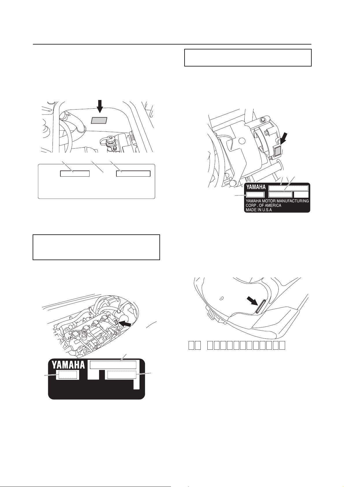
Primary I.D. number
The primary I.D. number is stamped on a
label attached to the inside of the engine
compartment.
1. Model name
2. Hull type
3. Primary I.D. number
Starting primary I.D. number
F3K: 800101
F3L: 800101
Engine serial number
The engine serial number is stamped on a
label attached to the engine unit.
Starting engine serial number
6EV: 1000001
Jet pump unit serial number
The jet pump unit serial number is stamped
on a label attached to the intermediate housing.
1. Jet pump unit name
2. Jet pump unit type
3. Jet pump unit serial number
Hull identification number (H.I.N.)
The H.I.N. is stamped on a plate attached to
the boarding platform.
1. Engine name
2. Engine type
3. Engine serial number
1
Model feature
b
a
c
d
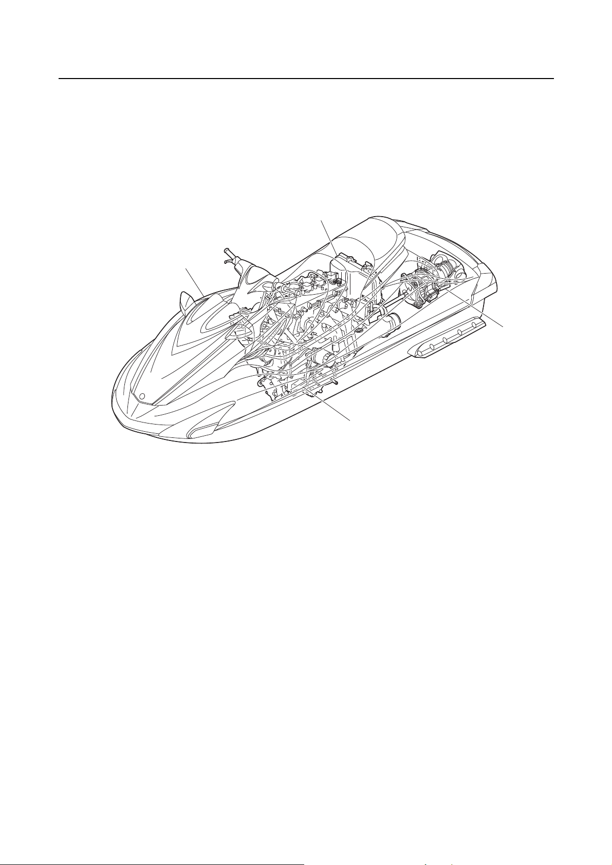
Model feature
General feature
The FZR (F3L) and FZS (F3K) have been developed based on the FZR (F2R) and FZS (F2C) and a
newly designed high output, 1.8L supercharged engine and a larger jet pump are adopted.
The new 6EV engine, developed based on the 6AN engine, is fitted with a high-performance supercharger, large-sized air cooler, and high-efficiency oil cooler to achieve higher engine output.
The ride plate has a new design to improve the straight-running stability.
a. Power unit
• 4-stroke, L4, DOHC, 16 valve, 1812 cm³
engine with electronic fuel injection
• Supercharged
• Single throttle body
• 4-in-1 exhaust system
• Wet-sump lubrication
b. Jet pump
• Stainless steel, 3-blade, ø160 mm, 17.0°
pitched impeller
• Impeller turning direction: counterclockwise (when viewed from the rear)
• Aluminum jet thrust nozzle
• Q.S.T.S.
c. Electrical
• Electronic control throttle valve system
• In-tank fuel pump module
• Dual analog meter
• L-MODE
•OTS
• Self-diagnosis system with YDIS (New version 2.12)
d. Deck and hull
• Rounded keel hull
• NanoXcel hull, NanoXcel deck
• Telescopic steering system
2
Model equipment comparison table
1
1
2
2
A
B
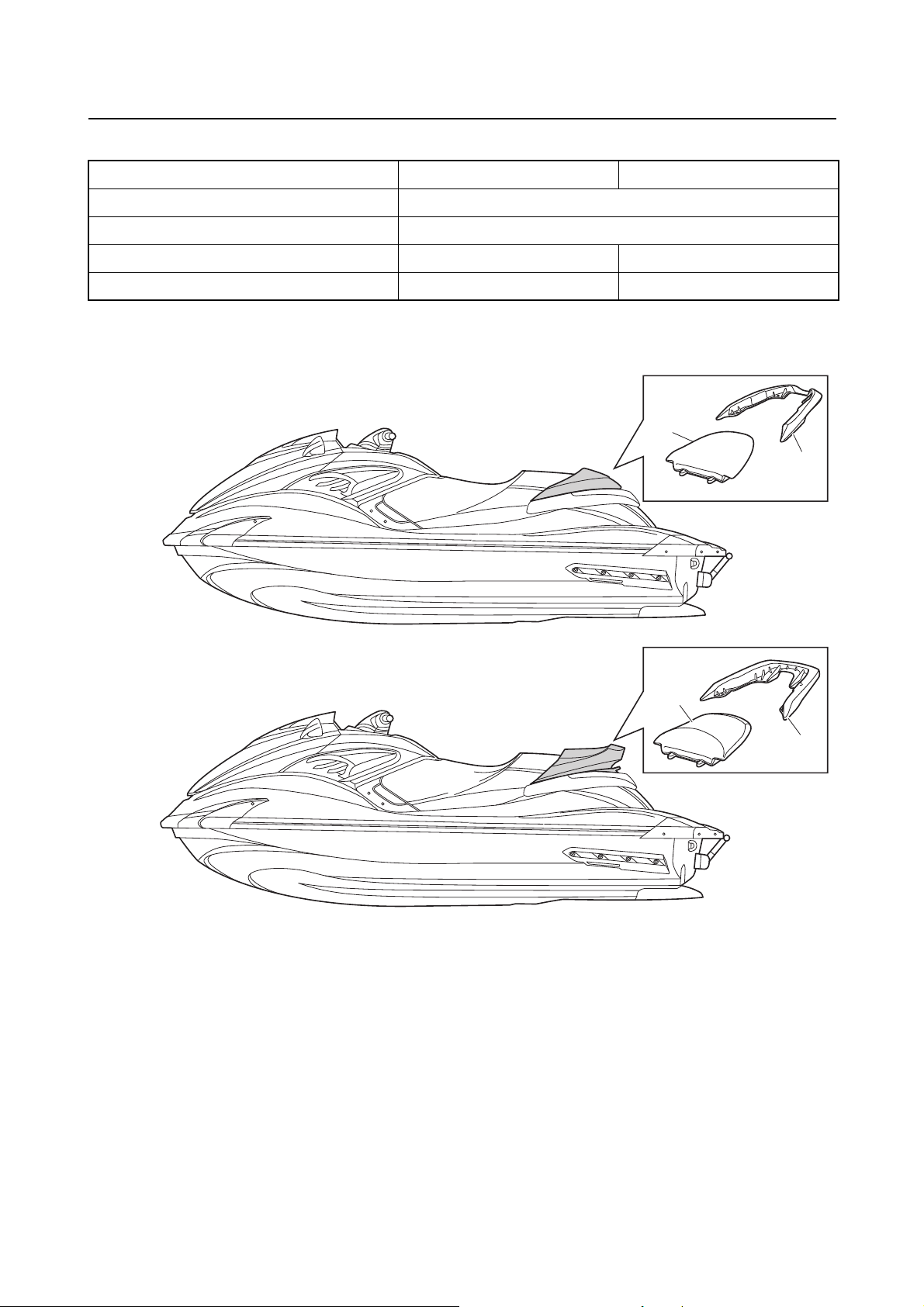
Model FZR FZS
Total length 3.37 m (132.7 in)
Width 1.23 m (48.4 in)
Dry weight 375 kg (827 lb) 377 kg (831 lb)
Seats *1 2- seater 3-seater
*1: The rear seats “1” and handgrips “2” for the FZR and FZS have different shape.
A. FZR
B. FZS
3
Technical tips
1
2
3
5
4
6
7
8
9
10
11
12
13
14
15
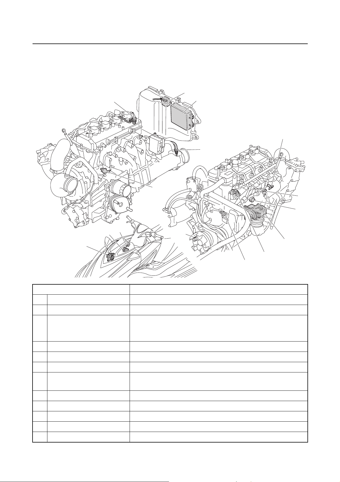
Technical tips
Engine control
The ECM controls ignition timing and fuel injection with information received from the sensors and
switches installed on the engine as well as utilizing the base map saved in the ECM.
Part name Function
1 Cam position sensor Detects the rotational position of the camshaft.
2 Slant detection switch Detects whether the watercraft is capsized.
3 ECM
4 Thermo sensor Detects the temperature of the exhaust cooling water.
5 Oil pressure switch Detects the pressure of the engine oil.
6 Thermo switch Detects engine overheating.
Intake air temperature sen-
7
sor
8 Knock sensor Detects engine knocking.
9 TPS Detects the opening angle of the ETV.
10 Intake air pressure sensor Detects the pressure of the intake air.
11 Engine temperature sensor Detects the temperature of the cylinder block.
12 Pickup coil Detects the crankshaft angle.
Properly controls ignition timing, fuel injection timing and volume, opening angle of the ETV, and fail-safe function with
information received from the sensors and switches.
Detects the temperature of the intake air.
4

Part name Function
13 APS Detects the opening angle of the throttle lever.
14 Steering sensor
15 Reverse sensor Detects the R position of the shift lever.
Detects when the handlebar is turned all the way to the right or
left and a load is applied.
5
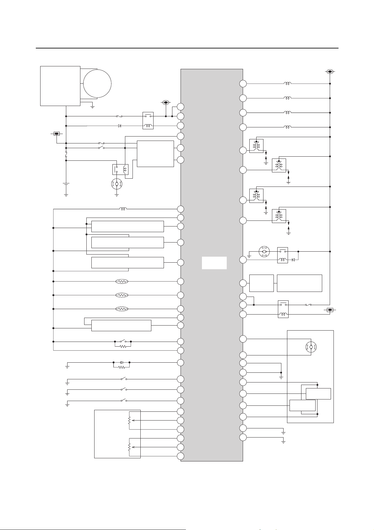
ECM circuit diagram
35
37
50
34
36
49
72
64
79
14
58
59
84
83
85
86
61
60
81
47
39
45
80
78
52
62
70
44
42
43
41
46
67
21
38
20
27
7
8
26
3
16
18
15
23
13
25
17
40
5
1
1. Rectifier
regulator
3. Fuse (20 A)
4. Main relay
9. Remote
control
receiver
5. Fuse (3 A)
7. Fuse
(30 A)
6. Engine start switch
10. Battery
8. Starter relay
11. Starter motor
12. Pickup coil
13. Cam position sensor
14. Intake air pressure sensor
15. Reverse sensor
16. Intake air temperature sensor
17. Engine temperature sensor
18. Thermo sensor
19. Steering sensor
41. ETV relay
39. Dual analog
meter
38. (YDIS)
37. Fuel pump relay
36. Fuel pump module
35. Ignition coil #4
34. Ignition coil #3
33. Ignition coil #2
32. Ignition coil #1
28. Fuel injector #1
29. Fuel injector #2
30. Fuel injector #3
31. Fuel injector #4
20. Slant detection switch
40. Fuse (10 A)
2. Stator
coil
46. ECM
21. Knock sensor
22. Oil pressure switch
23. Thermo switch
24. Engine shut-off switch
25. APS
b. Ground
b. Ground
26. APS 1
a. 5 V
a. 5 V
b. Ground
27. APS 2
a. 5 V
45. TPS 2
44. TPS 1
42. ETV
43. ETV motor
Technical tips
6

1. Rectifier regulator
2. Stator coil
3. Fuse (20 A)
4. Main relay
5. Fuse (3 A)
6. Engine start switch
7. Fuse (30 A)
8. Starter relay
9. Remote control receiver
10. Battery
11. Starter motor
12. Pickup coil
13. Cam position sensor
14. Intake air pressure sensor
15. Reverse sensor
16. Intake air temperature sensor
17. Engine temperature sensor
18. Thermo sensor
19. Steering sensor
20. Slant detection switch
21. Knock sensor
22. Oil pressure switch
23. Thermo switch
24. Engine shut-off switch
25. APS
26. APS 1
27. APS 2
28. Fuel injector #1
29. Fuel injector #2
30. Fuel injector #3
31. Fuel injector #4
32. Ignition coil #1
33. Ignition coil #2
34. Ignition coil #3
35. Ignition coil #4
36. Fuel pump module
37. Fuel pump relay
38. (YDIS)
39. Dual analog meter
40. Fuse (10 A)
41. ETV relay
42. ETV
43. ETV motor
44. TPS 1
45. TPS 2
46. ECM
a. 5 V
b. Ground
, : Indicate a connection between the symbols.
7
 Loading...