

Yamaha GT1, GTMX Service Manual

NOTICE
This manual has been
Dealers and their qualified mechanics.
certain basic mechanical precepts and procedures inherent
and understood
Without such basic knowledge, repairs or service
unsafe, and for this reason we must advise
Authorized Yamaha dealer who
Other information
and
is
necessary
by
written
the
by Yamaha Motor Company for use by Authorized Yamaha
In
light of this purpose
reader.
to
that
all
repairs
is
in
possession of
is
produced by
to
provide total technical coverage regarding
the
U.S. distributor, Yamaha International Corporation,
it
has been assumed
to
our product are already known
this model may
and/or
the
requisite basic product knowledge.
the
_render
the
service be performed by an
product.
machine
**************************************************
The Research, Engineering, and Service Departments of Yamaha are continually striving
further
inevitable and changes
Yamaha Dealers and will, where applicable, appear
improve
all
models manufactured by
in
specifications or procedures will be forwarded
the
company. Modifications are therefore
to
all
Authorized
in
future
editions
of
this manual.
**************************************************
that
to
YAMAHA
©1973 YAMAHA
GTl/GTMX
2ND
6600 ORANGETHORPE AVENUE
BUENA PARK,
SERVICE MANUAL
REVISED
DECEMBER
INTERNATIONAL
LIT-11613-67-73
EDITION
1973
CALIF.
CORPORATION
90620
)
I
FOREWORD
The Yamaha GT1-GTMX
but
it
is
also built to EXCEL. in high speed performance over the road or highways.
This manual
technical information and service instructions essential to the GT1-GTMX.
is
offered so
is
originally designed for
that
all Yamaha dealers and service engineers will become familiar with the
offthe-road
riding
as
a trails machine or a scrambler,
j
GT
1
GTMX

CONTENTS
CHAPTER
1 • 1 P
1-2
1
-3
1-4
1
-5
CHAPTER
2-1
2-2
2-3
CHAPTER
3-1
3-2
CHAPTER
4-1
1.
GENERAL
refile
· · · · · · · · · · · · · · · · · · · · · · · · • • • • • • • • • • • • • • • • • • • • • • • • • • • • • • • • • • • • • • • • • • • • • 1
Features
Specifications
Performance
Tools
2.
What
Features
Handling
3.
Reed
Action
4.
Engine
and
YAMAHA
is
WHAT
Valve-construction
ENGINE · · · · · · · · · · · · · · · · · · · · · · · · · · · · · · · · · · · · · · · · · · · · · · · · · · · · · · · · · · · · · · · ·
· · · · · · · · · · · · · · · · · · · · · · · · · · · · · · · · · · · · · · · · · · · · · · · · · · · · · · · · · · · · · · · 1
of
Yamaha
Curves
Instruments
AUTOLUBE
YAMAHA
of
YAMAHA
the
Oil
IS
of
Piston
Removal
&
THE
GT1 · GTMX
Performance,
· · · · · · · · · · · · · · · · · · · · · · · · · · · · · · · · · · · · · · · · · · · · · · · · · · · · · · · 6
for
Shop
(Automatic,
Autolube?
Autulube
Pump
· · · · · · · · · · · · · · · · · · · · · · · · · · · · · · · · · · · · · · · · · · · · · · · · · · · · · 9
TORQUE
and
in
the
torque
· · · · · · · · · · · · · · · · · · · · · · · · · · · · · · · · · · · · · · · · · · · · · · · · · · · · · · · · · ·
· · · · · · · · · · · · · · · · · · · · · · · · · · · · · · · · · · · · · · · · · · 3
GT1 · GTMX
Service
· · · · · · · · · · • · · · · · · · · · · • · · · · · · · · · · · · · · · · · · · · · · · · · 8
· · · · · · · · · · · · · · · · · · · · · · · · · · · · · · · · · · · · · · · · · · · · · 8
INDUCTION?
Handling·······································
induction
· · · · · · · · · · · · · · · · · · · · · · · · · · · · · · · · · 4
· · · · · · · · · · · · · · · · · · · · · · · · · · · · · · · · · · · · 6
Separate
Lubricating
System) · ··
· · · · · · · · · · · · · · · · · · · · · · · · ·
· · · · · · · · · · · · · · · · · · · · · · · · · · · · · · · · · · ·
·· ··
· ·
8
12
13
14
16
16
4-2
4-3
4-4
4-5
4-6
4.7
4-8
4.9
4-10
4-11
4-12
4-13
4-14
4-15
4-1
4-17
4-18
4-19
Reed
Cylinder
Cylinder
Piston
Piston
Piston
Crankcase
Clutch
Primary
Kick
Shift
Drive
Crankcase
Transmission
6
Crankshaft
Bearings
Carburetor
Air
Valve
Starter
Mechanism
Sprocket
Cleaner
· · · · • · · · · · · · · · · · · · · · · · · · · · · · · · · · · · · • · · · · · · · · · · · · · · · · · · · · · · · · · · ·
Head
· · · · · · · · · · · · · · · · · · · · · · · · · · · · · · · · · · · · · · · · · · · · · · · · · · · · · · · · · · · · · · · · · ·
Pin
Ring
· · · · · · · · · · · · · · · · · · · · · · · · · · · · · · · · · · · · · · · · · · · · · · · · · · · · · · · · · · · · · · · · · · · ·
· · · · · · · · · · · · · · · · · · · · · · · · · · · · · · · · · · · · · · • · · · · · · · · · · · · · · · · · · · · · · · · · · · · ·
Drive
· · · · · · · · · · · · · · · · · · · · · · · · · · · · · · · · · · · · · · · · · · · · ·
· · · · · · · · · · · · · · · · · · · · · · · · · · · • · · · · · · · · · · · · · · · · · · · · · · · · · · · · · · · · · · · ·
• • • • • • · · · · · · · · · · · · · · · · · · · · · · · · · · · · · · · · · · · · · · · · · · · · · · · · · · · · · · · ·
Cover
· · · · · · · · · · · · · · · · · · · · · · · · · · · · · · · • • · · · • · · · · · · · · · · · · · · · · · · · · · · · · · · ·
and
· · · · · · · · · · · · • • • • • · · · · · · · · · · · · · • • • • • • • • · · · · · · · · · • • • • • • · · · · · · · · · ·
(R.
H.)
• · · · · · · · · · · · · · · · · · · · · · · · · · · · · · · · · · · · · · · · · · · · · · · · · ·
Gear
· · · · · · · · · · · · · · · · · · · · · · · • · · · · · · · · · · · · · · · · · · · · · · · · · · · · · · ·
Mechanism
· · · · · · · · · · · · · · • · · · · · · • · · · · · · · · · · · · · · · · · · · · · · · · · · · · · · · · · · · · 33
· · · · · · · · · · · · · · · · · · · · · · · · · · • • • • • • · · · · · · · · · · · · · · · · · · · · · · · · · · ·
Assembly
· · · · · · · · · · · · · · · · · · · · · · · · · · · · · · · · · · · · · · · · · · · · · · · · · · · · · · · · · · · · · ·
Oil
Seals
· · · · · · · · · · · · · · · · · · · · · · · · · · · · · · · · · · · · · · · · · · · · · · · · · · · · · · · · · · · · · ·
· · ··· · · · · · · · · · · · · · · · · · · · · · · · · · · · · · · · · · · · · · · · · · · · · · · 31
· · · · · · · · · · · · · · · · · · · · · · · · · · · · · · · · · · · · · · · · · · · · · · · · · · ·
• • • • • · · · · · · · · · · · · · • • • • • • • • · · · · · · · · · • • • • · · · · · · · · · · · ·
·'
· · · · · · · · · · · · ·
19
20
20
22
22
23
25
26
30
34
35
37
40
42
43
45
CHAPTER
5-1
5-2
5-3
5-4
5-5
5-6
5-7
5-8
5-9
5-10
5-11
5-12
5-12
5.
CHASSIS
Front
Rear
Rear
Tires
Front
Wheel
Wheel
Sprocket
and
Forks
Shocks
Gas
Tank
Rear
Swing Arm • • • • • • • • • • • • • • • • • • • • • • • • • • • • • • • • • • • • • • • • • • • • • - • • • • • • • • • • •..
Steering
Oil
Tank,
Frame
Handlebars
Miscellaneous
46
46
• • • • • • • • • • • • • • • • • • • • • • • • • • • • • • • • , , •
Wheel
Tubes
· · · · · · · · · · · · · · · · · · · · · · • • • • • • • • • • • • • • • • • • • · • · · · · · · · • ·
· · · · · · · · · · · · · · · · · · · · · · · · · · · • • • • • • • • • • • • • • • • • • • • • • · · · · · · · ·
• • • • • • • • • • • • • • • • • • • • • • • • • • • • • • • • • • • • • • • • • • • • • • • • • • • • • • • • • • • • • •
· • • • • • • • • • • • • • • • • • • • • • • • • • • • • • • • • • • • • • • • • •
• • • • • • • • • • • • • • • • • • • • • • • • • • • • • • • • • • • • • • • • • • • • • • • • • • • • • • • • • • • • • • • •
...
, • . • • • • • • • • • • • • • • • • • • • • •
•.
• • • • • • • • • • • • • • • • • • • • • •
50
53
54
54
57
58
58
Head
· · · · · · · · · · · • • · · · · · · · · · · · · · · · · · · · · · · · · • • • • • • • • • • • • • • • • • • • • • • • • • • · · · · 61
· · · · • · · · • · · · · · · · · · · · · · · · · · · · · · • • • • • • • • • • • • • • • • • • • • • • • • • • • · • ·
Battery
Box
and
Tool
Box
· · · · · · · • • • • • • • • • • • • • • • • • • • • • • • • • · • · · ·
60
61
· · · · · · · · · · · · · · · · · · · · · · · · · · · · · · · · · • • • • • • • • • • • • • • • • • • • • • • · · · · · · · · 61
· · · · · · · · · · · · · · · · · · · · · · · · · · · · · · • • • • • • • • • • • • • • • • • • • • • • • • • • · · · · 61
CHAPTER
6-1
6-2
6-3
6-4
6-5
6-6
6-7
6-8
6-9
6-10
6-11
6-12
6.
ELECTRICAL
Description
Table
Connection
Ignition
Ignition
Ignition
Condenser
Charging
Battery
Checking
Spark
Lighting
SYSTEM
· · · · · · · · · · • • • · • • • • • • • • • • • • • • • • • • • • • • • • • • • • • • • • • • • • • • • • • • • • • • • •
of
Component
Diagram
System-Function
Timing
Coil
System
• • • • • • • • • • • • • • • • • • • • • • • • • • • • • • • • • • • • • • • • • • • • • • • • • • • • • • • • • • •
· · · · · · · · · · · · · · · · · · · · · · · · · · · · · · · · • • • • • • • • • • • • • • • • • • • • • • • • • • • • • •
• • • • • • • • • • • • • • • • • • • • • • • • • • • • • • • • • • • • • • . • • • . , • • • • • • • • • • • • • • • • • • • •
· · · · · · · · · · · · · · · · · · · · · · · · · · · · • • • • • • • • • • • • • • • • • • • • • • • • • • • • • •
• • • • • • • • • • • • • • • • • • • • • • • • • • • • • • • • • • • • • • • • • • • •
the
Main
Switch
Plug
· · · · · • · · · · • · · · · · · · · · · · · · · · · · · · · · · · · · · · · · • • · · · · · · · · · · · · · · · · · · · ·
and
Signal
· · · · · · · · · · · · · · · · · · · · · · · · · · · · · · · · · · · · · • · • · · · · · · · · · ·
Parts
• • • • • • • • • • • • • • • • • • • • • • • • • • • • • • • • • • • • • • • • • • • • • • • • • • • • • • •
Systems
· · · · · · · · · · · · · · · · · · • • • • • • • • • • • • • • • • · • · · · · · · · · · · · ·
and
Service
(removed
· · · · · · · · · · · · · · · · · · · · · · · · · · · · · · · · · · · · · ·
•.
• • • • • • • • • • • • • • • • • • • •
from
the
chassis)
· · · · · · · · · · · · · · · · · · · ·
• • • · · · · · · · · · · · · · · · · · · · · · · · · · · · · · · · · · · · · · · · · ·
62
62
62
62
63
63
63
63
64
65
66
66
67
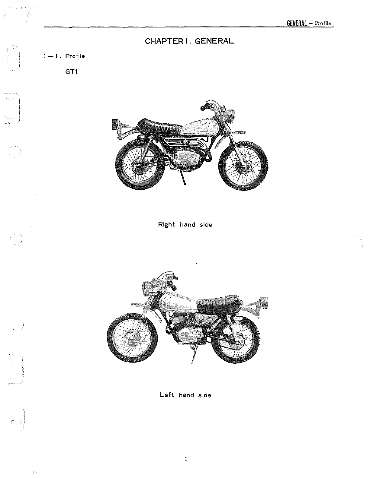
GENERAL
- Profile
l I - I .
Profile
GTI
CHAPTER
I.
GENERAL
Right
Left
hand
hand
side
side
-1-
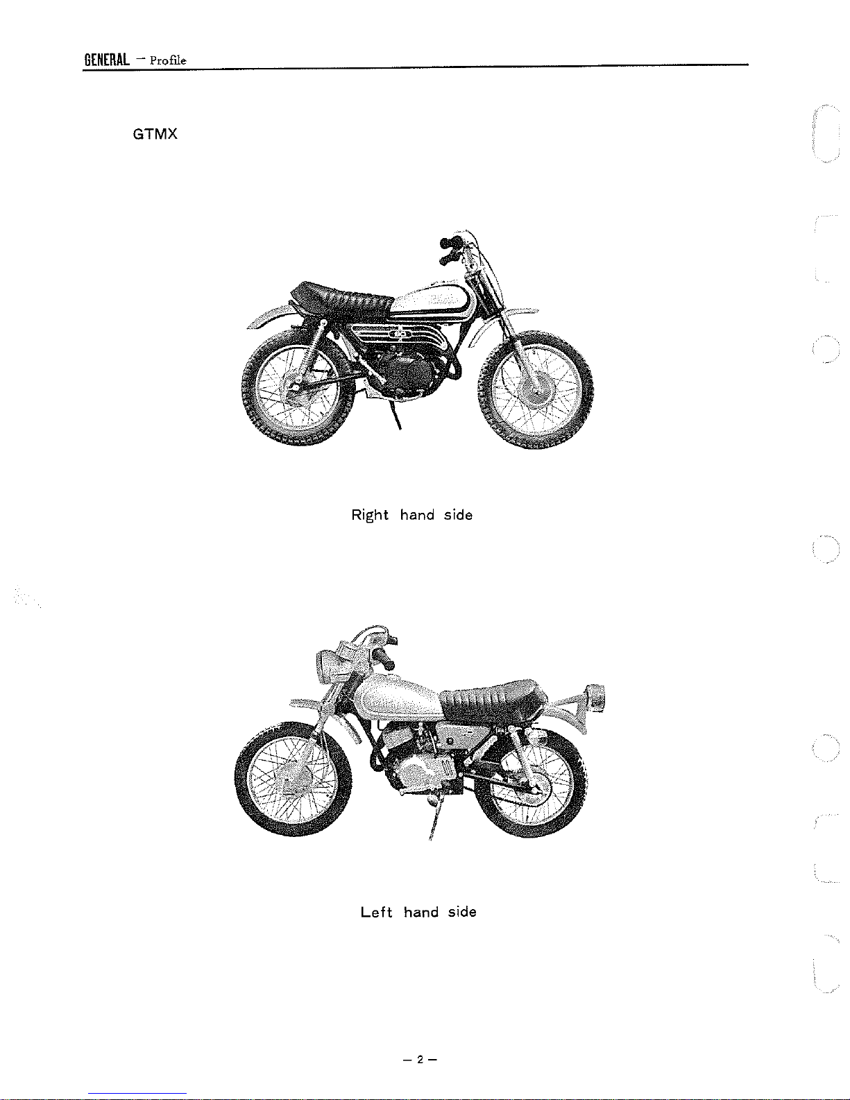
GENERAL
- Profile
GTMX
Right hand side
Left
hand side
-2-
j
1
-2.
1.
2.
3.
4.
5.
6.
Features
Torque
The newly designed 5-port cylinder
adoption
entire range
Highly-dependable
Yamaha
Easy
The engine
back
To
Powerful
Patented waterproof, dustproof brake drums provide safe, fade-free braking on wet
Induction
Auto
Starting
to
neutral. This
start the engine, kick the kick pedal.
Front Fork
The Yamaha GT1-GTMX employs a
characteristics. Its
of
Yamaha
of
an
improved
of
speed
from
Yamaha
lube provides superior engine lubrication that extends the life
can
be started by simply disengaging the clutch
is
Brakes
GTI
·GTMX
has
greatly improved scavenging efficiency
reed
valve
for
intake ensures steady and smooth engine performance throughout the
low
to
high.
Autolube
a valuable convenience
and
to
the rider. The GT1-GTMX
Design
front
fork
design well-known
use
assures
the rider
of
the ultimate suspension
kicking the kick pedal
for
Tires
The Yamaha
particular tread
road
usage.
GT1-GTMX
is
one
of
is
fitted
with
tires having a universal
the most versatile available.
It
type
gives
maximum trail traction
GENERAL
even
tread pattern
- Features
at
of
the engine.
for
its strength and superior handling
the roughest terrain.
of
Yamaha
all
speeds.
without
is
equipped
or
dusty
roads.
as
standard equipment. This
and
yet
is
GTI
In addition, the
shifting
with
a magneto.
compatible
•GTMX
gears
with
7.
Carburetor
Yamaha's starter feature
Yamaha GT1-GTMX
Starter
Feature
is
already we!l·known for its
is
quick
starting under all conditions.
easy
starting. Equipped
with
this unique carburetor, the
l
-3-
GENERAL-
Specifications & Performance GTJ-GTMX
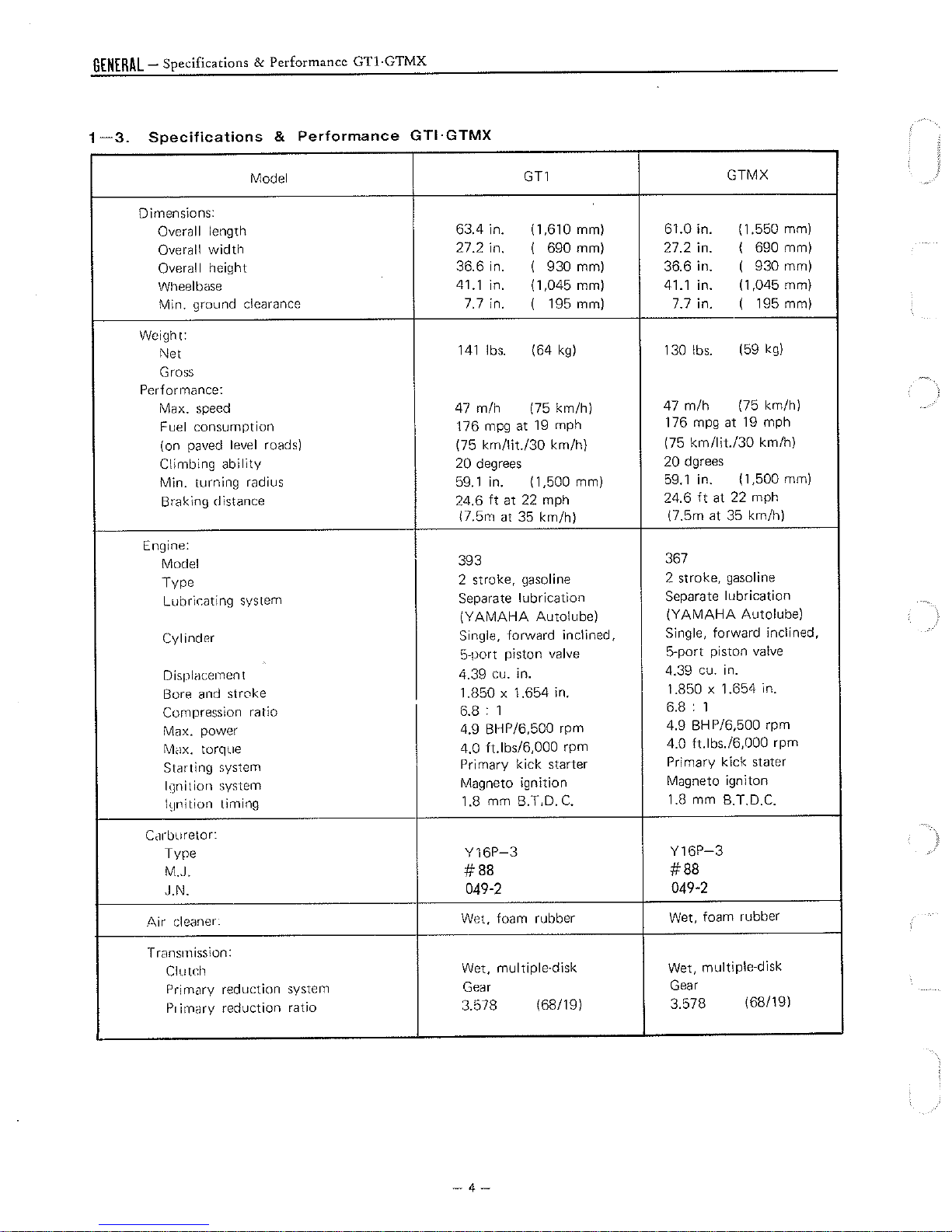
1-3.
Specifications
&
Model
Performance
GTl·GTMX
Dimensions:
Overall length
Overall
Overal I height
Wt1eelbase
Min. ground
Weight:
width
clearance
Net
Gross
Performance:
Max. speed
Fuel
consumption
( on paved I
Climbing
eve
I roads) (75
ability
Min. turning radius 59.1 in.
Braking distance
Engine:
Model
Type
Lubricating
Cylinder
Displacement
Bore and stroke
Compression
Max. power
Mdx.
Starting
I\Jnition system
l~Jnition
system
ratio
torque
system
timing
GTl
63.4 in. (1.610 mm)
27.2 in.
36.6 in.
41.1
in. (1,045 mm)
7.
7 in.
141
lbs.
47
m/h
176 mpg at
km/lit./30
20
degrees
24.6
ft
(7.5rn
at
393
2
stroke,
Separate
(YAMAHA
Single,
5-port
4.39 cu. in.
1.850 X 1.654 in.
6.8 : 1
4.9 BHP/6,500 rpm
4.0 ft.lbs/6,000 rpm
Primary
Magneto
1.8 mm B.T,D.
690 mm) 27.2 in.
I
930 mm) 36.6 in.
I
195 mm) 7.7 in.
I
(64
kg)
(75 km/h)
19
mph
km/h)
(1,500 mm)
at 22 mph
35 km/h)
gasoline
lubrication
Autolube)
forward
piston
valve
kick
starter
ignition
inclined,
C.
GTMX
61.0 in. (1.550 mm)
690 mm)
I
930
mm)
I
41.1
130 lbs.
47
m/h
176 mpg at
(75
km/lit./30
20 dgrees
59.1
24.6
(7.5m at 35 km/h)
367
2 stroke, gasoline
Separate lubrication
(YA
MAHA
Single, forward inclined,
5-port
4.39 cu. in.
1.850 X 1.654 in.
6.8 : 1
4.9 BHP/6,500 rpm
4.0 ft.lbs./6,000 rpm
Primary
Magneto
1.8 mm B.T.D.C.
(1,045 mm)
in.
I
(59
(75 km/h)
19
(1,500 mm)
in.
ft
at 22 mph
Autolube)
piston valve
kick
igniton
195 mm)
kg)
mph
km/h)
stater
C&buretor:
Type
M . .I.
.I.N.
.Air cleaner:
Trans1nission:
Clutch
Prirnc1ry reduction
Primary
reduction
system
ratio
Y16P-3
#88
049-2
Wet, foam
Wet,
multiple-disk
Gear
3.578
-4-
rubber
(68/19)
Y16P-3
#88
049-2
Wet, foam rubber
Wet, multiple-disk
Gear
3.578
(68/19)
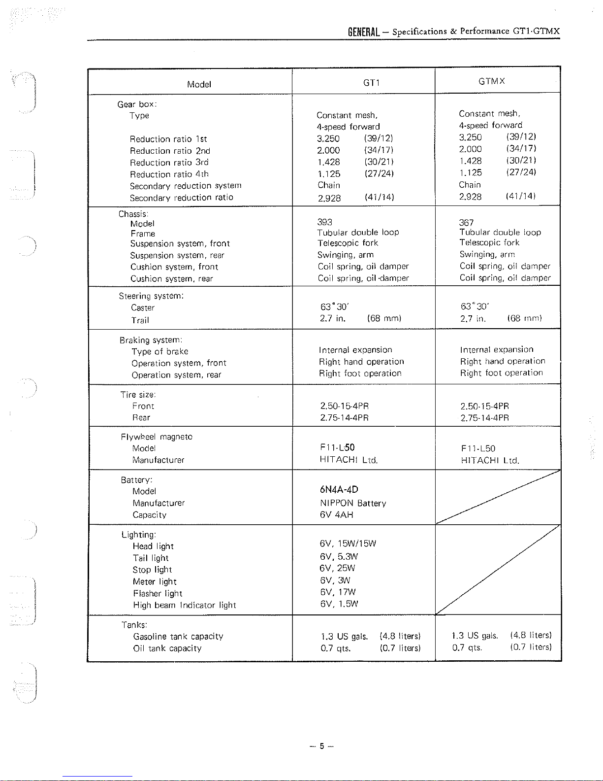
GENERAL-
Specifications & Performance
GTl·GTMX
Model
Gear
box:
Type
Reduction ratio 1st
Reduction ratio 2nd
Reduction ratio 3rd
Reduction ratio
4th
Secondary reduction system
Secondary reduction ratio
Chassis:
Model
Frame
Suspension system,
Suspension system, rear
Cushion system,
front
front
Cushion system, rear
Steering system:
Caster
Trail
Braking system:
Type
of
brake
Operation system,
Operation system, rear
front
GT1
Constant mesh,
4-speed forward
3,250
2,000
1.428
1.125
Chain
2.928
393
Tubular double loop Tubular double
Telescopic fork
Swinging, arm
Coil spring, oil damper
Coil spring, oil •damper
63'
2.7 in.
I nterna! expansion
Right hand operation
Right
(39/12)
(34/17)
(30/21 I
(27/24)
(41/14) 2.928
30'
(68 mm)
foot
operation
GTMX
Constant mesh,
4-speed forward
3.250
2.000
1.428
1.125
Chain
367
(39/121
(34/17)
130/21 I
(27 /24)
(41/14)
Telescopic fork
Swinging, arm
Coil spring, oil damper
Coil spring, oil damper
63'
30'
foot
168
operation
2.7 in.
I nterna! expansion
Right hand operation
Right
loop
rnm)
Tire size:
Front
Rear
Flywbeel magneto
Model
Manufacturer
Battery:
Model
Manufacturer NIPPON Battery
Capacity
)
Lighting:
Head
light
Tail light
Stop light
Meter light
Flasher light
High beam Indicator light
Tanks:
Gasoline tank capacity 1.3
Oil tank capacity 0.7 qts.
2.50-15-4PR
2.75-14-4PR
F11-L50
HITACHI
6N4A-4D
6V
4AH
6V,
15W/15W
6V,
5.3W
6V,
25W
6V,
3W
6V, 17W
6V,
1.5W
US
gals.
Ltd.
(4.8 liters)
(0. 7 liters)
2.50-15-4PR
2.75-14-4PR
F11-L50
HITACHI
Ltd.
~
1.3
US
0.7 qts.
gals.
(4.8 liters)
(0.7 liters)
-5-
GENERAL
1
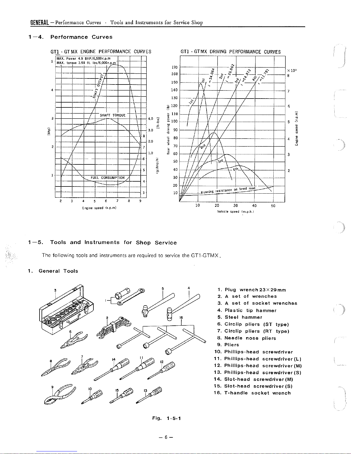
-4.
-Performance
Performance
GTl •
MAX.
MAX. torque 3.98
4
GT
MX
ENGINE
Power 4.9
,~
/
I
I
I
"-
I
I
'
'
2 4
Curves ·
Curves
BHP/6,500r.p.m
ft.
lbs/6,000r.~-
SI
~c
fl
0;
I
I
I
~
I
--
FUEL
'
5
Engine speed
Tools
and
PERFORMANCE
~
"
/
SHAFT
\
I
TORQUE
'--
'
"
CONSUMPTION
8 9
(r.p.m)
Instruments
CURVES
I
I
I
4.0
3.0
8
2.0
"
7
1.0
.,
I
I
5
I
4
3
for Service Shop
GTl •
170
160
150
140
130
~
£!
120
i
110
g_
100
~
00
'
~
90
80
70
60
50
40
30
1//1
20
I
1//
10
ii'
GTMX
-
~
~TI/_
~
·-
....
3/
I I I I
( (
I
I
I
I I
(
I
I
~
II
/'
I
/ / -t;.\ "
/1
I I
Ill
/ \
,,
. . tance
Runnins
10
DRIVING
~
0
~-
~
PERFORMANCE
of
l:,-""
-1---
f,"
..
-"'
I I
I
I I
,f
I
'\
I
\
__\....
,1,\'I\ \ ........
'
1es1s
20
on
30
Vehicle speed {m.p.h.)
~
i?
...
I
\
"'
\evel road
,._">
°>-
..
"
,,.
-·
I
'
\
40
-
,,·
.f
...
'
"
CURVES
o,...,
'\
'
50
X
}Ol
8
7
s
e
e
5
"
~
0
.
4
~
~
3
2
1
1.
-5.
Tools
The
following
General
and
Tools
Instruments
tools
and
for
Shop
instruments are required
Service
to
service
the
GT1-GTMX.
1.
Plug
2. A set
3. A set
4.
Plastic
5.
Steel
6.
Circlip
7.
Circlip
8.
Needle
9.
Pliers
10.
Phillips-head
11.
Phillips-head
12.
Phillips-head
13.
Phillips-head
14.
Slot-head
15.
Slot-head
16.
T-handle
wrench
of
wrenches
of
socket
tip
hammer
pliers
pliers
nose
screwdriver
screwdriver
socket
23 x 29
wrenches
hammer
{ST
{RT
pliers
screwdriver
screwdriver
screwdriver
screwdriver
wrench
mm
type)
type)
(L)
(M)
(S)
(M)
{S)
Fig.
1-5-1
-6-
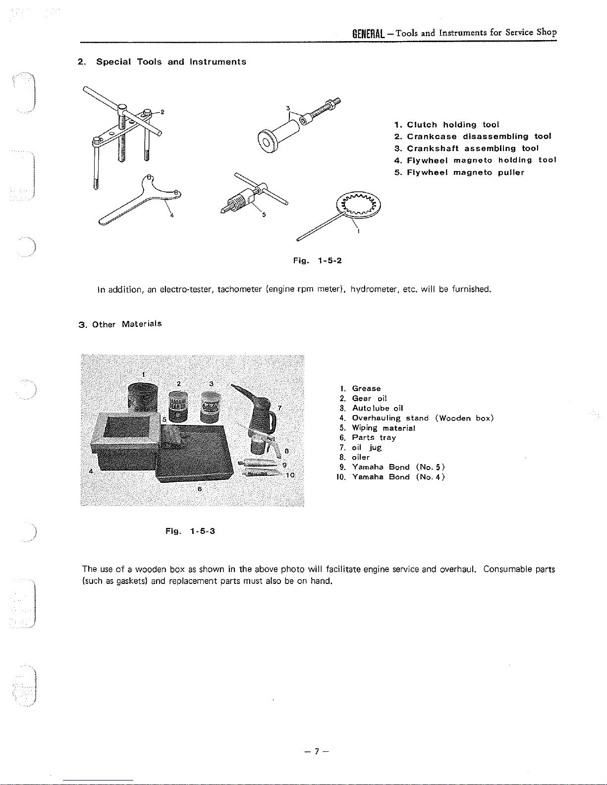
2.
Special
Tools
and
Instruments
Fig.
1-5-2
GENERAL
-Tools
1.
2.
3.
4.
5.
and
Instruments
Clutch
Crankcase
Crankshaft
Flywheel
Flywheel
holding
disassembling
assembling
magneto
magneto
for
tool
Service
holding
puller
Shop
tool
tool
tool
In addition,
3.
Other
)
The
use
of
(such
as
gaskets) and replacement parts must also be on hand.
an
electro·tester, tachometer (engine rpm meter). hydrometer, etc.
Materials
_1
5
Fig.
a wooden box
2 3
I
as
I
6
1-5-3
shown in the above photo
will
be
furnished.
Grease
1.
Gear
2.
3.
4.
5.
6.
8
9
10
will
7.
8.
9.
10.
facilitate engine service
oil
Auto
lube
Overhauling
Wiping
Parts
oil
oiler
Yamaha
Yamaha
material
tray
jug
Bond
Bond
oil
stand
(No.
(No.
(Wooden
5)
4)
and
overhaul. Consumable parts
box)
J
-7-
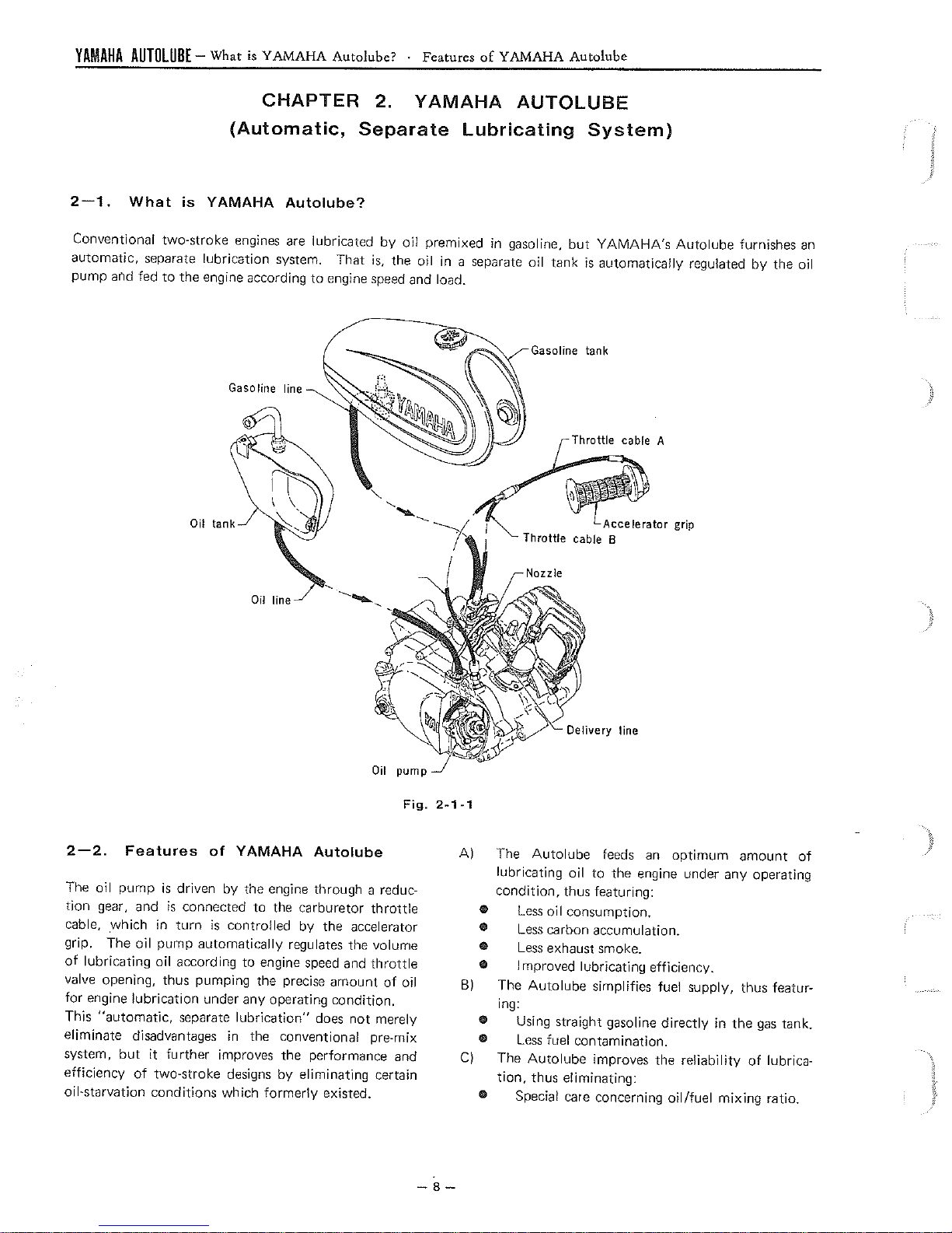
YAMAHA
AUTOLUB[
- What
is
YAMAHA
Autolube? • Features
of
YAMAHA
Autolube
CHAPTER
(Automatic,
2-1.
Conventional two-stroke engines are lubricated
automatic, separate lubrication system.
pump
ar'ld
What
fed
is
YAMAHA
to
the
engine according
Autolube?
to
Gasoline line
Separate
That
engine
2.
YAMAHA
AUTOLUBE
Lubricating
by
oil
premixed in gasoline,
is,
the oil in a separate oil tank
speed
and load.
Throttle
System)
but
YAMAHA's
is
automatically regulated
Gasoline tank
Throttle
cable
cable
Accelerator
B
Autolube
A
grip
furnishes
by
the oil
an
Oil line
Oil
pump
Fig.
2-2.
The
tion gear, and
cable,
grip. The
of
valve opening, thus pumping the precise
for
This
eliminate disadvantages in the conventional pre-mix
system,
efficiency
oil-starvation conditions which
Features
oil
pump
is
_which
lubricating oil according
engine lubrication under any operating
"automatic,
in
oil
pump
but
it
of
two-stroke designs
of
YAMAHA
driven by the engine through a reduc-
is
connected to the carburetor throttle
turn
is
controlled by the accelerator
automatically
separate
further
to
lubrication"
improves the performance and
regulates the volume
engine
speed
by
eliminating certain
formerly
Autolube
and
amount
condition.
does
not
existed.
throttle
of
oil
merely
2-1-1
A) The
Bl
C)
line
Autolube
lubricating oil
condition,
..
Less
..
..
..
The Autolube simplifies fuel supply, thus featur-
ing:
..
..
The
tion,
..
oil consumption .
Less
carbon accumulation.
Less
exhaust smoke .
l mp roved lubricating efficiency .
Using straight gasoline
Less
fuel contamination .
Autolube
thus eliminating:
Special care concerning
feeds
to
the engine under any operating
thus featuring:
improves the
an
directly
oil/fuel
optimum
in
reliability
amount
the
of
mixing
gas
of
tank .
lubrica-
ratio
.
-8-
YAMAHA
AUTOLUB[
- Handling
the
Oil Pump · Checking Minimum Pump Stroke
2-3.
The oil
no
oil pump from the engine, protect
etc., and after reinstalling
correctly. Proper handling
from
The oil
tion
is
consumption
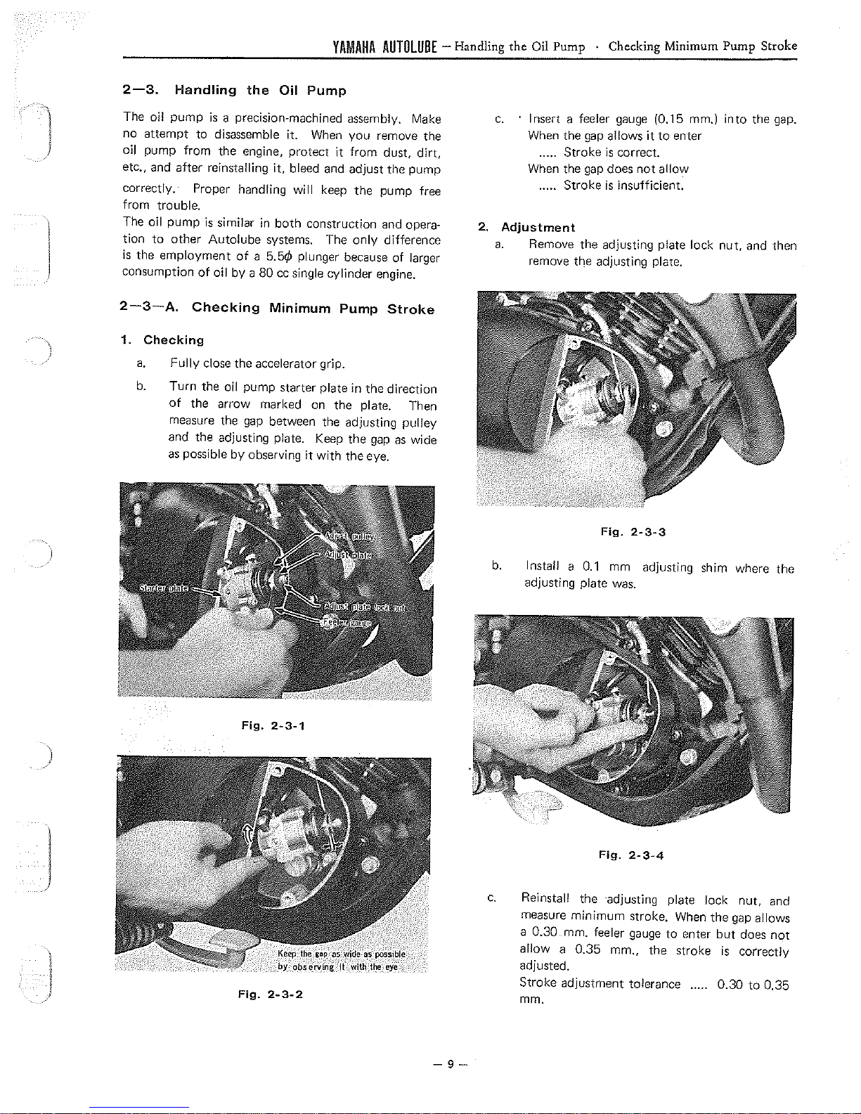
2-3-A.
\
)
1. Checking
Handling
pump
attempt
to
the employment
a.
b.
to
trouble.
pump
is
other
of
Checking
Fully
close the accelerator grip.
Turn the
of
the arrow marked on
measure the
and the adjusting plate. Keep the
the
Oil
is
a precision-machined assembly. Make
disassemble it. When
it,
bleed
will
similar in
Autolube
oil by a 80
oil
both
systems. The
of
a 5.5¢ plunger because
cc
single cylinder engine.
Minimum
pump starter plate
gap
between the adjusting pulley
as possible by observing
Pump
you
remove
it
from
and
adjust the pump
keep
the
pump free
construction and opera-
only
Pump
in
the
the
plate. Then
gap
it
with
the
eye.
the
dust,
dirt,
difference
of
larger
Stroke
direction
as
wide
c.
2.
Adjustment
a.
Insert a feeler
When
the
..... Stroke
When
the
..... Stroke
Remove the adjusting plate lock
remove the adjusting plate.
gap
gap
allows
is
does
is
gauge
(0.15 mm.)
it
to
enter
correct.
not
allow
insufficient.
into
nut,
the
gap.
and then
)
j
l
Fig.
Fig.
2-3-1
2-3-2
Fig.
2-3-3
b.
Install a
adjusting plate
c.
Reinstall the ·adjusting plate lock
measure
a 0.30 mm. feeler
allow
adjusted.
Stroke adjustment tolerance
mm.
0.1
mm adjusting shim where the
was.
Fig.
2-3-4
minimum
a 0.35 mm., the stroke
stroke. When the
gauge
to
enter
gap
but
is
0.30
nut,
and
allows
does
not
correctly
to
0.35
-9-
YAMAHA
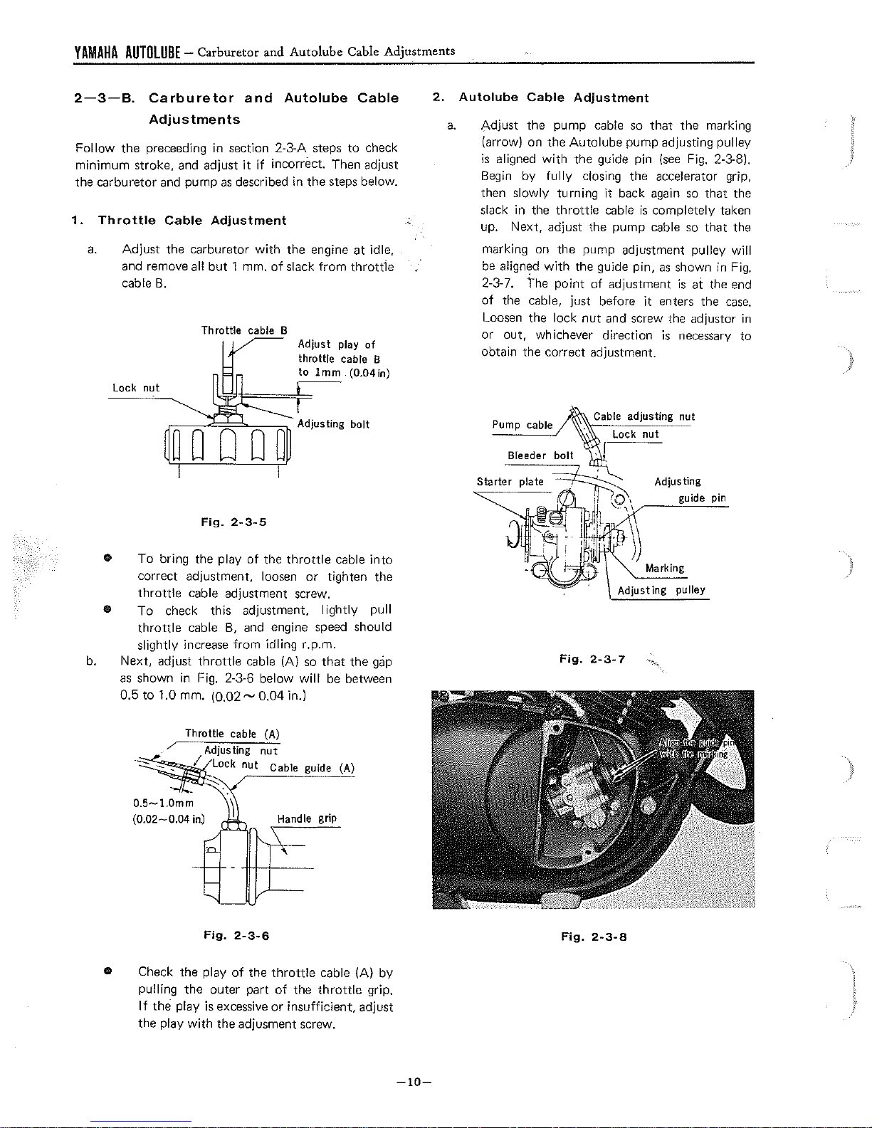
2-3-B.
AUTOLUBE
-
Carburetor
Carburetor
Adjustments
Follow
minimum stroke, and adjust
the
1.
the
carburetor
Throttle
a.
Adjust
and remove all
cable
Lock
preceeding
in
and pump as described
Cable
the carburetor
B.
nut
Adjustment
but
and
Autolube
and
Autolube
section 2-3-A
it
if
incorr8ct. Then adjust
in
with
the
1 mm.
of
slack
Adjust play
throttle cable B
to
Cable Adjustments
Cable
steps
to
check
the
steps below.
engine at idle,
from
throttie
of
1mm (0.04in)
2.
a.
Autolube
Adjust
(arrow} on the
is
Begin
then slowly turning
slack
up.
marking on
Cable
the pump cable
aligned
with
by
fully
in
the
Next,
adjust the pump cable
Adjustment
so
that
Autolube
the
dosing the accelerator grip,
throttle
the
pump adjustment pulley
pump adjusting pulley
guide pin
it
back
again
cable
is
completely taken
be align~d with the guide pin, as shown
2-3-7.
of
Loosen the lock
or
the
point
of
adjustment
the cable, just before it enters
nut
and screw the adjuster
out,
whichever direction
obtain the correct adjustment.
the
(see
is
is
necessary
marking
Fig. 2-3-8).
so
that the
so
that
the
will
in
Fig.
at the end
the
case.
in
to
b.
Fig.
2-3-5
•
To
bring the play
correct adjustment, loosen
throttle
•
To
throttle
slightly increase from idling r.p.m.
Next,
as
shown in Fig. 2-3-6 below
0.5
to
cable adjustment screw.
check this adjustment,
cable
adjust
throttle
1.0 mm. (0.02 ~ 0.04 in.}
/
of
B,
and engine speed should
cable
the
throttle
IA}
will
Handle grip
cable
or
tighten the
lightly
so
that
be
the
between
(A)
into
pull
gap
Pump cable
Fig.
Lock
Adjusting pulley
2-3-7
nut
Adjusting
guide pin
Fig.
2-3-6
• Check the play
pulling
If
the play
th8
the
play
with
of
the
throttle
outer part
is
excessive
the adjusment screw.
of
the
or
insufficient, adjust
cable
throttle
(A}
by
grip.
-10-
Fig.
2-3-8
YAMAHA
AUTOLUBE
- Bleeding
1
J
)
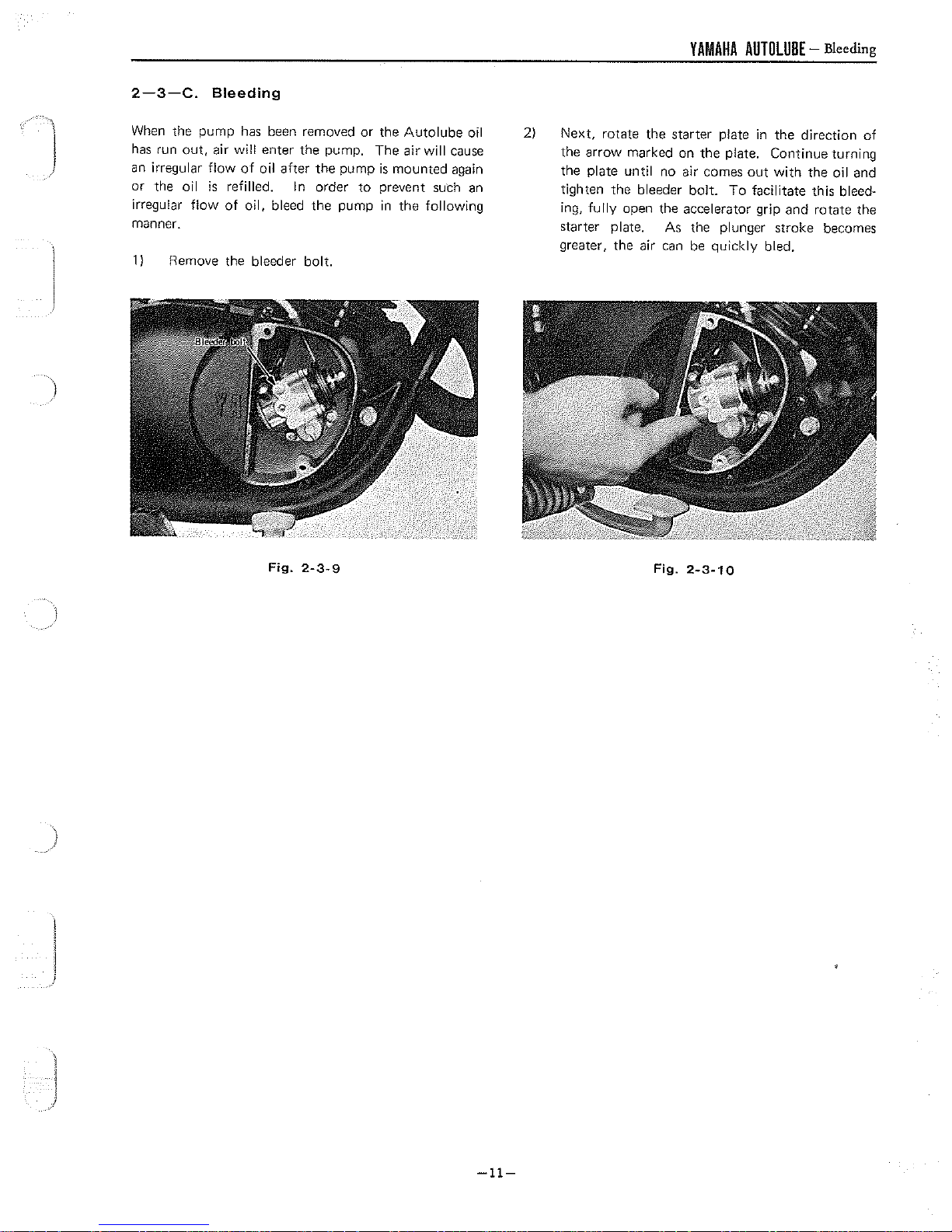
2-3-C.
When
has
run
an
irregular
or
the oil
irregular
manner.
11
Bleeding
the pump
out,
flow
Remove the bleeder bolt.
has
air
will
flow
of
is
refilled. In order
of
oil, bleed the pump
been
removed
enter the pump. The air
oil after
the
or
pump
to
the
Autolube
is
mounted again
prevent
in
the
oil
will
cause
such
an
following
2)
Next,
rotate
the
the arrow marked on
the plate until no air comes
tighten the bleeder
ing,
fully
open the accelerator grip and rotate the
starter plate. As
greater,
the
air can be quickly bled.
starter
the
bolt.
the
plate
in
the
direction
plate. Continue turning
out
with
the oil and
To
facilitate this bleed-
plunger
stroke
becomes
of
Fig.
2-3-9
Fig.
2-3-10
-11-
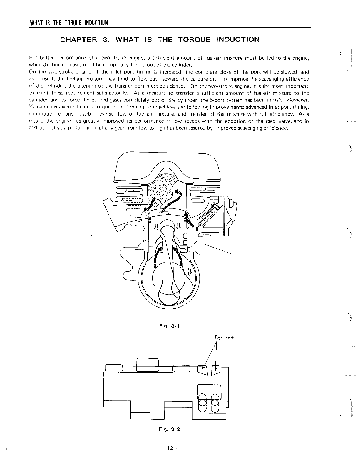
WHAT
IS
THE
TORQUE
INDUCTION
CHAPTER
For
better
performance
while
the
burned gases must be completely forced
On the two-stroke engine, if the
as
a result, the fuel-air
of
the cylinder, the opening
to
meet these requirement satisfactorily. As a measure
cy!inder and to force the burned
Yamaha
elimination
result, the engine
addition,
has
invented a new
ot
any possible reverse
steady performance at any gear
mixture
has
greatly improved its performance at
3.
WHAT
of
a two-stroke engine, a
inlet
port
may tend to
of
the transfer
gases
completely
torque
induction
flow
of
from
IS
timing
flow
port
engine to achieve the
fuel-air
low
THE
sufficient
out
of
is
increased, the complete close
back toward the carburetor.
must
be
out
mixture,
to
high
TORQUE
amount
the cylinder.
sidened. On the two-stroke engine,
to
transfer a
of
the
cylinder,
and transfer
low
has
been assured
of
following
speeds
fuel-air
sufficient
the
with
INDUCTION
mixture
To
amount
5-port
system
improvements; advanced
of
the
mixture
the
adoption
by
improved scavenging efficiency.
must
be
fed
of
the
port
will
improve the scavenging
it
is
the most
of
fuel-air
has
been in
inlet
with
full
of
the
reed
to
the engine,
be
slowed, and
efficiency
important
mixture
use.
efficiency. As a
to
the
However,
port
timing,
valve, and in
I 1
I
I I I 7
Fig.
Fig.
-12-
3-1
3-2
5th
port
I
7
'I
I
I
-.
00
WHAT
IS
THE
TORQUE
INDUCTION
-
Reed
Valve-construction
and
Handling
3-1.
Construction
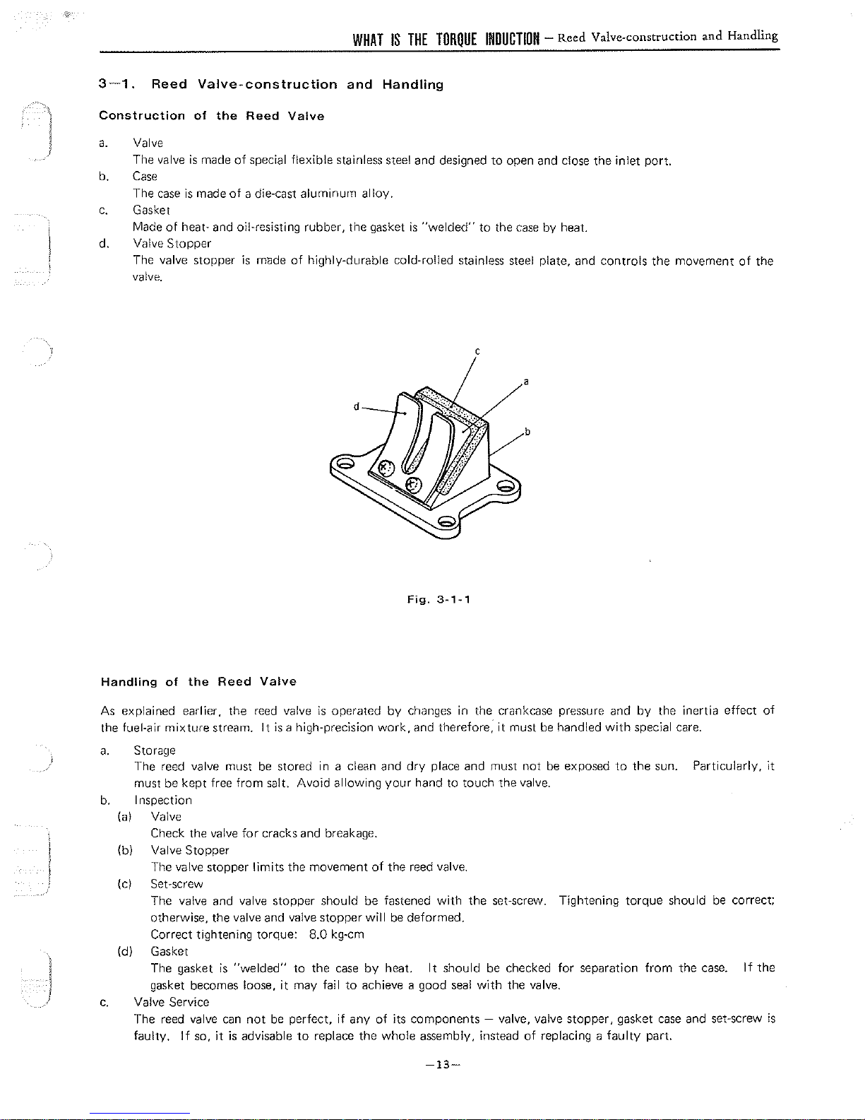
a.
b. Case
c.
d. Valve
Reed
Valve
The
valve
The
case
Gasket
Made
of
Stopper
The valve stopper
valve.
Valve-construction
of
the
Reed
Valve
is
made
of
special flexible stainless steel
is made
heat- and oil-resisting rubber, the gasket
of
a die-cast
is
made
aluminum
of
and
Handling
alloy.
highly-durable cold-rolled stainless steel plate, and controls the movement
and
designed
is
"welded"
C
to
to
the
open
case
and
close
the
inlet
port.
by
heat.
of
the
b
j
Handling
As
explained earlier, the
the fuel-air
a.
b.
(al Valve
(bl Valve
(cl Set-screw
Id)
c.
of
the
Reed
Valve
reed
valve
mixture
Storage
The reed valve must
must be kept free from salt. Avoid allowing
Inspection
Check the valve
The valve stopper
The valve and valve stopper should be fastened
otherwise, the valve and valve stopper
Correct tightening torque: 8.0 kg-cm
Gasket
The gasket
gasket becomes loose,
Valve Service
The reed valve
faulty.
Stopper
If
so,
stream.
for
is
"welded"
can
it
is
advisable
It
is
a high-precision
be
stored in a clean and
cracks and breakage.
limits
the movement
to
it
may fail
not
be
perfect,
to
is
operated
the
case
if
replace the whole assembly, instead
by
work,
your
of
the reed valve.
will
be
by
heat.
to
achieve a good
any
of
its components - valve, valve stopper, gasket
changes in the crankcase pressure and
and therefore; it must
dry
place and must
hand to touch the valve.
with
the set-screw. Tightening
deformed.
It
should
-13-
sea!
be
with
be
not
be
checked
the valve.
of
replacing a
handled
exposed
for
separation
by
the inertia effect
with
special care.
to
the sun. Particularly,
torque
faulty
should
from
case
part.
the
and set-screw
be
case.
of
correct;
lf
the
it
is
WHAT
3-2.
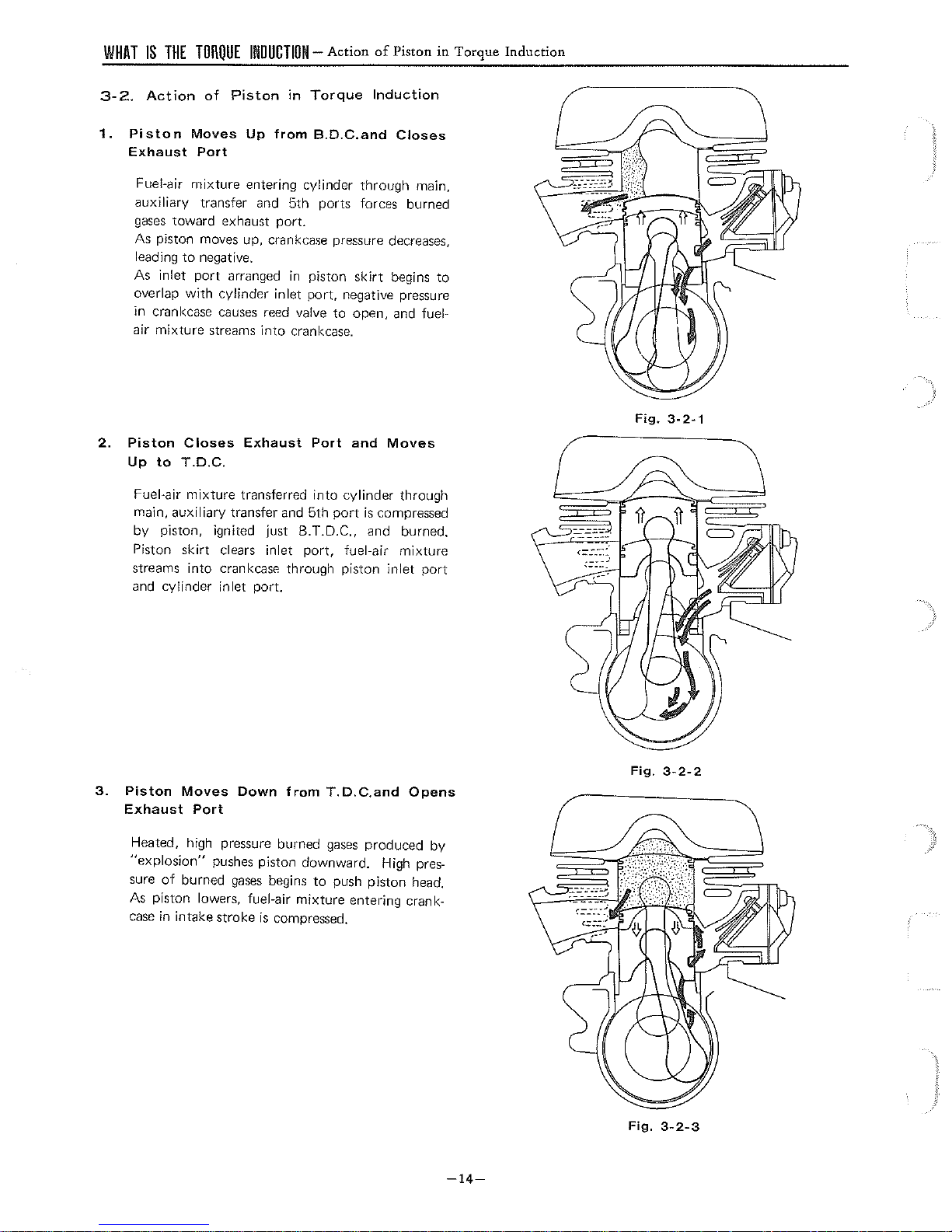
1.
Piston
Exhaust
IS
THE
Action
TORQUE
Moves
Port
INDUCTION-
of
Piston
Up
in
from
Action
Torque
B.D.C.and
of
Piston
Induction
Closes
in
Torque
Induction
Fuel-air
auxiliary
gases
As piston moves up, crankcase pressure decreases,
leading
As inlet
overlap
in crankcase
mixture
toward
to
port
with
entering cylinder
transfer and 5th ports forces burned
exhaust
negative.
arranged
cylinder inlet
causes
port.
in
piston
port,
reed valve
through
skirt
negative pressure
to
open, and fuel-
air mixture streams into crankcase.
2.
Piston
Up
Fuel-air
main, auxiliary transfer
by
Piston
streams
and cylinder inlet port.
Closes
to
T.D.C.
mixture
piston, ignited just B.T.D.C., and burned.
skirt
into
Exhaust
transferred
clears inlet
crankcase through piston
and
Port
into
5th
port,
and
cylinder
port
is
fuel-air
main,
begins
to
Moves
through
compressed
mixture
inlet
port
Fig.
3-2-1
3.
Piston
Exhaust
Heated, high pressure burned
"explosion"
sure
As piston lowers, fuel-air
case
Moves
of
burned
in intake stroke
Down
Port
pushes piston downward. High
gases
from
begins
mixture
is
compressed.
to
T.D.C.and
gases
push piston head.
entering crank-
Opens
produced by
pres-
-14-
Fig.
Fig.
3-2-2
3-2-3
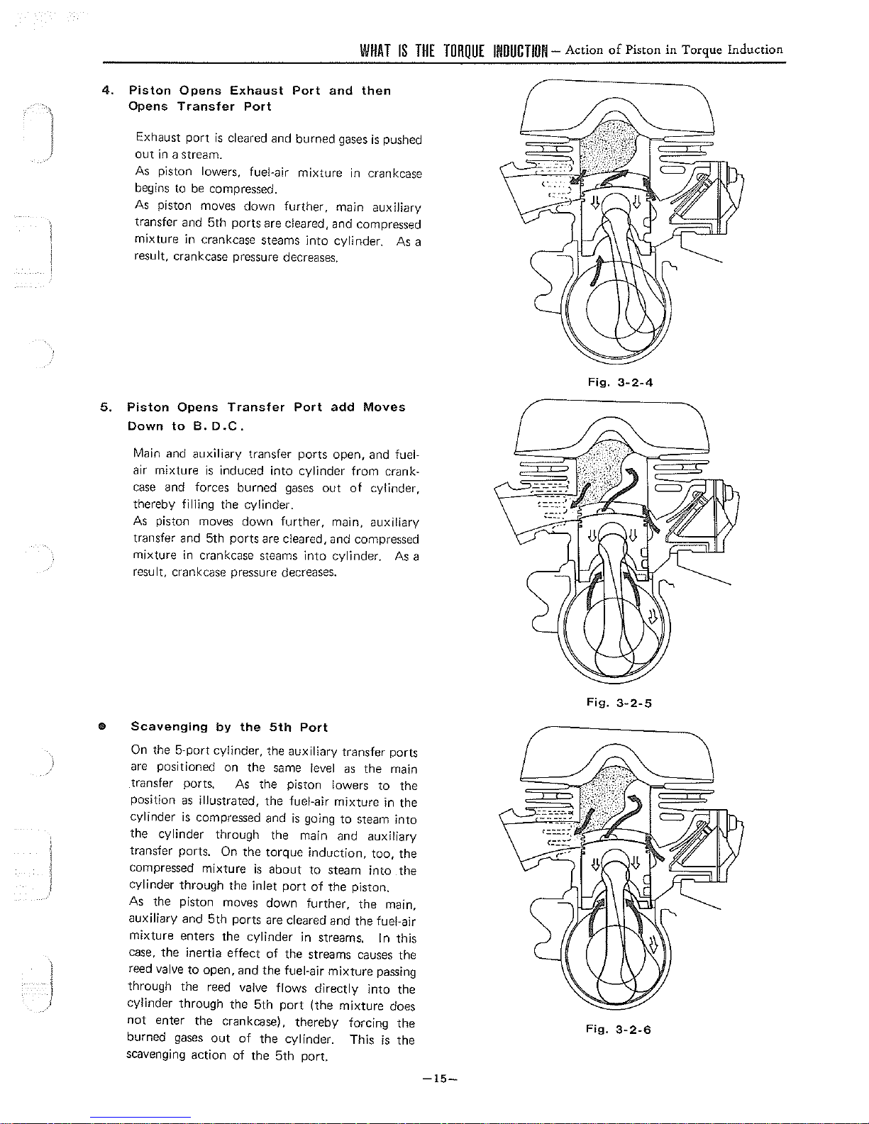
4.
Piston
Opens
Opens
Transfer
Exhaust
Port
Port
and
WHAT
IS
then
THE
TORQUE
INDUCTION-
Action
of
Piston
in
Torque
Induction
Exhaust
out
As
begins to
As
transfer and
mixture
port
is
cleared
in
a stream.
piston lowers, fuel-air
be
compressed.
piston moves down further, main auxiliary
5th
ports
in crankcase steams
result, crankcase pressure decreases.
5.
Piston
Down
Main and
air
case
thereby filling the cylinder.
As
transfer and 5th
mixture
Opens
to
mixture
and forces burned
piston moves down
Transfer
8.
D.C.
auxiliary
is
induced
transfer ports open, and fuel-
ports
in
crankcase steams into cylinder.
result, crankcase pressure decreases.
and
burned
mixture
gases
is
pushed
in crankcase
are cleared, and compressed
into
cylinder. As a
Port
add
Moves
into
cylinder
gases
further,
from
crank-
out
of
cylinder,
main, auxiliary
are cleared, and compressed
As
Fig.
3-2-4
a
e
Scavenging
On
the
are positioned on
transfer ports. As
position as illustrated,
cylinder
the
cylinder through
transfer ports. On
compressed mixture
cylinder through
As
the
auxiliary and
mixture enters
case,
the
reed valve
through the
J
cylinder through the 5th
not
enter
burned gases
scavenging action of
by
the
5th
5-port cylinder,
is
compressed and
the
auxiliary transfer ports
the
same level as
the
piston lowers
the
fuel-air mixture
is
the
the
torque
is
about
the
inlet
port
piston moves down further,
5th
ports
are cleared and
the
cylinder
inertia
effect
of
the
to
open, and
reed
the
out
the
valve
flows
crankcase),
of
the
the
5th
fuel-air
port
cylinder.
Port
the
main
to
in
going
to
steam into
main and auxiliary
induction,
to
steam into
of
the
in
streams.
too,
piston.
the
the
fuel-air
In
main,
this
streams causes
mixture
directly
(the
thereby
into
mixture
forcing
This
passing
does
the
is
the
port.
the
the
the
the
the
the
-15-
Fig.
Fig.
3-2-5
3-2-6
ENBINE
- Engine Removal
CHAPTER
This
chapter
of
the engine, its removal
necessary service data. However,
hauling the crankshaft assembly, transmission, shifter
mechanism, or bearings and oil
it
is
suggested
it
from
labor.
Preparation
1)
All
be
engine assembly
This
from
2)
Before engine removal and disassembly,
you
you
3)
During disassembly
and place them in trays in order
This
and insure correct installation
describes
the
disassembly
from
the
and
chassis,
except
seals
in the crankcase,
that
engine
be
serviced
the
chassis. This will save a
for
disassembly
dirt,
mud, dust, and foreign material should
thoroughly
will
entering the
have
can
will
removed
before
prevent any harmful foreign material
proper tools and deaning equipment
perform a clean and
make assembly
from
removal
interior
of
the engine, clean all parts
without
lot
of
the
the
and
of
the engine assembly.
efficient
time
faster and easier,
of
all engine parts.
reassembly
and the
when
removing
of
time
engine
exterior
disassembly.
be
job.
of
disassembly.
of
over-
and
:
the
sure
so
4.
ENGINE
2.
Remove the
1) Remove the exhaust pipe
pipe ring
Remove the
2)
muffler
muffler.
nut
at one side.
wrench.
Fig.
4-1-2
muffler
nut
with
exhaust
holding bolts and set the
4-1.
1.
Start the engine
then
oil.
Volume
Engine
turn
off
of
Removal
a·nd
warm
the engine
Fig.
4-1-1
oil:
500 c.c. (0.53
(SAE
it
up
for a few
and
drain the transmission
US
qts.)
l0W/30)
minutes,
3.
Remove the change pedal.
Fig.
4-1-3
-16-
Fig.
4-1-4

ENGINE
- Engine Removal
4.
Remove
5.
Remove the flywheel magneto.
a.
the
lefthand crankcase cover.
Remove the
holding
tool.
Fig.
nut,
4-1-5
using a flywheel magneto
c.
Remove the
magneto
the flywheel
6.
Remove the
It
is
advisable
flywheel magneto {using its magnetic force), which
the key
is
removed
two
base
base.
Fig.
woodruff
to
place the
for
screws holding the flywheel
to
the crankcase, and remove
4-1-8
key.
woodruff
engine service.
key on the
Fig.
4-1-6
b. Install the flywheel magneto puller.
left and the flywheel magneto
Fig.
4-1-7
will
break loose.
Turn
it
-17-
7.
Disconnect the master
Fig.
Fig.
4-1-9
link
4-1-10
and remove the chain.
 Loading...