

Page 1

OWNER'S
MANUAL
/
OPERATOR
GOLF CAR G22E
,
S
LIT-19626-00-79
JU2-F8199-12
Page 2

INTRODUCTION
Congratulations on your purchase of a
Yamaha golf car. This manual contains
information you will need for proper operation, maintenance, and care of your golf
car. A thorough understanding of these
simple instructions will help you to obtain
maximum enjoyment from your new
Yamaha.
If you have any questions about the operation or maintenance of your golf car,
please consult a Yamaha dealer.
YAMAHA MOTOR MANUFACTURING
CORP OF AMERICA
G22E
OWNER’S/OPERATOR’S
MANUAL
© 2004 by Yamaha Motor
Manufacturing Corporation
of America
1st edition
All rights reserved. Any reprinting
or unauthorized use without the
written permission of
Yamaha Motor Manufacturing
Corporation of America
is expressly prohibited.
Printed in U.S.A.
P/N LIT-19626-00-79
G22E
i
Page 3
IMPORTANT MANUAL
WARNING
NOTE:
NOTE:
CAUTION
WARNING
!
INFORMATION
Particularly important information is
distinguished in this manual by the
following notations:
The Safety Alert Symbol means
ATTENTION! BE ALERT! YOUR
SAFETY IS INVOLVED!
Failure to follow WARNING instructions could result in severe injury
or death to the golf car
occupants, a bystander, or a
person inspecting or repairing
the golf car.
● Yamaha continually seeks ad-
vancements in product design and
quality; therefore, while this manual
contains the most current product
information available at the time of
printing, there may be minor
discrepancies between your golf
car and this manual. If you
have any questions concerning this
manual, please consult your
Yamaha dealer.
● This manual should be considered
a permanent part of your golf car
and should remain with the car
when resold.
This message describes special
precautions that must be taken to
avoid damage to the golf car.
This message provides additional key
information.
ii
Read and understand this manual
completely before operating your
golf car.
G22E
Page 4
CONTENTS
WARRANTY
IMPORTANT LABELS 2
OPERATOR SAFETY 3
MAINTENANCE SAFETY PROGRAM 4
CONTROLS 5
PRE-OPERATION CHECKS 6
OPERATION 7
MAINTENANCE 8
1
1
STORAGE
SPECIFICATIONS
WIRING 11
G22E
iii
9
10
Page 5

WARRANTY
1
YAMAHA MOTOR MANUFACTURING
CORPORATION OF AMERICA
2
Yamaha Motor Manufacturing of America hereby warrants that any new Yamaha Golf Car (gas and electric
models) purchased from an authorized Yamaha dealer
in the United States will be free from defects in material
3
and workmanship for THREE years from date of purchase, subject to the stated limitations.
DURING THE PERIOD OF WARRANTY any authorized Yamaha Golf Car Dealer will, free of charge, repair
4
or replace, at Yamaha’s option, any part adjudged
defective by Yamaha due to faulty workmanship or
material from the factory. Parts used in warranty repairs
will be warranted for the balance of the machine’s warranty period. All parts replaced under warranty become
5
property of Yamaha Motor Manufacturing Corporation of
America.
GENERAL EXCLUSIONS from this warranty shall
include any failures caused by:
6
a. Abnormal strain, neglect, or abuse, including lack of
proper maintenance, and use contrary to the
Owner’s/Operator’s Manual instructions.
b. Accident or collision damage.
c. Installation of parts or accessories that are not
7
8
9
10
11
original equipment.
d. Fading, rust, or deterioration due to exposure or
ordinary wear and tear.
e. Modifications or alteration that affects the car’s
condition, operation, performance, or durability, or
which makes the car serve a purpose other than use
as a two-person, golf course vehicle.
f. Damage due to improper transportation.
g. Acts of God, ie: lightning, hail damage, flooding, fire,
etc.
SPECIFIC EXCLUSIONS: The first year of warranty
shall cover the entire car except for batteries, battery
chargers, tires and rims, which are warranted by their
respective manufacturers. Parts excluded from the second year of warranty include the body parts, seats,
mats, bumper assembly, bag carrier, scorecard holder,
and the trim. Parts excluded from the third year of warranty include the second year exclusions, the electrical
system (except electronic speed controller and electric
motor) and control cables. Other specific exclusions
from this warranty shall include any parts replaced due
to normal wear or routine maintenance, including oil, air
filter elements, brake shoes, spark plugs, starter and
clutch drive belts. Any charges incurred in transporting
a golf car to and from an authorized Yamaha Golf Car
Dealer for service or in performing field service are also
excluded from this warranty.
LIMITED 3-YEAR
GOLF CAR WARRANTY
1-1
G22E
Page 6
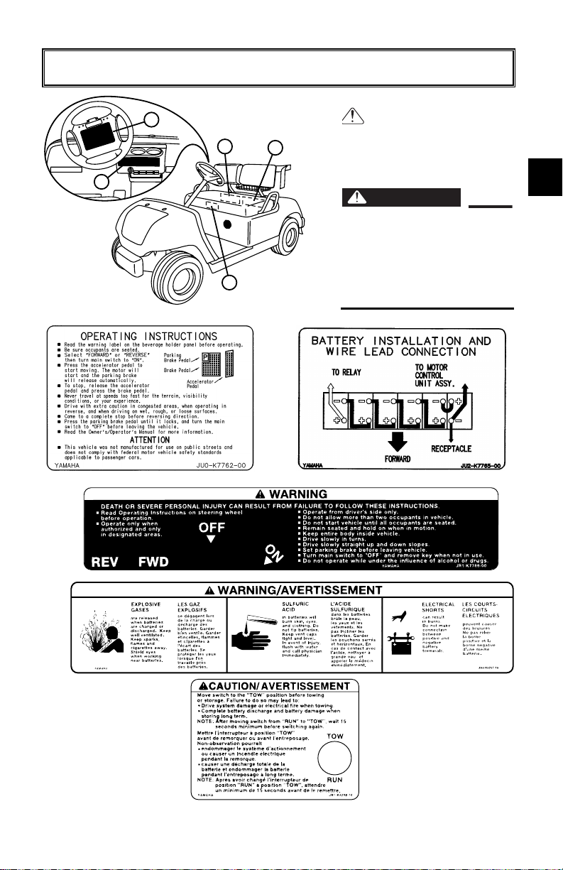
IMPORTANT LABELS
Y-844
WARNING
1
2
1
3
4
SAFETY AND
INSTRUCTION
1
LABELS
2
Please read the following
labels carefully before
operating your golf car, and
Y-654a
5
promptly replace any labels
which become damaged or
removed.
3
2
3
4
5
6
7
Y-500
Y-655
8
4
G22E
5
Y-656
Y-843
2-1
9
10
11
Page 7
IMPORTANT LABELS
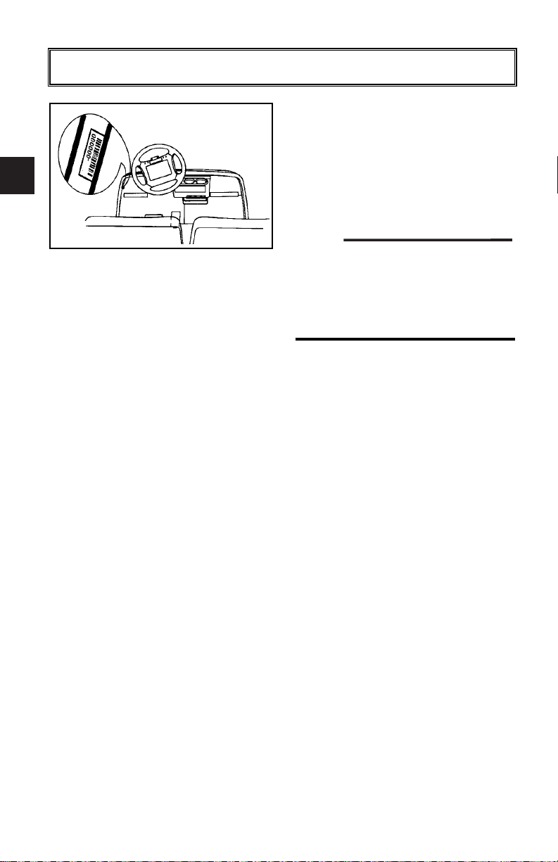
NOTE:
1
2
3
JU2
Y-102b
4
NUMBER
The golf car serial number is stamped
in the location shown.
The first three digits of the serial number are for model identification; the
remaining digits are the unit production number. Keep a record of these
numbers for reference when ordering
parts from a Yamaha dealer.
5
6
7
8
GOLF CAR SERIAL
9
10
11
2-2
G22E
Page 8
OPERATOR SAFETY
Y-67
!
Y-8
Y-68
Yamaha golf cars are designed to be
simple to operate. However, be sure
to observe the following:
BEFORE OPERATING
THE GOLF CAR
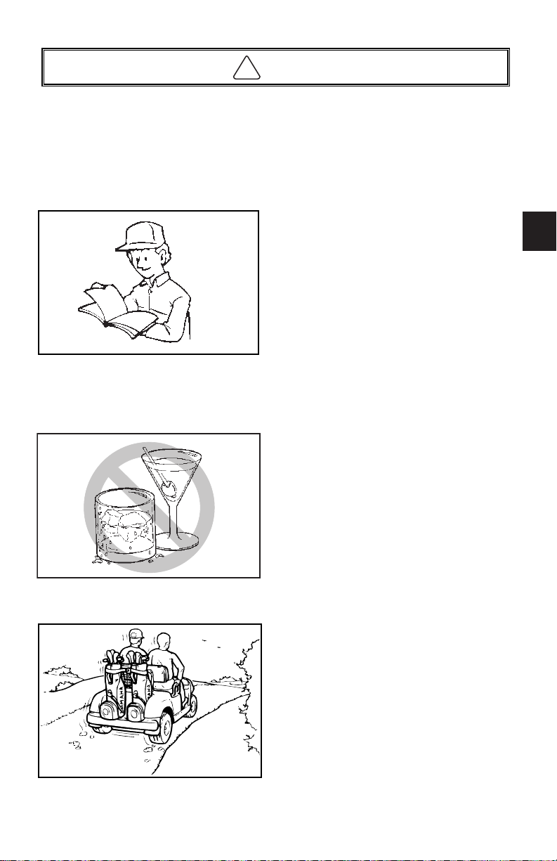
● Read this Owner’s/Operator’s man-
ual and all safety and instruction
labels on the golf car before operating.
● Perform the pre-operation checks
found in Section 6 of this manual.
● Only authorized people should
drive the golf car, from the driver’s
side only, and only in designated
areas.
● Do not allow more than two people
to ride in the golf car. This golf car is
restricted to two occupants.
● Do not operate the golf car while
under the influence of alcohol or
drugs; their affect on vision and
judgment make operating a golf car
dangerous.
● Do not operate the golf car on pub-
lic streets, roads or highways. Such
use is prohibited by law, and dangerous. Operation on public roads
can result in collision with other
vehicles.
1
2
3
4
5
6
7
8
9
10
G22E
WHILE OPERATING THE
GOLF CAR
● Keep your entire body inside the
golf car, remain seated, and hold on
when the car is in motion.
● Do not start the golf car until all
occupants are seated.
3-1
11
Page 9
!
OPERATOR SAFETY
1
2
3
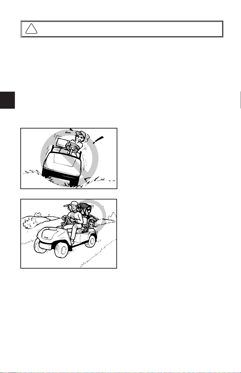
● Keep your hands on the steering
wheel and your eyes on the path
ahead.
● Use extra care in congested areas
or when backing up. Always back
up slowly, and watch carefully.
● Avoid starting or stopping abruptly.
● Vary the speed of the golf car to
match the terrain of the course.
4
● Avoid turning the steering wheel too
sharply at higher speeds.
5
● Always drive slowly straight up or
straight down slopes – never at an
angle.
6
Y-10
7
8
● Do not make any modification or
addition which affects capacity or
safe operation, or make any
changes not in accordance with the
owner’s/operator’s manual.
9
10
11
3-2
Y-69
G22E
Page 10

!
GOLF COURSE SAFETY PROGRAM
Like all machines, golf cars can
cause injury if improperly used or
maintained. This section contains
broad safety practices required for
safe golf car operation. Before golf
cars are operated, golf course personnel should establish any additional safety practices that may be
required for safe operation.
Experience has shown that golf cars
are safe when operated in accordance with the safety warnings
affixed to every golf car. This safe
operation is enhanced when golf cars
are used according to the safety rules
and practices established to meet the
terrain and conditions of the course
they are used on.
The information contained here is
intended for golf course personnel
responsible for golf car safety. If you
are responsible for the operation and
maintenance of this golf car, we
encourage you to implement this golf
car safety program.
Do Not Operate Golf Cars When
Under The Influence Of Alcohol Or
Drugs
GOLF COURSE SAFETY
SURVEY
Perform safety surveys regularly to
identify hazardous areas where golf
cars should not be operated.
GOLF COURSE HAZARD
PREVENTION
The following golf course hazards
must be made safe:
● Steep Grades. Where steep
grades exist, restrict golf cars to
designated golf car pathways
where possible. In addition, identify
steep grades with a suitable warning like:
Warning: Steep Grade, Descend
Slowly With Foot On Brake
1
2
3
4
5
6
7
8
DRIVER
QUALIFICATIONS
Allow only authorized people to operate golf cars. It is recommended that
only people who possess a valid
motor vehicle driver’s license be
allowed to operate golf cars.
Place operation and safety instructions recommended by the golf car
manufacturer, along with the golf
course safety rules, in a conspicuous
place near the golf car rental area or
golf car pick-up area. It is also recommended that the following warning
be posted in a conspicuous location:
G22E
● Sharp Turns, Blind Corners,
Bridge Approaches. Chain or
rope off these potentially hazardous areas or identify them with
a suitable warning describing the
nature of the hazard and the proper precautions to be taken to avoid
the hazard.
● Wet Areas. Wet grass may cause
a golf car to lose traction and may
affect stability. Chain or rope off wet
areas or identify wet areas with a
suitable warning.
4-1
9
10
11
Page 11

GOLF COURSE SAFETY PROGRAM
!
● Loose Terrain. Loose terrain may
1
2
3
4
5
cause a golf car to lose traction and
may affect stability. Repair loose
terrain, chain or rope off these
areas, or identify loose terrain with
a suitable warning.
● Golf Car and Pedestrian Interfer-
ence. Reroute golf car traffic or
pedestrian traffic in congested
areas wherever possible to prevent
accidents. If it is impractical to
reroute traffic, erect warning signs
to warn pedestrians of golf car traffic, and to warn golf car operators to
drive slowly, use caution, and watch
for pedestrians.
MAINTENANCE
6
REQUIRED FOR GOLF
CAR SAFETY
Practice the following to help ensure
7
the safety of golf car occupants:
● Preventative Maintenance. Per-
8
9
form all scheduled maintenance in
accordance with manufacturer’s
recommendations to provide the
golfing patron with a safe, properly
operating golf car.
● Ventilation. Properly ventilate all
maintenance and storage areas in
accordance with applicable fire
codes and ordinances to avoid fire
hazards. Ventilation is required to
remove hydrogen gas from electric
powered car storage areas during
the charging process.
For electric powered golf cars, the
amount of hydrogen gas emitted during charging depends on a number of
factors, such as the condition of the
batteries, the output rate of the battery charger, and the amount of time
the batteries are on charge. Because
of the highly volatile nature of hydrogen gas and its propensity to rise and
accumulate at the ceiling in pockets, a
minimum of 5 air changes per hour is
recommended. Consult applicable
fire and safety codes for the specific
ventilation levels requirement, as well
as requirements for the use of explosion proof electrical apparatus.
● Personnel. Allow only qualified,
10
11
trained, and authorized personnel
to inspect, adjust, and maintain golf
cars.
● Parts and Materials. Use only
replacement parts and materials
recommended by the manufacturer.
4-2
G22E
Page 12

!
GOLF COURSE SAFETY PROGRAM
SAFETY PRECAUTIONS
DURING MAINTENANCE
When performing maintenance, follow all safety instructions contained
in the manufacturer’s operation and
service manuals, as well as the following safety procedures:
● Properly immobilize golf car before
beginning any maintenance.
● Properly block chassis before
working underneath golf car.
● Avoid fire hazards, and have
appropriate fire protection equipment available.
● Before working on an electric golf
car, disable the car’s electrical system in accordance with the manufacturer’s instructions.
● Use only properly insulated tools
when working on electrically powered golf cars or around batteries.
● Maintain all safety devices includ-
ing brakes, steering mechanisms,
warning devices, and governors, in
a safe operating condition. Do not
modify these safety devices as
supplied by the manufacturer.
● After each maintenance or repair,
the car must be driven by a qualified, trained, and authorized person – in an area free of pedestrian
traffic – to ensure proper operation
and adjustment.
● Record all maintenance performed
in a maintenance record log by
date, name of person performing
maintenance, and type of maintenance. Periodically inspect maintenance log to ensure accurate and
complete entries.
● Provide operator comment cards to
assist in identifying non-periodic
maintenance needs for specific golf
cars.
● Maintain in a legible condition all
nameplates, warnings, and instructions provided by the manufacturer.
● If new nameplates, warnings, or
instructions are needed, contact
your Yamaha dealer.
STORAGE AND
BATTERY CHARGING
Ta ke the following precautions to
ensure maintenance worker safety:
● Only use battery changing and
charging facilities and procedures
that are in accordance with applicable ordinances and regulations.
● Periodically inspect charging facili-
ties and procedures to be certain
that applicable safety codes, regulations, and procedures are being
followed.
1
2
3
4
5
6
7
8
9
10
11
G22E
4-3
Page 13

CONTROLS
1
6
5
2
4
P
3
1
7
8
Y-6 59a
FEATURES
1 Steering wheel
2 Seat
3 Batteries
4 Brake pedal
5 Parking brake pedal
6 Accelerator pedal
7 Main switch
8 Drive selector switch
9 Tow switch
4
a Front cowl
b Front tire
c Front bumper
5
d Rear cowl
e Rear bumper
f Rear tire
16
3
Y-658
g Receptacle
6
7
8
2
10
11
13
9
10
11
5-1
14
12
Y-660
9
CAUTION / AVERTISSEMENT
Y-6 62a
15
Y-661
G22E
Page 14

CONTROLS
REV FWD
REV FWD
MAIN SWITCH
The main switch controls the following items:
OFF
Ignition circuit is switched off.
The key can be removed only in this
OFF
ON
position.
1
2
3
4
Y-663
ON
Electrical circuits are switched on.
The golf car can be driven.
OFF
ON
5
6
7
8
Y-664
G22E
9
10
11
5-2
Page 15

NOTE:
CONTROLS
1
OFF
2
REV FWD
ON
3
Y-665
DRIVE SELECT SWITCH
The drive select switch is used to
shift the golf car into forward or
reverse. After coming to a complete
stop, move the switch to the desired
position.
Switch Position Car Movement
FWD FORWARD
REV REVERSE
4
5
The back-up buzzer will beep when
the drive select switch is depressed
to the “REV” position.
6
Y-19
7
ACCELERATOR PEDAL
A
8
The accelerator pedal controls the
golf car’s speed.
9
10
11
5-3
Action Car Speed
Depress pedal Increase
Y-20A
Release pedal Decrease
å Accelerator pedal
BRAKE PEDAL
Press down on the brake pedal to
stop the golf car.
∫ Brake pedal
B
Y-21a
G22E
Page 16

NOTE:
WARNING
NOTE:
CONTROLS
A1
F2
C
CAUTION / AVERTISSEMENT
PARKING BRAKE
PEDAL
Press down on the parking brake
pedal whenever parking the golf car.
ç Parking brake pedal
Y-22a
Release the parking brake by
depressing the accelerator pedal.
1
2
3
4
The parking brake will automatically
release when the accelerator pedal
is depressed. If the main switch is in
the “ON” position, depressing the
accelerator may suddenly cause the
golf car to move.
5
6
7
TOW SWITCH
Before operating the car, make sure
TOW
RUN
A
the tow switch is in the “RUN” position.
å Tow switch
8
9
G22E
Anytime the tow switch is moved from
Y-666a
the “RUN” position to the “TOW” position and immediately moved back to
“RUN”, there is a delay of approximately 30 seconds before the car will
run.
Make sure the tow switch is in the
“TOW” position if towing this vehicle.
10
11
5-4
Page 17

PRE-OPERATION CHECKS
WARNING
1
2
Pre-operation checks should be
made each time you use your golf
car. Get in the habit of performing the
following checks in the same way so
that they become second nature.
3
● Be sure the main switch key is
removed before performing the
4
pre-operation checks to prevent
accidental starting, and apply
the parking brake to keep the car
from moving.
5
PRE-OPERATION
6
7
8
CHECKLIST
Before each use check the following:
✔ Batteries
✔ Tire condition
✔ Steering system
✔ Back-up buzzer
✔ Pedal operation
✔ Body and chassis
9
10
11
6-1
SEAT
Open the seat for checking and servicing.
Y-512
G22E
Page 18

PRE-OPERATION CHECKS
BATTERY
Charge batteries before each use.
See charging steps in chapter 8,
Maintenance.
Check that the batteries are held securely
in place to prevent the batteries from
being damaged from vibration or jarring.
Also check that no battery caps are
missing to prevent battery acid from
spilling from the battery. Check the
battery terminals for corrosion.
TIRE CONDITION
Tire Air Pressure
Check the tire air pressure before
operating the golf car.
Tire pressure:
20 psi
(137 kPa, 1.4 kgf/cm2)
1
2
3
4
5
6
7
8
G22E
Y-30
9
Tire Wear Limit
A
Y-31
Check the tire surface for damage,
cracks or embedded objects. When
tire tread wears down to 0.04 in. (1
mm), replace the tire.
å Wear limit
10
11
6-2
Page 19

PRE-OPERATION CHECKS
1
2
3
4
Y-667
5
6
REV FWD
OFF
ON
STEERING SYSTEM
Check the steering system for excessive freeplay by:
● moving the steering wheel up and
down, and back and forth.
● turning the steering wheel slightly
to the right and left.
If you feel excessive freeplay, or hear
rattling sounds which may indicate
loose steering components, consult a
Yamaha dealer.
BACK-UP BUZZER
Check the back up buzzer by moving
the drive select switch to “REV” for
reverse. The buzzer should sound.
7
8
Y-668
PEDAL OPERATION
9
10
11
6-3
Check the following pedal controls for
proper operation. If a pedal does not
work properly, consult a Yamaha
dealer.
Brake Pedal
Make sure the brake pedal feels firm
when pressed and returns to its original position when released.
∫ Brake pedal
B
Y-21a
G22E
Page 20

PRE-OPERATION CHECKS
WARNING
NOTE:
Parking Brake Pedal
Make sure the parking brake pedal
locks in place with a positive click,
and releases when the accelerator
pedal is pressed.
C
Y-22a
ç Parking brake pedal
Release the parking brake by
depressing the accelerator pedal.
1
2
3
4
Accelerator Pedal
5
Before checking operation of the
accelerator pedal, be sure the
main switch is in the “OFF” position.
Make sure the accelerator pedal
A
operates smoothly.
å Accelerator pedal
6
7
8
G22E
Y-20A
BODY AND CHASSIS
Before each use, visually inspect the
golf car body and chassis for damage
and/or missing parts.
6-4
9
10
11
Page 21

OPERATION
NOTE:
WARNING
CAUTION
1
OFF
2
REV FWD
ON
3
Y-665
STARTING
1. With the parking brake applied,
turn the drive select switch to
“FWD” for forward, or “REV” for
reverse.
Do not shift from “FWD” forward
to “REV” reverse while the golf car
is moving.
4
2. Turn the main switch to “ON.”
5
OFF
REV FWD
ON
6
7
8
Y-664
A
9
Do not depress the accelerator
pedal when turning on the main
switch or the golf car may suddenly start moving.
3. Check that your path is clear in
the direction you plan to go, and
slowly depress the accelerator
pedal. The golf car will start to
move.
10
11
7-1
å Accelerator pedal
Y-20A
The parking brake automatically
releases when the accelerator pedal
is depressed.
G22E
Page 22

OPERATION
CAUTION
STOPPING
To stop the golf car, gradually press
down on the brake pedal.
∫ Brake pedal
When the car has come to a stop,
C
apply the parking brake pedal and
turn the main switch to “OFF.”
ç Parking brake pedal
1
2
3
4
B
Y-65a
Do not hold the golf car on an
incline with the accelerator – use
the brake.
5
6
7
8
G22E
9
10
11
7-2
Page 23

MAINTENANCE
1
Regular maintenance is required for the best performance and safe operation of
your golf car.
2
3
WARNING
Be sure to turn off the main switch and apply the parking brake when you perform
maintenance unless otherwise specified. If the owner is not familiar with machine
servicing, this work should be done by a Yamaha dealer or other qualified
mechanic.
PERIODIC MAINTENANCE CHARTS
4
5
6
7
8
9
10
11
8-1
G22E
Page 24

MAINTENANCE
FOR G22E
C - CHECK CA - CHECK AND ADJUST R - REPLACE S - SERVICE CL - CLEAN AND LUBRICATE L - LUBRICATE
PRE-OP
EVERY
MONTH
EVERY 6
MONTHS
EVERY
YEAR
EVERY 4
YEARS
Charge
Clean battery tops, check for
tightness of hold-down screws and
terminals
Check brake pedal freeplay and
adjust if necessary
Check steering operation
Check tire pressure, tread depth,
tire surface for damage
Check body and chassis for
damage
Check tightness of all bolts, nuts,
and screws
Check reverse buzzer operation
Check electrolyte level
Check for loose or broken
connections
Clean/Lube pedal control area
Check all wire insulation for cracks
and/or worn spots
Check shock absorbers for oil leaks
and damaged springs
Perform a discharge test
Apply Terminal protectant
Check shoe lining thickness and
rear axle bearing play
Check steering knuckle
bushing freeplay / Adjust
wheel alignment
Check wheel nut tightness, front
wheel bearing play
Check gear box oil level and
leakage
Check operation and adjust pedal
stop if necessary
Replace gear box oil
Check for grease leakage; adjust
gear box if necassry
Items without a page number reference should be serviced by a Yamaha dealer or other qualified mechanic. This manual does
*
not contain these procedures. They are contained in the Service Manual.
Pre-
20 rounds 125 rounds 250 rounds 500 rounds 1000 rounds
Operation
S
S
C
C
C
C
C
C
20 hours
100 miles
160 kms
(Every
Month)
S
S
CA
C
CA
C
C
C
C
C
CL
600 mls
1000 kms
(Every 6
months)
125 hrs
S
S
CA
C
CA
C
C
C
C
C
C
C
250 hrs
1200 mls
2000 kms
(Every
Year)
S
S
CA
C
CA
C
C
C
C
C
C
C
S
S
C
CA
C
C
CA
500 hrs
2500 mls
4000 kms
(Every 2
years)
S
S
CA
C
CA
C
C
C
C
C
C
C
S
S
C
CA
C
C
CA
1000 hrs
5000 mls
8000 kms
(Every 4
years)
S
S
CA
C
CA
C
C
C
C
C
C
C
S
S
C
CA
C
C
CA
R
CA
PageRemarks
8-5
8-3/
6-2
8-9/
8-10
6-3
6-2
6-4
*
6-3
8-3/8-4
*
—
*
*
*
—
*
*
8-9/
8-8
*
*
8-8
1
2
3
4
5
6
7
8
9
*
10
11
G22E
8-2
Page 25

MAINTENANCE
CAUTION
WARNING
1
2
3
4
5
6
7
8
9
10
11
Battery Care
Battery electrolyte is poisonous and
dangerous, causing severe burns,
etc. It contains sulfuric acid. Avoid
contact with skin, eyes, or clothing.
Antidote:
EXTERNAL: Flush with water.
INTERNAL: Drink large quantities of
water or milk. Follow with milk of
magnesia, beaten egg, or vegetable
oil. Call physician immediately.
EYES: Flush with water for 15
minutes and get prompt medical
attention.
Batteries produce explosive gases.
Keep sparks, flame, cigarettes, etc.,
away.
Ventilate when charging or using in
enclosed space. Always shield eyes
when working near batteries.
KEEP OUT OF REACH OF CHILDREN.
Six 8-volt deep cycle batteries provide
power for your electric golf car and
must be properly maintained and
recharged for maximum performance
and service life.
To maintain your batteries:
1. Clean the tops of the batteries
with a solution of baking soda and
water, as necessary, to remove
corrosion.
8-3
Do not allow cleaning solution to
enter battery cells.
2. Check the fluid level before and
after charging.
G22E
Page 26

MAINTENANCE
CAUTION
● Before charging: only add distilled
water if fluid is below the top of the
plates, and then add just enough to
cover plates.
● After charging: check that the fluid
level is approximately 1/4 to 1/2 inch
above the plates and 1/4 to 3/8 inch
below the level indicator. If the fluid
level is low, carefully add distilled
water. Adding distilled water after
charging helps prevent boil over.
D
A
C
B
Y-829
å Battery cap
∫ Plates
ç Maximum fluid level
∂ Minimum fluid level
Normal tap water contains minerals which are harmful to a battery;
therefore, refill only with distilled
water.
1
2
3
4
5
6
7
3. Using a hydrometer, check the
specific gravity of the battery fluid
Y-47
in each cell against the readings
on the chart below. Consult a
Yamaha dealer if any low readings
are found, or if readings vary more
than one point between cells.
Temperature
˚F ˚C
120 48.9 1.244
110 43.3 1.248
100 37.8 1.252
90 32.2 1.256
80 26.7 1.260
70 21.1 1.264
60 15.6 1.268
50 10.0 1.272
40 4.4 1.276
30 -1.1 1.280
Satisfactory Uncorrected
Hydrometer Reading
8
9
10
11
G22E
8-4
Page 27

MAINTENANCE
CAUTION
WARNING
WARNING
REV FWD
OFF
ON
Y-663
1
2
Battery Charging
Read and understand the owner’s
manual provided with your golf
car’s battery charger before charging batteries.
3
4
5
6
7
8
Explosive hydrogen gas is produced while batteries are being
charged. Only charge batteries in
well ventilated areas (a minimum
of 5 air changes per hour is recommended).
To charge the batteries in your golf
car, follow the instructions contained
in your battery charger’s owner’s
manual.
The following is a summary of the
charging steps. Do not attempt to
recharge your golf car’s batteries
without thoroughly reading and
understanding the owner’s manual
provided with your charger.
9
10
11
8-5
1. Turn main switch key to “OFF”
position.
2. With the charger properly connected and grounded (see charger’s owner’s manual), insert the
DC output plug into the golf car
receptacle.
Y-669
Use only battery chargers that are
rated for use with 48 volt Yamaha
Golf Cars. Thoroughly read and
understand the user manual
supplied with your 48 volt charger.
G22E
Page 28

MAINTENANCE
WARNING
WARNING
Do not disconnect the DC output
cord from the battery receptacle
when the charger is on or an arc
could occur that may cause an
explosion.
3. The charger will turn off automatically when the batteries reach
full charge.
4. After the charger has turned off,
disconnect the DC output plug
from the golf car receptacle by
grasping the plug body and
pulling the plug straight out of the
receptacle.
Battery Installation
1
2
3
4
5
6
C
B
G22E
When working with batteries, do
not put wrenches or other metal
objects across the battery terminals. An arc can occur causing
explosion of the battery.
A
1. Install the battery holddown
plates as shown.
å Forward
∫ Battery
ç Battery fitting plate
7
8
9
10
11
Y-7 51a
8-6
Page 29

MAINTENANCE
CAUTION
WARNING
CAUTION
WARNING
B
A
-
+
-
+
-
+
-
+
-
+
-
+
D
C C
FORWARD
Y-653
B
A
1
2. Connect the wire leads as shown.
å Forward
∫ To receptacle
2
ç To motor control unit
∂ Between batteries
To relay
3
4
5
6
7
When installing batteries:
● Carefully place battery cables
and holddowns making sure that
cables do not lay across vent
caps.
● Always remove the negative (–)
cable to the motor controller first,
and install it last.
Do not overtighten the battery
holddown nuts. Excessive force
will damage the battery casing.
8
9
10
11
Fuse Type:
8-7
3 Amp, Blade Style
Fuse Replacement
Be sure to use the specified fuse.
Using a wrong fuse can cause
electrical system damage and create a fire hazard.
When replacing a fuse be sure the
main switch is turned off to prevent accidental short-circuiting.
å Fuse case
∫ Fuse
G22E
Page 30

MAINTENANCE
NOTE:
CAUTION
Y-48
Gear Box Oil
To check gear box oil level:
1. Place the golf car on a level sur-
face.
2. Remove the access panel by
removing the rivets in the two
lower corners of the panel and
pulling the panel from the car.
3. Remove the oil level plug å.
1
2
3
4
4. Add gear oil little by little until oil
flows from the level plug hole ∫.
5
Recommended oil:
SAE 90 gear oil
A
B
Y-520A
Gearcase capacity:
0.32 US qt
(300 mL, 300 cc)
6
7
5. Allow excess gear oil to flow out
until it stops.
8
G22E
Do not allow foreign material to
enter the gear box.
6. Reinstall the oil level plug.
For gear oil replacement, consult a
Yamaha dealer or other qualified
mechanic.
8-8
9
10
11
Page 31

MAINTENANCE
WARNING
CAUTION
1
Before performing wheel or brake
maintenance, verify that the main
2
3
switch is in the “OFF” position.
Wheel Replacement
To remove and install a wheel on
your golf car:
4
5
6
7
8
9
10
11
Y-57
1. With the wheels blocked to prevent the golf car from moving,
loosen the wheel nuts.
2. Elevate the golf car with a jack
and remove the wheel nuts and
the wheel.
3. Reverse the removal steps when
installing the wheel.
Wheel nut tightening torque:
58 ft.lb (80 Nm, 8.0 m.kg)
Brake Adjustment
The brakes on your golf car are selfadjusting.
Before you operate the car, press
down on the brake pedal several
times to make sure the brakes are
functioning properly.
Consult your Yamaha dealer
before using your golf car if you
suspect brake problems. Brake
failure could result in a serious
accident.
8-9
G22E
Page 32

MAINTENANCE
WARNING
CAUTION
Brake Pedal Free Play
1
Adjustment
2
Before adjusting brake pedal free
play, pump the brake pedal several
times to self-adjust the brakes.
3
To adjust the brake pedal free play:
1. Remove the service lid from the
floor of the golf car.
4
5
Y-61a
6
2. Check the brake pedal free play
by pressing against the pedal
with two fingers (using light force)
a
18
17
16
15
14
13
12
11
10
9
8
7
and measuring the distance the
pedal travels before resistance is
felt.
7
8
Brake pedal free play Å:
20-25 mm (0.79-0.98 in.)
Y-62b
9
G22E
Y-63
3. If the free play distance needs
adjusting, loosen the lock nut and
turn the adjusting nut in or out
until the free play specification is
met. Then tighten the lock nut in
place.
Do not overtighten the brake
cables. The self adjusters may not
operate properly, reducing braking
performance.
8-10
10
11
Page 33

STORAGE
NOTE:
CAUTION
Perform the following preparations
1
when storing your golf car for extended periods of time:
2
Turn main switch key to “OFF” position, remove key, and store key in a
safe place. Move the tow switch into
the “TOW” position.
3
CHASSIS
4
PREPARATION
1. Verify the tire pressure is set to
5
20 psi (137 kPa, 1.4 kgf/cm2).
2. Clean exterior of the golf car and
apply a rust inhibitor.
6
3. Cover the golf car with a breathable cover and store it in a dry,
well-ventilated area.
7
8
BATTERY
PREPARATION
1. Recharge the batteries and check
the fluid levels at least once a
month.
Do not allow cleaning solution to
enter battery cells.
2. Clean the tops of the batteries
with a solution of baking soda
and water, as necessary, to
remove corrosion.
9
10
11
9-1
G22E
Page 34

SPECIFICATIONS
GENERAL SPECIFICATIONS
Items G22E
Dimensions:
Overall length 93.9 in. (2385 mm)
Overall width 47.2 in. (1200 mm)
Overall height (steering height) 46.9 in. (1190 mm)
Height of floor 11.8 in. (300 mm)
Wheelbase 64.3 in. (1632 mm)
Tread:
Front 34.3 in. (870 mm)
Rear 38.6 in. (980 mm)
Min. ground clearance 3.8 in. (97 mm)
Weight:
Dry weight (without battery) 549 lb (249 kg)
Performance:
Factory speed setting 12 mph (19 km/h)
Maximum speed 15 mph (24 km/h)
Minimum turning radius 114.2 in. (2.9 m)
Seating capacity 2 persons
Hill climbing ability 20°
on pavement
1
2
3
4
5
6
7
8
TRANSMISSION
Items G22E
Differential/reduction gear:
Differential type Bevel gear
Lubricant/capacity SAE 90 gear oil/
0.32 US qt (300 mL,
300 cc)
BATTERIES
Items G22E
Battery: BCI group GC-2H
RC: minimum 105 min
G22E
9
10
11
10-1
Page 35

SPECIFICATIONS
CHASSIS
1
Items G22E
Steering system:
2
3
4
5
6
7
8
9
Type Rack and Pinion
Steering angle (L.H.) 1.55 turn
Steering angle (R.H.) 1.55 turn
Brakes:
Brake system Mechanical drum brake on each rear wheel
Type of brake Dual internal expanding shoe.
Brake pedal freeplay linkage
adjustment 20-25 mm
(Brake cable end play) 0.004-0.02 in. (0.1-0.5 mm)
Parking brake:
Type Foot type; parking brake with automatic
Release timing
(With pedal segment in second notch)
(Bolt heads round parallel to arm) 0.000 ~ 0.001 in. (0.0 ~ 0.3 mm)
Wheel:
Tire size:
Front 18 x 8.50–8.00/4 PR
Rear 18 x 8.50–8.00/4 PR
Rim size: 7.00–I–8.00
Tire pressure: 20 psi (137 kPa, 1.4 kgf/cm2)
with self-adjusters.
Leading/trailing shoes (self-adjusting)
release.
10
11
10-2
G22E
Page 36

G22E WIRING DIAGRAM
Main switch
Tow/storage switch
Accelerator stop switch
Buzzer
Directional switch
DC motor
Controller
Throttle sensor
Relay
Receptacle
Fuse (3A)
123456789
R
R
B/
W
B
W
W
TRANSCEIVER
Y
1
REV FWD
R/Y
32
W R/Y
W R/Y Y
Y
W
5
B
B
P
Br
R/W
P
Br
R/W
BUZZER
OFF ON
Br
R/W
4
3
2
OFF ON
R
R/Y R
R/Y
B/W
B
Y
R/Y
W
B
P
Br
R/W
WR/Y Y
RW
R/W
R/W
RY
101112
B/W
B
R/Y
R/Y
R
R
W
R/Y
W
B
R/Y
Batteries (6 x 8V)
R/W
COLOR CODE
B.....................Black
L.......................Blue
G...................Green
F2
F1
T
A
C
H
B
R
G
GRR
G
BB
B
R
G
19
18
10
236 45
1
1
987
11
R/B
R/Y
R
11
Y...................Yellow
R.......................Red
P.......................Pink
Br...................Brown
W....................White
A2
A1
6
21
20
15
23
14
16
R/B
R/B
Y
R/W
R
3/4 REC
(P) (A1) (A2)
L
BLL
B
L
5KΩ
WIRING
B/R..........Black/Red
Y/B......Yellow/Black
R/Y........Red/Yellow
R/W........Red/White
B/W......Black/White
(F2)
(F1)
ASSY
BOARD
MOSFET
(N)
ASSY
BOARD
CONTROL
B
O
OO
B
O
8
R
R
B
9
12
Y-671
7
1
2
3
4
5
6
7
8
9
10
11
G22E
1
OFF ON
R/W
R
10
11-1
Page 37

NOTES
G22E
Page 38

Printed in U.S.A
2004-KCC
YAMAHA MOTOR
MANUFACTURING CORP.
OF AMERICA
1000 HWY 34 East
Newnan, GA 30265
770-254-4000
 Loading...