

Yamaha FZS6W, FZS8WC Service Manual

FZS6W
4S8-28197-10
SERVICE MANUAL
LIT-11616-20-60
FZS6WC

EAS20050
or unauthorized use without the written
permission of Yamaha Motor Corporation,
FZS6W/FZS6WC
SERVICE MANUAL
©2006 by Yamaha Motor
Corporation, U.S.A.
First edition, Octover 2006
All rights reserved. Any reproduction
U.S.A. is expressly prohibited.
Printed inU.S.A.
P/N LIT-11616-20-60

EAS20070
NOTICE
This manual was produced by the Yamaha Motor Company, Ltd. primarily for use by Yamaha dealers and their qualified mechanics. It is not possible to include all the knowledge of a mechanic in one
manual. Therefore, anyone who uses this book to perform maintenance and repairs on Yamaha
vehicles should have a basic understanding of mechanics and the techniques to repair these types
of vehicles. Repair and maintenance work attempted by anyone without this knowledge is likely to
render the vehicle unsafe and unfit for use.
This model has been designed and manufactured to perform within certain specifications in regard
to performance and emissions. Proper service with the correct tools is necessary to ensure that the
vehicle will operate as designed. If there is any question about a service procedure, it is imperative
that you contact a Yamaha dealer for any service information changes that apply to this model. This
policy is intended to provide the customer with the most satisfaction from his vehicle and to conform
to federal environmental quality objectives.
Yamaha Motor Company, Ltd. is continually striving to improve all of its models. Modifications and
significant changes in specifications or procedures will be forwarded to all authorized Yamaha dealers and will appear in future editions of this manual where applicable.
NOTE:
• This Service Manual contains information regarding periodic maintenance to the emission control
system. Please read this material carefully.
• Designs and specifications are subject to change without notice.
EAS20080
IMPORTANT MANUAL INFORMATION
Particularly important information is distinguished in this manual by the following.
The Safety Alert Symbol means ATTENTION! BECOME ALERT! YOUR
SAFETY IS INVOLVED!
Failure to follow WARNING instructions could result in severe injury or death
WARNING
CAUTION:
NOTE:
the vehicle operator, a bystander or a person checking or repairing the vehicle.
A CAUTION indicates special precautions that must be taken to avoid damage
to the vehicle.
A NOTE provides key information to make procedures easier or clearer.
to
EAS20090
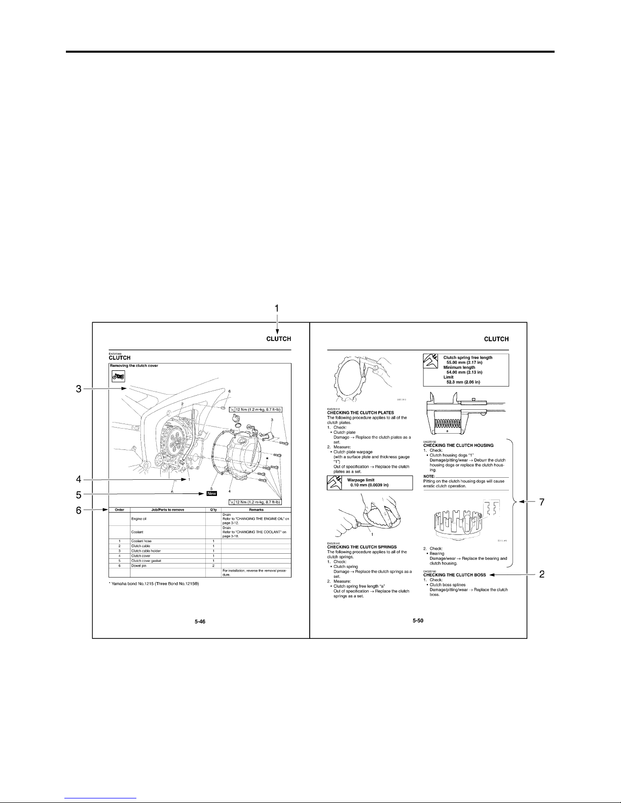
HOW TO USE THIS MANUAL
This manual is intended as a handy, easy-to-read reference book for the mechanic. Comprehensive
explanations of all installation, removal, disassembly, assembly, repair and check procedures are
laid out with the individual steps in sequential order.
• The manual is divided into chapters and each chapter is divided into sections. The current section
title is shown at the top of each page “1”.
• Sub-section titles appear in smaller print than the section title “2”.
• To help identify parts and clarify procedure steps, there are exploded diagrams at the start of each
removal and disassembly section “3”.
• Numbers are given in the order of the jobs in the exploded diagram. A number indicates a disassembly step “4”.
• Symbols indicate parts to be lubricated or replaced “5”.
Refer to “SYMBOLS”.
• A job instruction chart accompanies the exploded diagram, providing the order of jobs, names of
parts, notes in jobs, etc “6”.
• Jobs requiring more information (such as special tools and technical data) are described sequentially “7”.
EAS20100
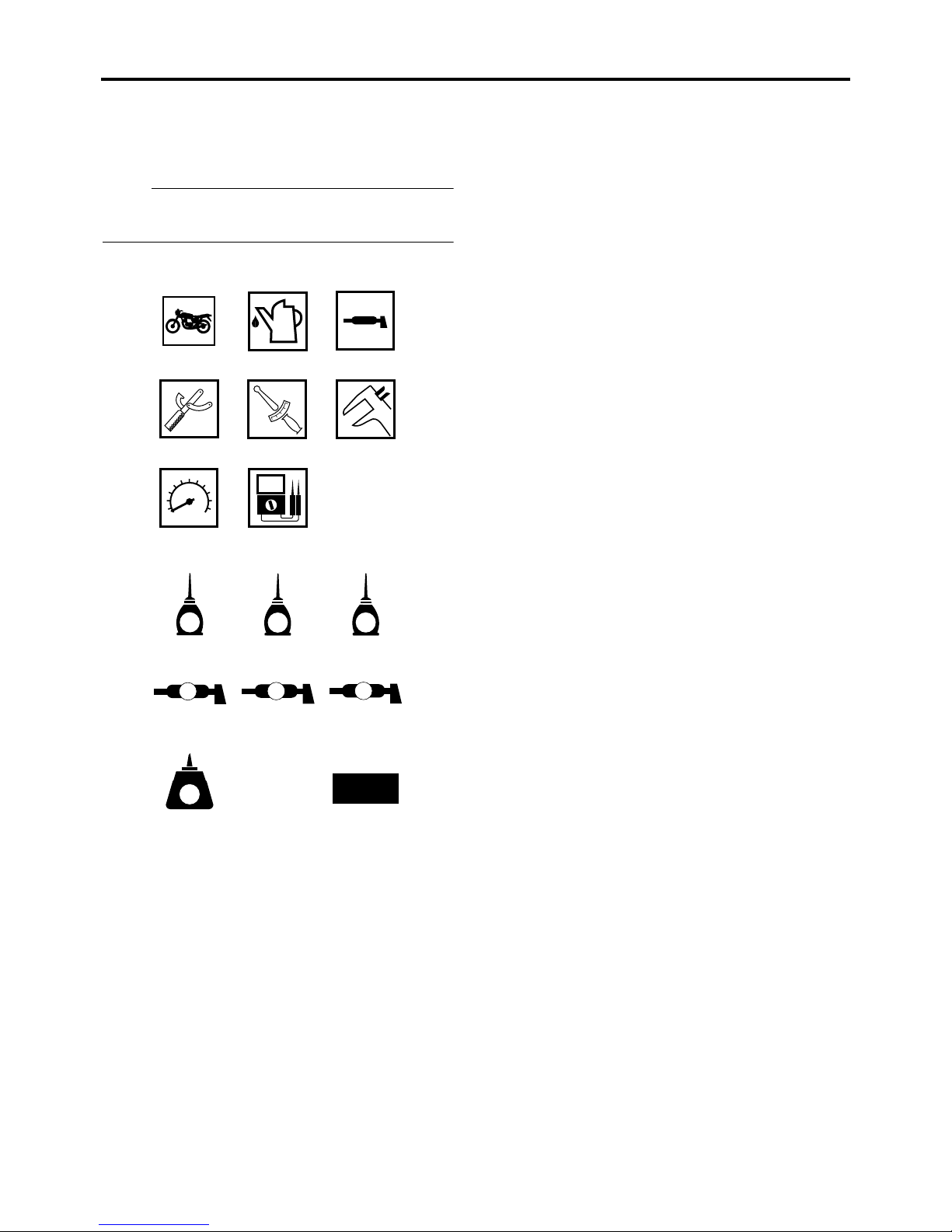
SYMBOLS
The following symbols are used in this manual
for easier understanding.
NOTE:
The following symbols are not relevant to every
vehicle.
123
456
T
.
R
.
78
16.Replace the part
91011
E
G
12 13 14
B
LS
15 16
LT
1. Serviceable with engine mounted
2. Filling fluid
3. Lubricant
4. Special tool
5. Tightening torque
6. Wear limit, clearance
7. Engine speed
8. Electrical data
9. Engine oil
10.Gear oil
11.Molybdenum-disulfide oil
12.Wheel-bearing grease
13.Lithium-soap-based grease
14.Molybdenum-disulfide grease
15.Apply locking agent (LOCTITE®)
New
M
M

EAS20110
TABLE OF CONTENTS
GENERAL INFORMATION
SPECIFICATIONS
PERIODIC CHECKS AND ADJUSTMENTS
CHASSIS
ENGINE
1
2
3
4
5
COOLING SYSTEM
FUEL SYSTEM
ELECTRICAL SYSTEM
TROUBLESHOOTING
6
7
8
9


GENERAL INFORMATION
IDENTIFICATION ..........................................................................................1-1
VEHICLE IDENTIFICATION NUMBER...................................................1-1
MODEL LABEL.......................................................................................1-1
FEATURES ...................................................................................................1-2
OUTLINE OF FI SYSTEM ......................................................................1-2
FI SYSTEM.............................................................................................1-3
INSTRUMENT FUNCTIONS ..................................................................1-4
IMPORTANT INFORMATION .......................................................................1-7
PREPARATION FOR REMOVAL AND DISASSEMBLY .......................... 1-7
REPLACEMENT PARTS.........................................................................1-7
GASKETS, OIL SEALS AND O-RINGS..................................................1-7
LOCK WASHERS/PLATES AND COTTER PINS ...................................1-7
BEARINGS AND OIL SEALS ................................................................. 1-8
CIRCLIPS ...............................................................................................1-8
CHECKING THE CONNECTIONS ...............................................................1-9
1
SPECIAL TOOLS........................................................................................1-10
EAS20130
IDENTIFICATION
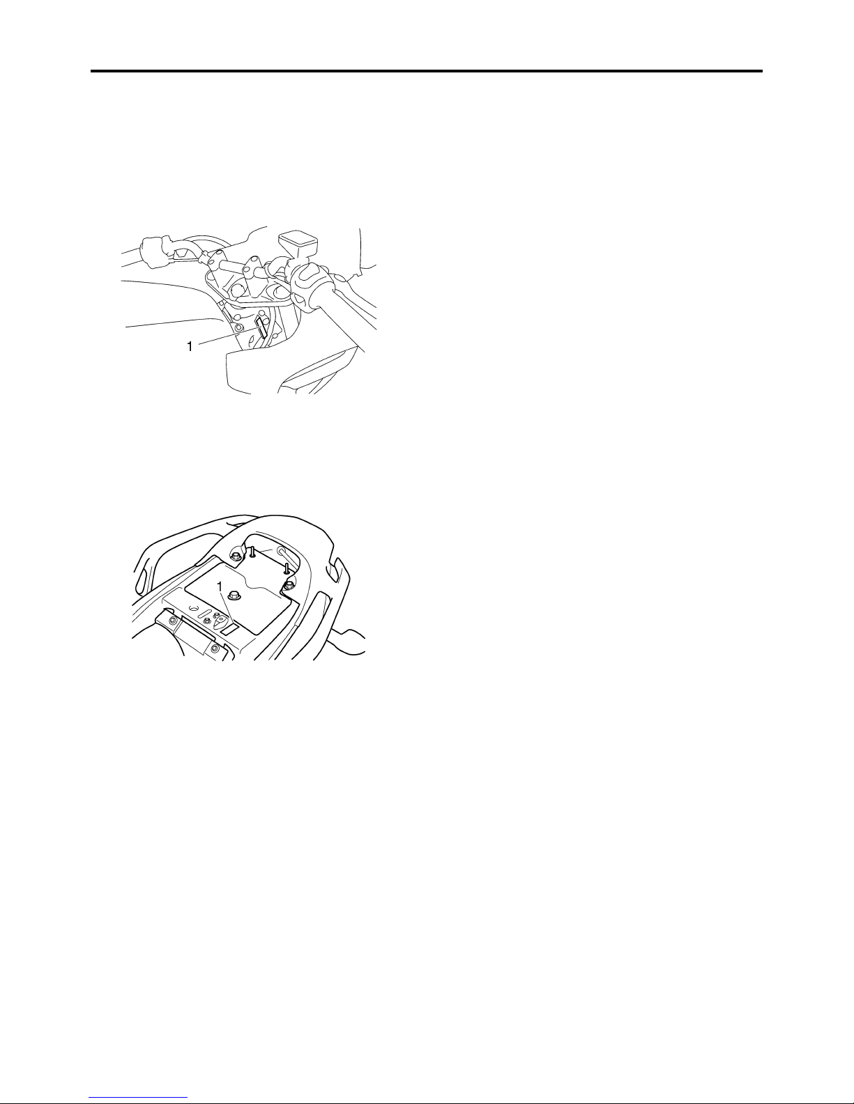
EAS20140
VEHICLE IDENTIFICATION NUMBER
The vehicle identification number “1” is
stamped into the right side of the steering
head pipe.
EAS20150
MODEL LABEL
The model label “1” is affixed to the frame. This
information will be needed to order spare
parts.
IDENTIFICATION
1-1
FEATURES
EAS20170
FEATURES
EAS4S81003
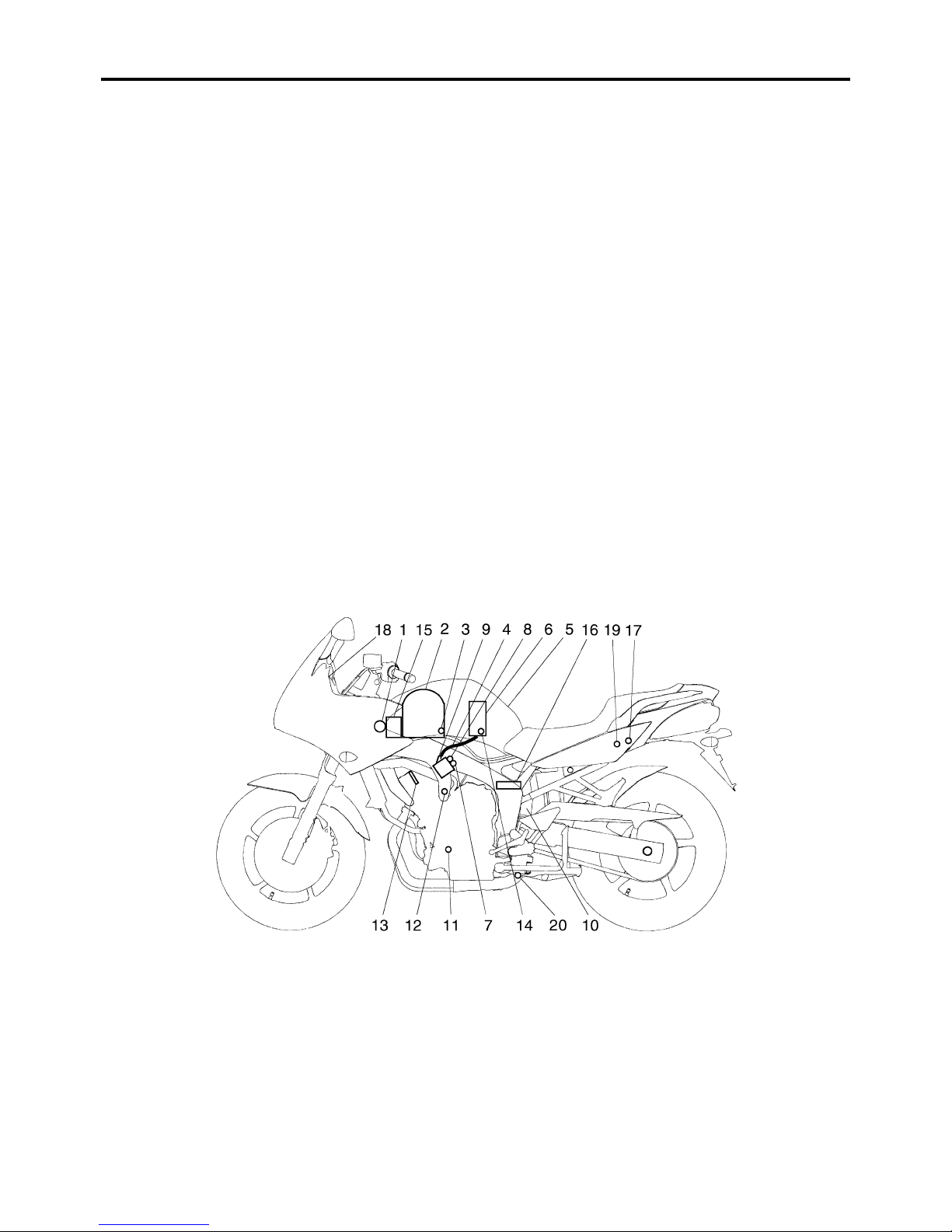
OUTLINE OF FI SYSTEM
The main function of a fuel supply system is to provide fuel to the combustion chamber at the optimum air-fuel ratio in accordance with the engine operating conditions and the atmospheric temperature.
In the conventional carburetor system, the air-fuel ratio of the mixture that is supplied to the combustion chamber is created by the volume of the intake air and the fuel that is metered by the jet used in
the respective carburetor.
Despite the same volume of intake air, the fuel volume requirement varies by the engine operating
conditions, such as acceleration, deceleration, or operating under a heavy load. Carburetors that
meter the fuel through the use of jets have been provided with various auxiliary devices, so that an
optimum air-fuel ratio can be achieved to accommodate the constant changes in the operating conditions of the engine.
As the requirements for the engine to deliver more performance and cleaner exhaust gases
increase, it becomes necessary to control the air-fuel ratio in a more precise and finely tuned manner. To accommodate this need, this model has adopted an electronically controlled fuel injection
(FI) system, in place of the conventional carburetor system. This system can achieve an optimum
air-fuel ratio required by the engine at all times by using a microprocessor that regulates the fuel
injection volume according to the engine operating conditions detected by various sensors.
The adoption of the FI system has resulted in a highly precise fuel supply, improved engine
response, better fuel economy, and reduced exhaust emissions. Furthermore, the air induction system (AI system) has been placed under computer control together with the FI system in order to
realize cleaner exhaust gases.
1. Ignition coil
2. Air filter case
3. Intake air temperature sensor
4. Fuel delivery hose
5. Fuel tank
6. Fuel pump
7. Intake air pressure sensor
8. Throttle position sensor
9. Fuel injector
10.Catalytic converter
11.Crankshaft position sensor
1-2
12.Coolant temperature sensor
13.Spark plug
14.Pressure regulator
15.Battery
16.ECU
17.Fuel injection system relay
18.Engine trouble warning light
19.Lean angle sensor
20.O
sensor
2
FEATURES
EAS4S81004
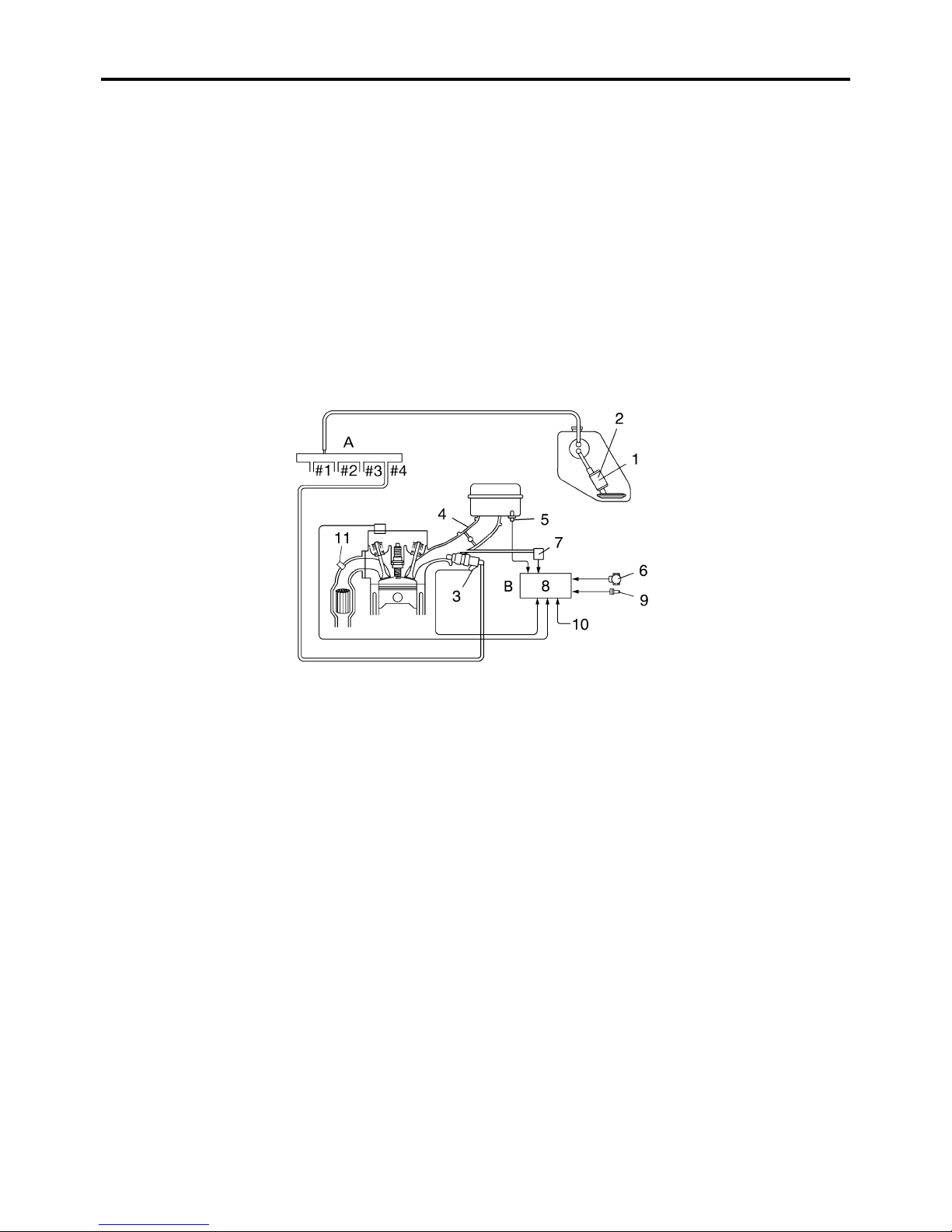
FI SYSTEM
The fuel pump delivers fuel to the injector via the fuel filter. The pressure regulator maintains the fuel
2
pressure that is applied to the injector at only 250 kPa (2.5 kg/cm
ing signal from the ECU energizes the injector, the fuel passage opens, causing the fuel to be
injected into the intake manifold only during the time the passage remains open. Therefore, the
longer the length of time the injector is energized (injection duration), the greater the volume of fuel
that is supplied. Conversely, the shorter the length of time the injector is energized (injection duration), the lesser the volume of fuel that is supplied.
The injection duration and the injection timing are controlled by the ECU. Signals that are input from
the throttle position sensor, crankshaft position sensor, intake air pressure sensor, intake temperature sensor, coolant temperature sensor and O
sensor enable the ECU to determine the injection
2
duration. The injection timing is determined through the signals from the crankshaft position sensor.
As a result, the volume of fuel that is required by the engine can be supplied at all times in accordance with the driving conditions.
). Accordingly, when the energiz-
1. Fuel pump
2. Pressure regulator
3. Fuel injector
4. Throttle body
5. Intake air temperature sensor
6. Throttle position sensor
7. Intake air pressure sensor
8. ECU
9. Coolant temperature sensor
10.Crankshaft position sensor
11.O
sensor
2
A. Fuel system
B. Control system
1-3
FEATURES
EAS4S81005
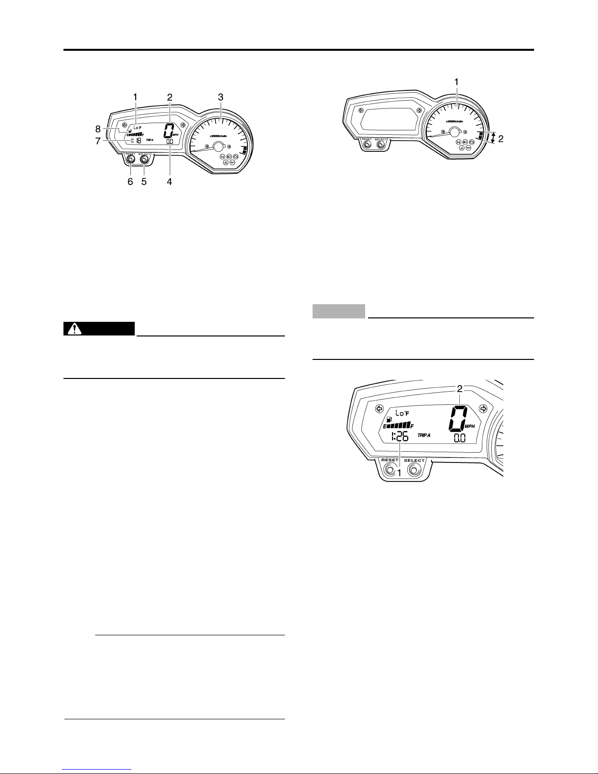
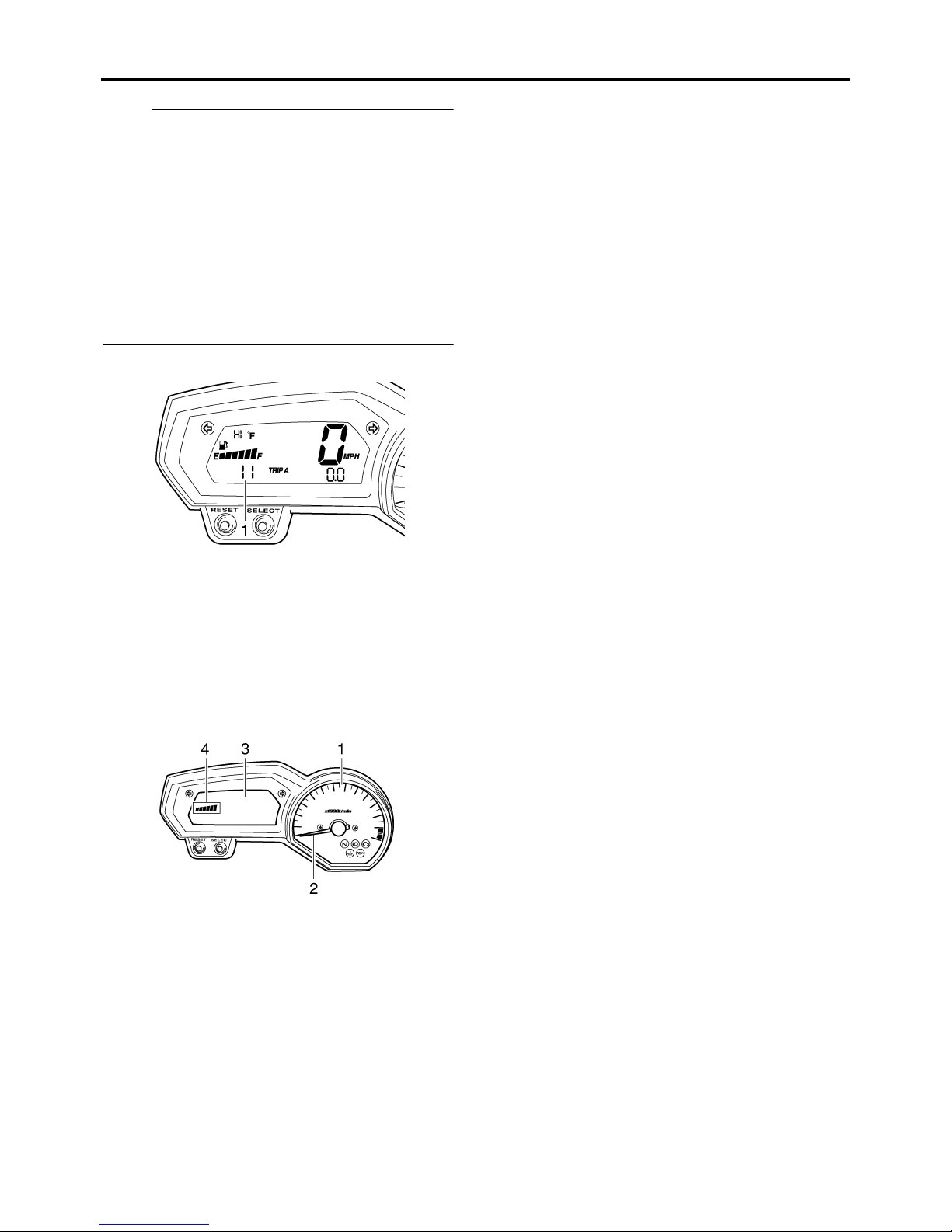
INSTRUMENT FUNCTIONS
1. Coolant temperature display/air intake temperature display
2. Speedometer
3. Tachometer
4. Odometer/tripmeter/fuel reserve tripmeter
5. “SELECT” button
6. “RESET” button
7. Clock
8. Fuel meter
EWA4S81002
WARNING
Be sure to stop the vehicle before making
any setting changes to the multi-function
meter unit.
Tachometer
1. Tachometer
2. Tachometer red zone.
The electric tachometer allows the rider to
monitor the engine speed and keep it within
the ideal power range.
When the key is turned to “ON”, the tachometer needle will sweep once across the r/min
range and then return to zero r/min in order to
test the electrical circuit.
ECA4S81004
CAUTION:
Do not operate the engine in the tachometer red zone.
Red zone: 14000 r/min and above
Clock mode
The multi-function meter unit is equipped with
the following:
• a speedometer (which shows the riding
speed)
• a tachometer (which shows engine speed)
• an odometer (which shows the total distance
traveled)
• two tripmeters (which show the distance traveled since they were last set to zero)
• a fuel reserve tripmeter (which shows the
distance traveled since the left segment of
the fuel meter started flashing)
•a clock
• a fuel meter
• a coolant temperature display
• an air intake temperature displaya self-diagnosis device
• an LCD and tachometer brightness control
mode
NOTE:
• Be sure to turn the key to “ON” before using
the “SELECT” and “RESET” buttons.
• To switch the speedometer and odometer/
tripmeter displays between kilometers and
miles, press the “SELECT” button for at least
one second.
1. Clock
2. Speedometer
The clock is displayed when the key is turned
to “ON”. In addition, the clock can be displayed
for 10 seconds by pushing the “SELECT” button when the main switch is in the “OFF” or
“LOCK” position.
To set the clock
1 Turn the key to “ON”.
2. Push the “SELECT” button and “RESET”
button together for at least two seconds.
3. When the hour digits start flashing, push
the “RESET” button to set the hours.
4. Push the “SELECT” button, and the minute
digits will start flashing.
5. Push the “RESET” button to set the minutes.
6. Push the “SELECT” button and then
release it to start the clock.
1-4
FEATURES
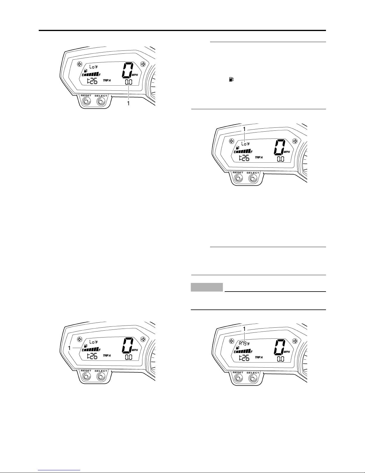
Odometer and tripmeter modes
1. Odometer/tripmeter/fuel reserve tripmeter
Push the “SELECT” button to switch the display between the odometer mode “ODO” and
the tripmeter modes “TRIP A” and “TRIP B” in
the following order:
“TRIP A” → “TRIP B” → “ODO” → “TRIP A”
When the fuel amount in the fuel tank
decreases to 3.4 L (0.90 US gal) (0.75
Imp.gal), the left segment of the fuel meter will
start flashing, and the odometer display will
automatically change to the fuel reserve tripmeter mode “F TRIP” and start counting the
distance traveled from that point. In that case,
push the “SELECT” button to switch the display between the various tripmeter and odometer modes in the following order:
“F-TRIP” → “TRIP A” → “TRIP B” → “ODO” →
“F-TRIP”
To reset a tripmeter, select it by pushing the
“SELECT” button, and then push the “RESET”
button for at least one second. If you do not
reset the fuel reserve tripmeter manually, it will
reset itself automatically and the display will
return to the prior mode after refueling and
traveling 5 km (3 mi).
Fuel meter
NOTE:
This fuel meter is equipped with a self-diagnosis system. If the electrical circuit is defective,
the following cycle will be repeated until the
malfunction is corrected: “E” (Empty), “F” (Full)
and symbol “ ” will flash eight times, then go
off for approximately 3 seconds. If this occurs,
have a Yamaha dealer check the electrical circuit.
Coolant temperature mode
1. Coolant temperature display
The coolant temperature display indicates the
temperature of the coolant.
Push the “RESET” button to switch the coolant
temperature display to the air intake temperature display.
NOTE:
When the coolant temperature display is
selected, “C” is displayed for one second, and
then the coolant temperature is displayed.
ECA4S81009
CAUTION:
Do not operate the engine if it is overheated.
Air intake temperature mode
1. Fuel meter
The fuel meter indicates the amount of fuel in
the fuel tank. The display segments of the fuel
meter disappear towards “E” (Empty) as the
fuel level decreases. When only one segment
is left near “E”, refuel as soon as possible.
1. Air intake temperature display
The air intake temperature display indicates
the temperature of the air drawn into the air filter case. Push the “RESET” button to switch
the coolant temperature display to the air
intake temperature display.
1-5
FEATURES
NOTE:
• Even if the air intake temperature is set to be
displayed, the coolant temperature warning
light comes on when the engine overheats.
• When the key is turned to “ON”, the coolant
temperature is automatically displayed, even
if the air intake temperature was displayed
prior to turning the key to “OFF”.
• When the air intake temperature display is
selected, “A” is displayed for one second,
and then the air intake temperature is displayed.
Self-diagnosis device
4. Push the “RESET” button to select the
desired brightness level.
5. Push the “SELECT” button to confirm the
selected brightness level. The display will
return to the odometer or tripmeter mode.
1. Error code display
This model is equipped with a self-diagnosis
device for various electrical circuits.
If any of those circuits are defective, the engine
trouble warning light will come on, and then the
display will indicate a two-digit error code (e.g.,
11, 12, 13).
LCD and tachometer brightness control mode
1. Tachometer panel
2. Tachometer needle
3. LCD
4. Brightness level
This function allows you to adjust the brightness of the LCD and the tachometer panel and
needle to suit the outside lighting conditions.
To set the brightness
1. Turn the key to “OFF”.
2. Push and hold the “SELECT” button.
3. Turn the key to “ON”, and then release the
“SELECT” button after five seconds.
1-6
EAS20180
IMPORTANT INFORMATION
EAS20190
PREPARATION FOR REMOVAL AND DISASSEMBLY
1. Before removal and disassembly, remove
all dirt, mud, dust and foreign material.
2. Use only the proper tools and cleaning
equipment.
Refer to "SPECIAL TOOLS" on page 1-10.
3. When disassembling, always keep mated
parts together. This includes gears, cylinders, pistons and other parts that have
been “mated” through normal wear. Mated
parts must always be reused or replaced
as an assembly.
IMPORTANT INFORMATION
EAS20210
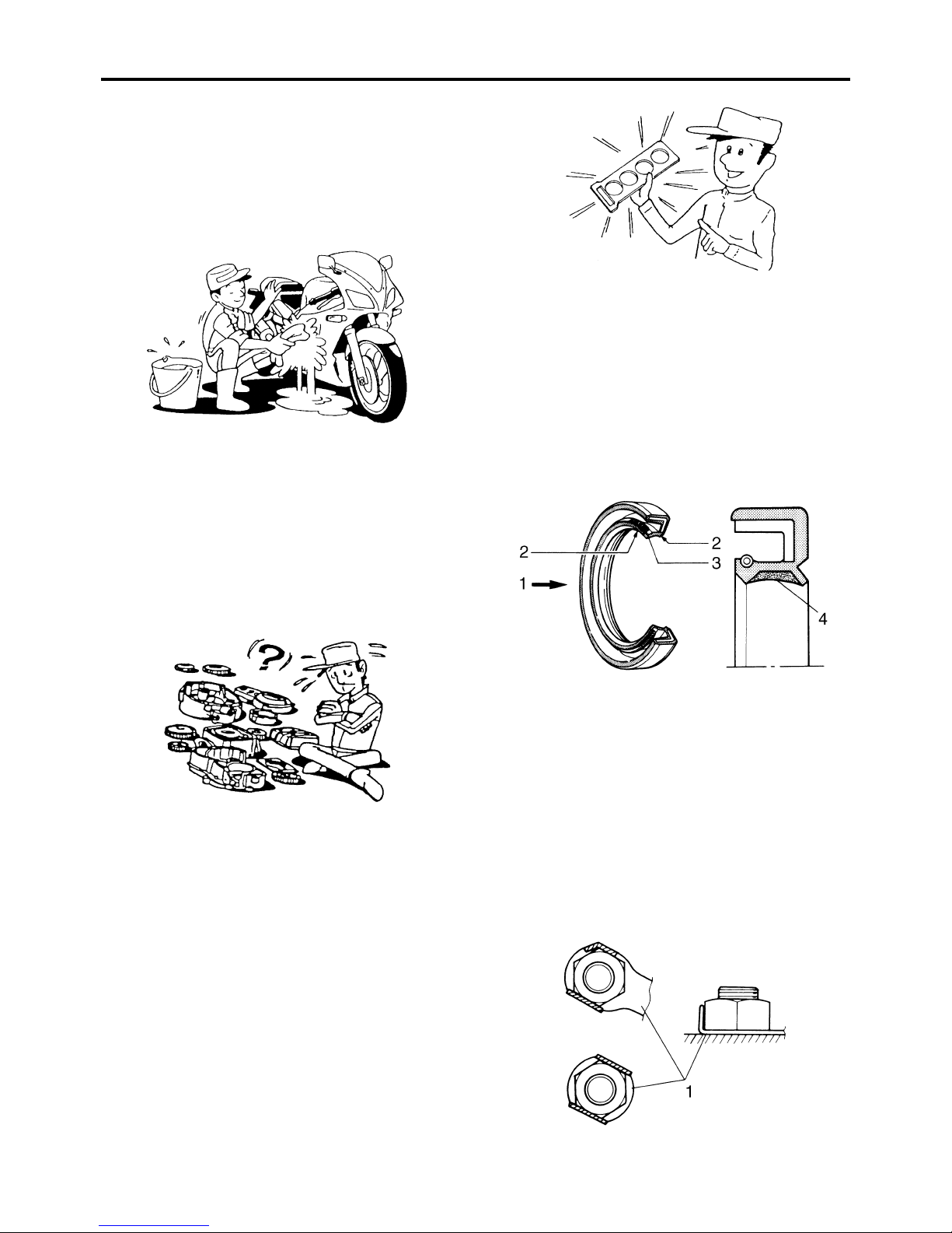
GASKETS, OIL SEALS AND O-RINGS
1. When overhauling the engine, replace all
gaskets, seals and O-rings. All gasket surfaces, oil seal lips and O-rings must be
cleaned.
2. During reassembly, properly oil all mating
parts and bearings and lubricate the oil
seal lips with grease.
4. During disassembly, clean all of the parts
and place them in trays in the order of disassembly. This will speed up assembly and
allow for the correct installation of all parts.
5. Keep all parts away from any source of fire.
EAS20200
REPLACEMENT PARTS
Use only genuine Yamaha parts for all replacements. Use oil and grease recommended by
Yamaha for all lubrication jobs. Other brands
may be similar in function and appearance, but
inferior in quality.
1. Oil
2. Lip
3. Spring
4. Grease
EAS20220
LOCK WASHERS/PLATES AND COTTER
PINS
After removal, replace all lock washers/plates
“1” and cotter pins. After the bolt or nut has
been tightened to specification, bend the lock
tabs along a flat of the bolt or nut.
1-7
EAS20230
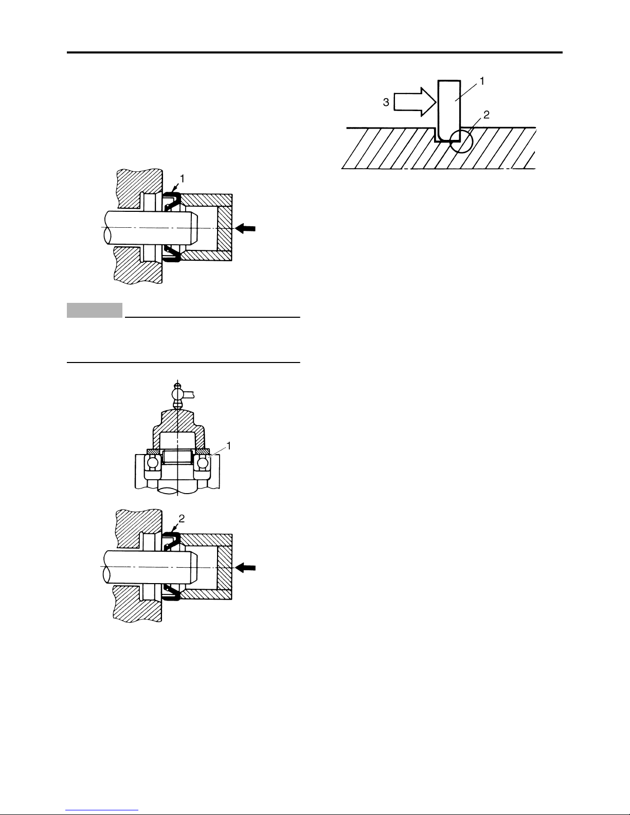
BEARINGS AND OIL SEALS
Install bearings and oil seals so that the manufacturer’s marks or numbers are visible. When
installing oil seals “1”, lubricate the oil seal lips
with a light coat of lithium-soap-based grease.
Oil bearings liberally when installing, if appropriate.
ECA13300
CAUTION:
Do not spin the bearing with compressed
air because this will damage the bearing
surfaces.
IMPORTANT INFORMATION
EAS20240
CIRCLIPS
Before reassembly, check all circlips carefully
and replace damaged or distorted circlips.
Always replace piston pin clips after one use.
When installing a circlip “1”, make sure the
sharp-edged corner “2” is positioned opposite
the thrust “3” that the circlip receives.
1-8
EAS20250
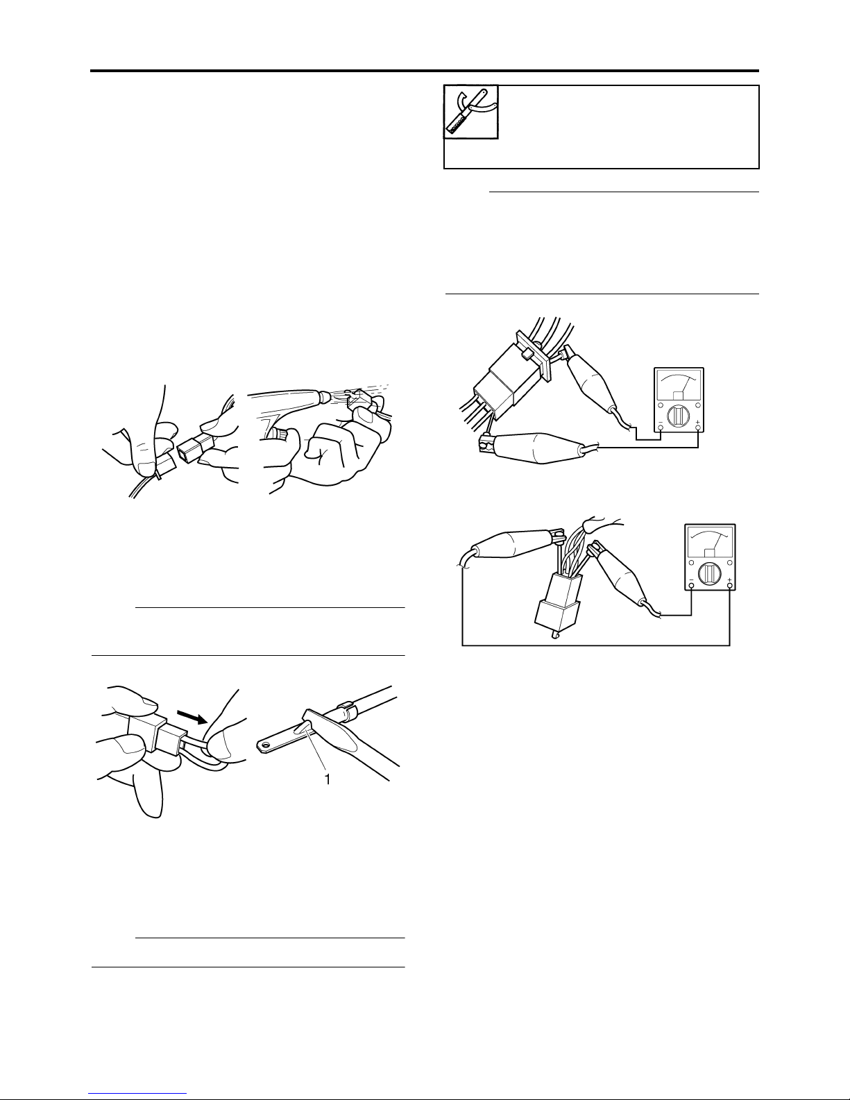
CHECKING THE CONNECTIONS
Check the leads, couplers, and connectors for
stains, rust, moisture, etc.
1. Disconnect:
• Lead
• Coupler
• Connector
2. Check:
• Lead
• Coupler
• Connector
Moisture → Dry with an air blower.
Rust/stains → Connect and disconnect
several times.
CHECKING THE CONNECTIONS
Pocket tester
90890-03112
Analog pocket tester
YU-03112-C
NOTE:
• If there is no continuity, clean the terminals.
• When checking the wire harness, perform
steps (1) to (3).
• As a quick remedy, use a contact revitalizer
available at most part stores.
3. Check:
• All connections
Loose connection → Connect properly.
NOTE:
If the pin “1” on the terminal is flattened, bend
it up.
4. Connect:
• Lead
• Coupler
• Connector
NOTE:
Make sure all connections are tight.
5. Check:
•Continuity
(with the pocket tester)
1-9
SPECIAL TOOLS
EAS20260
SPECIAL TOOLS
The following special tools are necessary for complete and accurate tune-up and assembly. Use
only the appropriate special tools as this will help prevent damage caused by the use of inappropriate tools or improvised techniques. Special tools, part numbers or both may differ depending on the
country.
When placing an order, refer to the list provided below to avoid any mistakes.
NOTE:
• For U.S.A. and Canada, use part number starting with “YM-”, “YU-”, or “ACC-”.
• For others, use part number starting with “90890-”.
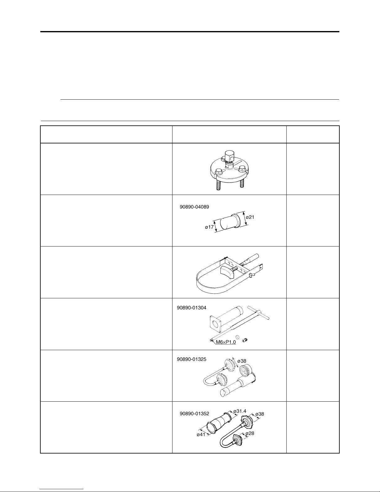
Tool name/Tool No. Illustration
Flywheel puller
90890-01362
Heavy duty puller
YU-33270-B
Flywheel puller attachment
90890-04089
Crankshaft protector
YM-33282
Sheave holder
90890-01701
Primary clutch holder
YS-01880-A
Piston pin puller set
90890-01304
Piston pin puller
YU-01304
Reference
pages
5-30
5-30
5-30, 5-31, 532, 5-34
5-62
Radiator cap tester
90890-01325
Radiator pressure tester
YU-24460-01
Radiator cap tester adapter
90890-01352
Radiator pressure tester adapter
YU-33984
6-3
6-3
1-10
SPECIAL TOOLS
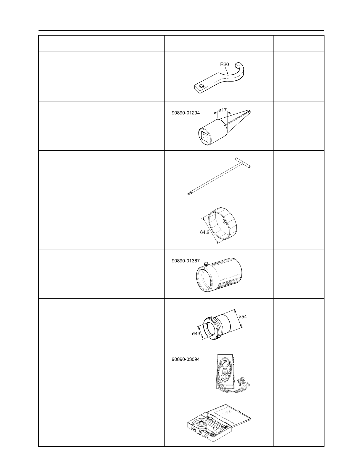
Tool name/Tool No. Illustration
Steering nut wrench
90890-01403
Spanner wrench
YU-33975
Damper rod holder
90890-01294
Damping rod holder set
YM-01300
T-handle
90890-01326
YM-01326
Oil filter wrench
90890-01426
YU-38411
Reference
pages
3-26, 4-53
4-45, 4-47
4-45, 4-47
3-13
Fork seal driver weight
90890-01367
Replacement hammer
YM-A9409-7
Fork seal driver attachment (ø43)
90890-01374
Replacement 43 mm
YM-A5142-3
Vacuum gauge
90890-03094
Carburetor synchronizer
YU-44456
Compression gauge
90890-03081
Engine compression tester
YU-33223
4-47, 4-48
4-47
3-7
3-11
1-11
SPECIAL TOOLS
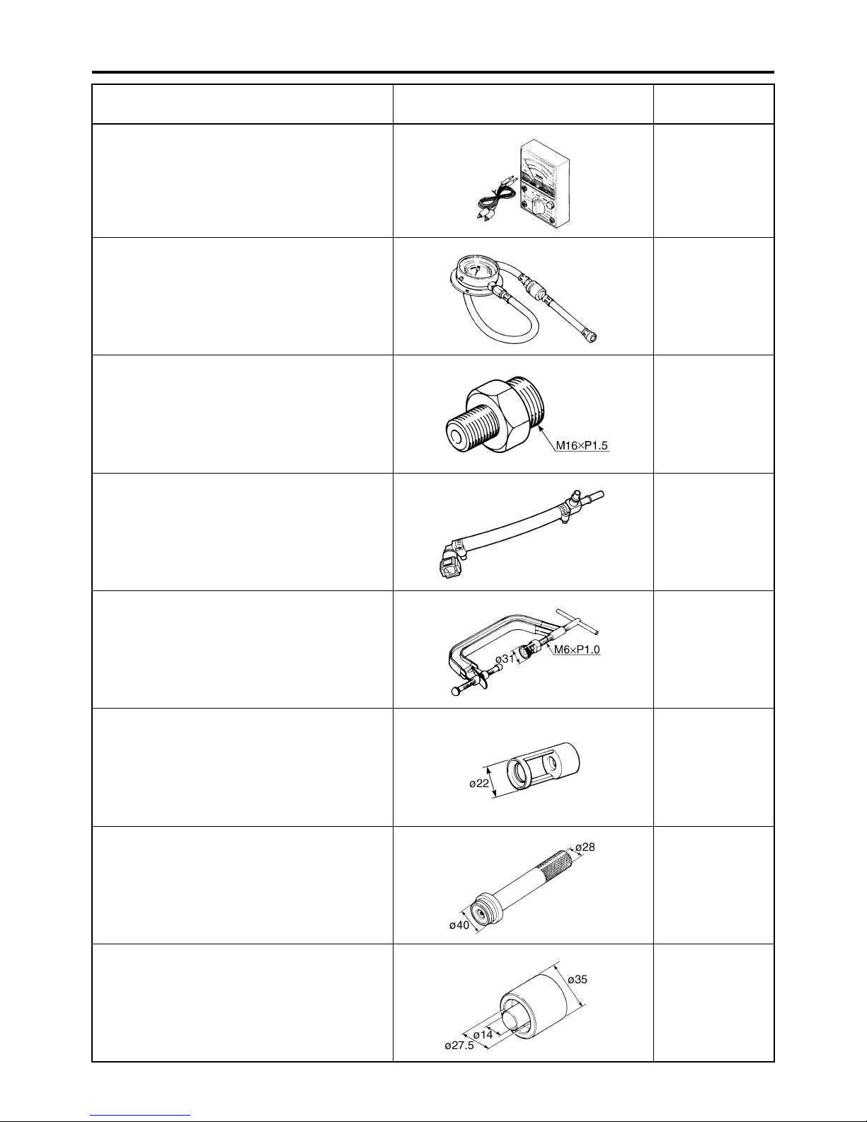
Tool name/Tool No. Illustration
Pocket tester
90890-03112
Analog pocket tester
YU-03112-C
Pressure gauge
90890-03153
YU-03153
Oil pressure adapter H
90890-03139
Fuel pressure adapter
90890-03176
YM-03176
Reference
pages
1-9, 5-38, 8-65,
8-66, 8-67, 8-71,
8-72, 8-73, 8-74,
8-75, 8-76, 8-77,
8-78, 8-79, 8-80,
8-81, 8-82
3-14, 7-6
3-14
7-6
Valve spring compressor
90890-04019
YM-04019
Valve spring compressor attachment
90890-04108
Valve spring compressor adapter 22 mm
YM-04108
Middle driven shaft bearing driver
90890-04058
Bearing driver 40 mm
YM-04058
Mechanical seal installer
90890-04078
Water pump seal installer
YM-33221-A
5-21, 5-27
5-21, 5-27
6-12
6-12
1-12
SPECIAL TOOLS
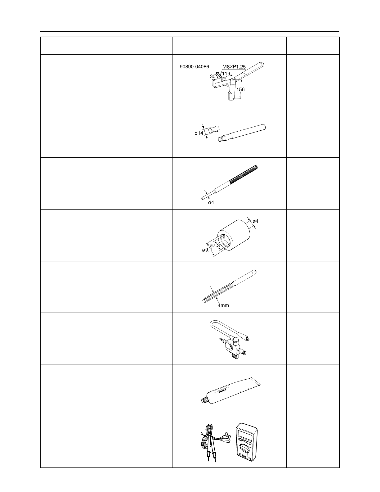
Tool name/Tool No. Illustration
Universal clutch holder
90890-04086
YM-91042
Valve lapper
90890-04101
Valve lapping tool
YM-A8998
Valve guide remover (ø4)
90890-04111
Valve guide remover (4.0 mm)
YM-04111
Valve guide installer (ø4)
90890-04112
Valve guide installer (4.0 mm)
YM-04112
Reference
pages
5-49, 5-51
3-5
5-23
5-23
Valve guide reamer (ø4)
90890-04113
Valve guide reamer (4.0 mm)
YM-04113
Ignition checker
90890-06754
Opama pet-4000 spark checker
YM-34487
Yamaha bond No. 1215
(Three bond No.1215®)
90890-85505
Digital circuit tester
90890-03174
Model 88 Multimeter with tachometer
YU-A1927
5-23
8-74
5-32, 5-35, 558, 6-12
7-7
1-13

SPECIFICATIONS
GENERAL SPECIFICATIONS ......................................................................2-1
ENGINE SPECIFICATIONS..........................................................................2-2
CHASSIS SPECIFICATIONS........................................................................2-9
ELECTRICAL SPECIFICATIONS...............................................................2-12
TIGHTENING TORQUES............................................................................2-15
GENERAL TIGHTENING TORQUE SPECIFICATIONS....................... 2-15
ENGINE TIGHTENING TORQUES ......................................................2-16
CHASSIS TIGHTENING TORQUES ....................................................2-20
LUBRICATION POINTS AND LUBRICANT TYPES ..................................2-22
ENGINE ................................................................................................2-22
CHASSIS ..............................................................................................2-23
2
LUBRICATION SYSTEM CHART AND DIAGRAMS .................................2-25
ENGINE OIL LUBRICATION CHART ...................................................2-25
LUBRICATION DIAGRAMS ..................................................................2-27
COOLING SYSTEM DIAGRAMS ...............................................................2-39
CABLE ROUTING ......................................................................................2-47

GENERAL SPECIFICATIONS
EAS20280
GENERAL SPECIFICATIONS
Model
Model 4S82 (U.S.A.)
Dimensions
Overall length 2095 mm (82.5 in)
Overall width 750 mm (29.5 in)
Overall height 1210 mm (47.6 in)
Seat height 795 mm (31.3 in)
Wheelbase 1440 mm (56.7 in)
Ground clearance 145 mm (5.71 in)
Minimum turning radius 2800 mm (110.2 in)
Weight
With oil and fuel 207.0 kg (456 lb) (FZS6W)
Maximum load 189 kg (417 lb) (FZS6WC)
4S83 (California)
208.0 kg (459 lb) (FZS6WC)
190 kg (419 lb) (FZS6W)
2-1

ENGINE SPECIFICATIONS
EAS20290
ENGINE SPECIFICATIONS
Engine
Engine type Liquid cooled 4-stroke, DOHC
Displacement 600.0 cm³
Cylinder arrangement Forward-inclined parallel 4-cylinder
Bore × stroke 65.5 × 44.5 mm (2.58 × 1.75 in)
Compression ratio 12.20 :1
Standard compression pressure (at sea level) 1550 kPa/400 r/min (220.5 psi/400 r/min) (15.5
kgf/cm²/400 r/min)
Minimum–maximum 1300–1650 kPa (184.9–234.7 psi) (13.0–16.5
kgf/cm²)
Starting system Electric starter
Fuel
Recommended fuel Unleaded gasoline only
Fuel tank capacity 19.4 L (5.13 US gal) (4.27 Imp.gal)
Fuel reserve amount 3.6 L (0.95 US gal) (0.79 Imp.gal)
Engine oil
Lubrication system Wet sump
Type YAMALUBE 4, SAE10W30 or SAE 20W40
Recommended engine oil grade API service SG type or higher, JASO standard
MA
Engine oil quantity
Total amount 3.40 L (3.59 US qt) (2.99 Imp.qt)
Without oil filter cartridge replacement 2.50 L (2.64 US qt) (2.20 Imp.qt)
With oil filter cartridge replacement 2.80 L (2.96 US qt) (2.46 Imp.qt)
Oil pressure 240 kPa at 6,600 r/min
(2.4 kg/cm² at 6,600 r/min)
(2.4 bar at 6,600 r/min)
(34.1 psi at 6,600 r/min)
Oil filter
Oil filter type Formed
Oil pump
Oil pump type Trochoid
Inner-rotor-to-outer-rotor-tip clearance 0.030–0.090 mm (0.0012–0.0035 in)
Limit 0.15 mm (0.0059 in)
Outer-rotor-to-oil-pump-housing clearance 0.030–0.080 mm (0.0012–0.0032 in)
Limit 0.150 mm (0.0059 in)
Bypass valve opening pressure 80.0–120.0 kPa (11.6–17.4 psi) (0.80–1.20
kgf/cm²)
Relief valve operating pressure 450.0–550.0 kPa (65.3–79.8 psi) (4.50–5.50
kgf/cm²)
Pressure check location Main gallery
Cooling system
Radiator capacity (including all routes) 2.00 L (2.11 US qt) (1.76 Imp.qt)
Radiator capacity 0.60 L (0.63 US qt) (0.53 Imp.qt)
Coolant reservoir capacity (up to the maximum
level mark) 0.25 L (0.26 US qt) (0.22 Imp.qt)
Radiator cap opening pressure 93–123 kPa (13.2–17.5 psi) (0.93–1.23 kgf/
cm²)
Radiator core
Width 300.0 mm (11.81 in)
Height 188.0 mm (7.40 in)
Depth 24.0 mm (0.94 in)
2-2
ENGINE SPECIFICATIONS
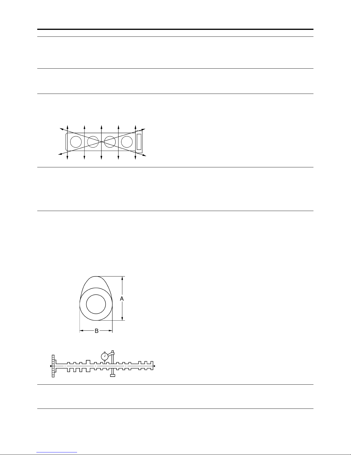
Water pump
Water pump type Single suction centrifugal pump
Reduction ratio 86/44 × 31/31 (1.955)
Max. impeller shaft tilt 0.15 mm (0.006 in)
Spark plug (s)
Manufacturer/model NGK/CR9EK
Spark plug gap 0.6–0.7 mm (0.024–0.028 in)
Cylinder head
Volume 10.33–10.93 cm³ (0.63–0.67 cu.in)
Warpage limit 0.05 mm (0.0020 in)
Camshaft
Drive system Chain drive (right)
Camshaft cap inside diameter 23.008–23.029 mm (0.9058–0.9067 in)
Camshaft journal diameter 22.967–22.980 mm (0.9042–0.9047 in)
Camshaft-journal-to-camshaft-cap clearance 0.028–0.062 mm (0.0011–0.0024 in)
Limit 0.080 mm (0.0032 in)
Camshaft lobe dimensions
Intake A 32.450–32.550 mm (1.2776–1.2815 in)
Limit 32.400 mm (1.2756 in)
Intake B 24.950–25.050 mm (0.9823–0.9862 in)
Limit 24.900 mm (0.9803 in)
Exhaust A 32.450–32.550 mm (1.2776–1.2815 in)
Limit 32.400 mm (1.2756 in)
Exhaust B 24.950–25.050 mm (0.9823–0.9862 in)
Limit 24.900 mm (0.9803 in)
Camshaft runout limit 0.060 mm (0.0024 in)
Timing chain
Model/number of links 92RH2015/120
Tensioning system Automatic
Valve clearance (cold)
Intake 0.13–0.20 mm (0.0051–0.0079 in)
Exhaust 0.23–0.30 mm (0.0091–0.0118 in)
2-3
ENGINE SPECIFICATIONS
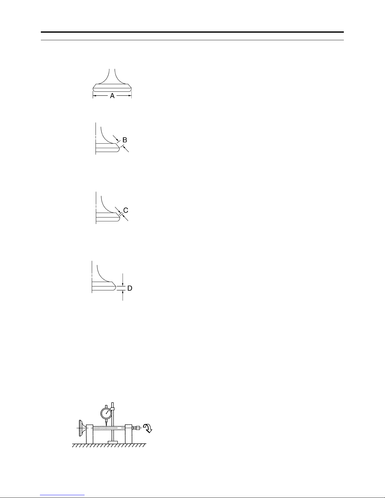
Valve dimensions
Valve head diameter A (intake) 24.90–25.10 mm (0.9803–0.9882 in)
Valve head diameter A (exhaust) 21.90–22.10 mm (0.8622–0.8701 in)
Valve face width B (intake) 1.140–1.980 mm (0.0449–0.0780 in)
Valve face width B (exhaust) 1.140–1.980 mm (0.0449–0.0780 in)
Valve seat width C (intake) 0.90–1.10 mm (0.0354–0.0433 in)
Limit 1.6 mm (0.06 in)
Valve seat width C (exhaust) 0.90–1.10 mm (0.0354–0.0433 in)
Limit 1.6 mm (0.06 in)
Valve margin thickness D (intake) 0.60–0.80 mm (0.0236–0.0315 in)
Limit 0.5 mm (0.02 in)
Valve margin thickness D (exhaust) 0.60–0.80 mm (0.0236–0.0315 in)
Limit 0.5 mm (0.02 in)
Valve stem diameter (intake) 3.975–3.990 mm (0.1565–0.1571 in)
Limit 3.950 mm (0.1555 in)
Valve stem diameter (exhaust) 3.960–3.975 mm (0.1559–0.1565 in)
Limit 3.935 mm (0.1549 in)
Valve guide inside diameter (intake) 4.000–4.012 mm (0.1575–0.1580 in)
Limit 4.042 mm (0.1591 in)
Valve guide inside diameter (exhaust) 4.000–4.012 mm (0.1575–0.1580 in)
Limit 4.042 mm (0.1591 in)
Valve-stem-to-valve-guide clearance (intake) 0.010–0.037 mm (0.0004–0.0015 in)
Limit 0.080 mm (0.0032 in)
Valve-stem-to-valve-guide clearance (exhaust) 0.025–0.052 mm (0.0010–0.0020 in)
Limit 0.100 mm (0.0039 in)
Valve stem runout 0.040 mm (0.0016 in)
Cylinder head valve seat width (intake) 0.90–1.10 mm (0.0354–0.0433 in)
Limit 1.6 mm (0.06 in)
Cylinder head valve seat width (exhaust) 0.90–1.10 mm (0.0354–0.0433 in)
2-4
ENGINE SPECIFICATIONS
Limit 1.6 mm (0.06 in)
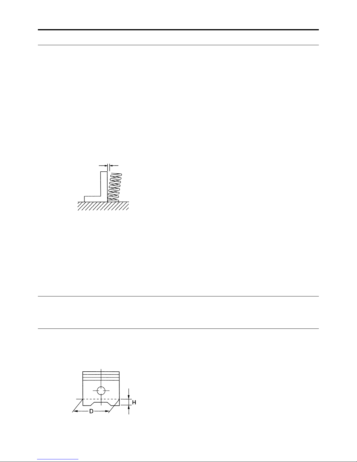
Valve spring
Inner spring
Free length (intake) 37.04 mm (1.46 in)
Limit 35.20 mm (1.39 in)
Free length (exhaust) 41.79 mm (1.65 in)
Limit 39.70 mm (1.56 in)
Installed length (intake) 30.02 mm (1.18 in)
Installed length (exhaust) 36.12 mm (1.42 in)
Spring rate K1 (intake) 10.50 N/mm (59.96 lb/in) (1.07 kgf/mm)
Spring rate K2 (intake) 17.00 N/mm (97.07 lb/in) (1.73 kgf/mm)
Spring rate K1 (exhaust) 30.26 N/mm (172.78 lb/in) (3.09 kgf/mm)
Spring rate K2 (exhaust) 49.53 N/mm (282.82 lb/in) (5.05 kgf/mm)
Installed compression spring force (intake) 69–79 N (15.51–17.76 lbf) (7.04–8.06 kgf)
Installed compression spring force (exhaust) 160–184 N (35.97–41.36 lbf) (16.32–18.76
kgf)
Spring tilt (intake) 2.5 °/1.6 mm (0.06 in)
Spring tilt (exhaust) 2.5 °/1.8 mm (0.07 in)
Winding direction (intake) Counter clockwise
Winding direction (exhaust) Clockwise
Outer spring
Free length (intake) 38.40 mm (1.51 in)
Limit 36.50 mm (1.44 in)
Installed length (intake) 32.52 mm (1.28 in)
Spring rate K1 (intake) 20.80 N/mm (118.77 lb/in) (2.12 kgf/mm)
Spring rate K2 (intake) 33.30 N/mm (190.14 lb/in) (3.40 kgf/mm)
Installed compression spring force (intake) 114–132 N (25.63–29.67 lbf) (11.62–13.46
kgf)
Spring tilt (intake) 2.5 °/1.7 mm (0.07 in)
Winding direction (intake) Clockwise
Cylinder
Bore 65.500–65.510 mm (2.5787–2.5791 in)
Taper limit 0.050 mm (0.0020 in)
Out of round limit 0.050 mm (0.0020 in)
Piston
Piston-to-cylinder clearance 0.010–0.035 mm (0.0004–0.0014 in)
Limit 0.05 mm (0.0020 in)
Diameter D 65.475–65.490 mm (2.5778–2.5783 in)
Height H 4.0 mm (0.16 in)
2-5
ENGINE SPECIFICATIONS
Offset 0.50 mm (0.0197 in)
Offset direction Intake side
Piston pin bore inside diameter 16.002–16.013 mm (0.6300–0.6304 in)
Limit 16.043 mm (0.6316 in)
Piston pin outside diameter 15.991–16.000 mm (0.6296–0.6299 in)
Limit 15.971 mm (0.6288 in)
Piston-pin-to-piston-pin-bore clearance 0.002–0.022 mm (0.0001–0.0009 in)
Limit 0.072 mm (0.0028 in)
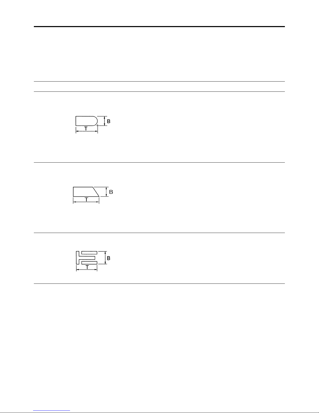
Piston ring
Top ring
Ring type Barrel
Dimensions (B × T) 0.90 × 2.45 mm (0.04 × 0.10 in)
End gap (installed) 0.25–0.35 mm (0.0098–0.0138 in)
Limit 0.60 mm (0.0236 in)
Ring side clearance 0.030–0.065 mm (0.0012–0.0026 in)
Limit 0.115 mm (0.0045 in)
2nd ring
Ring type Taper
Dimensions (B × T) 0.80 × 2.50 mm (0.03 × 0.10 in)
End gap (installed) 0.70–0.80 mm (0.0276–0.0315 in)
Limit 1.15 mm (0.0453 in)
Ring side clearance 0.030–0.065 mm (0.0012–0.0026 in)
Limit 0.125 mm (0.0049 in)
Oil ring
Dimensions (B × T) 1.50 × 2.00 mm (0.06 × 0.08 in)
End gap (installed) 0.10–0.35 mm (0.0039–0.0138 in)
Connecting rod
Oil clearance (using plastigauge®) 0.028–0.052 mm (0.0011–0.0020 in)
Limit 0.08 mm (0.0032 in)
Bearing color code 1.Blue 2.Black 3.Brown 4.Green
2-6
ENGINE SPECIFICATIONS
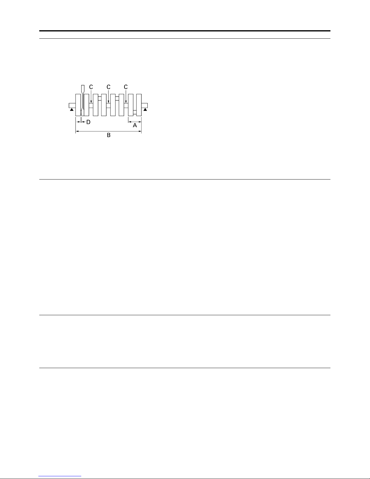
Crankshaft
Width A 51.850–52.550 mm (2.04–2.06 in)
Width B 268.80–270.00 mm (10.58–10.63 in)
Runout limit C 0.030 mm (0.0012 in)
Big end side clearance D 0.160–0.262 mm (0.0063–0.0103 in)
Big end radial clearance 0.028–0.052 mm (0.0011–0.0020 in)
Small end free play 0.32–0.50 mm (0.01–0.02 in)
Journal oil clearance (using plastigauge®) 0.034–0.058 mm (0.0013–0.0023 in)
Limit 0.10 mm (0.0039 in)
Bearing color code 0.White 1.Black 2.Brown 3.Green 4.Yellow
Clutch
Clutch type Wet, multiple-disc
Clutch release method Outer pull, rack and pinion pull
Clutch release method operation Cable operation
Clutch lever free play 10.0–15.0 mm (0.39–0.59 in)
Friction plate thickness 2.92–3.08 mm (0.115–0.121 in)
Wear limit 2.80 mm (0.1102 in)
Plate quantity 6 pcs
Friction plate thickness 2.92–3.08 mm (0.115–0.121 in)
Plate quantity 2 pcs
Clutch plate thickness 1.90–2.10 mm (0.075–0.083 in)
Plate quantity 7 pcs
Warpage limit 0.10 mm (0.0039 in)
Clutch plate thickness 2.20–2.40 mm (0.087–0.094 in)
Plate quantity 1 pcs
Warpage limit 0.10 mm (0.0039 in)
Clutch spring free length 55.00 mm (2.17 in)
Limit 52.30 mm (2.06 in)
Spring quantity 6 pcs
Transmission
Transmission type Constant mesh 6-speed
Primary reduction system Spur gear
Primary reduction ratio 86/44 (1.955)
Secondary reduction system Chain drive
Secondary reduction ratio 46/16 (2.875)
Operation Left foot operation
Gear ratio
1st 37/13 (2.846)
2nd 37/19 (1.947)
3rd 28/18 (1.556)
4th 32/24 (1.333)
5th 25/21 (1.190)
6th 26/24 (1.083)
Main axle runout limit 0.02 mm (0.0008 in)
Drive axle runout limit 0.02 mm (0.0008 in)
2-7
 Loading...