

YAMAHA FT50C PARTS CATALOGUE

FT50C
SERVICE MANUAL
290418
62Y-28197-5A-11

NOTICE
This manual has been prepared by Yamaha primarily for use by Yamaha dealers and their trained
mechanics when performing maintenance procedures and repairs to Yamaha equipment. It has
been written to suit the needs of persons who have a basic understanding of the mechanical and
electrical concepts and procedures inherent in the work, for without such knowledge attempted
repairs or service to the equipment could render it unsafe or unfit for use.
Because Yamaha has a policy of continuously improving its products, models may differ in detail
from the descriptions and illustrations given in this publication. Use only the latest edition of this
manual. Authorized Yamaha dealers are notified periodically of modifications and significant
changes in specifications and procedures, and these are incorporated in successive editions of this
manual.
Important information
Particularly important information is distinguished in this manual by the following notations:
The Safety Alert Symbol means ATTENTION! BECOME ALERT! YOUR SAFETY IS
INVOLVED!
WARNING
Failure to follow WARNING instructions could result in severe injury or death to the machine
operator, a bystander, or a person inspecting or repairing the outboard motor.
CAUTION:
A CAUTION indicates special precautions that must be taken to avoid damage to the outboard motor.
NOTE:
A NOTE provides key information to make procedures easier or clearer.
1
FT50C
SERVICE MANUAL
©2001 by Yamaha Motor Co., Ltd.
1st Edition, June 2001
All rights reserved.
Any reprinting or unauthorized use
without the written permission of
Yamaha Motor Co., Ltd.
is expressly prohibited.
Printed in the Netherlands
Contents
General information
Specifications
Periodic checks and adjustments
Fuel system
Power unit
GEN
INFO
SPEC
CHK
ADJ
FUEL
POWR
1
2
3
4
5
Lower unit
Bracket unit
Electrical systems
Troubleshooting
Index
LOWR
BRKT
–+
ELEC
TRBL
SHTG
6
7
8
9

GEN
INFO
General information
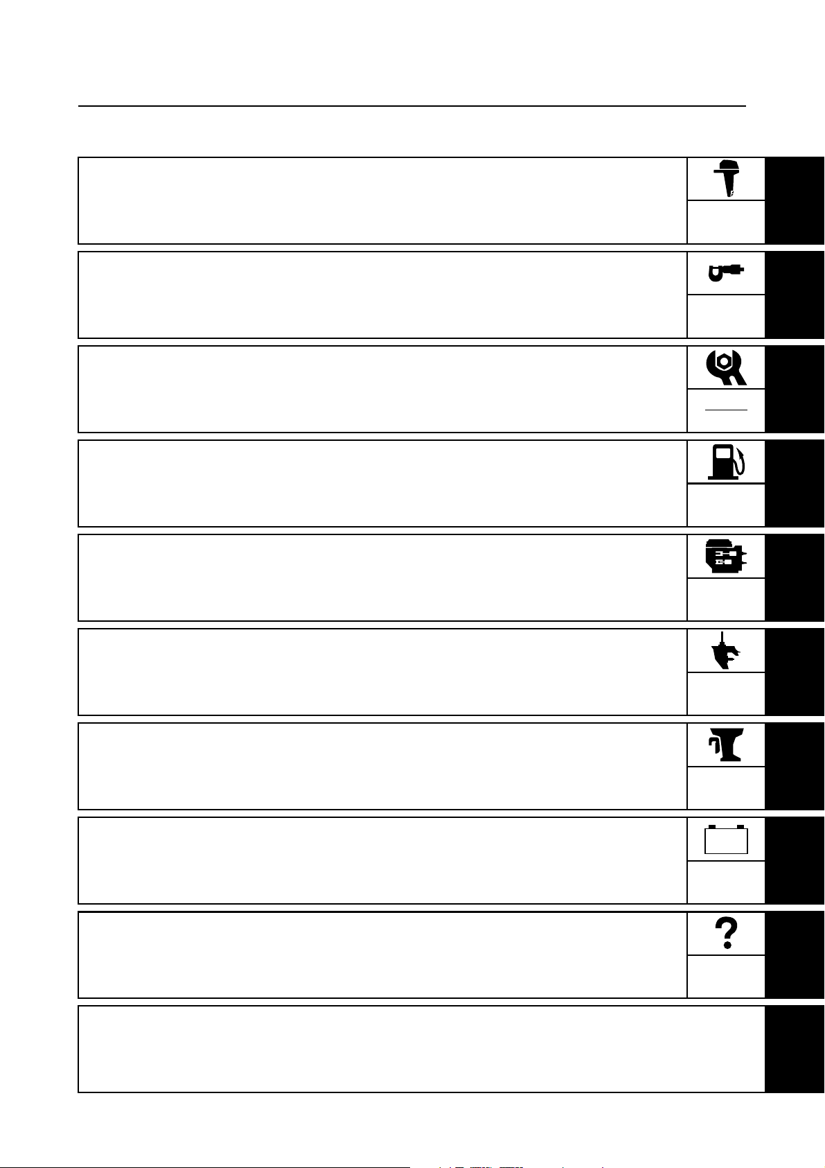
How to use this manual.................................................................................1-1
Manual format............................................................................................1-1
Symbols.....................................................................................................1-2
Safety while working......................................................................................1-3
Fire prevention...........................................................................................1-3
Ventilation..................................................................................................1-3
Self-protection ...........................................................................................1-3
Parts, lubricants, and sealants ..................................................................1-3
Good working practices .............................................................................1-4
Disassembly and assembly .......................................................................1-4
Identification...................................................................................................1-4
Applicable models .....................................................................................1-4
Serial number ............................................................................................1-4
Features and benefits....................................................................................1-5
Use of leaded gasoline ..............................................................................1-5
Newly designed four carburetors............................................................... 1-5
CDI unit with microcomputer .....................................................................1-6
Lower unit ..................................................................................................1-7
Technical tips .................................................................................................1-8
Carburetor .................................................................................................1-8
Acceleration pump...................................................................................1-13
Ignition system.........................................................................................1-15
Ignition timing control...............................................................................1-17
Power trim and tilt....................................................................................1-19
Propeller selection.......................................................................................1-26
Propeller size...........................................................................................1-26
Selection..................................................................................................1-26
62Y5A11

Predelivery checks ......................................................................................1-26
Checking the fuel system ........................................................................1-26
Checking the gear oil...............................................................................1-27
Checking the engine oil ...........................................................................1-27
Checking the battery................................................................................1-27
Checking the outboard motor mounting position..................................... 1-27
Checking the remote control cables ........................................................ 1-27
Checking the steering system .................................................................1-28
Checking the gearshift and throttle operation..........................................1-28
Checking the tilt system...........................................................................1-28
Checking the engine start switch and engine stop switch/
engine shut-off switch ............................................................................1-29
Checking the pilot water outlet ................................................................1-29
Test run ...................................................................................................1-29
Break-in ...................................................................................................1-29
After test run ............................................................................................1-29
1
2
3
4
5
6
7
8
9
62Y5A11
GEN
INFO
General information
How to use this manual
Manual format
The format of this manual has been designed to make service procedures clear and easy to understand. Use the information below as a guide for effective and quality service.
1
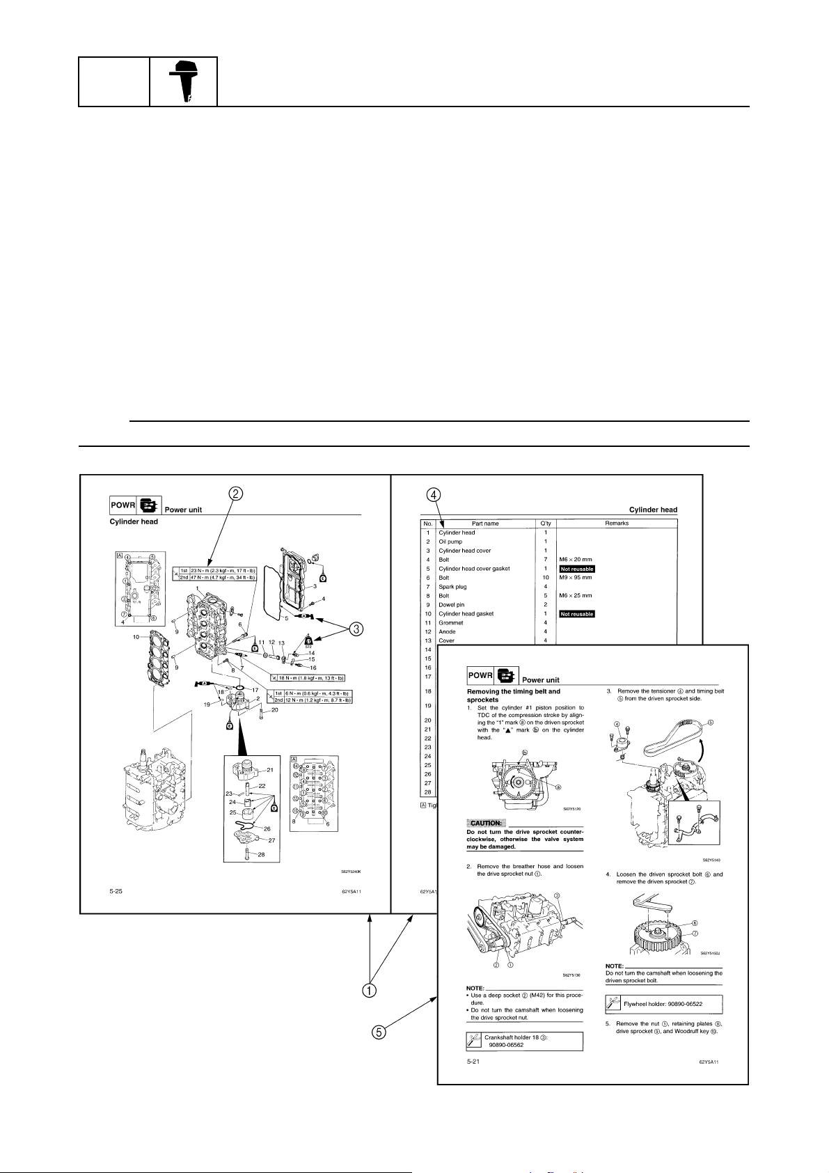
Parts are shown and detailed in an exploded diagram and are listed in the components list.
2
Tightening torque specifications are provided in the exploded diagrams and after a numbered
step with tightening instructions.
3
Symbols are used to indicate important aspects of a procedure, such as the grade of lubricant
and lubrication point.
4
The components list consist of parts and part quantities, as well as bolt screw O-ring and hose
dimensions.
5
Service points regarding removal, checking, and installation are shown in individual illustrations
to explain the relevant procedure.
NOTE:
For troubleshooting procedures, see Chapter 9, “Troubleshooting.”
1
1-1
62Y5A11
T
R
.
.
How to use this manual
Symbols
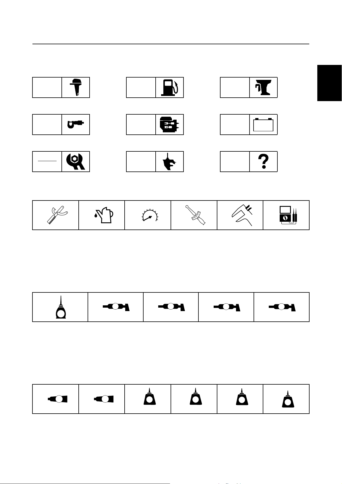
The symbols below are designed to indicate the content of a chapter.
General information
GEN
INFO
Specifications
SPEC
Periodic checks and adjustments
CHK
ADJ
Symbols 1 to 6 indicate specific data.
123456
Fuel system
FUEL
Power unit
POWR
Lower unit
LOWR
Bracket unit
BRKT
Electrical systems
ELEC
Troubleshooting
– +
TRBL
SHTG
1
2
3
4
Special tool
1
Specified oil and fluid
2
Specified engine speed
3
Specified tightening torque
4
Symbols 7 to A in an exploded diagram indicate the grade of lubricant and the lubrication point.
7890A
A M
E
Apply Yamaha 4-stroke motor oil
7
Apply water resistant grease (Yamaha grease A)
8
Apply molybdenum disulfide grease
9
Symbols B to G in an exploded diagram indicate the type of sealant or locking agent and the application point.
BCDEFG
GM
4
LT
271
Specified measurement
5
Specified electrical value
6
(Resistance, Voltage, Electric current)
D C
Apply anti-corrosion grease (Yamaha grease D)
0
Apply low temperature resistant grease
A
(Yamaha grease C)
LT
242
LT
572
SS
5
6
7
8
9
®
Apply Gasket Maker
B
Apply Yamabond No. 4
C
Apply LOCTITE
D
62Y5A11
®
No. 271 (Red LOCTITE)
Apply LOCTITE
E
Apply LOCTITE
F
Apply silicon sealant
G
®
No. 242 (Blue LOCTITE)
®
No. 572
1-2
GEN
INFO
General information
Safety while working
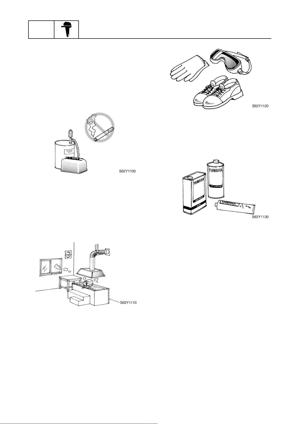
To prevent an accident or injury and to
ensure quality service, follow the safety procedures provided below.
Fire prevention
Gasoline is highly flammable.
Keep gasoline and all flammable products
away from heat, sparks, and open flames.
Ventilation
Gasoline vapor and exhaust gas are heavier
than air and extremely poisonous. If inhaled
in large quantities they may cause loss of
consciousness and death within a short time.
When test running an engine indoors (e.g., in
a water tank) be sure to do so where adequate ventilation can be maintained.
1
Parts, lubricants, and sealants
Use only genuine Yamaha
and sealants or those recommended by
Yamaha, when servicing or repairing the
outboard motor.
Under normal conditions, the lubricants mentioned in this manual should not harm or be
hazardous to your skin. However, you should
follow these precautions to minimize any risk
when working with lubricants.
parts, lubricants,
Self-protection
Protect your eyes by wearing safety glasses
or safety goggles during all operations involving drilling and grinding, or when using an air
compressor.
Protect your hands and feet by wearing protective gloves and safety shoes when necessary.
1-3
1. Maintain good standards of personal and
industrial hygiene.
2. Change and wash clothing as soon as
possible if soiled with lubricants.
3. Avoid contact with skin. Do not, for
example, place a soiled rag in your
pocket.
4. Wash hands and any other part of the
body thoroughly with soap and hot water
after contact with a lubricant or lubricant
soiled clothing has been made.
5. To protect your skin, apply a protective
cream to your hands before working on
the outboard motor.
62Y5A11
6. Keep a supply of clean, lint-free cloths for
wiping up spills, etc.
Good working practices
Special tools
Use the recommended special tools to protect parts from damage. Use the right tool in
the right manner—do not improvise.
Tightening torques
Follow the tightening torque specifications
provided throughout the manual. When tightening nuts, bolts, and screws, tighten the
large sizes first, and tighten fasteners starting
in the center and moving outward.
Non-reusable parts
Always use new gaskets, seals, O-rings, cotter pins, circlips, etc., when installing or
assembling parts.
Safety while working / Identification
3. Install bearings with a manufacture identification mark in the direction indicated in
the installation procedure. In addition, be
sure to lubricate the bearings liberally.
4. Apply a thin coat of water-resistant
grease to the lip and out periphery of an
oil seal before installation.
5. Check that moving parts operate normally after assembly.
Identification
Applicable models
This manual covers the following models.
Applicable models
FT50CEHD, FT50CED, FT50CET
1
2
3
4
1
5
Disassembly and assembly
1. Use compressed air to remove dust and
dirt during disassembly.
2. Apply engine oil to the contact surfaces
of moving parts before assembly.
Serial number
The outboard motor serial number is
stamped on a label attached to the port
clamp bracket.
6
7
8
9
62Y5A11
1-4

GEN
INFO
General information
Model name
1
Approved model code
2
Transom height
3
Serial number
4
Model name
Approved
model code
FT50CEHD
FT50CED L: 550101–
64J
Starting
serial No.
L: 650101–
FT50CET L: 450101–
Features and benefits
Use of leaded gasoline
New FT50C/F50D is designed for pleasure/light commercial use for all over the world. Therefore,
engine components anti-corrosion and reliability has been increased while regular leaded gasoline
is used.
However, always use regular unleaded gasoline for longer engine life.
Newly designed four carburetors
Newly designed four carburetors have been based on the current F50A. Prime Start has been
adopted for the starting system to further increase starting performance and serviceability. Furthermore, the acceleration pump and the dashpot have been integrated to simplify construction and to
ease serviceability. The four carburetors can be accurately and easily adjusted due to the simple
construction of the links.
1
Prime Start
1
Acceleration pump
2
1-5
62Y5A11
Identification / Features and benefits
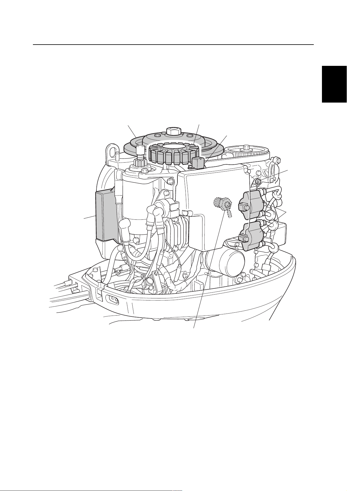
CDI unit with microcomputer
The ignition system consists of a flywheel, stator, pulser coil, thermoswitch, oil pressure switch, CDI
unit, and ignition coil. The CDI unit contains a built-in microcomputer that determines the ignition
timing separately for acceleration and for normal operation, based on signals received from the
pulser coil, thermoswitch, and oil pressure switch.
.
1
1
2
3
4
5
6
2
3
4
5
6
CDI unit
1
Flywheel
2
Stator
3
Pulser coil
4
Thermoswitch
5
Ignition coil
6
Oil pressure switch
7
62Y5A11
7
S62Y1210
7
8
9
1-6
GEN
INFO
Lower unit
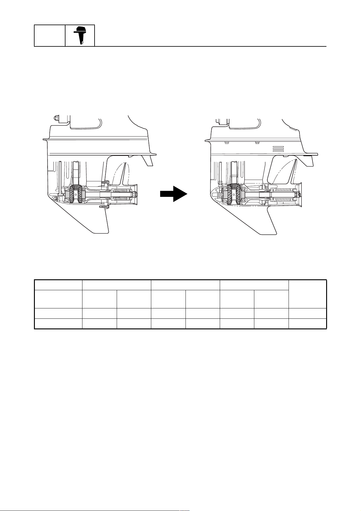
Higher class pinion and gears
The lower unit of the new FT50C uses the same type of large gears that are used in the F100. The
use of the same type of gears that are used in a higher class model provides ample durability, making it possible to accommodate a wider range of applications throughout the market.
General information
F50A FT50C
Pinion Forward gear Reverse gear
Model
F50A 13 45 24 74 24 75 1.8
FT50C 13 46 30 95 30 95 2.3
Number
of teeth
Diameter
(mm)
Number
of teeth
Diameter
(mm)
Number
of teeth
Diameter
(mm)
S62Y1220K
Gear ratio
1-7
62Y5A11
Features and benefits / Technical tips
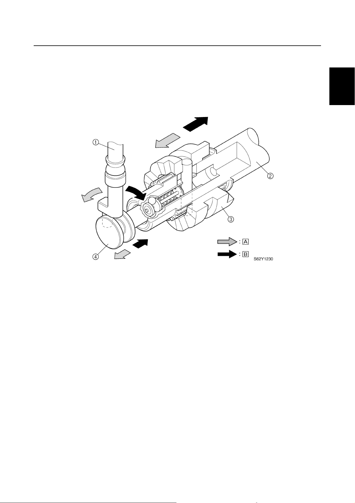
Shift slider type shift mechanism
The FT50C has adopted the shift slider type shift mechanism. This shift mechanism enables a
prompt engagement of the dog clutch regardless of the operating speed of the shift lever. Thus,
smooth and positive shift operation has been made possible.
1
2
3
Shift rod
1
Propeller shaft
2
Dog clutch
3
Shift slider
4
Technical tips
Carburetor
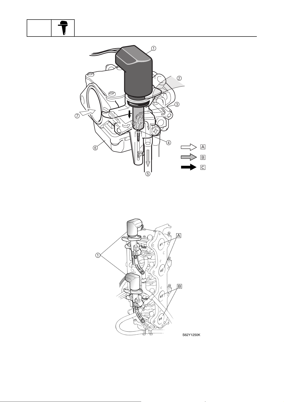
Starting system (Prime Start)
To facilitate the starting of a cold engine, an air-fuel mixture that is richer than normal is required.
For this reason, the Prime Start system has been adopted in the FT50C. In the Prime Start system,
the thermo heater plunger is in a position that fully opens the fuel enrichment valve while the engine
is being started. Thus, fuel enrichment is achieved during the starting of the engine, and continues
while the engine is being warmed up. Once the engine starts, current flows from the lighting coil of
the to the thermo heater, allowing the wax in the Prime Start unit to expand. The expanded wax
moves the thermo heater plunger in the direction to close the enrichment valve. As a result, the volume of fuel that passes through the fuel enrichment valve decreases. A few minutes after the
engine has started, the thermo heater plunger completely closes the fuel enrichment valve, thus
ending the fuel enrichment by the Prime Start system.
Forward
È
Reverse
É
4
5
6
7
1
8
9
62Y5A11
1-8
GEN
INFO
General information
:
:
Prime Start
1
Intake manifold of the engine
2
Thermo heater plunger
3
Fuel enrichment valve
4
To carburetor #2 or #4
5
Carburetor
6
Intake silencer
7
Air
È
Fuel
É
Plunger movement
Ê
:
S62Y1240K
Prime Start
1
The enriched air-fuel mixture is delivered to
È
cylinders #1 and #2 by the Prime Start system
attached to carburetor #1.
1-9
The enriched air-fuel mixture is delivered to
É
cylinders #3 and #4 by the Prime Start system
attached to carburetor #3.
62Y5A11
Technical tips
Carburetor operation
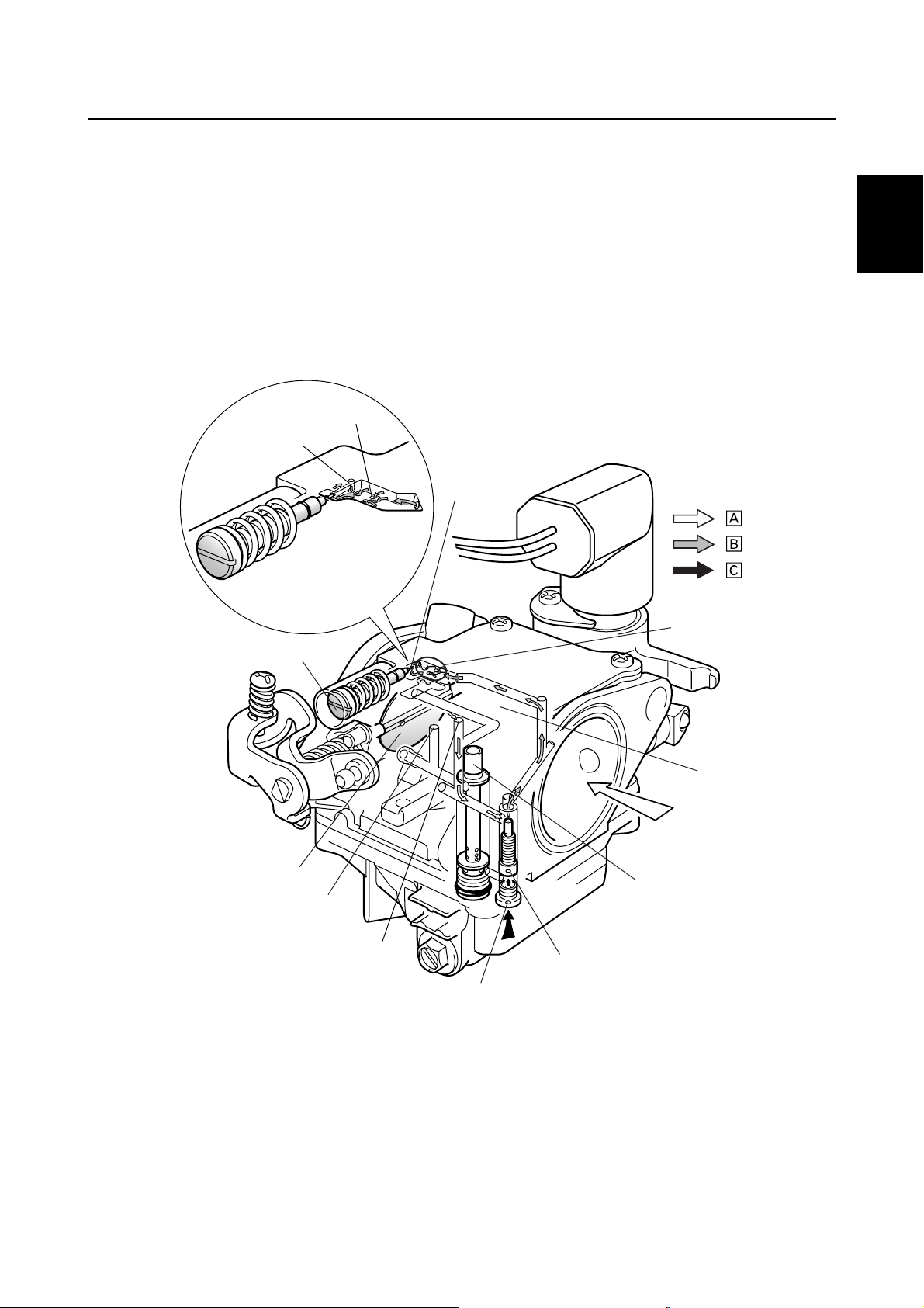
1. Idle and low-speed operation
Since the vacuum at the venturi is low when the throttle valve is opened slightly, the main nozzle
does not supply any air-fuel mixture to the engine.
When the engine is operating at idle, the fuel that passes through the pilot jet and the air that passes
through the pilot air jet mix, enabling the air-fuel mixture that has been regulated by the pilot screw
to be fed through the pilot outlet.
Because the throttle valve opens slightly when the engine is operating at low speeds, air-fuel mixture also starts to be fed from the bypass holes.
3
3
2
2
2
2
:
:
:
:
:
:
1
2
3
4
Pilot screw
1
Pilot outlet
2
Bypass holes
3
Venturi
4
Main nozzle
5
Pilot jet
6
Main jet
7
Pilot air jet
8
1
1
0
0
9
9
8
8
7
7
9
0
È
É
Ê
6
6
Main air jet
Throttle valve
Air
Air-fuel mixture
Fuel
5
5
3
3
4
4
S62Y1260
S62Y1260
5
6
7
8
9
62Y5A11
1-10
GEN
INFO
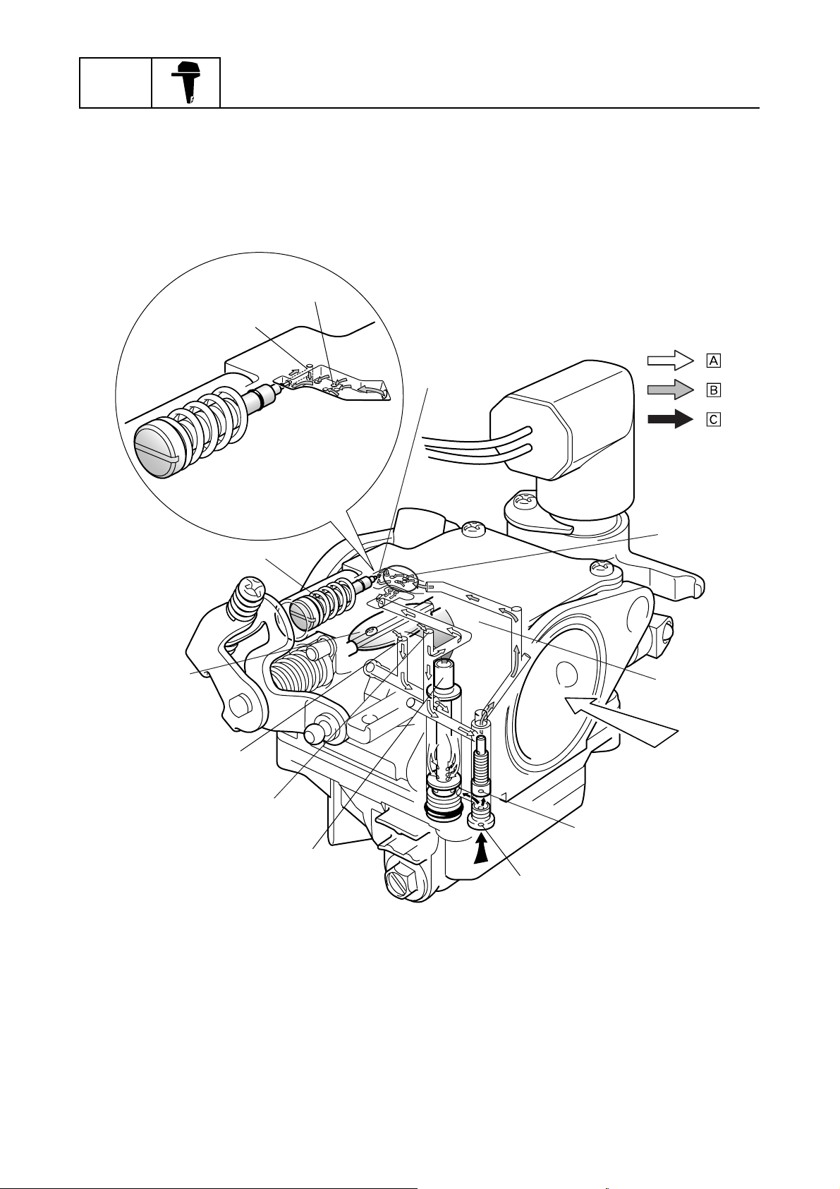
2. Medium speed operation
When the throttle valve opens further, air-fuel mixture is fed from the pilot outlet and all the bypass
holes. In addition, air-fuel mixture is also supplied from the main nozzle in accordance with the
opening angle of the throttle valve.
General information
3
2
2
:
:
:
0
3
1
4
9
8
5
7
6
S62Y1270
Pilot screw
1
Pilot outlet
2
Bypass holes
3
Venturi
4
Pilot jet
5
Main jet
6
Main nozzle
7
Pilot air jet
8
1-11
Main air jet
9
Throttle valve
0
Air
È
Air-fuel mixture
É
Fuel
Ê
62Y5A11
Technical tips
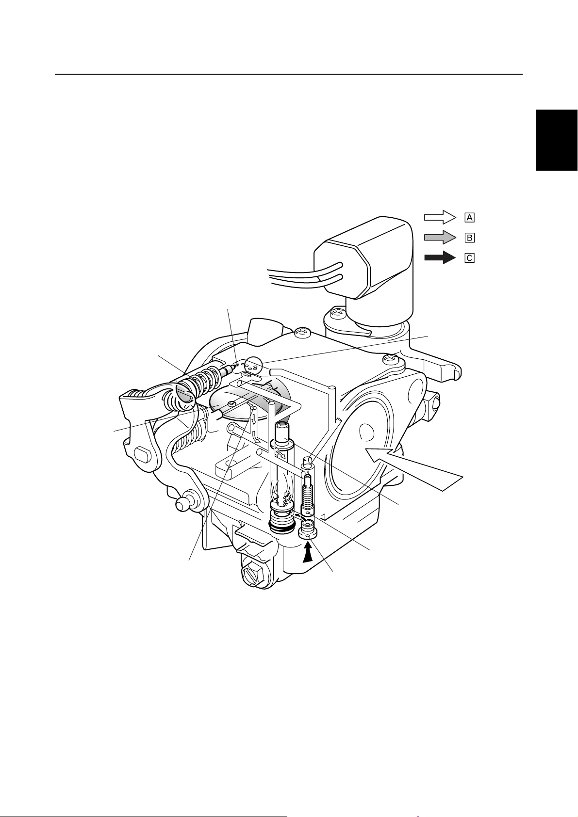
3. High-speed operation
When the throttle valve approaches its fully open position, the fuel that has been regulated by the
main jet and the air that has been regulated by the main air jet are mixed in the main nozzle. The
resultant mixture is then sprayed by the main nozzle into the venturi. The air-fuel mixture that is
sprayed through the venturi is then fed into the engine.
1
8
1
2
3
:
:
:
2
3
4
5
6
Pilot screw
1
Pilot outlet
2
Bypass holes
3
Main nozzle
4
Pilot jet
5
Main jet
6
Main air jet
7
Throttle valve
8
62Y5A11
7
6
Air
È
Air-fuel mixture
É
Fuel
Ê
5
4
7
S62Y1280
8
9
1-12
GEN
INFO
Acceleration pump
The function of the acceleration pump is to ensure a smooth acceleration by preventing the air-fuel
mixture from becoming temporarily lean in case the throttle valve is opened suddenly. When the
throttle valve is opened suddenly, a large volume of air is introduced into the engine. However,
because fuel is heavier than air, it is not possible to supply the volume of fuel that is necessary for
the large volume of air that has been introduced. Thus, because it is not possible to achieve the airfuel mixture that is required by the engine, bucking or hesitation results. For this reason, the acceleration pump temporarily increases the fuel volume in order to adjust the air-fuel mixture to a ratio that
is necessary for the engine in case the throttle valve is opened suddenly.
General information
:
:
Bypass hose
1
Acceleration pump
2
Pump chamber
3
Diaphragm 1
4
Throttle lever
5
Air flow
È
Throttle valve opening direction
É
5
1
2
3
4
S62Y1290
1-13
62Y5A11
Technical tips
Operation
When the throttle is opened suddenly, diaphragm 1 (via the link that is connected to the throttle
lever) operates to pressurize the air in the pump chamber. The pressurized air opens diaphragm 2,
and becomes distributed to the carburetors by passing through the pipes that are connected to the
carburetors. The pressurized and distributed air then utilizes the passage of the main air jet to flow
into the main nozzle. The pressure of the air helps suck fuel from the main jet, which increases the
fuel in the main nozzle, and thus achieves the fuel enrichment.
1
2
:
:
1
2
3
90
A
5
4
8
6
1
A
3
7
2
3
4
5
6
Main air jet
1
Main nozzle
2
Main jet
3
Throttle valve
4
Pilot screw
5
Pilot outlet
6
Pilot jet
7
From acceleration pump
8
Throttle valve closing
9
Throttle valve opening
0
62Y5A11
B
B
Diaphragm 1
A
Diaphragm 2
B
To carburetors
C
Air flow
È
Throttle valve opening direction
É
C
S62Y1300
7
8
9
1-14
GEN
INFO
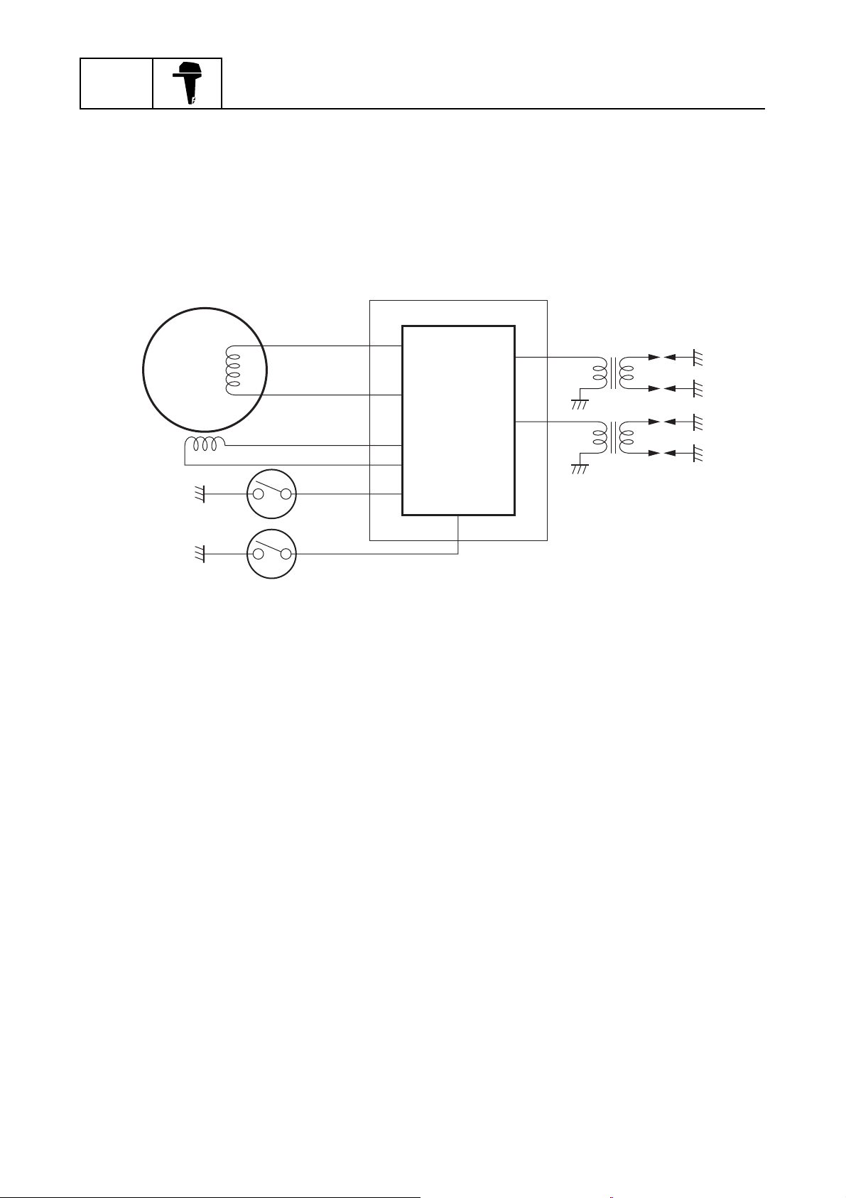
Ignition system
In order to determine the optimal ignition timing that is necessary for the proper operation of the
engine, the built-in microcomputer in the CDI unit detects the signals from various types of sensors
and controls the ignition timing in accordance with a control map that is based on those signals. The
microcomputer also effects controls to protect the engine against overheating, over-revolution, and
oil pressure drops, as well as to control warning devices.
General information
Pulser coil
1
Flywheel
2
Charge coil
3
CDI unit
4
Microcomputer
5
1
2
3
8
9
4
5
Ignition coils #1 and #4
6
Ignition coils #2 and #3
7
Oil pressure switch
8
Thermoswitch
9
6
7
S62Y1310
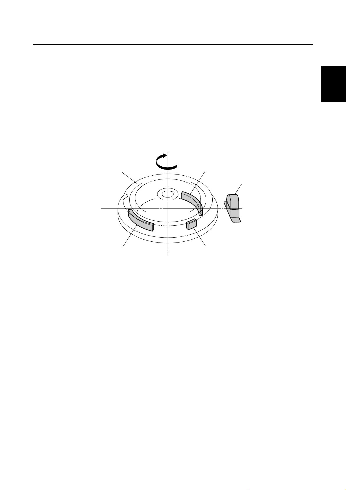
Flywheel
Three protrusions for the pulser coil are provided along the periphery of the flywheel. The purpose
of these protrusions is for detecting the engine speed. Two of them are used for ignition signals, and
one is used for identifying the cylinders, and these signals are transmitted to the microcomputer.
1-15
62Y5A11
Technical tips
Pulser coil
The pulser coil transmits the pulser signals, which are generated in the pulser coil in accordance
with the rotation of the flywheel, to the CDI unit. Among the two protrusions that are provided for
generating signals, one is used for cylinders #1 and #4, and the other for cylinders #2 and #3, thus
enabling the pulser coil to simultaneously ignite two cylinders.
To provide ignition signals to the cylinders, the microcomputer determines the ignition cylinder and
ignition timing. These are based on the cylinder identification signals generated by the protrusion for
identifying cylinders, and on the pulser signals generated by the protrusions for generating ignition
signals.
2
1
2
Flywheel
1
Rotating direction
2
Protrusion for cylinders #1 and #4
3
Pulser coil
4
Cylinder identification protrusion
5
Protrusion for cylinders #2 and #3
6
1
6
3
5
S62Y1320
3
4
4
5
6
7
62Y5A11
8
9
1-16
GEN
INFO
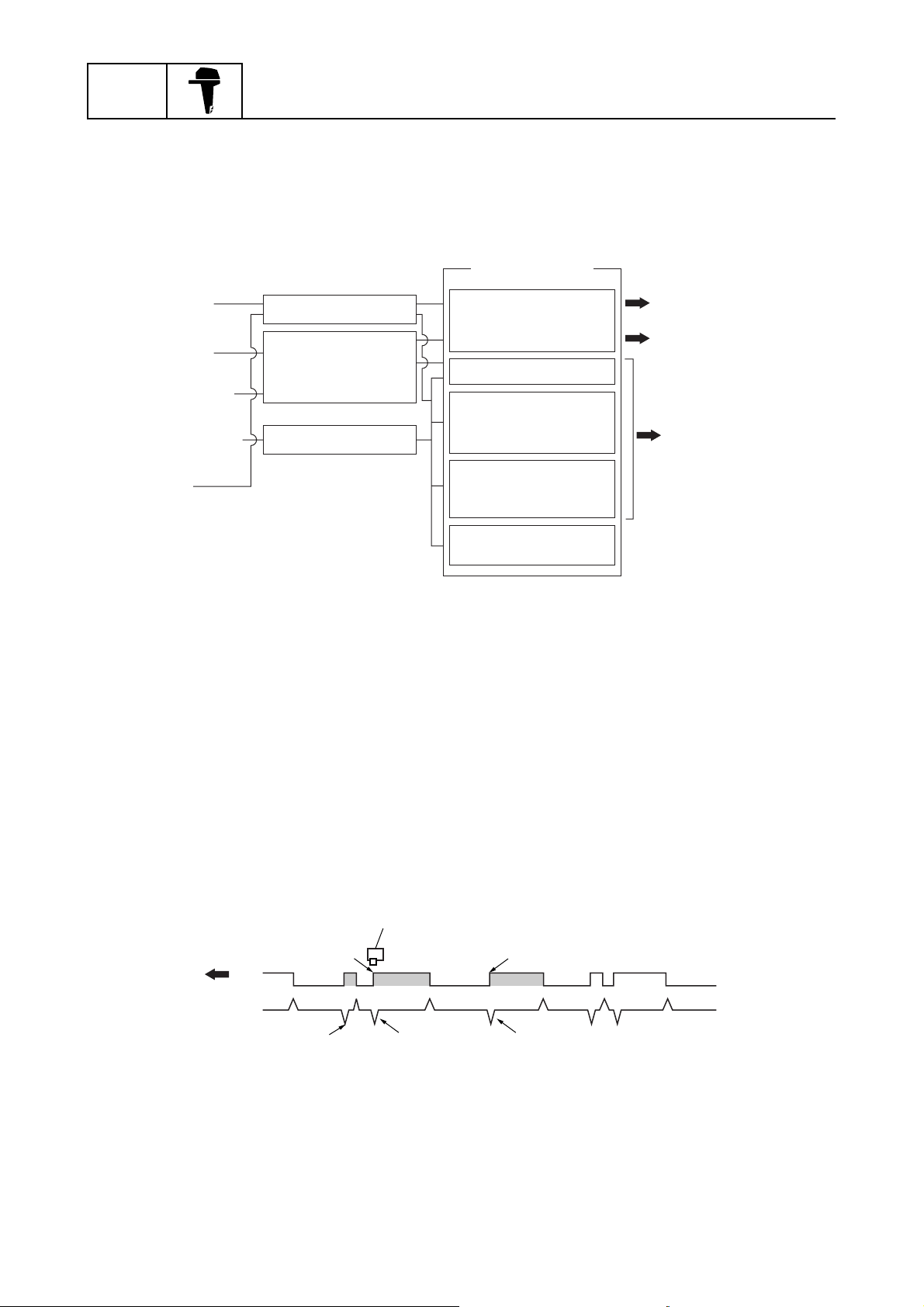
Ignition timing control
Control circuit diagram
General information
Operation
Engine start
Acceleration
Over-revolution
Low oil pressure
Overheat
Detection Microcomputer
Engine temperature
Engine speed
Oil pressure
Ignition timing control
(optimized ignition
timing)
Engine speed control
Warning buzzer
(in remote-control
unit)
Warning lamp
(low oil pressure)
Warning lamp
(to overheat)
Positive start
Quick acceleration
Damage prevention
S62Y1330
Basic control
The ignition timing is determined by using the map based on the engine speed (r/min). Then, ignition signals are output from the microcomputer in accordance with the ignition timing map so that
ignition can take place at the optimal timing in relation to the engine speed. Then, the microcomputer corrects the ignition timing in accordance with the operating conditions of the engine as
detected by the signals that are input from the engine temperature sensor and oil pressure sensor.
The pulser signals that are output when the protrusions for cylinders #1 and #4, and for cylinders #2
and #3 pass by the pulser coil, are used to calculate the engine speed. In addition, the pulser signals are used to determine the forecast starting position of the ignition timing.
9
1
5
Cylinder identification protrusion
1
Pulser coil
2
Protrusion for cylinders #1 and #4
3
Protrusion for cylinders #2 and #3
4
Pulser coil signal
5
1-17
2
34
6
7
8
Cylinder identification signal
6
Identification signal for cylinders #1 and #4
7
Identification signal for cylinders #2 and #3
8
Rotating direction
9
S62Y1340
62Y5A11
Technical tips
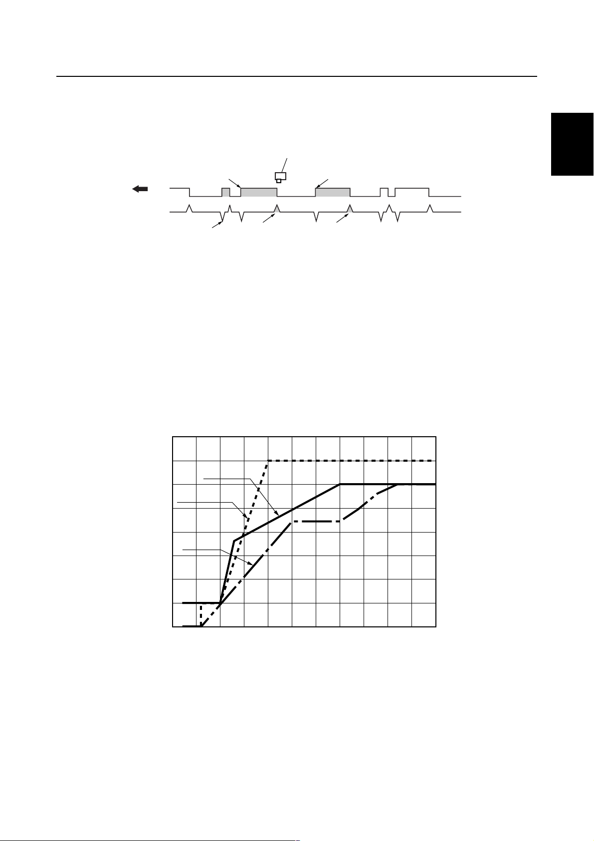
Starting control
When starting the engine, the timing is set to 5° BTDC until the crankshaft speed maintains 600
r/min for two seconds or longer.
3
9
1
5
Cylinder identification protrusion
1
Protrusion for cylinders #1 and #4
2
Pulser coil
3
Protrusion for cylinders #2 and #3
4
Pulser coil signal
5
Cylinder identification signal
6
Warm-up control
After the starting control is completed, the control transfers to the ignition timing based on the warmup map for three minutes. From the time the three-minute warm-up control has been completed, the
control transfers to the normal map.
24
6
7
8
Starting signal (5° BTDC) for cylinders #1 and
7
#4
Starting signal (5° BTDC) for cylinders #2 and
8
#3
Rotating direction
9
S62Y1350
1
2
3
4
5
1
5
0
Ignition timing (BTDC°)
1
Engine speed (× 1,000 r/min)
2
Warm-up map
3
Acceleration map
4
Normal map
5
3
4
5
123456
2
S62Y1360
6
7
8
9
62Y5A11
1-18

GEN
INFO
Acceleration control
This control is activated when the throttle valve is opened suddenly. If the engine speed increases
more than the specified figures, the control of the ignition timing transfers to the acceleration map.
Thereafter, the control of the ignition timing transfers gradually to the control map before acceleration. If it was under warm-up control, the timing transfers to the warm-up control map, and if it was
under normal control, the timing transfers to the normal control map. The control described above
will be repeated if the engine is accelerated again.
Over-revolution control
This control operates by detecting the engine speed. If the engine speed increases to over 6,200
r/min, the ignition of cylinders #1 and #4 is stopped in order to regulate the speed. If the engine
speed increases further to over 6,300 r/min, the ignition of cylinders #2 and #3 is also stopped. This
control will not be deactivated until the engine speed drops below 6,200 r/min.
Overheating control
This control operates in accordance with the engine temperature, which is detected by the signal
that is input from the thermoswitch. When the microcomputer detects via the thermoswitch signal
that the engine temperature has increased to over 80 °C (176 °F), it outputs a signal to stop the ignition of cylinders #1 and #4, if the engine speed is over 2,000 r/min. At the same time, the microcomputer issues a warning by operating the warning lamp and the warning buzzer. When the
overheating control is activated, it will not be deactivated until the engine is stopped or the engine
temperature decreases to under 70 °C (158 °F).
The determination of overheating stops when the engine is stopped. However, until the engine temperature decreases to approximately 70 °C (158 °F) or below, the overheating control will be activated upon restarting the engine. Upon restarting, if the engine speed is under 2,000 r/min, the
overheating control will not be activated for 75 seconds. However, if the engine is operated at over
2,000 r/min for more than 25 seconds, the overheating control will be activated.
Oil pressure control
The oil pressure control operates in accordance with the signals from the oil pressure switch. The oil
pressure is determined to have dropped if the engine continues to operate at over 2,000 r/min with
an oil pressure of under 49 kPa (0.49 kgf/cm
pressure control is activated, the warning buzzer sounds and the warning lamp illuminates. If the
engine speed is over 2,000 r/min, the control stops the ignition of cylinders #1 and #4 so that the
engine speed will not increase to over 2,000 r/min. Once an oil pressure drop is determined, this
control will not be deactivated even if the oil pressure recuperates, until the engine is stopped.
General information
2
, 6.97 psi) for more than one second. When the oil
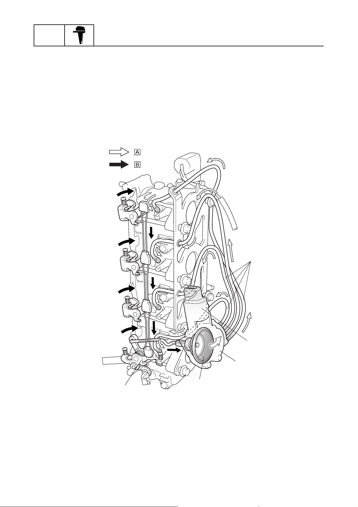
Power trim and tilt
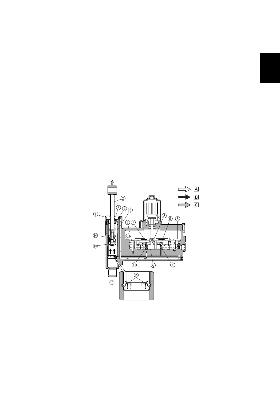
The newly designed power trim and tilt consists of an up-main valve, a down-main valve, an uprelief valve, a single cylinder, and a single ram, which control both trim and tilt functions.
The power trim and tilt cylinder has been integrated with the gear pump housing, the reservoir tank,
and the power trim and tilt motor in order to achieve a smaller and more compact unit.
1-19
62Y5A11
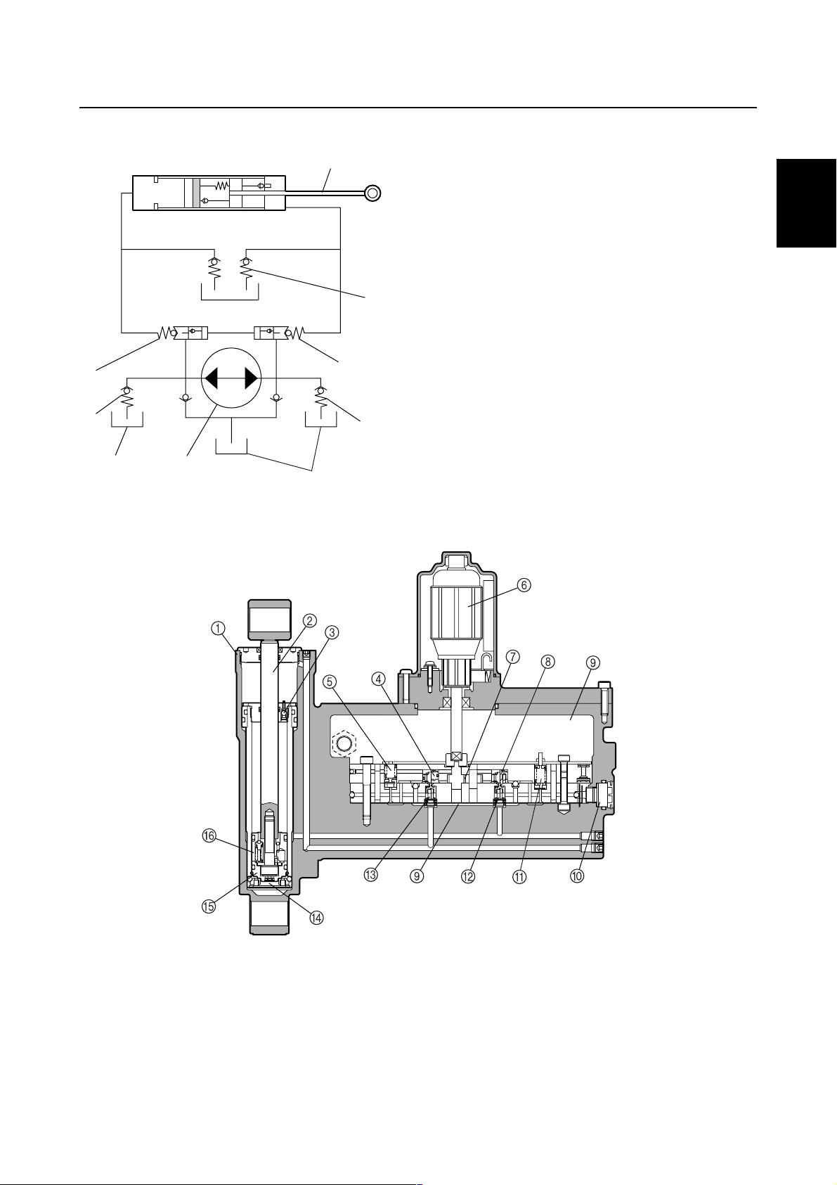
Hydraulic system diagram
1
3
2
4
Power trim and tilt cylinder
1
Ram
2
Reservoir
3
Manual valve
4
Down-main valve
5
Down-relief valve
6
Hydraulic pump
7
Up-relief valve
8
Up-main valve
9
Technical tips
1
2
9
8
73
Power trim and tilt components
3
5
6
S62Y1370
3
4
5
6
Cylinder
1
Ram
2
Check valve
3
Down-main valve
4
Down-relief valve
5
Motor
6
Gear pump
7
Up-main valve
8
62Y5A11
Reservoir
9
Manual valve
0
Up-relief valve
A
Up-shuttle piston
B
Down-shuffle piston
C
Trim cylinder base
D
Free piston
E
Tilt piston
F
7
8
S62Y1380K
9
1-20
GEN
INFO
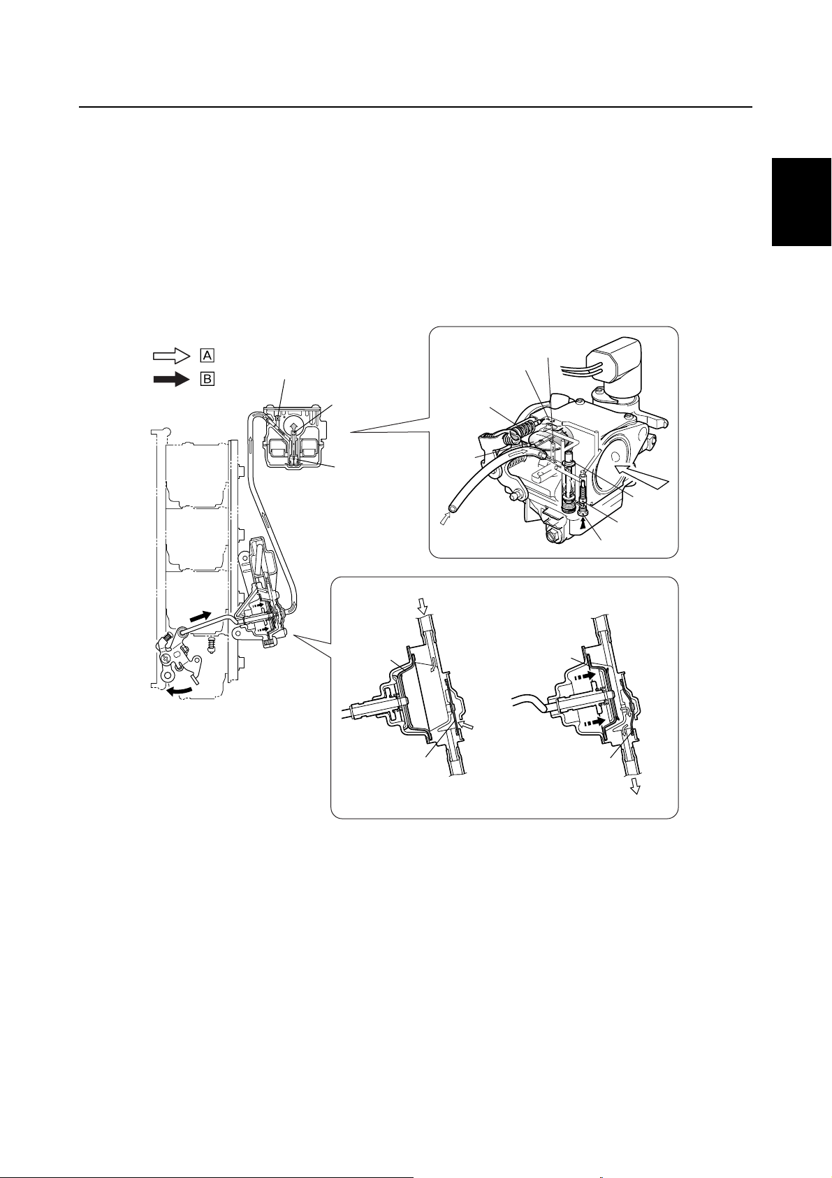
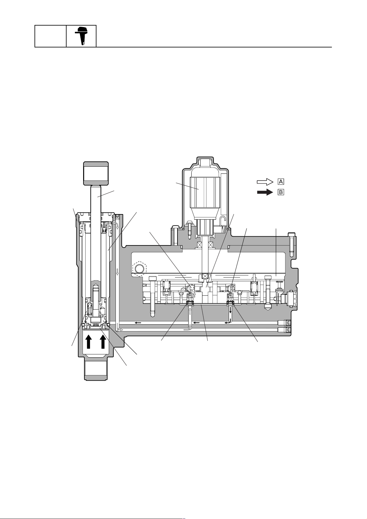
Trim-up function
The gear pump pumps power trim and tilt fluid to the up-main valve. As a result, the fluid pressure
opens the up-shuttle piston causing the fluid to flow into the lower part of the power trim and tilt cylinder. At the same time, vacuum from the gear pump opens the down-main valve and down-shuttle
piston, which causes fluid from the upper part of the power trim and tilt cylinder to return to the gear
pump, and also sucks fluid in through the reservoir.
The pressurized fluid forces up the trim cylinder along with the tilt piston, free piston, and trim cylinder base. As the trim cylinder moves up, the ram extends and the outboard motor is trimmed up.
The end of the trim range is when the trim cylinder tops out in the power trim and tilt cylinder.
General information
1
C
2
3
A
4
0
5
8
6
7
:
:
8
9
Power trim and tilt cylinder
1
Ram
2
Trim cylinder
3
Down-main valve
4
Motor
5
Gear pump
6
Up-main valve
7
Reservoir
8
1-21
B
Up-shuttle piston
9
Down-shuttle piston
0
Free piston
A
Trim cylinder base
B
Tilt piston
C
Return
È
Send
É
S62Y1390
62Y5A11
Technical tips
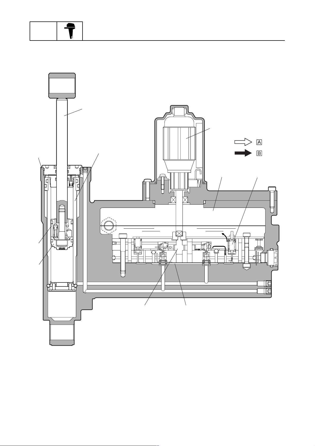
Trim-down function
When the power trim and tilt switch is pressed to “Down”, the motor turns the gear pump counterclockwise and the power trim and tilt fluid flows in the opposite direction to that of the trim-up function.
Tilt-up function
When the trim cylinder tops out, the check valve is pushed down by the end screw wall. This causes
the ball in the check valve to move down, opening the fluid passage and allowing the power trim and
tilt fluid to flow from the upper part of the trim cylinder, through the down-shuttle piston and the
down-main valve, and back to the gear pump. In addition, fluid is also sucked in through the reservoir and the pressurized fluid continues to flow into the lower part of the trim cylinder, pushing up the
tilt piston and free piston, and further extending the ram.
As the tilt piston moves up and off of the trim cylinder base, the base moves up and pushes the balls
outward to fit into holes of the power trim and tilt cylinder. Once the balls have been fitted into the
holes the trim cylinder base cannot move.
The end of the tilt-up range is when the tilt piston tops out in the trim cylinder and the ram is fully
extended.
The tilt-up function operates when the fluid pressure is under 10 MPa (100 kgf/cm
When the fluid pressure in the lower part of the trim cylinder increases to over 10 MPa (100 kgf/cm
1,423 psi), the up-relief valve opens and allows the pressurized fluid to flow into the reservoir. Thus,
the tilt piston and free piston are not pushed up and the ram cannot be extend further.
2
, 1,423 psi).
1
2
3
2
,
4
Power trim and tilt cylinder
1
Ram
2
End screw
3
Check valve
4
Trim cylinder
5
Reservoir
6
Down-main valve
7
Gear pump
8
Up-main valve
9
Up-shuttle piston
0
Down-shuttle piston
A
Trim cylinder base
B
Free piston
C
Tilt piston
D
Balls
E
Return
È
Send
É
Moving direction
Ê
:
:
:
S62Y1400K
5
6
7
8
9
62Y5A11
1-22
GEN
INFO
Circular flow
General information
2
4
:
1
9
8
3
5
:
6
Power trim and tilt cylinder
1
Ram
2
Trim cylinder
3
Motor
4
Reservoir
5
Up-relief valve
6
1-23
7
Gear pump
7
Free piston
8
Tilt piston
9
Return
È
Send
É
5
S62Y1410
62Y5A11
Technical tips
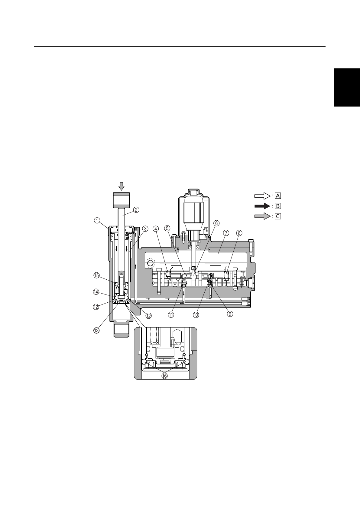
Tilt-down function
When the power trim and tilt switch is pressed to “Down”, the motor turns the gear pump counterclockwise, thus pumping the power trim and tilt fluid to the down-main valve. As a result, fluid pressure opens the down-main valve and the down-shuttle piston, which causes fluid to flow into the
upper part of the trim cylinder and forces the tilt piston down.
When the tilt piston and the free piston reach the trim cylinder base, it pushes the base down, allowing the balls to move inward. Once the balls move in, the trim cylinder is then able to move down
and power trim and tilt fluid continues to flow into the cylinder and pushes the trim cylinder down,
along with the tilt piston and ram.
The end of the tilt-down range is when the tilt piston and the free piston bottom out in the trim cylinder base. When the power trim and tilt fluid pushes the trim cylinder down further trim-down is
started. The end of the trim-down range is when the trim cylinder arrives at the bottom of the power
trim and tilt cylinder. Before the trim cylinder arrives at the bottom of the power trim and tilt cylinder,
an amount of fluid equal to the volume of the ram is returned to the reservoir.
1
2
3
S62Y1420K
4
5
6
7
8
Power trim and tilt cylinder
1
Ram
2
Trim cylinder
3
Down-relief valve
4
Down-main valve
5
Gear pump
6
Reservoir
7
Up-relief valve
8
Up-shuttle piston
9
Up-main valve
0
62Y5A11
Down-shuttle piston
A
Ball
B
Trim cylinder base
C
Free piston
D
Tilt piston
E
Balls
F
Return
È
Send
É
Moving direction
Ê
9
1-24
GEN
INFO
Stopping condition
When the power trim and tilt switch is not pushed (released), the gear pump does not pump the
fluid, the up-main valve and the down-main valve are closed, and the power trim and tilt fluid pressure in the system remains constant. This allows the ram to maintain its position until the power trim
and tilt fluid flows through the system again.
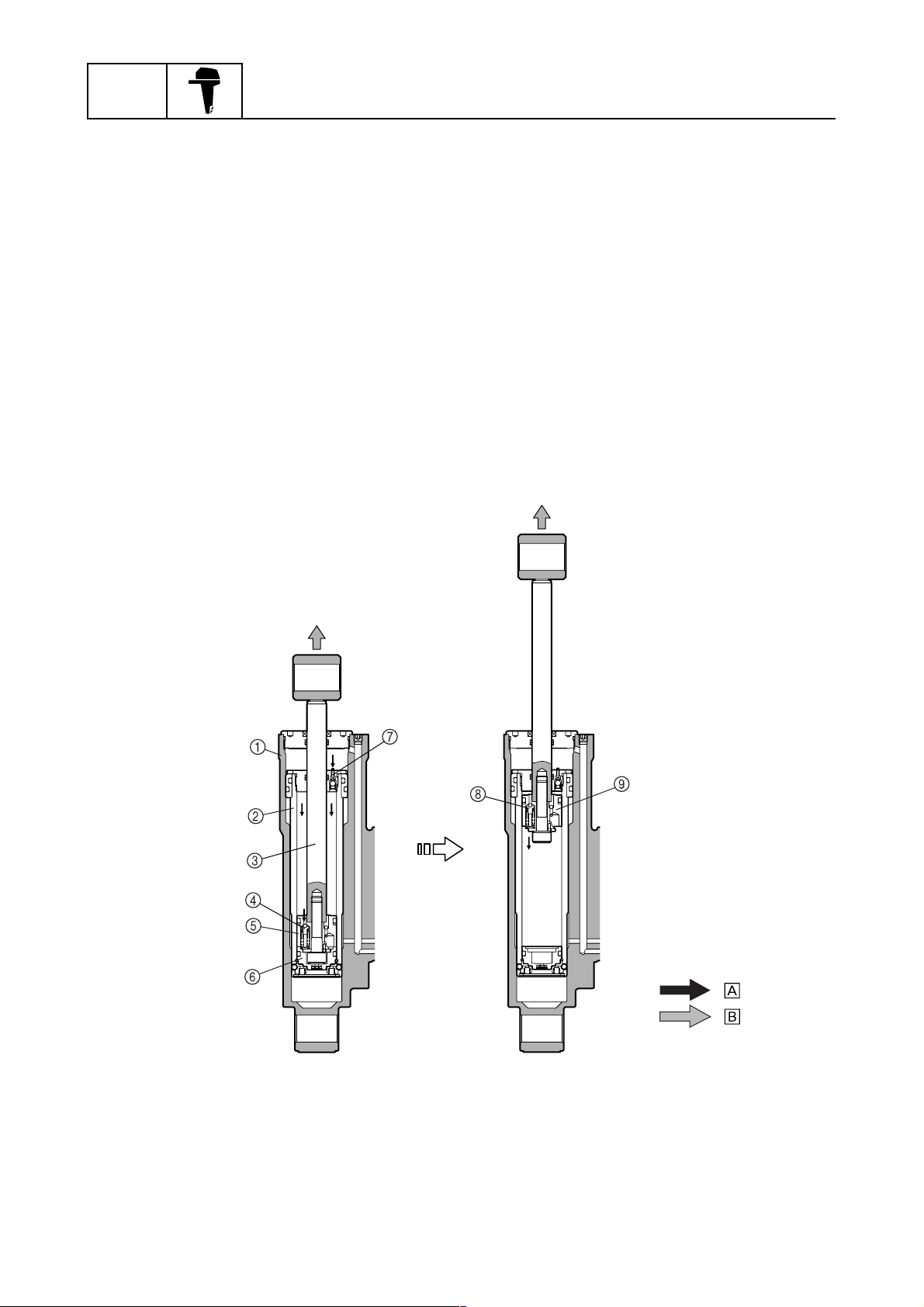
When the outboard motor hits something in the water
The check valve of the trim cylinder and the tilt piston absorber of the tilt piston help to prevent internal damage to the power trim and tilt unit and help to protect the bracket and lower unit from damage in case the outboard motor hits something during operation.
When the outboard motor hits something, highly pressurized fluid in the upper part of the power trim
and tilt cylinder pushes down the check valve of the trim cylinder. At the same time, fluid pressure in
the upper part of the trim cylinder increases and the tilt piston absorber is pushed down. As a result,
the tilt piston and the ram are pushed up without the free piston. The tilt piston is stopped before
reaching the top of the trim cylinder by the damper function of the tilt piston absorber to protect the
power trim and tilt unit from damage.
Damper function
General information
Power trim and tilt cylinder
1
Trim cylinder
2
Ram
3
Tilt piston absorber
4
Tilt piston
5
Free piston
6
1-25
Check valve
7
Tilt piston absorber
8
Tilt piston
9
Send
È
Moving direction
É
:
:
S62Y1430K
62Y5A11
 Loading...