

Page 1
Page 2
Page 3
Page 4
Page 5

Page 6

ENGLISH
• Thank you for purchasing the YAMAHA EQ-1100/U
graphic equalizer.
WARNING
TO PREVENT FIRE OR SHOCK HAZARD, DO NOT
EXPOSE THIS APPLIANCE TO RAIN OR
MOISTURE.
CAUTION: READ THIS BEFORE OPERATING
YOUR UNIT.
1. The EQ-1100/U is a sophisticated graphic equalizer.
To ensure proper operation for the best possible
performance, please read this manual carefully.
2. Choose the installation location of your unit carefully.
Avoid placing it in direct sunlight or close to a source of
heat. Also avoid locations subject to vibration and
excessive dust, heat, cold or moisture. Keep it away from
such sources of hum as transformers or motors.
3. Do not install the unit on other component and do not
place the television set or color monitor on the unit.
4. Do not open the cabinet as this might result in damage
to the set, or electrical shock. If a foreign object should get
into the set, contact your dealer.
5. To prevent lightning damage, pull out the power cord
during an electrical storm.
6. When removing the power plug from the wall outlet,
always pull directly on the plug; never pull the cord itself.
7. Do not use force when using the switches.
CAUTION: TO PREVENT ELECTRIC SHOCK DO
NOT USE THIS (POLARIZED) PLUG WITH AN
EXTENSION CORD, RECEPTACLE OR OTHER
OUTLET UNLESS THE BLADES CAN BE FULLY
INSERTED TO PREVENT BLADE EXPOSURE.
SPECIAL INSTRUCTIONS FOR BRITISH
MODEL
IMPORTANT:
The wires in the mains lead are coloured in
accordance with the following code.
Blue: NEUTRAL
Brown: LIVE
As the colours of the wires in the mains lead of this
apparatus may not correspond with the coloured
markings identifying the terminals in your plug, proceed
as follows. The wire which is coloured BLUE must be
connected to the terminal which is marked with the
letter N or coloured BLACK. The wire which is coloured
BROWN must be connected to the terminal which is
marked with the letter L or coloured RED.
8. When moving the set be sure to first pull out the power
plug and remove cords connected to other equipment.
9. Do not attempt to clean the unit with chemical solvent
as this might damage the finish. Use a clean, dry cloth.
10. Be sure to read the "Troubleshooting" section for
advice on common operating errors before concluding
that your unit is faulty.
11. Keep this manual in a safe place for future reference.
12. Voltage selector (General model only) The voltage
selector switch on the rear panel of this unit must be set for
your local mains voltage before plugging in the AC main
supply.
Page 7

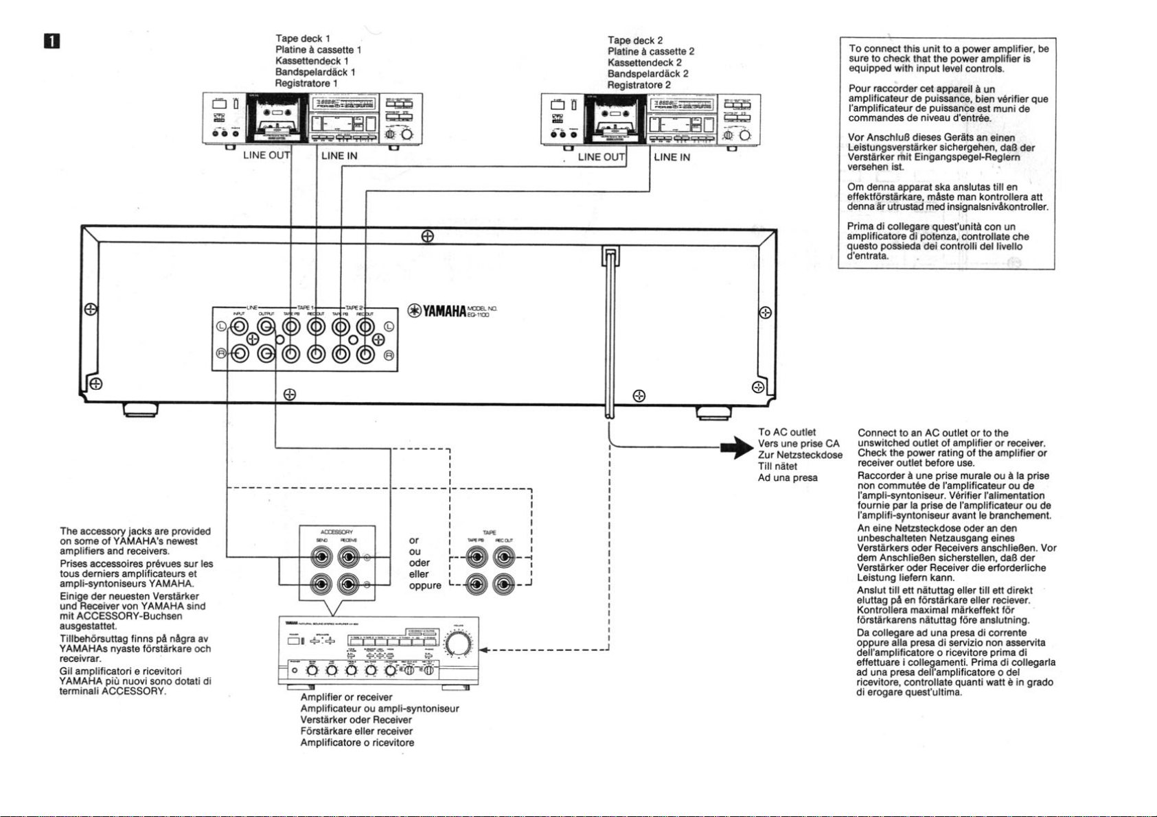
CONNECTIONS
(See Fig. 1.)
• When connecting your equipment, turn the power to
each unit off and make sure that you have correctly
connected the Left (L) and Right (R) channels.
• For the amplifier or receiver connections, please refer to
the amplifier or receiver owner's manual.
■ CONNECTING AN AMPLIFIER OR
RECEIVER
Check from the connection diagram that you have made
the correct connections. Please note that input procedures
and program source selection may vary according to the
capabilities of the amplifier or receiver and the
connections between it and this unit.
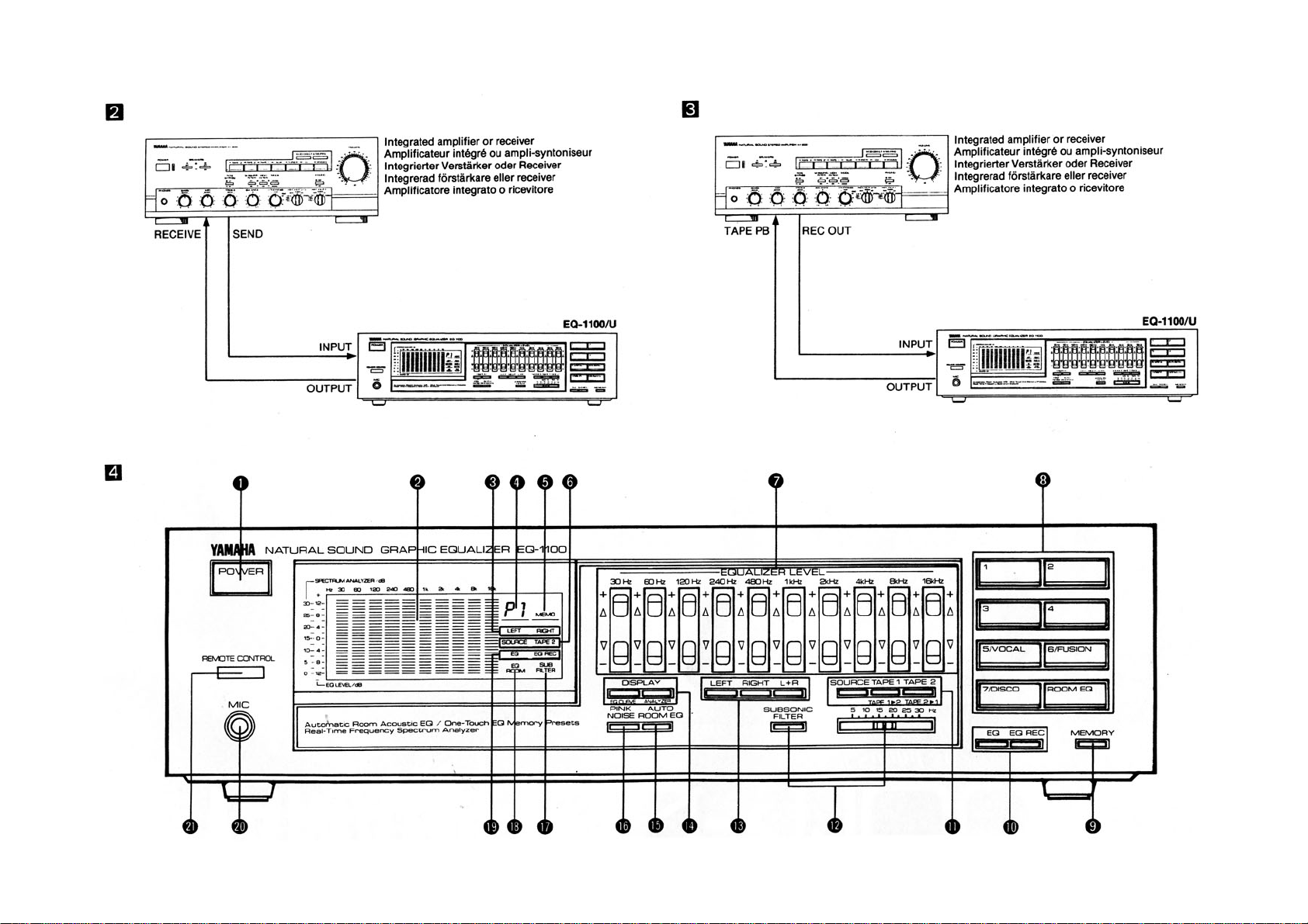
• To connect an integrated amplifier or receiver using
the ACCESSORY jacks (See Fig. 2.):
The ACCESSORY jacks are provided on some of
Yamaha's newest amplifiers and receivers.
1. Connect the SEND jacks of the ACCESSORY jacks to
the LINE INPUT of this unit.
2. Connect the RECEIVE jacks of the ACCESSORY jacks
to the LINE OUTPUT of this unit.
The program source selected with the integrated
amplifier's or receiver's input selector can be equalized.
• To connect an integrated amplifier or receiver
without using the ACCESSORY jacks (See Fig. 3):
1. Connect the REC OUT jacks of the TAPE jacks to the
LINE INPUT of this unit.
2. Connect tne TAPE PB jacks of the TAPE jacks to the
LINE OUTPUT of this unit.
The following operations can be carried out via the
amplifier or receiver:
Amp
With a REC
OUT selector.
\ With a TAPE
MONITOR
switch.
Program Source
Selected with the
REC OUT Selector.
Selected with the
input selector.
Setting
Set the INPUT
SELECTOR to
TAPE.
Turn the TAPE
MONITOR switch
ON.
■ CONNECTING A TAPE DECK
Connect the tape deck to the TAPE jacks. Connect the
TAPE PB jacks to the tape deck's LINE OUT terminal, and
the REC OUT jacks to the tape deck's LINE IN jacks.
FRONT PANEL PARTS
AND FUNCTIONS
(See Fig. 4.)
1. POWER switch
Press this switch to turn the unit ON. Press the switch
again to turn the unit OFF.
NOTE
Even when the equalizer is not in use, be sure that the
power cord is connected and the POWER switch is set to
ON.
Failure to do so may result in no sound or distorted sound.
2. SPECTRUM ANALYZER/EQ LEVEL display
The spectra or equalizer levels are displayed.
The spectra are displayed using bars while the equalizer
levels are displayed using dots.
When a microphone is connected to the MIC jack, the
spectra of the microphone input are displayed.
3. Channel indicators
During equalizer display:
LEFT: Lights when the left channel is selected with the
channel button.
RIGHT: Lights when the right channel is selected with the
channel button.
LEFT RIGHT: The two light when the left and right
channels are selected with the channel button.
During analyzer display:
LEFT: Lights when the left channel is selected with the
channel button.
RIGHT: Lights when the right channel is selected with the
channel button.
LEFT + RIGHT: Light when the left and right channels
are selected with the channel button.
4. Preset No. indicator
The preset memory number (P1 to P7) is displayed.
5. MEMO indicator
When the MEMORY button is pressed, this indicator
flashes for about 5 seconds.
Page 8

6. Input Indicators
The source selected by the input select buttons is
indicated.
7. EQUALIZER LEVEL buttons
Independent level controls for the right, left or both
channels are provided for each of the ten frequency bands
with a ±12 dB range of equalization. These button
operations are effective only when the EQ button is set to
ON even during the display changes.
• 30 Hz band
Decreasing this level eliminates very low frequency
rumble, or compensates a warped disc.
Increasing this level emphasizes the very low frequencies.
• 60 Hz band
Decreasing this level reduces AC line hum and the lower
tone.
Increasing this level emphasize low tones, such as pipe
organ, drums, bass, etc.
• 120 Hz band
This range supports the lower end of the music and
controls overall depth. Decrease this level to eliminate
"boomy bass" caused by room acoustics.
• 240 Hz band
This is the middle-to-lower tone range, but it has an effect
on the overall sound. Mainly, the richness of the strings can
be controlled. When strings are overly warm under actual
listening conditions, decrease this level.
• 480 Hz band
This range is the foundation of music including both
instruments and the human voice and it controls the
overall power of the sound. As this level is increased,
midrange sound will become more forward.
• 1 kHz band
This range affects the presence of the music (depth of
tone), and is especially effective when playing back
vocals. Increasing or decreasing this level will cause the
vocals to be more "up front" or more reserved.
• 2 kHz band
This is the frequency range where the human ear is most
sensitive. Boosting the level slightly will add brilliance,
crispness, etc. to instruments. Cutting the level slightly
makes for easy listening.
• 4 kHz band
The human ear is also highly sensitive in this range. Mainly
effective for increasing/decreasing the harmonics of the
primary tone. Boosting this range a bit makes strings more
intense. Over-intense, tiresome music is easily listened to
when the level is decreased.
• 8 kHz band
High frequency range. Strings, horns, etc. will be
emphasized and this gives a slight difference in tone glaze
and quality. Decreasing the level reduces overemphasized
consonants in vocals and objectionable tape hiss.
Increasing the level, on the other hand, improves the
sharpness of such instruments as cymbals.
• 16 kHz band
Super-high frequency range. This affects high harmonics
rather than the fundamental tones of the instruments
themselves, and has an effect on the delicacy and
atmosphere of the music. Boosting this level adds a
delicate, fresh sound to cymbals, triangles, etc.
8. Preset memory buttons
These buttons are used to store equalizer curves in the
preset memory. By storing desired curves in the memory,
they can be recalled by pressing these buttons. Up to 4
equalizer curves can be stored in memory. In addition,
three memories are provided with storage of equalizer
curves that are optimized for VOCAL, FUSION and DISCO
music. These are stored under memory buttons 5 to 7, and
cannot be rewritten by the user. The equalizer curve
obtained by auto equalization is automatically stored under
the ROOM EQ button.
9. MEMORY button
To store the equalizer curve being displayed in memory,
press this button. Then, while the MEMO indicator is
flashing (for about 5 seconds), press one of preset
memory buttons (1 — 4).
10. EQ button and EQ REC button
To start equalization of a sound, press the EQ button so
that the EQ indicator lights.
To record the equalized sound, press the EQ button then,
the EQ REC button so that the EQ REC indicator lights.
11. Input select buttons
Press one of these buttons to select the source to be
listened to.
SOURCE: To play the source connected to the amplifier,
or to record onto cassette deck 1 or 2.
TAPE1: To play cassette deck 1 connected to the
equalizer, or to dub the sound to cassette deck 2.
TAPE2: To play cassette deck 2 connected to the
equalizer, or to dub the sound to cassette deck 1.
12. SUBSONIC FILTER button and control
Used to cut off unnecessary low frequency. If the program
source to be played contains such super low sound, press
the SUBSONIC FILTER button to turn the subsonic filter
ON. The frequency to be cut off can be adjusted by the
slide control.
13. Channel buttons
These are used to select the channel(s) subject to the
equalizer level control or spectrum display.
LEFT: To display the equalizer levels or spectrum of the
left channel only.
RIGHT: To display the equalizer levels or spectrum of the
right channel only.
L + R: To display the equalizer levels or spectrum of both
the left and right channels. With the equalizer level
display, the left channel levels are displayed more
brightly than the right channel levels. With the spectrum
display, the sum of the left and right spectra is
displayed.
14. DISPLAY mode buttons
These are used to select the display mode.
EQ CURVE: To display the equalizer levels.
ANALYZER: To display the spectrum.
15. AUTO ROOM EQ button
Press for auto equalization.
This button functions only when the supplied microphone
is connected to the MIC jack.
Page 9

16. PINK NOISE button
Pink noise, which is emitted by a built-in generator, is a
random noise signal which is distributed at an even level at
all frequencies, and when monitored through the supplied
microphone, allows you to measure the acoustic response
characteristics of the listening environment. To emit pink
noise, set this button to ON and press the channel button
to select the channel to which pink noise is applied.
17. SUB (subsonic filter) indicator
Lights when the SUBSONIC FILTER button is ON.
18. ROOM EQ indicator
Lights when the ROOM EQ button is ON.
The indicator flashes when the AUTO ROOM EQ button is
ON, to indicate the auto equalization operation.
19. EQ/EQ REC indicators
Light respectively when the EQ and EQ REC buttons are
ON.
However, when the EQ button is pressed OFF while the
EQ and EQ REC buttons have been ON, the EQ REC
indicator also goes off.
20. MIC jack
Connect the supplied microphone to this jack to measure
acoustic characteristics of the listening room or to perform
auto equalization. Note that the supplied microphone is
not for sound mixing.
21. REMOTE CONTROL sensor
The signal from the provided remote control transmitter is
received through this window.
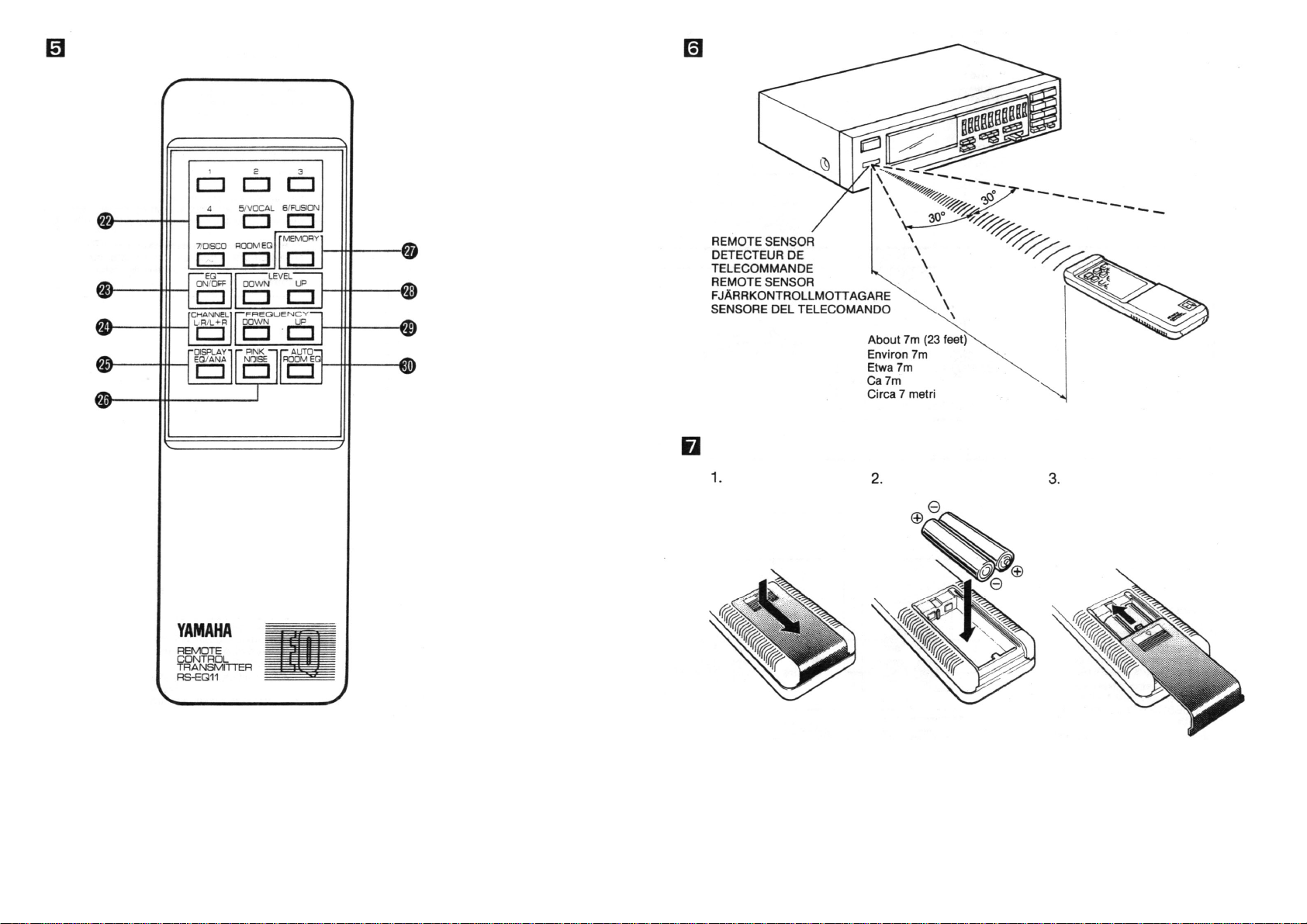
■ REMOTE CONTROL TRANSMITTER
(See Fig. 5)
22. Preset memory keys
23. EQ ON/OFF key
24. CHANNEL keys
25. DISPLAY mode key
26. PINK NOISE key
27. MEMORY key
28. LEVEL UP/DOWN keys
After selecting a frequency with the remote control
transmitter's FREQUENCY UP/DOWN keys or the main
unit's EQ LEVEL buttons, adjust the level of the frequency
with these keys.
29. FREQUENCY UP/DOWN keys
These are used to select the frequency subject to manual
adjustment of the equalizer level. In the equalizer level
display mode, the dot of the level selected lights with high
brightness for about 7 seconds. In the analyzer display
mode, the lowest bar lights with high brightness for about
7 seconds.
30. AUTO ROOM EQ key
REMOTE CONTROL TRANSMITTER
With the supplied remote control transmitter, most
operations can remotely be carried out and the sound
quality can be adjusted at your listening position.
■ REMOTE CONTROL OPERATION RANGE
(See Fig. 6.)
The remote control transmitter can be used up to about 23
feet from your amplifier and must be aimed in its direction
for proper operation.
When the distance of the remote control range becomes
short, replace the batteries.
■ BATTERY INSTALLATION
(See Fig. 7)
Install the supplied batteries as shown below.
1. Remove the battery compartment lid in the direction of
the arrow.
2. Install the supplied batteries with the correct polarities.
3. Slide in the battery compartment lid until it clicks.
■ ELECTRET CONDENSER MICROPHONE
(See Fig. 8.)
An electret condenser microphone for auto equalization is
provided with this unit. Microphone input will be displayed
on the spectrum analyzer when the microphone is
connected to the front panel MIC jack, the microphone
switch is turned on, and a signal of level high enough to be
measured is output through the speakers. * Remove the
battery from the microphone if you do not expect to be
using it for some time.
Page 10
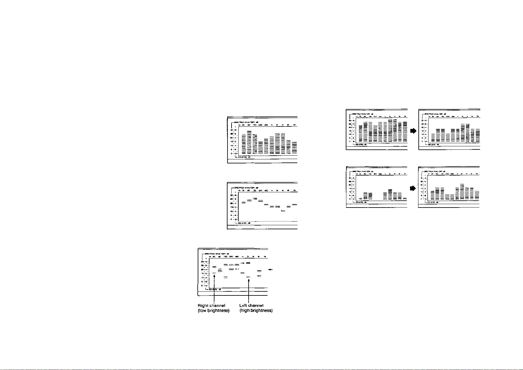
High-brightness display in
•
EQUALIZER LEVEL DISPLAY (LEFT) OR (RIGHT)
•
EQUALIZER LEVEL DISPLAY (LEFT RIGHT)
•
WHEN INPUT LEVEL IS LOW
Changing the battery (See Fig. 9.)
© Remove the cover.
(2) Insert battery (size "AA", R06), or equivalent making
sure that the positive and negative poles are facing in
the right direction.
(3) After the battery has been changed snap the lid back
on.
If the battery runs down, the sensitivity of the microphone
will decrease. Change the battery as soon as it starts to
run down.
BEFORE OPERATION
■ DISPLAY MODES
The display modes include the spectrum mode and
equalizer level mode.
• SPECTRUM DISPLAY (LEFT), (RIGHT), (LEFT +
RIGHT)
■ AUTO-LEVELING FUNCTION
If the spectrum level becomes too high or too low due to
the influence of the input signal level, the auto-leveling
function adjusts the spectrum display level in three steps
(0 dB, -6 dB, -12 dB) so that the spectrum is always at the
center of the display.
• WHEN INPUT LEVEL IS HIGH
Battery Cautions
If the battery is replaced incorrectly, dangerous leakage
or corrosion may result. Be especially careful of the
following points:
When replaceing:
• Insert the battery with correct (+) and (-) indications
correctly into the battery compartment.
Rechargeable batteries:
• There are two types of batteries; rechargeable and
nonrechargeable. Check the cautions label on the
battery before use.
To avoid accidents:
• Never disassemble, heat or throw a battery into a fire.
When disposing, deal with batteries as inflammable
matter.
• Do not short the (+) and (-) terminals directly.
When battery leakage occurs:
• Wipe off the liquid in the battery compartment and
replace the battery with new one.
"sections where the left and
right levels are the same.
Page 11

■ MEMORY FACILITY
The unit is provided with four user memories that can be
rewritten by the user, with three fixed memories that
cannot be modified by the user, and with one auto
equalization memory.
• USER MEMORIES
Memories 1 to 4 can store four sets of left and right
equalizer curves.
• FIXED MEMORIES
Memories 5 to 7 stores the factory-set equalizer curves
that were designed for optimum reproduction of different
types of music. Each curve can be recalled by just
pressing a button.
(New, user-set equalizer curves cannot be stored under
these buttons.)
Memory 5 (VOCAL): The level of 2 kHz is enhanced by 4
dB, that of 4 kHz enhanced by 2 dB, and that of 480 Hz
is attenuated by 4 dB. This enhances the vocal sound,
providing a crisp sound.
Memory 6 (FUSION): The levels of 60 Hz, 120 Hz,
4kHz
and 8 kHz are slightly enhanced to make the sound
sharper and refreshing.
Memory 7 (DISCO): The levels of 60 Hz and 120 Hz are
enhanced for more powerful bass and bass drum
sound, while the levels from 4 kHz to 16 kHz are also
enhanced for steady high tones.
• AUTO EQUALIZATION MEMORY
In ROOM EQ memory, the result of auto equalization is
stored automatically.
OPERATIONS
■ AUTO EQUALIZATION
1. Connect the microphone supplied as an accessory and
set the microphone's switch to ON.
Place the microphone to the position and height where
your ears will be when listening to your stereo.
NOTES
• Use only the provided microphone.
Do not use another microphone, or the auto
equalization could be incorrect.
• When using the microphone, never grasp it with
hands. Doing so may produce hum noise. Always
use the supplied microphone stand.
2. Set the EQ button to ON.
3. Press the RIGHT or LEFT channel button.
4. Set the PINK NOISE button to ON.
5. Press the ANALYZER DISPLAY button.
6. Adjust the amplifier's volume control so that the
spectrum from 30 Hz to 16 kHz comes to the center of
the display.
The acoustic characteristic of the listening room varies
largely depending on the listening position and the
arrangement of furniture and listening equipment.
Before starting auto equalization, make the room's
acoustic characteristic as flat as possible by arranging
the positions of the speakers, furniture, etc.
NOTE
Do not set the amplifier level too low, or auto
equalization will not start or end and, even if it is
performed, the result is not always reliable.
7. Press the AUTO ROOM EQ button.
The ROOM EQ indicator will light, and the auto
equalization operation for the listening room
characteristic for the left channel starts. After the left
channel, the right channel is equalized, and the
equalization operations are repeated up to 16 times for
each channel, lasting about 50 seconds.
The EQ button is turned ON automatically when the
auto equalization starts.
During auto equalization, all button operations, except
for the POWER switch and AUTO ROOM EQ button,
are not accepted.
8. When auto equalization ends, the adjusted equalizer
level is stored automatically in the memory of the
ROOM EQ preset memory button. The EQ button
remains ON, other buttons return to the conditions
before the equalization operation, and the ROOM EQ
indicator lights continuously.
* The auto equalization can adjust the levels of
frequencies from 60 Hz to 16 kHz. (The 30 Hz level is set
to 0 dB.)
* To stop auto equalization in the middle of the operation,
press the AUTO ROOM EQ button (to OFF).
■ CHECKING AUTO EQUALIZATION
1. Connect the microphone supplied as an accessory and
set the microphone's switch to ON.
2. Press the PINK NOISE button.
3. Press the EQ button to ON, then press the ROOM EQ
preset memory button. The frequency characteristic
after equalization will be displayed.
4. Pressing the EQ button ON and OFF alternates the
frequency characteristics before and after equalization.
* After confirmation, be sure to press the PINK NOISE
button to OFF.
Normally, the attenuation of high frequencies is larger than
for low frequencies, so the characteristic after equalization
tends to include enhanced high frequencies. If you find
that the sound after equalization is too brilliant, manually
attenuate the equalizer levels of 2 kHz and more.
Page 12

■ MANUAL EQUALIZATION
1. Set the EQ CURVE DISPLAY button to ON.
The equalizer levels will be displayed with dots.
If you want to adjust based on your hearing while
observing the spectrum display, set the display mode
for the analyzer mode with the ANALYZER button.
2. Press one of channel buttons to select the channel(s)
to be adjusted.
LEFT: Press to adjust the left channel. RIGHT:
Press to adjust the right channel. L + R: Press to
adjust the left and right channel simultaneously.
3. Set the EQ button to ON.
4. Press the EQUALIZER LEVEL buttons to obtain the
desired equalizer curve.
■ HOW TO RECALL PRESET MEMORY
Press the preset memory button of the memory to be
recalled.
The preset No. indicator lights to show the number of the
button pressed, and the equalizer curve in the memory will
be displayed.
If a memory is recalled while the EQ button is OFF, the
stored equalizer curve will be displayed but the equalizer
effect is not applied.
LAST MEMORY FUNCTION
The button setting and equalizer levels immediately before
turning the power off are stored.
When the POWER switch is pressed ON again, the setting
and levels before power off will be recalled.
■ HOW TO SUPERIMPOSE EQUALIZER
CURVES
The curve stored in the ROOM EQ memory button, which
was obtained by auto equalization, can be superimposed
with another curve which has been stored in one of preset
memory buttons 1 to 7.
1. Press the ROOM EQ button. The
ROOM EQ indicator will light.
2. Press the ROOM EQ button again.
Only "P" of the preset memory No. indicator will flash.
3. While "P" is flashing, press one of preset memory
buttons 1 to 7 that is to be superimposed.
■ HOW TO DUB TAPE
■ HOW TO STORE EQUALIZER CURVES
IN MEMORY
1. Adjust the equalizer levels.
2. Set the MEMORY button to ON.
The MEMO indicator will flash for about 5 seconds.
3. While the MEMO indicator is flashing, press one of
memory buttons 1 to 4.
* When two or more level setups are stored under one
preset memory button, only the latest setup stored in
memory will be stored.
MEMORY BACKUP
The button setting and equalizer levels in the last memory
and the equalizer curves stored in the preset memories
are stored even when the power cord has been
disconnected from the outlet, using a capacitor which
backs up these memories for at least 2 weeks. However,
the equalizer curves stored in the fixed memories will not
cleared even after 2 weeks. If the last memory and
preset memories have been cleared after the power has
been off for more than 2 weeks, it is necessary to store
preset memories again.
1. Select a dubbing mode by the input select buttons.
2. When dubbing equalized sound, press the EQ and EQ
REC buttons, and set the equalizer levels as desired.
3. According to the dubbing mode selected, set one of the
cassette decks to play mode and the other to record
mode.
Page 13

TROUBLESHOOTING
Before assuming that your amplifier or receiver is faulty, check by following troubleshooting list which details corrective action which you can take yourself. If the fault persists, or is not ;ntioned
in the list, turn off and disconnect the unit immediately, and get in touch with your nearest Yamaha dealer:
Fault Cause Cure
Power is not supplied even through the
Power switch is turned on.
No sound is heard.
• The power plug is not securely plugged in. • Plug it in securely.
• The input slector is not set correctly.
• The pin plug is not properly connected.
• Press the correct input selector.
• Check the connections.
There is no sound from one speaker. • The pin plug is not properly connected. • Check the connections.
Sound quality cannot be enhanced. • The EQ button is not pressed. • Press the EQ button.
Spectrum analyzer will not light up.
• The input selector is not set correctly.
• The correct DISPLAY mode button is not pressed.
• Press the correct input selector.
• Press the ANALYZER button.
Equalizer level will not light. • The correct DISPLAY mode button is not pressed. • Press the correct DISPLAY mode button.
Equalizer level of the desired channel
will not light.
• The channel button is not set correctly. • Press the desired channel button.
No pink noise during auto equalization. • The microphone is not connected. • Connect the supplied microphone to the MIC jack.
SPECIFICATIONS
Rated Output Voltage
[1 kHz, 0.1% T.H.D) ..................................................... 7V
Rated Output Voltage ................................................. 1V
Max. Input Voltage
(1 kHz) ........................................................................... 7V
Rated Input Voltage .................................................... 1V
Input Impedance .............................................22 k-ohms
Frequency Response ........................... 10 Hz — 50 kHz,
-1 dB
Center Frequencies .................. 30 Hz, 60 Hz, 120 Hz,
240 Hz, 480 Hz, 1 kHz, 2 kHz,
4 kHz, 8 kHz, 16 kHz,
Equalizer Control Range ....................................... ±12 dB
Signal-to-Noise Ratio (IHF A Network)
At 1V output................................ 113d8/2V, 107dB/1V
Total Harmonic Distortion
(20 Hz ~ 20 kHz, 1V output) ................Less than 0.006%
Maximum Output
(1 kHz, T.H.D. 0.1%)....................................................... 7V
Subsonic Filter Cutoff
Frequency ................................. 5 Hz — 30 Hz (Variable)
(12dB/Oct)
Microphone Input Sensitivity .................................. 0.3 mV
Power Requirements
General model ............ 110/120/220/240V, 50/60 Hz
Europe model ................................................ 220V, 50 Hz
Australia and U.K. models.............................. 240V, 50Hz
U.S.A. and Canada models ......................... 120V, 60 Hz
Power Consumption............................ Canada model: 14W
Except Canada model: 12W
Dimensions (W x H x D)..................... 435 x 122 x 290 mm
(17-1/8"x 4-13/16" x 11-7/16")
Weight....................................................... 3.8 kg (8 lbs. 6 oz.)
Accessories ............................................ Pin plug cords (2)
Electret Condenser Mic (1)
Remote Control Transmitter RS-EQ11 (1)
Dry battery, size "AA" (R06) type (3)
* Specifications subject to change without notice.
Mic stand (1)
 Loading...