

Page 1

RX-V630RDS AV Receiver
DSP-AX630SE AV Amplifier
GB
OWNER’S MANUAL
MODE D’EMPLOI
BEDIENUNGSANLEITUNG
BRUKSANVISNING
MANUALE DI ISTRUZIONI
MANUAL DE INSTRUCCIONES
GEBRUIKSAANWIJZING
Page 2

CAUTION: READ THIS BEFORE OPERATING YOUR UNIT.
1 To assure the finest performance, please read this
manual carefully. Keep it in a safe place for future
reference.
2 Install this unit in a well ventilated, cool, dry, clean
place with at least 30 cm on the top, 20 cm on the
left and right, and 10 cm at the back of this unit
— away from direct sunlight, heat sources,
vibration, dust, moisture, and/or cold.
3 Locate this unit away from other electrical
appliances, motors, or transformers to avoid
humming sounds. To prevent fire or electrical
shock, do not place this unit where it may get
exposed to rain, water, and/or any type of liquid.
4
Do not expose this unit to sudden temperature
changes from cold to hot, and do not locate this
unit in a environment with high humidity (i.e. a room
with a humidifier) to prevent condensation inside
this unit, which may cause an electrical shock, fire,
damage to this unit, and/or personal injury.
5 On the top of this unit, do not place:
– Other components, as they may cause damage
and/or discoloration on the surface of this unit.
–
Burning objects (i.e. candles), as they may cause
fire, damage to this unit, and/or personal injury.
– Containers with liquid in them, as they may
cause electrical shock to the user and/or
damage to this unit.
6 Do not cover this unit with a newspaper,
tablecloth, curtain, etc. in order not to obstruct
heat radiation. If the temperature inside this unit
rises, it may cause fire, damage to this unit, and/or
personal injury.
7 Do not plug in this unit to a wall outlet until all
connections are complete.
8 Do not operate this unit upside-down. It may
overheat, possibly causing damage.
9 Do not use force on switches, knobs and/or cords.
10 When disconnecting the power cord from the wall
outlet, grasp the plug; do not pull the cord.
11 Do not clean this unit with chemical solvents; this
might damage the finish. Use a clean, dry cloth.
12 Only voltage specified on this unit must be used.
Using this unit with a higher voltage than
specified is dangerous and may cause fire,
damage to this unit, and/or personal injury.
YAMAHA will not be held responsible for any
damage resulting from use of this unit with a
voltage other than specified.
13 To prevent damage by lightning, disconnect the
power cord from the wall outlet during an
electrical storm.
14 Take care of this unit so that no foreign objects
and/or liquid drops inside this unit.
15 Do not attempt to modify or fix this unit. Contact
qualified YAMAHA service personnel when any
service is needed. The cabinet should never be
opened for any reasons.
16 When not planning to use this unit for long
periods of time (i.e. vacation), disconnect the AC
power plug from the wall outlet.
17 Be sure to read the “TROUBLESHOOTING” section
on common operating errors before concluding
that this unit is faulty.
18 Before moving this unit, press STANDBY/ON to set
this unit in the standby mode, and disconnect the
AC power plug from the wall outlet.
19 VOLTAGE SELECTOR (China and General models
only)
The VOLTAGE SELECTOR on the rear panel of this
unit must be set for your local main voltage
BEFORE plugging into the AC main supply.
Voltages are 110/120/220/240 V AC, 50/60 Hz.
This unit is not disconnected from the AC power
source as long as it is connected to the wall outlet,
even if this unit itself is turned off. This state is called
the standby mode. In this state, this unit is designed to
consume a very small quantity of power.
■ For U.K. customers
If the socket outlets in the home are not suitable for the
plug supplied with this appliance, it should be cut off and
an appropriate 3 pin plug fitted. For details, refer to the
instructions described below.
Note
• The plug severed from the mains lead must be destroyed, as a
plug with bared flexible cord is hazardous if engaged in a live
socket outlet.
■ Special Instructions for U.K.
Model
IMPORTANT
THE WIRES IN MAINS LEAD ARE COLOURED
IN ACCORDANCE WITH THE FOLLOWING
CODE:
Blue: NEUTRAL
Brown: LIVE
As the colours of the wires in the mains lead of this
apparatus may not correspond with the coloured
markings identifying the terminals in your plug,
proceed as follows:
The wire which is coloured BLUE must be connected
to the terminal which is marked with the letter N or
coloured BLACK. The wire which is coloured
BROWN must be connected to the terminal which is
marked with the letter L or coloured RED.
Making sure that neither core is connected to the earth
terminal of the three pin plug.
CAUTION
Page 3

INTRODUCTION
CONTENTS
INTRODUCTION
CONTENTS ............................................................ 1
FEATURES .............................................................2
GETTING STARTED ............................................ 3
Checking the package contents ................................. 3
Installing batteries in the remote control ...................3
CONTROLS AND FUNCTIONS ......................... 4
Front panel ................................................................ 4
Remote control .......................................................... 6
Using the remote control ...........................................7
Front panel display ....................................................8
PREPARATION
SPEAKER SETUP ................................................. 9
Speakers .................................................................... 9
Speaker placement .................................................... 9
Connecting the speakers ..........................................10
CONNECTIONS .................................................. 13
Before connecting components ............................... 13
Connecting video components ................................ 14
Connecting audio components ................................ 16
Connecting the antennas ......................................... 17
Connecting an external amplifier ............................ 18
Connecting an external decoder .............................. 18
Connecting the power supply cords ........................ 19
Turning on the power .............................................. 19
SPEAKER MODE SETTINGS .......................... 20
ADJUSTING SPEAKER OUTPUT LEVELS .. 21
Before you begin ..................................................... 21
Using the test tone ................................................... 21
ADVANCED OPERATION
SET MENU ........................................................... 42
Adjusting the items on the SET MENU ..................42
1 SPEAKER SET (speaker mode settings) ............ 43
2 LFE LEVEL ........................................................ 45
3 SP DLY TIME (speaker delay time) ................... 45
4 D. RANGE (dynamic range) ...............................46
5 L/R BALANCE (balance of the main left and
right speakers) .....................................................46
6 HP TONE CTRL (headphone tone control) ........ 46
7 I/O ASSIGN (input/output assignment) ..............46
8 INPUT MODE (initial input mode) .................... 47
9 DISPLAY SET ....................................................47
10MEM. GUARD (memory guard) ........................47
REMOTE CONTROL FEATURES ...................48
Control area ............................................................. 48
Setting the manufacturer code .................................49
Clearing setup manufacturer codes ......................... 49
Controlling other components .................................50
ADJUSTING THE LEVEL OF THE EFFECT
SPEAKERS ....................................................... 51
ADJUSTING THE DELAY TIME ..................... 52
ADJUSTING THE PARAMETER SETTINGS
FOR PRO LOGIC
Changing parameter settings ................................... 53
PRO LOGIC Music parameter descriptions ....... 53
MUSIC ......................... 53
ADDITIONAL INFORMATION
TROUBLESHOOTING ...................................... 54
GLOSSARY .......................................................... 58
SPECIFICATIONS .............................................. 60
INTRODUCTION
PREPARATION
OPERATION
BASIC
OPERATION
ADVANCED
BASIC OPERATION
BASIC PLAYBACK ............................................ 23
Input modes and indications .................................... 25
Selecting a sound field program ..............................26
DIGITAL SOUND FIELD PROCESSING
(DSP) ................................................................. 29
Understanding sound fields .....................................29
Hi-Fi DSP programs ................................................ 29
CINEMA-DSP ...................................................... 30
Sound design of CINEMA-DSP ............................. 30
CINEMA-DSP programs ........................................ 32
TUNING
Automatic and manual tuning ................................. 34
Presetting stations .................................................... 35
Tuning in to a preset station .................................... 37
Exchanging preset stations ......................................37
RECEIVING RDS STATIONS
Description of RDS data ......................................... 38
Changing the RDS mode .........................................38
PTY SEEK function ................................................ 39
EON function .......................................................... 39
RX-V630RDS
......................................... 34
RX-V630RDS
SLEEP TIMER..................................................... 40
Setting the sleep timer .............................................40
Canceling the sleep timer ........................................ 40
RECORDING .......................................................41
.... 38
INFORMATION
ADDITIONAL
English
1
Page 4

FEATURES
Built-in 6-channel power amplifier
◆ Minimum RMS output power
(0.06% THD, 20 Hz – 20 kHz, 8Ω)
Main: 75 W + 75 W
Center: 75 W
Rear: 75 W + 75 W
Rear center: 75 W
Multi-mode digital sound field
processing
◆ Dolby Pro Logic/Dolby Pro Logic decoder
◆ Dolby Digital/Dolby Digital EX decoder
◆ DTS/DTS-ES compatible decoder
◆ CINEMA DSP: Combination of YAMAHA DSP
technology and Dolby Pro Logic, Dolby Digital
or DTS
◆ Virtual CINEMA DSP
◆ SILENT CINEMA DSP
Sophisticated AM/FM Tuner
◆ 40-Station random access preset tuning
◆ Automatic preset tuning
◆ Preset station shifting capability (Preset
editing)
RX-V630RDS
Other features
◆ 96-kHz/24-bit D/A converter
◆ “SET MENU” for optimizing this unit for your
Audio/Video system
◆ Test tone generator for easier speaker balance
adjustment
◆ 6-channel external decoder input
◆ S-video signal input/output capability
◆ Component video input/output capability
◆ Optical and coaxial digital audio signal jacks
◆ Sleep timer
◆ Remote control with preset manufacturer codes
■ About this manual
• This document is the owner’s manual for both RX-V630RDS and DSP-AX630SE. Since DSP-AX630SE does not incorporate a
tuner, descriptions on tuning are not applicable for DSP-AX630SE. Illustrations for the RX-V630RDS are mainly used for
explanations.
• y indicates a tip for your operation.
• Some operations can be performed by using either the buttons on the main unit or on the remote control. In cases when the button
names differ between the main unit and the remote control, the button name on the remote control is given in parentheses.
• This manual is printed prior to production. Design and specifications are subject to change in part for the reason of the improvement
in operativity ability, and others. In this case, the product has priority.
Manufactured under license from Dolby Laboratories.
“Dolby”, “Pro Logic”, and the double-D symbol are trademarks
of Dolby Laboratories.
“DTS”, “ES” and “DTS Digital Surround” are trademarks of
Digital Theater Systems, Inc.
2
Page 5
GETTING STARTED
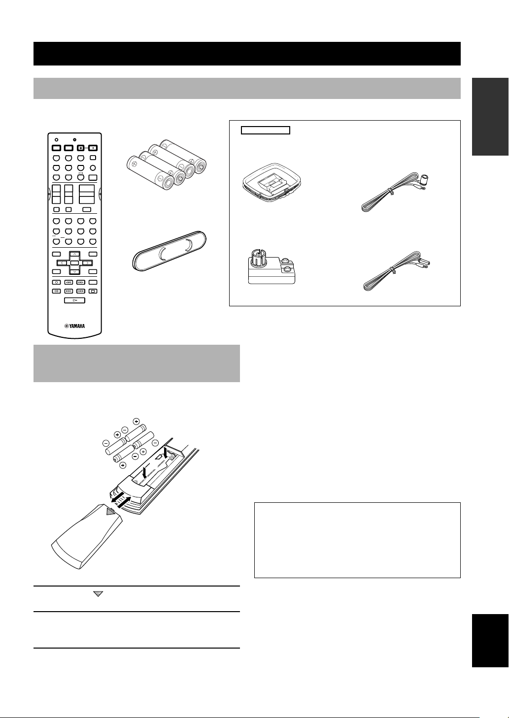
Checking the package contents
Check your package to make sure it contains the following items.
+
Batteries (4)
(AAA, R03, UM-4)
Front VIDEO AUX jack cap
RX-V630RDS
AM loop antenna
75-ohm/300-ohm antenna
adapter (U.K. model)
Remote control
CODE SET
TRANSMIT
SYSTEM
STANDBY
POWER POWER
DVD
VCR 1 VCR2/DVR
+
–
HALL
TV
SPORTS
5
/DTS
SUR.
90
LEVEL
TITLE
–
TEST
RETURN
REC
DISC SKIP
POWER
AVTV
SLEEP
MD/CD-R TUNERCD
D-TV/CBL
V-AUX
6CH INPUT
A
+
VOLUME
TV CHTV VOL
–+–
TV INPUTTV MUTE
MUTE
ENTER-
ROCK
JAZZ CLUB
CONCERT
TAINMENT
3421
MOVIE
MONO
MOVIE
THEATER 2
MOVIE
THEATER 1
678
STEREO
EX/ES
SELECT
+10
EFFECT
PRESET/CH
SET MENU
MENU
A/B/C/D/E
SELECT
DISPLAY
AUDIO
AMP
ENTER
INTRODUCTION PREPARATION
Indoor FM antenna
(U.S.A., Canada, China,
Korea and General models)
(Europe, U.K., Australia and
Singapore models)
BASIC OPERA-
TION
Installing batteries in the remote control
Insert the batteries in the correct direction by aligning the
+ and – marks on the batteries with the polarity markings
(+ and –) inside the battery compartment.
2
1
3
1 Press the part and slide off the battery
compartment cover.
2 Insert the four supplied batteries (AAA, R03,
UM-4) according to the polarity markings on
the inside of the battery compartment.
3 Slide the cover back on so that it snaps into
place.
■ Notes on batteries
• Change all of the batteries if you notice a decrease in
the operating range of the remote control, that the
indicator does not flash, or the light becoming dim.
• Do not use old batteries together with new ones.
• Do not use different types of batteries (such as alkaline
and manganese batteries) together. Read the packaging
carefully as these different types of batteries may have
the same shape and color.
• If the batteries have leaked, dispose of them
immediately. Avoid touching the leaked material or
letting it come into contact with clothing, etc. Clean
the battery compartment thoroughly before installing
new batteries.
If the remote control is without batteries for more than
2 minutes, or if exhausted batteries remain in the
remote control, the contents of the memory may be
cleared. When the memory is cleared, insert new
batteries, set up the manufacturer code that may have
been cleared.
OPERATION
ADVANCED
INFORMATION
ADDITIONAL
APPENDIX
English
3
Page 6
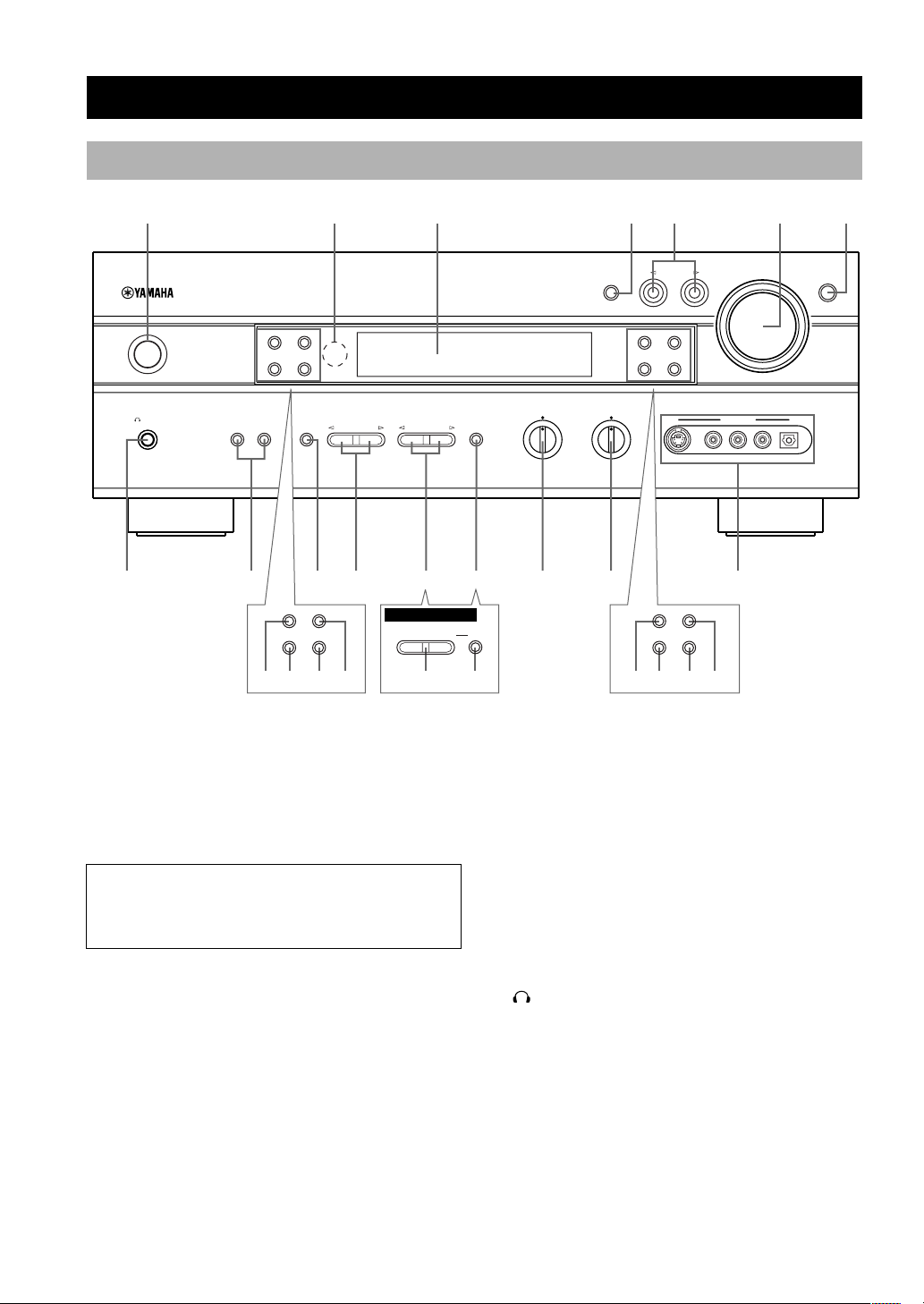
Front panel
CONTROLS AND FUNCTIONS
123 456
STANDBY
SILENT
PHONES
/
ON
NATURAL SOUND AV RECEIVER
RDS MODE/FREQ
SPEAKERS
AB
INPUT M0DE
EON
PTY SEEK
MODE
START
STEREO
EFFECT
PROGRAM
PRESET/TUNING
A/B/C/D/E
BASS
– + – +
TREBLE
INPUT
PRESET/TUNING
FM/AM
EDIT
TUNING MODE
MEMORY
AUTO/MAN'L MONO
MAN'L/AUTO FM
S VIDEO VIDEO AUDIO OPTICALLR
VOLUME
VIDEO AUX
7
6CH INPUT
(RX-V630RDS)
90 ert8qw y
RDS MODE/FREQ
EON
PTY SEEK
MODE
START
DSP-AX630SE
–
SET MENU
+
iu po w e
NEXT
PRESET/TUNING
EDIT
TUNING MODE
AUTO/MAN'L MONO
sa fd
FM/AM
MEMORY
MAN'L/AUTO FM
1 STANDBY/ON
Turns this unit on, or set it to the standby mode. When
you turn this unit on, you will hear a click and there will
be a 4 to 5-second delay before this unit can reproduce
sound.
Standby mode
In this mode, this unit will consume a small amount of
power in order to receive infrared-signals from the
remote control.
2 Remote control sensor
Receives signals from the remote control.
3 Front panel display
Shows information about the operational status of this
unit.
4 INPUT MODE
Sets the priority for the types of input signals (AUTO,
DTS, ANALOG) to receive when one component is
connected to two or more input jacks. Priority cannot be
set when 6CH INPUT is selected as the input source.
4
5 INPUT l / h
Selects the input source you want to listen to or watch.
6 VOLUME
Controls the output level of all audio channels.
This does not affect the OUT (REC) level.
7 6CH INPUT
Selects the audio source connected to the 6CH INPUT
jacks. This audio takes priority over the source selected
with INPUT l / h (or the input selector buttons on the
remote control).
8 SILENT (PHONES jack)
Allows you enjoy DSP effect for private listening with
headphones. When you connect headphones, no signals
are output to the speakers or the OUTPUT jacks.
9 SPEAKERS A/B
Turns the set of main speakers connected to the A and/or
B terminals on or off.
Page 7
CONTROLS AND FUNCTIONS
0 STEREO/EFFECT
Switches between normal stereo and DSP effect
reproduction. When STEREO is selected, 2-channel
signals are directed to the main left and right speakers
without effect sounds and all Dolby Digital and DTS
signals (except the LFE channel) are mixed down to the
main left and right speakers.
q PROGRAM l / h
Selects the DSP program.
RX-V630RDS
w
PRESET/TUNING l / h
Selects preset station numbers 1 to 8 when the colon (:)
appears in the front panel display.
Selects the tuning frequency when the colon (:) does not
appear.
DSP-AX630SE
SET MENU –/+
Adjusts the setting on the SET MENU.
RX-V630RDS
e
A/B/C/D/E
Selects preset station groups A to E.
DSP-AX630SE
NEXT
Selects the SET MENU mode.
r BASS
Adjusts the low-frequency response for the main left and
right channels.
Turn right to increase or turn left to decrease the lowfrequency response.
t TREBLE
Adjusts the high-frequency response for the main left and
right channels.
Turn right to increase or turn left to decrease the highfrequency response.
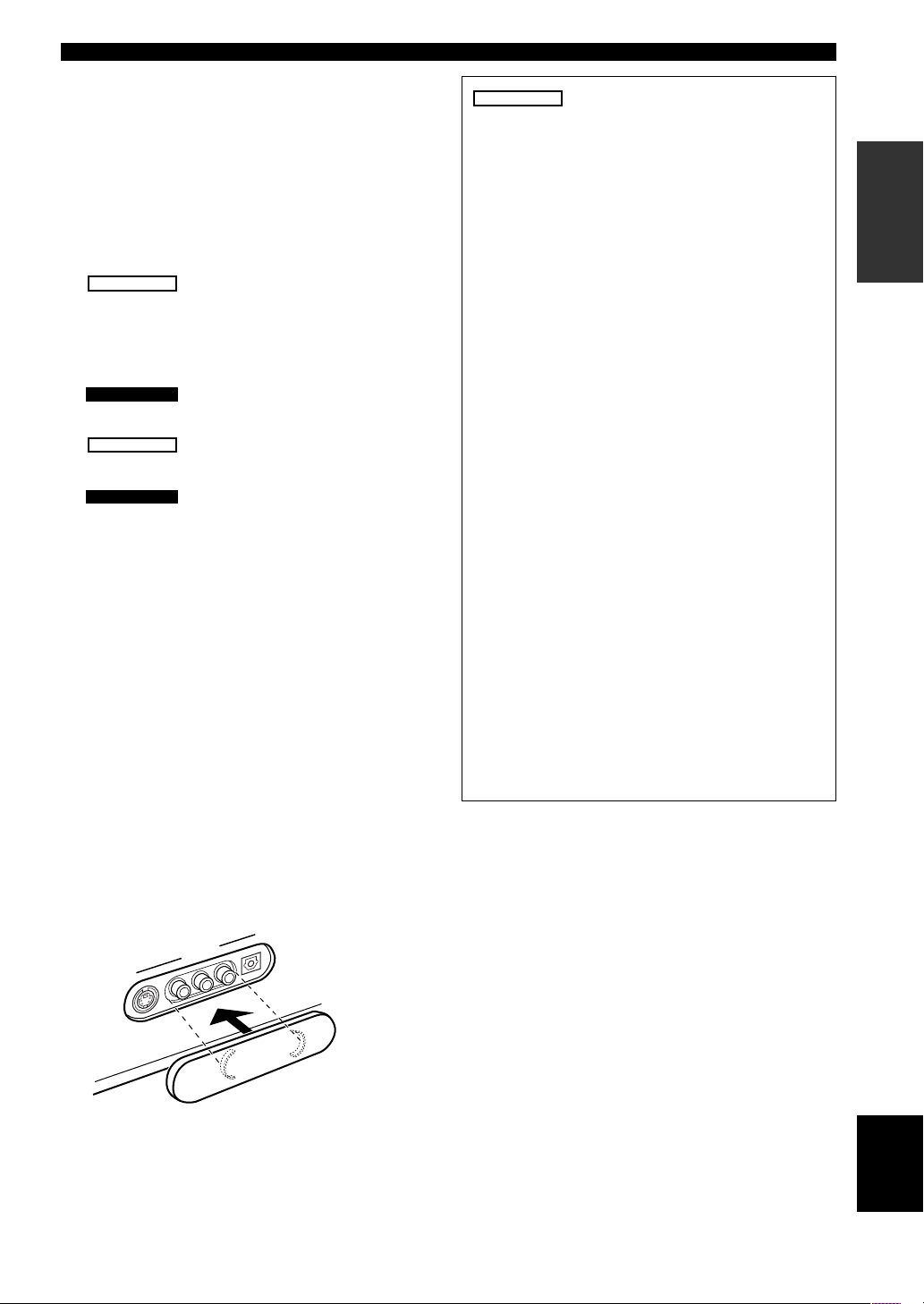
y VIDEO AUX jacks
Inputs for audio and video signals from a portable
external source (game console, etc.). Set the input source
to V-AUX to enjoy source signals from these jacks.
When the VIDEO AUX jacks on the front panel are not
used, you can attach the provided front VIDEO AUX jack
cap as shown in the illustration. When the cap is not
attached, be sure retain it carefully.
RX-V630RDS
u RDS MODE/FREQ
When an RDS station is received, press this button to
change the display mode among the PS mode, PTY
mode, RT mode, CT mode (if the station offers those
RDS data service) and/or frequency display mode in
turn.
i PTY SEEK MODE
Press this button to set the unit in the PTY SEEK
mode.
o PTY SEEK START
Press this button to begin searching for a station after
the desired program type has been selected in the PTY
SEEK mode.
p EON
Press this button to select the desired program type
(NEWS, INFO, AFFAIRS, SPORT) when you want to
tune in to a radio program of that type automatically.
a PRESET/TUNING (EDIT)
Switches the function of PRESET/TUNING l / h
between selecting a preset station number and tuning
(the colon (:) turns on or off).
This button is also used to exchange the assignment of
two preset stations with each other.
s TUNING MODE (AUTO/MAN’L MONO)
Switches the tuning mode between automatic and
manual.
d MEMORY (MAN’L/AUTO FM)
Stores the current station in the memory.
f FM/AM
Switches the reception band between FM and AM.
INTRODUCTION PREPARATION
BASIC OPERA-
TION
OPERATION
ADVANCED
INFORMATION
ADDITIONAL
X
U
A
EO
ID
V
OPTICAL
R
IO
D
U
A
L
EO
VID
EO
S VID
APPENDIX
English
5
Page 8
CONTROLS AND FUNCTIONS
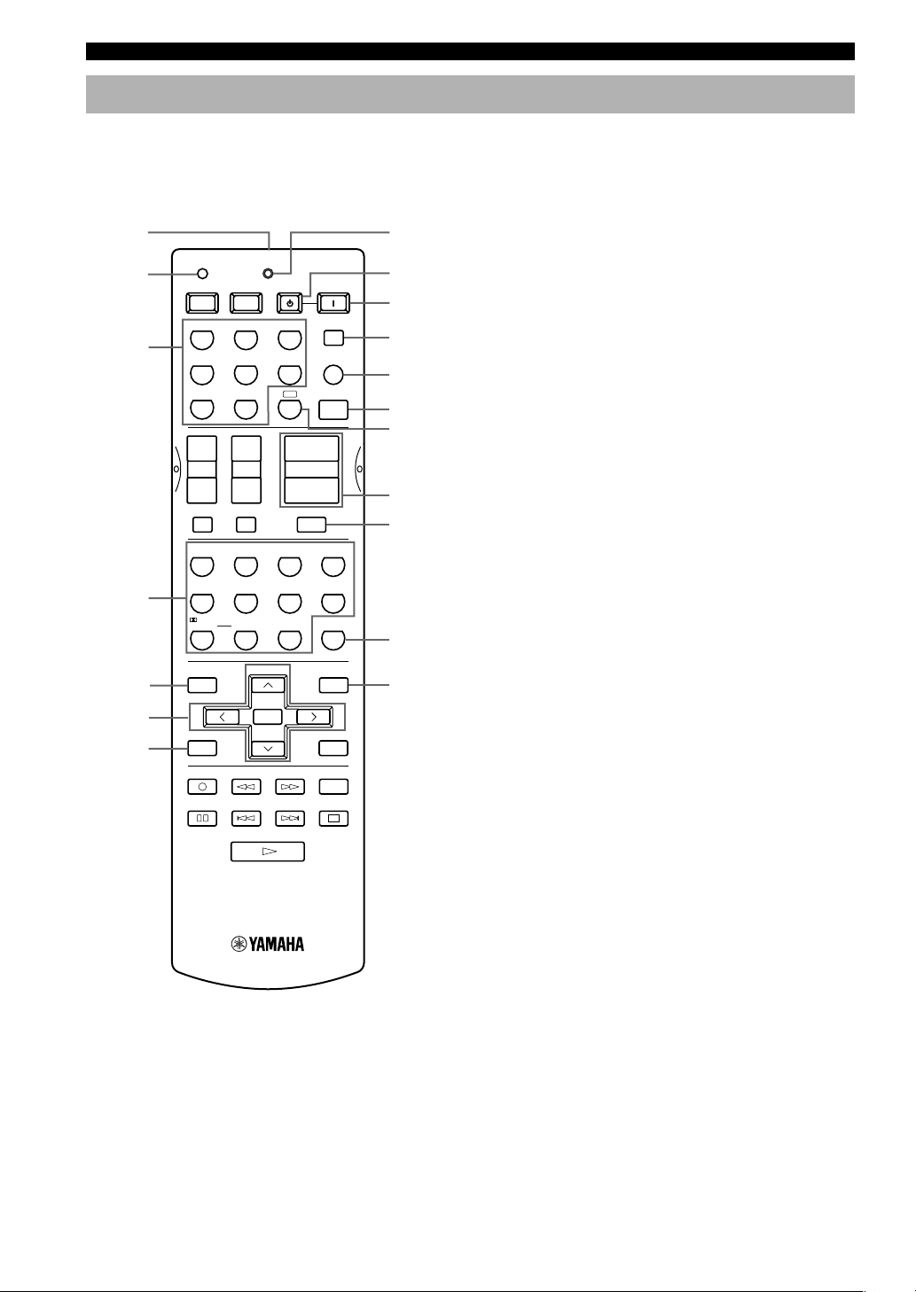
Remote control
This section describes the remote control controls and
their functions. Make sure that the AMP mode is selected
before starting operation. See “REMOTE CONTROL
FEATURES” on pages 48 to 50.
1
2
3
CODE SET
POWER POWER
AVTV
MD/CD-R TUNERCD
D-TV/CBL
DVD
TRANSMIT
STANDBY
V-AUX
SYSTEM
POWER
SLEEP
6CH INPUT
8
9
0
q
w
A
VCR 1 VCR2/DVR
AMP
e
r
SELECT
VOLUME
ROCK
CONCERT
3421
MOVIE
THEATER 1
EX/ES
+10
+
–
MUTE
THEATER 2
ENTER-
TAINMENT
MOVIE
STEREO
ENTER
EFFECT
SET MENU
MENU
A/B/C/D/E
+
DISPLAY
AUDIO
t
y
u
i
4
5
6
7
+
+
TV CHTV VOL
–
–
TV MUTE
TV INPUT
HALL
JAZZ CLUB
TV
MONO
SPORTS
MOVIE
678
5
/DTS
SUR.
SELECT
90
LEVEL
TITLE
PRESET/CH
–
TEST
RETURN
REC
DISC SKIP
1 Infrared window
Outputs infrared control signals. Aim this window at the
component you want to operate.
2 CODE SET
Used when setting up the manufacturer code (see page
49).
3 Input selector buttons
Select the input source and set the remote control to
operate the selected source component.
4 DSP program
Select DSP programs for the AMP position. Press a
button repeatedly to select a DSP program within that
group.
5 LEVEL
Selects the effect speaker channel to be adjusted.
6 Multi control section
Used when changing the setting and to implement the
settings.
7 TEST
Outputs the test tone to adjust the speaker levels.
8 TRANSMIT indicator
Flashes while the remote control is sending signals.
9 STANDBY
Sets this unit in the standby mode.
0 SYSTEM POWER
Turns on the power of this unit.
q SLEEP
Sets the sleep timer.
w 6CH INPUT
Selects the audio source connected to the 6CH INPUT
jacks.
e AMP
Sets the remote control to the AMP mode for controlling
this unit.
r Å
Sets the remote control to operate other component (not
necessarily connected to this unit) without changing this
unit’s input source.
t VOLUME +/–
Increases or decreases the volume level.
y MUTE
Mutes the sound. Press again to restore the audio output
to the previous volume level.
6
Page 9
CONTROLS AND FUNCTIONS
VCR 1 VCR2/DVR
NATURAL SOUND AV RECEIVER
SPEAKERS
AB
SILENT
PHONES
STANDBY
/
ON
STEREO
EFFECT
PROGRAM
PRESET/TUNING
A/B/C/D/E
BASS
– + – +
TREBLE
VIDEO AUX
S VIDEO VIDEO AUDIO OPTICALLR
MEMORY
FM/AM
EDIT
PRESET/TUNING
MAN'L/AUTO FMAUTO/MAN'L MONO
TUNING MODE
VOLUMEINPUT
INPUT M0DE
6CH INPUT
30° 30°
u STEREO/EFFECT
Switches between normal stereo and DSP effect
reproduction. When STEREO is selected, 2-channel
signals are directed to the main left and right speakers
without effect sounds and all Dolby Digital and DTS
signals (except the LFE channel) are mixed down to the
main left and right speakers.
i SET MENU
Selects the SET MENU mode.
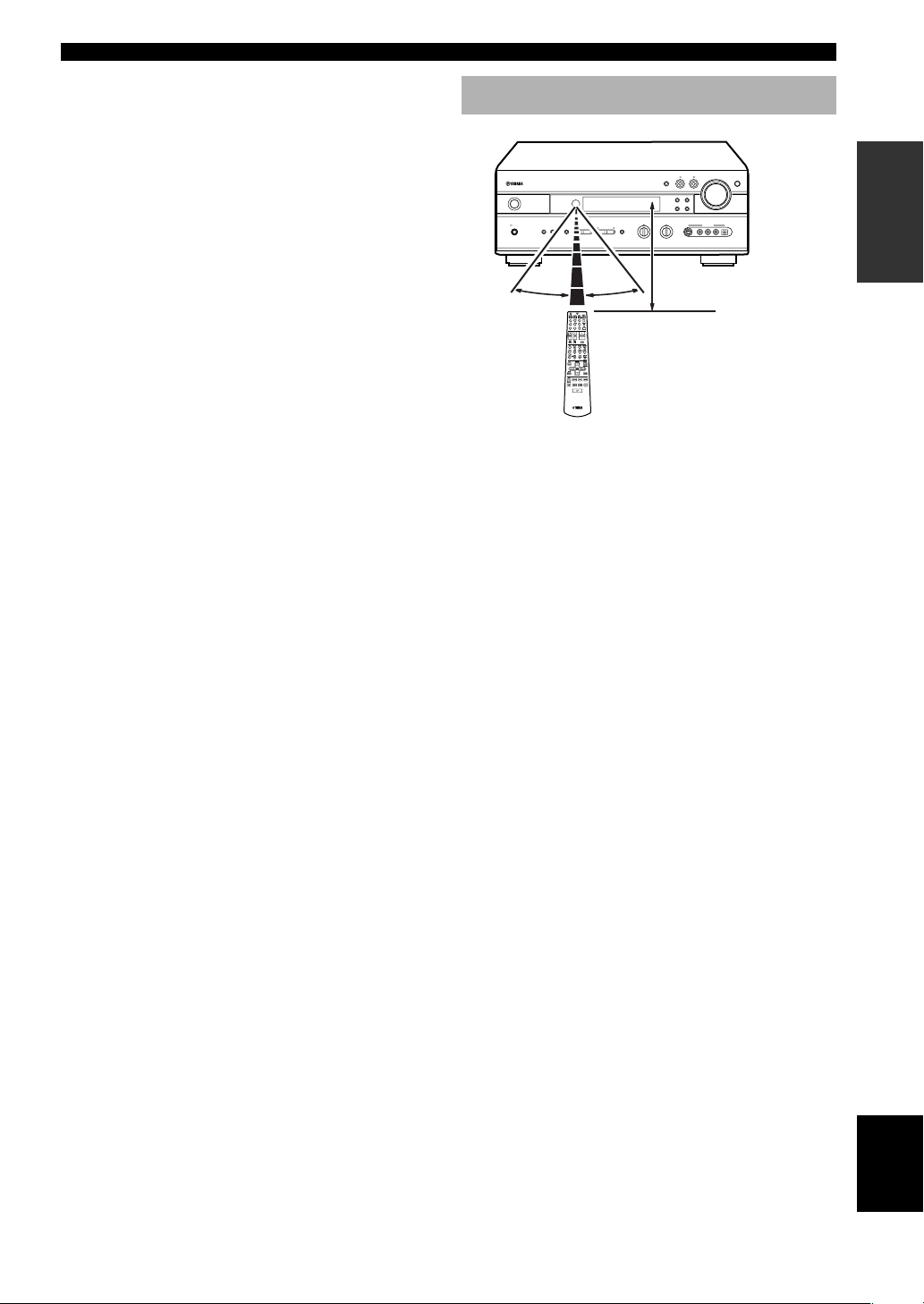
Using the remote control
Approximately 6 m (20 feet)
The remote control transmits a directional infrared beam.
Be sure to aim the remote control directly at the remote
control sensor on the main unit during operation.
■ Handling the remote control
• Do not spill water or other liquids on the remote
control.
• Do not drop the remote control.
• Do not leave or store the remote control in the
following types of conditions:
– high humidity or temperature such as near a heater,
stove or bath;
– dusty places; or
– in places subject to extremely low temperatures.
INTRODUCTION PREPARATION
BASIC OPERA-
TION
OPERATION
ADVANCED
INFORMATION
ADDITIONAL
APPENDIX
English
7
Page 10
CONTROLS AND FUNCTIONS
RX-V630RDS
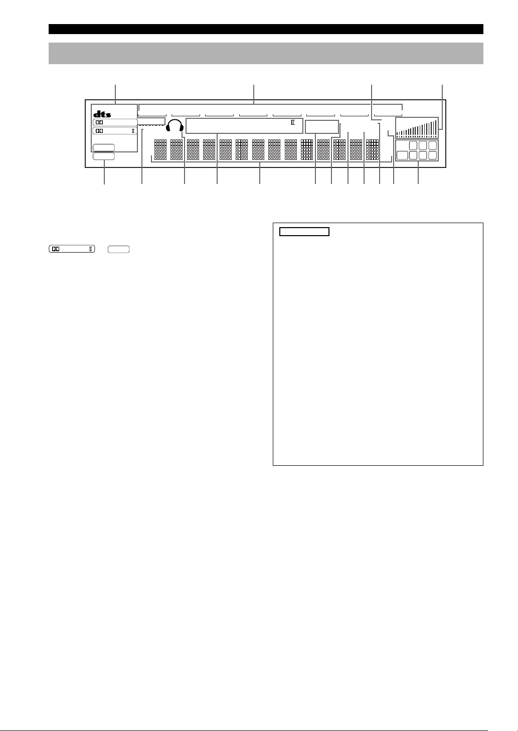
Front panel display
1234
MATRIX
VCR2/DVR
/
VIRTUAL
SILENT
6
DIGITAL
PRO LOGIC
DSP
PCM
57890qwert y
VCR
1
DTS
MOVIE
V-AUX
D-TV/CBL
DOLBY DIGITAL PRO LOGIC
THTR
12
ENTERTAINMENT
1 Processor indicators
Lights up when the t, g, VIRTUAL,
MATRIX lights up when the Dolby Digital EX decoder or
the DTS-ES compatible decoder is activated.
PRO LOGIC
/
DSP
or
are activated.
2 Input source indicator
Shows the current input source with a cursor.
3 MUTE indicator
Flashes while the MUTE function is on.
4 VOLUME level indicator
Indicates the volume level.
5 v indicator
Lights up when this unit is reproducing PCM (pulse code
modulation) digital audio signals.
6 SILENT indicator
Lights up when headphones are connected while the
digital sound field processor is on.
7 Headphones indicator
Lights up when headphones are connected.
8 DSP program indicators
The name of the selected DSP program lights up when the
ENTERTAINMENT, MOVIE THEATER 1, MOVIE
THEATER 2 or V/DTS SURROUND DSP program is
selected.
DVD
MD/CD-R
PS PTY
EON
RT
CT
PTY HOLD
TUNER CD
STEREO
TUNED
AUTO
MEMORY
MUTE
SLEEP
dB
mS
VOLUME
LCR
RL
RC RR
LFE
(RX-V630RDS)
0 RDS indicator
The name(s) of the RDS data offered by the currently
received RDS station light(s) up.
EON indicator lights up when an RDS station that
offers the EON data service is being received.
PTY HOLD indicator lights up while searching for
stations in the PTY SEEK mode.
q STEREO indicator
Lights up when this unit is receiving a strong signal
for an FM stereo broadcast while the “AUTO”
indicator is lit.
w TUNED indicator
Lights up when this unit is tuned to a station.
e MEMORY indicator
Flashes to show a station can be stored.
r AUTO indicator
Shows that this unit is in the automatic tuning mode.
t SLEEP indicator
Lights up while the sleep timer is on.
y Input channel indicator
Indicates the channel components of input signals being
received.
9 Multi-information display
Shows the current DSP program name and other
information when adjusting or changing settings.
8
Page 11
PREPARATION
Speakers
SPEAKER SETUP
INTRODUCTION
Speaker placement
This unit has been designed to provide the best soundfield quality with a 6-speaker system, using main left and
right speakers, rear left and right speakers, a center
speaker, and a rear center speaker. If you use different
brands of speakers (with different tonal qualities) in your
system, the tone of a moving human voice and other types
of sound may not shift smoothly. We recommend that you
use speakers from the same manufacturer or speakers
with the same tonal quality.
The main speakers are used for the main source sound
plus effect sounds. They will probably be the speakers
from your present stereo system. The rear speakers are
used for effect and surround sounds. The center speaker is
for the center sounds (dialog, vocals, etc.). The rear center
speaker supplements the rear (left and right) speakers and
provides for more realistic front-to-back transitions.
The main speakers should be high-performance models
and have enough power-handling capacity to accept the
maximum output of your audio system. The other
speakers do not have to be equal to the main speakers. For
precise sound localization, however, it is ideal to use the
models of equivalent performance with the main
speakers.
■ Use of a subwoofer expands your
sound field
It is also possible to further expand your system with the
addition of a subwoofer. The use of a subwoofer is
effective not only for reinforcing bass frequencies from
any or all channels, but also for reproducing the LFE
(low-frequency effect) channel with high fidelity when
playing back Dolby Digital or DTS signals. The
YAMAHA Active Servo Processing Subwoofer System is
ideal for natural and lively bass reproduction.
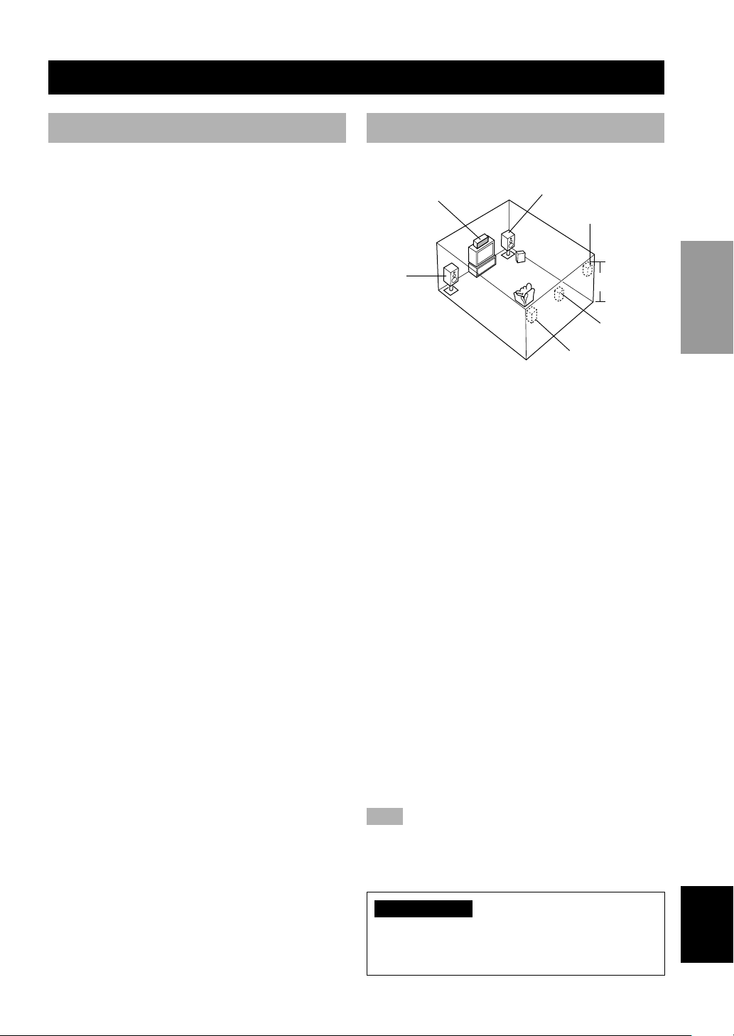
Refer to the following diagram when you place the
speakers.
Main speaker (R)Center speaker
Rear speaker (R)
Subwoofer
Main
speaker (L)
1.8 m (6 feet)
Rear center
speaker
Rear speaker (L)
■ Main speakers
Place the main left and right speakers an equal distance
from the ideal listening position. The distance between
each speaker and each side of the video monitor should
also be the same.
■ Center speaker
Align the front face of the center speaker with the front
face of your video monitor. Place the speaker as close to
the monitor as possible (such as directly over or under the
monitor) and centrally between the main speakers.
■ Rear speakers
Place these speakers behind your listening position,
facing slightly inwards, nearly 1.8 m (6 feet) above the
floor.
■ Rear center speaker
Place the rear center speaker in the center between the
rear left and right speakers at the same height from the
floor as the rear speakers.
■ Subwoofer
The position of the subwoofer is not so critical, because
low bass sounds are not highly directional. But it is better
to place the subwoofer near the main speakers. Turn it
slightly toward the center of the room to reduce wall
reflections.
Note
• If you do not use any of effect speakers (rear, center and/or rear
center), change the settings of SPEAKER SET items at the
SET MENU to designate the signals to other terminals you
connect speakers to.
CAUTION
Use magnetically shielded speakers. If this type of
speakers still creates the interference with the monitor,
place the speakers away from the monitor.
PREPARATION
BASIC OPERA-
TION
OPERATION
ADVANCED
INFORMATION
ADDITIONAL
APPENDIX
English
9
Page 12
SPEAKER SETUP
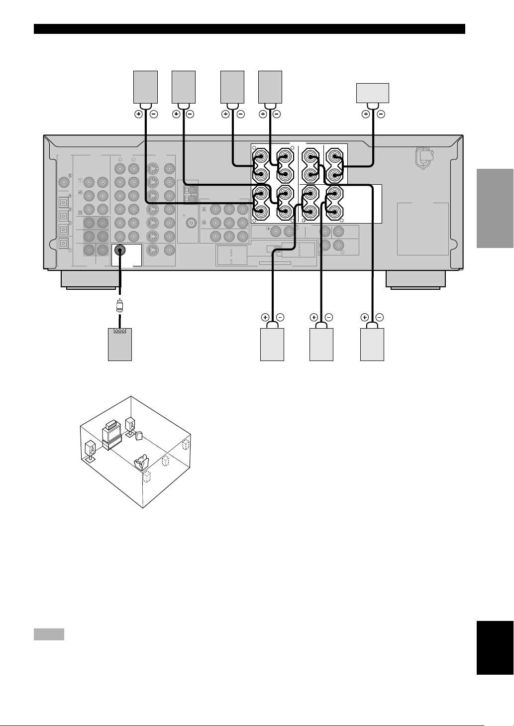
Connecting the speakers
Be sure to connect the left channel (L), right channel (R), “+” (red) and “–” (black) properly. If the connections are
faulty, no sound will be heard from the speakers, and if the polarity of the speaker connections is incorrect, the sound
will be unnatural and lack bass.
CAUTION
• Use speakers with the specified impedance shown on the rear panel of this unit.
• Do not let the bare speaker wires touch each other or any metal part of this unit. This could damage this unit
and/or the speakers.
If necessary, use the SET MENU to change the speaker mode settings according to the number and size of the speakers
in your configuration after you finish connecting your speakers.
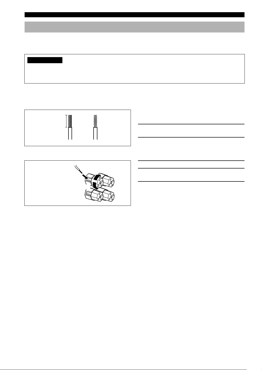
■ Speaker cables
A speaker cord is actually a pair of insulated cables
running side by side. One cable is colored or shaped
10 mm (3/8”)
differently, perhaps with a stripe, groove or ridge.
1 Remove approximately 10 mm (3/8”) of
12
insulation from each of the speaker cables.
2 Twist the exposed wires of the cable
together to prevent short circuits.
■ Connecting to the SPEAKERS terminals
Red: positive (+)
Black: negative (–)
2
3
1
1 Unscrew the knob.
2 Insert one bare wire into the hole in the side
of each terminal.
3 Tighten the knob to secure the wire.
■ MAIN SPEAKERS terminals
One or two speaker systems can be connected to these terminals. When using only one speaker system, it can be
connected to either the MAIN A or the MAIN B terminals.
■ REAR SPEAKERS terminals
A rear speaker system can be connected to these terminals.
■ CENTER SPEAKER terminals
A center speaker can be connected to these terminals.
■ REAR CENTER SPEAKER terminals
A rear center speaker can be connected to these terminals.
10
Page 13
SPEAKER SETUP
DIGITAL
INPUT
CD
CD
COAXIAL
OPTICAL
D-TV/CBL
OUT
(REC)
MD
/CD-R
IN
DVD
(PLAY)
MD/CD-R
MAIN
SURROUND
MD/CD-R
OPTICAL
WOOFER
DIGITAL
OUTPUT
(RX-V630RDS)
SUB
6CH INPUT
CENTER
Main B speaker
Right Left
AUDIOAUDIO
L
R
S VIDEO VIDEO
OUT
VCR 2
/VDR
IN
OUT
VCR 1
IN
D-TV
/CBL
DVD
SUB
WOOFER
S VIDEO
OUTPUT
VIDEO
MONITOR OUT
VIDEO
Main A speaker
Right Left
1
R
TUNER
AM
ANT
GND
75
FM
ANT
COMPONENT VIDEO
DVD
UNBAL.
D-TV
/CBL
MONITOR
OUT
B/CBPR/CR
MAIN
:4
A OR B
:8
A+B
:6
CENTER
REAR CENTER
:6
:6
REAR
YP
MIN. /SPEAKER
MIN. /SPEAKER
MIN. /SPEAKER
MIN. /SPEAKER
MIN. /SPEAKER
R
MAIN
R
MAIN
MAIN A OR B
CENTER
REAR CENTER
REAR
SET BEFORE POWER ON
IMPEDANCE SELECTOR
2
SPEAKERS
L
+
A
–
–
B
+
L
L
:
8
:
16
A+B
:
8
:
8
:
8
REAR CENTER
R
OUTPUT
REAR
CENTER
MIN. /SPEAKER
MIN. /SPEAKER
MIN. /SPEAKER
MIN. /SPEAKER
MIN. /SPEAKER
+
–
REAR
(SURROUND)
R
CENTER
REAR
(SURROUND)
L
L
3
+
–
–
+
CENTER
Center
speaker
INTRODUCTION
PREPARATION
AC OUTLETS
BASIC OPERA-
TION
4
Subwoofer
system
3
56
Right
Left
Rear speaker
1
7
Rear center
speaker
4
2
5
7
6
The diagram shows the speaker layout in the listening
room.
■ SUBWOOFER jack
When using a subwoofer with built-in amplifier, including the YAMAHA Active Servo Processing Subwoofer System,
connect the input jack of the subwoofer system to this jack. Low bass signals distributed from the main, center and/or
rear channels are directed to this jack in accordance with your SPEAKER SET selections. The LFE (low-frequency
effect) signals generated when Dolby Digital or DTS is decoded are also directed to this jack in accordance with your
SPEAKER SET selections.
Notes
• The cut-off frequency of the SUBWOOFER jack is 90 Hz.
• If you do not use a subwoofer, designate the signals to the main left and right speakers by changing the setting of SPEAKER SET
item “1E BASS” on the SET MENU to MAIN.
• Use the control on the subwoofer to adjust its volume level. It is also possible to adjust the volume level by using this unit’s remote
control (see “ADJUSTING THE LEVEL OF THE EFFECT SPEAKERS” on page 51).
OPERATION
ADVANCED
INFORMATION
ADDITIONAL
APPENDIX
English
11
Page 14
SPEAKER SETUP
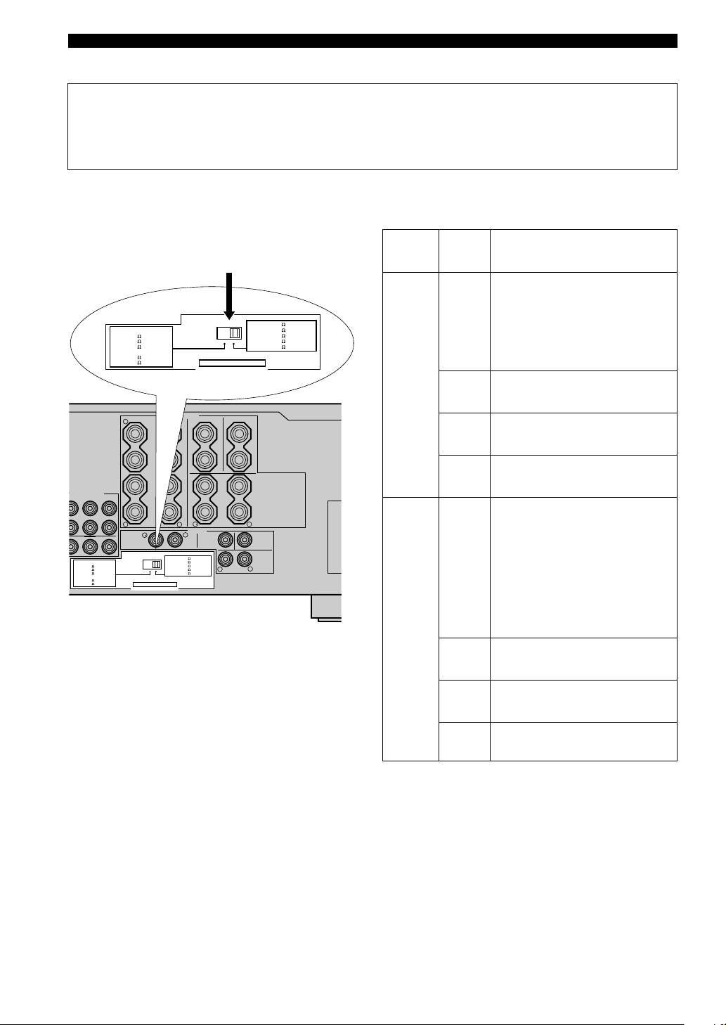
■ IMPEDANCE SELECTOR switch
WARNING
Do not change setting of the IMPEDANCE SELECTOR switch when the power of this unit is on, this may damage
the unit. If this unit fails to turn on when STANDBY/ON (or SYSTEM POWER) is pressed, the IMPEDANCE
SELECTOR switch may not be fully slid to either position. If so, slide the switch all the way to either position when
this unit is in the standby mode.
Select the switch position (left or right) according to the impedance of the speakers in your system. Be sure to move this
switch only when this unit is in the standby mode.
MAIN
A OR B
A+B
CENTER
REAR CENTER
REAR
R
MPONENT VIDEO
B/CB/CR
YP
R
MAIN
:4
MIN. /SPEAKER
A OR B
:8
MIN. /SPEAKER
A+B
:6
MIN. /SPEAKER
CENTER
REAR CENTER
:6
MIN. /SPEAKER
:6
MIN. /SPEAKER
REAR
(RX-V630RDS)
:4
MIN. /SPEAKER
:8
MIN. /SPEAKER
:6
MIN. /SPEAKER
:6
MIN. /SPEAKER
:6
MIN. /SPEAKER
MAIN
R
MAIN
SET BEFORE POWER ON
IMPEDANCE SELECTOR
SPEAKERS
L
+
A
–
–
B
+
L
:
MAIN A OR B
:
A+B
16
:
CENTER
:
REAR CENTER
:
REAR
REAR CENTER
OUTPUT
L
MIN. /SPEAKER
8
MIN. /SPEAKER
MIN. /SPEAKER
8
MIN. /SPEAKER
8
MIN. /SPEAKER
8
IMPEDANCE
SELECTOR
switch
SET BEFORE POWER ON
IMPEDANCE SELECTOR
CENTER
+
–
REAR
R
(SURROUND)
REAR
CENTER
REAR
R
(SURROUND)
:
MAIN A OR B
:
A+B
16
:
CENTER
:
REAR CENTER
:
REAR
+
–
–
+
L
CENTER
L
MIN. /SPEAKER
8
MIN. /SPEAKER
MIN. /SPEAKER
8
MIN. /SPEAKER
8
MIN. /SPEAKER
8
Switch
position
Left
Right
Speaker
Main
Center
Rear
Center
Rear
Main
Impedance level
If you use one set of main speakers,
the impedance of each speaker must
be 4 Ω or higher.
If you use two sets of main speakers,
the impedance of each speaker must
be 8 Ω or higher.
The impedance must be 6 Ω or
higher.
The impedance must be 6 Ω or
higher.
The impedance of each speaker must
be 6 Ω or higher.
If you use one set of main speakers,
the impedance of each speaker must
be 8 Ω or higher.
If you use two sets of main speakers,
the impedance of each speaker must
be 16 Ω or higher.
[Canada model only]
The impedance of each speaker must
be 8 Ω or higher.
12
Center
Rear
Center
Rear
The impedance must be 8 Ω or
higher.
The impedance must be 8 Ω or
higher.
The impedance of each speaker must
be 8 Ω or higher.
Page 15
CONNECTIONS
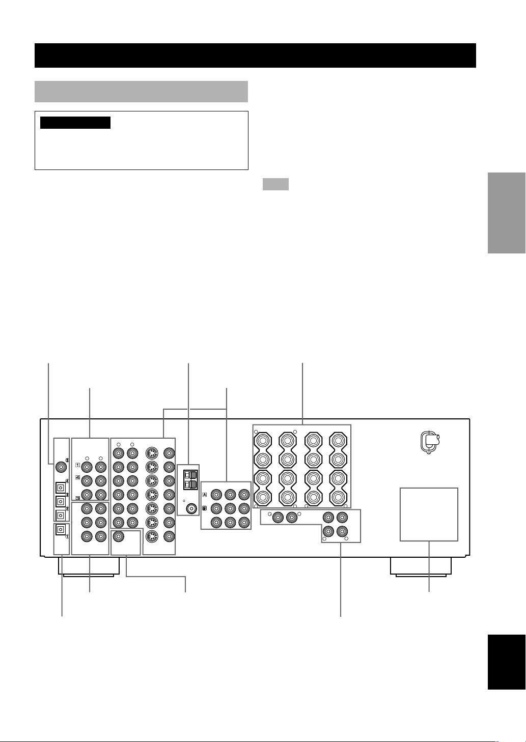
Before connecting components
CAUTION
Do not connect this unit or other components to the
mains power until all connections between the
components have been completed.
• Be sure all connections are made correctly, that is to
say L (left) to L, R (right) to R, “+” to “+” and “–” to
“–”. Some components require different connection
methods and have different jack names. Refer to the
operation instructions for each component to be
connected to this unit.
• When you connect other YAMAHA audio components
(such as a tape deck, MD recorder and CD player or
changer), connect them to the jack with the same
number labels as !, #, $ etc. YAMAHA applies this
labeling system to all its products.
• After you have completed all connections, check them
again to make sure they are correct.
• The name of jack corresponds to input selector.
DIGITAL INPUT jacks
(pages 13-16)
Audio component jacks
(page 16)
Antenna input terminals
(page 17)
Video component jacks
(pages 14-15)
■ Connecting to digital jacks
This unit has digital jacks for direct transmission of
digital signals through either coaxial or fiber optic cables.
You can use the digital jacks to input PCM, Dolby Digital
and DTS bitstreams. To enjoy multi-channel sound track
of DVD software, etc. with DSP effect, you need to make
digital connection. All digital input jacks are acceptable
for 96-kHz sampling digital signals.
Note
• The OPTICAL jacks on this unit conform to the EIA standard.
If you use a fiber optic cable that does not conform to this
standard, this unit may not function properly.
Speaker terminals
(pages 10-11)
INTRODUCTION
PREPARATION
BASIC OPERA-
TION
OPERATION
ADVANCED
CENTER
AUDIOAUDIO
R
L
OUTPUT
DIGITAL
INPUT
CD
COAXIAL
OPTICAL
D-TV/CBL
DVD
MD/CD-R
MD/CD-R
OPTICAL
DIGITAL
OUTPUT
CD
OUT
(REC)
MD
/CD-R
(PLAY)
MAIN
SURROUND
IN
SUB
WOOFER
R
6CH INPUT
6CH INPUT jacks
(page 18)
DIGITAL OUTPUT jack
(page 16)
VIDEO
L
S VIDEO VIDEO
OUT
VCR 2
/VDR
SUB
WOOFER
VCR 1
IN
OUT
IN
D-TV
/CBL
DVD
S VIDEO
MONITOR OUT
VIDEO
AM
ANT
GND
ANT
TUNER
75
FM
SUBWOOFER OUTPUT
jack (page 11)
(RX-V630RDS)
R
COMPONENT VIDEO
B/CBPR/CR
DVD
UNBAL.
D-TV
/CBL
MONITOR
OUT
YP
R
MAIN
L
+
A
–
–
B
+
L
L
R
SPEAKERS
MAIN
REAR CENTER
R
OUTPUT
REAR
CENTER
+
–
REAR
(SURROUND)
R
CENTER
REAR
(SURROUND)
L
L
+
–
–
+
CENTER
INFORMATION
ADDITIONAL
APPENDIX
AC OUTLETS
(page 19)
OUTPUT jacks
(page 18)
English
13
Page 16

CONNECTIONS
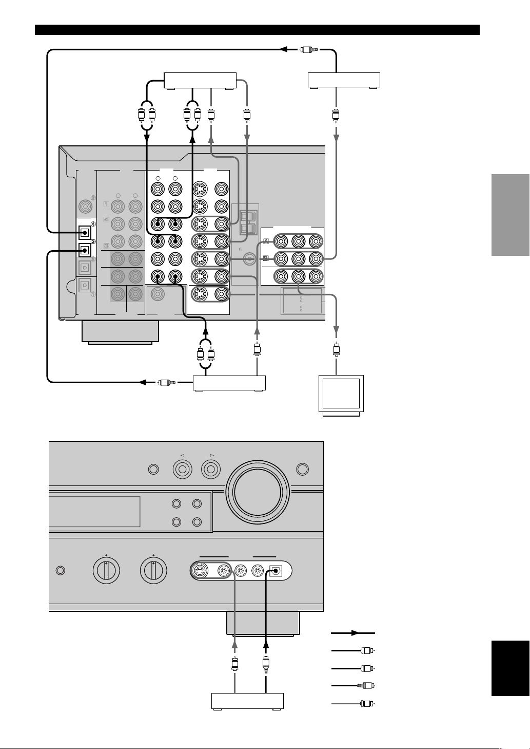
Connecting video components
Refer to the connection examples on the next page.
■ Types of video jacks
There are three types of video jacks as follows:
VIDEOS VIDEO
2 1 3
1 VIDEO jack
Conventional composite video signal.
2 S VIDEO jack
Transmits color and luminance separately and achives
high-quality color reproduction.
3 COMPONENT VIDEO jacks
Transmit color difference (PB/CB, PR/CR) and luminance
separately and provide the best quality picture.
• Each type of video jack works independently. Signals
input through the composite video, S-video and
component jacks are only output through the
corresponding composite video, S-video, and
component jacks.
• Use a commercially available cable specified for
connecting each type of jacks.
The description of the component video jacks may differ
•
depending on the component (e.g. Y, C
B-Y, R-Y etc.). When using these jacks, refer also to the
operation instructions for the component being connected.
■ Connecting a video monitor
Connect the video input jack on your video monitor to the
MONITOR OUT VIDEO jack.
Note
• If you connect this unit with a source component using S-video
(or Component video) jacks, you also need to connect your
video monitor using S-video (or Component video) jacks.
■ Connecting a DVD player/digital
TV/cable TV
Connect the optical digital audio signal output jack on
your component to the DIGITAL INPUT jack and
connect the video signal output jack on the component to
the VIDEO jack on this unit.
Then connect AUDIO jacks on your component to the
AUDIO jacks on this unit.
COMPONENT VIDEO
P
R/CRPB/CB
Y
, CR/Y, PB, PR/Y,
B
y
• If your video component has an S-video output or component
video output, connect the S-video signal output jack on the
component to the S VIDEO jack or connect the component
video signal output jacks on the component to the
COMPONENT VIDEO jacks.
• The AUDIO jacks are available for a video component which
does not have optical digital output jack. However, multichannel reproduction cannot be obtained with audio signals
input from AUDIO jacks.
■ Connecting a game console or
camcorder
Connect the optical digital audio signal output jack on
your video component to the OPTICAL jack on the front
panel and connect video signal output jack on the
component to the VIDEO jack on the front panel.
y
• If your video component has an S-video output, connect the Svideo signal output jack on the component to the S VIDEO
jack.
• The AUDIO jacks are available for a video component such as
a camcorder which does not have optical digital output jack.
■ Connecting a VCR or DVR (digital
video recorder)
Connect the audio signal input jacks on your video
component to the AUDIO OUT jacks and connect the
video signal input jack on the video component to the
VIDEO OUT jack on this unit for picture recording.
Connect the audio signal output jacks on your component
to the AUDIO IN jacks and connect the video signal
output jack on the component to the VIDEO IN jack on
this unit to play a source from your recording component.
Second VCR or digital video recorder can be connected
using VCR 2/DVR jacks.
y
• If your video component has an S-video input, connect the Svideo signal input jack on the component to the S VIDEO OUT
jack.
• If your video component has an S-video output, connect the Svideo signal output jack on the component to the S VIDEO IN
jack.
Notes
• Once you have connected a recording component to this unit,
keep its power turned on while using this unit. If the power is
off, this unit may distort the sound from other components.
• S-video and component video signals pass independently
through this unit’s video circuit. Make sure to connect this unit
to both a source component and a recording component using
the video jacks of the same system.
14
Page 17
CONNECTIONS
DIGITAL
INPUT
CD
COAXIAL
OPTICAL
D-TV/CBL
DVD
MD/CD-R
MD/CD-R
OPTICAL
DIGITAL
OUTPUT
CD
OUT
(REC)
MD
/CD-R
IN
(PLAY)
MAIN
SURROUND
AUDIO
OUTPUT
R
SUB
CENTER
WOOFER
6CH INPUT
VCR 1
O
OPTICAL
OUTPUT
TV/digital TV/
cable TV
INTRODUCTION
AUDIO
INPUT
R
L
AUDIOAUDIO
L
R
OUTPUT
SUB
WOOFER
OUT
VCR 2
/VDR
OUT
VCR 1
D-TV
/CBL
DVD
L
L
R
S VIDEO VIDEO
IN
IN
S VIDEO
MONITOR OUT
VIDEO
INPUT
V V
VIDEO
VIDEO
TUNER
AM
ANT
GND
FM
ANT
75
VIDEO
OUTPUT
UNBAL.
COMPONENT VIDEO
DVD
D-TV
/CBL
MONITOR
OUT
B/CBPR/CR
MAIN
:4
MIN. /SPEAKER
A OR B
:8
MIN. /SPEAKER
A+B
:6
MIN. /SPEAKER
CENTER
REAR CENTER
:6
MIN. /SPEAKER
:6
MIN. /SPEAKER
REAR
VIDEO
OUTPUT
V
PREPARATION
YP
BASIC OPERA-
TION
(RX-V630RDS)
A/B/C/D/E
(RX-V630RDS)
INPUT M0DE
BASS
– + – +
TREBLE
Game console or
camcorder
O
OPTICAL
OUTPUT
PRESET/TUNING
EDIT
TUNING MODE
AUTO/MAN'L MONO
R
L
AUDIO
OUTPUT
DVD player
INPUT
FM/AM
MEMORY
MAN'L/AUTO FM
S VIDEO VIDEO AUDIO OPTICALLR
VIDEO
OUTPUT
VOLUME
VIDEO AUX
V
V
VIDEO
OUTPUT
O
OPTICAL
OUTPUT
6CH INPUT
V
VIDEO
INPUT
Video monitor
indicates signal direction
L
indicates left analog cables
R
indicates right analog cables
O
indicates optical cables
V
indicates video cables
OPERATION
ADVANCED
INFORMATION
ADDITIONAL
APPENDIX
English
15
Page 18
CONNECTIONS
DSP-AX630SE
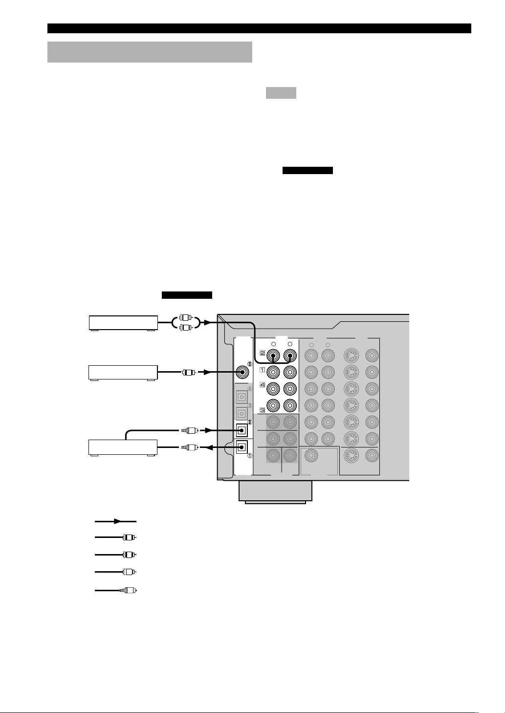
Connecting audio components
■ Connecting a CD player
Connect the coaxial digital output jack on your CD player
to the DIGITAL INPUT CD jack.
y
• The AUDIO jacks are available for a CD player which does not
have coaxial digital output jack.
■ Connecting a CD recorder or MD
recorder
Connect the optical digital signal input jack on your CD
recorder or MD recorder to the DIGITAL OUTPUT MD/
CD-R jack for digital recording.
Connect the optical digital output jack on your CD
recorder or MD recorder to the DIGITAL INPUT MD/
CD-R jack to play a source from your recording
component.
DSP-AX630SE
AUDIO
OUTPUT
L
R
Tuner
CD player
CD recorder or
MD recorder
COAXIAL
OUTPUT
OPTICAL
OUTPUT
OPTICAL
INPUT
C
O
O
DIGITAL
INPUT
CD
COAXIAL
OPTICAL
D-TV/CBL
DVD
MD/CD-R
MD/CD-R
OPTICAL
DIGITAL
OUTPUT
y
• The AUDIO jacks are available for an CD recorder or MD
recorder which does not have optical digital input or output
jack.
Notes
• Once you have connected a recording component to this unit,
keep its power turned on while using this unit. If the power is
off, this unit may distort the sound from other components.
• DIGITAL OUTPUT jack and analog OUT (REC) jacks are
independent. Only digital signals are output from DIGITAL
OUTPUT jack and analog signals from OUT (REC) jacks.
■
Connect the output jacks on your tuner to the TUNER
jacks.
AUDIO
L
R
TUNER
CD
OUT
(REC)
MD
/CD-R
IN
(PLAY)
MAIN
SURROUND
SUB
CENTER
WOOFER
6CH INPUT
Connecting a tuner
VIDEOAUDIO
L
R
OUTPUT
SUB
WOOFER
S VIDEO VIDEO
OUT
VCR 2
/VDR
IN
OUT
VCR 1
IN
D-TV
/CBL
DVD
S VIDEO
MONITOR OUT
VIDEO
16
indicates signal direction
L
indicates left analog cables
R
indicates right analog cables
C
indicates coaxial cables
O
indicates optical cables
(DSP-AX630SE)
Page 19
CONNECTIONS
T
T
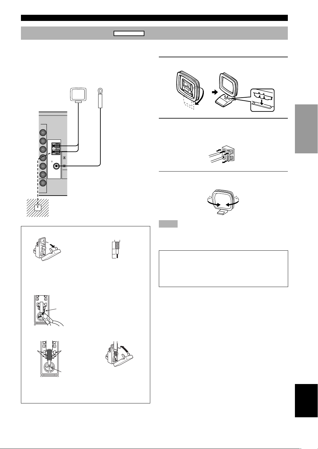
Connecting the antennas
RX-V630RDS
Both AM and FM indoor antennas are included with this
unit. In general, these antennas should provide sufficient
signal strength.
Connect each antenna correctly to the designated
terminals.
AM loop antenna
(included)
O
VIDEO
TUNER
AM
ANT
GND
75
UNBAL.
FM
ANT
VIDEO
OUT
DVD
D-TV
/CBL
MONI
OU
Ground (GND terminal)
For maximum safety and minimum
interference, connect the antenna GND
terminal to a good earth ground. A good
earth ground is a metal stake driven into
moist earth.
Indoor FM
antenna
(included)
■ Connecting the AM loop antenna
1 Set up the AM loop antenna, then connect it.
2 Press and hold the tab to insert the AM loop
antenna lead wires into the AM ANT and
GND terminals.
3 Orient the AM loop antenna for the best
reception.
INTRODUCTION
PREPARATION
BASIC OPERA-
TION
75-ohm/300-ohm antenna adapter (U.K. model)
12
11 (7/16)
Open the cover of the
included 75-ohm/300-ohm
antenna adapter.
8 (5/16)
6 (1/14)
Cut the external sleeve
of the 75-ohm coaxial
cable and prepare it for
Unit:
mm (inch)
connection.
3
Lead wire
Cut the lead wire and
remove it.
4
Clamp
with
pliers.
Insert the cable wire into the
slot, and clamp it with pliers.
Clamp with
pliers.
Insert the wire
into the slot.
5
Snap the cover into
place.
Notes
• The AM loop antenna should be placed away from this unit.
• The AM loop antenna should always be connected, even if an
outdoor AM antenna is connected to this unit.
A properly installed outdoor antenna provides clearer
reception than an indoor one. If you experience poor
reception quality, an outdoor antenna may improve the
quality. Consult the nearest authorized YAMAHA
dealer or service center about the outdoor antennas.
OPERATION
ADVANCED
INFORMATION
ADDITIONAL
APPENDIX
English
17
Page 20
CONNECTIONS
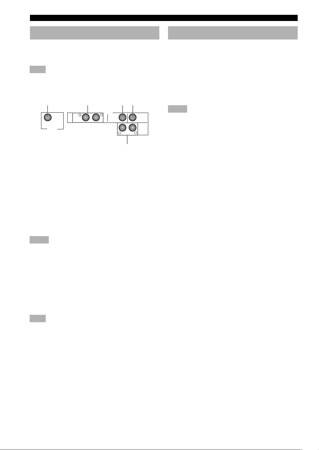
Connecting an external amplifier
If you want to increase the power output to the speakers,
or want to use another amplifier, connect an external
amplifier to the OUTPUT jacks as follows.
Note
• When RCA pin plugs are connected to the OUTPUT jacks for
output to an external amplifier, signals are output from the
SPEAKERS terminals as well.
1
SUB
WOOFER
OUTPUT
1 SUBWOOFER jack
When using a subwoofer with built-in amplifier,
including the YAMAHA Active Servo Processing
Subwoofer System, connect the input jack of the
subwoofer system to this jack. Low bass signals
distributed from the main, center and/or rear channels are
directed to this jack in accordance with your SPEAKER
SET selections. The LFE (low-frequency effect) signals
generated when Dolby Digital or DTS is decoded are also
directed to this jack in accordance with your SPEAKER
SET selections.
Notes
• The cut-off frequency of the SUBWOOFER jack is 90 Hz.
• If you do not use a subwoofer, designate the signals to the main
left and right speakers by changing the settings of SPEAKER
SET item “1E BASS” on the SET MENU.
• Use the control on the subwoofer to adjust its volume level. It
is also possible to adjust the volume level by using this unit’s
remote control (see “ADJUSTING THE LEVEL OF THE
EFFECT SPEAKERS” on page 51).
2 MAIN jacks
Main channel line output jacks.
Note
• The signals output through these jacks are affected by the
BASS and TREBLE settings.
3 REAR CENTER jack
Rear center channel line output jack.
234
OUTPUT
MAIN
R
L
REAR
CENTER
R
REAR
(SURROUND)
CENTER
L
5
Connecting an external decoder
This unit is equipped with 6 additional input jacks (MAIN
left and right, CENTER, SURROUND left and right, and
SUBWOOFER) for discrete multi-channel input from an
external decoder, sound processor, or pre-amplifier.
Connect the output jacks on your external decoder to the
6CH INPUT jacks. Be sure to match the left and right
outputs to the left and right input jacks for the main and
surround channels.
Notes
• When you select 6CH INPUT as the input source, this unit
automatically turns off the digital sound field processor, and
you cannot listen to DSP programs.
• When you select 6CH INPUT as the input source, settings of
“1 SPEAKER SET” on the SET MENU do not apply (except
for “1F MAIN Lv”).
4 CENTER jack
Center channel line output jack.
5 REAR (SURROUND) jacks
Rear channel line output jacks.
18
Page 21
CONNECTIONS
POWER
SLEEP
CODE SET
STANDBY
TRANSMIT
6CH INPUT
SYSTEM
V-AUX
D-TV/CBL
TV INPUTTV MUTE
VOLUME
MUTE
AMP
POWER POWER
AVTV
VCR 1 VCR1/DVR
DVD
MD/CD-R TUNERCD
+–+
–
+
–
TV CHTV VOL
HALL
ENTER-
TAINMENT
ROCK
CONCERT
JAZZ CLUB
A
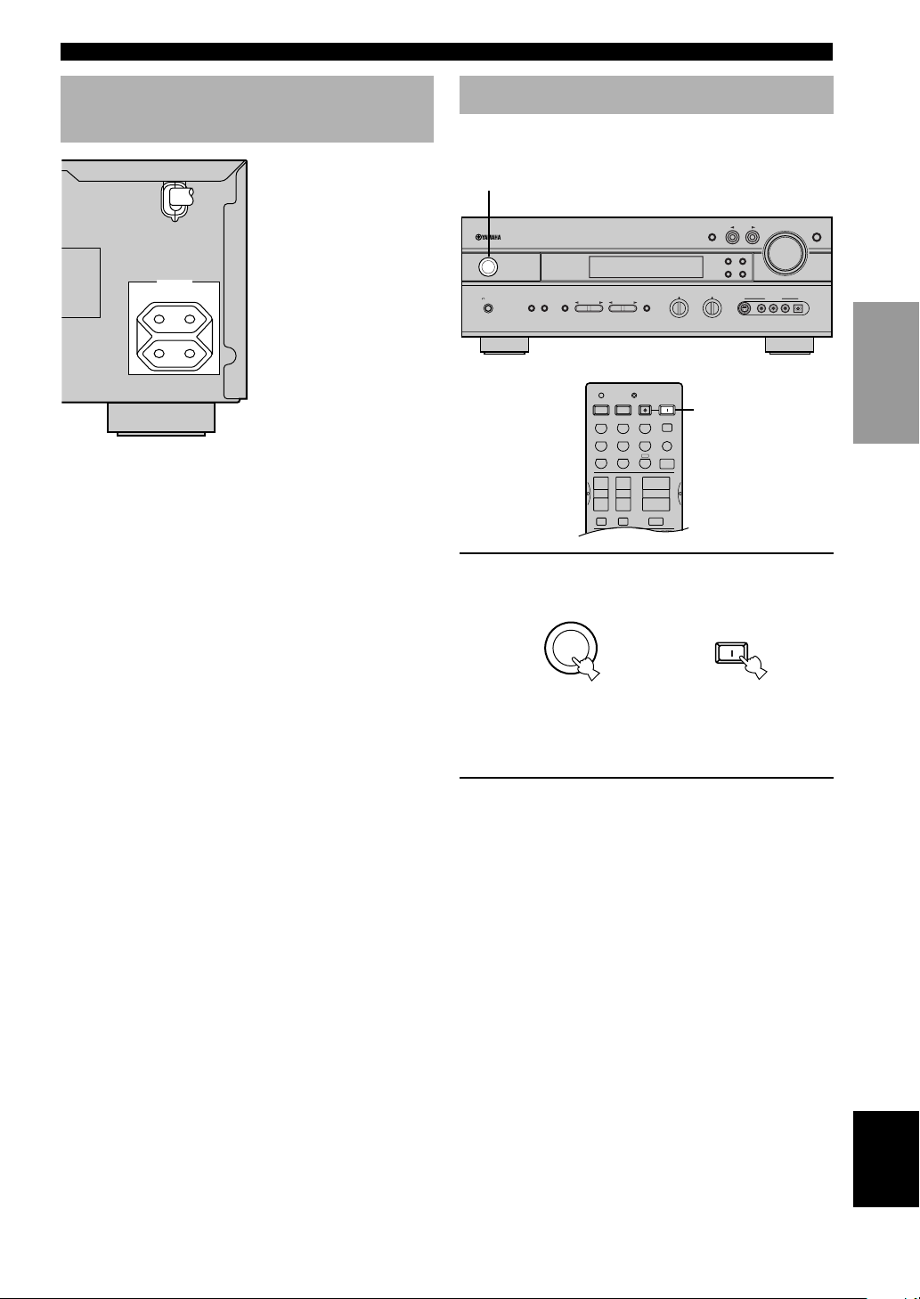
Connecting the power supply cords
AC OUTLETS
SWITCHED
100W MAX. TOTAL
(Europe model)
■ Connecting the AC power cord
Plug in this unit to the wall outlet.
■ AC OUTLETS (SWITCHED)
U.S.A., Canada, China, Europe, Singapore and
General models ..............................................2 OUTLETS
U.K. and Australia model ................................1 OUTLET
Use these outlets to connect the power cords from your
components to this unit. The power to the AC OUTLETS
is controlled by this unit’s STANDBY/ON (or SYSTEM
POWER and STANDBY). These outlets will supply
power to any source component connected to this unit
whenever this unit is turned on. The maximum power
(total power consumption of components) that can be
connected to the AC OUTLETS varies depending on the
area which it was purchasing.
China and General models.........................................50 W
Other models ........................................................... 100 W
Turning on the power
When all connections are complete, turn on the power of
this unit.
1
INPUT
STANDBY
/
ON
SILENT
PHONES
NATURAL SOUND AV RECEIVER
SPEAKERS
AB
INPUT M0DE
PRESET/TUNING
TUNING MODE
AUTO/MAN'L MONO
BASS
PRESET/TUNING
PROGRAM
STEREO
EFFECT
A/B/C/D/E
TREBLE
–+ –+
FM/AM
EDIT
MEMORY
MAN'L/AUTO FM
S VIDEO VIDEO AUDIO OPTICALLR
VOLUME
6CH INPUT
VIDEO AUX
1
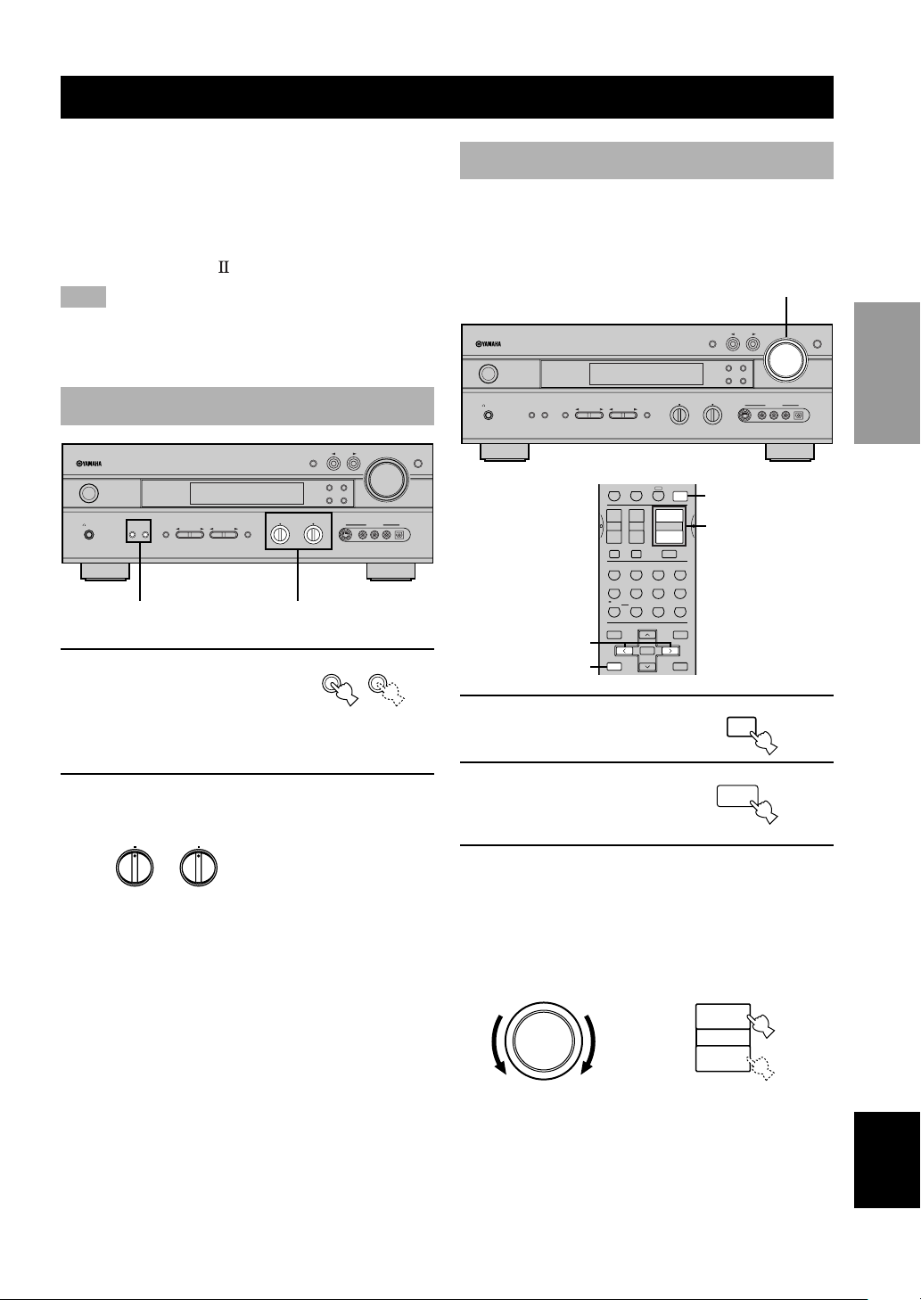
1 Press STANDBY/ON (SYSTEM POWER on
the remote control) to turn on the power of
this unit.
SYSTEM
STANDBY
/ON
Front panel
or
POWER
Remote control
The level of the main volume, and then the current
DSP program name appear on the front panel
display.
2 Turn on the video monitor connected to this
unit.
INTRODUCTION
PREPARATION
BASIC OPERA-
TION
OPERATION
ADVANCED
INFORMATION
ADDITIONAL
APPENDIX
English
19
Page 22

SPEAKER MODE SETTINGS
This unit has 6 SPEAKER SET items on the SET MENU that you must set according to the number of speakers in your
configuration and their size. The following table summarizes these SPEAKER SET items, and shows the initial settings
as well as other possible settings.
If the initial settings shown in the following table are not appropriate for your speaker configuration,
see “1 SPEAKER SET” on pages 43-45 to change the settings.
Summary of SPEAKER SET items 1A through 1F
Item
1A CENTER
1B MAIN
1C REAR LR
1D REAR CT
1E BASS
1F MAIN Lv
Description
Sets center speaker availability and size.
Sets main speaker size.
Sets rear L/R speakers availability and size.
Sets rear center speaker availability and size.
Sets the speaker(s) to be used to output low bass signals.
Sets the main speaker level.
Possible settings (default
setting indicated in bold)
LRG/SML/NON
LARGE/SMALL
LRG/SML/NON
LRG/SML/NON
SWFR/MAIN/BOTH
Nrm (Normal)/–10 dB
20
Page 23
ADJUSTING SPEAKER OUTPUT LEVELS
VOLUME
This section explains how to adjust speaker output levels
using the test tone generator. When this adjustment is
complete, the output level heard at the listening position
should be the same from each speaker. This is important
for best performance of the digital sound field processor,
and the various decoders (Dolby Digital, Dolby Pro
Logic, Dolby Pro Logic
and DTS).
Note
• Since this unit cannot enter the test mode while headphones are
connected to this unit, be sure to unplug the headphones from
the PHONES jack when using the test tone.
Before you begin
INPUT
NATURAL SOUND AV RECEIVER
STANDBY
/
ON
SILENT
SPEAKERS
AB
PHONES
PRESET/TUNING
PROGRAM
STEREO
EFFECT
A/B/C/D/E
1
1 Press SPEAKERS A or B
BASS
– + – +
2
INPUT M0DE
PRESET/TUNING
EDIT
TUNING MODE
AUTO/MAN'L MONO
TREBLE
VOLUME
FM/AM
MEMORY
MAN'L/AUTO FM
VIDEO AUX
S VIDEO VIDEO AUDIO OPTICALLR
SPEAKERS
AB
6CH INPUT
to select the main
speakers to be used.
If you are using two sets of the
main speakers, press both A
and B.
2 Set the BASS and TREBLE controls on the
front panel to the center position.
BASS
–
TREBLE
–
+
+
Using the test tone
Use the test tone to balance the output levels of the
speakers. The adjustment of each speaker output level
should be made at your listening position using the
remote control.
3
INPUT
FM/AM
EDIT
MEMORY
MAN'L/AUTO FM
S VIDEO VIDEO AUDIO OPTICALLR
AMP
VOLUME
VIDEO AUX
NATURAL SOUND AV RECEIVER
STANDBY
/
ON
SILENT
SPEAKERS
AB
PHONES
STEREO
EFFECT
2,5
4
PROGRAM
PRESET/TUNING
VCR 1 VCR2/DVR
+
+
TV CHTV VOL
–+–
–
TV INPUTTV MUTE
HALL
JAZZ CLUB
TV
MONO
SPORTS
MOVIE
678
5
/DTS
SUR.
SELECT
90
LEVEL
TITLE
–
TEST
RETURN
A/B/C/D/E
PRESET/CH
SELECT
CONCERT
THEATER 1
A
VOLUME
MUTE
ROCK
3421
MOVIE
EX/ES
+10
1 Press AMP.
2 Press TEST to output the
test tone.
BASS
– + – +
AMP
ENTER-
TAINMENT
MOVIE
THEATER 2
STEREO
ENTER
EFFECT
SET MENU
MENU
A/B/C/D/E
+
DISPLAY
INPUT M0DE
TREBLE
1
3
PRESET/TUNING
TUNING MODE
AUTO/MAN'L MONO
TEST
RETURN
3 Adjust the volume of this unit so you can
hear the test tone.
The test tone is heard (in order) from the main left
speaker, center speaker, main right speaker, rear right
speaker, rear center, rear left speaker, and the
subwoofer. The tone is produced for 2.5 seconds
from each speaker.
6CH INPUT
INTRODUCTION
PREPARATION
BASIC OPERA-
TION
OPERATION
ADVANCED
INFORMATION
ADDITIONAL
APPENDIX
+
or
VOLUME
–
Remote controlFront panel
English
21
Page 24

ADJUSTING SPEAKER OUTPUT LEVELS
LEFT
CENTER
*
SUBWOOFER
LEFT SURROUND RIGHT SURROUND
REAR CENTER
RIGHT
* Subwoofer test tone is output after the rear left
speaker (LEFT SURROUND).
The front panel display shows which speaker is
outputting the test tone.
Note
• If the test tone cannot be heard, turn down the volume, set this
unit to standby mode and check the speaker connections.
4 Adjust the level of the
effect speakers using j / i
so that it matches the
PRESET/CH
SELECT
–
level of the main
speakers.
While adjusting, the test tone
is heard from the selected
speaker.
Note
• To adjust the level of the main speakers, use VOLUME knob
(or VOLUME +/– on the remote control).
5 When adjustment is
complete, press TEST to
TEST
RETURN
stop the test tone.
Notes
• If “1A CENTER” on the SET MENU is set to NON, the center
channel sound is automatically output from the main left and
right speakers.
• If “1C REAR LR” on the SET MENU is set to NON, the
output level of the rear left, right and center speakers cannot be
adjusted in step 4. The test tone will be circulated skipping the
rear left and right speakers and the rear center speaker.
• If “1D REAR CT” on the SET MENU is set to NON, the
output level of the rear center speaker cannot be adjusted in
step 4. The test tone will be circulated skipping the rear center
speaker.
• If “1E BASS” on the SET MENU is set to MAIN, the test tone
will be circulated skipping the subwoofer.
y
• It is not necessary to readjust the speaker levels once they are
set (as long as you do not change the speakers). You can enjoy
listening to or watching the input source at the desired volume
simply by adjusting the VOLUME knob (or VOLUME +/– on
the remote control).
• If the output level of the effect speakers (center, rear left, rear
right, and rear center) cannot be increased enough to match the
level of the main speakers, set “1F MAIN Lv” on SET MENU
to –10 dB (see page 45). This setting decreases the main
speaker output level to about one-third of the normal level.
After you have set “1F MAIN Lv” on the SET MENU to
–10 dB, adjust the levels for the center and rear speakers again.
+
22
Page 25
BASIC PLAYBACK
V-AUX
D-TV/CBL
VCR 1 VCR2/DVR
DVD
MD/CD-R TUNERCD
1
STANDBY
/
ON
SILENT
PHONES
NATURAL SOUND AV RECEIVER
SPEAKERS
AB
A/B/C/D/E
BASS
– + – +
PRESET/TUNING
PROGRAM
STEREO
EFFECT
73
CODE SET
TRANSMIT
SYSTEM
STANDBY
POWER POWER
DVD
VCR 1 VCR2/DVR
+
–
HALL
TV
SPORTS
5
/DTS
SUR.
90
POWER
AVTV
MD/CD-R TUNERCD
D-TV/CBL
V-AUX
6CH INPUT
A
+–+
VOLUME
TV CHTV VOL
–
TV INPUTTV MUTE
MUTE
ROCK
JAZZ CLUB
CONCERT
TAINMENT
3421
MONO
MOVIE
THEATER 2
MOVIE
THEATER 1
678
STEREO
EX/ES
SELECT
+10
EFFECT
SLEEP
AMP
ENTER-
MOVIE
ENTER
464
INPUT
INPUT M0DE
PRESET/TUNING
FM/AM
EDIT
TUNING MODE
MEMORY
AUTO/MAN'L MONO
MAN'L/AUTO FM
TREBLE
S VIDEO VIDEO AUDIO OPTICALLR
6
1
44
6
7
VOLUME
VIDEO AUX
1 Press STANDBY/ON (SYSTEM POWER on
the remote control) to turn on the power.
SYSTEM
STANDBY
/ON
Front panel
or
POWER
Remote control
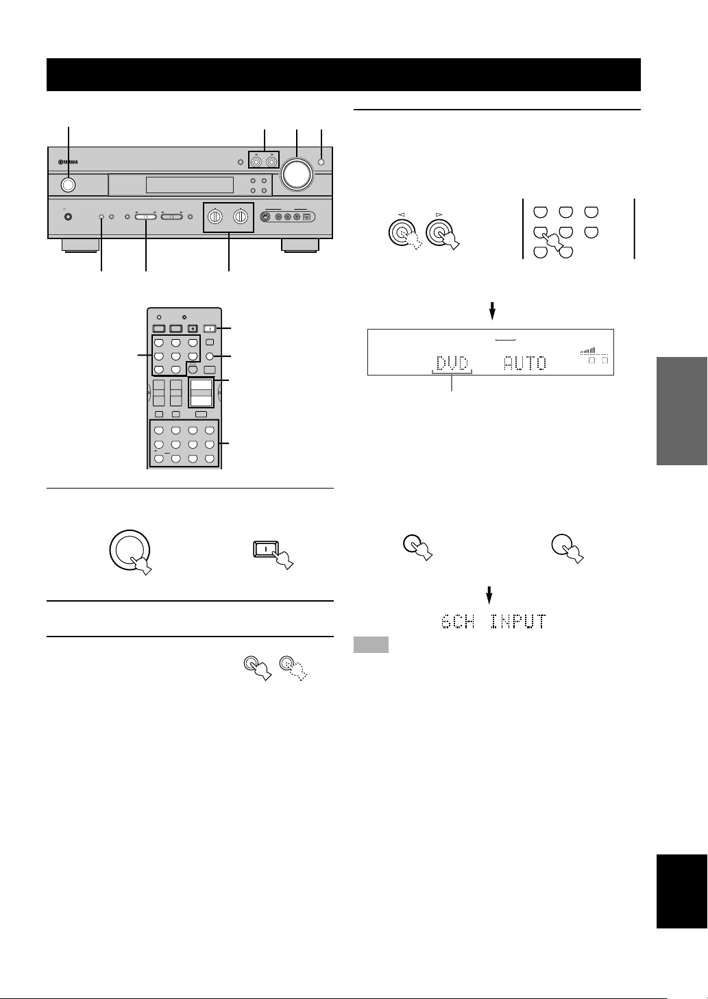
4 Press INPUT l / h repeatedly (one of the
input selector buttons on the remote control)
6CH INPUT
to select the input source.
The selected input source name and input mode
appear on the front panel display for a few seconds.
INPUT
or
DVD
MD/CD-R
Remote control
TUNER CD
Front panel
VCR
VCR2/DVR
V-AUX
D-TV/CBL
1
Selected input source
To select the audio source connected to the 6CH
INPUT jacks
(When combining with a video source)
• You need to select the input to which the video source
component is connected before selecting audio source.
Press 6CH INPUT until “6CH INPUT” appears on the
front panel display.
6CH INPUT
or
6CH INPUT
Remote controlFront panel
VOLUME
LR
INTRODUCTION
PREPARATION
OPERATION
BASIC
OPERATION
ADVANCED
2 Turn on the video monitor connected to this
unit.
3 Press SPEAKERS A or B
to select the main
speakers to be used.
If you are using two sets of
main speakers, press both A
and B.
SPEAKERS
AB
Note
• If “6CH INPUT” is shown on the front panel display, no other
source can be played. To select another input source, first press
6CH INPUT to turn off “6CH INPUT” from the front panel
display.
23
INFORMATION
ADDITIONAL
APPENDIX
English
Page 26
BASIC PLAYBACK
V-AUX
D-TV/CBL
VCR 1 VCR2/DVR
DVD
MD/CD-R TUNERCD
5 Start playback or select a broadcast station
on the source component.
Refer to the operation instructions for the
component.
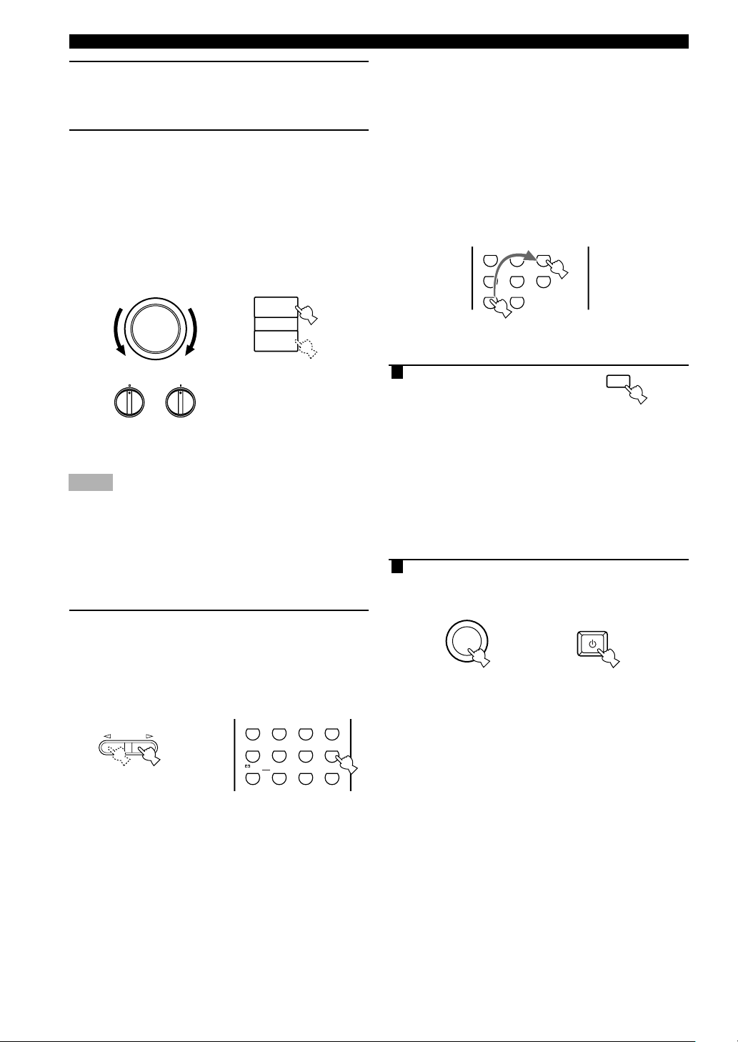
6 Adjust the volume to the desired level.
The volume level is displayed digitally.
Example: –70 dB
Control range: VOLUME MUTE (minimum) to
0 dB (maximum)
The volume level indicator also shows the current
volume level as a bar graph.
If desired, use BASS and TREBLE. These controls
only effect the sound from the main speakers.
VOLUME
+
or
VOLUME
–
BASS
–
TREBLE
–
+
Front panel
Remote control
+
Notes
• If you increase or decrease the high-frequency or the lowfrequency sound to an extreme level, the tonal quality from the
center and rear speakers may not match that of the main left
and right speakers.
• If you have connected a recording component to the VCR 1
OUT, VCR 2/DVR OUT, or MD/CD-R OUT jacks, and you
notice distortion or low volume during playback of other
components, try turning the recording component on.
7 Select a DSP program if desired.
Use PROGRAM l / h (DSP program buttons on
the remote control) to select a DSP program. See
pages 29 to 33 for details about DSP programs.
When using the remote control, press AMP before
selecting a DSP program.
ENTER-
PROGRAM
or
HALL
TV
SPORTS
5
/DTS
SUR.
90
Front panel Remote control
ROCK
JAZZ CLUB
CONCERT
TAINMENT
3421
MOVIE
THEATER 1
EX/ES
+10
MOVIE
THEATER 2
STEREO
ENTER
EFFECT
MONO
MOVIE
678
SELECT
■ BGV (background video) function
The BGV function allows you to enjoy video images
from a video source together with sounds from an audio
source. For example, you can enjoy listening to classical
music while having beautiful scenery from a video source
on the video monitor.
Select a source from the video group, then select a source
from the audio group using the input selector buttons on
the remote control. BGV selections cannot be made with
INPUT l / h on the front panel.
■ To mute the sound
1 Press MUTE on the
remote control.
To resume the audio output,
press MUTE again.
MUTE
y
• You can also cancel mute by pressing VOLUME +/–, etc.
• During muting, the “MUTE” indicator flashes on the front
panel display.
■ When you have finished using
this unit
1 Press STANDBY/ON (STANDBY on the
remote control) to set this unit in the
standby mode.
STANDBY
STANDBY
/ON
Front panel
or
Remote control
24
Page 27
BASIC PLAYBACK
V-AUX
D-TV/CBL
VCR 1 VCR2/DVR
DVD
MD/CD-R TUNERCD
Input modes and indications
This unit comes with a variety input jacks. You can select
the type of input signals you desire.
Each time you turn on the power of this unit, the input
mode is set according to “8 INPUT MODE” setting on
the SET MENU (see page 47 for details).
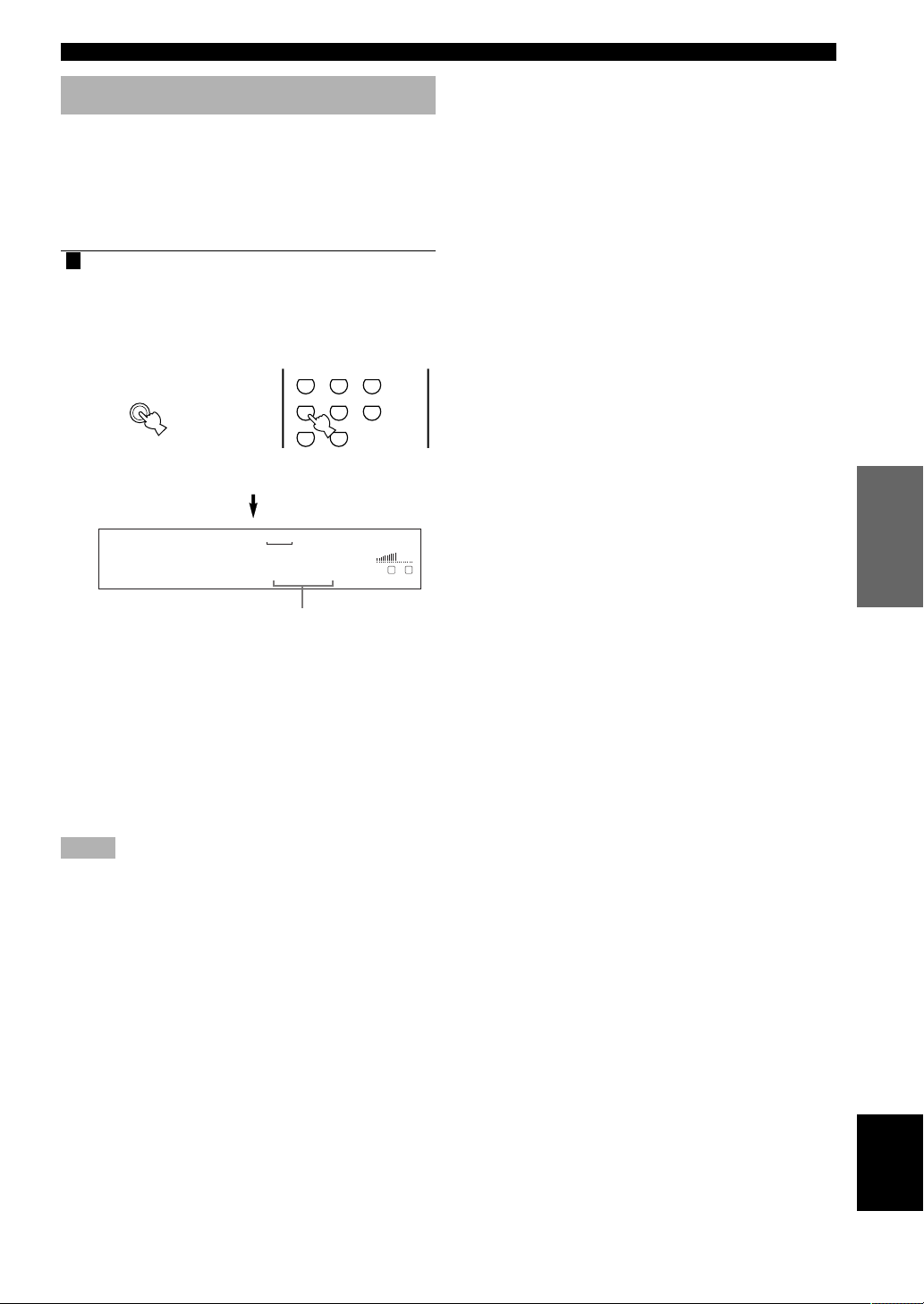
1 Press INPUT MODE (the input selector
button that you have pressed to select the
input source on the remote control)
repeatedly until the desired input mode is
shown on the front panel display.
INPUT MODE
or
Remote controlFront panel
VCR
V-AUX
1
VCR2/DVR
DVD AUTO
AUTO: In this mode, the input signal is selected
automatically as follows:
1) Digital signal
2) Analog signal
DTS: In this mode, only the digital input signal
encoded with DTS is selected, even if
another signal is input at the same time.
ANALOG: In this mode, only the analog input signal is
selected, even if a digital signal is input at
the same time.
Notes
• When AUTO is selected, this unit automatically determines the
type of signal. If this unit detects a Dolby Digital or DTS
signal, the decoder automatically switches to the appropriate
setting.
• When playing a disc encoded with Dolby Digital or DTS on
some LD or DVD players, the sound output delays for a
moment when playback resumes after a search because the
digital signal is selected again.
• When playing a LD source that has not been digitally recorded,
the sound may not be output for some LD players. In this case,
set the input mode to ANALOG.
D-TV/CBL
DVD
MD/CD-R
Input mode
TUNER CD
VOLUME
LR
■ Notes on 96-kHz sampling digital
signals
The digital input jacks of this unit can handle 96-kHz
sampling digital signals. Note the following when 96-kHz
sampling digital signal is input to this unit:
– DSP programs cannot be selected.
– Sound will be output as 2-channel stereo from only the
main left and right speakers. (There may be sound
output from the subwoofer depending on the
SPEAKER MODE settings on the SET MENU.)
Therefore, the level of the effect speakers cannot be
adjusted while listening to such a source.
■ Notes on playing DTS-CD/LDs
• If the digital output data of the player has been
processed in any way, you may not be able to perform
DTS decoding even if you make a digital connection
between this unit and the player.
• If you play a source encoded with a DTS signal and
set the input mode to ANALOG, this unit may
reproduce the noise of an unprocessed DTS signal. In
this case, connect the source to a digital input jack and
set the input mode to AUTO or DTS.
• If you switch the input mode to ANALOG while
playing a source encoded with a DTS signal, this unit
reproduces no sound.
• If you play a source encoded with a DTS signal with
the input mode set to AUTO;
–This unit automatically switches to the DTS-
decoding mode (The “t” indicator lights up) after
having detected the DTS signal. When playback of
the DTS source is completed, the “t” indicator
may flash. While this indicator is flashing, only DTS
source can be played. If you want to play a normal
PCM source soon, set the input mode back to AUTO.
–When the input mode is set to AUTO and a search or
skip operation is performed during playback of a
DTS source, the “t” indicator may flash. If this
status continues for longer than 30 seconds, this unit
will automatically switch from “DTS-decoding”
mode to PCM digital signal input mode. The “t”
indicator will turn off.
INTRODUCTION
PREPARATION
OPERATION
BASIC
OPERATION
ADVANCED
INFORMATION
ADDITIONAL
APPENDIX
English
25
Page 28
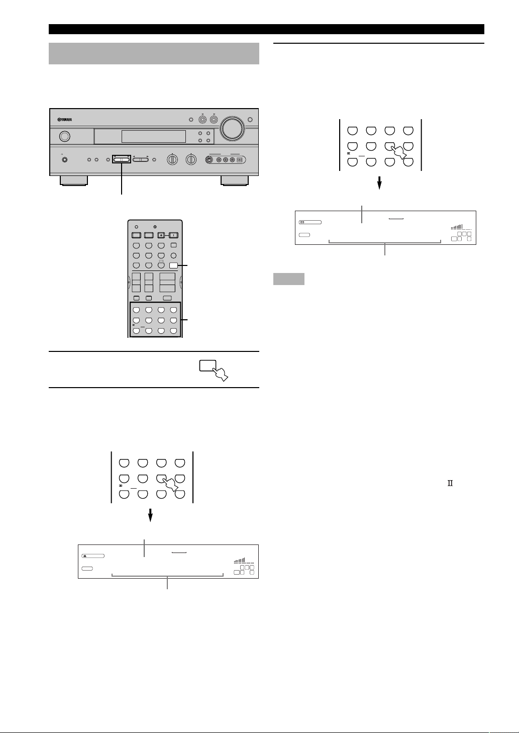
BASIC PLAYBACK
DGTLz Sci-Fi
RL
LCR
RR
LFE
DSP
DIGITAL
VOLUME
MOVIE
THTR
1
VCR
V-AUX
DVD
TUNER CD
D-TV/CBL
MD/CD-R
1
VCR2/DVR
Selecting a sound field program
You can enhance your listening experience by selecting a
DSP program. For details about each program, see pages
29 to 33.
INPUT
FM/AM
MEMORY
MAN'L/AUTO FM
VIDEO AUX
S VIDEO VIDEO AUDIO OPTICALLR
AMP
VOLUME
6CH INPUT
NATURAL SOUND AV RECEIVER
STANDBY
/
ON
SILENT
SPEAKERS
AB
PHONES
STEREO
PROGRAM l / h
1 Press AMP.
INPUT M0DE
PRESET/TUNING
EDIT
TUNING MODE
AUTO/MAN'L MONO
BASS
A
VOLUME
MUTE
ROCK
3421
EX/ES
+10
– + – +
SYSTEM
POWER
SLEEP
6CH INPUT
AMP
–
ENTER-
TAINMENT
MOVIE
THEATER 2
STEREO
ENTER
EFFECT
TREBLE
1
2,3
PRESET/TUNING
CODE SET
POWER POWER
AVTV
MD/CD-R TUNERCD
D-TV/CBL
DVD
VCR 1 VCR2/DVR
+–+
+
TV CHTV VOL
–
TV INPUTTV MUTE
HALL
JAZZ CLUB
TV
MONO
SPORTS
MOVIE
678
5
/DTS
SUR.
SELECT
90
A/B/C/D/E
TRANSMIT
STANDBY
V-AUX
CONCERT
MOVIE
THEATER 1
PROGRAM
EFFECT
2 Press one of the DSP program buttons on
the remote control to select the desired
program.
The name of the selected program appears on the
front panel display.
ENTER-
HALL
TV
SPORTS
5
/DTS
SUR.
90
Program name
VCR
VCR2/DVR
DIGITAL
DSP
DGTL Spectacle
ROCK
JAZZ CLUB
CONCERT
TAINMENT
3421
MOVIE
THEATER 1
EX/ES
+10
D-TV/CBL
1
MOVIE
THEATER 2
STEREO
ENTER
EFFECT
DVD
MONO
MOVIE
678
SELECT
V-AUX
1
THTR
MOVIE
Sub-program name
MD/CD-R
TUNER CD
VOLUME
LFE
LCR
RL
3 After selecting the desired program, press
the same button repeatedly to select the
desired sub-program if available.
Example: Pressing MOVIE THEATER 1 repeatedly
switches the sub-program between
“Sci-Fi” and “Spectacle”.
ENTER-
HALL
TV
SPORTS
5
/DTS
SUR.
90
Program name
Notes
• There are 9 programs with sub-programs available with this
unit. However, the selection depends on the input signal format
and not all sub-programs can be used with all input signal
formats.
• The digital sound field processor cannot be used when a source
connected to the 6CH INPUT jacks of this unit is selected or
when 96-kHz sampling digital signals are input to this unit.
• The acoustics of your listening room affect the DSP program.
Minimize the sound reflections in your room to maximize the
effect created by the program.
• When you select an input source, this unit automatically selects
the last DSP program used with that source.
• When you set this unit in the standby mode, the current source
and DSP program are memorized and are automatically
selected when you turn on the power again.
• If a Dolby Digital or DTS signal is input when the input mode
is set to AUTO, the DSP program (No. 7–9) automatically
switches to the appropriate decoding program.
• When a monaural source is being played with PRO LOGIC/
Normal or PRO LOGIC/Enhanced, or PRO LOGIC Movie,
no sound will be heard from the main speakers and the rear
speakers. Sound can only be heard from the center speaker. (If
“1A CENTER” on the SET MENU is set to NON, the center
channel sound is output from the main speakers.)
y
• You can also select DSP program by pressing PROGRAM
l / h on the front panel.
RR
• Select a program based on your listening preference. Program
names are just for reference.
ROCK
JAZZ CLUB
CONCERT
TAINMENT
3421
MOVIE
THEATER 1
EX/ES
+10
MOVIE
THEATER 2
STEREO
ENTER
EFFECT
MONO
MOVIE
678
SELECT
Sub-program name
26
Page 29
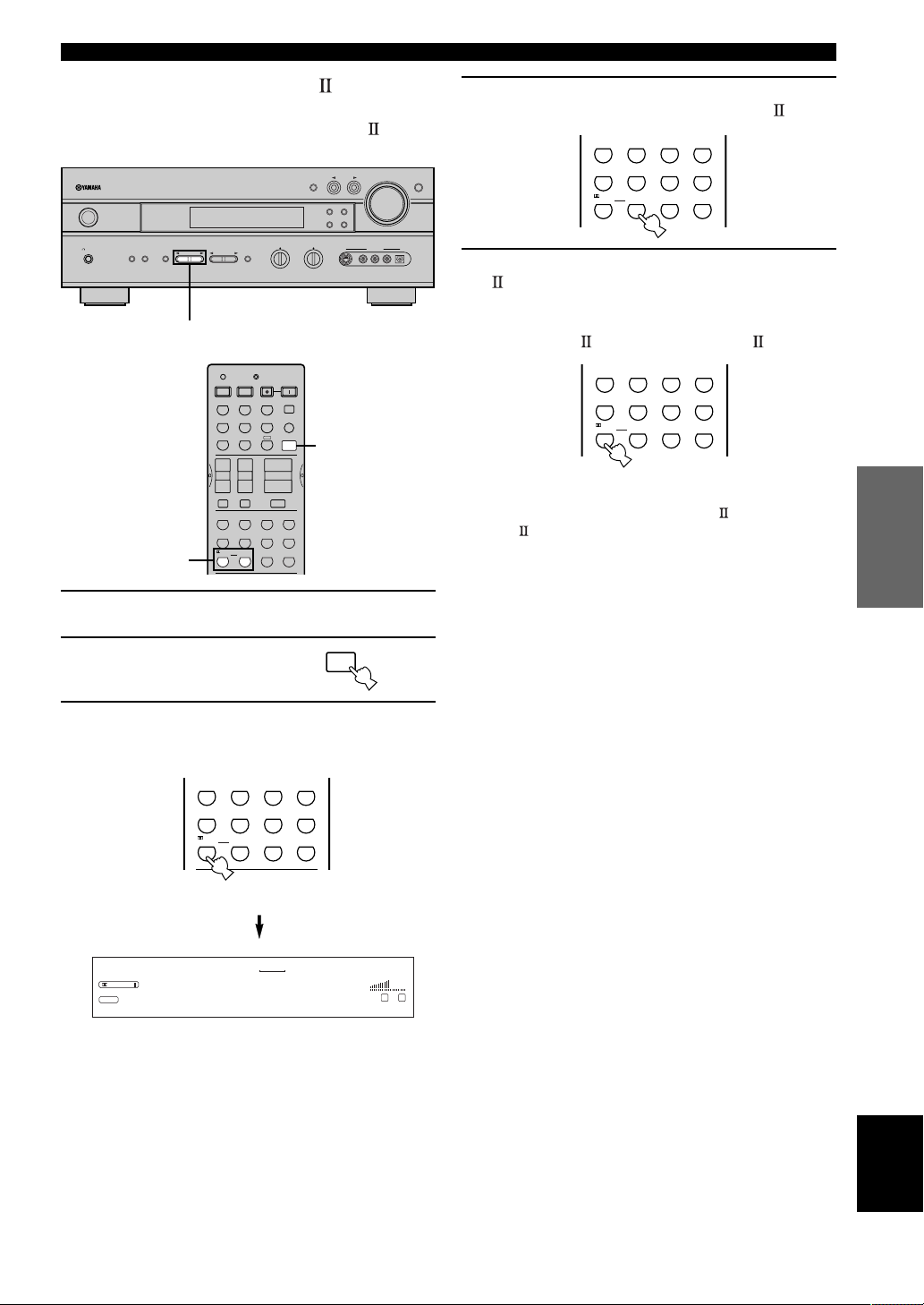
BASIC PLAYBACK
■ Selecting PRO LOGIC
You can enjoy the 2-channel sources decoded into five or
six discrete channels by selecting PRO LOGIC
in
program No. 9.
INPUT
STANDBY
/
ON
SILENT
PHONES
NATURAL SOUND AV RECEIVER
SPEAKERS
AB
STEREO
PROGRAM l / h
3,4,5
INPUT M0DE
PRESET/TUNING
EDIT
TUNING MODE
AUTO/MAN'L MONO
BASS
STANDBY
V-AUX
CONCERT
THEATER 1
A
VOLUME
MUTE
ROCK
3421
MOVIE
EX/ES
+10
– + – +
SYSTEM
POWER
SLEEP
6CH INPUT
AMP
–
ENTER-
TAINMENT
MOVIE
THEATER 2
STEREO
ENTER
EFFECT
TREBLE
2
PRESET/TUNING
PROGRAM
EFFECT
A/B/C/D/E
CODE SET
POWER POWER
AVTV
MD/CD-R TUNERCD
D-TV/CBL
DVD
VCR 1 VCR2/DVR
+–+
+
TV CHTV VOL
–
TV INPUTTV MUTE
HALL
JAZZ CLUB
TV
MONO
SPORTS
MOVIE
678
5
/DTS
SUR.
SELECT
90
TRANSMIT
FM/AM
MEMORY
MAN'L/AUTO FM
VIDEO AUX
S VIDEO VIDEO AUDIO OPTICALLR
VOLUME
6CH INPUT
1 Select a 2-channel source and start playback
on the source component.
2 Press AMP.
AMP
4 Press SELECT repeatedly to select the
decoder; PRO LOGIC or PRO LOGIC
ENTER-
HALL
TV
SPORTS
5
/DTS
SUR.
90
ROCK
JAZZ CLUB
CONCERT
TAINMENT
3421
MOVIE
MOVIE
MONO
MOVIE
SELECT
THEATER 2
THEATER 1
678
EX/ES
+10
STEREO
ENTER
EFFECT
.
5 After selecting on the decoder (PRO LOGIC
), select the mode appropriate for the
source by pressing q/DTS SUR.
The selection switches as follow;
PRO LOGIC
y
• You can select PRO LOGIC, PRO LOGIC Movie, and PRO
LOGIC Music by pressing PROGRAM l / h on the front
panel repeatedly.
Movie ↔ PRO LOGIC Music
ENTER-
HALL
TV
SPORTS
5
/DTS
SUR.
90
ROCK
JAZZ CLUB
CONCERT
TAINMENT
3421
MOVIE
MOVIE
MONO
MOVIE
678
SELECT
THEATER 1
EX/ES
+10
THEATER 2
STEREO
ENTER
EFFECT
INTRODUCTION
PREPARATION
OPERATION
BASIC
OPERATION
ADVANCED
3 Press q/DTS SUR.
The previously selected sub program appears on the
front panel display.
ENTER-
HALL
TV
SPORTS
5
/DTS
SUR.
90
Remote control
VCR
V-AUX
1
VCR2/DVR
/
PRO LOGIC
DSP
PRO LOGIC
ROCK
JAZZ CLUB
CONCERT
TAINMENT
3421
THEATER 1
PRO LOGIC
MOVIE
EX/ES
DVD
MOVIE
THEATER 2
STEREO
ENTER
+10
EFFECT
MD/CD-R
MONO
MOVIE
678
SELECT
D-TV/CBL
TUNER CD
VOLUME
LR
INFORMATION
ADDITIONAL
APPENDIX
English
27
Page 30
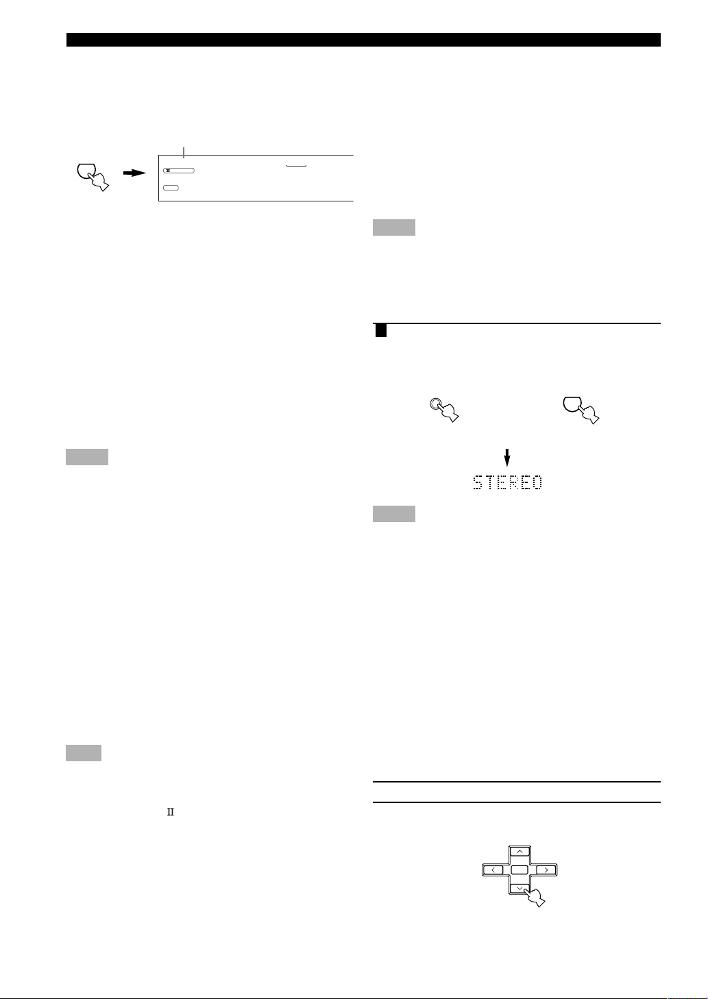
BASIC PLAYBACK
■ Playing Dolby Digital Surround
EX or DTS ES software
Press EX/ES to turn on the Dolby Digital EX or DTS-ES
compatible decoder.
The MATRIX indicator lights up.
EX/ES
+10
DSP
MATRIX
DIGITAL
VCR
V-AUX
1
VCR2/DVR
MOVIE
THTR
Spectacle EX
1
D-TV/CBL
DVD
MD/CD-R
TUNER
The display changes AUTO → Matrix6.1 → OFF each
time the EX/ES button is pressed.
AUTO: This mode automatically switches Dolby
Digital EX and DTS-ES compatible
depending on the signal. Rear center speaker
does not work for 5.1 channel sources.
Matrix6.1: This setting produces 6-channel playback of
the input source using the Dolby Digital EX
or DTS-ES compatible decoder. The rear
center speaker can be used when playing a
5.1-channel source.
OFF: Rear center speaker does not work in this
setting. (Except for when the DSP program
“6ch” is selected.)
Notes
• No sound will be output from the rear center speaker if you
have set “1C REAR LR” or “1D REAR CT” on the SET
MENU to NON.
• The setting becomes AUTO once this unit turns into standby
mode.
• Some Dolby Digital Surround EX or DTS ES software may not
contain the signal that is necessary for this unit to switch to the
Dolby Digital EX or DTS-ES compatible decoding mode. To
turn on the decoder when playing such a source, select
“Matrix6.1”.
■ Virtual CINEMA DSP
With Virtual CINEMA DSP, you can enjoy all DSP
programs without rear speakers. It creates virtual speakers
to reproduce a natural sound field.
You can listen to virtual CINEMA DSP by setting “1C
REAR LR” in the SET MENU to NON. Sound field
processing changes to VIRTUAL CINEMA DSP
automatically.
Note
• This unit is not set in the virtual CINEMA DSP mode even if
“1C REAR LR” is set to NON in the following cases:
– when the 6ch Stereo, DOLBY DIGITAL Normal, Pro Logic
Normal, Pro Logic , or DTS Normal program is selected;
– when the sound effect is turned off;
– when 6CH INPUT is selected as the input source;
– when 96-kHz sampling digital signals are input to this unit;
– when using the test tone; or
– when connecting the headphones.
■ SILENT CINEMA DSP
You can enjoy a powerful sound field similar to what you
could expert from actual speakers with SILENT
CINEMA DSP. You can listen to SILENT CINEMA DSP
by connecting your headphones to the PHONES jack
while the digital sound field processor is on. Enjoy all the
DSP program using the headphones. The “SILENT”
indicator lights up on the front panel display. (When
sound effects are off, you listen to the source with normal
stereo reproduction.)
Notes
• This feature is not available when 6CH INPUT is selected or
96-kHz sampling digital signals are input to this unit.
• The sound of LFE channel will be mixed and output from the
headphone.
■ Normal stereo reproduction
1 Press STEREO to turn off the sound effect
for normal stereo reproduction.
Press STEREO again to turn the sound effect back
on.
STEREO
EFFECT
Front panel
or
STEREO
ENTER
EFFECT
Remote control
Notes
• If you turn off the sound effects, no sound is output from the
center speaker, rear speakers, or rear center speaker.
• If you turn off the sound effects while a Dolby Digital or DTS
signal is being output, the dynamic range of the signal is
automatically compressed and the sounds of the center and rear
speaker channels are mixed and output from the main speakers.
• The volume may be greatly reduced when you turn off the
sound effects or if you set “4 D. RANGE” on the SET MENU
to MIN. In this case turn on the sound effect.
• The sound of LFE channel will be directed to the main left and
right or the subwoofer (or both) channels depending on the
setting of “1E BASS” on the SET MENU.
y
During stereo reproduction, you can display information such as
the type, format and sampling frequency of the signal input from
the components connected to this unit.
(While playing a source)
1 Press AMP.
2 Press d to display the information about the
input signal.
PRESET/CH
SELECT
–
+
28
Page 31

DIGITAL SOUND FIELD PROCESSING (DSP)
Understanding sound fields
A sound field is defined as the “characteristic sound reflections of a
particular space.” In concert halls and other music venues, we hear
early reflections and reverberations as well as the direct sound
produced by the artist(s). The variations in the early reflections and
other reverberations among the different music venues is what gives
each venue its special and recognizable sound quality.
YAMAHA sent teams of sound engineers all around the world to
measure the sound reflections of famous concert halls and music
venues, and collect detailed sound field information such as the
direction, strength, range, and delay time of those reflections. Then
we stored this enormous amount of data in the ROM chips of this
unit.
■ Recreating a sound field
Recreating the sound field of a concert hall or an opera house requires localizing the virtual sound sources in your
listening room. The traditional stereo system that uses only two speakers is not capable of recreating a realistic sound
field. YAMAHA’s DSP requires four effect speakers to recreate sound fields based on the measured sound field data.
The processor controls the strength and delay time of the signals output from the four effect speakers to localize the
virtual sound sources and fully encompass the listener.
Hi-Fi DSP programs
INTRODUCTION PREPARATION
OPERATION
BASIC
The following list gives you a brief description of the sound fields produced by each of the DSP programs. Keep in
mind that most of these are precise digital recreations of actual acoustic environments.
No.
1
2
3
4
Program
CONCERT HALL
JAZZ CLUB
ROCK CONCERT
ENTERTAINMENT/
Disco
ENTERTAINMENT/
6ch Stereo
Features
A large round concert hall with a rich surround effect. Pronounced reflections from all directions
emphasize the extension of sounds. The sound field has a great deal of presence, and your virtual
seat is near the center, close to the stage.
This is the sound field at stage front in “The Bottom Line”, a famous New York jazz club, that
seats up to 300 people. Its wide left to right seating arrangement offers a real and vibrant sound.
The ideal program for lively, dynamic rock music. The data for this program was recorded at
LA’s “hottest” rock club. The listener’s virtual seat is at the center-left of the hall.
This program recreates the acoustic environment of a lively disco in the heart of a big city. The
sound is dense and highly concentrated. It is also characterized by a high-energy, “immediate”
sound.
Using this program increases the listening position range. This is a sound field suitable for
background music at parties, etc.
OPERATION
ADVANCED
INFORMATION
ADDITIONAL
APPENDIX
English
29
Page 32

CINEMA-DSP
Sound design of CINEMA-DSP
Filmmakers intend for the dialog to be located right on the screen, the effect sound a little farther back, the music spread
even farther back, and the surround sound around the listener. Of course, all of these sounds must be synchronized with
the images on the screen.
CINEMA-DSP is an upgraded version of YAMAHA DSP specially designed for movie soundtracks. CINEMA-DSP
integrates the DTS, Dolby Digital, and Dolby Pro Logic surround sound technologies with YAMAHA DSP sound field
programs to provide a surround sound field. It recreates comprehensive movie sound design in your audio room. In
CINEMA-DSP sound field programs, YAMAHA’s exclusive DSP processing is added to the Main left and right, and
Center channels, so the listener can enjoy realistic dialogue, depth of sound, smooth transition between sound sources,
and a surround sound field that goes beyond the screen.
When a DTS or Dolby Digital signal is detected, the CINEMA-DSP sound field processor automatically chooses the
most suitable sound field program for that signal.
L SURROUND SOUND FIELD
PRESENCE SOUND FIELD
EFFECT MUSIC
DIALOG
R SURROUND SOUND FIELD
In addition to the DSP, this unit is equipped with a variety of precise decoders; Dolby Pro Logic decoder for Dolby
Surround sources, Dolby Pro Logic
for multi-channel sources and Dolby Digital EX or DTS-ES compatible decoder for adding a rear center channel. You
can select CINEMA-DSP programs to optimize these decoders and the DSP sound patterns depending on the input
source.
decoder for Dolby Surround and 2-channel sources, Dolby Digital/DTS decoder
30
Page 33

CINEMA-DSP
The 6-channel soundtracks found on 70-mm film produce precise sound field localization and rich, deep sound without
using matrix processing. This unit’s MOVIE THEATER programs provide the same quality of sound and sound
localization that 6-channel soundtracks do. The built-in Dolby Digital or DTS decoder brings the professional-quality
sound designed for movie theaters into your home. With this unit’s MOVIE THEATER programs, you can use Dolby
Digital or DTS technology to recreate a dynamic sound that gives you the feeling of being in a public theater.
■ Dolby Digital/DTS + DSP sound field effect
Presence DSP
sound field
These programs use YAMAHA’s tri-field DSP processing
on each of the Dolby Digital or DTS signals for the front,
left surround, and right surround channels. This
processing enables this unit to reproduce the immense
sound field and surround expression of a Dolby Digitalor DTS-equipped movie theater without sacrificing the
clear separation of all channels.
INTRODUCTION PREPARATION
Left surround DSP
sound field
Right surround DSP
sound field
■ Dolby Digital EX/DTS-ES compatible + DSP sound field effect
These programs provide you with the maximum experience of the spacious surround effects by adding an extra rear
center DSP sound field created from the rear center channel.
■ Dolby Pro Logic + DSP sound field effect
Most movie software has 4-channel (left, center, right,
Presence DSP
sound field
and surround) sound information encoded by Dolby
Surround matrix processing and stored on the left and
right tracks. These signals are processed by the Dolby Pro
Logic decoder. The MOVIE THEATER programs are
designed to recreate the spaciousness and delicate
nuances of sound that tend to be lost in the encoding and
Surround DSP
sound field
decoding processes.
■ Dolby Pro Logic
Dolby Pro Logic decodes Dolby Surround software into 5 discrete full-range channels (3 channels in front and 2
channels in rear). There are 2 modes; MOVIE for movies and MUSIC for 2-channel audio sources.
OPERATION
BASIC
OPERATION
ADVANCED
INFORMATION
ADDITIONAL
31
APPENDIX
English
Page 34

CINEMA-DSP
CINEMA-DSP programs
■ For movie programs: No. 7 to 9
This unit automatically chooses the appropriate decoder and DSP sound field pattern according to the input signal
format.
Table of Program Names for Each Input Format
2 channel
Stereo
70 mm Spectacle
70 mm Sci-Fi
70 mm Adventure
70 mm General
—
—
—
—
Normal
Enhanced
Movie
Music
5.1 channel
DOLBY DIGITAL
DGTL Spectacle
DGTL Sci-Fi
DGTL Adventure
DGTL General
Normal
Enhanced
—
—
—
—
—
—
DTS
DTS Spectacle
DTS Sci-Fi
DTS Adventure
DTS General
—
—
Normal
Enhanced
—
—
—
—
6.1 channel *
DOLBY DIGITAL
EX
Spectacle EX
Sci-Fi EX
Adventure EX
General EX
Dolby D EX
Enhanced EX
—
—
—
—
—
—
DTS-ES
compatible
Spectacle ES
Sci-Fi ES
Adventure ES
General ES
—
—
DTS-ES
Enhanced ES
—
—
—
—
No.
7
8
9
Input
Program
MOVIE
THEATER 1
MOVIE
THEATER 2
DOLBY
DIGITAL
DTS DIGITAL
SUR
PRO LOGIC
PRO LOGIC
* means the Dolby Digital EX decoder or the DTS-ES compatible decoder is ON.
y
• If a Dolby Digital signal or DTS signal is input when the input mode is set to AUTO, the DSP program will automatically switch to
the Dolby Digital playback sound field or DTS playback sound field.
• If Dolby Digital Surround EX software or DTS ES software is played when AUTO is selected by pressing the EX/ES button on the
remote control, the Dolby Digital EX or DTS-ES compatible decoder usually turns on and the corresponding DSP program is
selected.
• EX/ES on the remote control can be used to play Dolby Digital or DTS 5.1 channel sources with the rear center speaker. In this case
the program name changes to the corresponding name for 6.1 channel.
• When playing a 6.1 channel source with the Dolby Digital EX decoder or the DTS-ES compatible decoder turned off, the program
name changes to the corresponding name for 5.1 channel.
Notes
• The “ ” indicator does not light up when selecting program No. 9 except in Enhanced mode.
• When playing a monaural source with a CINEMA DSP program, the source signal is directed to the center channel, main and rear
speakers output effect sounds.
32
Page 35

CINEMA-DSP
The following list gives you a brief description of the sound fields produced by each of the DSP programs. Keep in
mind that most of these are precise digital recreations of actual acoustic environments. Select the DSP program that you
feel sounds best regardless of the name and description given for it below.
No.
Program
Features
INTRODUCTION PREPARATION
7
8
9
MOVIE
THEATER 1
MOVIE
THEATER 2
Enhanced Mode
Spectacle
Sci-Fi
Adventure
General
This program creates the extremely wide sound field of a 70-mm movie theater. It
precisely reproduces the source sound in detail, making both the video and the sound
field incredibly real. This is ideal for any kind of video source encoded with Dolby
Surround, Dolby Digital or DTS (especially large-scale movie productions).
This program clearly reproduces dialog and sound effects in the latest sound form of
science fiction films, thus creating a broad and expansive cinematic space amid the
silence. You can enjoy science fiction films in a virtual-space sound field that includes
Dolby Surround, Dolby Digital and DTS-encoded software employing the most advanced
techniques.
This program is ideal for precisely reproducing the sound design of the newest 70-mm
and multichannel soundtrack films. The sound field is made to be similar to that of the
newest movie theaters, so the reverberations of the sound field itself are restrained as
much as possible.
This program is for reproducing sounds from 70-mm and multichannel soundtrack films,
and is characterized by a soft and extensive sound field. The presence sound field is
relatively narrow. It spatially spreads all around and toward the screen, restraining the
echo effect of conversations without losing clarity.
This program ideally simulates the multi-surround speaker systems of the 35-mm film
theaters. Dolby Pro Logic decoding, Dolby Digital decoding or DTS decoding and digital
sound field processing create precise effects without altering the original sound
orientation.
The surround effects produced by this sound field wrap around the viewer naturally from
the back to the left and right, and toward the screen.
OPERATION
BASIC
OPERATION
ADVANCED
■ For audio-video sources: No. 4 to 6
No.
4
5
6
Program
ENTERTAINMENT/
Game
ENTERTAINMENT/
Concert Video
TV SPORTS
MONO MOVIE
This program adds a deep and spatial feeling to video game sounds.
This program adds a deep and spatial feeling to concert video sounds.
With this program, you can enjoy watching various TV programs such as news, variety shows,
music programs or sports programs. In a stereo broadcast of a sports game, the commentator is
oriented at the center position, and the shouts and the atmosphere in the stadium spread on the
surround side, while their spread to the rear is properly restrained.
This program is provided for reproducing monaural video sources (such as old movies). The
program produces the optimum reverberation to create sound depth by using only the presence
sound field.
Features
INFORMATION
ADDITIONAL
APPENDIX
English
33
Page 36

TUNING
SYSTEM
/
/
/
Automatic and manual tuning
There are 2 ways to tune; automatic and manual.
Automatic tuning is effective when station signals are
strong and there is no interference.
■ Automatic tuning
1
INPUT
STANDBY
/
ON
SILENT
PHONES
NATURAL SOUND AV RECEIVER
SPEAKERS
AB
INPUT M0DE
PRESET/TUNING
EDIT
TUNING MODE
AUTO/MAN'L MONO
BASS
PRESET/TUNING
PROGRAM
STEREO
EFFECT
A/B/C/D/E
TREBLE
– + – +
FM/AM
MEMORY
MAN'L/AUTO FM
VIDEO AUX
S VIDEO VIDEO AUDIO OPTICALLR
VOLUME
4233
1 Press INPUT l / h (TUNER on the remote
control) to select TUNER as the input source.
INPUT
Front panel
POWER POWER
or
DVD
VCR 1 VCR2/DVR
STANDBY
V-AUX
POWER
6CH INPUT
A
AVTV
MD/CD-R TUNERCD
D-TV/CBL
Remote control
SLEEP
AMP
2 Press FM/AM to select the reception band.
“FM” or “AM” appears on the front panel display.
FM/AM
or
4 Press PRESET/TUNING l / h once to begin
automatic tuning.
Press h to tune in to a higher frequency, or press l
to tune in to a lower frequency.
PRESET/TUNING
VCR
V-AUX
D-TV/CBL
1
DVR
A AM 144O
When tuned in to a station, the “TUNED” indicator
6CH INPUT
lights up and the frequency of the received station is
shown on the front panel display.
y
• Use the manual tuning method if the tuning search does not
stop at the desired station because the signal is weak.
■ Manual tuning
If the signal from the station you want to select is weak,
you must tune in to it manually.
1 Select TUNER and the reception band
following steps 1 and 2 described in
“Automatic tuning” at left.
2 Press TUNING MODE (AUTO/MAN’L MONO)
so that the “AUTO” indicator goes off from
the front panel display.
TUNING MODE
AUTO/MAN'L MONO
If the colon (:) appears on the front panel display,
press PRESET/TUNING (EDIT) to turn it off.
PRESET/TUNING
EDIT
DVR
A AM 144O
VCR
V-AUX
1
AUTO
Goes off
D-TV/CBL
DVD
DVD
MD/CD-R
MD/CD-R
TUNER
TUNED
TUNER
TUNED
3 Press TUNING MODE (AUTO/MAN’L MONO)
so that the “AUTO” indicator lights up on the
front panel display.
TUNING MODE
AUTO/MAN'L MONO
If the colon (:) appears on the front panel display,
AUTO
Lights up
3 Press PRESET/TUNING l / h to tune in to
the desired station manually.
Hold down the button to
continue the tuning search.
Note
• Manually tuning in to an FM station will automatically change
the reception mode to monaural to increase the signal quality.
PRESET/TUNING
press PRESET/TUNING (EDIT) to turn it off.
VCR
V-AUX
1
PRESET/TUNING
EDIT
DVR
A AM 144O
D-TV/CBL
DVD
MD/CD-R
TUNER
TUNED
34
Page 37

TUNING
Presetting stations
■ Automatically presetting stations
(for FM stations)
You can use the automatic preset tuning feature to store
FM stations. This function enables this unit to
automatically tune in to FM stations with strong signals,
and to store up to 40 (8 stations x 5 groups) of those
stations in order. This feature enables you to easily tune in
to any preset station by selecting the preset station
number (see page 37).
INPUT
STANDBY
/
ON
SILENT
PHONES
NATURAL SOUND AV RECEIVER
SPEAKERS
AB
INPUT M0DE
PRESET/TUNING
TUNING MODE
AUTO/MAN'L MONO
BASS
PRESET/TUNING
PROGRAM
STEREO
EFFECT
A/B/C/D/E
TREBLE
–+ –+
23
FM/AM
EDIT
MEMORY
MAN'L/AUTO FM
S VIDEO VIDEO AUDIO OPTICALLR
VOLUME
6CH INPUT
VIDEO AUX
1
1 Press FM/AM to select the FM band.
FM/AM
2 Press TUNING MODE (AUTO/MAN’L MONO)
so that the “AUTO” indicator lights up on the
front panel display.
TUNING MODE
AUTO/MAN'L MONO
AUTO
Lights up
Notes
• Any stored station data existing under a preset number is
cleared when you store a new station under that preset number.
• If the number of the received stations does not reach E8,
automatic preset tuning has automatically stopped after
searching all stations.
• Only FM stations with sufficient signal strength are stored
automatically by automatic preset tuning. If the station you
want to store is weak in signal strength, tune in to it manually
in the monaural mode, and store it by following the procedure
in “Manually presetting stations” on page 36.
Automatic preset tuning options
You can select the preset number from which this unit
will store FM stations and/or begin tuning toward lower
frequencies. After pressing MEMORY in step 3:
1. Press A/B/C/D/E and PRESET/TUNING l / h to
select the preset number under which the first station
will be stored. Automatic preset tuning will stop when
stations have all been stored up to E8.
2. Press PRESET/TUNING (EDIT) to turn off the colon
(:) and then press PRESET/TUNING l to begin
tuning toward lower frequencies.
Memory back-up
The memory back-up circuit prevents the stored data
from being lost even if this unit is set in the standby
mode, the power cord is disconnected from the AC
outlet, or the power supply is temporarily cut due to
power failure. However, if the power is cut for more
than one week, the preset stations may be cleared. If
so, store the stations again.
INTRODUCTION
PREPARATION
OPERATION
BASIC
OPERATION
ADVANCED
3 Press and hold MEMORY (MAN’L/AUTO FM)
for more than 3 seconds.
The preset number and the “MEMORY” and
“AUTO” indicators flash. Then, after about
5 seconds, automatic preset tuning begins from the
frequency currently displayed toward the higher
frequencies.
MEMORY
MAN'L/AUTO FM
VCR
V-AUX
1
VCR2/DVR
A1:FM
When automatic preset tuning is completed, the front
panel display shows the frequency of the last preset
station.
D-TV/CBL
DVD
MD/CD-R
TUNER CD
AUTO
MEMORY
VOLUME
LR
35
INFORMATION
ADDITIONAL
APPENDIX
English
Page 38

TUNING
■ Manually presetting stations
You can also store up to 40 stations (8 stations x 5
groups) manually.
INPUT
STANDBY
/
ON
SILENT
PHONES
NATURAL SOUND AV RECEIVER
SPEAKERS
AB
INPUT M0DE
PRESET/TUNING
EDIT
TUNING MODE
AUTO/MAN'L MONO
BASS
PRESET/TUNING
PROGRAM
STEREO
EFFECT
A/B/C/D/E
TREBLE
– + – +
FM/AM
MEMORY
MAN'L/AUTO FM
VIDEO AUX
S VIDEO VIDEO AUDIO OPTICALLR
VOLUME
6CH INPUT
4 3 2,5
1 Tune in to a station.
See page 34 for tuning instructions.
VCR
V-AUX
1
VCR2/DVR
A AM 63O kHz
D-TV/CBL
DVD
MD/CD-R
TUNER CD
TUNED
VOLUME
LR
When tuned in to a station, the front panel display
shows the frequency of received station.
2 Press MEMORY (MAN’L/AUTO FM).
The “MEMORY” indicator flashes for about
5 seconds.
MEMORY
MAN'L/AUTO FM
MEMORY
Flashes
3 Press A/B/C/D/E repeatedly to select a preset
station group (A to E) while the “MEMORY”
indicator is flashing.
The group letter appears and make sure that the
colon (:) appears on the front panel display.
A/B/C/D/E
4 Press PRESET/TUNING l / h to select a
preset station number (1 to 8) while the
“MEMORY” indicator is flashing.
Press h to select a higher preset station number.
Press l to select a lower preset station number.
PRESET/TUNING
VCR
V-AUX
1
VCR2/DVR
C3:AM 63O kHz
D-TV/CBL
DVD
MD/CD-R
TUNER CD
TUNED
MEMORY
VOLUME
LR
5 Press MEMORY (MAN’L/AUTO FM) on the
front panel while the “MEMORY” indicator is
flashing.
The station band and
frequency appear on the front
MEMORY
MAN'L/AUTO FM
panel display with the preset
group and number you have
selected.
VCR
V-AUX
1
VCR2/DVR
C3:AM 63O kHz
Shows the displayed station has been stored as C3.
D-TV/CBL
DVD
MD/CD-R
TUNER CD
TUNED
VOLUME
LR
6 Repeat steps 1 to 5 to store other stations.
Notes
• Any stored station data existing under a preset number is
cleared when you store a new station under that preset number.
• The reception mode (stereo or monaural) is stored along with
the station frequency.
36
VCR
VCR2/DVR
V-AUX
1
D-TV/CBL
DVD
MD/CD-R
C :AM 63O kHz
TUNER CD
TUNED
MEMORY
VOLUME
LR
Page 39

TUNING
REC
DISC SKIP
SET MENU
SELECT
PRESET/CH
A/B/C/D/E
AUDIO
LEVEL
MENU
TEST
EFFECT
RETURN
DISPLAY
TITLE
+
–
EDIT
PRESET/TUNING
Tuning in to a preset station
You can tune any desired station simply by selecting the
preset station number under which it was stored.
INPUT
STANDBY
/
ON
SILENT
PHONES
NATURAL SOUND AV RECEIVER
SPEAKERS
AB
INPUT M0DE
PRESET/TUNING
EDIT
TUNING MODE
AUTO/MAN'L MONO
BASS
PRESET/TUNING
PROGRAM
STEREO
EFFECT
A/B/C/D/E
1
2
TREBLE
– + – +
FM/AM
MEMORY
MAN'L/AUTO FM
VIDEO AUX
S VIDEO VIDEO AUDIO OPTICALLR
VOLUME
1
2
1 Press A/B/C/D/E (A/B/C/D/E on the remote
control) to select the preset station group.
The preset group letter appears on the front panel
display and changes each time you press A/B/C/D/E.
A/B/C/D/E
or
Front panel
SET MENU
MENU
A/B/C/D/E
Remote control
2 Press PRESET/TUNING l / h (PRESET
u / d on the remote control) to select a
preset station number (1 to 8).
The preset group and number appear on the front
panel display along with the station band, frequency
and the “TUNED” indicator lights up.
PRESET/CH
PRESET/TUNING
or
Front panel
VCR
VCR2/DVR
V-AUX
1
D-TV/CBL
DVD
MD/CD-R
E1:FM 87.5 MHz
SELECT
–
Remote control
TUNER CD
TUNED
+
Exchanging preset stations
You can exchange the assignment of two preset stations.
The example below describes the procedure for
exchanging preset station “E1” with “A5”.
6CH INPUT
NATURAL SOUND AV RECEIVER
STANDBY
/
ON
SILENT
SPEAKERS
AB
PHONES
PRESET/TUNING
PROGRAM
STEREO
EFFECT
A/B/C/D/E
BASS
– + – +
INPUT M0DE
TREBLE
2,41,3 1,3
1 Tune in to preset station “E1” by using the
A/B/C/D/E and PRESET/TUNING l / h.
See “Tuning in to a preset station” at left.
2 Press and hold PRESET/TUNING (EDIT) for
more than 3 seconds.
“E1” and the “MEMORY” indicator flash on the
front panel display.
VCR
V-AUX
D-TV/CBL
1
VCR2/DVR
E1:FM 87.5 MHz
3 Tune in to preset station “A5” by using the
A/B/C/D/E and PRESET/TUNING l / h.
“A5” and the “MEMORY” indicator flash on the
front panel display.
VCR
VCR2/DVR
V-AUX
1
D-TV/CBL
DVD
MD/CD-R
A5:FM 9O.6 MHz
4 Press PRESET/TUNING (EDIT) again.
The stations stored at the two preset assignments are
exchanged.
VCR
V-AUX
D-TV/CBL
1
PRESET/TUNING
EDIT
VCR2/DVR
EDIT E1-A5
Shows the exchange of stations has
been completed.
INPUT
PRESET/TUNING
FM/AM
EDIT
TUNING MODE
MEMORY
AUTO/MAN'L MONO
MAN'L/AUTO FM
S VIDEO VIDEO AUDIO OPTICALLR
DVD
TUNER CD
TUNED
MEMORY
DVD
MD/CD-R
MD/CD-R
VIDEO AUX
VOLUME
VOLUME
TUNER CD
TUNED
MEMORY
LR
TUNER CD
MEMORY
6CH INPUT
INTRODUCTION
PREPARATION
OPERATION
BASIC
OPERATION
ADVANCED
INFORMATION
ADDITIONAL
APPENDIX
English
37
Page 40

RECEIVING RDS STATIONS
RDS (Radio Data System) is a data transmission system by FM stations in many countries.
RDS data contains various information such as PS (Program Service name), PTY (Program Type), RT (Radio Text), CT
(Clock Time), EON (Enhanced Other Networks), etc. The RDS function is carried out among the network stations.
Description of RDS data
This unit can receive, PS, PTY, RT, CT, and EON data
when receiving RDS broadcasting stations.
■ PS (Program Service name)
mode:
The name of the RDS station being received is displayed.
■ PTY (Program Type) mode:
There are 15 program types to classify RDS stations.
NEWS
AFFAIRS
INFO
SPORT
EDUCATE
DRAMA
CULTURE
SCIENCE
VARIED
POP M
ROCK M
M.O.R. M
LIGHT M
CLASSICS
OTHER M
■ RT (Radio Text) mode:
Information about the program (such as the title of the
song, name of the singer, etc.) on the RDS station being
received is displayed by a maximum of 64 alphanumeric
characters, including the umlaut symbol. If other
characters are used for RT data, they are displayed with
under-bars.
■ CT (Clock Time) mode:
The current time is displayed and updated every minute.
If the data are accidentally cut off, “CT WAIT” may
appear.
■ EON (Enhanced Other Networks):
Refer to following page.
News
Current affairs
General information
Sports
Education
Drama
Culture
Science
Light entertainment
Pops
Rock
Middle-of-the-road music
(easy-listening)
Light classics
Serious classics
Other music
Changing the RDS mode
The four modes are available in this unit for displaying
RDS data. When an RDS station is being received, PS,
PTY, RT and/or CT mode indicators that correspond to
the RDS data services offered by the station light up on
the front panel display. Press RDS MODE/FREQ
repeatedly to change the display mode among the RDS
data offered by the transmitting station in the order shown
below.
RDS MODE/FREQ
Notes
• When an RDS station is being received, do not press RDS
MODE/FREQ until one or more RDS mode indicators light up
on the front panel display. If you press the button before the
indicators light up on the front panel display, the mode cannot
be changed. This is because this unit has not yet received all of
the RDS data on the station.
• RDS data not offered by the station cannot be selected.
• The RDS data service cannot be utilized by this unit if the
received signal is not strong enough. In particular, the RT mode
requires a large amount of data to be received, so it is possible
that the RT mode may not be displayed even if other RDS
modes (PS, PTY, etc.) are displayed.
• RDS data cannot sometimes be received under poor reception
conditions. If so, press TUNING MODE so that the “AUTO”
indicator goes off from the front panel display. Although the
reception mode is changed to monaural by this operation, when
you change the display to RDS mode, RDS data may be
displayed.
• If the signal strength is weakened by external interference
during the reception of an RDS station, the RDS data service
may be cut off suddenly and “...WAIT” will appear on the front
panel display.
EON
PS mode
PTY mode
RT mode
CT mode
RDS mode
OFF
38
Page 41

RECEIVING RDS STATIONS
PTY SEEK function
If you select the desired program type, this unit
automatically searches all preset RDS stations that are
broadcasting a program of the required type.
1 Press PTY SEEK MODE to set this unit in the
PTY SEEK mode.
The program type of the station being received or
“NEWS” flashes on the front panel display.
PTY SEEK
MODE
START
Flashes
2 Press PRESET/TUNING l / h to select the
desired program type.
The selected program type appears on the front panel
display.
PRESET/TUNING
3 Press PTY SEEK START to begin searching
all preset RDS stations.
The selected program type flashes and the “PTY
HOLD” indicator lights up on the front panel display
while searching for stations.
PTY SEEK
MODE
START
• If a station that is broadcasting a program of the
required type is found, this unit stops at that
station.
• If the called station is not the desired one, press
PTY SEEK START again. This unit begins
searching for another station that is broadcasting a
program of the same type.
■ To cancel this function
Press PTY SEEK MODE twice.
PTY HOLD
Lights up
EON function
This function uses the EON data service on the RDS
station network. If you simply select the desired program
type (NEWS, INFO, AFFAIRS or SPORT), this unit
automatically searches for all preset RDS stations that are
scheduled to broadcast a program of the required type and
switches from the station being currently received to the
new station when the broadcasts starts.
Note
• This function can only be used when an RDS station that offers
the EON data service is being received. When such a station is
being received, the “EON” indicator lights up on the front
panel display.
1 Make sure that the “EON” indicator lights up
on the front panel display.
If the “EON” indicator does not light up, tune in to
another RDS station so that the “EON” indicator
lights up.
2 Press EON repeatedly to select the desired
program type (NEWS, INFO, AFFAIRS or
SPORT).
The selected program type name appears on the front
panel display.
RDS MODE/FREQ
■ To cancel this function
Press EON repeatedly until no program type name lights
up on the front panel display.
EON
• If a preset RDS station of the selected program
type starts broadcasting, this unit will
automatically switch from the program being
currently received to that program. (EON indicator
flashes.)
• When broadcasting of the required program ends,
the previously received station (or another
program on the same station) is recalled.
INTRODUCTION
PREPARATION
OPERATION
BASIC
OPERATION
ADVANCED
INFORMATION
ADDITIONAL
39
APPENDIX
English
Page 42

SLEEP TIMER
Use this feature to automatically set this unit in the
standby mode after the amount of time you have set. The
sleep timer is useful when you are going to sleep while
this unit is playing or recording a source. The sleep timer
also automatically turns off the external component(s)
connected to AC OUTLET(S).
The sleep timer can only be set with the remote control.
y
• By connecting a commercially available timer to this unit, you
can also set a wake-up timer. Refer to the operation instructions
of the timer.
Setting the sleep timer
CODE SET
TRANSMIT
SYSTEM
STANDBY
POWER POWER
DVD
1
VCR 1 VCR2/DVR
+
–
AVTV
MD/CD-R TUNERCD
D-TV/CBL
+–+
TV CHTV VOL
TV INPUTTV MUTE
POWER
SLEEP
–
6CH INPUT
AMP
2
V-AUX
A
VOLUME
MUTE
1 Select a source and start playback on the
source component.
2 Press SLEEP repeatedly
to set the amount of time.
Each time you press SLEEP,
the front panel display changes
as shown below.
SLEEP
Canceling the sleep timer
1 Press SLEEP repeatedly until “SLEEP OFF”
appears on the front panel display.
After a few seconds, “SLEEP OFF” disappears, the
“SLEEP” indicator goes off and the display returns
to the previous indication.
SLEEP
y
• The sleep timer setting can also be canceled by setting this unit
in the standby mode by using STANDBY on the remote control
(or STANDBY/ON on the front panel) or by disconnecting the
AC power cord from the AC outlet.
VCR
V-AUX
1
VCR2/DVR
DSP
PCM
SLEEP 12Omin
D-TV/CBL
DVD
MD/CD-R
TUNER CD
SLEEP
VOLUME
LR
3 The “SLEEP” indicator lights up on the front
panel display soon after the sleep timer has
been set.
The display then returns to the previous indication.
VCR
40
V-AUX
1
VCR2/DVR
DSP
PCM
CONCERT HALL
D-TV/CBL
DVD
MD/CD-R
TUNER CD
SLEEP
VOLUME
LR
Page 43

POWER
SLEEP
CODE SET
STANDBY
TRANSMIT
6CH INPUT
SYSTEM
V-AUX
D-TV/CBL
TV INPUTTV MUTE
VOLUME
MUTE
AMP
POWER POWER
AVTV
VCR 1 VCR2/DVR
DVD
MD/CD-R TUNERCD
+–+
–
+
–
TV CHTV VOL
HALL
ENTER-
TAINMENT
ROCK
CONCERT
JAZZ CLUB
A
RECORDING
Recording adjustments and other operations are
performed from the recording components. Refer to the
operation instructions for these components.
21
INPUT
STANDBY
/
ON
SILENT
PHONES
NATURAL SOUND AV RECEIVER
SPEAKERS
AB
INPUT M0DE
PRESET/TUNING
TUNING MODE
AUTO/MAN'L MONO
BASS
PRESET/TUNING
PROGRAM
STEREO
EFFECT
A/B/C/D/E
TREBLE
– + – +
FM/AM
EDIT
MEMORY
MAN'L/AUTO FM
S VIDEO VIDEO AUDIO OPTICALLR
VOLUME
6CH INPUT
VIDEO AUX
2
1 Turn on the power of this unit and all
connected component.
2 Select the source component you want to
record from.
MD/CD-R TUNERCD
INPUT
or
D-TV/CBL
DVD
VCR 1 VCR2/DVR
Front panel Remote control
V-AUX
SLEEP
6CH INPUT
A
AMP
3 Start playback (or select a broadcast station)
on the source component.
4 Start recording on the recording component.
Notes
• Do a test recording before you start an actual recording.
• When this unit is set in the standby mode, you cannot record
between the components connected to this unit.
• The setting of BASS, TREBLE, VOLUME, “5 L/R
BALANCE” on the SET MENU and DSP programs does not
effect the recorded material.
• A source connected to the 6CH INPUT jacks on this unit
cannot be recorded.
• A given input source is not output to the same OUT (REC)
channel. (For example, the signal input from VCR 1 IN is not
output to VCR 1 OUT.)
• Check the copyright laws in your country to record from
records, CDs, radio, etc. Recording of copyrighted material
may infringe copyright laws.
If you playback a video source that uses scrambled or
encoded signals to prevent it from being dubbed, the
picture itself may be disturbed due to those signals.
■ Special considerations when
recording DTS software
The DTS signal is a digital bitstream. Attempting to
digitally record the DTS bitstream will result in noise
being recorded. Therefore, if you want to use this unit to
record sources that have DTS signals recorded on them,
the following considerations and adjustments need to be
made.
For LDs, DVDs and CDs encoded with DTS, when your
player is compatible with the DTS format, follow its
operation instruction to make a setting so that the analog
signal will be output from the player.
■ Timer playback/recording
This unit can perform playback or recording with an
external timer (not supplied). Refer to the operating
instructions for the component and the timer to be used.
Notes
• Stored data, such as input source, will be reflected when
playback or recording with the timer.
• If you do not want any sound output when recording with a
timer, turn the volume down.
Memory back-up
The memory back-up circuit prevents the stored data
(input source, volume level, set menu settings and so
on) from being lost even if this unit is disconnected
from the AC outlet. However, if the timer is turned off
for more than one week, the stored data will be lost.
INTRODUCTION
PREPARATION
OPERATION
BASIC
OPERATION
ADVANCED
INFORMATION
ADDITIONAL
APPENDIX
English
41
Page 44

ADVANCED OPERATION
SET MENU
The SET MENU consists of 10 items including the
speaker mode setting. Choose the appropriate item and
adjust or select the values as necessary.
y
• You can adjust the items on the SET MENU while playing a
source.
Items Initial settings
1 SPEAKER SET
A CENTER LRG (large)
B MAIN LARGE
C REAR LR LRG (large)
D REAR CT LRG (large)
E BASS BOTH
F MAIN Lv Nrm (Normal)
2 LFE LEVEL SP/HP 0 dB
3 SP DLY TIME
CENTER 0 ms
REAR CNTR 3 ms
4 D. RANGE SP/HP MAX
5 L/R BALANCE 0 dB for L/R
6
HP TONE CTRL BASS/TRBL
7 I/O ASSIGN
A (component video input) [A] DVD
B (optical output) (1) MD/CDR
C (optical input) (2) MD/CDR
D (coaxial input) (5) CD
8 INPUT MODE AUTO
9 DISPLAY SET
DIMMER 0
10 MEM. GUARD OFF
• In the descriptions for each item from the following page, the
default setting is indicated in bold.
0 dB
[B] D-TV/CBL
(3) DVD
(4) D-TV/CBL
Adjusting the items on the SET MENU
■ On the remote control
A
+
VOLUME
TV CHTV VOL
–+–
TV INPUTTV MUTE
MUTE
ROCK
JAZZ CLUB
CONCERT
TAINMENT
3421
MONO
MOVIE
THEATER 2
MOVIE
THEATER 1
678
EX/ES
SELECT
+10
PRESET/CH
A/B/C/D/E
SELECT
AMP
ENTER-
MOVIE
STEREO
ENTER
EFFECT
SET MENU
MENU
DISPLAY
AUDIO
1
6
2
+
4,5
AMP
SET MENU
MENU
A/B/C/D/E
PRESET/CH
SELECT
–
PRESET/CH
SELECT
–
PRESET/CH
SELECT
–
+
+
+
VCR 1 VCR2/DVR
+
–
HALL
TV
SPORTS
5
/DTS
SUR.
90
LEVEL
3,6
TITLE
–
TEST
RETURN
REC
DISC SKIP
Note
• Some items require extra steps.
1 Press AMP.
2 Press SET MENU to enter
the SET MENU.
3 Press u/d repeatedly to
select the item you want
to adjust (1 to 10).
y
• By pressing SET MENU repeatedly, you can select items in the
same order as when pressing d.
4 Press j / i once to enter
the setup mode of the
selected item.
The last setting you adjusted
appears on the front panel
display.
Depending on the item, press
u/d to select a sub item.
42
Page 45

SET MENU
5 Press j / i repeatedly to
change the setting of the
item.
PRESET/CH
SELECT
–
6 Press u/d repeatedly until the menu
disappears or simply press one of the DSP
program group buttons to exit SET MENU.
PRESET/CH
SELECT
■
–
DSP-AX630SE
NATURAL SOUND AV RECEIVER
STANDBY
/
ON
SILENT
PHONES
SPEAKERS
AB
+
or
On the front panel
– +
SET MENU
PROGRAM
STEREO
EFFECT
4
NEXT
3 1,2,4
1 Press NEXT to enter the
SET MENU.
2 Press NEXT repeatedly to
select the item you want
to adjust.
HALL
TV
SPORTS
5
/DTS
SUR.
90
BASS
ROCK
JAZZ CLUB
CONCERT
3421
MONO
MOVIE
MOVIE
THEATER 1
678
EX/ES
SELECT
+10
INPUT
INPUT M0DE
TREBLE
– +
S VIDEO VIDEO AUDIO OPTICALLR
NEXT
NEXT
THEATER 2
VIDEO AUX
ENTER-
TAINMENT
MOVIE
STEREO
ENTER
EFFECT
VOLUME
1 SPEAKER SET (speaker mode
+
6CH INPUT
settings)
Use this feature to select suitable output modes for your
speaker configuration.
Notes
• When 96-kHz sampling digital signals are input to this unit,
some items are not affected.
• When 6CH INPUT is selected as the input source, level
adjustments in items 1A through 1E are not affected.
■ 1A CENTER (center speaker
mode)
By adding a center speaker to your speaker configuration,
this unit can provide better dialog localization for several
listeners and superior synchronization of sound and
images.
Choices: LRG (large), SML (small), NON (none)
LRG
Select this if you have a large center speaker. The entire
range of the center channel signal is directed to the center
speaker.
SML
Select this if you have a small center speaker. The lowfrequency signals (90 Hz and below) of the center
channel are directed to the speakers selected with “1E
BASS”.
NON
Select this if you do not have a center speaker. All of the
center channel signal are directed to the main left and
right speakers.
INTRODUCTION
PREPARATION
BASIC OPERA-
TION
OPERATION
ADVANCED
3 Press SET MENU –/+
SET MENU– +
repeatedly to change the
setting.
4 Press NEXT repeatedly until the menu
disappears or simply press PROGRAM
l / h to exit the SET MENU.
PROGRAM
or
Memory back-up
The memory back-up circuit prevents the stored data
from being lost even if this unit is in the standby
mode. However, if the power cord is disconnected
from the AC outlet, or the power supply is cut for
more than one week, the stored data will be lost. If
so, adjust the items again.
NEXT
43
INFORMATION
ADDITIONAL
APPENDIX
English
Page 46

SET MENU
■ 1B MAIN (main speaker mode)
Choices: LARGE, SMALL
LARGE
Select this if you have large main speakers. The entire
range of the main left and right channel signal is directed
to the main left and right speakers.
SMALL
Select this if you have small main speakers. The lowfrequency signals (90 Hz and below) of the main channel
are directed to the speakers selected with “1E BASS”.
■ 1C REAR LR (rear speaker mode)
Choices: LRG (large), SML (small), NON (none)
LRG
Select this if you have large rear left and right speakers or
if a rear subwoofer is connected to the rear speakers. The
entire range of the rear channel signal is directed to the
rear left and right speakers.
SML
Select this if you have small rear left and right speakers.
The low-frequency signals (90 Hz and below) of the rear
channel are directed to the speakers selected with “1E
BASS”.
NON
Select this if you do not have rear speakers.
y
• This unit is set in the virtual CINEMA DSP mode when you
select NON for “1C REAR LR”. In this case, the rear center
speaker will automatically be set to “NON” and the “1D REAR
CT” item will be skipped.
■ 1D REAR CT (rear center speaker
mode)
By adding a rear center speaker to your speaker
configuration, this unit can provide more realistic frontto-back and transitions.
Choices: LRG (large), SML (small), NON (none)
LRG
Select this if you have a large rear center speaker. The
entire range of the rear center channel signal is directed to
the rear center speaker.
SML
Select this if you have a small rear center speaker. The
low-frequency signals (90 Hz and below) of the rear
center channel are directed to the speakers selected with
“1E BASS”.
NON
Select this if you do not have a rear center speaker. All of
the rear center channel signal are directed to the rear left
and right speakers.
■ 1E BASS (LFE/bass out mode)
LFE signals carry low-frequency effects when this unit
decodes a Dolby Digital or DTS signal. Low-frequency
signals are defined as 90 Hz and below. The Lowfrequency signals can be directed to both main left and
right speakers, and the subwoofer (subwoofer can be used
for both stereo reproduction and the DSP program).
Choices: SWFR (subwoofer), MAIN, BOTH
SWFR
Select this if you use a subwoofer. The LFE signals are
directed to the subwoofer.
MAIN
Select this if you do not use a subwoofer. The LFE
signals are directed to the main speakers.
BOTH
The LFE signals are directed to the subwoofer. Lowfrequency signals designated to the main channels in
accordance with other speaker mode settings are directed
to both main speakers and a subwoofer.
44
Note
• When you select MAIN for “1E BASS”, the low-frequency
signals (90 Hz and below) of the main channel are directed to
the main speakers even if you select SMALL for the main
speaker mode.
Page 47

SET MENU
L
C
C
RC
R
RL
RR
RC
■ 1F MAIN Lv (main level mode)
Change this setting if you cannot match the output level
of the center, rear (L/R), and rear center speakers with the
main speakers because of unusually high-efficiency
performance from the main speakers.
Choices: Nrm (Normal), –10 dB
Nrm
Select this if you can match the output level of your effect
speakers with that of your main speakers when using the
test tone.
–10 dB
Select this if you cannot match the output level of your
effect speakers with that of your main speakers when
using the test tone.
2 LFE LEVEL
Use this feature to adjust the output level of the LFE
(low-frequency effect) channel when playing back a
Dolby Digital or DTS signal. The LFE signal carries the
low-frequency special effect sound which is only added to
certain scenes.
Control range:
SPEAKER ............ –20 to 0 dB
HEADPHONE ..... –20 to 0 dB
Initial setting: 0 dB
1 Press d/u to select the item to be adjusted.
2 Press j to adjust the LFE level.
3 SP DLY TIME (speaker delay
time)
Use this feature to adjust the delay of the center and the
rear center channel sounds. This feature works when there
is sound output from the center speakers, with a source
like Dolby Digital or DTS, etc. Ideally, the center speaker
and the rear center speaker should be the same distance
from the main listening position as the left and right
speakers. However, in most home situations, the center
speaker or the rear center speaker are placed in line with
the main speakers or the rear speakers. By delaying the
sound from the center speaker and the rear center speaker,
the apparent distance from the center speaker and the rear
center speaker to the main listening position can be
adjusted to make it seem the same as the distance
between the main left and right speaker, and the rear left
and right speakers to the listening position. Adjusting the
delay time for the center speaker is especially important
for giving depth to the dialogue.
Control range:
CENTER .......................... 0 to 5 ms
REAR CNTR (center) ...... 0 to 30 ms
Initial setting:
CENTER .......................... 0 ms
REAR CNTR (center) ...... 3 ms
1 Press j / i to increase or decrease the delay
of the center and the rear center channel
sounds.
Center speaker image
INTRODUCTION
PREPARATION
BASIC OPERA-
TION
OPERATION
ADVANCED
Note
• Adjust the LFE level according to the capacity of your
subwoofer or headphones.
y
• Increasing the delay by 1 ms simulates moving the speakers
about 30 cm (one foot) farther away from the listening
position.
45
INFORMATION
ADDITIONAL
APPENDIX
English
Page 48

SET MENU
4 D. RANGE (dynamic range)
Use this feature to adjust the dynamic range. This setting
is effective only when this unit is decoding Dolby Digital
signals.
Choices: MAX, STD (standard), MIN (minimum)
MAX
Select the “MAX” for feature films.
STD
Select the “STD” for general use.
MIN
Select the “MIN” for listening to sources at low volume
levels.
5 L/R BALANCE (balance of the
main left and right speakers)
Use this feature to adjust the balance of the output level
from the main left and right speakers.
Control range: 20 steps for L/R
Initial setting: 0 dB for L/R
1 Press i to decrease the output level for the
main left speaker. Press j for the main right
speaker.
6 HP TONE CTRL (headphone tone
control)
Use this feature to adjust the level of the bass and treble
when you use your headphones.
Control range (dB):
BASS ............... –6 to +3
TRBL (treble) .. –6 to +3
Initial setting:
BASS ............... 0 dB
TRBL............... 0 dB
7 I/O ASSIGN (input/output
assignment)
It is possible to assign jacks according to the component
to be used if this unit’s COMPONENT VIDEO input jack
or DIGITAL INPUT/OUTPUT jack settings (component
names for jacks) differ from that component. This makes
it possible to change the jack assignment and effectively
connect more components.
Once you assign, you can select that component with
INPUT l / h (or the input selector buttons on the
remote control).
■ 7A CMPNT-V INPUT for
COMPONENT VIDEO INPUT jacks
[A] and [B]
Choices: [A] DVD, V-AUX, VCR 2/DVR, VCR 1,
D-TV/CBL
[B] DVD, V-AUX, VCR 2/DVR, VCR 1,
D-TV/CBL
■ 7B OPTICAL OUT for OPTICAL
OUTPUT jack (1)
Choices: (1) MD/CD-R, (
CD, V-AUX, VCR 2/DVR, VCR 1,
D-TV/CBL, DVD
■ 7C OPTICAL IN for OPTICAL
INPUT jacks (2) to (4)
Choices: (2) MD/CD-R, (
CD, VCR 2/DVR, VCR 1, D-TV/
CBL, DVD
(3) MD/CD-R, (
CD, VCR 2/DVR, VCR 1, D-TV/
CBL, DVD
(4) MD/CD-R, (
CD, VCR 2/DVR, VCR 1, D-TV/
CBL, DVD
■ 7D COAXIAL IN for COAXIAL
INPUT jack (5)
Choices: (5) MD/CD-R, (
CD, V-AUX, VCR 2/DVR, VCR 1, DTV/CBL, DVD
Notes
• You cannot select an item more than once for the same type of
jack.
• When you connect a component to both the COAXIAL and
OPTICAL jacks, priority is given to the input signals from the
COAXIAL jack.
DSP-AX630SE
DSP-AX630SE
DSP-AX630SE
DSP-AX630SE
DSP-AX630SE
TUNER),
TUNER),
TUNER),
TUNER),
TUNER),
46
Page 49

8 INPUT MODE (initial input
mode)
Use this feature to designate the input mode for sources
connected to the DIGITAL INPUT jacks when you turn
on this unit (see page 25 for details about the input
mode).
Choices: AUTO, LAST
AUTO
Select this to allow this unit to automatically detect the
type of input signal and select the appropriate input mode.
LAST
Select this to set this unit to automatically select the last
input mode used for the respective source.
9 DISPLAY SET
■ DIMMER
You can adjust the brightness of the front panel display.
Control range: –4 to 0
Initial setting: 0
SET MENU
INTRODUCTION
PREPARATION
BASIC OPERA-
TION
10 MEM. GUARD (memory guard)
Use this feature to prevent accidental changes to settings
on this unit.
Choices: ON, OFF
Select ON to protect the following features:
• All SET MENU items
• Center, rear speakers, rear center, and subwoofer
levels
• DSP program parameters
Notes
• When this item is set to ON, you cannot use the test tone.
• When this item is set to ON, you cannot select any other SET
MENU items.
OPERATION
ADVANCED
INFORMATION
ADDITIONAL
APPENDIX
English
47
Page 50

REMOTE CONTROL FEATURES
In addition to controlling this unit, the remote control can operate other A/V components made by YAMAHA and other
manufacturers. To control other components, you must set up the remote control with the manufacturer codes.
Control area
■ Controlling this unit
The shaded areas below can be used to control this unit
when the AMP mode is selected. Press AMP to select the
AMP mode.
CODE SET
TRANSMIT
SYSTEM
STANDBY
AVTV
MD/CD-R TUNERCD
D-TV/CBL
+
TV CHTV VOL
–
TV INPUTTV MUTE
JAZZ CLUB
MONO
MOVIE
SELECT
POWER
SLEEP
V-AUX
6CH INPUT
A
AMP
+
VOLUME
–
MUTE
ENTER-
ROCK
CONCERT
TAINMENT
3421
MOVIE
MOVIE
THEATER 2
THEATER 1
678
STEREO
EX/ES
ENTER
+10
EFFECT
PRESET/CH
SET MENU
MENU
A/B/C/D/E
SELECT
DISPLAY
AUDIO
The buttons in the
dotted lines
(SYSTEM
POWER,
STANDBY,
SLEEP, 6CH
INPUT, VOLUME
+/– and MUTE)
function in any
mode.
+
Å button and
input selector
buttons
Press AMP to
control this unit.
POWER POWER
DVD
VCR 1 VCR2/DVR
+
–
HALL
TV
SPORTS
5
/DTS
SUR.
90
LEVEL
TITLE
–
TEST
RETURN
REC
DISC SKIP
■ Controlling other component
The shaded areas below can be used to control other
components. Each button has a different function
depending on the selected components. Select the
component to be controlled by pressing an input selector
button.
CODE SET
TRANSMIT
SYSTEM
Å button and input selector
buttons switch the control area
for each component.
* Å button is to operate the
other components that are not
connected to this unit.
Factory setting:
Å...VCR
POWER POWER
DVD
VCR 1 VCR2/DVR
STANDBY
AVTV
MD/CD-R TUNERCD
D-TV/CBL
V-AUX
+
–
HALL
TV
SPORTS
5
/DTS
SUR.
90
LEVEL
TITLE
–
TEST
RETURN
REC
DISC SKIP
POWER
SLEEP
6CH INPUT
A
AMP
+
VOLUME
+
–
TV CHTV VOL
MUTE
–
TV INPUTTV MUTE
ENTER-
ROCK
JAZZ CLUB
CONCERT
TAINMENT
3421
THEATER 1
PRESET/CH
SELECT
MOVIE
EX/ES
MOVIE
THEATER 2
STEREO
ENTER
+10
EFFECT
SET MENU
MENU
A/B/C/D/E
DISPLAY
AUDIO
MONO
MOVIE
678
SELECT
+
48
Component control area
You can control up to 9 different components. You can set up
manufacturer code and program other remote control functions for
each component (see page 50).
Page 51

REMOTE CONTROL FEATURES
SYSTEM
Setting the manufacturer code
You can control other components by setting a
manufacturer code. Codes can be set for each of the 9
component controls.
The following table shows factory-set component
(Library: component category) and the manufacturer code
for each component control.
Component
control
(buttons)
CD
MD/CD-R
TUNER
DVD
D-TV/CBL
V-AUX
VCR 1
VCR 2/DVR
A
Component category
(Library)
CD
MD
TUNER
DVD
–
–
–
–
–
Manufacturer
YAMAHA
YAMAHA
YAMAHA
YAMAHA
–
–
–
–
–
Code
0005
0024
0003
0098
–
–
–
–
–
1 Press an input selector button or Å to select
the component you want to set up.
MD/CD-R TUNERCD
D-TV/CBL
DVD
VCR 1 VCR2/DVR
SLEEP
V-AUX
6CH INPUT
A
AMP
2 Press CODE SET using a ballpoint pen or
similar object.
The TRANSMIT indicator flashes twice.
CODE SET
TRANSMIT
Clearing setup manufacturer codes
■ Clearing setup manufacturer
code for the component control
1 Press an input selector button or Å to select
the component control for which you want to
clear the manufacturer code.
AVTV
MD/CD-R TUNERCD
D-TV/CBL
STANDBY
V-AUX
A
POWER
SLEEP
6CH INPUT
AMP
POWER POWER
DVD
VCR 1 VCR2/DVR
2 Press CODE SET by using a ballpoint pen or
similar object.
The TRANSMIT indicator flashes twice.
CODE SET
TRANSMIT
Note
• If you do not press any button within 30 seconds after step 2,
the clearing process is canceled. If this happens, start over from
step 1.
3 Enter the code number “0000”.
The TRANSMIT indicator flashes twice, and the
manufacturer code for the selected component is
cleared.
y
• You can clear all setup manufacturer codes at once by entering
the code number “9990”.
INTRODUCTION
PREPARATION
BASIC OPERA-
TION
OPERATION
ADVANCED
INFORMATION
ADDITIONAL
3 Press the numeric buttons to enter the four
digit manufacturer’s code for the component
to be used.
Refer to “LIST OF MANUFACTURER’S CODES”
at the end of this manual.
ENTER-
HALL
TV
SPORTS
5
/DTS
SUR.
90
The TRANSMIT indicator flashes twice.
Notes
• If the manufacturer of your component has more than one
code, try each of them until you find the correct one.
• If you wait for more than 30 seconds during step 3, the setup
process is canceled. If this happens, start over from step 2.
ROCK
JAZZ CLUB
CONCERT
TAINMENT
3421
MOVIE
THEATER 1
EX/ES
+10
MOVIE
THEATER 2
STEREO
ENTER
EFFECT
MONO
MOVIE
678
SELECT
APPENDIX
English
49
Page 52

REMOTE CONTROL FEATURES
POWER
SLEEP
CODE SET
STANDBY
TRANSMIT
6CH INPUT
SYSTEM
V-AUX
D-TV/CBL
TV INPUTTV MUTE
VOLUME
MUTE
AMP
POWER POWER
AVTV
VCR 1 VCR2/DVR
DVD
MD/CD-R TUNERCD
+
–
+
–
+
–
TV CHTV VOL
HALL
ENTER-
TAINMENT
ROCK
CONCERT
JAZZ CLUB
A
REC
DISC SKIP
SET MENU
SELECT
PRESET/CH
TV INPUTTV MUTE
A/B/C/D/E
AUDIO
LEVEL
MENU
TEST
STEREO
EFFECT
RETURN
DISPLAY
TITLE
MUTE
+
–
HALL
ENTER-
TAINMENT
TV
SPORTS
MONO
MOVIE
SELECT
EX/ES
MOVIE
THEATER 1
MOVIE
THEATER 2
/DTS
SUR.
ROCK
CONCERT
JAZZ CLUB
3421
5
90
ENTER
+10
678
Controlling other components
You can operate other components when you have set the
manufacturer code for your component. Note, however,
that some buttons may not operate your component.
Once you select an input source, the remote control
switches to the mode for operating the component.
1
2
7
3
4
8
9
5
0
6
q
DVD player VCR TV, digital/cable TV CD player CD/MD recorder Tuner
1 AV POWER *1Power *1Power *3VCR power *1Power *1Power *1Power
2 TV POWER *2TV power *2TV power *2TV power *2TV power *2TV power *2TV power
3 TV CH + *2TV channel up *2TV channel up TV channel up *2TV channel up *2TV channel up *2TV channel up
TV CH – *2TV channel down
*2TV channel down TV channel down
*2TV channel down
*2TV channel down
*2TV channel down
4 TV VOL + *2TV volume up *2TV volume up TV volume up *2TV volume up *2TV volume up *2TV volume up
TV VOL – *2TV volume down
*2TV volume down TV volume down
*2TV volume down
*2TV volume down
*2TV volume down
5 TV MUTE *2TV mute *2TV mute TV mute *2TV mute *2TV mute *2TV mute
6 TV INPUT *2TV input *2TV input TV input *2TV input *2TV input *2TV input
7 1-9, 0, +10
Numeric buttons Numeric buttons Numeric buttons Numeric buttons Numeric buttons Preset stations (1-8)
8 TITLE Title
9 PRESET/CH u Up VCR channel up Preset up
PRESET/CH d Down
VCR channel down
Preset down
PRESET/CH j Left
PRESET/CH i Right
SELECT Select
0 RETURN Return
q
REC/DISC SKIP
w Play Play *
e
r Search forward Search forward *
Disc skip Rec *3VCR rec Disc skip Rec (MD)
3
VCR play Play Play
Search backward Search backward
*3VCR search backward
3
VCR search forward
Search backward Search backward
Search forward Search forward
AUDIO Audio
d Pause Pause *
3
VCR pause Pause Pause
t Skip backward Skip backward Skip backward
y Skip forward Skip forward Skip forward
a Stop Stop *
w ENTER Title/Index Enter Enter Index Index
e MENU Menu A/B/C/D/E
r DISPLAY Display Display Display
*1This button functions only when the original remote control of the component has POWER button.
*2These buttons can operate your TV without switching the input if the manufacturer code is set in D-TV/CBL.
*3These buttons can operate your VCR without switching the input to VCR if the manufacturer code is set in VCR.
50
3
VCR stop Stop Stop
w
e
r
Page 53

REC
DISC SKIP
SET MENU
SELECT
PRESET/CH
A/B/C/D/E
AUDIO
LEVEL
MENU
TEST
STEREO
EFFECT
RETURN
DISPLAY
TITLE
MUTE
+
–
HALL
ENTER-
TAINMENT
TV
SPORTS
MONO
MOVIE
SELECT
EX/ES
MOVIE
THEATER 1
MOVIE
THEATER 2
/DTS
SUR.
ROCK
CONCERT
JAZZ CLUB
3421
5
90
ENTER
+10
678
POWER
SLEEP
CODE SET
STANDBY
TRANSMIT
6CH INPUT
SYSTEM
V-AUX
D-TV/CBL
TV INPUTTV MUTE
VOLUME
MUTE
AMP
POWER POWER
AVTV
VCR 1 VCR2/DVR
A
DVD
MD/CD-R TUNERCD
+–+
–
+
–
TV CHTV VOL
HALL
ENTER-
TAINMENT
ROCK
CONCERT
JAZZ CLUB
ADJUSTING THE LEVEL OF THE EFFECT SPEAKERS
You can adjust the output level of each effect speaker
(center, rear left and right, rear center and subwoofer)
while listening to a source.
Adjustment should be made with the remote control.
1
2
2
3
1 Press AMP.
(While playing a source)
AMP
2 Press LEVEL repeatedly to select the
speaker(s) you want to adjust.
Each time you press LEVEL, the selected speaker
changes and appears on the front panel display as
follows: center, rear right, rear center, rear left and
subwoofer.
LEVEL
TITLE
3 Press j / i to adjust the speaker output level.
• The control range for the center or rear left and
right speakers is from +10 dB to –10 dB.
• The control range for the subwoofer is from 0 dB
to –20 dB.
Notes
• When the speaker output modes for “1A CENTER” and “1C
REAR LR” are set to NON, and “1E BASS” to MAIN, the
output level of those speakers cannot be adjusted because there
is no sound coming from these speakers.
• When you adjust the output level with LEVEL, the settings you
made with the test tone will be changed.
• We recommend adjusting the speakers by following the steps
described in “Using the test tone” on pages 21 and 22.
■ For 6ch Stereo
You can adjust the volume level for each channel in 6channel stereo mode.
Control range: 0 to 100%
• CT level (Center level)
• RL level (Rear left level)
• RR level (Rear right level)
• RC level (Rear center level)
PRESET/CH
SELECT
–
+
INTRODUCTION
PREPARATION
BASIC OPERA-
TION
OPERATION
ADVANCED
Center speaker output level
Rear right speaker output
level
Rear center speaker output
level
Rear left speaker output
level
Subwoofer output level
y
• Once you press LEVEL, you can also select the speaker(s) to
be adjusted by pressing d / u.
LEVEL
TITLE
PRESET/CH
SELECT
–
1 Select 6ch Stereo.
2 Press u / d repeatedly to select the
speaker(s) you want to adjust.
INFORMATION
ADDITIONAL
3 Press j / i to adjust the speaker output level.
Memory back-up
The memory back-up circuit prevents the stored data
from being lost even if this unit is in the standby
mode. However, if the power cord is disconnected
from the AC outlet, or the power supply is cut for
more than one week, the stored data will be lost. If so,
set the output level again.
+
APPENDIX
English
51
Page 54

ADJUSTING THE DELAY TIME
REC
DISC SKIP
SET MENU
SELECT
PRESET/CH
A/B/C/D/E
AUDIO
LEVEL
MENU
TEST
STEREO
EFFECT
RETURN
DISPLAY
TITLE
MUTE
+
–
HALL
ENTER-
TAINMENT
TV
SPORTS
MONO
MOVIE
SELECT
EX/ES
MOVIE
THEATER 1
MOVIE
THEATER 2
/DTS
SUR.
ROCK
CONCERT
JAZZ CLUB
3421
5
90
ENTER
+10
678
POWER
SLEEP
CODE SET
STANDBY
TRANSMIT
6CH INPUT
SYSTEM
V-AUX
D-TV/CBL
TV INPUTTV MUTE
VOLUME
MUTE
AMP
POWER POWER
AVTV
VCR 1 VCR2/DVR
A
DVD
MD/CD-R TUNERCD
+–+
–
+
–
TV CHTV VOL
HALL
ENTER-
TAINMENT
ROCK
CONCERT
JAZZ CLUB
You can adjust the time difference between the beginning
of the sound from the main speakers and the beginning of
the sound effect from the rear speakers. The larger the
value, the later the sound effect is generated. The delay
time can be individually adjusted to all DSP programs.
The following table shows factory-set delay time.
Program
1. CONCERT HALL 45
2. JAZZ CLUB 30
3. ROCK CONCERT 15
4. DISCO 26
GAME 36
CONCERT VIDEO 21
5. TV SPORTS 10
6. MONO MOVIE 69
7. 70 mm SPECTACLE 23
DGTL SPECTACLE 15
DTS SPECTACLE 15
Spectacle EX/ES 15
70 mm SCI-FI 20
Sci-Fi EX/ES 15
DGTL SCI-FI 15
DTS SCI-FI 15
8. 70 mm ADVENTURE 20
DGTL ADVENTURE 15
DTS ADVENTURE 15
Adventure EX/ES 15
70 mm GENERAL 20
DGTL GENERAL 15
DTS GENERAL 15
General EX/ES 15
9. PRO LOGIC/NORMAL 15
DOLBY DIGITAL/NORMAL 5
DTS DIGITAL SUR./NORMAL 5
Dolby D EX/DTS ES 5
PRO LOGIC/ENHANCED 20
DOLBY DIGITAL/ENHANCED 5
DTS DIGITAL SUR./ENHANCED 5
Enhanced EX/ES 5
PRO LOGIC Movie 15
PRO LOGIC Music 5
Preset value (ms)
Adjustment should be made with the remote control.
2
1
3
4
1 Press AMP.
(While playing a source)
AMP
2 Select a DSP program you want to adjust the
delay time.
3 Press u / d so that “DELAY” appears on the
front panel display.
PRESET/CH
SELECT
–
+
DELAY
4 Press j / i to adjust the delay time.
Notes
• Adding too much delay will cause an unnatural effect with
some sources.
• The sound is momentarily interrupted while adjusting the delay
time.
Memory back-up
The memory back-up circuit prevents the stored data
from being lost even if this unit is in the standby
mode. However, if the power cord is disconnected
from the AC outlet, or the power supply is cut for
more than one week, the stored data will be lost. If so,
adjust the delay time again.
52
Page 55

REC
DISC SKIP
SET MENU
SELECT
PRESET/CH
A/B/C/D/E
AUDIO
LEVEL
MENU
TEST
STEREO
EFFECT
RETURN
DISPLAY
TITLE
MUTE
+
–
HALL
ENTER-
TAINMENT
TV
SPORTS
MONO
MOVIE
SELECT
EX/ES
MOVIE
THEATER 1
MOVIE
THEATER 2
/DTS
SUR.
ROCK
CONCERT
JAZZ CLUB
3421
5
90
ENTER
+10
678
POWER
SLEEP
CODE SET
STANDBY
TRANSMIT
6CH INPUT
SYSTEM
V-AUX
D-TV/CBL
TV INPUTTV MUTE
VOLUME
MUTE
AMP
POWER POWER
AVTV
VCR 1 VCR2/DVR
A
DVD
MD/CD-R TUNERCD
+–+
–
+
–
TV CHTV VOL
HALL
ENTER-
TAINMENT
ROCK
CONCERT
JAZZ CLUB
ADJUSTING THE PARAMETER SETTINGS FOR PRO LOGIC MUSIC
Changing parameter settings
You can adjust the values of PRO LOGIC Music
parameters so the sound fields are recreated accurately in
your listening room.
Adjustments should be made with the remote control.
2
1
3
4
1 Press AMP.
AMP
2 Select PRO LOGIC Music.
/DTS
SUR.
SELECT
90
3 Press u / d to select the
parameter.
4 Press j / i to change the
parameter value.
PRESET/CH
SELECT
–
PRESET/CH
SELECT
–
Note
• You cannot change parameter values when “10 MEM.
GUARD” on the SET MENU is set to ON.
Memory back-up
The memory back-up circuit prevents the stored data
from being lost even if this unit is set in the standby
mode, the power cord is disconnected from the AC
outlet, or the power supply is temporarily cut due to
power failure. However, if the power is cut for more
than one week, the parameter value you edited will
return to the factory setting. If so, edit the parameter
value again.
PRO LOGIC Music parameter
descriptions
■ PANORAMA
Function: Turning the function on extends the front
stereo image to include the surround
speakers for wraparound effect.
Choices: OFF/ON, initial setting is OFF.
■ DIMENSION
Function: Gradually adjusts the soundfield either
towards the front or towards the rear.
Control range: –3 (towards the rear) to +3 (towards the
front), initial setting is STD (standard).
■ CT WIDTH (Center width)
Function: Adjusts the center image from all three
+
Control range: 0 (center channel sound is output only
+
front speakers to varying degrees. The
larger the value, adjusts the center image
towards the main left and right speakers.
from center speaker) to 7 (center channel
sound is output only from main left and
right speakers), initial setting is 3.
INTRODUCTION
PREPARATION
BASIC OPERA-
TION
OPERATION
ADVANCED
INFORMATION
ADDITIONAL
5 Repeat steps 3 and 4 above as necessary to
change other parameters.
APPENDIX
English
53
Page 56

TROUBLESHOOTING
Refer to the chart below when this unit does not function properly. If the problem you are experiencing is not listed
below or if the instruction below does not help, set this unit to the standby mode, disconnect the power cord, and contact
the nearest authorized YAMAHA dealer or service center.
■ General
Problem
This unit fails to turn
on when STANDBY/
ON (or SYSTEM
POWER) is pressed,
or enters in the
standby mode soon
after the power has
been turned on.
No sound.
Cause
The power cord is not connected or the
plug is not completely inserted.
The IMPEDANCE SELECTOR switch
on the rear panel is not fully set to either
the left or right position.
The protection circuitry has been
activated.
This unit has been exposed to a strong
external electric shock (such as lightning
and strong static electricity).
Incorrect input or output cable
connections.
An appropriate input source has not been
selected.
The speaker connections are not secure.
The main speakers to be used have not
been selected properly.
The volume is turned down.
The sound is muted.
Remedy
Firmly connect the power cord.
Set the switch fully to the left or right position when
this unit is in the standby mode.
Make sure all speaker wire connections on this unit
and on all speakers are secure and that the wire for
each connection does not touch anything other than
its respective connection.
Set this unit in the standby mode, disconnect the
power cord, plug it back in after 30 seconds, then
start operating.
Connect the cables properly. If the problem persists,
the cables may be defective.
Select an appropriate input source with INPUT
l / h
or 6CH INPUT (or the input selector buttons).
Secure the connections.
Select the main speakers with SPEAKERS A and/or
B.
Turn up the volume.
Press MUTE or any operation buttons of this unit to
cancel a mute and adjust the volume.
Refer
to page
—
12
10, 11
—
10 – 16
23
10, 11
23
24
—
The picture does not
appear.
54
Digital signals which this unit cannot
reproduce are being input to this unit by
playing a CD-ROM, etc.
The output and input for the picture are
connected to different types of video
jacks.
Play a source whose signals this unit can reproduce.
Make connections using the same type of video
jacks (S VIDEO, VIDEO (composite), or
COMPONENT VIDEO) for both the input and
output.
—
14, 15
Page 57

TROUBLESHOOTING
Problem
The sound suddenly
goes off.
Only the speaker on
one side can be
heard.
No sound from the
effect speakers.
No sound from the
center speaker.
Cause
The protection circuit has been activated
because of a short circuit, etc.
The sleep timer has functioned.
The sound is muted.
Incorrect cable connections.
Incorrect setting of “5 L/R BALANCE”
on the SET MENU.
The sound effect is off.
A Dolby Surround, Dolby Digital or
DTS decoding DSP program is being
used with material not encoded with
Dolby Surround, Dolby Digital or DTS.
A 96-kHz sampling digital signal is
being input to this unit.
The output level of the center speaker is
set to minimum.
Remedy
Check the IMPEDANCE SELECTOR switch is set
to the appropriate position and then turn this unit
back on.
Check the speaker wires are not touching each other
and then turn this unit back on.
Turn on the power, and play the source again.
Press MUTE or any operation buttons of this unit to
cancel a mute and adjust the volume.
Connect the cables properly. If the problem persists,
the cables may be defective.
Adjust it to the appropriate position.
Press STEREO/EFFECT to turn it on.
Select another DSP program.
Raise the level of the center speaker.
Refer
to page
12
—
—
—
10, 11
46
28
26 – 33
—
51
INTRODUCTION PREPARATION
OPERAIONT
BASIC
No sound from the
rear speakers.
No sound from the
subwoofer.
Poor bass
reproduction.
“1A CENTER” on the SET MENU is set
to NON.
One of the Hi-Fi DSP programs (1 to 4)
has been selected (except for 6ch Stereo).
The source encoded with a Dolby Digital
or DTS signal does not have a center
channel signal.
The output level of the rear speakers is
set to minimum.
A monaural source is being played with
program 9.
“1E BASS” on the SET MENU is set to
MAIN when a Dolby Digital or DTS
signal is being played.
“1E BASS” on the SET MENU is set to
SWFR or MAIN when a 2-channel
source is being played.
The source does not contain low bass
signals (90 Hz and below).
“1E BASS” on the SET MENU is set to
SWFR or BOTH and your system does
not include a subwoofer.
The speaker mode settings (main, center,
rear, or rear center) on the SET MENU
does not match your speaker
configuration.
Select the appropriate mode for your center speaker.
Select another DSP program.
Raise the output level of the rear speakers.
Select another DSP program.
Select SWFR or BOTH.
Select BOTH.
Select MAIN.
Select the appropriate position for each speaker
based on the size of the speakers in your
configuration.
43
26 – 33
—
51
26 – 33
44
44
—
44
43 – 45
OPERATION
ADVANCED
INFORMATION
ADDITIONAL
APPENDIX
English
55
Page 58

TROUBLESHOOTING
Problem
No sound from the rear
center speaker.
A “humming” sound
can be heard.
The volume level
cannot be increased, or
the sound is distorted.
The sound effect
cannot be recorded.
A source cannot be
recorded by a digital
recording component
connected to the
DIGITAL OUTPUT jack
of this unit.
The sound field
parameters and some
other settings on this
unit cannot be
changed.
This unit does not
operate properly.
Cause
“1C REAR LR” or “1D REAR CT” on
the SET MENU is set to NON.
The Dolby Digital EX decoder or the
DTS-ES compatible decoder is not on.
Incorrect cable connections.
The component connected to the OUT
(REC) jacks of this unit is turned off.
It is not possible to record the sound
effect by a recording component.
A source component is not connected to
the DIGITAL INPUT jacks of this unit.
“10 MEM. GUARD” in the SET MENU
is set to ON.
The internal microcomputer has been
frozen by an external electric shock (such
as lightning or excessive static electricity)
or by a power supply with low voltage.
Remedy
Select LRG or SML.
Press the EX/ES button on the remote control to
turn it on.
Firmly connect the audio plugs. If the problem
persists, the cables may be defective.
Turn on the power to the component.
Connect the source component to the DIGITAL
INPUT jacks of this unit.
Set “10 MEM. GUARD” in the SET MENU to
OFF.
Disconnect the AC power cord from the outlet
and then plug it in again after about 30 seconds.
Refer
to page
44
28
10 – 16
—
—
—
—
—
“CHECK SP WIRES”
appears on the front
panel display.
There is noise
interference from digital
or high-frequency
equipment, or this unit.
This unit suddenly
turns into the standby
mode.
Speaker cables are short circuited.
This unit is too close to the digital or
high-frequency equipment.
The internal temperature becomes too
high and the overheat protection circuitry
has been activated.
Make sure all speaker cables are connected
correctly.
Move this unit further away from such
equipment.
Wait until this unit cools down and then turn it
back on.
—
—
—
56
Page 59

■ Tuner
TROUBLESHOOTING
RX-V630RDS
Problem
FM stereo reception is
noisy.
There is distortion, and
clear reception cannot
be obtained even with a
FM
good FM antenna.
The desired station
cannot be tuned in with
the automatic tuning
method.
Previously preset
stations can no longer
be tuned in.
The desired station
cannot be tuned in with
the automatic tuning
method.
There are continuous
AM
crackling and hissing
noises.
There are buzzing and
whining noises
(especially in the
evening).
Cause
The characteristics of FM stereo
broadcasts may cause this problem
when the transmitter is too far away or
the antenna input is poor.
There is multipath interference.
The station is too weak.
This unit has been disconnected for a
long period.
The signal is weak or the antenna
connections are loose.
Noises result from lightning,
fluorescent lamps, motors, thermostats
and other electrical equipment.
A TV set is being used nearby.
Remedy
Check the antenna connections.
Try using a high-quality directional FM
antenna.
Use the manual tuning method.
Adjust the antenna position to eliminate
multipath interference.
Use a high-quality directional FM antenna.
Use the manual tuning method.
Re-store the stations.
Tighten the AM loop antenna connections
and orient it for best reception.
Use the manual tuning method.
Use an outdoor antenna and a ground wire.
This will help somewhat, but it is difficult to
eliminate all noise.
Move this unit away from the TV.
Refer
to page
17
34
—
17
34
35, 36
17
34
17
—
INTRODUCTION PREPARATION
OPERAIONT
BASIC
OPERATION
ADVANCED
■ Remote control
Problem
The remote control
does not work nor
function properly.
Cause
Wrong distance or angle.
Direct sunlight or lighting (from an
inverter type of fluorescent lamp, etc.) is
striking the remote control sensor of this
unit.
The batteries are weak.
The manufacture code has not correctly
set.
Even if the manufacturer code is
correctly set, there are some models that
do not respond to the remote control.
Remedy
The remote control will function within a
maximum range of 6 m (20 feet) and no more
than 30 degrees off-axis from the front panel.
Reposition this unit.
Replace all batteries with new ones.
Set the code correctly.
Try setting another code of the same
manufacturer.
Refer to
page
7
—
3
49
—
—
57
INFORMATION
ADDITIONAL
APPENDIX
English
Page 60

GLOSSARY
■ Dolby Surround
Dolby Surround uses a 4 channel analog recording system
to reproduce realistic and dynamic sound effects: 2 main
left and right channels (stereo), a center channel for
dialog (monaural), and a rear channel for special sound
effects (monaural). The rear channel reproduces sound
within a narrow frequency range.
Dolby Surround is widely used with nearly all video tapes
and laser discs, and in many TV and cable broadcasts as
well. The Dolby Pro Logic decoder built into this unit
employs a digital signal processing system that
automatically stabilizes the volume on each channel to
enhance moving sound effects and directionality.
■ Dolby Digital
Dolby Digital is a digital surround sound system that
gives you completely independent multi-channel audio.
With 3 front channels (left, center, and right), and 2 rear
stereo channels, Dolby Digital provides 5 full-range audio
channels. With an additional channel especially for bass
effects, called LFE (low frequency effect), the system has
a total of 5.1 channels (LFE is counted as 0.1 channel).
By using 2-channel stereo for the rear speakers, more
accurate moving sound effects and surround sound
environment are possible than with Dolby Surround. The
wide dynamic range (from maximum to minimum
volume) reproduced by the 5 full-range channels and the
precise sound orientation generated using digital sound
processing provide listeners with previously unheard of
excitement and realism.
With this unit, any sound environment from monaural up
to a 5.1-channel configuration can be freely selected for
your enjoyment.
Dolby Digital EX creates 6 full-bandwidth output
channels from 5.1-channel sources. This is done using a
matrix decoder that derives 3 surround channels from the
2 in the original recording. For the best results, Dolby
Digital EX should be used with movie sound tracks
recorded with Dolby Digital Surround EX. With this
additional channel, you can experience more dynamic and
realistic moving sound especially with scenes with “fly-
over” and “fly-around” effects.
■ Dolby Pro Logic
Dolby Pro Logic is an improved technique used to
decode vast numbers of existing Dolby Surround
softwares. This new technology enables a discrete 5channel playback with 2 main left and right channels, 1
center channel, and 2 rear left and right channels (instead
of only 1 rear channel for conventional Pro Logic
technology). A music mode is also available for 2-channel
sources in addition to the movie mode.
■ DTS (Digital Theater Systems)
Digital Surround
DTS digital surround was developed to replace the analog
soundtracks of movies with a 6-channel digital sound
track, and is now rapidly gaining popularity in movie
theaters around the world. Digital Theater Systems Inc.
has developed a home theater system so that you can
enjoy the depth of sound and natural spatial
representation of DTS digital surround in your home.
This system produces practically distortion-free 6-channel
sound (technically, a left, right and center channels, 2 rear
channels, plus an LFE 0.1 channel as a subwoofer, for a
total of 5.1 channels).
The unit incorporates DTS-ES compatible decoder that
enables 6.1-channel reproduction by adding the rear
center channel to existing 5.1-channel format. (The rear
center channel is created from rear left and right
channels.)
■ LFE 0.1 channel
This channel is for the reproduction of low bass signals.
The frequency range for this channel is 20 Hz to 120 Hz.
This channel is counted as 0.1 because it only enforces a
low frequency range compared to the full-range
reproduced by the other 5 channels in a Dolby Digital or
DTS 5.1 channel systems.
■ CINEMA DSP
Since the Dolby Surround and DTS systems were
originally designed for use in movie theaters, their effect
is best felt in a theater having many speakers and
designed for acoustic effects. Since home conditions,
such as room size, wall material, number of speakers, and
so on, can differ so widely, it’s inevitable that there are
differences in the sound heard as well. Based on a wealth
of actually measured data, YAMAHA CINEMA DSP uses
YAMAHA original sound field technology to combine
Dolby Pro Logic, Dolby Digital and DTS systems to
provide the visual and audio experience of movie theater
in the listening room of your own home.
DIGITAL
■ SILENT CINEMA
YAMAHA has developed a natural, realistic sound effect
DSP algorithm for headphones.
Parameters for headphones have been set for each sound
field so that accurate representations of all the sound field
programs can be enjoyed using headphones.
58
Page 61

GLOSSARY
■ Virtual CINEMA DSP
YAMAHA has developed a virtual CINEMA DSP
algorithm that allows you to enjoy DSP sound field
surround effects even without any rear speakers by using
virtual rear speakers.
It is even possible to enjoy virtual CINEMA DSP using a
minimal 2-speaker system that does not include a center
speaker.
■ PCM (Linear PCM)
Linear PCM is a signal format under which an analog
audio signal is digitized, recorded and transmitted without
using any compression. This is used as a method of
recording CDs and DVD audio. The PCM system uses a
technique for sampling the size of the analog signal per
very small unit of time. Standing for “pulse code
modulation”, the analog signal is encoded as pulses and
then modulated for recording.
■ Sampling frequency and number
of quantized bits
When digitizing an analog audio signal, the number of
times the signal is sampled per second is called the
sampling frequency, while the degree of fineness when
converting the sound level into a numeric value is called
the number of quantized bits.
The range of rates that can be played back is determined
based on the sampling rate, while the dynamic range
representing the sound level difference is determined by
the number of quantized bits. In principle, the higher the
sampling frequency, the wider the range of frequencies
that can be played back, and the higher the number of
quantized bits, the more finely the sound level can be
reproduced.
■ S-video signal
With the S-video signal system, the video signal normally
transmitted using a pin cable is separated and transmitted
as the Y signal for the luminance and the C signal for the
chrominance through the S-video cable. Using the S
VIDEO jack eliminates video signal transmission loss and
allows recording and playback of even more beautiful
images.
■ Component video signal
With the component video signal system, the video signal
is separated into the Y signal for the luminance and the
PB/CB and PR/CR signals for the chrominance. Color can
be reproduced more faithfully with this system because
each of these signals is independent. The component
signal is also called the “color difference signal” because
the luminance signal is subtracted from the color signal.
A monitor with component input jacks is required in
order to use the component signal for output.
INTRODUCTION PREPARATION
OPERAIONT
BASIC
OPERATION
ADVANCED
59
INFORMATION
ADDITIONAL
APPENDIX
English
Page 62

SPECIFICATIONS
RX-V630RDS
RX-V630RDS
AUDIO SECTION
• Minimum RMS Output Power for Main, Center, Rear, Rear Center
20 Hz to 20 kHz, 0.06% THD, 8 Ω ....................................... 75 W
1 kHz, 0.06% THD, 8 Ω ........................................................ 80 W
• DIN Standard Output Power
[Europe model]
1 kHz, 0.7% THD, 4 Ω ........................................................ 125 W
• Maximum Power (EIAJ)
[China, Korea and General models]
1 kHz, 10% THD, 8 Ω ......................................................... 110 W
• Dynamic Power (IHF)
8/6/4/2 Ω .......................................................... 95/120/150/180 W
• Damping Factor
20 Hz to 20 kHz, 8 Ω ................................................... 80 or more
• Frequency Response
CD to Main L/R ...................................... 10 Hz to 100 kHz, –3 dB
• Total Harmonic Distortion
20 Hz to 20 kHz, 45 W, 8 Ω, Main L/R ................................0.06%
• Signal to Noise Ratio (IHF-A Network)
CD (250 mV, shorted) to Main L/R, Effect Off.................. 100 dB
• Residual Noise (IHF-A Network)
Main L/R ................................................................ 150 µV or less
• Channel Separation (1 kHz/10 kHz)
CD (5.1 kΩ terminated) to Main L/R ........................ 60 dB/45 dB
• Tone Control (Main L/R)
BASS Boost/Cut ...................................................... ±10 dB/50 Hz
TREBLE Boost/Cut ............................................... ±10 dB/20 kHz
• Phones Output ............................................................. 0.34 V/560 Ω
• Input Sensitivity
CD, etc ....................................................................150 mV/47 kΩ
6CH INPUT ............................................................ 150 mV/47 kΩ
• Output Level
OUT (REC) ........................................................... 150 mV/1.2 kΩ
OUTPUT MAIN/CENTER/REAR CENTER/
REAR (SURROUND) ............................................ 2.2 V/1.2 kΩ
OUTPUT SUBWOOFER............................................. 4 V/1.2 kΩ
VIDEO SECTION
• Video Signal Type ...................................................... NTSC or PAL
• Composite Video Signal Level ...................................... 1 Vp-p/75 Ω
• S-Video Signal Level
Y ................................................................................. 1 Vp-p/75 Ω
C ..........................................................................0.286 Vp-p/75 Ω
• Component Video Signal Level
Y ................................................................................. 1 Vp-p/75 Ω
PB/CB, PR/CR............................................................. 0.7 Vp-p/75 Ω
• Signal to Noise Ratio ............................................................... 50 dB
• Frequency Response (MONITOR OUT)
Composite, S-Video ................................. 5 Hz to 10 MHz, –3 dB
Component ................................................. DC to 30 MHz, –3 dB
FM SECTION
• Tuning Range
[U.S.A. and Canada models] ......................87.5 to 107.9 MHz
[Other models] ........................................ 87.50 to 108.00 MHz
• 50 dB Quieting Sensitivity (IHF, 100% mod.)
Mono/Stereo .................. 2.0 µV (17.3 dBf) /25 µV (39.2 dBf)
• Selectivity (400 kHz) ......................................................... 70 dB
• Signal to Noise Ratio (IHF)
Mono/Stereo ........................................................ 76 dB/70 dB
• Harmonic Distortion (1 kHz)
Mono/Stereo ........................................................... 0.2%/0.3%
• Stereo Separation (1 kHz) ................................................. 45 dB
• Frequency Response ..................... 20 Hz to 15 kHz +0.5, –2 dB
AM SECTION
• Tuning Range ................................... 530/531 to 1710/1611 kHz
• Usable Sensitivity ....................................................... 300 µV/m
GENERAL
• Power Supply
[U.S.A. and Canada models] ............................... AC 120 V/60 Hz
[Australia model] ................................................. AC 240 V/50 Hz
[U.K., Europe and Singapore models] ................ AC 230 V/50 Hz
[Korea model] ..................................................... AC 220 V/60 Hz
[China and General models] ..... AC 110/120/220/240 V, 50/60 Hz
• Power Consumption
[U.S.A. and Canada models] .................................. 290 W/370 VA
[Other models] ..................................................................... 290 W
Standby Mode ......................................................... approx. 0.6 W
• AC Outlets
[U.S.A., Canada, Europe and Singapore models]
.......................................................... 2 (Total 100 W maximum)
[China and General models] .................. 2 (Total 50 W maximum)
[U.K. and Australia models]......................... 1 (100 W maximum)
• Dimension (W x H x D)
.......................... 435 x 161 x 390 mm (17” x 6-7/16” x 15-3/8”)
• Weight ...................................................................... 11.5 kg (25 lbs)
• Accessories ............................................................... Remote control
Front VIDEO AUX jack cap
75-ohm/300-ohm antenna adapter (U.K. model)
*Specifications are subject to change without notice.
RX-V630RDS
RX-V630RDS
Indoor FM antenna
Batteries
AM loop antenna
60
Page 63

ATTENTION: VEUILLEZ LIRE CE QUI SUIT AVANT D’UTILISER L’APPAREIL.
1 Pour utiliser l’appareil au mattentivement ce mode
d’emploi. Conservez-le soigneusement pour
référence.
2 Installez l’appareil dans un endroit bien aéré, frais,
sec, propre et ménagez un espace d’au moins
30 cm au-dessus, 20 cm à droite et à gauche et
10 cm à l’arrière de l’appareil; cet endroit doit être
à l’abri de la lumière directe du soleil, des sources
de chaleur, des vibrations, de la poussière, de
l’humidité et du froid.
3 Pour éviter les ronflements parasites, placez
l’appareil loin des équipements, moteurs et
transformateurs électriques. Pour éviter les
incendies et les secousses électriques, ne placez
pas l’appareil dans un endroit où il peut être
exposé à la pluie, à l’eau, aux liquides.
4 Ne soumettez pas l’appareil à des variations
brutales de température, ne le placez pas dans un
environnement très humide (par exemple dans
une pièce contenant un humidificateur) car cela
peut entraîner la condensation d’humidité à
l’intérieur de l’appareil qui elle-même peut être
responsable de secousse électrique, d’incendie,
de dommage à l’appareil ou de blessure
corporelle.
5 Sur le dessus de cet appareil, ne placez pas:
– d’autres appareils qui peuvent endommager la
surface de l’appareil;
– des objets se consumant (par exemple, une
bougie) qui peuvent être responsables
d’incendie, de dommage à l’appareil ou de
blessure corporelle;
– des récipients contenant des liquides qui
peuvent être à l’origine de secousse électrique
ou de dommage à l’appareil.
6 Ne couvrez pas le panneau arrière de l’appareil
d’un journal, d’une nappe, d’un rideau, etc. car
cela empêcherait l’évacuation de la chaleur. Toute
augmentation de la température intérieure de
l’appareil peut être responsable d’incendie, de
dommage à l’appareil ou de blessure corporelle.
7 Ne branchez pas la fiche du cordon d’alimentation
de l’appareil sur une prise secteur aussi
longtemps que tous les raccordements n’ont pas
été effectués.
8 Ne faites pas fonctionner l’appareil à l’envers, cela
peut entraîner une augmentation de la
température qui peut être la cause d’un
endommagement de l’appareil.
9 Manoeuvrez les commandes avec douceur, prenez
soin des cordons.
10 Pour débrancher la fiche du cordon d’alimentation
au niveau de la prise secteur, saisissez la fiche et
ne tirez pas sur le cordon.
11 Ne nettoyez pas l’appareil au moyen d’un solvant
chimique, ce qui pourrait endommager la finition;
utilisez un chiffon sec et propre.
12 N’alimentez l’appareil qu’à partir de la tension
prescrite. Alimenter l’appareil sous une tension
plus élevée est dangereux et peut être
responsable d’incendie, de dommage à l’appareil
ou de blessure corporelle. YAMAHA ne saurait être
tenue responsable des dommages résultant de
l’alimentation de l’appareil sous une tension autre
que celle prescrite.
13 Pour éviter que l’appareil ne soit endommagé par
la foudre, débranchez la fiche du cordon
d’alimentation en cas d’orage.
14 Veillez à ce qu’aucun objet ni aucun liquide ne
pénètrent dans l’appareil.
15 Ne tentez pas de modifier ni de réparer l’appareil.
Pour toute réparation, consultez le service
YAMAHA compétent. Vous n’avez aucune raison
d’ouvrir le coffret de l’appareil.
16 Si vous envisagez de ne pas vous servir de
l’appareil pendant une longue période (par
exemple, la période de congés), débranchez la
fiche du cordon d’alimentation au niveau de la
prise secteur.
17 Avant de conclure que l’appareil présente une
anomalie de fonctionnement, lisez la section
intitulée “GUIDE DE DÉPANNAGE”.
18 Avant de déplacer l’appareil, appuyez sur la
touche STANDBY/ON de manière que l’appareil
soit en veille puis débranchez la fiche du cordon
d’alimentation au niveau de la prise secteur.
19 Sélecteur de tension (VOLTAGE SELECTOR)
(Modèle standard et modèle pour la Chine)
AVANT de brancher la fiche du cordon
d’alimentation sur une prise secteur, assurez-vous
que le sélecteur de tension (VOLTAGE SELECTOR)
se trouve bien sur la position correspondant à la
tension du secteur.
Les tensions possibles sont 110, 120, 220 et 240 V,
50/60 Hz.
Cet appareil n’est pas déconnecté du secteur tant qu’il
reste branché à la prise de courant. Il se trouve alors
“en veille”. En mode veille, l’appareil consomme une
très faible quantité de courant.
POUR LES CONSOMMATEURS CANADIENS
Pour éviter les chocs électriques, introduire la lame la
plus large de la fiche dans la borne correspondante de
la prise et pousser jusqu’au fond.
Cet appareil numérique de la classe B est conforme à
la norme NMB-003 du Canada.
ATTENTION
Page 64

INTRODUCTION
TABLE DES MATIÈRES
INTRODUCTION
TABLE DES MATIÈRES ..................................... 1
PARTICULARITÉS .............................................. 2
POUR COMMENCER ..........................................3
Vérification du contenu de l’emballage .................... 3
Mise en place des piles dans le boîtier de
télécommande ....................................................... 3
COMMANDES ET FONCTIONS........................ 4
Face avant .................................................................. 4
Boîtier de télécommande ........................................... 6
Utilisation du boîtier de télécommande .................... 7
Afficheur de la face avant ......................................... 8
PRÉPARATIONS
INSTALLATION DES ENCEINTES ................... 9
Enceintes acoustiques ................................................ 9
Emplacement des enceintes ....................................... 9
Raccordement des enceintes.................................... 10
RACCORDEMENTS .......................................... 13
Avant de raccorder les appareils.............................. 13
Raccordement des appareils vidéo .......................... 14
Raccordement des appareils audio .......................... 16
Raccordement des antennes .................................... 17
Raccordement à un amplificateur extérieur ............ 18
Raccordement d’un décodeur extérieur................... 18
Raccordement du cordon d’alimentation ................ 19
Mise sous tension .................................................... 19
RÉGLAGES POUR TENIR COMPTE DES
ENCEINTES..................................................... 20
RÉGLAGE DU NIVEAU DE SORTIE DES
ENCEINTES..................................................... 21
Avant de commencer ............................................... 21
Utilisation du signal d’essai .................................... 21
FONCTIONS DE BASE
LECTURE STANDARD ..................................... 23
Modes d’entrée et indications ................................. 25
Choix d’une correction de champ sonore ................ 26
PROCESSEUR NUMÉRIQUE DE CHAMP
SONORE (DSP)................................................ 29
Qu’est-ce qu’un champ sonore? ..............................29
Corrections DSP haute fidélité ................................ 29
CINEMA-DSP ...................................................... 30
Conception des sons de la correction de champ
sonore CINEMA-DSP ........................................ 30
Corrections CINEMA-DSP .....................................32
SYNTONISEUR
Accord automatique et accord manuel .................... 34
Préréglage des fréquences ....................................... 35
Accord sur une fréquence en mémoire .................... 37
Echange de deux fréquences en mémoire ............... 37
RX-V630RDS
............................ 34
RÉCEPTION DES STATIONS RDS
RX-V630RDS
Description des données RDS ................................. 38
Choix du mode RDS ............................................... 38
Fonction de recherche PTY (PTY SEEK) ...............39
Fonction EON ......................................................... 39
...................................................... 38
MINUTERIE DE MISE HORS SERVICE ....... 40
Pour régler la minuterie ...........................................40
Pour arrêter le fonctionnement de la minuterie .......40
ENREGISTREMENT ......................................... 41
FONCTIONS AVANCÉES
SET MENU ........................................................... 42
Réglage des paramètres de SET MENU ................. 42
1 SPEAKER SET (réglages concernant les
enceintes) ............................................................43
2 LFE LEVEL ........................................................ 45
3
SP DLY TIME (temps de retard des enceintes) ...
4 D. RANGE (dynamique) .................................... 46
5 L/R BALANCE (equilibre entre les enceintes
principales gauche et droite) ............................... 46
6 HP TONE CTRL (réglage de la tonalité pour le
casque) ................................................................ 46
7 I/O ASSIGN (attribution des entrées/sorties) ..... 46
8 INPUT MODE (mode d’entrée) ......................... 47
9 DISPLAY SET (affichage) ..................................47
10MEM. GUARD (secours de la mémoire) ........... 47
FONCTIONS DU BOÎTIER DE
TÉLÉCOMMANDE ........................................ 48
Disposition des commandes sur le boîtier de
télécommande ..................................................... 48
Enregistrement du code du fabricant dans le boîtier
de télécommande ................................................ 49
Effacement des codes des fabricants .......................49
Commande d’autres appareils ................................. 50
RÉGLAGE DU NIVEAU DE SORTIE DES
ENCEINTES CHARGÉES DE REPRODUIRE
LES EFFETS SONORES ................................ 51
RÉGLAGE DU RETARD ................................... 52
RÉGLAGE DES PARAMÈTRES POUR PRO
LOGIC
Modification de la valeur des paramètres ............... 53
Description des paramètres de
PRO LOGIC Music ........................................ 53
MUSIC .................................................. 53
INFORMATIONS COMPLÉMENTAIRES
GUIDE DE DÉPANNAGE .................................. 54
GLOSSAIRE ........................................................ 58
CARACTÉRISTIQUES TECHNIQUES........... 60
INTRODUCTION
45
PRÉPARATIONS
FONCTIONS
DE BASE
FONCTIONS
AVANCÉES
COMPLÉMENTAIRES
INFORMATIONS
Français
1
Page 65

PARTICULARITÉS
Amplificateur 6 voies intégré
◆ Puissance minimale efficace de sortie
(DHT 0,06%, 20 Hz – 20 kHz, 8 Ω)
Voies principales: 75 W + 75 W
Voie centrale: 75 W
Voies d’ambiance: 75 W + 75 W
Voie centrale arrière: 75 W
Traitement numérique du champ sonore
◆ Décodeur Dolby Pro Logic/Dolby Pro Logic
◆ Décodeur Dolby Digital/Dolby Digital EX
◆ Décodeur DTS/compatible DTS-ES
◆ CINEMA DSP: Association des techniques de
traitement numérique (DSP) YAMAHA et de
Dolby Pro Logic, Dolby Digital ou DTS
◆ CINEMA DSP virtuel
◆ SILENT CINEMA DSP
Syntoniseur AM/FM très perfectionné
RX-V630RDS
◆ Mémoire pour 40 fréquences quelconques
◆ Mise en mémoire automatique des fréquences
◆ Possibilité de glissement des fréquences en
mémoire (Modification des fréquences)
Autres particularités
◆ Convertisseur N/A 96 kHz, 24 bits
◆ “SET MENU” pour l’optimisation de l’appareil
vis-à-vis de la chaîne audiovisuelle
◆ Générateur de signal d’essai pour faciliter
l’équilibrage sonore des enceintes
◆ Entrée pour décodeur extérieur à 6 voies
◆ Possibilité d’entrée/sortie S-vidéo
◆ Possibilité d’entrée/sortie des composantes vidéo
◆ Prises optique et coaxiale pour les signaux
numériques
◆ Minuterie de mise hors service
◆ Boîtier de télécommande possédant un grand
nombre de codes de fabricant
■ Quelques mots sur ce mode d’emploi
• Ce document est le mode d’emploi des modèles RX-V630RDS et DSP-AX630SE. Du fait que le DSP-AX630SE ne possède pas de
syntoniseur, aucune description concernant la syntonisation ne s’applique au DSP-AX630SE. Les illustrations concernent
généralement le RX-V630RDS.
• Le symbole y appelle votre attention sur un conseil d’utilisation.
• Certaines opérations peuvent être réalisées en utilisant les commandes de cet appareil ou celles de son boîtier de télécommande.
Quand le nom de ces commandes n’est pas le même sur l’appareil et sur le boîtier de télécommande, ce dernier est indiqué entre
parenthèses.
• Ce mode d’emploi a été imprimé avant la fabrication de l’appareil. La présentation et les caractéristiques de ce dernier peuvent être
modifiées pour des raisons de simplicité de fonctionnement, ou des raisons similaires. Ce sont des cas où l’appareil a la priorité sur le
mode d’emploi.
Fabriqué sous licence de Dolby Laboratories.
“Dolby”, “Pro Logic” et le double D sont des marques déposées
par Dolby Laboratories.
2
Page 66

POUR COMMENCER
Vérification du contenu de l’emballage
Contrôlez le contenu de l’emballage et assurez-vous qu’il contient les accessoires suivants.
Boîtier de
télécommande
CODE SET
TRANSMIT
SYSTEM
STANDBY
POWER POWER
DVD
VCR 1 VCR2/DVR
+
–
HALL
TV
SPORTS
5
/DTS
SUR.
90
LEVEL
TITLE
–
TEST
RETURN
REC
DISC SKIP
POWER
AVTV
MD/CD-R TUNERCD
D-TV/CBL
V-AUX
6CH INPUT
A
+
VOLUME
TV CHTV VOL
–+–
TV INPUTTV MUTE
MUTE
ROCK
JAZZ CLUB
CONCERT
TAINMENT
3421
MONO
MOVIE
THEATER 2
MOVIE
THEATER 1
678
STEREO
EX/ES
SELECT
+10
EFFECT
PRESET/CH
SET MENU
A/B/C/D/E
SELECT
Piles (4) (AAA, R03, UM-4)
SLEEP
AMP
Cache de la prise avant
VIDEO AUX
ENTER-
MOVIE
ENTER
MENU
+
DISPLAY
AUDIO
RX-V630RDS
Antenne cadre AM
Adaptateur 75 Ohms/
300 Ohms (Modèle pour le
Royaume-Uni)
Antenne FM intérieure
(Modèle standard et modèles pour
le Canada, la Chine, la Corée et les
Etats-Unis)
(Modèles pour l’Australie,
l’Europe, le Royaume-Uni et
Singapour)
INTRODUCTION PREPARATION
BASIC OPERA-
TION
Mise en place des piles dans le boîtier de télécommande
Introduisez les piles dans le logement en respectant les
polarités + et – gravées à l’intérieur du logement.
2
1
3
1 Appuyez sur la partie marquée et faites
glisser le couvercle du logement des piles.
2 Introduisez les quatre piles fournies (AAA,
R03, UM-4) en respectant les polarités
gravées à l’intérieur du logement.
3 Replacez le couvercle et assurez-vous qu’il
est soigneusement maintenu.
■ Remarques concernant les piles
• Remplacez les piles quand vous constatez une
diminution de la portée du boîtier de télécommande,
ou bien que le témoin ne clignote pas ou que
l’éclairage est faible.
• N’utilisez pas tout à la fois une pile neuve et une pile
usagée.
• N’utilisez pas non plus des piles de type différent (par
exemple des piles alcalines et des piles au manganèse).
Lisez soigneusement les indications figurant sur les
piles car elles peuvent différer tout en étant de la
même taille et de la même couleur.
• Si les piles ont fui, retirez-les immédiatement. Evitez
de toucher le liquide, veillez à ce qu’il ne vienne pas
en contact avec vos vêtements, etc. Nettoyez
soigneusement le logement des piles avant d’y placer
des piles neuves.
Si vous conservez le boîtier de télécommande sans pile
pendant 2 minutes, ou encore si vous laissez des piles
usagées dans le boîtier de télécommande, le contenu
de la mémoire peut s’effacer. Si cela s’est produit,
introduisez des piles neuves dans le boîtier de
télécommande puis reprenez la mise en mémoire des
réglages qui ont été effacées.
OPERATION
ADVANCED
INFORMATION
ADDITIONAL
APPENDIX
Français
3
Page 67

Face avant
COMMANDES ET FONCTIONS
123 456
NATURAL SOUND AV RECEIVER
STANDBY
/
ON
SILENT
PHONES
RDS MODE/FREQ
SPEAKERS
AB
INPUT M0DE
EON
PTY SEEK
MODE
START
STEREO
EFFECT
PROGRAM
PRESET/TUNING
A/B/C/D/E
BASS
– + – +
TREBLE
INPUT
PRESET/TUNING
FM/AM
EDIT
TUNING MODE
MEMORY
AUTO/MAN'L MONO
MAN'L/AUTO FM
S VIDEO VIDEO AUDIO OPTICALLR
VOLUME
VIDEO AUX
7
6CH INPUT
(RX-V630RDS)
90 ert8qw y
RDS MODE/FREQ
EON
PTY SEEK
MODE
START
DSP-AX630SE
–
SET MENU
+
iu po w e
NEXT
PRESET/TUNING
EDIT
TUNING MODE
AUTO/MAN'L MONO
sa fd
FM/AM
MEMORY
MAN'L/AUTO FM
1 STANDBY/ON
Utilisez cette touche pour mettre l’appareil en service ou
en veille. Lorsque vous mettez l’appareil en service, vous
entendez un déclic et il s’écoule 4 à 5 secondes avant que
l’appareil ne puisse émettre un son.
Veille
En veille, l’appareil consomme une faible quantité
d’énergie de manière à pouvoir répondre aux ordres de
la télécommande à infrarouges.
2 Capteur de télécommande
Il reçoit les signaux émis par le boîtier de télécommande.
3 Afficheur de la face avant
Les conditions de fonctionnement de l’appareil
s’affichent ici.
4 INPUT MODE
Cette touche permet de définir la priorité parmi les
différents types de signaux d’entrée (AUTO, DTS,
ANALOG) qui peuvent être fournis par un appareil relié à
au moins deux prises d’entrée de cet appareil. Toutefois,
la priorité n’est pas modifiable si l’entrée sélectionnée est
6CH INPUT.
4
5 INPUT l / h
Utilisez cette commande pour choisir la source que vous
désirez écouter ou regarder.
6 VOLUME
Ce bouton agit sur le niveau sonore de toutes les voies.
Par contre, ce bouton ne modifie pas le niveau disponible
sur les prises OUT (REC).
7 6CH INPUT
Cette touche sélectionne la source reliée aux prises 6CH
INPUT. La source sélectionnée a la priorité sur celle
sélectionnée grâce à la touche INPUT l / h (ou aux
touches de sélection du boîtier de télécommande).
8 SILENT (prise PHONES)
C’est la prise qui permet une écoute des signaux DSP
destinés grâce à un casque. Après le branchement d’un
casque, aucun signal n’est appliqué sur les prises
OUTPUT ni sur les enceintes.
9 SPEAKERS A/B
Cette commande permet de mettre en service, ou hors
service, le jeu d’enceintes principales reliées aux bornes A
ou B.
Page 68

COMMANDES ET FONCTIONS
0 STEREO/EFFECT
Cette touche permet de basculer entre la reproduction en
stéréophonie et la reproduction avec corrections DSP.
Dans le premier cas, STEREO, les signaux d’entrée à
deux canaux sont appliqués sur les enceintes principales
gauche et droite sans avoir subi de correction sonore
tandis que les signaux Dolby Digital et DTS (mais à
l’exception de ceux de la voie LFE) sont convertis et sont
appliqués aux enceintes des voies principales gauche et
droite.
q PROGRAM l / h
Cette touche sélectionne le traitement DSP.
RX-V630RDS
w
PRESET/TUNING l / h
Lorsque le symbole (:) est visible sur l’afficheur, ces
touches assurent la sélection d’une fréquence en mémoire
(1 à 8); lorsque le symbole (:) n’est pas visible, elles
commandent l’accord sur une fréquence.
DSP-AX630SE
SET MENU –/+
Cette touche règle la valeur dans SET MENU.
RX-V630RDS
e
A/B/C/D/E
Cette touche permet de sélectionner un des groupes de
station A à E.
DSP-AX630SE
NEXT
Cette touche sélectionne le mode SET MENU.
r BASS
Utilisez cette commande pour régler la tonalité grave des
signaux émis par les enceintes principales gauche et
droite.
Tournez la commande vers la droite pour augmenter le
niveau des graves; tournez la commande vers la gauche
pour diminuer le niveau des graves.
t TREBLE
Utilisez cette commande pour régler la tonalité aiguë des
signaux émis par les enceintes principales.
Tournez la commande vers la droite pour augmenter le
niveau des aigus; tournez la commande vers la gauche
pour diminuer le niveau des aigus.
y Prises VIDEO AUX
Ces prises sont destinées à recevoir les signaux audio et
vidéo que peut fournir une source extérieure portative
(console de jeu, etc.). Pour reproduire les signaux
appliqués sur ces prises, sélectionnez l’entrée V-AUX. Si
les prises VIDEO AUX placées sur la face avant ne sont
pas utilisées, vous avez avantage à poser le cache de ces
prises VIDEO AUX, comme le montre l’illustration. Si le
cache n’est pas fixé à l’appareil, veillez à ne pas le perdre.
RX-V630RDS
u RDS MODE/FREQ
Pendant la réception d’une station RDS, appuyez sur
cette touche pour afficher des informations telles que
le nom de la station (PS), la nature des émissions
habituellement diffusées (PTY), un message écrit (RT)
ou l’heure (CT) (dans la mesure où la station offre ces
services RDS) ou bien la fréquence de la station.
i PTY SEEK MODE
Appuyez sur cette touche pour adopter le mode de
recherche PTY (PTY SEEK).
o PTY SEEK START
Appuyez sur cette touche pour commencer la
recherche d’une station après que le type d’émission a
été sélectionné au moyen du mode PTY SEEK.
p EON
Appuyez sur cette touche pour choisir le type de
l’émission (NEWS, INFO, AFFAIRS, SPORT) et
effectuez, automatiquement, l’accord sur le type
d’émission choisi.
a PRESET/TUNING (EDIT)
Cette touche modifie le rôle des touches PRESET/
TUNING l / h (ce qui se traduit par l’éclairement,
ou l’extinction, du symbole (:)) qui permettent soit de
sélectionner une fréquence en mémoire, soit
d’effectuer l’accord sur une fréquence.
Cette touche permet également d’inverser deux
fréquences en mémoire.
s TUNING MODE (AUTO/MAN’L MONO)
Cette touche permet de sélectionner le mode de
syntonisation: automatique ou manuel.
d MEMORY (MAN’L/AUTO FM)
Cette touche commande la mise en mémoire de la
fréquence de la station.
f FM/AM
Utilisez cette touche pour sélectionner la gamme de
réception, FM ou AM.
INTRODUCTION PREPARATION
BASIC OPERA-
TION
OPERATION
ADVANCED
INFORMATION
ADDITIONAL
APPENDIX
X
U
A
EO
ID
V
AL
PTIC
O
R
IO
AUD
L
EO
VID
EO
S VID
Français
5
Page 69

COMMANDES ET FONCTIONS
Boîtier de télécommande
Cette section décrit les touches du boîtier de
télécommande et leur rôle. Avant tout, assurez-vous que
le mode AMP a bien été sélectionné. Reportez-vous aux
pages 48 à 50, “FONCTIONS DU BOÎTIER DE
TÉLÉCOMMANDE”.
1
2
3
CODE SET
POWER POWER
DVD
AVTV
MD/CD-R TUNERCD
D-TV/CBL
TRANSMIT
STANDBY
V-AUX
SYSTEM
POWER
SLEEP
6CH INPUT
8
9
0
q
w
A
VCR 1 VCR2/DVR
AMP
e
r
SELECT
VOLUME
ROCK
CONCERT
3421
MOVIE
THEATER 1
EX/ES
+10
+
–
MUTE
THEATER 2
ENTER-
TAINMENT
MOVIE
STEREO
ENTER
EFFECT
SET MENU
MENU
A/B/C/D/E
+
DISPLAY
AUDIO
t
y
u
i
4
5
6
7
+
+
TV CHTV VOL
–
–
TV MUTE
TV INPUT
HALL
JAZZ CLUB
TV
MONO
SPORTS
MOVIE
678
5
/DTS
SUR.
SELECT
90
LEVEL
TITLE
–
TEST
RETURN
REC
DISC SKIP
PRESET/CH
1 Fenêtre de l’émetteur infrarouge
Les signaux infrarouges de commande sont émis à travers
cette fenêtre. Dirigez cette fenêtre vers l’appareil que
vous souhaitez commander.
2 CODE SET
Ce bouton est utilisé pour l’enregistrement des codes des
fabricants (reportez-vous à la page 49).
3 Pavé des touches d’entrée
Ces touches sélectionnent les sources et règlent le boîtier
de télécommande pour qu’il agisse sur la source choisie.
4 Corrections DSP
Ces touches sélectionnent la correction DSP pour la position
AMP. Appuyez de manière répétée sur une touche pour choisir
une des corrections attachées au groupe correspondant.
5 LEVEL
Cette touche sélectionne la voie sonore à régler.
6 Autres touches
Utilisez cet ensemble pour modifier un réglage et valider
un réglage.
7 TEST
Utilisez cette touche pour émettre le signal d’essai
permettant de régler le niveau sonore des enceintes.
8 Témoin TRANSMIT
Ce témoin clignote quand le boîtier de télécommande
émet des signaux.
9 STANDBY
Cette touche place l’appareil en veille.
0 SYSTEM POWER
Cette touche met en service l’appareil.
q SLEEP
Utilisez cette touche pour régler la minuterie de mise en veille.
w 6CH INPUT
Cette touche sélectionne la source audio reliée aux prises
6CH INPUT.
e AMP
Choisissez le mode AMP pour le boîtier de télécommande
quand vous désirez agir sur l’appareil.
r Å
Ces touches permettent de régler le boîtier de
télécommande de façon qu’il puisse commander d’autres
appareils (qui ne sont pas nécessairement connectés à
celui-ci) sans devoir changer la source de cet appareil-ci.
t VOLUME +/–
Utilisez ces touches pour augmenter, ou diminuer, le
niveau de sortie.
y MUTE
Utilisez cette touche pour couper les sons. Appuyez une
nouvelle fois sur cette touche pour rétablir les sons.
6
Page 70

COMMANDES ET FONCTIONS
VCR 1 VCR2/DVR
NATURAL SOUND AV RECEIVER
SPEAKERS
AB
SILENT
PHONES
STANDBY
/
ON
STEREO
EFFECT
PROGRAM
PRESET/TUNING
A/B/C/D/E
BASS
– + – +
TREBLE
VIDEO AUX
S VIDEO VIDEO AUDIO OPTICALLR
MEMORY
FM/AM
EDIT
PRESET/TUNING
MAN'L/AUTO FMAUTO/MAN'L MONO
TUNING MODE
VOLUMEINPUT
INPUT M0DE
6CH INPUT
30° 30°
u STEREO/EFFECT
Cette touche permet de basculer entre la reproduction en
stéréophonie et la reproduction avec corrections DSP.
Dans le premier cas, STEREO, les signaux d’entrée à
deux canaux sont appliqués sur les enceintes principales
gauche et droite sans avoir subi de correction sonore
tandis que les signaux Dolby Digital et DTS (mais à
l’exception de ceux de la voie LFE) sont convertis et sont
appliqués aux enceintes des voies principales gauche et
droite.
i SET MENU
Cette touche assure l’adoption du mode SET MENU.
Utilisation du boîtier de télécommande
Environ 6 m
Le boîtier de télécommande émet un faisceau directif. En
conséquence, pour agir sur l’appareil, veillez à ce que le
boîtier soit dirigé vers le capteur de télécommande.
■ Manipulation du boîtier de
télécommande
• Evitez de renverser de l’eau et tout autre liquide sur le
boîtier de télécommande.
• Ne laissez pas tomber le boîtier de télécommande.
• Ne conservez pas le boîtier de télécommande dans les
conditions suivantes:
– humidité ou température élevées, par exemple à
proximité d’un chauffage, d’un four, d’un bain;
– ambiance poussiéreuse;
– températures très basses.
INTRODUCTION PREPARATION
BASIC OPERA-
TION
OPERATION
ADVANCED
INFORMATION
ADDITIONAL
APPENDIX
Français
7
Page 71

COMMANDES ET FONCTIONS
RX-V630RDS
Afficheur de la face avant
1234
MATRIX
VCR2/DVR
/
VIRTUAL
SILENT
6
DIGITAL
PRO LOGIC
DSP
PCM
57890qwert y
VCR
1
DTS
MOVIE
V-AUX
D-TV/CBL
DOLBY DIGITAL PRO LOGIC
THTR
12
ENTERTAINMENT
1 Témoins du processeur
Ces témoins s’éclairent quand les traitements t,
g, VIRTUAL,
actifs.
Le témoin MATRIX s’éclaire lorsque le décodeur Dolby
Digital EX, ou le décodeur compatible DTS-ES, est actif.
PRO LOGIC
/
DSP
ou
sont
2 Témoin de la source
La source actuelle est repérée par le curseur.
3 Témoin MUTE
Ce témoin s’éclaire lorsque le silencieux est en service.
4 Indicateur de niveau VOLUME
Il fournit une indication graphique du niveau sonore.
5 Témoin v
Ce témoin s’éclaire quand l’appareil reproduit des
signaux PCM (modulation par impulsions et codage).
6 Témoin SILENT
Ce témoin s’éclaire lorsque le casque est branché et que
le processeur numérique de champ sonore est en service.
7 Témoin du casque
Ce témoin s’éclaire quand un casque est branché sur
l’appareil.
DVD
MD/CD-R
PS PTY
EON
RT
CT
PTY HOLD
TUNER CD
STEREO
TUNED
AUTO
MEMORY
MUTE
SLEEP
dB
mS
VOLUME
LCR
RL
RC RR
LFE
(RX-V630RDS)
0 Témoin RDS
L’abréviation des données RDS qui sont actuellement
transmises par la station RDS captée, s’éclaire.
Le témoin EON s’éclaire lorsque la station RDS offre
le service EON.
Le témoin PTY HOLD s’éclaire pendant la recherche
des stations au moyen de la fonction PTY SEEK.
q Témoin STEREO
Ce témoin s’éclaire lorsque l’appareil détecte un signal
stéréophonique puissant émis par une station FM et
que le témoin “AUTO” est éclairé.
w Témoin TUNED
Ce témoin signale que l’appareil est accordé sur la
fréquence d’une station.
e Témoin MEMORY
Ce témoin clignote pendant la mise en mémoire de la
fréquence d’une station.
r Témoin AUTO
Ce témoin rappelle que l’appareil est en mode
d’accord automatique.
8 Témoins des corrections DSP
Le nom de la correction sonore DSP choisie est éclairé:
ENTERTAINMENT, MOVIE THEATER 1, MOVIE
THEATER 2, V/DTS SURROUND DSP.
9 Zone d’affichage polyvalent
Le nom de la correction DSP et d’autres informations
s’affichent dans cette zone.
8
t Témoin SLEEP
Ce témoin s’éclaire après le réglage de la minuterie de
mise hors service.
y Témoins des voies d’entrée
Ces témoins signalent quelles composantes du signal
d’entrée sont reçues.
Page 72

PREPARATION
Enceintes acoustiques
INSTALLATION DES ENCEINTES
INTRODUCTION
Emplacement des enceintes
Cet appareil a été conçu pour fournir le meilleur champ
sonore possible avec un ensemble de 6 enceintes:
enceintes avant gauche et droite, enceintes arrière gauche
et droite et enceintes centrales avant et arrière. Si vous
utilisez des enceintes provenant de plusieurs fabricants (et
qui produisent donc des sons n’ayant pas les mêmes
caractéristiques tonales), vous noterez un manque de
continuité avec certains sons tels que ceux émis par une
personne se déplaçant. Nous vous conseillons d’acquérir
l’ensemble des enceintes auprès du même fabricant, ou du
moins de veiller à ce que toutes les enceintes aient la
même qualité tonale.
Les enceintes principales sont chargées de reproduire la
source sonore principale et les effets sonores. Ces
enceintes peuvent être celles qui équipent votre chaîne
actuelle. Les enceintes arrière sont utilisées pour
reproduire les effets et les corrections sonores. L’enceinte
centrale émet les sons habituellement concentrés au
centre (dialogues, chants, etc.). L’enceinte centrale arrière
complète les enceintes arrière (droite et gauche) et assure
une transition plus réaliste du passage des sons de l’avant
vers l’arrière et vice versa.
Les enceintes centrales doivent posséder des
caractéristiques élevées et être en mesure d’accepter toute
la puissance que peut délivrer votre chaîne. Les autres
enceintes peuvent être inférieures aux enceintes
principales. Toutefois, la localisation précise de la source
sonore est plus nette si ces enceintes ont des
performances similaires aux enceintes principales.
■ L’utilisation d’une enceinte
d’extrêmes graves élargit le
champ sonore
Il est possible de compléter l’installation par l’addition
d’une enceinte d’extrêmes graves. Cette enceinte renforce
les graves émis par une ou plusieurs voies et reproduit
fidèlement les effets basse fréquence (LFE) que
contiennent les signaux Dolby Digital et DTS. L’enceinte
d’extrêmes graves YAMAHA Active Servo est idéale
pour obtenir une restitution vivante et naturelle des
graves.
Pour déterminer l’emplacement respectif des enceintes,
reportez-vous à l’illustration ci-dessous.
Enceinte principale (D)Enceinte centrale
Enceinte arrière (D)
Enceinte
d’extrêmes
graves
Enceinte
principale (G)
1,8 m
Enceinte
centrale
arrière
Enceinte arrière (G)
■ Enceintes principales
Placez l’enceinte principale gauche et l’enceinte
principale droite à égale distance de la position d’écoute
préférée. La distance séparant le moniteur vidéo de
chaque enceinte doit être la même.
■ Enceinte centrale
Veillez à ce que la face avant de l’enceinte soit dans le
même plan que la face avant ou du moniteur. Placez
l’enceinte aussi près que possible du moniteur, c’est-àdire soit au-dessus soit au-dessous, et à égale distance des
enceintes principales.
■ Enceintes arrière
Placez ces enceintes derrière la position d’écoute et
légèrement dirigées vers le centre de la pièce, à environ
1,8 mère au-dessus du plancher.
■ Enceinte centrale arrière
Placez cette enceinte à égale distance des enceintes
arrière et à la même hauteur par rapport au plancher.
■ Enceinte d’extrêmes graves
L’emplacement de l’enceinte d’extrêmes graves n’est pas
critique du fait que les fréquences les plus graves ne sont
pas directives. Toutefois, il est préférable de placer
l’enceinte d’extrêmes graves près des enceintes
principles. Dirigez plutôt cette enceinte vers le centre de
la pièce pour éviter les réflexions sur les murs.
Remarque
• Si l’installation ne comporte aucune enceinte pour reproduire
les effets (arrière, centre et centre arrière), modifiez SPEAKER
SET de SET MENU de manière à préciser quelles sont les
bornes sur lesquelles sont reliées les enceintes.
PRÉPARATIONS
BASIC OPERA-
TION
OPERATION
ADVANCED
INFORMATION
ADDITIONAL
APPENDIX
Français
ATTENTION
Utilisez des enceintes à blindage magnétique. Si malgré
cela vous constatez un brouillage de l’image,
augmentez la distance entre les enceintes et le moniteur.
9
Page 73

INSTALLATION DES ENCEINTES
Raccordement des enceintes
Veillez à relier la voie gauche (G ou L), la voie droite (D ou R), le “+” (rouge) et le “–” (noir) de la manière appropriée.
Si les raccordements sont incorrects, les enceintes n’émettront aucun son, et si les polarités sont incorrectes, les sons
émis manqueront de naturel tandis que les fréquences graves seront atténuées.
ATTENTION
• Utilisez des enceintes dont l’impédance nominale est conforme à ce qui figure sur le panneau arrière de cet
appareil.
• Assurez-vous que les parties dénudées des conducteurs ne peuvent pas venir en contact, et veillez à ce qu’elles ne
touchent pas une pièce métallique de cet appareil. Dans un cas comme dans l’autre, vous pourriez endommager et
l’appareil et les enceintes.
Le cas échéant, lorsque tous les raccordements sont terminés, utilisez SET MENU pour modifier les valeurs des
paramètres liés au nombre et à la taille des enceintes.
■ Cordon de liaison aux enceintes
Un cordon de liaison à une enceinte comprend le plus
souvent deux conducteurs isolés, placés côte à côte. Un
des isolants porte un signe distinctif (couleur, filet,
10 mm
rainure, etc.).
1 Dénudez environ 10 mm d’isolant à
12
l’extrémité de chaque conducteur.
2 Torsadez les brins mis à nu; vous éviterez
ainsi les courts-circuits.
■ Raccordement des bornes SPEAKERS
Rouge: positif (+)
Noir: négatif (–)
2
3
1
1 Desserrez l’écrou d’une borne.
2 Introduisez la portion du conducteur mise à
nu dans la fente de la borne.
3 Serrez l’écrou pour assurer le maintien du
conducteur.
■ Bornes MAIN SPEAKERS
Un ou deux jeux d’enceintes peuvent être reliés à ces bornes. Si votre installation ne comporte qu’un jeu d’enceintes,
utilisez les bornes MAIN A ou MAIN B.
■ Bornes REAR SPEAKERS
Un jeu d’enceintes arrière peut être relié à ces bornes.
■ Bornes CENTER SPEAKER
Une enceinte centrale peut être reliée à ces bornes.
■ Bornes REAR CENTER SPEAKER
Une enceinte arrière centrale peut être reliée à ces bornes.
10
Page 74

INSTALLATION DES ENCEINTES
DIGITAL
INPUT
CD
CD
COAXIAL
OPTICAL
D-TV/CBL
OUT
(REC)
MD
/CD-R
IN
DVD
(PLAY)
MD/CD-R
MAIN
SURROUND
MD/CD-R
OPTICAL
WOOFER
DIGITAL
OUTPUT
(RX-V630RDS)
SUB
6CH INPUT
CENTER
Enceinte principale B
Droite Gauche
SUB
WOOFER
L
S VIDEO VIDEO
OUT
VCR 2
/VDR
IN
OUT
VCR 1
IN
D-TV
/CBL
DVD
S VIDEO
VIDEO
MONITOR OUT
VIDEO
R
AUDIOAUDIO
OUTPUT
ANT
GND
ANT
TUNER
AM
75
FM
Enceinte principale A
Droite Gauche
Enceinte centrale
1
R
2
SPEAKERS
MAIN
L
REAR CENTER
+
3
CENTER
+
+
A
–
–
–
REAR
(SURROUND)
R
REAR
(SURROUND)
–
AC OUTLETS
+
L
CENTER
L
COMPONENT VIDEO
DVD
UNBAL.
D-TV
/CBL
MONITOR
OUT
B/CBPR/CR
MAIN
:4
A OR B
:8
A+B
:6
CENTER
REAR CENTER
:6
:6
REAR
YP
MIN. /SPEAKER
MIN. /SPEAKER
MIN. /SPEAKER
MIN. /SPEAKER
MIN. /SPEAKER
R
MAIN
SET BEFORE POWER ON
IMPEDANCE SELECTOR
–
B
+
R
L
OUTPUT
L
R
:
MAIN A OR B
:
A+B
:
CENTER
:
REAR CENTER
:
REAR
8
MIN. /SPEAKER
16
MIN. /SPEAKER
8
MIN. /SPEAKER
8
MIN. /SPEAKER
8
MIN. /SPEAKER
REAR
CENTER
INTRODUCTION
PRÉPARATIONS
BASIC OPERA-
TION
4
Enceinte
d’extrêmes graves
1
3
56
Droite
Gauche
Enceintes arrière
7
Enceinte
centrale arrière
4
2
5
7
6
Le diagramme montre la disposition des enceintes dans la
pièce d’écoute.
■ Prise SUBWOOFER
Si vous utilisez une enceinte active d’extrêmes graves, y compris le modèle Active Servo Processing Subwoofer de
YAMAHA, branchez la fiche d’entrée de l’enceinte d’extrêmes graves sur cette prise. Les signaux très graves qui
circulent sur les voies principales, les voies arrière et les voies centrales, sont dirigés vers cette prise en fonction des
sélections que vous avez effectuées grâce à SPEAKER SET. Pareillement, les effets basse fréquence (LFE) que
contiennent les signaux Dolby Digital et DTS sont également appliqués sur cette prise en fonction des sélections que
vous avez effectuées grâce à SPEAKER SET.
Remarques
• La fréquence de coupure des signaux appliqués sur cette prise SUBWOOFER est égale à 90 Hz.
• Si l’installation ne comporte pas d’enceinte d’extrêmes graves, appliquez les signaux sur les enceintes principales gauche et droite en
adoptant la valeur MAIN pour le poste “1E BASS” de SPEAKER SET de SET MENU.
• Réglez le niveau sonore de l’enceinte d’extrêmes graves à l’aide de la commande qui se trouve sur cette enceinte. Vous avez
également la possibilité de régler le niveau sonore au moyen du boîtier de télécommande (reportez-vous à la page 51, “RÉGLAGE
DU NIVEAU DE SORTIE DES ENCEINTES CHARGÉES DE REPRODUIRE LES EFFETS SONORES”).
11
OPERATION
ADVANCED
INFORMATION
ADDITIONAL
APPENDIX
Français
Page 75

INSTALLATION DES ENCEINTES
■ Commutateur IMPEDANCE SELECTOR
AVERTISSEMENT
Ne modifiez pas la position du commutateur IMPEDANCE SELECTOR tandis que l’appareil est en service car cela
pourrait endommager ce dernier. Si cet appareil ne se met pas en service quand vous appuyez sur la touche
STANDBY/ON (ou SYSTEM POWER), cela peut provenir de ce que le commutateur IMPEDANCE SELECTOR
n’occupe pas complètement une des deux positions possibles. En ce cas, corrigez la position du commutateur tandis
que cet appareil est en veille.
Placez le sélecteur d’impédance sur la position convenable compte tenu de l’impédance des enceintes de l’installation.
Encore une fois, ne modifiez la position de ce commutateur que si l’appareil est en veille.
MAIN
A OR B
A+B
CENTER
REAR CENTER
REAR
R
MPONENT VIDEO
B/CB/CR
YP
R
MAIN
:4
MIN. /SPEAKER
A OR B
:8
MIN. /SPEAKER
A+B
:6
MIN. /SPEAKER
CENTER
REAR CENTER
:6
MIN. /SPEAKER
:6
MIN. /SPEAKER
REAR
(RX-V630RDS)
:4
MIN. /SPEAKER
:8
MIN. /SPEAKER
:6
MIN. /SPEAKER
:6
MIN. /SPEAKER
:6
MIN. /SPEAKER
MAIN
R
MAIN
SET BEFORE POWER ON
IMPEDANCE SELECTOR
SPEAKERS
L
+
A
–
–
B
+
L
:
MAIN A OR B
:
A+B
16
:
CENTER
:
REAR CENTER
:
REAR
REAR CENTER
OUTPUT
L
MIN. /SPEAKER
8
MIN. /SPEAKER
MIN. /SPEAKER
8
MIN. /SPEAKER
8
MIN. /SPEAKER
8
Commutateur
IMPEDANCE
SELECTOR
SET BEFORE POWER ON
IMPEDANCE SELECTOR
CENTER
+
–
REAR
R
(SURROUND)
REAR
CENTER
REAR
R
(SURROUND)
:
MAIN A OR B
:
A+B
16
:
CENTER
:
REAR CENTER
:
REAR
+
–
–
+
L
CENTER
L
MIN. /SPEAKER
8
MIN. /SPEAKER
MIN. /SPEAKER
8
MIN. /SPEAKER
8
MIN. /SPEAKER
8
Position du
commutateur
Gauche
Droite
Enceinte
Principale
Centrale
Arrière
centrale
Arrière
Principale
Valeur d’impédance
Si l’installation comporte un jeu
d’enceintes, l’impédance de chaque
enceinte doit être au moins égale à
4 Ω.
Si l’installation comporte deux jeux
d’enceintes, l’impédance de chaque
enceinte doit être au moins égale à
8 Ω.
L’impédance de l’enceinte doit être
au moins égale à 6 Ω.
L’impédance de l’enceinte doit être
au moins égale à 6 Ω.
L’impédance de chaque enceinte doit
être au moins égale à 6 Ω.
Si l’installation comporte un jeu
d’enceintes, l’impédance de chaque
enceinte doit être au moins égale à
8 Ω.
Si l’installation comporte deux jeux
d’enceintes, l’impédance de chaque
enceinte doit être au moins égale à
16 Ω.
[Modèle pour le Canada uniquement]
L’impédance de chaque enceinte doit
être au moins égale à 8 Ω.
12
Centrale
Arrière
centrale
Arrière
L’impédance de l’enceinte doit être
au moins égale à 8 Ω.
L’impédance de l’enceinte doit être
au moins égale à 8 Ω.
L’impédance de chaque enceinte doit
être au moins égale à 8 Ω.
Page 76

RACCORDEMENTS
Avant de raccorder les appareils
ATTENTION
Ne branchez pas la fiche du cordon d’alimentation de
cet appareil ni celle des autres appareils sur une prise
secteur aussi longtemps que tous les raccordements
entre appareils ne sont pas terminés.
• Assurez-vous que les raccordements sont corrects,
c’est-à-dire que la voie gauche est reliée à L, la voie
droite à R, les cordons “+” aux “+”, les cordons “–”
aux “–”. Certains appareils exigent des méthodes de
raccordement particulières, et leurs prises portent des
noms différents. Reportez-vous au mode d’emploi de
chaque appareil qui doit être relié à celui-ci.
• Si vous utilisez d’autres appareils audio YAMAHA
(tels qu’une platine à cassette, un enregistreur MD, un
lecteur ou un changeur de CD), effectuez les
raccordements en tenant compte des numéros de prise
!, #, $ etc. YAMAHA emploie ce principe de
numérotation pour tous ses appareils.
• Une fois tous les raccordements exécutés, vérifiez-les
pour être certains qu’ils sont corrects.
• Le nom de la prise correspond au sélecteur d’entrée.
Prises DIGITAL INPUT
(pages 13-16)
Prises pour les composantes
audio (page 16)
Bornes d’entrée du câble
d’antenne (page 17)
Prises pour les composantes
vidéo (pages 14-15)
■ Raccordement des prises pour
signaux numériques
Cet appareil est muni de prises assurant la transmission
directe des signaux numériques vers un câble coaxial ou
un câble à fibres optiques. Vous pouvez utiliser les prises
pour signaux numériques pour appliquer à l’appareil les
trains binaires PCM, Dolby Digital ou DTS. Pour profiter
pleinement des pistes sonores multivoies des gravures
DVD, etc. et des effets DSP, il vous faut utiliser les
liaisons numériques. Toutes les prises d’entrée pour
signaux numériques acceptent les signaux dont la
fréquence d’échantillonnage est de 96 kHz.
Remarque
• Les prises OPTICAL de cet appareil son conformes à la norme
EIA. Veillez à ce que le câble à fibres optiques soit également
conforme à cette norme, faute de quoi l’appareil peut ne pas
fonctionner convenablement.
Bornes pour les enceintes
(pages 10-11)
INTRODUCTION
PRÉPARATIONS
BASIC OPERA-
TION
OPERATION
ADVANCED
CENTER
AUDIOAUDIO
R
L
WOOFER
OUTPUT
DIGITAL
INPUT
CD
COAXIAL
OPTICAL
D-TV/CBL
DVD
MD/CD-R
MD/CD-R
OPTICAL
DIGITAL
OUTPUT
OUT
(REC)
/CD-R
(PLAY)
MAIN
SURROUND
R
CD
MD
IN
SUB
WOOFER
6CH INPUT
Prises 6CH INPUT
(page 18)
Prise DIGITAL OUTPUT
(page 16)
L
SUB
VIDEO
S VIDEO VIDEO
OUT
VCR 2
/VDR
IN
OUT
VCR 1
IN
D-TV
/CBL
DVD
VIDEO
S VIDEO
MONITOR OUT
Prise SUBWOOFER
OUTPUT (page 11)
GND
TUNER
AM
ANT
FM
ANT
(RX-V630RDS)
INFORMATION
R
COMPONENT VIDEO
B/CBPR/CR
DVD
75
UNBAL.
D-TV
/CBL
MONITOR
OUT
YP
R
MAIN
L
+
A
–
–
B
+
L
L
R
SPEAKERS
MAIN
REAR CENTER
R
OUTPUT
REAR
CENTER
+
–
REAR
(SURROUND)
R
CENTER
REAR
(SURROUND)
+
–
–
+
L
CENTER
L
Prises AC OUTLETS
(page 19)
ADDITIONAL
APPENDIX
Français
Prises OUTPUT
(page 18)
13
Page 77

RACCORDEMENTS
Raccordement des appareils vidéo
y
• Si l’appareil vidéo possède une sortie S-vidéo ou une sortie
Reportez-vous aux exemples de raccordement de la page qui suit.
■ Types des prises vidéo
Il existe trois types de prise vidéo, à savoir:
VIDEOS VIDEO
COMPONENT VIDEO
P
R/CRPB/CB
Y
2 1 3
1 Prise VIDEO
Cette prise transmet le signal vidéo composite.
2 Prise S VIDEO
Cette prise transmet séparément la chrominance et la
luminance et assure une restitution de haute qualité des
couleurs.
3 Prises COMPONENT VIDEO
Ces prises transmettent séparément la différence de
couleurs (PB/CB, PR/CR) et la luminance et permettent
d’obtenir la meilleure image possible.
• Chaque type de prise vidéo est indépendant. Les
signaux d’entrée appliqués sur les prises pour vidéo
composite, S-vidéo et composantes vidéo, sont
disponibles en sortie sur les prises pour vidéo
composite, S-vidéo et composantes vidéo.
• Utilisez un câble du commerce, spécifique à chaque
type de prise, pour assurer les raccordements.
• La description des prises varie en fonction de la
composante concernée (Y, C
, CR/Y, PB, PR/Y, B-Y,
B
R-Y, etc.). Avant d’utiliser ces prises, reportez-vous au
mode d’emploi de l’appareil concerné.
■
Raccordement d’un moniteur vidéo
Reliez la prise d’entrée vidéo du moniteur vidéo à la prise
MONITOR OUT VIDEO.
Remarque
• Si vous reliez cet appareil à une source au moyen des prises S-
vidéo (ou des prises pour les composantes vidéo), vous devez
également relier le moniteur vidéo au moyen des prises S-vidéo
(ou des prises pour les composantes vidéo).
■ Raccordement d’un lecteur de
DVD, d’un téléviseur numérique
• Les prises AUDIO sont destinées à un appareil vidéo qui n’est
■ Raccordement d’une console de
Reliez la prise de sortie optique pour signaux
audionumériques de l’appareil vidéo à la prise OPTICAL
qui se trouve sur la face avant, et la prise de sortie vidéo
de l’appareil à la prise VIDEO également placée sur la
face avant.
y
• Si l’appareil vidéo possède une sortie S-vidéo, reliez la prise de
• Les prises AUDIO sont destinées à un appareil vidéo, par
■ Raccordement d’un
Pour effectuer un enregistrement vidéo, reliez les prises
d’entrée des signaux audio de l’appareil vidéo aux prises
AUDIO OUT, et la prise d’entrée des signaux vidéo de
l’appareil vidéo à la prise VIDEO OUT de cet appareil.
Pour la lecture des signaux de l’appareil
d’enregistrement, reliez les prises de sortie des signaux
audio de l’appareil aux prises AUDIO IN, et reliez la
prise de sortie des signaux vidéo à la prise VIDEO IN de
cet appareil.
Un second magnétoscope, ou un graveur de vidéo
numérique, peut être relié grâce aux prises VCR 2/DVR.
y
• Si l’appareil vidéo possède une entrée S-vidéo, reliez la prise
• Si l’appareil vidéo possède une sortie S-vidéo, reliez la prise de
Remarques
• Si un appareil d’enregistrement est relié à l’appareil, veillez à
ou d’un téléviseur relié au câble
Reliez la prise de sortie du signal audionumérique de
l’appareil à la prise DIGITAL INPUT, et la prise de sortie
du signal vidéo de l’appareil à la prise VIDEO de cet
appareil.
Cela fait, reliez les prises AUDIO de l’appareil aux prises
AUDIO de l’appareil.
• Les signaux S-vidéo et les signaux des composantes vidéo
pour les composantes vidéo, reliez la prise de sortie S-vidéo de
l’appareil vidéo à la prise S VIDEO, ou bien les prises de sortie
des composantes vidéo de l’appareil vidéo aux prises
COMPONENT VIDEO.
pas pourvu d’une prise de sortie optique pour signaux
numériques. Toutefois, la restitution multivoie n’est pas
possible en utilisant les signaux appliqués sur les prises
AUDIO.
jeu ou d’un caméscope
sortie S-vidéo de l’appareil vidéo à la prise S VIDEO.
exemple un caméscope, qui n’est pas pourvu d’une prise de
sortie optique pour signaux numériques.
magnétoscope ou d’un graveur
de vidéo numérique
d’entrée S-vidéo de l’appareil vidéo à la prise S VIDEO OUT.
sortie S-vidéo de l’appareil vidéo à la prise S VIDEO IN.
le maintenir en service aussi longtemps que l’appareil l’est. Si
l’appareil est hors service, une distorsion du signal peut en
résulter.
traversent indépendamment les circuits vidéo de cet appareil.
Veillez à ce que cet appareil soit relié à l’appareil source et à
l’appareil d’enregistrement au moyen des prises vidéo de
même nature.
14
Page 78

RACCORDEMENTS
DIGITAL
INPUT
CD
COAXIAL
OPTICAL
D-TV/CBL
DVD
MD/CD-R
MD/CD-R
OPTICAL
DIGITAL
OUTPUT
CD
OUT
(REC)
MD
/CD-R
IN
(PLAY)
MAIN
SURROUND
AUDIO
OUTPUT
R
SUB
CENTER
WOOFER
6CH INPUT
Magnétoscope 1
O
OPTICAL
OUTPUT
Téléviseur/Téléviseur numérique/
Téléviseur relié au câble
INTRODUCTION
AUDIO
INPUT
R
L
AUDIOAUDIO
L
R
OUTPUT
SUB
WOOFER
OUT
VCR 2
/VDR
OUT
VCR 1
D-TV
/CBL
DVD
L
L
R
S VIDEO VIDEO
IN
IN
S VIDEO
MONITOR OUT
VIDEO
INPUT
V V
VIDEO
VIDEO
TUNER
AM
ANT
GND
FM
ANT
75
VIDEO
OUTPUT
UNBAL.
COMPONENT VIDEO
DVD
D-TV
/CBL
MONITOR
OUT
B/CBPR/CR
MAIN
:4
MIN. /SPEAKER
A OR B
:8
MIN. /SPEAKER
A+B
:6
MIN. /SPEAKER
CENTER
REAR CENTER
:6
MIN. /SPEAKER
:6
MIN. /SPEAKER
REAR
VIDEO
OUTPUT
V
PRÉPARATIONS
YP
BASIC OPERA-
TION
(RX-V630RDS)
A/B/C/D/E
(RX-V630RDS)
O
OPTICAL
OUTPUT
INPUT M0DE
BASS
– + – +
TREBLE
INPUT
PRESET/TUNING
FM/AM
EDIT
TUNING MODE
MEMORY
AUTO/MAN'L MONO
MAN'L/AUTO FM
S VIDEO VIDEO AUDIO OPTICALLR
Console de jeu ou caméscope
R
L
AUDIO
OUTPUT
Lecteur de DVD
VIDEO AUX
V
VIDEO
OUTPUT
V
VIDEO
OUTPUT
VOLUME
O
OPTICAL
OUTPUT
6CH INPUT
V
VIDEO
INPUT
Moniteur vidéo
Indique la direction du signal
Indication un câble pour les signaux
L
analogiques de la voie gauche
Indication un câble pour les signaux
R
analogiques de la voie droite
Indique un câble à fibres
O
optiques
V
Indique un câble pour les
signaux vidéo
OPERATION
ADVANCED
INFORMATION
ADDITIONAL
APPENDIX
Français
15
Page 79

RACCORDEMENTS
DSP-AX630SE
Raccordement des appareils audio
■ Raccordement d’un lecteur de CD
Reliez la prise de sortie coaxiale pour signaux
numériques du lecteur de CD à la prise DIGITAL INPUT
CD.
y
• Les prises AUDIO sont disponibles pour un lecteur de CD qui
ne possède pas de prise de sortie coaxiale pour signaux
numériques.
■ Raccordement d’un graveur de
CD ou d’un enregistreur MD
Pour effectuer un enregistrement numérique, reliez la
prise d’entrée optique pour signaux numériques du
graveur de CD ou de l’enregistreur MD à la prise
DIGITAL OUTPUT MD/CD-R.
Pour la lecture des signaux de l’appareil
d’enregistrement, reliez la prise de sortie optiques des
signaux numériques du graveur de CD ou de
l’enregistreur MD à la prise DIGITAL INPUT MD/CD-R.
DSP-AX630SE
AUDIO
OUTPUT
L
R
Syntoniseur
Lecteur de CD
Graveur de CD ou
enregistreur MD
COAXIAL
OUTPUT
OPTICAL
OUTPUT
OPTICAL
INPUT
C
O
O
DIGITAL
INPUT
CD
COAXIAL
OPTICAL
D-TV/CBL
DVD
MD/CD-R
MD/CD-R
OPTICAL
DIGITAL
OUTPUT
y
• Les prises AUDIO sont disponibles pour un graveur de CD ou
un enregistreur MD qui ne possèdent pas de prise de sortie, ou
de prise d’entrée, optique pour signaux numériques.
Remarques
• Si un appareil d’enregistrement est relié à l’appareil, veillez à
le maintenir en service aussi longtemps que l’appareil l’est. Si
l’appareil est hors service, une distorsion du signal peut en
résulter.
• Les prises DIGITAL OUTPUT et OUT (REC) sont
indépendantes. Seuls des signaux numériques sont présent sur
la prise DIGITAL OUTPUT, et seuls des signaux analogiques
sont présent sur les prises OUT (REC).
■
Raccordement à un
syntoniseur
Reliez les prises de sortie du syntoniseur aux prises
TUNER.
TUNER
CD
OUT
(REC)
MD
/CD-R
IN
(PLAY)
MAIN
SURROUND
R
SUB
WOOFER
6CH INPUT
AUDIO
L
CENTER
R
OUTPUT
SUB
WOOFER
L
VCR 2
S VIDEO VIDEO
OUT
/VDR
IN
OUT
VCR 1
IN
D-TV
/CBL
DVD
S VIDEO
VIDEOAUDIO
VIDEO
MONITOR OUT
(DSP-AX630SE)
16
Indique la direction du signal
Indication un câble pour les signaux
L
analogiques de la voie gauche
Indication un câble pour les signaux
R
analogiques de la voie droite
C
Indique qu’il s’agit d’un câble coaxial
Indique qu’il s’agit d’un câble à
O
fibres optiques
Page 80

RACCORDEMENTS
T
T
Raccordement des antennes
RX-V630RDS
Une antenne AM et une antenne FM sont fournies avec
cet appareil. En principe, ces antennes doivent capter un
signal suffisamment puissant.
Reliez chaque antenne, convenablement, aux bornes
prévues à cet effet.
Antenne cadre
AM (fournie)
O
VIDEO
TUNER
AM
ANT
GND
75
UNBAL.
FM
ANT
VIDEO
OUT
DVD
D-TV
/CBL
MONI
OU
Masse (Borne GND)
Par mesure de sécurité et pour réduire les
brouillages au minimum, reliez la borne
GND de l’antenne à une bonne masse. Une
bonne masse est, par exemple, un piquet
métallique planté dans un sol humide.
Antenne FM
intérieure
(fournie)
■
Raccordement de l’antenne cadre AM
1 Montez l’antenne cadre AM puis effectuez
son raccordement.
2 Appuyez sur la languette pour ouvrir la
borne puis introduisez un conducteur de
l’antenne dans la borne AM ANT et l’autre
dans la borne GND.
3 Orientez l’antenne cadre AM de manière à
obtenir la meilleure réception possible.
INTRODUCTION
PRÉPARATIONS
BASIC OPERA-
TION
Adaptateur 75 Ohms/300 Ohms (Modèle pour
le Royaume-Uni)
12
11
8
Unité: mm
6
Ouvrez le couvercle de
l’adaptateur d’antenne
75 Ohms/300 Ohms fourni.
Coupez la gaine
extérieure du câble
coaxial 75 Ohms et
préparez ce dernier pour
la connexion.
3
Conducteur
Coupez le conducteur et
retirez-le.
4
Pliez
ces
languettes
avec des
pinces.
Pliez ces
languettes avec
des pinces.
Introduisez
l’âme du câble
dans la fente.
5
Replacez le
couvercle.
Remarques
• L’antenne cadre AM doit être éloignée de l’appareil.
• L’antenne cadre AM doit être reliée à l’appareil même si une
antenne AM extérieure est utilisée par ailleurs.
Une antenne extérieure convenablement installée
apporte une réception meilleure. Si vous constatez que
la réception est de qualité médiocre, pensez à une
antenne extérieure. Consultez le revendeur YAMAHA
ou un centre d’entretien pour obtenir des conseils sur
ces antennes.
OPERATION
ADVANCED
INFORMATION
ADDITIONAL
APPENDIX
Français
Introduisez l’âme du câble
dans la fente et repliez les
languettes avec des pinces.
17
Page 81

RACCORDEMENTS
Raccordement à un amplificateur extérieur
Si vous désirez augmenter la puissance disponible, ou
utiliser un autre amplificateur, vous pouvez relier cet
amplificateur aux prises OUTPUT.
Remarque
• Si les fiches Cinch (RCA) sont reliées aux prises OUTPUT
pour appliquer les signaux à un amplificateur extérieur, ces
signaux sont également présents sur les prises SPEAKERS.
1
SUB
WOOFER
OUTPUT
1 Prise SUBWOOFER
Si vous utilisez une enceinte active d’extrêmes graves, y
compris le modèle Active Servo Processing Subwoofer de
YAMAHA, branchez la fiche d’entrée de l’enceinte
d’extrêmes graves sur cette prise. Les signaux très graves
qui circulent sur les voies principales, les voies arrière et les
voies centrales, sont dirigés vers cette prise en fonction des
sélections que vous avez effectuées grâce à SPEAKER SET.
Pareillement, les effets basse fréquence (LFE) que
contiennent les signaux Dolby Digital et DTS sont
également appliqués sur cette prise en fonction des
sélections que vous avez effectuées grâce à SPEAKER SET.
Remarques
• La fréquence de coupure des signaux appliqués sur cette prise
SUBWOOFER est égale à 90 Hz.
•
Si l’installation ne comporte pas d’enceinte d’extrêmes graves,
précisez les signaux à appliquer aux enceintes principales droite
et gauche en modifiant les réglages du poste “1E BASS” de
l’option SPEAKER SET proposée par SET MENU.
• Réglez le niveau sonore de l’enceinte d’extrêmes graves à
l’aide de la commande qui se trouve sur cette enceinte. Vous
avez également la possibilité de régler le niveau sonore au
moyen du boîtier de télécommande (reportez-vous à la page 51,
“RÉGLAGE DU NIVEAU DE SORTIE DES ENCEINTES
CHARGÉES DE REPRODUIRE LES EFFETS SONORES”).
234
OUTPUT
MAIN
R
L
REAR
CENTER
REAR
L
R
(SURROUND)
5
CENTER
Raccordement d’un décodeur extérieur
Cet appareil est doté de 6 prises d’entrée supplémentaires
(pour les voies MAIN gauche et droite, CENTER,
SURROUND gauche et droite et SUBWOOFER) qui
peuvent être utilisées pour les signaux fournis par un
décodeur, un processeur de signaux ou un
préamplificateur extérieurs multivoies.
Reliez les prises de sortie du décodeur extérieur aux
prises 6CH INPUT. Dans le cas des voies principales et
des voies pour les enceintes d’extrêmes graves, veillez à
ce que les sorties gauche et droite correspondent bien aux
entrées gauche et droite.
Remarques
• Lorsque vous choisissez l’entrée 6CH INPUT, l’appareil met
hors service le processeur de signaux numériques et vous ne
pouvez plus utiliser les corrections DSP de champ sonore.
• Lorsque vous choisissez l’entrée 6CH INPUT, le paramètre “1
SPEAKER SET” de SET MENU ne joue aucun rôle (sauf au
niveau “1F MAIN Lv”).
2 Prises MAIN
Il s’agit des prises de sortie ligne des voies principales.
Remarque
• Les signaux appliqués sur ces prises sont soumis aux
corrections BASS et TREBLE.
3 Prise REAR CENTER
Il s’agit de la prise de sortie ligne de la voie centrale arrière.
4 Prise CENTER
Il s’agit de la prise de sortie ligne de la voie centrale.
5 Prises REAR (SURROUND)
Il s’agit des prises de sortie ligne des voies arrière.
18
Page 82

RACCORDEMENTS
POWER
SLEEP
CODE SET
STANDBY
TRANSMIT
6CH INPUT
SYSTEM
V-AUX
D-TV/CBL
TV INPUTTV MUTE
VOLUME
MUTE
AMP
POWER POWER
AVTV
VCR 1 VCR1/DVR
DVD
MD/CD-R TUNERCD
+–+
–
+
–
TV CHTV VOL
HALL
ENTER-
TAINMENT
ROCK
CONCERT
JAZZ CLUB
A
Raccordement du cordon d’alimentation
AC OUTLETS
SWITCHED
100W MAX. TOTAL
(Modèle pour l’Europe )
■ Raccordement du cordon
d’alimentation
Branchez la fiche du cordon d’alimentation sur une prise
secteur.
■ Prises secteur (AC OUTLETS)
(SWITCHED)
Modèle standard et modèles pour le Canada, la Chine, les
Etats-Unis, l’Europe et Singapour .............2 prises secteur
Modèle pour l’Australie et le Royaume-Uni ... 1 prise secteur
Utilisez ces prises pour alimenter d’autres appareils de la
chaîne en y branchant la fiche de leur cordon
d’alimentation. La tension sur les prises AC OUTLETS
est commandée par la touche STANDBY/ON (ou
SYSTEM POWER et STANDBY). Ces prises fournissent
l’alimentation nécessaire au fonctionnement d’un autre
appareil dès lors que celui-ci est en service. La puissance
maximale (consommation totale des appareils) qui peut
être tirée des prises AC OUTLETS dépend du pays dans
lequel cet appareil est vendu.
Modèle standard et modèle pour la Chine .................50 W
Autres modèles ........................................................ 100 W
Mise sous tension
Lorsque tous les raccordements sont terminés, mettez
l’appareil sous tension.
1
INPUT
STANDBY
/
ON
SILENT
PHONES
NATURAL SOUND AV RECEIVER
SPEAKERS
AB
INPUT M0DE
PRESET/TUNING
TUNING MODE
AUTO/MAN'L MONO
BASS
PRESET/TUNING
PROGRAM
STEREO
EFFECT
A/B/C/D/E
TREBLE
– + – +
FM/AM
EDIT
MEMORY
MAN'L/AUTO FM
S VIDEO VIDEO AUDIO OPTICALLR
VOLUME
VIDEO AUX
1
1 Appuyez sur la touche STANDBY/ON (la
touche SYSTEM POWER dans le cas du
boîtier de télécommande) pour mettre sous
tension l’appareil.
SYSTEM
STANDBY
/ON
Face avant
ou
POWER
Boîtier de télécommande
La valeur du niveau de sortie puis le nom de la
correction DSP apparaissent sur l’afficheur de la face
avant.
2 Mettez en service le moniteur relié à
l’appareil.
6CH INPUT
INTRODUCTION
PRÉPARATIONS
BASIC OPERA-
TION
OPERATION
ADVANCED
INFORMATION
ADDITIONAL
APPENDIX
Français
19
Page 83

RÉGLAGES POUR TENIR COMPTE DES ENCEINTES
Lorsque l’appareil affiche SET MENU, celui-ci propose 6 paramètres pour SPEAKER SET; choisissez la valeur de
chaque paramètre en fonction des enceintes existant et de leur taille. Le tableau ci-dessous récapitule les paramètres
SPEAKER SET et indique leur valeur initiale et leurs valeurs possibles.
Si les réglages initiaux qui figurent dans le tableau ci-dessous ne conviennent pas à la configuration
des enceintes de l’installation, reportez-vous aux pages 43 à 45, “1 SPEAKER SET”, pour modifier les
réglages.
Paramètres 1A à 1F de SPEAKER SET
Paramètre
1A CENTER
1B MAIN
1C REAR LR
1D REAR CT
1E BASS
1F MAIN Lv
Description
Précise que l’enceinte centrale existe et en indique la taille.
Précise la taille des enceintes principales.
Précise que les enceintes gauche et droite existent et en indique la taille.
Précise que l’enceinte centrale arrière existe et en indique la taille.
Précise la ou les enceintes chargées de reproduire les signaux très basses
fréquences.
Ce paramètre permet de définir le niveau de sortie des enceintes
principales.
Réglages possibles
(La valeur initiale est
en caractères gras)
LRG/SML/NON
LARGE/SMALL
LRG/SML/NON
LRG/SML/NON
SWFR/MAIN/BOTH
Nrm (Normal)/–10 dB
20
Page 84

RÉGLAGE DU NIVEAU DE SORTIE DES ENCEINTES
VOLUME
Dans cette section, nous allons examiner la manière de
régler le niveau de sortie de chaque enceinte à l’aide du
générateur de signal d’essai. Ce réglage fait, le niveau
sonore perçu en se plaçant à la position d’écoute, est le
même quelle que soit l’enceinte considérée. Cela est
important pour profiter les meilleures performances du
processeur numérique de champ sonore, et des décodeurs
(Dolby Digital, Dolby Pro Logic, Dolby Pro Logic
et
DTS).
Remarque
• Etant donné que le signal d’essai ne peut pas être émis si le
casque est branché sur l’appareil, n’oubliez pas de débrancher
la fiche du cordon du casque au niveau de la prise PHONES
avant de commencer les réglages.
Avant de commencer
INPUT
STANDBY
/
ON
SILENT
PHONES
NATURAL SOUND AV RECEIVER
SPEAKERS
AB
1
INPUT M0DE
PRESET/TUNING
EDIT
TUNING MODE
AUTO/MAN'L MONO
BASS
PRESET/TUNING
PROGRAM
STEREO
EFFECT
A/B/C/D/E
TREBLE
– + – +
2
FM/AM
MEMORY
MAN'L/AUTO FM
VIDEO AUX
S VIDEO VIDEO AUDIO OPTICALLR
VOLUME
6CH INPUT
Utilisation du signal d’essai
Utilisez le signal d’essai pour régler l’équilibre entre les
niveaux émis par les enceintes. Le réglage du niveau
sonore de chaque enceinte doit être réalisé alors que vous
occupez la position d’écoute; utilisez le boîtier de
télécommande pour effectuer ce réglage.
3
INPUT
STANDBY
/
ON
SILENT
PHONES
NATURAL SOUND AV RECEIVER
SPEAKERS
AB
STEREO
EFFECT
2,5
4
PROGRAM
PRESET/TUNING
A/B/C/D/E
VCR 1 VCR2/DVR
+
+
TV CHTV VOL
–+–
–
TV INPUTTV MUTE
HALL
JAZZ CLUB
TV
MONO
SPORTS
MOVIE
678
5
/DTS
SUR.
SELECT
90
PRESET/CH
LEVEL
TITLE
SELECT
–
TEST
RETURN
CONCERT
MOVIE
THEATER 1
EX/ES
ROCK
3421
+10
– + – +
A
VOLUME
MUTE
TAINMENT
THEATER 2
STEREO
SET MENU
A/B/C/D/E
INPUT M0DE
PRESET/TUNING
TUNING MODE
AUTO/MAN'L MONO
BASS
TREBLE
AMP
1
3
ENTER-
MOVIE
ENTER
EFFECT
MENU
+
DISPLAY
FM/AM
EDIT
MEMORY
MAN'L/AUTO FM
S VIDEO VIDEO AUDIO OPTICALLR
VOLUME
6CH INPUT
VIDEO AUX
INTRODUCTION
PRÉPARATIONS
BASIC OPERA-
TION
OPERATION
ADVANCED
1 Appuyez sur la touche
SPEAKERS A, ou B, pour
SPEAKERS
AB
choisir les enceintes
principales utilisées.
Si l’installation comporte deux
jeux d’enceintes et si vous les
utiliser tous deux, appuyez sur
la touche A et sur la touche B.
2 Réglez les commandes BASS et TREBLE de
la face avant sur la position centrale.
BASS
–
TREBLE
–
+
+
1 Appuyez sur la touche
AMP
AMP.
2 Appuyez sur la touche
TEST pour émettre le
TEST
RETURN
signal d’essai.
3 Réglez le niveau sonore de façon que vous
entendiez le signal d’essai.
Le signal d’essai est émis (dans l’ordre) par
l’enceinte principale gauche, l’enceinte centrale,
l’enceinte principale droite, l’enceinte arrière droite,
l’enceinte arrière centrale, l’enceinte arrière gauche
et l’enceinte d’extrêmes graves. Chaque émission
dure 2,5 secondes.
+
ou
VOLUME
–
Boîtier de télécommandeFace avant
INFORMATION
ADDITIONAL
APPENDIX
Français
21
Page 85

RÉGLAGE DU NIVEAU DE SORTIE DES ENCEINTES
LEFT
CENTER
*
SUBWOOFER
LEFT SURROUND RIGHT SURROUND
REAR CENTER
RIGHT
* Le signal d’essai est émis par l’enceinte
d’extrêmes graves après l’enceinte arrière gauche
(LEFT SURROUND).
L’afficheur de la face avant indique quelle enceinte
émet le signal d’essai.
Remarque
• Si le signal d’essai n’est pas émis, réglez sa commande au
minimum, placez cet appareil en veille puis vérifiez toutes les
liaisons avec les enceintes.
4
Réglez le niveau sonore
des enceintes
responsables des effets au
PRESET/CH
SELECT
–
+
moyen des touches j / i
en tenant compte de celui
des signaux émis par les
enceintes principales.
Réglez le niveau tandis que le
signal est émis par l’enceinte.
Remarque
• Pour régler le niveau sonore des signaux émis par les enceintes
principales, utilisez le bouton VOLUME (les touches
VOLUME +/– dans le cas du boîtier de télécommande).
5 Lorsque les réglages sont
terminés, appuyez sur la
TEST
RETURN
touche TEST pour arrêter
l’émission du signal
d’essai.
Remarques
• Si la valeur du paramètre “1A CENTER” de SET MENU est
NON, les signaux normalement destiné à la voie centrale sont
automatiquement dirigés vers les voies principales gauche et
droite.
• Si la valeur du paramètre “1C REAR LR” de SET MENU est
NON, le niveau sonore des enceintes arrière gauche, centre et
droite ne peut pas être réglé comme le suggère l’opération 4.
Le signal d’essai est émis mais ignore les enceintes arrière
gauche, droite et centrale.
• Si la valeur du paramètre “1D REAR CT” de SET MENU est
NON, le niveau sonore de l’enceinte arrière centrale ne peut
pas être réglé comme le suggère l’opération 4. Le signal d’essai
est émis mais ignore l’enceinte arrière centrale.
• Si la valeur de “1E BASS” de SET MENU est MAIN, le signal
d’essai est émis en ignorant l’enceinte d’extrêmes graves.
y
• Après cela, il n’est pas nécessaire de modifier les réglages
sonores (à moins que vous ne changiez les enceintes). Vous
pouvez écouter la source au niveau convenable en agissant
simplement sur le bouton VOLUME (les touches VOLUME
+/– dans le cas du boîtier de télécommande).
• Si le niveau de sortie des enceintes responsables des effets
sonores (centre, arrière gauche, arrière droite et arrière centre)
ne peut pas être augmenté suffisamment pour se comparer à
celui des enceintes principales, choisissez alors la valeur
–10 dB pour le paramètre “1F MAIN Lv” de SET MENU
(reportez-vous à la page 45). En adoptant cette valeur, vous
diminuez le niveau de sortie des enceintes principales qui
n’atteint plus alors qu’un tiers du niveau normal. Après avoir
donc choisi la valeur –10 dB pour le paramètre “1F MAIN Lv”
de SET MENU, réglez une nouvelle fois le niveau de sortie des
enceintes des voies centrale et arrière.
22
Page 86

LECTURE STANDARD
V-AUX
D-TV/CBL
VCR 1 VCR2/DVR
DVD
MD/CD-R TUNERCD
LR
VOLUME
VCR
V-AUX
DVD
TUNER CD
D-TV/CBL
MD/CD-R
1
VCR2/DVR
1
STANDBY
/
ON
SILENT
PHONES
NATURAL SOUND AV RECEIVER
SPEAKERS
AB
A/B/C/D/E
BASS
– + – +
PRESET/TUNING
PROGRAM
STEREO
EFFECT
73
CODE SET
TRANSMIT
SYSTEM
STANDBY
POWER POWER
DVD
VCR 1 VCR2/DVR
+
–
HALL
TV
SPORTS
5
/DTS
SUR.
90
POWER
AVTV
MD/CD-R TUNERCD
SLEEP
D-TV/CBL
V-AUX
6CH INPUT
A
+–+
VOLUME
TV CHTV VOL
–
TV INPUTTV MUTE
MUTE
ENTER-
ROCK
JAZZ CLUB
CONCERT
TAINMENT
3421
MOVIE
MOVIE
MONO
THEATER 2
THEATER 1
MOVIE
678
STEREO
EX/ES
SELECT
+10
EFFECT
AMP
ENTER
464
INPUT
INPUT M0DE
PRESET/TUNING
FM/AM
EDIT
TUNING MODE
MEMORY
AUTO/MAN'L MONO
MAN'L/AUTO FM
TREBLE
S VIDEO VIDEO AUDIO OPTICALLR
6
1
44
6
7
VOLUME
VIDEO AUX
1 Appuyez sur la touche STANDBY/ON (ou la
touche SYSTEM POWER dans le cas du
boîtier de télécommande) pour mettre sous
tension l’appareil.
SYSTEM
STANDBY
/ON
Face avant
ou
Boîtier de télécommande
POWER
2 Mettez en service le moniteur vidéo relié à
l’appareil.
3 Appuyez sur la touche
SPEAKERS A, ou B, pour
choisir les enceintes
principales utilisées.
Si l’installation comporte deux
jeux d’enceintes et si vous les
utiliser tous deux, appuyez sur
la touche A et sur la touche B.
SPEAKERS
AB
4 Appuyez de manière répétée sur la touche
6CH INPUT
INPUT l / h (une des touches de sélection
d’entrée dans le cas du boîtier de
télécommande) pour choisir la source.
Le nom de la source choisie et le mode d’entrée
apparaissent pendant quelques secondes sur
l’afficheur de la face avant.
INPUT
ou
Boîtier de télécommandeFace avant
Source choisie
Pour choisir la source reliée aux prises 6CH
INPUT
(En associant avec une source vidéo)
• Vous devez sélectionner l’entrée à laquelle se trouve
reliée la source vidéo avant d’effectuer la même
opération pour la source audio.
Appuyez sur la touche 6CH INPUT jusqu’à ce que “6CH
INPUT” apparaisse sur l’afficheur de la face avant.
6CH INPUT
ou
Face avant
6CH INPUT
Boîtier de télécommande
Remarque
• Lorsque la mention “6CH INPUT” apparaît sur l’afficheur de
la face avant, la lecture d’une autre source devient impossible.
Pour sélectionner une autre source appuyez tout d’abord sur la
touche 6CH INPUT de manière éteindre la mention “6CH
INPUT” sur l’afficheur de la face avant.
INTRODUCTION
PREPARATION
FONCTIONS
DE BASE
OPERATION
ADVANCED
INFORMATION
ADDITIONAL
APPENDIX
Français
23
Page 87

LECTURE STANDARD
V-AUX
D-TV/CBL
VCR 1 VCR2/DVR
DVD
MD/CD-R TUNERCD
5 Selon la source, commandez la lecture de la
gravure, ou bien choisissez une station de
radio.
Reportez-vous au mode d’emploi de l’appareil
concerné.
6 Réglez le niveau sonore à la valeur
convenable.
Le niveau sonore est affiché sous forme numérique.
Exemple: –70 dB
Plage de réglage: VOLUME MUTE (niveau
minimum) à 0 dB (niveau
maximum)
L’indicateur de niveau présente également la valeur
actuelle sous une forme graphique.
Le cas échéant, apportez des corrections de tonalité à
l’aide des commandes BASS et TREBLE. Ces
commandes ne jouent un rôle que vis-à-vis des sons
émis par les enceintes principales.
VOLUME
+
ou
VOLUME
–
BASS
–
TREBLE
–
+
Face avant
Boîtier de télécommande
+
Remarques
• Si vous augmentez, ou diminuez, complètement les fréquences
graves, ou les fréquences aiguës, la qualité tonale des signaux
émis par la voie centrale et les voies d’ambiance peut fort bien
se trouver en porte à faux vis-à-vis de la qualité tonale des sons
émis par les enceintes principales gauche et droite.
• Si vous avez relié un appareil d’enregistrement sur les prises
VCR 1 OUT, VCR 2/DVR OUT ou MD/CD-R OUT et si vous
constatez la présence de distorsion ou la diminution du niveau
sonore pendant le fonctionnement d’un autre appareil, mettez
en service l’appareil d’enregistrement car cela peut améliorer la
situation.
7 Le cas échéant, sélectionnez une correction
DSP.
Utilisez les touches PROGRAM l / h (les touches
des corrections DSP dans le cas du boîtier de
télécommande) pour choisir une correction DSP.
Pour de plus amples détails concernant les
corrections DSP, reportez-vous aux pages 29 à 33.
Si vous utilisez le boîtier de télécommande, appuyez
sur la touche AMP avant de sélectionner une
correction DSP.
HALL
PROGRAM
ou
JAZZ CLUB
TV
MONO
SPORTS
MOVIE
5
678
/DTS
SUR.
SELECT
90
Face avant Boîtier de télécommande
24
ROCK
CONCERT
3421
MOVIE
THEATER 1
EX/ES
+10
ENTER-
TAINMENT
MOVIE
THEATER 2
STEREO
ENTER
EFFECT
■ Image de fond (BGV, background
video)
La fonction BGV permet d’associer le signal vidéo fourni
par une source au signal sonore fournit par une autre
source. Par exemple, vous pouvez écouter une oeuvre de
musique classique tout en regardant les images superbes
d’un documentaire de voyage.
Au moyen du boîtier de télécommande, choisissez une
source parmi les sources vidéo possibles; procédez
ensuite pareillement pour la source audio. La fonction
BGV ne peut pas être employée si les sources ont été
choisies au moyen des touches INPUT l / h de la face
avant.
■ Pour couper les sons
6 Appuyez sur la touche
MUTE du boîtier de
télécommande.
Pour rétablir les sons, appuyez
une nouvelle fois sur la touche
MUTE.
MUTE
y
• Vous pouvez également rétablir les sons en appuyant sur
VOLUME +/–, etc.
• Le témoin “MUTE” clignote sur l’afficheur de la face avant
tandis que les sons sont coupés.
■ Lorsque vous avez terminé
d’utiliser l’appareil
6 Appuyez sur la touche STANDBY/ON
(STANDBY dans le cas du boîtier de
télécommande) de manière à placer
l’appareil en veille.
STANDBY
STANDBY
/ON
Face avant
ou
Boîtier de télécommande
Page 88

LECTURE STANDARD
V-AUX
D-TV/CBL
VCR 1 VCR2/DVR
DVD
MD/CD-R TUNERCD
Modes d’entrée et indications
Cet appareil est pourvu de plusieurs prises d’entrée. Vous
pouvez choisir le type des signaux d’entrée.
Lorsque vous mettez l’appareil en service, le mode
d’entrée est celui défini par le paramètre “8 INPUT
MODE” de SET MENU (pour de plus amples détails,
reportez-vous à la page 47).
6 Appuyez de manière répétée sur la touche
INPUT MODE (le sélecteur d’entrée sur
lequel vous avez agi pour sélectionner la
source au moyen du boîtier de
télécommande) jusqu’à ce que le mode
d’entrée désiré apparaisse sur l’afficheur de
la face avant.
INPUT MODE
ou
Boîtier de télécommandeFace avant
VCR
V-AUX
1
VCR2/DVR
DVD AUTO
AUTO: Avec ce mode, la sélection du signal
d’entrée s’effectue automatiquement dans
l’ordre suivant:
1) Signaux numériques
2) Signaux analogiques
DTS: En ce cas, seuls les signaux codés DTS sont
choisis, même si d’autres signaux sont
également disponibles sur les entrées.
ANALOG: En ce cas, seuls les signaux analogiques sont
choisis, même si d’autres signaux, par
exemple des signaux numériques, sont
également disponibles sur les entrées.
Remarques
• Si vous choisissez le mode AUTO, l’appareil détermine
automatiquement le type de signal. S’il détecte un signal Dolby
Digital ou un signal DTS, son décodeur se règle alors comme il
convient.
• Certains lecteurs de LD ou de DVD, ne fournissent les signaux
codés Dolby Digital ou DTS qu’après un bref retard à la suite
d’une recherche car le lecteur doit à nouveau déterminer le type
de ces signaux avant de reprendre la lecture.
• Dans le cas de certains lecteurs de LD, aucun son n’est fourni
si le disque ne comporte pas de gravure numérique. En ce cas,
sélectionnez ANALOG comme mode d’entrée.
D-TV/CBL
DVD
TUNER CD
MD/CD-R
Mode d’entrée
VOLUME
LR
■ Remarques sur les signaux
échantillonnés à 96 kHz
Les prises d’entrée de cet appareil peuvent recevoir des
signaux numériques dont la fréquence d’échantillonnage
est égale à 96 kHz. Notez ce qui suit lorsque des signaux
à fréquence d’échantillonnage de 96 kHz sont appliqués
sur cet appareil:
– Il n’est pas possible de choisir une correction DSP.
– Les sons ne sont émis que par les enceintes principales
gauche et droite, comme s’il s’agissait de sons
stéréophoniques 2 voies. (Selon les réglages de
l’option SPEAKER MODE de SET MENU, des sons
peuvent être émis par l’enceinte d’extrêmes graves.)
En conséquence, le niveau sonore des enceintes
responsables des effets sonores ne peut pas être réglé
en écoutant une source de ce type.
■ Remarques sur la lecture de CD
et LD codés DTS
• Si les signaux numériques fournis par le lecteur ont
fait l’objet d’un quelconque traitement, le décodage
DTS peut être impossible, même si une liaison
numérique relie le lecteur à l’appareil.
• Si le mode choisi est ANALOG et si le disque est codé
DTS, l’appareil produit du bruit résultant de l’absence
de traitement des signaux DTS. En ce cas, reliez la
source à une prise d’entrée pour signaux numériques et
choisissez AUTO ou DTS comme mode d’entrée.
• Si vous choisissez le mode ANALOG alors que
l’appareil procède à la lecture d’un disque codé DTS,
aucun son n’est émis.
• Si le mode choisi est AUTO et si la source fournit des
signaux DTS;
–l’appareil adopte automatiquement le mode
permettant le décodage des signaux DTS (le témoin
“t” s’éclaire) dès qu’il a détecté le signal DTS.
Lorsque la lecture est terminée, le témoin “t”
peut clignoter. Pendant ce clignotement, seule une
source DTS peut être décodée. Si vous désirez passer
à l’écoute d’une source PCM, sélectionnez le mode
AUTO.
–le témoin “t” peut clignoter pendant une
recherche ou un saut alors que la source DTS fournit
un signal et que le mode d’entrée sélectionné est
AUTO. Si cette situation se poursuit au-delà de 30
secondes, l’appareil passe du mode “décodage DTS”
au mode PCM. A ce moment-là, le témoin “t”
s’éteint.
INTRODUCTION
PREPARATION
FONCTIONS
DE BASE
OPERATION
ADVANCED
INFORMATION
ADDITIONAL
APPENDIX
Français
25
Page 89

LECTURE STANDARD
DGTLz Sci-Fi
RL
LCR
RR
LFE
DSP
DIGITAL
VOLUME
MOVIE
THTR
1
VCR
V-AUX
DVD
TUNER CD
D-TV/CBL
MD/CD-R
1
VCR2/DVR
Choix d’une correction de champ sonore
En choisissant une correction DSP de champ sonore, vous
pouvez mieux profiter encore de la musique et des
dialogues. Pour de plus amples détails concernant chaque
correction, reportez-vous aux pages 29 à 33.
INPUT
STANDBY
/
ON
SILENT
PHONES
NATURAL SOUND AV RECEIVER
SPEAKERS
AB
INPUT M0DE
PRESET/TUNING
EDIT
TUNING MODE
AUTO/MAN'L MONO
BASS
PRESET/TUNING
PROGRAM
STEREO
EFFECT
A/B/C/D/E
TREBLE
– + – +
FM/AM
MEMORY
MAN'L/AUTO FM
VIDEO AUX
S VIDEO VIDEO AUDIO OPTICALLR
VOLUME
6CH INPUT
PROGRAM l / h
CODE SET
TRANSMIT
SYSTEM
STANDBY
POWER POWER
DVD
VCR 1 VCR2/DVR
+
–
HALL
TV
SPORTS
5
/DTS
SUR.
90
1 Appuyez sur la touche
POWER
AVTV
MD/CD-R TUNERCD
SLEEP
D-TV/CBL
V-AUX
6CH INPUT
A
+–+
VOLUME
TV CHTV VOL
–
TV INPUTTV MUTE
MUTE
ENTER-
ROCK
JAZZ CLUB
CONCERT
TAINMENT
3421
MOVIE
MOVIE
MONO
THEATER 2
THEATER 1
MOVIE
678
STEREO
EX/ES
SELECT
ENTER
+10
EFFECT
AMP
1
2,3
AMP
AMP.
2 Appuyez sur une des touches de correction
DSP, sur le boîtier de télécommande, pour
sélectionner la correction désirée.
Le nom de la correction choisie apparaît sur
l’afficheur de la face avant.
ENTER-
HALL
TV
SPORTS
5
/DTS
SUR.
90
Nom de la correction
VCR2/DVR
DIGITAL
DSP
DGTL Spectacle
ROCK
JAZZ CLUB
CONCERT
3421
MONO
MOVIE
MOVIE
THEATER 1
678
EX/ES
SELECT
+10
VCR
V-AUX
D-TV/CBL
1
THTR
1
MOVIE
TAINMENT
MOVIE
THEATER 2
STEREO
ENTER
EFFECT
DVD
MD/CD-R
TUNER CD
VOLUME
LFE
LCR
RL
RR
3 Après avoir sélectionné une correction,
appuyez de manière répétée sur la même
touche pour choisir une correction
secondaire, s’il en existe.
Exemple: En appuyant de manière répétée sur
MOVIE THEATER 1, vous choisissez
alternativement “Sci-Fi” ou “Spectacle”.
ENTER-
HALL
TV
SPORTS
5
/DTS
SUR.
90
Nom de la correction
Nom de la correction secondaire
Remarques
• Cet appareil propose 9 corrections DSP de champ sonore qui
sont elles-mêmes divisées en plusieurs groupes. Le choix
effectif dépend du format du signal d’entrée et toutes les
corrections secondaires ne sont pas disponibles avec tous les
formats.
• Le processeur numérique de champ sonore ne peut pas être
utilisé pour la source reliée aux prises 6CH INPUT de
l’appareil, ni lorsque les signaux appliqués sur l’appareil sont
échantillonnés à 96 kHz.
• L’acoustique de la pièce d’écoute a un effet sur la correction
DSP. Minimisez les réflexions sonores dans la pièce pour
maximiser les effets sonores dus à la correction.
• Lorsque vous choisissez une source, l’appareil adopte
automatiquement la dernière correction DSP de champ
employée avec cette source.
• Au moment de la mise en veille, une référence à la source et à
la correction DSP de champ sonore est placée en mémoire et
automatiquement choisie lors de la mise en service suivante.
• Si des signaux Dolby Digital ou DTS sont appliqués sur
l’appareil alors que le mode d’entrée est AUTO, la correction
DSP de champ sonore (n° 7 – 9) adoptée automatiquement
dépend du codage.
• Pendant la lecture d’une source monophonique avec PRO
LOGIC/Normal ou PRO LOGIC/Enhanced, ou encore PRO
LOGIC Movie, aucun son n’est émis par les enceintes
principales ni par les enceintes arrière. Les sons ne sont fournis
que par l’enceinte centrale. (Si la valeur du paramètre “1A
CENTER” de SET MENU est NON, les sons normalement
émis par l’enceinte centrale sont restitués par les enceintes
principales.)
ROCK
JAZZ CLUB
CONCERT
TAINMENT
3421
MOVIE
THEATER 1
EX/ES
+10
MOVIE
THEATER 2
STEREO
ENTER
EFFECT
MONO
MOVIE
678
SELECT
26
Nom de la correction secondaire
y
• Vous pouvez également sélectionner la correction DSP en
appuyant sur les touches PROGRAM l / h de la face avant.
• Sélectionnez une correction en fonction de vos goûts. Les noms
des corrections ne sont que des approximations de l’effet
qu’elles provoquent.
Page 90

LECTURE STANDARD
■ Choix de PRO LOGIC
Une source à 2 voies peut être convertie en 5 ou 6 voies
grâce à PRO LOGIC
n° 9.
NATURAL SOUND AV RECEIVER
STANDBY
/
ON
SILENT
SPEAKERS
AB
PHONES
PROGRAM l / h
3,4,5
deux éléments de la correction
PRESET/TUNING
PROGRAM
STEREO
EFFECT
CODE SET
POWER POWER
DVD
VCR 1 VCR2/DVR
+
–
HALL
TV
SPORTS
5
/DTS
SUR.
90
BASS
A/B/C/D/E
– + – +
TRANSMIT
SYSTEM
STANDBY
POWER
AVTV
MD/CD-R TUNERCD
SLEEP
D-TV/CBL
V-AUX
6CH INPUT
A
AMP
+–+
VOLUME
TV CHTV VOL
–
TV INPUTTV MUTE
MUTE
ENTER-
ROCK
JAZZ CLUB
CONCERT
TAINMENT
3421
MOVIE
MOVIE
MONO
THEATER 2
THEATER 1
MOVIE
678
STEREO
EX/ES
SELECT
ENTER
+10
EFFECT
INPUT M0DE
TREBLE
2
INPUT
PRESET/TUNING
FM/AM
EDIT
TUNING MODE
MEMORY
AUTO/MAN'L MONO
MAN'L/AUTO FM
S VIDEO VIDEO AUDIO OPTICALLR
VOLUME
VIDEO AUX
4 Appuyez de manière répétée sur la touche
SELECT pour sélectionner le décodeur PRO
LOGIC ou PRO LOGIC
HALL
JAZZ CLUB
TV
6CH INPUT
SPORTS
5
/DTS
SUR.
90
.
ENTER-
ROCK
CONCERT
TAINMENT
3421
MOVIE
MOVIE
MONO
MOVIE
678
SELECT
THEATER 1
EX/ES
+10
THEATER 2
STEREO
ENTER
EFFECT
5 Après avoir sélectionné le décodeur (PRO
LOGIC
pour la source en appuyant sur la touche q/
DTS SUR.
Les choix offerts sont;
PRO LOGIC Movie ↔ PRO LOGIC Music
y
• Vous pouvez sélectionner PRO LOGIC, PRO LOGIC Movie
ou PRO LOGIC Music en appuyant de manière répétée sur
les touches PROGRAM l / h de la face avant.
), choisissez le mode qui convient
ENTER-
HALL
TV
SPORTS
5
/DTS
SUR.
90
ROCK
JAZZ CLUB
CONCERT
TAINMENT
3421
MOVIE
MOVIE
MONO
MOVIE
SELECT
THEATER 2
THEATER 1
678
EX/ES
STEREO
ENTER
+10
EFFECT
INTRODUCTION
PREPARATION
FONCTIONS
DE BASE
1 Sélectionnez la source à 2 voies et
commandez la lecture.
2 Appuyez sur la touche AMP.
3 Appuyez sur la touche q/DTS SUR.
La correction secondaire précédemment sélectionnée
est indiquée sur l’afficheur de la face avant.
ENTER-
HALL
TV
SPORTS
5
/DTS
SUR.
90
Boîtier de télécommande
VCR
V-AUX
1
VCR2/DVR
/
PRO LOGIC
DSP
PRO LOGIC
ROCK
JAZZ CLUB
CONCERT
TAINMENT
3421
THEATER 1
PRO LOGIC
MOVIE
EX/ES
DVD
MOVIE
THEATER 2
STEREO
ENTER
+10
EFFECT
MD/CD-R
MONO
MOVIE
678
SELECT
D-TV/CBL
TUNER CD
AMP
VOLUME
LR
OPERATION
ADVANCED
INFORMATION
ADDITIONAL
APPENDIX
Français
27
Page 91

LECTURE STANDARD
■
Ecoute d’une gravure Dolby Digital
Surround EX ou DTS ES
Appuyez sur la touche EX/ES pour mettre en service le
décodeur Dolby Digital EX, ou le décodeur compatible
DTS-ES.
Le témoin MATRIX s’éclaire.
EX/ES
+10
DSP
MATRIX
DIGITAL
VCR
V-AUX
1
VCR2/DVR
MOVIE
THTR
Spectacle EX
1
D-TV/CBL
DVD
MD/CD-R
TUNER
Chaque pression sur la touche EX/ES, modifie comme
suit les indications affichées: AUTO → Matrix6.1 → OFF
(Arrêt).
AUTO: Avec ce mode, le choix du décodeur Dolby
Digital EX ou du décodeur compatible DTSES est automatiquement réalisé en fonction
du signal. L’enceinte arrière centrale ne
fonctionne pas avec les sources à 5,1 voies.
Matrix6.1: Ce réglage restitue l’entrée sur 6 voies en
faisant usage du décodeur Dolby Digital EX
ou du décodeur compatible DTS-ES.
L’enceinte arrière centrale peut être utilisée
pour la lecture des signaux d’une source à
5,1 voies.
OFF: L’enceinte arrière centrale ne fonctionne pas
dans ce mode. (Sauf si la correction DSP
“6ch” a été sélectionnée.)
Remarques
• Aucun son n’est émis par l’enceinte centrale arrière si la valeur
du paramètre “1C REAR LR” ou “1D REAR CT” de SET
MENU est NON.
• La valeur AUTO est adoptée dès que l’appareil passe en veille.
• Certaines gravures Dolby Digital Surround EX et DTS ES ne
contiennent pas les signaux qui sont requis par l’appareil pour
sélectionner de lui-même le décodeur Dolby Digital EX, ou le
décodeur compatible DTS-ES. En ce cas, lors de la lecture
d’une telle source, choisissez “Matrix6.1”.
■ Virtual CINEMA DSP
Avec Virtual CINEMA DSP, vous pouvez profiter de
toutes les corrections DSP même si l’installation ne
comporte aucune enceinte arrière. Des enceintes virtuelles
sont créées, qui restituent le champ sonore naturel.
Vous pouvez utilisez CINEMA DSP en adoptant la valeur
NON pour le paramètre “1C REAR LR” de SET MENU.
Le traitement du champ sonore devient alors,
automatiquement, VIRTUAL CINEMA DSP.
Remarque
•
Dans les cas suivants, l’appareil n’adopte pas Virtual CINEMA
DSP, même si la valeur du paramètre “1C REAR LR” est NON:
–
vous choisissez une des corrections 6ch Stereo, DOLBY DIGITAL
Normal, Pro Logic Normal, Pro Logic , ou DTS Normal;
– les effets sonores sont hors service;
– 6CH INPUT est sélectionnée comme source;
– la source fournit des signaux numériques dont la fréquence
d’échantillonnage est égale à 96 kHz;
– vous utilisez le générateur de signal d’essai;
– le casque est branché sur l’appareil.
28
■ SILENT CINEMA DSP
SILENT CINEMA DSP vous permet de profiter d’un champ
sonore puissant sans faire usage des enceintes. Après avoir
branché le casque sur la prise PHONES, vous pouvez
utiliser SILENT CINEMA DSP, et toutes les corrections
DSP de champ sonore. Le témoin “SILENT”, sur la face
avant, s’éclaire. (Si les effets sonores sont coupés, vous
entendez le signal stéréophonique de la source.)
Remarques
• Cette possibilité n’existe pas quand vous sélectionnez l’entrée
6CH INPUT ni lorsque les signaux appliqués à l’appareil sont
échantillonnés à 96 kHz.
• Les normalement destinés à la voie LFE sont mélangés aux
autres et appliqués sur le casque.
■
Reproduction stéréophonique standard
5 Appuyez sur la touche STEREO pour mettre
hors service les effets sonores et écouter le
signal stéréophonique standard.
Appuyez une nouvelle fois sur la touche STEREO
pour remettre en service les effets sonores.
STEREO
EFFECT
Face avant
ou
STEREO
ENTER
EFFECT
Boîtier de télécommande
Remarques
• Si vous mettez hors service les effets sonores, l’enceinte
centrale, les enceintes arrière et l’enceinte arrière centrale
n’émettent aucun son.
•
Si vous mettez hors service les effets sonores alors que le signal est
au format Dolby Digital ou DTS, la dynamique du signal subit
automatiquement une compression et les signaux destinés aux voies
centrales et arrière sont mélangés à ceux des voies principales.
•
Si vous mettez hors service les effets sonores, le niveau de sortie
peut se trouver très sensiblement réduit; cela peut se produire
également si vous donnez la valeur MIN au paramètre “4 D.
RANGE” de SET MENU. En ce cas, rétablissez les effets sonores.
•
Les signaux de la voie des fréquences très graves porteuses des
effets, sont dirigés vers les enceintes principales gauche et droite, ou
vers l’enceinte d’extrêmes graves (ou encore vers l’ensemble), selon
la valeur choisie pour le paramètre “1E BASS” de SET MENU.
y
Pendant la reproduction en stéréophonie, vous pouvez afficher des
informations telles que la nature du signal reçu des appareils reliés à
l’appareil, son format et sa fréquence d’échantillonnage.
(Pendant l’écoute d’une source)
1 Appuyez sur la touche AMP.
2
Appuyez sur d la touche pour afficher les
informations qui concernent le signal d’entrée.
PRESET/CH
SELECT
–
+
Page 92

PROCESSEUR NUMÉRIQUE DE CHAMP SONORE (DSP)
Qu’est-ce qu’un champ sonore?
Un champ sonore “caractérise les réflexions des sons à l’intérieur
d’un volume donné”. Dans une salle de concert et les autres lieux où
se produisent les musiciens, nous entendons les premières réflexions
et les réverbérations mais aussi les sons directs émis par l’instrument
de musique. Les différences existant au niveau des premières
réflexions et des réverbérations, signent chaque salle et lui confèrent
une qualité sonore propre et reconnaissable.
Les ingénieurs de YAMAHA ont examiné l’acoustique de théâtres et
de salles de concert du monde entier et recueilli des échantillons
sonores nombreux. Après traitement de ces données brutes, nos
ingénieurs ont tiré les éléments qui ont été introduits dans les
mémoires de cet appareil.
■ Restitution d’un champ sonore
Restituer le champ sonore d’une salle de concert ou d’un opéra, requiert la localisation, dans votre salon d’écoute, des
sources sonores virtuelles. Le système stéréophonique habituel faisant appel à 2 enceintes n’est pas capable de recréer
un champ sonore réaliste. Le processeur (DSP) de YAMAHA exige que 4 enceintes chargées de reproduire les effets
sonores soient présentes pour recréer les champs sonores qui ont été mesurés à l’origine. Le processeur agit sur
l’amplitude et le retard des signaux émis par les 4 enceintes chargées des effets sonores de façon que des sources
sonores virtuelles forment un cercle autour de l’auditoire.
INTRODUCTION PREPARATION
FONCTIONS
DE BASE
Corrections DSP haute fidélité
La liste qui suit vous fournit une brève description des champs sonores produits par chaque correction DSP. N’oubliez
pas que la plupart de ces corrections sont des simulations numériques précises d’environnements acoustiques existant.
N°
1
2
3
4
Correction
CONCERT HALL
JAZZ CLUB
ROCK CONCERT
ENTERTAINMENT/
Disco
ENTERTAINMENT/
6ch Stereo
Particularités
Il s’agit d’une salle de concert circulaire dans laquelle se produisent de riches effets sonores. Les
réflexions marquées en provenance de toutes les directions accentuent le maintien des sons. Le
champ sonore est très présent et vous êtes assis au centre, près de la scène.
Il s’agit du champ sonore près de la scène d’un fameux club de jazz de New York, “The Bottom
Line”. Environ 300 personnes peuvent prendre place à droite et à gauche, dans un champ sonore
très vivant et très réaliste.
C’est la correction idéale pour la musique de rock dynamique. Les données ont été enregistrées
dans le club le plus “chaud” de Los Angeles. Le siège de l’auditeur virtuel est au centre-gauche
de la salle.
Cette correction recrée l’environnement acoustique d’un disco très fréquenté, en plein coeur
d’une ville. Le son est dense et très concentré. Il est également très solide et très “proche”.
Les sons directs peuvent être perçus sur une zone d’écoute très vaste. Il s’agit du champ sonore
parfait pour une musique d’ambiance lors d’une fête entre amis.
OPERATION
ADVANCED
INFORMATION
ADDITIONAL
APPENDIX
Français
29
Page 93

CINEMA-DSP
Conception des sons de la correction de champ sonore CINEMA-DSP
Les réalisateurs de film placent le plus souvent les dialogues au niveau de l’écran, les effets sonores légèrement derrière
l’écran, la musique plus loin derrière et les effets sonores autour de l’auditoire. Bien entendu, tous ces sons doivent être
synchronisés sur les images.
CINEMA-DSP est une version perfectionnée de YAMAHA DSP qui a été élaborée spécialement pour les bandes
sonores de film. CINEMA-DSP intègre les technologies de reproduction de l’environnement acoustique DTS, Dolby
Digital et Dolby Pro Logic et les corrections de champ YAMAHA DSP, dans le dessein de simuler l’environnement
sonore, et de recréer, dans votre salon, le “vrai” son du cinéma. Grâce à un traitement DSP original, les corrections
CINEMA-DSP de champ sonore ajoutent des informations aux voies gauche, centrale et droite pour que l’auditeur
puisse entendre des dialogues réalistes, et bénéficier de sons amples, avec des transitions régulières entre les sources, le
tout dans un environnement qui s’étend bien au-delà de l’écran.
Lorsque l’appareil détecte la présence d’un signal DTS ou Dolby Digital, le processeur CINEMA-DSP de champ sonore
adopte alors le champ le plus approprié.
CHAMP SONORE D’AMBIANCE GAUCHE
CHAMP SONORE DE PRÉSENCE
DIALOGUES
CHAMP SONORE D’AMBIANCE DROITE
EFFETS SONORES
MUSIQUE
Outre un processeur numérique (DSP), cet appareil possède plusieurs décodeurs de haute précision; décodeur Dolby Pro
Logic pour les sources Dolby Surround, décodeur Dolby Pro Logic
pour les sources Dolby Surround et les sources à
2 voies, décodeur Dolby Digital/DTS pour les sources multivoies et décodeur Dolby Digital EX, ou compatible DTSES, pour les sources permettant d’ajouter une voie centrale arrière. En fonction de la source, vous pouvez choisir la
correction CINEMA-DSP pour optimiser ces décodeurs et l’image sonore DSP.
30
Page 94

CINEMA-DSP
Les pistes sonores à 6 voies que portent les films en 70 mm, produisent une localisation précise du champ sonore et des
sons riches et profonds, sans faire appel à un procédé matriciel. Les corrections MOVIE THEATER que cet appareil est
capable de générer, permettent d’obtenir la même localisation et la même qualité sonore que celles des pistes sonores à
6 voies d’un film. Les décodeurs Dolby Digital et DTS intégrés, vous apportent, à domicile, la qualité sonore
professionnelle que vous avez aimé à l’occasion de vos visites aux cinémas. Grâce aux corrections MOVIE THEATER,
vous pouvez recréer les sonorités dynamiques de la technologie Dolby Digital et DTS qui vous donnent l’impression
d’assister à la projection d’un film dans une salle de cinéma.
■ Dolby Digital/DTS + Effets de champ sonore DSP
Ces corrections font appel au processeur YAMAHA
Champ sonore
DSP de présence
(DSP) à 3 champs pour modifier les signaux Dolby
Digital ou DTS avant, ainsi que les signaux d’ambiance
gauche et d’ambiance droite. Ce traitement permet à
l’appareil de simuler le champ sonore immense et
l’atmosphère d’un cinéma équipé d’un système Dolby
Digital ou DTS, sans que cela soit au détriment de la
séparation des voies.
INTRODUCTION PREPARATION
Champ sonore DSP
gauche d’ambiance
Champ sonore DSP
droit d’ambiance
■ Dolby Digital EX/compatibilité DTS-ES + Effets de champ sonore DSP
Ces corrections produisent un environnement avec des effets sonores amples grâce à l’emploi d’un champ sonore
central arrière obtenu au moyen des signaux appliqués sur la voie centrale arrière.
■ Dolby Pro Logic + Effets de champ sonore DSP
La plupart des bandes sonores de film comporte 4 voies
Champ sonore
DSP de présence
(gauche, centre, droite et environnement sonore) codées
par procédé matriciel selon le format Dolby Surround et
enregistrées sur les pistes sonores gauche et droite. Les
signaux de ces pistes sont ensuite traités par le décodeur
Dolby Pro Logic. Les corrections MOVIE THEATER
sont conçues pour recréer l’ampleur et les nuances
Champ sonore
DSP d’ambiance
subtiles qui sont plus ou moins perdues lors du codage et
du décodage.
■ Dolby Pro Logic
Dolby Pro Logic décode les gravures Dolby Surround de manière à créer 5 voies indépendantes couvrant tout le
spectre (3 voies vers l’avant et 2 voies vers l’arrière). Il existe deux modes: MOVIE pour les films et MUSIC pour les
sources audio 2 voies.
FONCTIONS
DE BASE
OPERATION
ADVANCED
INFORMATION
ADDITIONAL
APPENDIX
31
Français
Page 95

CINEMA-DSP
Corrections CINEMA-DSP
■ Pour les corrections destinées aux films: n° 7 à 9
L’appareil choisit automatiquement le décodeur et le champ sonore DSP convenables en fonction du format du signal
d’entrée.
Tableau des noms de correction pour chaque format d’entrée
N°
7
8
9
Correction
Entrée
MOVIE
THEATER 1
MOVIE
THEATER 2
DOLBY
DIGITAL
DTS DIGITAL
SUR
PRO LOGIC
PRO LOGIC
2 voies
Stereo
70 mm Spectacle
70 mm Sci-Fi
70 mm Adventure
70 mm General
—
—
—
—
Normal
Enhanced
Movie
Music
DOLBY DIGITAL
DGTL Spectacle
DGTL Sci-Fi
DGTL Adventure
DGTL General
Normal
Enhanced
—
—
—
—
—
—
5,1 voies
DTS
DTS Spectacle
DTS Sci-Fi
DTS Adventure
DTS General
—
—
Normal
Enhanced
—
—
—
—
6,1 voies *
DOLBY DIGITAL
EX
Spectacle EX
Sci-Fi EX
Adventure EX
General EX
Dolby D EX
Enhanced EX
—
—
—
—
—
—
Compatible
DTS-ES
Spectacle ES
Sci-Fi ES
Adventure ES
General ES
—
—
DTS-ES
Enhanced ES
—
—
—
—
* cela signifie que le décodeur Dolby Digital EX, ou le décodeur compatible DTS-ES, est en service.
y
• Si un signal Dolby Digital ou DTS est appliqué à l’entrée alors que l’appareil est en mode AUTO, la correction DSP
automatiquement adoptée est le champ sonore Dolby Digital, ou le champ sonore DTS.
• Si la gravure Dolby Digital Surround EX, ou la gravure DTS ES, est lue en utilisant le réglage AUTO sélectionné en appuyant sur la
touche EX/ES du boîtier de télécommande, le décodeur Dolby Digital EX ou le décodeur compatible DTS-ES se mettent
habituellement en service et la correction DSP correspondante est sélectionnée.
• La touche EX/ES du boîtier de télécommande peut être utilisée pour reproduire les sources Dolby Digital ou DTS 5.1 avec l’enceinte
centrale arrière. Dans ce cas, le nom du programme change pour le nom correspondant pour 6,1 voies.
• Lors de la lecture d’une source à 6,1 voies alors que le décodeur Dolby Digital EX ou le décodeur compatible DTS-ES sont hors
service, le nom de la correction est remplacé par le nom correspondant aux 5,1 voies.
Remarques
• Le témoin “ ” ne s’éclaire pas lors de la sélection de la correction n° 9, sauf en modes Enhanced.
• Lors de l’écoute d’une source monophonique avec la correction CINEMA DSP, le signal de la source est dirigé sur la voie centrale
tandis que les effets sonores sont restitués par les enceintes principales et arrière.
32
Page 96

CINEMA-DSP
Voici une liste descriptive des champs sonores produits par chaque correction DSP. N’oubliez pas que la plupart sont
des simulations numériques d’environnements acoustiques existant dans la réalité. Choisissez la correction de champ
sonore qui tienne compte de vos goûts, et n’accordez pas beaucoup d’importance au nom.
N°
Correction
Particularités
INTRODUCTION PREPARATION
7
8
9
MOVIE
THEATER 1
MOVIE
THEATER 2
Enhanced Mode
Spectacle
Sci-Fi
Adventure
General
Cette correction crée le champ sonore extrêmement large d’une salle de cinéma où est
projeté un film en 70 mm. Elle reproduit précisément la source sonore, ce qui donne à la
vidéo et aux champs sonores un réalisme incroyable. Cette correction est idéale dans le
cas de toutes les sources vidéo Dolby Surround, Dolby Digital et DTS (et tout
particulièrement, pour les films à grand spectacle).
Cette correction reproduit bien l’espace large et cinématique que les bandes sonores des
derniers films de science-fiction ont tenté de créer. Vous pouvez vous divertir avec un
film de science-fiction baigné dans un espace sonore virtuel compatible avec Dolby
Surround, Dolby Digital et DTS et aux effets sonores bénéficiant des toutes dernières
techniques.
Cette correction est spécialement destinée à reproduire la piste sonore multivoie des tout
derniers film en 70 mm. Le champ sonore vise à simuler celui des plus récentes salles
d’exclusivité; les réverbérations du champ sonore lui-même sont aussi légères que
possible.
Cette correction est prévue pour la piste sonore multivoie des films en 70 mm; le champ
sonore est doux et extensible. Le champ de présence est relativement étroit. Il s’étend
autour de l’écran et dans sa direction de façon que les échos des conversations soient
atténués mais sans perte de clarté pour ces dernières.
Cette correction simule bien les champs produits par plusieurs enceintes d’ambiance dans
une salle où sont projetés des films en 35 mm. Le décodage Dolby Pro Logic, Dolby
Digital ou DTS et le traitement numérique du champ sonore créent des effets précis sans
altérer l’orientation originale des sons.
Les effets d’ambiance produits par ce champ sonore entourent complètement l’auditoire,
à gauche, à droite, derrière et du côté de l’écran.
FONCTIONS
DE BASE
OPERATION
ADVANCED
■ Pour les sources audiovisuelles: n° 4 à 6
N°
4
5
6
Correction
ENTERTAINMENT/
Game
ENTERTAINMENT/
Concert Video
TV SPORTS
MONO MOVIE
Cette correction ajoute de la profondeur et de l’ampleur aux sons émis par les jeux vidéo.
Cette correction ajoute de la profondeur et de l’ampleur aux sonorités qui accompagnent les
vidéos de concert.
Avec cette correction, vous aurez plus de plaisir encore à regarder certains programmes télévisés
tels que variétés, informations, musique et sports. Lors de la retransmission en stéréophonie d’un
événement sportif, le présentateur est placé au centre tandis que les hourras des supporters et les
bruits du stade semblent provenir des côtés.
Cette correction est destinée à accompagner les sources vidéo en monophonie (par exemple, les
vieux films). Elle produit des réverbérations optimales pour créer une belle profondeur de son en
utilisant seulement le champ sonore de présence.
Particularités
INFORMATION
ADDITIONAL
APPENDIX
Français
33
Page 97

SYNTONISEUR
/
/
/
SYSTEM
Accord automatique et accord manuel
Il existe 2 manières d’effectuer l’accord: automatique ou
manuel. L’accord automatique est commode si la station
émet un signal puissant et si ce signal n’est pas brouillé.
■ Accord automatique
1
INPUT
STANDBY
/
ON
SILENT
PHONES
NATURAL SOUND AV RECEIVER
SPEAKERS
AB
INPUT M0DE
PRESET/TUNING
EDIT
TUNING MODE
AUTO/MAN'L MONO
BASS
PRESET/TUNING
PROGRAM
STEREO
EFFECT
A/B/C/D/E
TREBLE
– + – +
FM/AM
MEMORY
MAN'L/AUTO FM
VIDEO AUX
S VIDEO VIDEO AUDIO OPTICALLR
VOLUME
6CH INPUT
4233
1 Appuyez sur la touche INPUT l / h (TUNER
dans le cas du boîtier de télécommande)
pour choisir TUNER comme source.
INPUT
Face avant
POWER POWER
ou
DVD
VCR 1 VCR2/DVR
Boîtier de télécommande
AVTV
MD/CD-R TUNERCD
D-TV/CBL
STANDBY
V-AUX
A
POWER
SLEEP
6CH INPUT
AMP
2 Appuyez sur la touche FM/AM pour choisir la
gamme d’onde.
La mention “FM”, ou “AM”, apparaît sur l’afficheur
de la face avant.
FM/AM
ou
3 Appuyez sur la touche TUNING MODE
(AUTO/MAN’L MONO) de manière que le
témoin “AUTO” s’éclaire.
TUNING MODE
AUTO/MAN'L MONO
Si le deux-points (:) est visible sur l’afficheur,
appuyez sur la touche PRESET/TUNING (EDIT)
pour éteindre ce deux-points.
AUTO
Eclairé
4 Appuyez une fois sur la touche PRESET/
TUNING l / h pour lancer l’accord
automatique.
Appuyez sur la touche h pour effectuer l’accord sur
une fréquence plus élevée; ou bien sur la touche l
pour effectuer l’accord sur une fréquence plus faible.
PRESET/TUNING
VCR
V-AUX
1
DVR
D-TV/CBL
DVD
MD/CD-R
TUNER
TUNED
A AM 144O
Lorsque l’accord est réalisé, le témoin “TUNED”
s’éclaire et la fréquence de la station apparaît sur
l’afficheur de la face avant.
y
• Utilisez la recherche manuelle si l’appareil ignore la station
désirée du fait que le signal est trop faible.
■ Accord manuel
Si le signal reçu est trop faible, procédez à l’accord
manuel.
1 Sélectionnez la source, TUNER, et la gamme
d’onde, en suivant les étapes 1 et 2, ci-contre
de l’“Accord automatique”.
2 Appuyez sur la touche TUNING MODE
(AUTO/MAN’L MONO) de manière que le
témoin “AUTO” s’éteigne.
TUNING MODE
AUTO/MAN'L MONO
AUTO
Eteint
Si le deux-points (:) est visible sur l’afficheur,
appuyez sur la touche PRESET/TUNING (EDIT)
pour éteindre ce deux-points.
PRESET/TUNING
EDIT
VCR
V-AUX
1
DVR
D-TV/CBL
DVD
MD/CD-R
TUNER
TUNED
A AM 144O
3 Appuyez sur la touche PRESET/TUNING
l / h pour effectuer l’accord manuel sur la
station désirée.
Maintenez la pression d’un
doigt sur la touche pour
poursuivre la recherche.
Remarque
• Quand vous effectuez un accord manuel sur une station FM, le
mode de réception adopté est monophonique, ce qui permet de
localiser des stations moins puissantes.
PRESET/TUNING
VCR
V-AUX
1
PRESET/TUNING
EDIT
DVR
A AM 144O
D-TV/CBL
DVD
MD/CD-R
TUNER
TUNED
34
Page 98

SYNTONISEUR
Préréglage des fréquences
■ Mise en mémoire automatique
des fréquences de station FM
Vous pouvez utiliser la mise en mémoire automatique
pour enregistrer la fréquence de diverses stations FM. En
ce cas, l’appareil s’accorde sur les stations FM les plus
puissantes et met en mémoire les fréquences
correspondantes (40 stations réparties en 5 groupes de 8).
Cela fait, vous avez la possibilité d’accorder
instantanément l’appareil sur une station donnée en la
sélectionnant par son numéro (reportez-vous à la page
37).
INPUT
STANDBY
/
ON
SILENT
PHONES
NATURAL SOUND AV RECEIVER
SPEAKERS
AB
INPUT M0DE
PRESET/TUNING
TUNING MODE
AUTO/MAN'L MONO
BASS
PRESET/TUNING
PROGRAM
STEREO
EFFECT
A/B/C/D/E
TREBLE
–+ –+
23
FM/AM
EDIT
MEMORY
MAN'L/AUTO FM
S VIDEO VIDEO AUDIO OPTICALLR
VOLUME
6CH INPUT
VIDEO AUX
1
1 Appuyez sur la touche FM/AM pour
sélectionner la gamme FM.
FM/AM
2 Appuyez sur la touche TUNING MODE
(AUTO/MAN’L MONO) de manière que le
témoin “AUTO” s’éclaire.
TUNING MODE
AUTO/MAN'L MONO
AUTO
Eclairé
3 Appuyez, pendant au moins 3 secondes, sur
la touche MEMORY (MAN’L/AUTO FM).
Le numéro de mémoire et les témoins “MEMORY”
et “AUTO” clignotent. La mise en mémoire
commence environ 5 secondes plus tard; elle débute
avec la fréquence affichée et se poursuit en
augmentant la fréquence.
MEMORY
MAN'L/AUTO FM
Remarques
• Les données que peut contenir une position de mémoire sont
effacées lorsque vous les remplacez par d’autres données.
• La recherche se termine lorsque toute la gamme a été examinée
même si la dernière mémoire utilisée n’est pas E8.
• Seules les stations FM assez puissantes peuvent avoir leur
fréquence mise en mémoire de cette manière. Si la station que
vous désirez mettre en mémoire est trop faible, utilisez la mise
en mémoire manuelle et le mode monophonique, comme il est
dit à la page 36, “Mise en mémoire manuelle des fréquences de
station”.
Options pour la mise en mémoire automatique
Avant que la mise en mémoire ne commence, vous
pouvez choisir le numéro de mémoire à partir duquel doit
s’effectuer cette opération et le sens de la recherche. Pour
cela, après avoir appuyé sur la touche MEMORY, au
cours de l’opération 3:
1. Utilisez les touches A/B/C/D/E et PRESET/TUNING
l / h pour choisir le numéro de mémoire qui doit
contenir la première fréquence. L’appareil cesse
d’effectuer toute mise en mémoire lorsque le numéro
E8 est atteint.
2. Eteignez le deux-points (:) en appuyant sur la touche
PRESET/TUNING (EDIT) puis appuyez sur la touche
PRESET/TUNING l pour rechercher les fréquences
vers le bas de la gamme.
Secours de la mémoire
La mémoire est secourue de manière que son contenu
soit préservé quand l’appareil est mis en veille, que le
cordon d’alimentation est débranché de la prise
secteur, ou que survient une panne d’alimentation.
Toutefois, la durée de ce secours n’excède pas, en
principe, une semaine, à la suite de laquelle les
fréquences que vous avez mis en mémoire sont
effacées. En ce cas, reprenez la mise en mémoire des
fréquences des stations.
INTRODUCTION
PREPARATION
FONCTIONS
DE BASE
OPERATION
ADVANCED
INFORMATION
ADDITIONAL
APPENDIX
VCR
1
VCR2/DVR
A1:FM
V-AUX
D-TV/CBL
DVD
MD/CD-R
TUNER CD
AUTO
MEMORY
VOLUME
LR
Lorsque la mise en mémoire automatique des
fréquences est terminée, la fréquence de la dernière
station retenue apparaît sur l’afficheur de la face
avant.
Français
35
Page 99

SYNTONISEUR
■ Mise en mémoire manuelle des
fréquences de station
La mémoire de cet appareil peut contenir 40 fréquences
de station (5 groupes de 8 stations).
INPUT
STANDBY
/
ON
SILENT
PHONES
NATURAL SOUND AV RECEIVER
SPEAKERS
AB
INPUT M0DE
PRESET/TUNING
EDIT
TUNING MODE
AUTO/MAN'L MONO
BASS
PRESET/TUNING
PROGRAM
STEREO
EFFECT
A/B/C/D/E
TREBLE
– + – +
FM/AM
MEMORY
MAN'L/AUTO FM
VIDEO AUX
S VIDEO VIDEO AUDIO OPTICALLR
VOLUME
4 3 2,5
1 Effectuez l’accord sur une station.
Pour la manière d’effectuer l’accord, reportez-vous à
la page 34.
VCR
V-AUX
1
VCR2/DVR
A AM 63O kHz
D-TV/CBL
DVD
MD/CD-R
TUNER CD
TUNED
VOLUME
LR
Lorsque l’accord est réalisé, la fréquence de la
station apparaît sur l’afficheur de la face avant.
2 Appuyez sur la touche MEMORY (MAN’L/
AUTO FM).
Le témoin “MEMORY” clignote pendant 5 secondes
environ.
MEMORY
MAN'L/AUTO FM
MEMORY
Clignote
4 Tandis que le témoin “MEMORY” clignote,
appuyez sur la touche PRESET/TUNING
l / h pour sélectionner un numéro de
station (1 à 8).
Appuyez sur la touche h pour choisir un numéro de
6CH INPUT
mémoire plus élevé.
Appuyez sur la touche l pour choisir un numéro de
mémoire plus faible.
PRESET/TUNING
VCR
VCR2/DVR
V-AUX
1
D-TV/CBL
DVD
C3:AM 63O kHz
5 Tandis que le témoin “MEMORY” clignote,
appuyez sur la touche MEMORY (MAN’L/
AUTO FM) de la face avant.
La gamme à laquelle
appartient la station et la
fréquence apparaissent sur
l’afficheur de la face avant,
accompagnées du groupe de
stations et du numéro dans le
groupe.
VCR
V-AUX
1
VCR2/DVR
C3:AM 63O kHz
Indique que la station affichée ici est en position C3.
D-TV/CBL
DVD
MD/CD-R
MD/CD-R
TUNER CD
TUNED
MEMORY
MEMORY
MAN'L/AUTO FM
TUNER CD
TUNED
VOLUME
LR
VOLUME
LR
3 Tandis que le témoin “MEMORY” clignote,
appuyez sur la touche A/B/C/D/E pour
choisir le groupe (A à E).
La lettre représentant le groupe s’affiche; assurezvous que le deux-points (:) est présent sur l’afficheur.
A/B/C/D/E
VCR
V-AUX
1
VCR2/DVR
C :AM 63O kHz
D-TV/CBL
DVD
MD/CD-R
TUNER CD
TUNED
MEMORY
VOLUME
LR
6 Répétez les opérations 1 à 5 pour les autres
stations.
Remarques
• Les données que peut contenir une position de mémoire sont
effacées lorsque vous les remplacez par d’autres données.
• Le mode de réception (stéréophonie ou monophonie) est
sauvegardé en même temps que la fréquence.
36
Page 100

SYNTONISEUR
EDIT
PRESET/TUNING
REC
DISC SKIP
SET MENU
SELECT
PRESET/CH
A/B/C/D/E
AUDIO
LEVEL
MENU
TEST
EFFECT
RETURN
DISPLAY
TITLE
+
–
Accord sur une fréquence en mémoire
Vous pouvez obtenir l’accord sur une station en
choisissant simplement le numéro de la mémoire qui
contient la fréquence.
INPUT
STANDBY
/
ON
SILENT
PHONES
NATURAL SOUND AV RECEIVER
SPEAKERS
AB
INPUT M0DE
PRESET/TUNING
EDIT
TUNING MODE
AUTO/MAN'L MONO
BASS
PRESET/TUNING
PROGRAM
STEREO
EFFECT
A/B/C/D/E
1
2
TREBLE
– + – +
FM/AM
MEMORY
MAN'L/AUTO FM
VIDEO AUX
S VIDEO VIDEO AUDIO OPTICALLR
VOLUME
1
2
1 Appuyez sur la touche A/B/C/D/E (A/B/C/D/E
dans le cas du boîtier de télécommande)
pour choisir le groupe de stations.
La lettre représentant le groupe s’affiche, et change à
chaque pression sur la touche A/B/C/D/E.
A/B/C/D/E
ou
Face avant
SET MENU
MENU
A/B/C/D/E
Boîtier de télécommande
2 Appuyez sur la touche PRESET/TUNING
l / h (PRESET u / d dans le cas du boîtier
de télécommande) pour sélectionner un
numéro de mémoire (1 à 8).
Le nom du groupe et le numéro de mémoire
s’affichent en même temps que le nom de la gamme,
la fréquence et le témoin “TUNED”.
PRESET/TUNING
ou
Face avant
Boîtier de télécommande
PRESET/CH
SELECT
–
+
Echange de deux fréquences en mémoire
Vous pouvez échanger les fréquences de 2 mémoires.
L’exemple ci-dessous montre comment échanger les
fréquences de “E1” et “A5”.
6CH INPUT
STANDBY
/
ON
SILENT
PHONES
NATURAL SOUND AV RECEIVER
SPEAKERS
AB
PRESET/TUNING
PROGRAM
STEREO
EFFECT
A/B/C/D/E
BASS
– + – +
INPUT M0DE
TREBLE
2,41,3 1,3
1 Accordez l’appareil sur la fréquence de “E1”
en utilisant les touches A/B/C/D/E et
PRESET/TUNING l / h.
Reportez-vous ci-contre au paragraphe “Accord sur
une fréquence en mémoire”.
2 Appuyez, pendant au moins 3 secondes, sur
la touche PRESET/TUNING (EDIT).
Les témoins “E1” et “MEMORY” clignotent sur
l’afficheur de la face avant.
VCR
V-AUX
D-TV/CBL
1
VCR2/DVR
E1:FM 87.5 MHz
3 Accordez l’appareil sur la fréquence de “A5”
en utilisant les touches A/B/C/D/E et
PRESET/TUNING l / h.
Les témoins “A5” et “MEMORY” clignotent sur
l’afficheur de la face avant.
VCR
VCR2/DVR
V-AUX
1
D-TV/CBL
DVD
MD/CD-R
A5:FM 9O.6 MHz
4 Appuyez une nouvelle fois sur la touche
PRESET/TUNING (EDIT).
Les fréquences des 2 positions de mémoire sont
échangées.
VCR
V-AUX
D-TV/CBL
1
PRESET/TUNING
EDIT
VCR2/DVR
EDIT E1-A5
INPUT
PRESET/TUNING
FM/AM
EDIT
TUNING MODE
MEMORY
AUTO/MAN'L MONO
MAN'L/AUTO FM
S VIDEO VIDEO AUDIO OPTICALLR
DVD
TUNER CD
TUNED
MEMORY
DVD
MD/CD-R
VIDEO AUX
VOLUME
MD/CD-R
VOLUME
TUNER CD
TUNED
MEMORY
LR
TUNER CD
6CH INPUT
MEMORY
INTRODUCTION
PREPARATION
FONCTIONS
DE BASE
OPERATION
ADVANCED
INFORMATION
ADDITIONAL
APPENDIX
VCR
VCR2/DVR
V-AUX
1
D-TV/CBL
DVD
E1:FM 87.5 MHz
MD/CD-R
TUNER CD
TUNED
Cela indique que l’échange des
fréquences est terminé.
Français
37
 Loading...