

Page 1

DSP-A595
B G R T
DSP-A595
Natural Sound AV Amplifier
Amplificateur audiovisuel
3/27/99, 1:32 PM
OWNER’S MANUAL
MODE D’EMPLOI
BEDIENUNGSANLEITUNG
BRUKSANVISNING
MANUALE DI ISTRUZIONI
MANUAL DE INSTRUCCIONES
GEBRUIKSAANWIJZING
Page 2
SUPPLIED ACCESSORIES
ACCESSOIRES FOURNIS
MITGELIEFERTE ZUBEHÖRTEILE
MEDFÖLJANDE TILLBEHÖR
ACCESSORI IN DOTAZIONE
ACCESORIOS INCLUIDOS
BIJGELEVERDE ACCESSOIRES
• After unpacking, check that the following parts are included.
• Après le déballage, vérifier que les pièces suivantes sont incluses.
• Nach dem Auspacken überprüfen, ob die folgenden Teile vorhanden sind.
• Kontrollera efter det apparaten packats upp att följande delar finns med.
Verificare che tutte le parti seguenti siano contenute nell’imballaggio dell’apparecchio.
•
• Desembalar el aparato y verificar que los siguientes accesorios están en la caja.
• Controleer na het uitpakken of de volgende onderdelen voorhanden zijn.
• Batteries (size AA, R6, UM-3)
• Piles (taille AA, R6, UM-3)
• Batterien (Größe AA, R6, UM-3)
• Batterier (storlek AA, R6, UM-3)
• Batterie (dimensioni AA, R6, UM-3)
• Pilas (tamaño AA, R6, UM-3)
• Batterijen (maat AA, R6, UM-3)
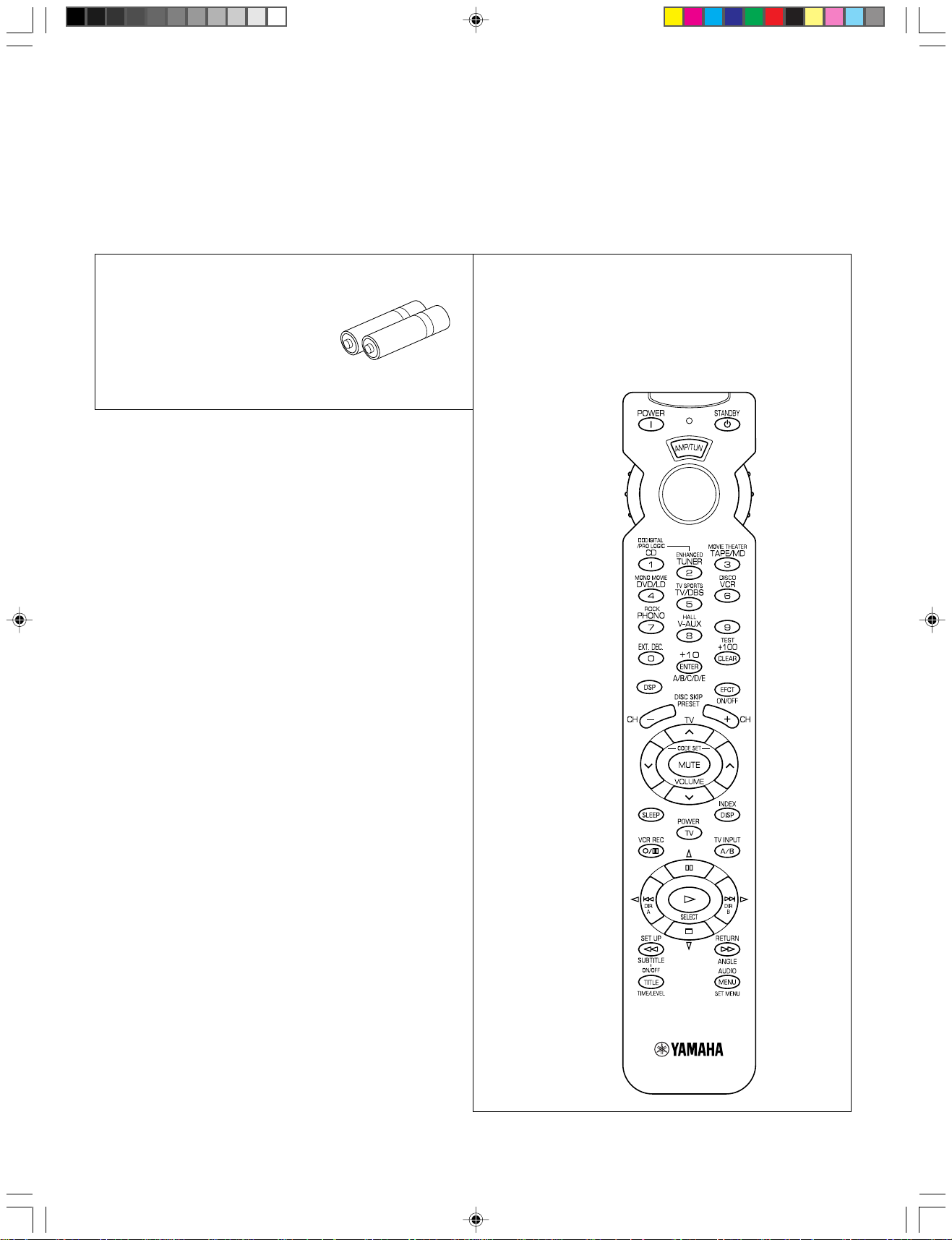
• Remote control transmitter
• Télécommande
• Fernbedienung
• Fjärrkontroll
• Telecomando
• Transmisor de control remoto
• Afstandsbediening
2
DSP-A595-1 3/25/99, 3:52 PM2
Page 3

FEATURES
English
● 5 Speaker Configuration
Main: 65 W + 65 W (8Ω) RMS Output
Power, 0.04% THD, 20 Hz – 20 kHz
Center: 65 W (8Ω) RMS Output
Po wer, 0.04% THD, 20 Hz – 20 kHz
Rear: 65 W + 65 W (8Ω) RMS Output
Po wer, 0.04% THD, 20 Hz – 20 kHz
● Digital Sound Field Processor
● Dolby Digital Decoder
● Dolby Pro Logic Surround Decoder
● CINEMA DSP: Theater-like Sound
Experience by the Combination of Dolby
Surround and YAMAHA DSP Technology
● 6-Channel External Decoder Input for DTS
● Automatic Input Balance Control for
Dolby Pro Logic Surround
● Test Tone Generator for Easier Speaker
Balance Adjustment
● Speaker Output Mode Changing
Capability
● Video Signal Input/Output Capability
(Including S Video Connections)
● SLEEP Timer
● Universal Remote Control
Transmitter with Preset Manufacturer
Codes
and other future formats
CONTENTS
SUPPLIED ACCESSORIES........................................... 2
FEA TURES .................................................................... 3
CAUTION ....................................................................... 4
●Introduction
FEATURES ON SOUND EFFECT.................................5
CONTROLS AND THEIR FUNCTIONS ......................... 7
●Preparation
SPEAKER SETUP ....................................................... 10
CONNECTIONS........................................................... 12
ADJUSTMENTS
BEFORE USING THIS UNIT .................................. 19
●Information about DSP
USING DIGITAL SOUND FIELD
PROCESSOR (DSP) .............................................. 29
●Advanced Information
ADJUSTMENTS
IN THE “SET MENU” MODE...................................35
●Remote Control Transmitter
REMOTE CONTROL TRANSMITTER......................... 37
SETUP CODES ........................................................... 42
NOTES ABOUT THE REMOTE CONTROL
TRANSMITTER ...................................................... 43
●Basic Oparation
BASIC OPERATIONS .................................................. 24
SETTING THE SLEEP TIMER..................................... 28
DSP-A595-1 3/25/99, 3:52 PM3
TROUBLESHOOTING ................................................. 44
SPECIFICA TIONS .......................................................46
LIST OF MANUFACTURER’S CODE........................ 311
3
Page 4
CAUTION : READ THIS BEFORE OPERATING YOUR UNIT.
1. To assure the finest performance, please read this manual
carefully. Keep it in a safe place for future reference.
2. Install this unit in a cool, dry, clean place – away from
windows, heat sources, sources of excessive vibration,
dust, moisture and cold. Avoid sources of humming
(transformers, motors). To prevent fire or electrical shock,
do not expose the unit to rain or water.
3. Never open the cabinet. If something drops into the set,
contact your dealer.
4. Do not use force on switches, controls or connection wires.
When moving the unit, first disconnect the power plug and
the wires connected to other equipment. Never pull the
wires themselves.
5. The openings on the unit cover assure proper ventilation of
the unit. If these openings are obstructed, the temperature
inside the unit will rise rapidly. Therefore, avoid placing
objects against these openings, and install the unit in a
well-ventilated area to prevent fire and damage.
<U.K. and Europe models>
Be sure to allow a space of at least 20 cm behind, 20 cm
on the both sides and 30 cm above the top panel of the unit
to prevent fire and damage.
6. The voltage used must be the same as that specified on
this unit. Using this unit with a higher voltage than specified is dangerous and may result in fire or other accidents.
YAMAHA will not be held responsible for any damage
resulting from use of this unit with a voltage other than
specified.
7. Digital signals generated by this unit may interfere with
other equipment such as tuners, receivers or TVs. Move
this unit farther away from such equipment if interference is
observed.
8. Always set the VOLUME control to “∞” before starting the
audio source play. Increase the volume gradually to an
appropriate level after playback has been started.
9. Do not attempt to clean the unit with chemical solvents; this
might damage the finish. Use a clean, dry cloth.
10. Be sure to read the “TROUBLESHOOTING” section
regarding common operating errors before concluding that
the unit is faulty.
11. When not planning to use this unit for long periods of time
(ie., vacation, etc.), disconnect the AC power plug from the
wall outlet.
12. To prevent lightning damage, disconnect the AC power
plug and disconnect the antenna cable when there is an
electrical storm.
13. Grounding or polarization – Precautions should be taken so
that the grounding or polarization of an appliance is not
defeated.
14. AC outlet
Do not connect audio equipment to the AC outlet on the
rear panel if that equipment requires more power than the
outlet is rated to provide.
15. Voltage Selector (China and General Models only)
The voltage selector on the rear panel of this unit must
be set for your local main voltage BEFORE plugging
into the AC main supply.
Voltages are 110/120/220/240 V AC, 50/60 Hz.
For U.K. customers
If the socket outlets in the home are not suitable for the plug
supplied with this appliance, it should be cut off and an appropriate 3 pin plug fitted. For details, refer to the instructions
described below.
Note: The plug severed from the mains lead must be destroyed, as a plug with bared flexible cord is hazardous if
engaged in a live socket outlet.
Special Instructions for U.K. Model
IMPORTANT
THE WIRES IN THE MAINS LEAD ARE COLOURED IN
ACCORDANCE WITH THE FOLLOWING CODE:
Blue: NEUTRAL
Brown: LIVE
As the colours of the wires in the main lead of this apparatus
may not correspond with the coloured markings identifying
the terminals in your plug, proceed as follows:
The wire which is coloured BLUE must be connected to the
terminal which is marked with the letter N or coloured
BLACK. The wire which is coloured BROWN must be
connected to the terminal which is marked with the letter L or
coloured RED. Make sure that neither core is connected to
the earth terminal of the three pin plug.
This unit is not disconnected from the AC power source as
long as it is connected to the wall outlet, even if this unit
itself is turned off. This state is called the standby mode. In
this state, this unit is designed to consume a very small
quantity of power.
4
DSP-A595-1 3/25/99, 3:52 PM4
Page 5

FEATURES ON SOUND EFFECT
English
This unit incorporates a sophisticated, multi-program digital
sound field processor. The processor allows you to electronically expand and change the shape of the audio sound field
from both audio and video sources, creating a theater-like
experience in your listening room. This unit has a total of 8
digital sound field processor (DSP) modes. You can create an
excellent audio sound field by selecting a suitable sound field
(this will, of course, depend on what you will be listening to),
and adding desired adjustments.
Digital Sound Field Processing
What is it that makes live music so good? Today’s advanced
sound reproduction technology lets you get extremely close to
the sound of a live performance, but chances are you’ll still
notice something missing, the acoustic environment of the live
concert hall. Extensive research into the exact nature of the
sonic reflections that create the ambience of a large hall has
made it possible for YAMAHA engineers to bring you this same
sound in your listening room, so you’ll feel all the sound of a
live concert.
Dolby Pro Logic Surround
This unit employs a Dolby Pro Logic Surround decoder similar
to professional Dolby Stereo decoders used in many movie
theaters. By using the Dolby Pro Logic Surround decoder, you
can experience the dramatic realism and impact of Dolby
Surround movie theater sound in your own home. Dolby Pro
Logic employs a four channel five speaker system. The Pro
Logic Surround system divides the input signal into four levels:
the left and right main channels, the center channel (used for
dialog), and the rear surround sound channels (used for sound
effects, background noise, and other ambient noises). The
center channel allows listeners seated in even less-than-ideal
positions to hear the dialog originating from the action on the
screen while experiencing good stereo imaging.
Dolby Digital
In addition, this unit incorporates a Dolby Pro Logic Surround
decoder and Dolby Digital decoder for multi-channel sound
reproduction of Dolby Surround encoded video sources. The
operation of the Dolby Pro Logic Surround or Dolby Digital
decoder can be controlled by selecting a corresponding DSP
program including combined operations of the YAMAHA DSP
and the Dolby Pro Logic Surround or Dolby Digital decoder.
Furthermore, our technicians, armed with sophisticated
measuring equipment, have even made it possible to capture
the acoustics of a variety of actual concert halls, theaters, etc.
from around the world, to allow you to accurately re-create any
one of these live performance environments, all in your home.
Dolby Surround is encoded on the sound track of pre-recorded
video tapes, laser discs, and some TV/cable broadcasts. When
you play a source encoded with Dolby Surround on this unit,
the Dolby Pro Logic Surround decoder decodes the signal and
distributes the surround-sound effects.
This Dolby Pro Logic Surround decoder employs a digital signal
processing system. This system improves the stability of sound
at each channel and crosstalk between channels, so that
positioning of sounds around the room is more accurate
compared with conventional analog signal processing systems.
In addition, this unit features a built-in automatic input balance
control. This always assures you the best performance without
manual adjustment.
The built-in Dolby Digital decoder leads you into a totally new
sound experiences.
Dolby Digital is a new generation of multi-channel digital audio
technology, or the newest spatial sound processing format
developed for 35 mm film-movies by employing a new kind of
low bit-rate audio coding.
Dolby Digital is a digital surround sound system that provides
completely independent multi-channel audio to consumers. In
multi-channel form, Dolby Digital provides five full range
channels in what is sometimes referred to as a “3/2” configuration: three front channels (left, center and right), plus two
surround channels. A sixth bass-only effect channel is also
provided for output of LFE (low frequency effect), or low bass
effects that are independent of other channels. This channel is
counted as 0.1, thus giving rise to the term 5.1 channels in
total.
DSP-A595-1 3/25/99, 3:52 PM5
Compared to Dolby Pro Logic that is referred to a “3/1” system
(left front, center, right front and just one surround channel),
Dolby Digital features two surround channels, called stereo or
split surrounds, each offering the same full range fidelity as the
three front channels.
Sound of wide dynamic range reproduced by the five full range
channels presents listeners much excitement that has never
been experienced before. Precise sound orientation by the
discrete digital sound processing expands realism that the
original movie possesses.
LD and DVD are home audio formats that could benefit from
Dolby Digital. In the near future, Dolby Digital will also be
applied to DBS, CATV and HDTV. The ongoing release of
Dolby Stereo Digital theatrical films now underway will provide
an immediate source of Dolby Digital encoded video software.
5
Page 6
Manufactured under license from Dolby Laboratories Licensing
Corporation. “Dolby”, “Pro Logic”, and the double-D symbol are
trademarks of Dolby Laboratories Licensing Corporation.
Copyright 1992 Dolby Laboratories, Inc. All rights reserved.
The following original functions make the surround-sound effect
of Dolby Digital become the most suitable for your audio
system and the listening conditions.
Dolby Surround + DSP (CINEMA DSP)
• Dynamic range (sound scale) of source can be changed
so that it will be suitable for the listening conditions.
• Output of low bass from any channel can be assigned to
either the MAIN SPEAKERS terminals or SUBWOOFER
terminal to maximize system performance.
• Output of LFE can be assigned to either the MAIN
SPEAKERS terminals or SUBWOOFER terminal to
maximize system performance.
Dolby Surround sound system shows its full ability in a large
movie theater, because movie sounds are originally designed to
be reproduced in a large movie theater using many speakers.
It is difficult to create a sound environment similar to that of a
movie theater in your listening room, because the room size,
materials of inside walls, the number of speakers, etc. of your
listening room is much different from those of a movie theater.
Dolby Pro Logic + 2 Digital Sound Fields
Digital sound fields are created on the presence side and the
rear surround side of the Dolby Pro Logic Surround-decoded
sound field respectively. They create a wide acoustic
environment and emphasize surround-effect in the room,
letting you feel much presence as if you are watching a
movie in a popular Dolby Stereo theater.
This combination is available when the sound field program
DOLBY PRO LOGIC ENHANCED/DOLBY DIGITAL
ENHANCED, 70 mm MOVIE THEATER/DIGITAL MOVIE
THEATER or TV SPORTS is selected, and the input signal of
source is analog, PCM audio or encoded with the Dolby
Digital in 2-channel.
YAMAHA DSP technology made it possible to present you with
nearly the same sound experience as that of a large movie
theater in your listening room by compensating for lack of
presence and dynamics in your listening room with its original
digital sound fields combined with Dolby Surround sound field.
CINEMA DSP
The YAMAHA “CINEMA DSP” logo indicates those programs
are created by the combination of Dolby Surround and
YAMAHA DSP technology.
Dolby Digital + 3 Digital Sound Fields
Digital sound fields are created on the presence side and the
independent left and right surround sides of the Dolby Digitaldecoded sound field respectively. They create a wide
acoustic environment and much surround effect in the room
without losing high channel separation. With wide dynamic
range of Dolby Digital sound, this sound field combination lets
you feel as if you are watching a movie in the newest Dolby
Stereo Digital theater. This will be the most ideal home
theater sound at the present time.
This combination is available when the sound field program
DOLBY PRO LOGIC ENHANCED/DOLBY DIGITAL
ENHANCED, 70 mm MOVIE THEATER/DIGITAL MOVIE
THEATER or TV SPORTS is selected, and the input signal of
source is encoded with the Dolby Digital (except in 2-channel).
6
DSP-A595-1 3/25/99, 3:52 PM6
Page 7
CONTROLS AND THEIR FUNCTIONS
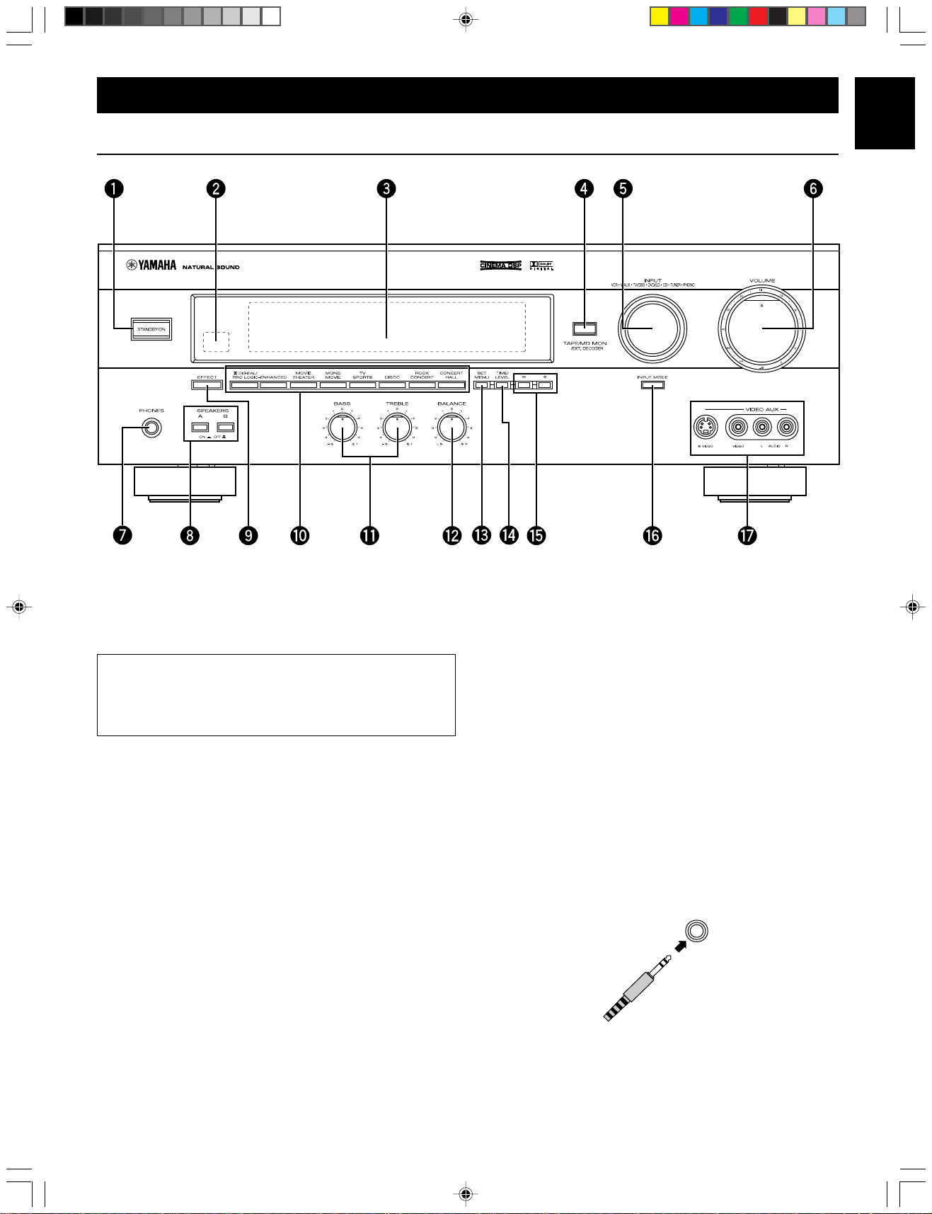
FRONT PANEL
English
1 STANDBY/ON
Press this switch to turn the power of this unit on. Press it
again to turn this unit into the standby mode.
Standby mode
In this state, this unit consumes a very small quantity of
power to receive infrared-signals from the remote control
transmitter.
2 Remote control sensor
Receives signals from the remote control transmitter.
3 Display
Shows various information. (For details, refer to page 9.)
4 TAPE/MD MON / EXT. DECODER
Press this button to play a tape or an MD. The “TAPE/MD
MON” indicator lights up on the display.
When you press the button next, the “TAPE/MD MON” indicator
goes off and “EXT. DECDR” appears on the display and you
can play the signal connected to the EXTERNAL DECODER
INPUT terminals.
5 INPUT
Turn this selector to select the program source (VCR, VIDEO
AUX, TV/DBS, DVD/LD, CD, TUNER, PHONO) to listen to or
watch.
The name of the selected program source appears on the
display.
6 VOLUME
This control is used to raise or lower the volume level.
7 PHONES jack
When you use headphones, connect the headphones to the
PHONES jack. You can listen to the sound to be output from
the main speakers through headphones.
When using headphones only, set both SPEAKERS A and B to
the OFF position and switch off the digital sound field processor
(so that no DSP program name appears on the display) by
pressing EFFECT.
PHONES
DSP-A595-1 3/25/99, 3:53 PM7
7
Page 8

8 SPEAKERS
Set A or B (or both A and B) to the ON position for the main
speaker system (connected to this unit) you will use. Set it (or
them) for the main speaker system you will not use to the OFF
position.
9 EFFECT
Switches on and off the output from the center and rear
speakers so that the sound becomes normal 2-channel.
* Even if the output from the center and rear speakers is off,
when the Dolby Digital is decoded, the signals at all channels
are distributed to the main channels and output from the main
speakers.
w BALANCE
This control is effective only for the sound from the main
speakers.
Adjusts the balance of the output volume to the left and right
speakers to compensate for sound imbalance caused by
speaker location or listening room conditions.
e SET MENU
Press this button to select functions in the SET MENU mode.
r TIME/LEVEL
Press this button to select the setting of delay time or speaker
output levels in the TIME/LEVEL mode.
0 PROGRAM selector
Press these buttons to select the DSP program.
The name of the selected program appears on the display.
q Tone controls
These controls are effective only for the sound from the main
speakers.
BASS
Used to increase or decrease the low frequency response. The
“0” position produces flat response.
TREBLE
Used to increase or decrease the high frequency response.
The “0” position produces flat response.
t +/–
These buttons are used to adjust settings of the SET MENU
mode and the TIME/LEVEL mode. In the TIME/LEVEL mode,
press + to increase delay time or speaker output levels. Press
– to decrease delay time or speaker output levels.
y INPUT MODE
Switches the DVD/LD and TV/DBS input signal mode (AUTO/
ANALOG).
u VIDEO AUX terminals
Connect an auxiliary video or audio input source unit such as a
camcorder to these terminals. If the connected video unit has a
S video output terminal, connect it to the S VIDEO terminal to
obtain a high resolution picture. The source connected to these
terminals can be selected by INPUT.
8
DSP-A595-1 3/25/99, 3:53 PM8
Page 9
DISPLAY PANEL
English
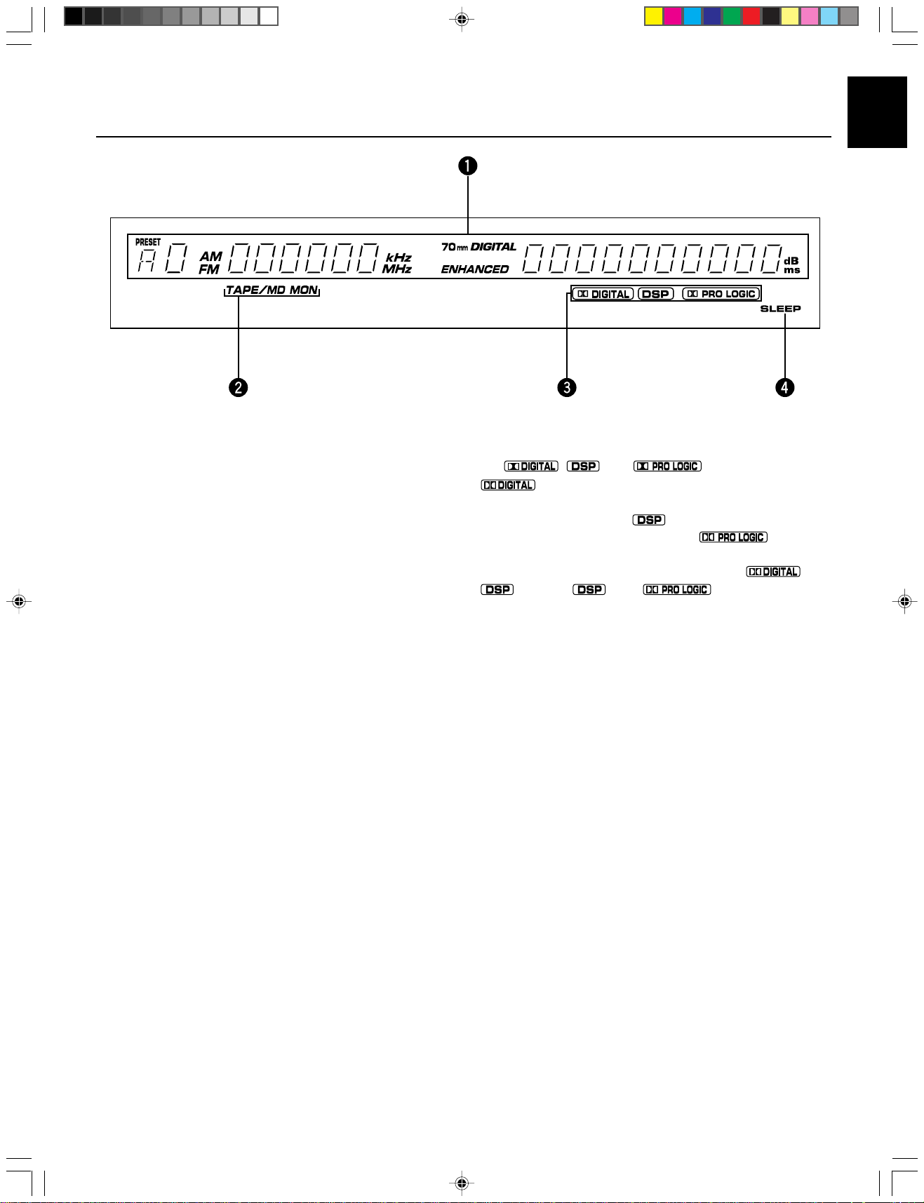
1 Multi-information display
Displays various information, for example name of selected
DSP program and name of selected input source.
2 TAPE/MD MON indicator
Lights up when the tape deck (or MD recorder etc.) is selected as
the input source by pressing T APE/MD MON / EXT. DECODER
on the front panel or T APE/MD on the remote control transmitter.
3 , and indicators
“
on and the signals of selected source encoded with the Dolby
Digital is not in 2-channel. “ ” lights up when the built-in
digital sound field processor is on, and “
when the built-in Dolby Pro Logic Surround decoder is on.
Depending on the selected DSP program, both “ ” and
“ ”, or both “ ” and “ ” will light up.
” lights up when the built-in Dolby Digital decoder is
” lights up
4 SLEEP indicator
Lights up while the built-in SLEEP timer is functioning.
DSP-A595-1 3/25/99, 3:53 PM9
9
Page 10

SPEAKERS TO BE USED
SPEAKER SETUP
This unit is designed to provide the best sound-field quality with
a 5-speaker configuration, using main speakers, rear speakers
and a center speaker.
The main speakers are used for the main source sound plus
the effect sounds. They will probably be the speakers from
your present stereo system. The rear speakers are used for
the effect and surround sounds, and the center speaker is for
the center sounds (dialog, vocals, etc.). If for some reason it is
not practical to use a center speaker, you can do without it.
Best results, however, are obtained with the full system.
The main speakers should be high performance models and
have enough power handling capacity to accept the maximum
output of your audio system.
Other speakers do not have to be equal to the main speakers.
For precise sound localization, however, it is ideal to use high
performance models that can reproduce sounds in the full
range for the center speaker and the rear speakers.
SPEAKER CONFIGURATION
5-Speaker Configuration
Use of a subwoofer expands your sound field
It is also possible to further expand your system with the
addition of a subwoofer and amplifier. The use of a subwoofer
is effective not only for reinforcing bass frequencies from any or
all channels, but also for reproducing the LFE (low frequency
effect) sound with high fidelity when playing back a source with
the Dolby Digital decoded. You may wish to choose the
convenience of a YAMAHA Active Servo Processing Subwoofer
System, which has its own built-in power amplifier.
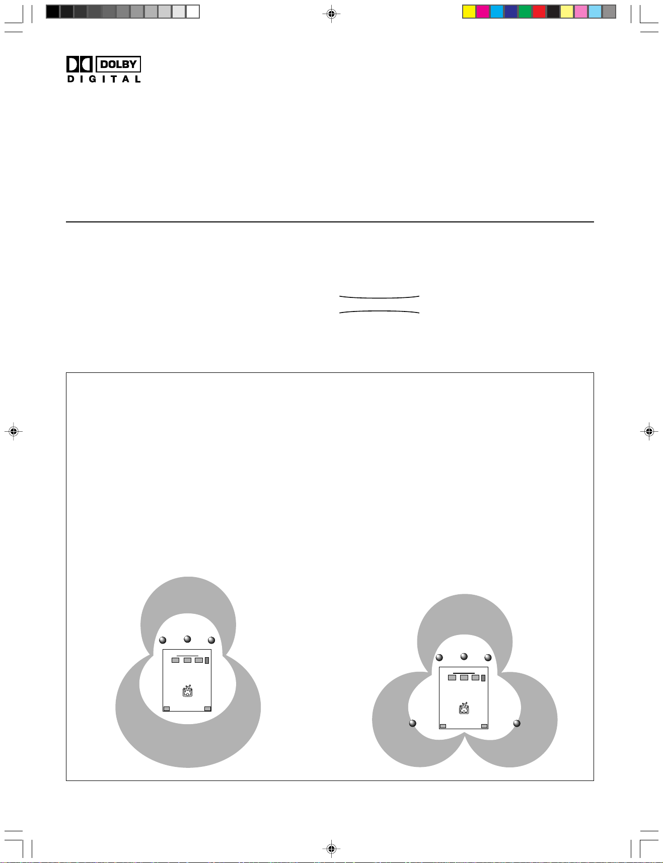
4-Speaker Configuration
This configuration is the most effective and recommended one.
When playing back a source using the DSP program,
DOLBY PRO LOGIC/DOLBY DIGITAL, DOLBY PRO LOGIC
ENHANCED/DOLBY DIGITAL ENHANCED, 70 mm MOVIE
THEATER/DIGITAL MOVIE THEATER, MONO MOVIE or TV
SPORTS, or when playing back a source which contains
center-channel signals (dialog, vocals, etc.) using any DSP
program with the Dolby Digital decoded, conversations will be
output from the center speaker and the ambience will be
excellent.
Note: Set the CNTR (CENTER SPEAKER) mode to the
“LARGE” or “SMALL” position. (For details, see
page 19.)
Main L Center Main R
Dialog
Surround sound
Surround sound
The center speaker is not used in this configuration. When
playing back a source using the DSP program, DOLBY PRO
LOGIC/DOLBY DIGITAL, DOLBY PRO LOGIC ENHANCED/
DOLBY DIGITAL ENHANCED, 70 mm MOVIE THEATER/
DIGITAL MOVIE THEATER, MONO MO VIE or TV SPORTS, or
when playing back a source which contains center-channel
signals (dialog, vocals, etc.) using any DSP program with the
Dolby Digital decoded, the center sound is output from the left
and the right main speakers. However, the sound effect of
other programs will be the same as that of the 5-speaker
configuration.
Note: Be sure to set the CNTR (CENTER SPEAKER) mode to
the “NONE” position. (For details, see page 19.)
Main L Main R
Dialog
Surround sound
Surround sound
Rear L
10
DSP-A595-2 3/25/99, 3:53 PM10
Rear R
Rear L Rear R
Page 11

SPEAKER PLACEMENT
When you place the speakers, refer to the following diagram:
English
Main: The position of your present stereo speaker
system.
Rear: Behind your listening position, facing slightly
inward. Nearly 1.8 m (approx. 6 feet) up from the
floor.
Center: Precisely between the main speakers. (To avoid
interference with TV sets, use a magnetically
shielded speaker.)
Subwoofer: The position of the subwoofer is not so critical
because low bass tones are not highly directional.
Main speaker
Subwoofer
Center speaker Rear speaker
DSP-A595-2 3/25/99, 3:53 PM11
11
Page 12

CONNECTIONS
Never plug in this unit and other components until all connections are completed.
CONNECTIONS WITH OTHER COMPONENTS
When making connections between this unit and other components, be sure all connections are made correctly, that is to say L
(left) to L, R (right) to R, “+” to “+” and “–” to “–”. Also, refer to the owner’s manual for each component to be connected to this unit.
* If you have YAMAHA components numbered as !, @, #, $, etc. on the rear panel, connections can be made easily by making
sure to connect the output (or input) terminals of each component to the same-numbered terminals of this unit.
Turntable Monitor TV
DVD player, LD player, etc.
(Eupore model)
CD player Tape deck,
, : See the next page.
Tuner
12
DSP-A595-2 3/25/99, 3:53 PM12
MD recorder, etc.
T o AC outlet
TV/DBS tuner VCR
(Video cassette recorder)
Page 13

English
SWITCHED AC OUTLET(S)
(China and General models) .............. 3 SWITCHED OUTLETS
(Europe models) ................................ 2 SWITCHED OUTLETS
(U.K. model) ..........................................1 SWITCHED OUTLET
GND terminal (For turntable use)
Connecting the ground wire of the turntable to the GND
terminal will normally minimize hum, but in some cases better
results may be obtained with the ground wire disconnected.
Use these to connect the power cords from your components to
this unit.
The power to the SWITCHED outlets is controlled by this unit’s
STANDBY/ON or the provided remote control transmitter’s
POWER and STANDBY. These outlets will supply power to
any component whenever this unit is turned on.
The maximum power (total power consumption of components)
that can be connected to the SWITCHED AC OUTLET(S) is
100 watts.
CONNECTING TO AN EXTERNAL DECODER
When using the DTS or other decoder with 6-channel discrete outputs, connect the 6CH DISCRETE OUTPUT terminals of the
decoder to the EXTERNAL DECODER INPUT terminals of this unit.
DTS or other decoder with 6-channel
discrete outputs
L
R
L
R
(Eupore model)
DSP-A595-2 3/25/99, 3:53 PM13
DVD player, LD player or other
unit with digital outputs
13
Page 14

CONNECTING TO DIGITAL (COAXIAL AND/OR OPTICAL) TERMINALS
If your DVD (LD) player, TV/DBS tuner, etc. are equipped with
coaxial or optical digital audio signal output terminals, they can
be connected to this unit’s COAXIAL and/or OPTICAL digital
signal input terminals.
To make a connection between optical digital audio signal
terminals, remove the cover from each terminal, and then
connect them by using a commercially available optical fiber
cable that conforms to EIAJ standards. Other cables might not
function correctly.
Even if you connect an audio/video unit to the COAXIAL (or
OPTICAL) terminal of this unit, you must keep the unit connected with the same named analog audio signal terminals of
this unit, because digital signal cannot be recorded by a tape
deck or VCR connected to this unit. You can switch the
selection of input signals between “digital” and “analog” easily.
(See page 26 for details.)
DVD or LD player TV/DBS tuner
Notes
• When connecting an audio/video unit to both of the digital
and analog terminals of this unit, make sure to connect to
both terminals of the same name.
• Be sure to attach the covers when the OPTICAL terminals
are not being used, in order to protect the terminals from
dust.
• The input signal from the DVD/LD input terminals is selected
in the following order of priority.
(input mode: AUTO position)
1 COAXIAL terminal
2 OPTICAL terminal
3 ANALOG terminal
• All digital audio signal input terminals are applicable to the
sampling frequency of 32 kHz, 44.1 kHz and 48 kHz.
(Eupore model)
14
DSP-A595-2 3/25/99, 3:53 PM14
Page 15

CONNECTING TO S VIDEO TERMINALS
English
If you have a VCR and a monitor equipped with “S” (highresolution) video terminals, those terminals can be connected
to this unit’s S VIDEO terminals. Connect the VCR’s “S” video
input and output terminals to this unit’s S VIDEO VCR OUT and
IN terminals respectively, and connect the monitor’s “S” video
input terminal to this unit’s S VIDEO MONITOR OUT terminal.
Otherwise, connect the VCR’s composite video terminals to this
unit’s composite VIDEO terminals, and connect the monitor’s
composite video input terminal to this unit’s composite
MONITOR OUT terminal.
Note
If video signals are sent to both S VIDEO input and composite input terminals, the signals will be sent to their
respective output terminals.
Monitor TV
VCR
CONNECTING TO VIDEO AUX TERMINALS (ON THE FRONT PANEL)
These terminals are used to connect any video input source, such as a camcorder, to this unit.
Camcorder
DSP-A595-2 3/25/99, 3:53 PM15
15
Page 16

CONNECTING SPEAKERS
Main speakers A Main speakers B
Right
Subwoofer system
Left
(Eupore model)
Center speaker
Right Left
Left
Rear speakers
Right
Note
Use speakers with the specified impedance shown on the
rear panel of this unit.
Note on main speaker connections:
One or two speaker systems can be connected to this unit. If
you use only one speaker system, connect it to either the
SPEAKERS A or B terminals.
16
Note on a subwoofer connection:
You may wish to add a subwoofer to reinforce low frequencies
or to output low bass sound from the subwoofer channel.
If you have a subwoofer with built-in amplifier, including the
YAMAHA Active Servo Processing Subwoofer System, connect
the SUBWOOFER OUTPUT terminal of this unit to the input
terminal of the subwoofer system.
If you have an amplifier and a subwoofer, connect the
SUBWOOFER OUTPUT terminal of this unit to the input
terminal of the subwoofer amplifier, and then connect the
speaker terminals of the subwoofer amplifier to the subwoofer.
Note on center speaker connection:
Center speaker can be connected to this unit. Place it on or
under the TV.
DSP-A595-2 3/25/99, 3:53 PM16
Page 17

How to connect
Connect the SPEAKERS terminals to your speakers with wire of the proper gauge, cut as short as possible. If the connections are
faulty, no sound will be heard from the speakers. Make sure that the polarity of the speaker wires is correct, that is the + and –
markings are observed. If these wires are reversed, the sound will be unnatural and lack bass.
Caution
Do not let the bare speaker wires touch each other and do not let them touch any metal part of this unit. This could
damage this unit and/or speakers.
English
For connecting to the MAIN SPEAKERS
terminals
Red: positive (+)
Black: negative (–)
2
1
3
Banana plug connections are also possible (except for U.K. and
Europe models). Simply insert the banana plug connector into
the corresponding terminal.
1 Unscrew the knob.
2 Insert the bare wire.
[Remove approx. 5 mm
(1/4”) insulation from the
speaker wires.]
3 Tighten the knob and
secure the wire.
For connecting to the REAR and CENTER
SPEAKERS terminals
Red: positive (+)
Black: negative (–)
1
3
2
1 Press the tab.
2 Insert the bare wire.
[Remove approx. 5 mm
(1/4”) insulation from
the speaker wires.]
3 Release the tab and
secure the wire.
OUTPUT TERMINALS (FOR DRIVING SPEAKERS WITH EXTERNAL AMPLIFIERS)
(MAIN, CENTER and REAR OUTPUT terminals are provided for U.K. and Europe models only.)
MAIN OUTPUT terminals
These terminals are for the main channel line output. There is
no connection to these terminals when you use the built-in
amplifier.
However, if you drive the main speakers with an external stereo
power amplifier, connect the input terminals of the external
amplifier (MAIN IN or AUX terminals of a power amplifier or an
integrated amplifier) to these terminals.
* Output signals from the MAIN OUTPUT terminals are
affected by the use of BASS, TREBLE, and B ALANCE.
17
DSP-A595-2 3/25/99, 3:53 PM17
Page 18

CENTER OUTPUT terminals
These terminals are for the center channel line output. There is
no connection to these terminals when you use the built-in
amplifier.
However, if you drive a center speaker with an external power
amplifier, connect the input terminal of the external amplifier to
this terminal.
If you are placing two center speakers on each side of the TV,
use two amplifiers and connect each amplifier to one of the two
CENTER OUTPUT terminals. Then connect the center
speakers to the amplifiers.
REAR (SURROUND) OUTPUT terminals
These terminals are for the rear channel line output. There is
no connection to these terminals when you use the built-in
amplifier.
However, if you drive the rear speakers with an external stereo
power amplifier, connect the input terminals of the external
amplifier (MAIN IN or AUX terminals of a power amplifier or an
integrated amplifier) to these terminals.
IMPEDANCE SELECTOR SWITCH
WARNING
Do not change the IMPEDANCE SELECTOR switch setting
while the power of this unit is on, otherwise this unit may be
damaged.
SUBWOOFER OUTPUT terminal
This terminal is for connecting to the input terminal of an
amplifier for driving a subwoofer.
When the input signals to this unit are in normal 2-channel
stereo, this terminal outputs only frequencies below 90 Hz from
the main and center channels. When discrete signals are input
to this unit and are selected as the input source, this terminal
outputs signals from the subwoofer channel.
Note
Output levels of signals from all of these terminals are
adjusted by the use of VOLUME on the front panel or
VOLUME (
Select the position whose requirements your speaker system
meets.
(Upper position)
) on the remote control transmitter.
IF THIS UNIT FAILS TO TURN ON WHEN THE STANDBY/
ON SWITCH IS PRESSED, the IMPEDANCE SELECTOR
switch may not be fully set to either end. If so, set the switch
to either end fully.
IMPEDANCE SELECTOR
(Europe model)
Main: If you use one pair of main speakers, the impedance of
each speaker must be 4Ω or higher.
If you use two pairs of main speakers, the impedance
of each speaker must be 8Ω or higher.
Center: The impedance of the speaker must be 6Ω or higher.
Rear: The impedance of each speaker must be 6Ω or higher.
(Lower position)
Main: If you use one pair of main speakers, the impedance of
each speaker must be 8Ω or higher.
If you use two pairs of main speakers, the impedance
of each speaker must be 16Ω or higher.
Center: The impedance of the speaker must be 8Ω or higher.
Rear: The impedance of each speaker must be 8Ω or higher.
18
DSP-A595-2 3/25/99, 3:53 PM18
Page 19

ADJUSTMENTS BEFORE USING THIS UNIT
SELECTING THE OUTPUT MODES
This unit provides you the following five functions to determine the method of distributing output signals to speakers suitable for
your audio system. When speaker connections are all completed, select a proper position on each function to make the best use of
your speaker system. (See “ADJUSTMENTS IN THE ‘SET MENU’ MODE” on page 35)
1. CNTR (CENTER SPEAKER) 2. REAR (REAR SPEAKER) 3. MAIN (MAIN SPEAKER)
4. BASS (LFE/BASS OUT) 5. M.LVL (MAIN LEVEL)
DESCRIPTION OF EACH FUNCTION
English
1. CNTR (CENTER SPEAKER)
Choices: LARGE/SMALL/NONE
Preset position: LARGE
LARGE: Select this position when your center speaker is
approximately the same size as the main speakers.
SMALL: Select this position when you use a center speaker
that is smaller than the main speakers.
In this position, low bass signals (below 90 Hz) at the
center channel are output from the main speakers (or
the SUBWOOFER OUTPUT terminal if the SMALL
position is selected on “3. MAIN” and the SW position
is selected on “4. BASS”).
NONE: Select this position when you do not have a center
speaker. The center channel sound will be output
from the left and right main speakers.
2. REAR (REAR SPEAKER)
Choices: LARGE/SMALL
Preset position: LARGE
LARGE: Select this position if your rear speakers have a high
ability for bass reproduction, or a subwoofer is
connected to the rear speaker in parallel.
In this position, full range signals are output from the
rear speakers.
SMALL: Select this position if your rear speakers do not have
a high ability for bass reproduction.
In this position, low bass signals (below 90 Hz) at the
rear channels are output from the SUBWOOFER
OUTPUT terminal (or the main speakers if the MAIN
position is selected on “4. BASS”).
3. MAIN (MAIN SPEAKER)
Choices: LARGE/SMALL
Preset position: LARGE
LARGE: Select this position if your main speakers have a
high ability for bass reproduction.
In this position, full range signals present at the main
channels are output from the main speakers.
SMALL: Select this position if your main speakers do not
have a high ability for bass reproduction. However, if
your system does not include a subwoofer, do not
select this position.
In this position, low bass signals (below 90 Hz) at the
main channels are output from the SUBWOOFER
OUTPUT terminal if the SW or BOTH position is
selected on “4. BASS”.
4. BASS (LFE/BASS OUT)
Choices: SW/MAIN/BOTH
Preset position: SW
MAIN: Select this position if your system does not include a
subwoofer.
In this position, full range signals present at the main
channels, signals from the LFE channel and other
low bass signals that are selected on “1. CNTR” to
“3. MAIN” to be distributed from other channels are
output from the main speakers.
SW/BOTH:
Select either the SW or BOTH position if your
system includes a subwoofer.
In either position, signals at LFE channel and other
low bass signals that are selected on “1. CNTR” to
“3. MAIN” to be distributed from other channels are
output from the SUBWOOFER OUTPUT terminal.
When the LARGE position is selected on “3. MAIN”,
in the SW position, no signal is distributed from the
main channels to the SUBWOOFER OUTPUT
terminal, however in the BOTH position, low bass
signals from the main channels are output to both of
the main speakers and the SUBWOOFER OUTPUT
terminal.
5. M.LVL (MAIN LEVEL)
Choices: NORMAL (NRML)/–10 dB
Preset position: NORMAL (NRML)
NORMAL (NRML):
Normally select this position.
–10 dB: Select this position if the sound output from the main
speakers is too loud and cannot be balanced with
the sound output from the center and rear speakers.
In this position, the sound output from the main
speakers is attenuated.
DSP-A595-2 3/25/99, 3:53 PM19
19
Page 20

ADJUSTING METHOD
Operations should be made while watching the information on this unit’s display.
1 2 3
1
3
2
If you are using the remote control transmitter, set the
SELECTOR DIAL to the AMP/TUN or DSP position on the
remote control transmitter.
or
1 Turn the power on.
Front panel Remote control
or
2 Press SET MENU once or more to select the title
“1. CNTR” (so that “CNTR” appears on the display).
Front panel Remote control
or
3 Press + or – once or more to select the position you
want.
Front panel Remote control
or
Changes.
4 Repeat steps 2 and 3 to change selections on
“2. REAR”, “3. MAIN”, “4. BASS” and/or “5. M.LVL” in
the same way.
* After pressing SET MENU once on the remote control
transmitter, you can also select the title by pressing
(Pressing
goes back one selection.)
Appears.
20
DSP-A595-2 3/25/99, 3:53 PM20
.
Page 21

SPEAKER BALANCE ADJUSTMENT
This procedure lets you adjust the sound output level balance between the main, center and rear speakers using the built-in test
tone generator. When this adjustment is performed, the sound output level heard at the listening position will be the same from
each speaker. This is important for the best performance of the digital sound field processor, the Dolby Digital decoder and the
Dolby Pro Logic Surround decoder.
The adjustment of each speaker output level should be done at your listening position with the remote control transmitter.
After completing the adjustment of the output level for each speaker, use VOLUME (
ter at your listening position to check if the adjustments are satisfactory.
) on the remote control transmit-
English
2 1
3
Set the SELECTOR DIAL to the AMP/TUN or DSP position
on the remote control transmitter.
4,74
or
2
2 Turn the power on.
Front panel Remote control
5,9
6
8
or
1 Set VOLUME to the “∞” position.
Front panel
3 Select the main speakers to be used.
Front panel
* If you use two main speaker systems, press both A and B.
21
DSP-A595-2 3/25/99, 3:53 PM21
Page 22

4 Set BASS, TREBLE and BALANCE to the “0” position.
6 Turn up the volume.
Front panel
5 Press TEST (so that “TEST LEFT” appears on the
display).
Remote control
Appears.
Remote control
You will hear a test tone (like pink noise) from the left main
speaker, then the center speaker, then the right main
speaker, then the right rear speaker, and then the left rear
speaker, for about two seconds each. The display changes
as shown below.
Main (L)
Center
Main (R)
Rear (R)
Rear (L)
* If the function “1. CNTR” in the SET MENU mode is set to
the NONE position, you will hear the center channel test
tone from the left and right main speakers.
7 Adjust BALANCE so that the sound output level of the
left main speaker and the right main speaker is the
same.
Front panel
22
DSP-A595-2 3/25/99, 3:53 PM22
Page 23

8 Adjust the sound output levels of the center speaker
and the rear speakers so that they become almost as
same as that of the main speakers.
Remote control
a) Press or once or more so that “CENTER”, “R SUR.”
or “L SUR.” appears on the display.
* Select “CENTER” to adjust the output level of the
center speaker and select “R SUR.” or “L SUR.” to
adjust the output level of the rear speakers.
Remote control
Notes
• Once you have completed these adjustments, you can adjust
the overall sound level on your audio system by using
VOLUME (or VOLUME (
transmitter) only.
• If you use external power amplifiers, you may also use their
volume controls to achieve the proper balance.
• If the function “1. CNTR” in the SET MENU mode is set to the
NONE position, the sound output level of the center speaker
cannot be adjusted in step 8. The center sound is automatically output from the left and right main speakers.
• If there is insufficient sound output from the center and rear
speakers, you may decrease the main speaker output level
by setting “5. M.LVL” to “–10 dB”.
) on the remote control
English
b) Adjust the level.
* Pressing
* While adjusting, the test tone is fixed on the selected
speaker.
raises and lowers the level.
Remote control
9 Press TEST once more to cancel the test tone.
Remote control
“TEST” disappears.
DSP-A595-2 3/25/99, 3:53 PM23
23
Page 24

TO PLAY A SOURCE
BASIC OPERATIONS
2
3 1,7
2
3,4
7
5 4
Notes
• Set the SELECTOR DIAL to the AMP/TUN position on the remote control transmitter .
• To operate the tuner, CD player, DVD/LD player, tape deck, MD recorder, or other components using this remote control transmitter, set the SELECTOR DIAL to the component to be used. (See “SETUP CODES” on page 42.)
1 Set VOLUME to the “∞” position.
Front panel
3 Select the desired input source by using INPUT.
(For video sources, turn the TV/monitor ON.)
See page 26 if you are using an external decoder or
playing a tape or an MD.
2 Turn the power on.
Front panel Remote control
Front panel Remote control
or
or
The name of the selected input source will appear on the
display.
24
DSP-A595-3 3/25/99, 3:53 PM24
Page 25

English
4 For the DVD/LD or TV/DBS source, the current input
mode is also shown.
* To change the input mode for the DVD/LD or TV/DBS
source, press INPUT MODE (or the button that you
have pressed to select the input source in step 3 on
the remote control transmitter) once or more until the
desired input mode (AUTO or ANALOG) is shown on
the display. (See page 26 for details on switching the
input mode.)
Front panel Remote control
or
Input mode
8 If desired, adjust BASS, TREBLE, BALANCE, etc.
(see below) and use the digital sound field processor.
(see page 29.)
Selecting the SPEAKER system
Because one or two speaker systems (as main speakers) can
be connected to this unit, SPEAKERS allow you to select
speaker system A or B, or both at once.
Adjusting the BALANCE control
Adjust the balance of the output volume from the left and right
speakers to compensate for sound imbalances caused by
speaker location or listening room conditions.
5 Select the main speakers to be used.
Front panel
* If you use two main speaker systems, press both A and B.
6 Play the source.
7 Adjust the volume to the desired output level.
Front panel Remote control
or
Note
This control is effective only for the sound from the main
speakers.
Adjusting the BASS and TREBLE controls
BASS: Turn this clockwise to increase (or counter-clockwise
to decrease) the low frequency response.
TREBLE
Note
These controls are effective only for the sound from the main
speakers.
: Turn this clockwise to increase (or counter-clockwise
to decrease) the high frequency response.
DSP-A595-3 3/25/99, 3:53 PM25
25
Page 26

To play a tape or an MD
Press TAPE/MD MON / EXT. DECODER so that the “TAPE/MD
MON” indicator lights up on the display, then play the tape or
MD.
Front panel Remote control
or
To stop playing the tape or MD, press TAPE/MD MON / EXT.
DECODER twice so that the “TAPE/MD MON” indicator and
“EXT. DECDR” disappear from the display and the play stops
(or press TAPE/MD once on the remote control transmitter).
To use a decoder connected to the EXTERNAL
DECODER INPUT terminals
Press TAPE/MD MON / EXT. DECODER once or more so that
the “EXT. DECDR” appears on the display.
Start the play by operating the DTS or other external decoder,
DVD player or LD player.
Front panel Remote control
or
To stop playing, press TAPE/MD MON / EXT. DECODER once
so that “EXT. DECDR” disappears from the display and the play
stops (or press EXT. DEC. on the remote control transmitter).
When you finish using this unit
Press STANDBY/ON on the front panel again or STANDBY on
the remote control transmitter to turn this unit into the standby
mode.
Notes on using INPUT
• By using INPUT, you can to select the program sources
connected to the input terminals on the rear panel.
• To play a video source connected to the VIDEO AUX
terminals on the front panel, set INPUT to the VIDEO AUX
position.
• The audio source selected by INPUT will not be played if the
“TAPE/MD MON” indicator lights up or if “EXT. DECDR” is
displayed.
• If you select INPUT for a video source without canceling the
selection of T APE/MD MON / EXT. DECODER on the front
panel (or, TAPE/MD or EXT. DEC. on the remote control
transmitter), the playback result will be the video image from
the video source and the sound from the input source
selected by T APE/MD MON / EXT. DECODER on the front
panel (or, TAPE/MD or EXT. DEC. on the remote control
transmitter).
• Once you play a video source, its video image will not be
interrupted even if INPUT for an audio source is selected.
• When you select an input source by using INPUT, the DSP
program (or no DSP program) that was used when the same
input source was selected the last time, will be automatically
recalled.
Switching the input mode
(for DVD/LD and TV/DBS)
This unit allows you to switch the input mode only for sources
connected to the DVD/LD and TV/DBS input terminals (on the
rear panel of this unit) that input two or three types of signals.
The following two input modes are provided.
AUTO: For the source connected to the DVD/LD input
terminals:
This mode is automatically selected when you turn the
power of this unit on. In this mode, input signal is
automatically selected in the following order of priority.
1. Digital input signal from the COAXIAL terminal
2. Digital input signal from the OPTICAL terminal
3. Analog input signal
For the source connected to the TV/DBS input
terminals:
This mode is selected when you turn the power of this
unit on if the AUTO position is selected on “10. INPUT”
in the SET MENU mode. (For details, see page 36.)
In this mode, input signal is automatically selected in
the following order of priority.
1. Digital input signal from the OPTICAL terminal
2. Analog input signal
ANALOG:
In this mode, only analog input signal is selected even
if a digital signal is input at the same time.
Select this mode when you want to use the analog
input signal instead of the digital input signal.
Notes on input mode selection
• To playback a source with the Dolby Digital-decoded, set the
input mode to AUTO.
• For the TV/DBS source only, the input mode selected on the
function “10. INPUT” in the SET MENU mode is effective
when you turn the power of this unit on.
• When you want to enjoy a source which has normal
2-channel signals with a Dolby Pro Logic Surround program,
select the ANALOG mode.
• In the AUTO mode, there may be a case depending on some
LD players or DVD players that when you make a search on
a source encoded with the Dolby Digital during the play and
then the play is restored, sound output is interrupted for a
moment because the digital input signal is selected again.
26
DSP-A595-3 3/25/99, 3:53 PM26
Page 27

TO RECORD A SOURCE TO TAPE OR MD
2
1,4
4 1 2
English
1 Select the source to be recorded.
Front panel Remote control
or
2 Play the source and then turn VOLUME up to confirm
the input source.
Front panel Remote control
or
3 Begin recording on the tape deck, MD recorder or VCR
connected to this unit.
4 When the tape deck or MD recorder is used for
recording, you can monitor the sounds being recorded
by pressing TAPE/MD MON / EXT. DECODER so that
the “TAPE/MD MON” indicator lights up on the display.
Front panel Remote control
or
Notes
• The settings of DSP and VOLUME, BASS, TREBLE and
BALANCE have no effect on the material being recorded.
• Composite video and S video signals pass independently
through this unit’s video circuits. Therefore, when recording
or dubbing video signals, if your video source unit is connected to provide only an S video (or only a composite video)
signal, you can record only an S video (or only a composite
video) signal on your VCR.
• A source that is connected to this unit through digital
terminals only cannot be recorded by a tape deck or VCR
connected to this unit.
• Please check the copyright laws in your country to record
from records, compact discs, radio, etc. Recording of
copyright material may infringe copyright laws.
If you watch a video software that uses scrambled or
encoded signals to prevent it from being dubbed, there may
be a case that the picture itself will be affected by those
signals.
DSP-A595-3 3/25/99, 3:53 PM27
27
Page 28

SETTING THE SLEEP TIMER
If you use the SLEEP timer of this unit, you can make this unit automatically switch to the standby mode. When you are going to
sleep while enjoying a broadcast or other desired input source, this timer function is useful. The SLEEP timer can be controlled
only with the remote control transmitter.
Notes
• To set the SLEEP timer for this unit, set the SELECTOR DIAL to a position other than the TV postition. To set the SLEEP timer
for your TV, set the SELECTOR DIAL to the TV position.
• The components on which the SLEEP timer is effective are the sources connected to the SWITCHED AC OUTLET(S) on the rear
panel of this unit.
1
To set the SLEEP time
1 Press SLEEP once or more to select the desired
SLEEP time.
Remote control
Indicates the SLEEP time.
Flashes.
Whenever SLEEP is pressed, the SLEEP time will change
as follows.
(Minutes)
120 90 60 30
To cancel the selected SLEEP time
Remote control
Press SLEEP once or more so that “SLEEP OFF” appears on
the display. (It will soon disappear and the “SLEEP” indicator
will go off from the display.)
Note
The SLEEP timer setting can also be canceled by tuning this
unit into the standby mode with STANDBY/ON on the front
panel (or STANDBY on the remote control transmitter) or
disconnecting the power plug of this unit from the AC outlet.
The SLEEP timer is off (SLEEP OFF).
(The state before SLEEP is
pressed.)
After a while, the “SLEEP” indicator lights up and the display
returns to the indication before the SLEEP timer was set.
2 The unit will be switched to the standby mode automati-
cally at the selected SLEEP time.
28
DSP-A595-3 3/25/99, 3:53 PM28
Page 29

USING DIGITAL SOUND FIELD PROCESSOR (DSP
This unit incorporates a sophisticated, multi-program digital sound field processor. The processor allows you to electronically
expand and change the shape of the audio sound field from both audio and video sources, creating a theater-like experience in
your listening room. You can create an excellent audio sound field by selecting a suitable sound field program (this will, of course,
depend on what you are listening to), and adding any desired adjustments.
The following list gives you a brief description of the sound fields produced by each of the DSP programs. Keep in mind that most
of these are precise digital recreations of actual acoustic environments. The data for these sound fields was recorded at actual
locations using sophisticated sound field measurement equipment.
Note
The channel level balance between the left and right rear speakers may vary depending on the sound field you are listening to. This is due to the fact that most of these sound field are re-creation of actual acoustic environments.
)
BRIEF OVERVIEW OF DIGITAL SOUND FIELD PROGRAMS
English
No. PROGRAM
1 DOLBY PRO LOGIC (
Functions when the input signal is analog or PCM
audio, or encoded with the Dolby Digital in
2-channel.
Speaker output: main, center, rear
DOLBY DIGITAL (
Functions when the input signal is encoded with the
Dolby Digital (not in 2-channel).
Speaker output: main, center, rear
2 DOLBY PRO LOGIC ENHANCED
(
)
Functions when the input signal is analog or PCM
audio, or encoded with the Dolby Digital in
2-channel.
Speaker output: main, center, rear
DOLBY DIGITAL ENHANCED
(
Functions when the input signal is encoded with the
Dolby Digital (not in 2-channel).
Speaker output: main, center, rear
)
)
FEATURE
)
Reproduces video discs, video tapes and similar sources which
are Dolby Surround encoded and bear the “DOLBY SURROUND” logo.
The built-in Dolby Pro Logic Surround decoder or Dolby Digital
decoder precisely reproduces sounds and sound effects of a
source encoded with Dolby Surround. The realization of a
highly efficient decoding process improves crosstalk and
channel separation and makes sound positioning smoother
and more precise.
Reproduces video discs, video tapes and similar sources which
are Dolby Surround encoded and bear the “DOLBY SURROUND” logo.
This program ideally simulates the multi-surround speaker
systems of the 35 mm film theater. The Dolby Surround
decoding and the digital sound field processing is precisely
performed without altering the original sound orientation. The
surround effects produced by this sound field folds around the
viewer naturally from the rear to the left and right and toward
the screen.
3 70 mm MOVIE THEATER
(
)
Functions when the input signal is analog or PCM
audio, or encoded with the Dolby Digital in
2-channel.
Speaker output: main, center, rear
DIGITAL MOVIE THEATER
(
Functions when the input signal is encoded with the
Dolby Digital (not in 2-channel).
Speaker output: main, center, rear
DSP-A595-4 3/25/99, 3:54 PM29
)
Note: If the main channel sound is considerably altered by
overadjustment of BASS or TREBLE, the relationship with the
rear channels may produce an unnatural effect.
Ideal for reproducing video discs, video tapes and similar
sources which are Dolby Surround encoded and bear the
“DOLBY SURROUND” logo.
This program is ideal for precisely reproducing the sound
design of the newest 70 mm/Dolby Digital multi-track films.
The sound field is made to be similar to that of the newest
movie theaters, so the reverberations of the sound field itself
are restrained as much as possible. The three dimensional
feeling of the sound field is emphasized, and dialog is precisely
oriented on the screen. You can enjoy watching Sci-Fi,
adventure movies, etc. with considerable presence.
29
 Loading...