

Page 1
DS60-112
POWERED SPEAKER
SERVICE MANUAL
This document is printed on chlorine free (ECF) paper with soy ink.
011598
GA
20011001-39800
CONTENTS
SPECIFICATIONS ................................................... 3
PANEL LAYOUT .................................... 4
BLOCK DIAGRAM
CIRCUIT BOARD LAYOUT ................. 5
WIRING ..................................................................... 5
DISASSEMBLY PROCEDURE .............................. 6
IC BLOCK DIAGRAM ..................................... 7
CIRCUIT BOARDS .......................................... 8
IDLING ADJUSTMENT ........................ 10
OVERALL CIRCUIT DIAGRAM
PARTS LIST
1.507K-844 Printed in Japan 2001.9
............................ 4
HAMAMATSU, JAPAN
1
Page 2

IMPORTANT NOTICE
This manual has been provided for the use of authorized Yamaha Retailers and their service personnel. It has been assumed
that basic service procedures inherent to the industry, and more specifically Yamaha Products, are already known and understood by the users, and have therefore not been restated.
WARNING : Failure to follow appropriate service and safety procedures when servicing this product may result in per-
IMPORTANT : This presentation or sale of this manual to any individual or firm does not constitute authorization certifi-
The data provided is belived to be accurate and applicable to the unit(s) indicated on the cover. The research engineering, and
service departments of Yamaha are continually striving to improve Yamaha products. Modifications are, therefore, inevitable
and changes in specification are subject to change without notice or obligation to retrofit. Should any discrepancy appear to
exist, please contact the distributor’s Service Division.
WARNING : Static discharges can destroy expensive components. Discharge any static electricity your body may have
IMPORTANT : Turn the unit OFF during disassembly and parts replacement. Recheck all work before you apply power
sonal injury, destruction of expensive components and failure of the product to perform as specified. For
these reasons, we advise all Yamaha product owners that all service required should be performed by an
authorized Yamaha Retailer or the appointed service representative.
cation, recognition of any applicable technical capabilities, or establish a principal-agent relationship of
any form.
accumulated by grounding yourself to the ground bus in the unit (heavy gauge black wires connect to
this bus.)
to the unit.
WARNING: CHEMICAL CONTENT NOTICE!
The solder used in the production of this product contains LEAD. In addition, other electrical/electronic and/or plastic (Where
applicable) components may also contain traces of chemicals found by the California Health and Welfare Agency (and possibly
other entities) to cause cancer and/or birth defects or other reproductive harm.
DO NOT PLACE SOLDER, ELECTRICAL/ELECTRONIC OR PLASTIC COMPONENTS IN YOUR MOUTH FOR ANY REASON WHAT
SO EVER!
Avoid prolonged, unprotected contact between solder and your skin! When soldering, do not inhale solder fumes or expose
eyes to solder/flux vapor!
If you come in contact with solder or components located inside the enclosure of this product, wash your hands before handling
food.
IMPORTANT NOTICE FOR THE UNITED KINGDOM
Connecting the Plug and Cord
WARNING: THIS APPARA TUS MUST BE EARTHED
IMPORTANT. The wires in this mains lead are coloured in
accordance with the following code:
GREEN-AND-YELLOW : EARTH
BLUE : NEUTRAL
BROWN : LIVE
As the colours of the wires in the mains lead of this apparatus may not
correspond with the coloured markings identifying the terminals in your
plug proceed as follows:
The wire which is coloured GREEN-and-YELLOW must be connected
to the terminal in the plug which is marked by the letter E or by the
safety earth symbol or colored GREEN or GREEN-and-YELLOW.
The wire which is coloured BLUE must be connected to the terminal
which is marked with the letter N or coloured BLACK.
The wire which is coloured BROWN must be connected to the terminal
which is marked with the letter L or coloured RED.
WARNING
Components having special characteristics are marked and must be replaced with parts having specification equal to those
originally installed.
2
Page 3

SPECIFICATIONS
Output Power 60 Wrms
Speaker 30 cm x 1 (Celestion SEVENTY 80)
Controller/Switch VOLUME, TREBLE, MIDDLE, BASS, EQ ON/OFF, POWER
Connection Jacks INPUT : Standard Phone Mono Jack
SLAVE OUT : Standard Phone Mono Jack
Input Level/Impedance INPUT : 0 dBm / 100 kΩ
Output Level/Impedance SLAVE OUT : 0 dBm / 1 kΩ
Power Requirements U.S. and Canadian models : 120 V, 60 Hz
General model : 230 V, 50 Hz
Power Consumption 70 W
Dimensions (W x H x D) 513 x 491 x 291 mm (20.2” x 19.3” x 101.5”)
Weight 16.0 kg (35 lbs 4 oz)
DS60-112
3
Page 4

PANEL LAYOUT
Control Panel
q w e r t y
q INPUT Jack (INPUT)
w Volume Control (VOLUME)
e Equalizer Switch (EQ ON/OFF)
r Equalizer Controls (TREBLE, MIDDLE, BASS)
t Expansion Output Jack (SLAVE OUT)
y Power Switch & Lamp (POWER)
BLOCK DIAGRAM
INPUT
IC1 1/2
31
MAIN
IC1 1/2, IC2
ACTIVE TYPE
TONE CONTROL
BASS MID TREBLE
EQ OFF-ON
VOLUME
SLAVE
OUT
POWER AMP
MUTE
TR1, 2, 3
POWER SUPPLY CIRCUIT
POWER
SWITCH
SPEAKER
AC INPUT
4
Page 5
CIRCUIT BOARD LAYOUT
DS60-112
2/4MAIN
2/4MAIN
3/4MAIN
1/4MAIN
3/4MAIN
4/4MAIN
4/4MAIN
1/4MAIN
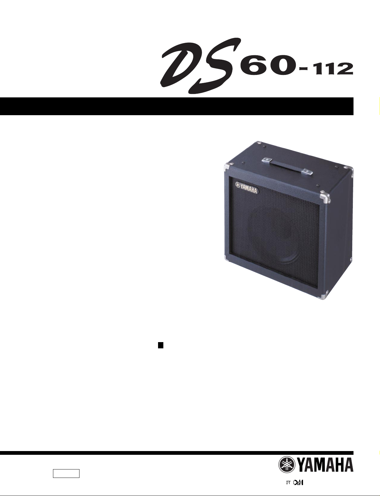
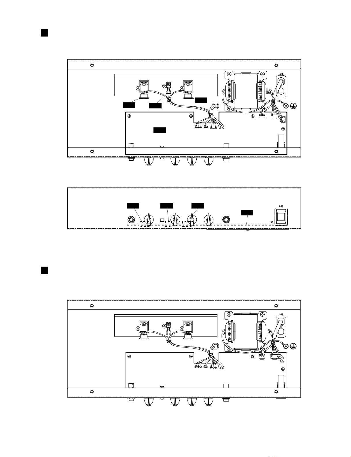
WIRING
W2
W4
W6
W1 W3
W5 BT1
BT2
CN3 CN2
CN1
5
Page 6

DISASSEMBLY PROCEDURE
A. External fittings
1. Handle assembly
1-1. Remove the two (2) screws marked [G60d] and
remove the handle.
2. Corner metal fixture
2-1. Remove the two (2) screws marked [G50] and
remove the corner metal fixture. (Fig. 1)
3. Leg
3-1. Remove the one (1) screw marked [G110] and
remove the leg. (Fig. 1)
[G50]
[G60d]
[G50]: Oval Head Tapping Screw-1 3.5X16 MFN133 (V3833600)
[G60d]: Oval Flat Head Screw 5.0X25 FNM3-2B (V3743700)
[G110]: Truss Head Tapping Screw-1 4.0X20 MFZN2BL (O3747290)
Fig.1
[G110]
4. Amplifier Unit
4-1. Remove the four (4) screws marked [80] and four
(4) angle washers marked [90] from the rear panel.
(Fig. 2)
4-2. Remove the four (4) screws marked [30] and four
(4) angle washers marked [40] from the top panel.
(fig. 2)
5. Speaker
5-1. Remove the four (4) screws marked [80] and four
(4) angle washers marked [90] from the rear panel.
(Fig. 2)
5-2. Remove the four (4) screws marked [70]. The
speaker can then be removed. (Fig. 2)
[30][40]
[70]
[80]
[90]
[30]: Oval Head Screw 5.0X35 MFV2BL (V3749300)
[40]: Washer 5S MFC2BL (EW300020)
[70]: Hexagonal Nut 4.0 MFZN2Y (O3760900)
[80]: Oval Head Tapping Screw-1 4.0X30 MFC2BL (V3749400)
[90]: Washer 4S MFC2BL (VB890200)
Fig.2
6
Page 7

B. Amplifier Unit
6. MAIN circuit board 1/4
6-1. Remove the amplifier unit (See Item 4 above.)
6-2. Remove the four (4) scre ws marked [30], four (4) knobs
of Ro tary variable resisters, four (4) hexagonal nuts
and one (1) each of INPUT and SLAVE OUT he xagonal
nuts. The MAIN circuit board 1/4 can then be removed.
(Fig. 3)
7. MAIN Circuit Boards 2/4, 3/4, 4/4
7-1. Remove the amplifier unit. (See Item 4 above.)
7-2. Remove the one (1) screw marked [210] from each
circuit board, which can then be removed. (Fig. 3)
8. Power T ransformer
8-1. Remove the amplifier unit. (See Item 4 above.)
8-2. Remove the four (4) screws marked [190A]. The
power transformer can then be removed. (Fig. 3)
DS60-112
9. Heat Sink
9-1. Remove the amplifier unit. (See Item 4 above.)
9-2. Remove MAIN circuit boards 2/4, 3/4 and 4/4.
(See Item 7 above)
9-3. Remove the three (3) screws marked [190B]. The
heat sink can then be removed. (Fig. 3)
[190B]
Hexagonal nut
2/4MAIN
INPUT
[190B] [190B] [190A][210] [210][210]
[30] [30]
Fig.3
3/4MAIN
4/4MAIN
[30]
1/4MAIN
Knob
[30]: Bind Head Tapping Screw-B 3.0X8 MFZN2BL (EP600190)
[190]: Bind Head Tapping Screw-C 4.0X8 MFZN2BL (VC688900)
[210]: Bind Head Screw SP3.0X12 MFZN2Y (VB763800)
[190A] [190A]
SLAVE OUT
[30]
Hexagonal nut
IC BLOCK DIAGRAM
RC4558D-V (IG001390)
IC1, IC2
OP AMP
1
Output A
Inverting
Input A
Non-Inverting
Input A
-DC Voltage Supply
2
3
4-V
+V
+-
+-
8
7
6
5
+DC Voltage
Supply
Output B
Inverting
Input B
Non-Inverting
Input B
7
Page 8

CIRCUIT BOARDS
MAIN Circuit Board
MAIN 1/4
MAIN 2/4
Component side
A
EQ
INPUT
VOLUME TREBLE MIDDLE
8
ON/OFF
A'
Page 9

DS60-112
MAIN 3/4
Component side
A
MAIN 4/4
Component side
BASS
A'
MAIN: CNA-V755090
POWER
ON/OFF
SLAVE OUT
Component side
9
Page 10

IDLING ADJUSTMENT
1. T urn the idling adjustment volume (VR5) counterclockwise
fully .
2. Adjust the VR5 so that the DC voltage between the
terminals of the CN4 is 3mV.
10
Page 11

A HGFEDCB
DS60-112
DS60-112 OVERALL CIRCUIT DIAGRAM
1
1/4MAIN
OP AMP
OP AMP
SPEAKER
2/4MAIN
2
OP AMP
OP AMP
3/4MAIN
3
Destination Power Transformer
Black
White
Black
WhiteGreen
Power Cord Cord Bush
Brown
Blue
Green/Yellow
Brown
Blue
Green/Yellow
Power
Transformer
Destination
Mylar Capacitor
Wire Wound Resistor
Flame Proof Carbon Resistor
Metal Oxide Film Resistor
KEC-54236
4/4MAIN
4
5
DS60-112DS60-112
6
HFGEDCBA
Page 12

POWERED SPEAKER
PARTS LIST
CONTENTS
OVERALL ASSEMBLY .............................................. 2
AMPLIFIER UNIT ........................................ 4
ELECTRICAL PARTS ............................................. 6
Notes : DESTINATION ABBREVIATIONS
A : Australian model
B : British model
C : Canadian model
D : German model
E : European model
F : French model
H : North European model
I : Indonesian model
J : Japanese model
M: South African model
O: Chinese model
Q: South-east Asia model
T : Taiwan model
U : U.S.A. model
V : General export model (110V)
W: General export model (220)
N,X : General export model
Y : Export model
WARNING
Components having special characteristics are marked and must be replaced with parts having
specification equal to those originally installed.
The numbers “QTY” show quantities for each unit.
The parts with “--” in “PART NO.” are not available as spare parts.
This mark “ } ” in the REMARKS column means these parts are interchangeable.
The second letter of the shaded (
The second letter of the shaded (
) part number is O, not zero.
) part number is I, not one.
Page 13

DS60-112
OVERALL ASSEMBLY
20
G60b
G70
70
50
10
120
30
40
110
100
G30
G100
G10
G20
G110
G80
G60a
G60
G60b
G60c
G50
G40
G50
G90
80
90
2
Page 14

DS60-112
REF NO. PART NO. DESCRIPTION REMARKS QTY
*
10 Amplifier Unit J (V750430)
*
10 Amplifier Unit H (V750450)
*
10 Amplifier Unit U,C (V750440)
*
10 Amplifier Unit B (V750460)
*
20 Overall Assembly (V750470)
*
G10 Cabinet Assembly (V750480)
*
G20 Vinyl Leather PVC#507 (V369430)
G30 Saran Net #1059 (V369860)
G40 Conner Protector 803
V3694400
G50 Oval Head Tapping Screw-1 3.5X16 MFNI33 16 01
V3833600
G60 Handle Assembly 06
*
*
*
*
V3630300
G60a Handle GA/BA (V362340)
G60b Handle Plate GA/BA (V362350) 2
G60c Handle Angle GA/BA (V363020)
G70 Oval Head Screw 5.0X25 FNM3-2B 201
V3743700
G80 Screw 4.0X40 MFC2BL 4
V3749500
G90 Truss Head Tapping Screw-1 4.0X30 MFZN2Y 601
03747400
G100 Leg 401
VV085600
G110 Truss Head Tapping Screw-1 4.0X20 MFZN2BL 401
03747290
30 Oval Head Screw 5.0X35 MFC2BL 4
V3749300
40 Washer 5S MFC2BL 401
EW300020
50 Speaker SEVENTY 80
X0338A00
70 Hexagonal Nut 4.0 MFZN2Y 401
03760900
80 Oval Head Tapping Screw-1 4.0X30 MFC2BL 8
V3749400
90 Washer 4S MFC2BL 801
VB890200
100 Name Plate GA/BA
V3624100
110 Truss Head Tapping Screw-1 3.0X10 FCM3-BL 2
V3623800
120 Label U,C (VA03930) 03
OVERALL ASSEMBLY DS60-112
Overall Assembly J (V750350)
--
Overall Assembly U,C (V750360)
--
Overall Assembly H (V750370)
--
Overall Assembly B (V750380)
--
--
--
--
--
--
--
--
--
--
--
--
--
RANK
: New Parts
RANK: Japan only
3
Page 15

DS60-112
AMPLIFIER UNIT
190
30
155
140
20
60
80
70
200
190
210
210
200
180
150
160
170
80
130
120
40
50
90
100
110
220
10
30
4
Page 16

DS60-112
REF NO. PART NO. DESCRIPTION REMARKS QTY
*
10 Chassis J
*
*
*
*
*
*
*
V7504900
10 Chassis U,C
V7505000
10 Chassis H
V7505100
20 Circuit Board J,U
V7550900
20 Circuit Board H
V7551000
30 Bind Head Tapping Screw-B 3.0X8 MFZN2BL 501
EP600190
40 Knob (CH)
V3694100
50 Button (S) GRAY EQ ON/OFF 01
VZ429100
60 Power Switch Knob POWER ON/OFF 01
VU859000
70 Escutcheon, Power Switch 02
VU859100
80 Film, Power Switch 13X8X0.15 2
V4126900
90 Hexagonal Nut 9.0 12X2 MFNI33 01
LX200060
100 Flat Washer 9X14 0.5 FNM3 01
VL802300
110 Toothed Lock Washer-A 9.0 MFZN2Y 01
ET800150
120 Hexagonal Nut 12.0 14X2 MFC2BL 01
VD794100
130 Insulation Sheet
V3755700
140 Power Transformer J J
X0239B00
140 Power Transformer UC U,C
X0240B00
140 Power Transformer E E,B
X0241B00
150 Power Cord E H05VV-F3X0.75 6A H 06
VV058200
150 Power Cord BS H05VV-F3X0.75 B 08
VV058300
150 Power Cord UC SJT 3X#18 10A U,C 06
VV205600
150 Power Cord J VCTF 2X0.75 7A J 05
VZ461100
155 Bind Head Screw 4.0X8 MFZN2BL U,C,H,B 01
VP156800
160 Cord Stopper SR-5R1 J,H,B 01
VV103000
160 Cord Stopper SR-6P1 U,C 01
VV103100
170 Cord Stopper SR-4N-4 01
CB072750
180 Heat Sink (V612570)
190 Bind Head Tapping Screw-C 4.0X8 MFZN2BL 701
VC688900
200 Insulation Sheet UNISHEET T=0.15 2
V3637600
210 Bind Head Screw SP 3.0X12 MFZN2Y 3 01
VB763800
220 Cord Holder 301
VV104600
Amplifier Unit J (V750430)
--
Amplifier Unit U,C (V750440)
--
Amplifier Unit H (V750450)
--
Amplifier Unit B (V750460)
--
VOLUME,TREBLE,MIDDLE,BASS
--
402
RANK
: New Parts
RANK: Japan only
5
Page 17

DS60-112
ELECTRICAL PARTS
REF NO. PART NO. DESCRIPTION REMARKS QTY
*
*
*
V7550900
V7551000
VV319600
BT1 Wire Assembly #18 2P L 300
V3632400
C01 Electrolytic Cap. 1.00 50.0V 01
UR866100
C02 Ceramic Capacitor-SL 100P 50V J 01
VZ353500
C03 Ceramic Capacitor-SL 100P 50V J 01
VZ353500
C04 Electrolytic Cap. 1.00 50.0V 01
UR866100
C05 Ceramic Capacitor-B 1000P 50V K 01
VZ353900
C06 Electrolytic Cap. 10.00 25.0V 01
UR847100
C07 Electrolytic Cap. 3.30 50.0V 01
UR866330
C08 Mylar Capacitor 6800P 50V J 01
VV061200
C09 Electrolytic Cap. 0.33 50.0V
UR865330
C10 Mylar Capacitor 2200P 50V J 01
VV060300
C11 Mylar Capacitor 0.068 50V J 01
VV062600
C12 Ceramic Capacitor-SL 100P 50V J 01
VZ353500
C13 Electrolytic Cap. 10.00 25.0V 01
UR847100
C14 Electrolytic Cap. 1.00 50.0V 01
UR866100
C15 Electrolytic Cap. 4.70 50.0V 01
UR866470
C16 Electrolytic Cap. 1.00 50.0V 01
UR866100
C17 Ceramic Capacitor-B 1000P 50V K 01
VZ353900
C18 Electrolytic Cap. 47.00 50.0V 01
UR867470
-20 Electrolytic Cap. 47.00 50.0V 01
UR867470
C21 Ceramic Capacitor-SL 100P 50V J 01
VZ353500
C22 Electrolytic Cap. 100.00 35.0V 01
UR858100
C23 Ceramic Capacitor-B 220P 50V K 01
VZ353600
C24 Ceramic Capacitor-B 220P 50V K 01
VZ353600
C25 Mylar Capacitor 0.1 50V J 01
VV062800
C26 Mylar Capacitor 0.1 50V J 01
VV062800
C27 Electrolytic Cap. 10.00 25.0V 01
UR847100
C28 Electrolytic Cap. 10.00 25.0V 01
UR847100
C29 Capacitor 0.01 400V J.U.C.S 02
VV520600
C30 Polypropylene Capacitor 0.022U/250V
V3632700
C31 Polypropylene Capacitor 0.022U/250V
V3632700
C32 Electrolytic Cap.-LP 3300U 50V SNAP IN
V3632800
C33 Electrolytic Cap.-LP 3300U 50V SNAP IN
V3632800
C34 Electrolytic Cap. 10.00 25.0V 01
UR847100
C35 Electrolytic Cap. 10.00 25.0V 01
UR847100
CN1 Base Post 2P TE 01
VG879900
CN2 Base Post 4P TE 01
LB932040
CN3 Base Post 5P TE 01
LB932050
CN4 Base Post 2P TE 01
VV066200
D01 Diode 1SS82TD 01
IF005560
D02 Diode 1SS133,176,HSS104 01
VD631600
DB1 Diode Stack PBU403 4.0A 200V 03
VV518200
FT1 Fuse 2SK30ATM-Y Y 03
IE000010
FZ1 Fuse TDS 2A 250V J/U/C J,U,C 01
VV070600
FZ1 Fuse TSD 1A 250V SEMKO H,B 01
VV071200
FZ2 Fuse TDS 2A 250V J/U/C J,U,C 01
VV070600
FZ2 Fuse TDS 2A 250V SEMKO H,B 01
VV071500
FZ3 Fuse TDS 2A 250V J/U/C J,U,C 01
VV070600
FZ3 Fuse TDS 2A 250V SEMKO H,B 01
VV071500
IC1 IC RC4558D-V OP AMP 03
IG001390
IC2 IC RC4558D-V OP AMP 03
IG001390
JK1 Phone Jack HTJ-064-12I INPUT 01
V3633400
JK2 Phone Jack HTJ-064-11I SLAVE OUT
V6176400
LD1 LED Red LT311G41BAC 01
V3091800
R01 Carbon Resistor 2.2K 1/4 J 01
HF456220
R02 Carbon Resistor 100.0K 1/4 J 01
HF458100
R03 Carbon Resistor 100.0K 1/4 J 01
HF458100
R04 Carbon Resistor 220.0 1/4 J 01
HF455220
R05 Carbon Resistor 680.0 1/4 J 01
HF455680
R06 Carbon Resistor 3.3K 1/4 J 01
HF456330
R07 Carbon Resistor 100.0K 1/4 J 01
HF458100
R08 Carbon Resistor 680.0 1/4 J 01
HF455680
R09 Carbon Resistor 100.0K 1/4 J 01
HF458100
R10 Carbon Resistor 1.0K 1/4 J 01
HF456100
R11 Carbon Resistor 10.0K 1/4 J 01
HF457100
: New Parts
ELECTRICAL PARTS
Circuit Board MAIN J,U MAIN1/4-4/4(X0097A0)
Circuit Board MAIN H MAIN1/4-4/4(X0097A0)
Jumper Wire 0.60 (VV29140) 17 01
--
Fuse Holder CQ-05CT 601
RANK: Japan only
RANK
6
Page 18

DS60-112
REF NO. PART NO. DESCRIPTION REMARKS QTY
R12 Carbon Resistor 1.0K 1/4 J 01
HF456100
R13 Carbon Resistor 100.0K 1/4 J 01
HF458100
R14 Carbon Resistor 680.0 1/4 J 01
HF455680
R15 Carbon Resistor 220.0 1/4 J 01
HF455220
R16 Carbon Resistor 3.3K 1/4 J 01
HF456330
R17 Carbon Resistor 1.0K 1/4 J 01
HF456100
R18 Carbon Resistor 10.0K 1/4 J 01
HF457100
R19 Carbon Resistor 10.0K 1/4 J 01
HF457100
R20 Carbon Resistor 100.0K 1/4 J 01
HF458100
R21 Carbon Resistor 22.0K 1/4 J 01
HF457220
R22 Carbon Resistor 100.0K 1/4 J 01
HF458100
R23 Carbon Resistor 2.2K 1/4 J 01
HF456220
R24 Carbon Resistor 100.0K 1/4 J 01
HF458100
R25 Carbon Resistor 100.0K 1/4 J 01
HF458100
R26 Carbon Resistor 4.7K 1/4 J 01
HF456470
R27 Carbon Resistor 4.7K 1/4 J 01
HF456470
R28 Carbon Resistor 10.0K 1/4 J 01
HF457100
R29 Carbon Resistor 2.2K 1/4 J 01
HF456220
R30 Carbon Resistor 56.0K 1/4 J 01
HF457560
R31 Carbon Resistor 1.5K 1/4 J 01
HF456150
R32 Carbon Resistor 470.0 1/4 J 01
HF455470
R33 Carbon Resistor 12.0K 1/4 J 01
HF457120
R34 Carbon Resistor 1.0K 1/4 J 01
HF456100
R35 Carbon Resistor 1.0K 1/4 J 01
HF456100
R36 Carbon Resistor 56.0K 1/4 J 01
HF457560
R37 Carbon Resistor 3.3K 1/4 J 01
HF456330
R38 Carbon Resistor 5.6K 1/4 J 01
HF456560
R39 Carbon Resistor 1.0K 1/4 J 01
HF456100
R40 Carbon Resistor 2.2K 1/4 J 01
HF456220
R41 Carbon Resistor 220.0 1/4 J 01
HF455220
R42 Carbon Resistor 3.3K 1/4 J 01
HF456330
R43 Carbon Resistor 220.0 1/4 J 01
HF455220
R44 Flame Proof C. Resistor 100 1/4 J 01
VV276800
R45 Carbon Resistor 330.0 1/4 J 01
HF455330
R46 Carbon Resistor 150.0 1/4 J 01
HF455150
R47 Carbon Resistor 180.0 1/4 J 01
HF455180
R48 Wire Wound Resistor 0.33 5W J
V4480100
R49 Wire Wound Resistor 0.33 5W J
V4480100
R50 Metal Oxide Film Resistor 4.7 1W J 01
V3632900
R51 Wire Wound Resistor 0.33 5W J
V4480100
R52 Metal Oxide Film Resistor 2.2K 3W J
V3633200
R53 Carbon Resistor 1.0K 1/4 J 01
HF456100
-56 Carbon Resistor 1.0K 1/4 J 01
HF456100
R57 Carbon Resistor 5.6K 1/4 J 01
HF456560
SW1 Push Switch SDDLB11874-YL 03
VV059400
SW2 Push Switch SPPJ22SE01 02
V3633600
TR01 T ransistor 2SC1815 Y ,GR 01
IC1815M0
TR02 Transistor 2SA1015 O,Y 01
IA101590
TR03 Transistor 2SC2878 A,B 01
IC287820
TR04 Transistor 2SA970 GR,BL 01
IA097030
TR05 Transistor 2SA970 GR,BL 01
IA097030
TR06 Transistor 2SC2705 O,Y 01
VE198800
TR07 Transistor 2SC3421 O,Y 02
IC342100
TR08 Transistor 2SA1358 O,Y 02
IA135800
TR09 Pair Transistor A1492(Z)/C3856(Z) 05
VV597200
TR10 Transistor 2SC3421 O,Y 02
IC342100
VR1 Rotary Variable Resistor RK09L1120 50KA
*
*
*
*
*
*
V7636900
VR2 Rotary Variable Resistor RK09L1120 10KB TREBLE,MID,BASS
V7636800
-4 Rotary V ariable Resistor RK09L1120 10KB
V7636800
VR5 Trimmer Potentiometer B 1K TB655MC
V3633500
W1W2 Connector Assembly B&B #24 3P L 200 (V363250)
W3W4 Connector Assembly B&B #26 3P L 150 (V620410)
W5W6 Connector Assembly B&B #24 3P L 200 (V363250)
ZD1 Zener Diode MTZ J 15.0B 15.0V 01
-4 Zener Diode MTZ J 15.0B 15.0V 01
--
--
-VG440800
VG440800
VOLUME
RANK
*
*
*
: New Parts
X0338A00
X0239B00
X0240B00
Speaker SEVENTY 80
Power Transformer J J
Power Transformer UC U,C
RANK: Japan only
7
Page 19

DS60-112
REF NO. PART NO. DESCRIPTION REMARKS QTY
*
X0241B00
VZ461100
VV205600
VV058300
VV058200
Power Transformer E E,B
Power Cord J VCTF 2X0.75 7A J 05
Power Cord UC SJT 3X#18 10A U,C 06
Power Cord BS H05VV-F3X0.75 B 08
Power Cord E H05VV-F3X0.75 6A H 06
RANK
8
: New Parts
RANK: Japan only
 Loading...