

Page 1
DS2416
DIGITAL MIXING CARD
Owner’s Manual
Mode d’emploi
Bedienungsanleitung
Manual de instrucciones
取扱説明書
M
Page 2

COMPLIANCE INFORMATION STATEMENT
(DECLARATION OF CONFORMITY PROCEDURE)
Responsible Party: YAMAHA CORPORATION OF AMERICA
Address: 6600 Orangethorpe Avenue, Buena Park, Calif. 90620 U.S.A.
Telephone: 1-714-522-9011
FAX: 1-714-739-2680
Type of Equipment: DIGITAL MIXING CARD
Model Name: DS2416
This device complies with Part 15 of the FCC Rules.
Operation is subject to the following conditions:
1) this device may not cause harmful interference, and
2) this device must accept any interference received including interference that may cause undesired operation.
FCC INFORMATION (U.S.A.)
1. IMPORTANT NOTICE: DO NOT MODIFY THIS UNIT! This product, when installed as indicated in the instructions contained in this manual, meets FCC
requirements. Modifications not expressly approved by Yamaha may void your authority, granted by the FCC, to use the product.
2. IMPORTANT: When connecting this product to accessories and/or another product use only high quality shielded cables. Cable/s supplied with this product MUST
be used. Follow all installation instructions. Failure to follow instructions could void your FCC authorization to use this product in the USA.
3. NOTE: This product has been tested and found to comply with the requirements listed in FCC Regulations, Part 15 for Class “B” digital devices. Compliance with
these requirements provides a reasonable level of assurance that your use of this product in a residential environment will not result in harmful interference with
other electronic devices. This equipment generates/uses radio frequencies and, if not installed and used according to the instructions found in the users manual, may
cause interference harmful to the operation of other electronic devices. Compliance with FCC regulations does not guarantee that interference will not occur in all
installations. If this product is found to be the source of interference, which can be determined by turning the unit “OFF” and “ON”, please try to eliminate the
problem by using one of the following measures: Relocate either this product or the device that is being affected by the interference. Utilize power outlets that are on
different branch (circuit breaker or fuse) circuits or install AC line filter/s. In the case of radio or TV interference, relocate/reorient the antenna. If the antenna lead-in
is 300 ohm ribbon lead, change the lead-in to coaxial type cable. If these corrective measures do not produce satisfactory results, please contact the local retailer
authorized to distribute this type of product. If you can not locate the appropriate retailer, please contact Yamaha Corporation of America, Electronic Service
Division, 6600 Orangethorpe Ave, Buena Park, CA 90620
The above statements apply ONLY to those products distributed by Yamaha Corporation of America or its subsidiaries.
Page 3

1
Contents
Introduction . . . . . . . . . . . . . . . . . . . . . . . . . . . . . . . . . 3
Yamaha DSP Factory . . . . . . . . . . . . . . . . . . . . . . . . . . . . . . 3
Important Note . . . . . . . . . . . . . . . . . . . . . . . . . . . . . . . . . . . 3
System Requirements . . . . . . . . . . . . . . . . . . . . . . . . . . . . . . 4
System Notes . . . . . . . . . . . . . . . . . . . . . . . . . . . . . . . . . . . . . 4
Compatible Software . . . . . . . . . . . . . . . . . . . . . . . . . . . . . . 4
Features . . . . . . . . . . . . . . . . . . . . . . . . . . . . . . . . . . . . . 5
General . . . . . . . . . . . . . . . . . . . . . . . . . . . . . . . . . . . . . . . . . . 5
Mixer . . . . . . . . . . . . . . . . . . . . . . . . . . . . . . . . . . . . . . . . . . . 5
Recorder . . . . . . . . . . . . . . . . . . . . . . . . . . . . . . . . . . . . . . . . . 5
Connections . . . . . . . . . . . . . . . . . . . . . . . . . . . . . . . . . 6
Rear . . . . . . . . . . . . . . . . . . . . . . . . . . . . . . . . . . . . . . . . . . . . 6
Internal . . . . . . . . . . . . . . . . . . . . . . . . . . . . . . . . . . . . . . . . . . 7
Installing the DS2416 . . . . . . . . . . . . . . . . . . . . . . . . . . 8
Testing the DS2416 . . . . . . . . . . . . . . . . . . . . . . . . . . . 9
Installing the Test Program . . . . . . . . . . . . . . . . . . . . . . . . . 9
Using the Test Program . . . . . . . . . . . . . . . . . . . . . . . . . . . . 9
Wordclocks . . . . . . . . . . . . . . . . . . . . . . . . . . . . . . . . . . 10
Recording Digitally to the DS2416 . . . . . . . . . . . . . . . . . . . 11
Recording Digitally to DAT . . . . . . . . . . . . . . . . . . . . . . . . . 11
Digitally Cascading DS2416 Cards . . . . . . . . . . . . . . . . 12
DS2416 Q&A (Questions & Answers) . . . . . . . . . . . . . . 13
Troubleshooting . . . . . . . . . . . . . . . . . . . . . . . . . . . . . . 14
Effects Programs . . . . . . . . . . . . . . . . . . . . . . . . . . . . . . 15
Block Diagram . . . . . . . . . . . . . . . . . . . . . . . . . . . . . . . . 18
Specifications . . . . . . . . . . . . . . . . . . . . . . . . . . . . . . . . 20
Effects Parameters . . . . . . . . . . . . . . . . . . . . . . . . . . . 149
DS2416—Owner’s Manual
Page 4

2
Important Notices
• Do not place the DS2416 in an area subject to excessive heat, direct sunlight, excessive humidity, or dust.
• Keep the DS2416 inside its antistatic bag until you are ready to install it.
• To prevent handling damage, hold the DS2416 by the edges or bracket.
• If you accidentally touch the card edge connections, remove any fingerprints using a dry tissue.
• Do not place objects on top of the DS2416, and do not put it down in a
place where other objects are likely to be placed on top of it.
• Before removing your computer’s cover, turn it off and remove the power
cord.
• To prevent static electricity damage, touch a grounded metal part of your
computer, such as the power supply case, before handling the DS2416.
Packing List
• DS2416 Digital Mixing Card
• Driver and Test program floppy disk
• 14-pin to 16-pin cable
• This manual
Trademarks
IBM PC is a registered trademark of International Business Machines. Korg is
a trademark of Korg, Inc. Pentium is a registered trademark of Intel. Sound
Blaster is a registered trademark of Advanced WavEffects. Windows 95 is a
trademark of Microsoft. Yamaha is a trademark of Yamaha Corporation. All
other trademarks are the property of their respective holders and are hereby
acknowledged.
Copyright
No part of the DS2416 Owner’s Manual may be reproduced or distributed in
any form or by any means without the prior written authorization of Yamaha
Corporation, Inc.
© 1998 Yamaha Corporation. All rights reserved.
Keep this manual for future reference!
DS2416—Owner’s Manual
Page 5

Introduction
Thank you for purchasing the Yamaha DS2416 Digital Mixing Card. With
8-track simultaneous recording, 16-track simultaneous playback, 24-channel
mixing, 4-band parametric EQ, effects, and dynamics, the DS2416 provides a
complete digital recording studio inside a regular personal computer. Unlike
other audio cards, the DS2416’s five DSPs take the load off the computer’s
main processor leaving it free to concentrate on timing and other tasks while
the DS2416 takes care of high-quality effects, EQ, and dynamics processing.
In some cases, the DS2416’s onboard processing powerhouse may allow audio
software to record and playback a greater number of tracks.
For ease of installation and high data throughput, the DS2416 uses the industry-standard PCI (Peripheral Component Interconnect) bus. Sound cards can
be connected digitally, or two DS2416 cards can be digitally cascaded for
48-channel mixing, each providing 2-channel analog inputs and outputs,
with 20-bit 128-times oversampling A/D converters and 20-bit 8-times oversampling D/A converters, and stereo coaxial digital input and output. Inputs
and outputs can be expanded using the optional AX44 Audio Expansion Unit,
which offers four 1/4-inch analog inputs—two of which can be used with
microphones—four 1/4-inch analog outputs and a stereo headphone jack.
Two AX44s can be used with each DS2416 card for eight analog inputs and
outputs.
Introduction
3
Yamaha DSP Factory
The DS2416 Digital Mixing Card forms the heart of the Yamaha DSP Factory
system, a range of products designed to bring professional digital multitrack
recording and mixing to personal computers. Other DSP Factory products
include the AX44 Audio Expansion Unit, and several analog and digital
multi-channel input and output options are currently under development.
Check out the Yamaha Professional Audio Web site for the latest information
<http://www.yamaha.co.jp/product/proaudio/homeenglish/>.
Important Note
Whether you can actually use all the DS2416 functions that appear in the
manual will depend on your audio software.
DS2416—Owner’s Manual
Page 6

4
Introduction
System Requirements
• IBM PC compatible PCI bus Windows 95 computer
• DS2416-compatible audio software
System Notes
The DS2416 can be used in any IBM PC-compatible PCI bus personal computer running Windows 95. The DS2416 requires a single 5 V PCI expansion
bus slot, and cannot be used in 3.3 V PCI slots. It’s compliant with PCI version 2.1, requires one IRQ (interrupt request), but no DMA (Direct Memory
Access). Since it’s a PCI card, IRQ settings are made automatically. PCI bus
speeds greater than 33 MHz are not supported.
Processor type, memory, and hard disk requirements are dependent on the
controlling software, not the DS2416. The supplied device driver requires a
few hundred kilobytes of disk space. Although the DS2416 supports 8-track
simultaneous recording and 16-track simultaneous playback, actual performance will depend on the capabilities of your computer and audio software.
Compatible Software
Any software that supports Windows MME (Multimedia Extensions), including the Windows 95 Media Player accessory, can be used with the DS2416 for
recording and playback. To use the mixing functions, however, requires software that supports the DS2416 mixer. As of April 1998, the following software
companies are developing, or have already released software for the DS2416.
Please visit the following Web sites for more information.
•
C-Mexx
Cakewalk
•
Canam Computers
•
Emagic
•
IQS (Innovative Quality Software)
•
Musicator
•
SEK’D
•
•
Sonic Foundry
Steinberg
•
Audio software that doesn’t support all the features of the DS2416 can still use
a basic feature set. However, input and output patching is fixed, as shown in
the “Fixed Patchbay Diagram” on page 25. The Windows 95 Volume Control
can be used to set the stereo master fader and mute, and the level meters display the recording levels.
<http://www.c-mexx.com/>
<http://www.cakewalk.com/>
<http://www.canam-comp.fr/>
<http://www.emagic.de/>
<http://www.iqsoft.com/>
<http://www.musicator.com/>
<http://www.sekd.com/CConsole/StudCcons.htm>
<http://www.sfoundry.com/>
<http://www.steinberg.de/>
DS2416—Owner’s Manual
Page 7

Features
General
Mixer
Features
• PCI bus card (compliant with version 2.1)
• Support for Windows 95 MME (Multimedia Extensions)
• Plug and Play installation
• 5 onboard DSPs take the load off the computer’s main processor
• 2 analog inputs with 20-bit 128-times oversampling A/D converters
• 2 analog outputs with 20-bit 8-times oversampling D/A converters
• Stereo coaxial digital input and output (20- or 24-bit)
• Optional multi-channel analog and digital input and output options
• 24 input channels, 8 bus outs, 6 aux sends (two feeding the onboard
effects processors), and a stereo output
5
• Input channels 21–24 function as effects returns for the onboard effects
• 4-band parametric EQ on all inputs channels and the stereo output
• Dynamics processors with reduction meters on all inputs channels and
the stereo output
• Two onboard effects processors with Yamaha ProR3/REV500 quality
• Input delay on input channels 1–20
• Signal level metering for all inputs and outputs
• Digital cascading of two DS2416 cards for 48-channel mixing
• 32-bit digital audio processing
Recorder
• 8-track simultaneous recording
• 16-track simultaneous playback
• Up to 32-bit recording and playback (software dependent)
• Sample-accurate synchronization between tracks
• External synchronization via controlling software
DS2416—Owner’s Manual
Page 8
6
Connections
Connections
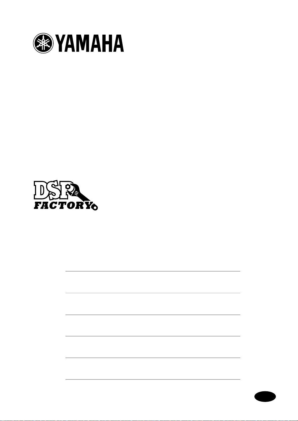
Rear
IN L
1
IN R
OUT L
A
IN L, IN R
Analog IN L and IN R inputs feature phono jacks with a
nominal input level of –10 dBV. Analog to digital conversion
features 20-bit 128-times oversampling techniques. For best
performance use only shielded cables.
OUT L, OUT R
B
Analog OUT L and OUT R outputs feature phono jacks with
a nominal output level of –10 dBV. Digital to analog conversion features 20-bit 8-times oversampling. For best performance use only shielded cables.
2
3
4
OUT R
D IN
D OUT
D IN
C
This two-channel coaxial-type phono connection accepts
digital audio with a 24-bit maximum wordlength. Use connecting cables with a nominal impedance of 75 ohms.
D OUT
D
This two-channel coaxial-type phono connection outputs
digital audio with a 24-bit maximum wordlength. Use connecting cables with a nominal impedance of 75 ohms.
DS2416—Owner’s Manual
Page 9
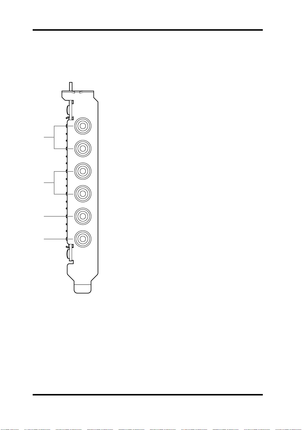
Internal
1 2 3 4
SI
IO
SO
IO-A
Connections
A
B
7
IO-B
A
SI (Serial In) connector
When two DS2416 cards are installed, this connector is connected to the “SO”
connector on the other card using the supplied 14-pin to 16-pin cable. Sound
cards that support the DS2416 can be connected directly to the mixer’s sub
inputs via this connector.
B
SO (Serial Out) connector
When two DS2416 cards are installed, this connector is connected to the “SI”
connector on the other card using the supplied 14-pin to 16-pin cable.
C
IO-A connector
This connector connects to the first optional AX44 Audio Expansion Unit.
D
IO-B connector
This connector connects to the second optional AX44 Audio Expansion Unit.
DS2416—Owner’s Manual
Page 10
8
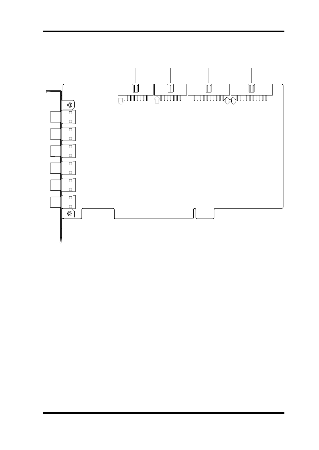
Installing the DS2416
Installing the DS2416
The DS2416 installs into a PCI expansion slot and requires no special jumper
settings or interrupt settings.
See your computer’s manual for full details on installing PCI cards.
1
Turn off the computer and disconnect the power cord.
Remove the computer’s cover.
2
Choose an empty PCI slot for the DS2416, and remove the screw
3
from its expansion-slot cover.
To prevent static electricity from damaging the DS2416, touch a grounded
metal part of your computer, such as the power supply case, before handling
it.
4
Carefully align and insert the DS2416 into the PCI slot.
Secure the DS2416 using the screw removed previously.
5
Important: The DS2416 is grounded via the expansion-card fixing screw, so
be sure to tighten it securely.
Replace the computer’s cover.
6
7
Turn on your computer.
When the New Hardware Found dialog box appears, select “Driver
8
from disk provided by hardware manufacturer”, and then click OK.
9
When the Install From Disk dialog box appears, insert the driver
floppy disk into the floppy disk drive, and then click OK.
10
When the restart dialog box appears, restart your computer.
DS2416—Owner’s Manual
Page 11

Testing the DS2416
A test program is included with the DS2416 to make sure that the card, driver,
and DSPs are functioning correctly.
Installing the Test Program
Insert the supplied floppy disk into the floppy disk drive.
1
2
Double-click Setup.exe and follow the on-screen prompts.
The Test program and its associated files are installed.
Using the Test Program
1
From the Start menu, select Programs, DSP Factory, ds2416ck.exe.
When the Test program window appears, click the CHECK START
2
button to run the tests.
The Test program checks:
1. How many DS2416 cards are installed.
Testing the DS2416
9
2. Whether the DS2416 drivers are installed
3. Whether the DSP chips are functioning correctly.
The test results appear as each test is completed. If all tests are successful, a
sine wave test tone can be produced through the OUT L, OUT R, D OUT, and
outputs 1 through 4 of any connected AX44s by clicking the test tone button.
If a test fails, follow the advice provided.
If the driver test fails again after restarting, try reinstalling the driver.
If the DSP test produces a “DSP ERROR” or “DSP NG” message, the DS2416
has a hardware problem and you should contact your Yamaha dealer.
Click the EXIT button to quit the Test program.
3
DS2416—Owner’s Manual
Page 12

10
Wordclocks
Wordclocks
Unlike analog audio equipment, digital audio equipment must be synchronized when digital audio is transferred from one device to another, otherwise,
the digital audio might not be read correctly and audible noise, glitches, or
clicks may occur. Synchronization is achieved using what’s called a wordclock,
which is a clock signal for synchronizing all the digital audio words in an
audio system. Note that wordclocks are not the same as SMPTE or MIDI
timecode, which are used to synchronize audio recorders, MIDI sequencers,
and so on. Wordclock synchronization refers to the synchronization of the
digital audio processing circuits inside each digital audio device.
In a typical digital audio system, one device acts as the wordclock master and
the other devices act as wordclock slaves, synchronizing to the wordclock
master. If the DS2416 is the only digital audio device in your system, no special wordclock settings are required, as the DS2416 synchronizes to its own
internal wordclock. Add a DAT recorder or digital multitrack recorder, however, and you must decide which device to use as wordclock master and which
devices to use as slaves. Even when you’ve done this and configured your system, it may sometimes be necessary to change the wordclock settings, such as
when recording from a DAT or CD player.
Wordclocks run at the same frequency as the sampling rate. The DS2416 generates its own wordclock at 44.1 kHz (the industry-standard sampling rate for
music CDs) or 48 kHz and can be used as wordclock master. Alternatively, it
can be used as a wordclock slave synchronized to an external wordclock of
between 30.08 kHz and 50.88 kHz (32 kHz –6% to 48 kHz +6%). Converting
the sampling rate of digital audio is a complicated process, so it’s best to use
the 44.1 kHz sampling rate, especially if your work is destined for CD distribution.
Wordclock signals can be distributed via dedicated cables or derived from
standard digital audio connections, such as the D IN and D OUT connections
on the DS2416. With Coaxial digital audio connections, a wordclock signal is
transmitted even when no audio signal is present. The DS2416 can also transmit and receive wordclock signals via its SI, SO, IO-A, and IO-B connectors.
In a system where all devices share a common wordclock, it’s important that
all devices be turned on even when they’re not being used. Turn on the wordclock master first, and then the slaves. When shutting down the system, turn
off the slaves first, and then the master. Before commencing with a recording
session, make sure that all wordclock slaves are synchronized to the master.
Some devices have front panel indicators to show when they are wordclock
synchronized. Refer to the instructions for each device.
DS2416—Owner’s Manual
Page 13
Wordclocks 11
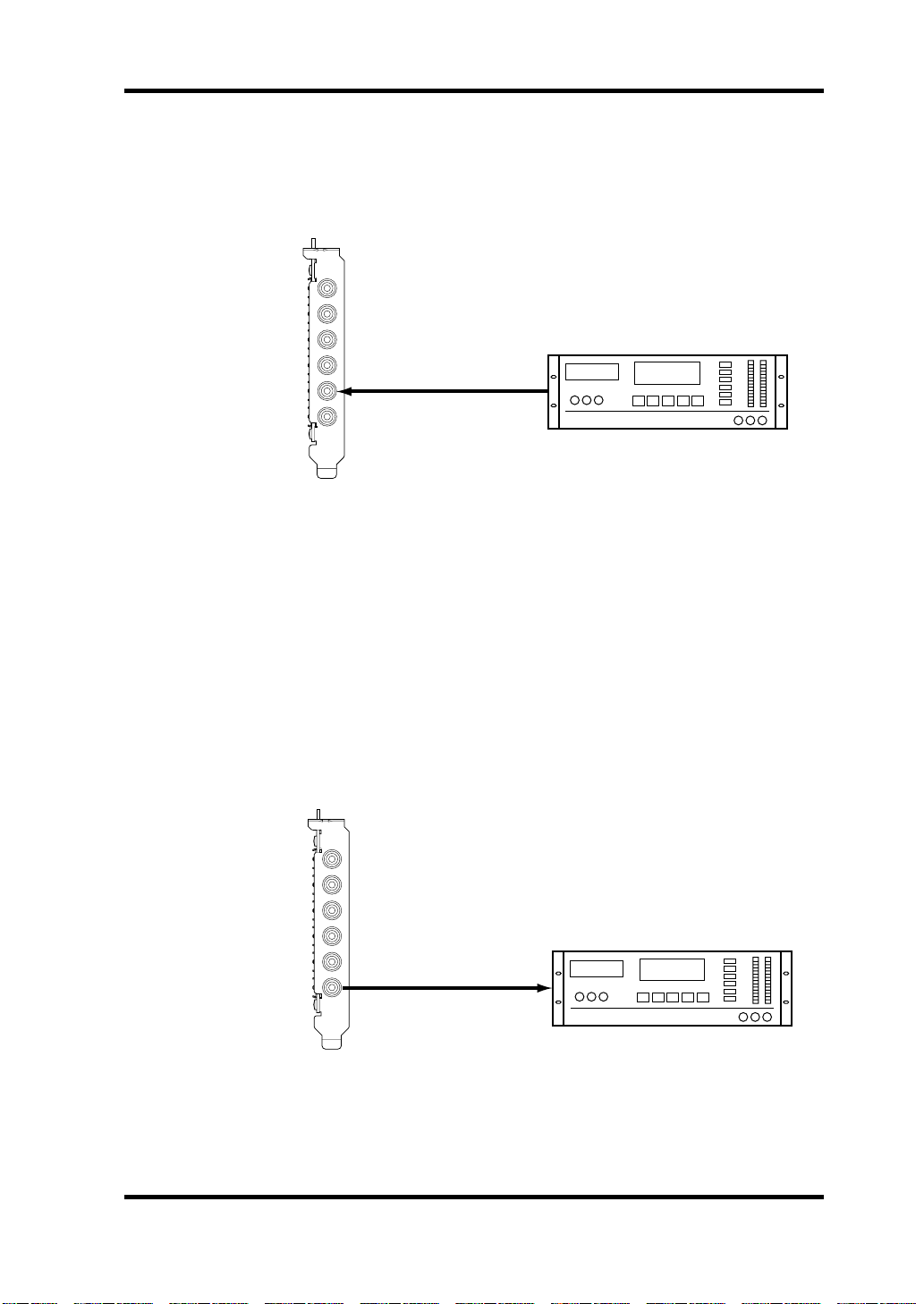
Recording Digitally to the DS2416
In this example, a DAT deck is connected to the DS2416 D IN connector for
digital recording. The DS2416 works as wordclock slave, deriving its wordclock from the D IN connection, and the DAT works as wordclock master.
IN L
IN R
OUT L
OUT R
D IN
D OUT
DS2416
(wordclock slave
Source = D IN)
Digital Out
DAT recorder
(wordclock master)
00.00.00.00
DAT
Recording Digitally to DAT
In this example, the D OUT connector on the DS2416 is connected to the digital input of a DAT recorder for digital mixdown recording. The DS2416
works as wordclock master and the DAT works as wordclock slave. When the
digital input on the DAT recorder is selected as the recording source, the DAT
should automatically synchronize to the wordclock signal coming from the
DS2416. On some DAT recorders, the wordclock source may have to be set
separately. Refer to the instructions supplied with your DAT recorder.
IN L
IN R
OUT L
OUT R
D IN
D OUT
Digital In
DS2416
(wordclock master)
DAT recorder
(wordclock slave)
00.00.00.00
DAT
DS2416—Owner’s Manual
Page 14
12 Digitally Cascading DS2416 Cards
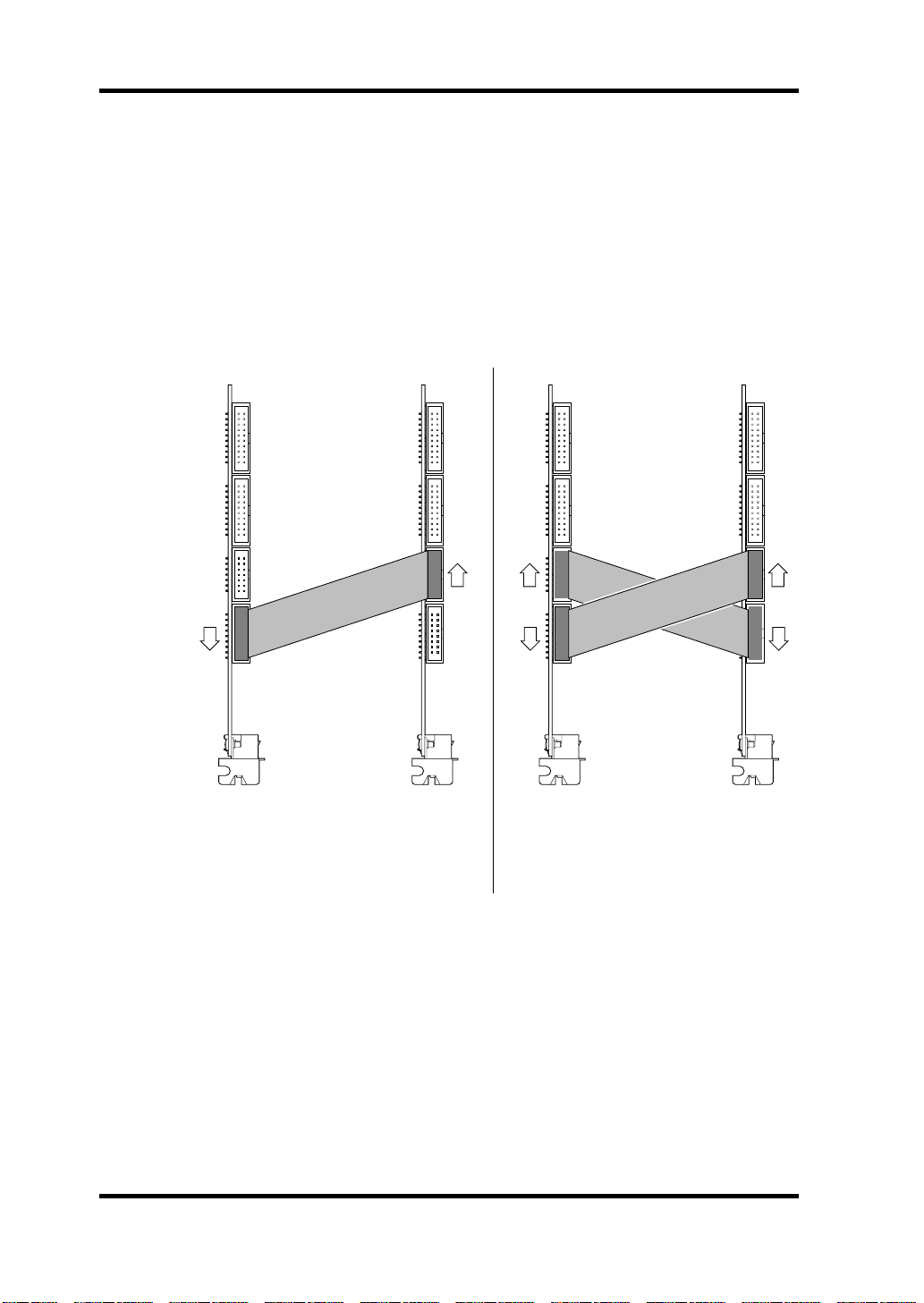
Digitally Cascading DS2416 Cards
Using the digital “SI” and “SO” connectors, two DS2416 cards can be digitally
cascaded for common busing and 48-channel mixing.
1 Install the second DS2416 into a PCI slot adjacent to the first
DS2416, as explained previously.
2 Using the supplied 14-pin to 16-pin cables, connect the “SI” and
“SO” connectors as shown below.
O
I
DS2416 (A) DS2416 (B)
In this example, the buses of DS2416
(A) and (B) are linked together for 48channel mixing. Individual buses from
DS2416 (B) can alternatively be fed to
the sub inputs of DS2416 (A).
3 Replace the computer’s cover.
O
I
DS2416 (A) DS2416 (B)
In this example, the buses of DS2416
(A) and (B) are linked together for 48channel mixing. Individual buses from
either DS2416 can be fed to the other
DS2416.
O
I
DS2416—Owner’s Manual
Page 15

DS2416 Q&A (Questions & Answers) 13
DS2416 Q&A (Questions & Answers)
Q What’s a DSP?
A A DSP, or Digital Signal Processor is a processor optimized for
real-time digital data processing. The DS2416 features the same
DSP as the Yamaha 02R and 03D digital mixing consoles and
ProR3 and REV500 effects processors.
Q At what wordlength is digital audio processed?
A The EQ features a 44-bit data path, 32-bit coefficient, and 54-bit
accumulator. All other mixer sections feature a 32-bit data path,
24-bit coefficient, and 42-bit accumulator.
Q Does the DS2416 have any onboard memory?
A Yes, 3 megabytes, which is used for input, and effects delays.
Q What is the available recording time?
A This depends on the software, selected wordlength, and hard disk
space. In general, two channels of 16-bit digital audio use 10.6
MB/min.
Q How do I synchronize the DS2416 to MIDI Clock, MTC, or SMPTE
timecode?
A If the software and timecode interface support external timecode,
so does the DS2416.
Q Can DS2416 mixer functions be controlled via MIDI?
A If the controlling software supports this, yes.
Q How good are the onboard effects processors?
A As good as those used in the Yamaha ProR3 and REV500 effects
processors.
Q Can the DS2416 be used simultaneously with a Sound Blaster or
Korg 1212 I/O card?
A Yes.
DS2416—Owner’s Manual
Page 16
14 Troubleshooting
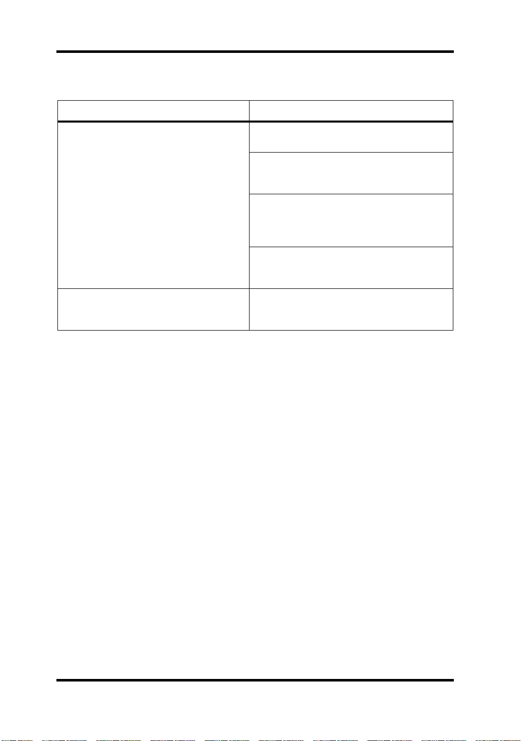
Troubleshooting
Trouble Advice
Make sure that the DS2416 is inserted in the
PCI bus slot correctly.
Make sure that the DS2416 input and outputs
are correctly assigned using the controlling
software.
The DS2416 does not work?
A low-level hum can be heard?
In older computers, some PCI slots may not
function as the bus master, and the DS2416 will
not work in such slots. See your computer’s
manual for more details.
Some PCI cards may conflict with the DS2416.
Try removing cards, or swapping slots with the
DS2416.
The DS2416 is grounded via the expansion-card fixing screw, so be sure to tighten it
securely.
DS2416—Owner’s Manual
Page 17
Effects Programs
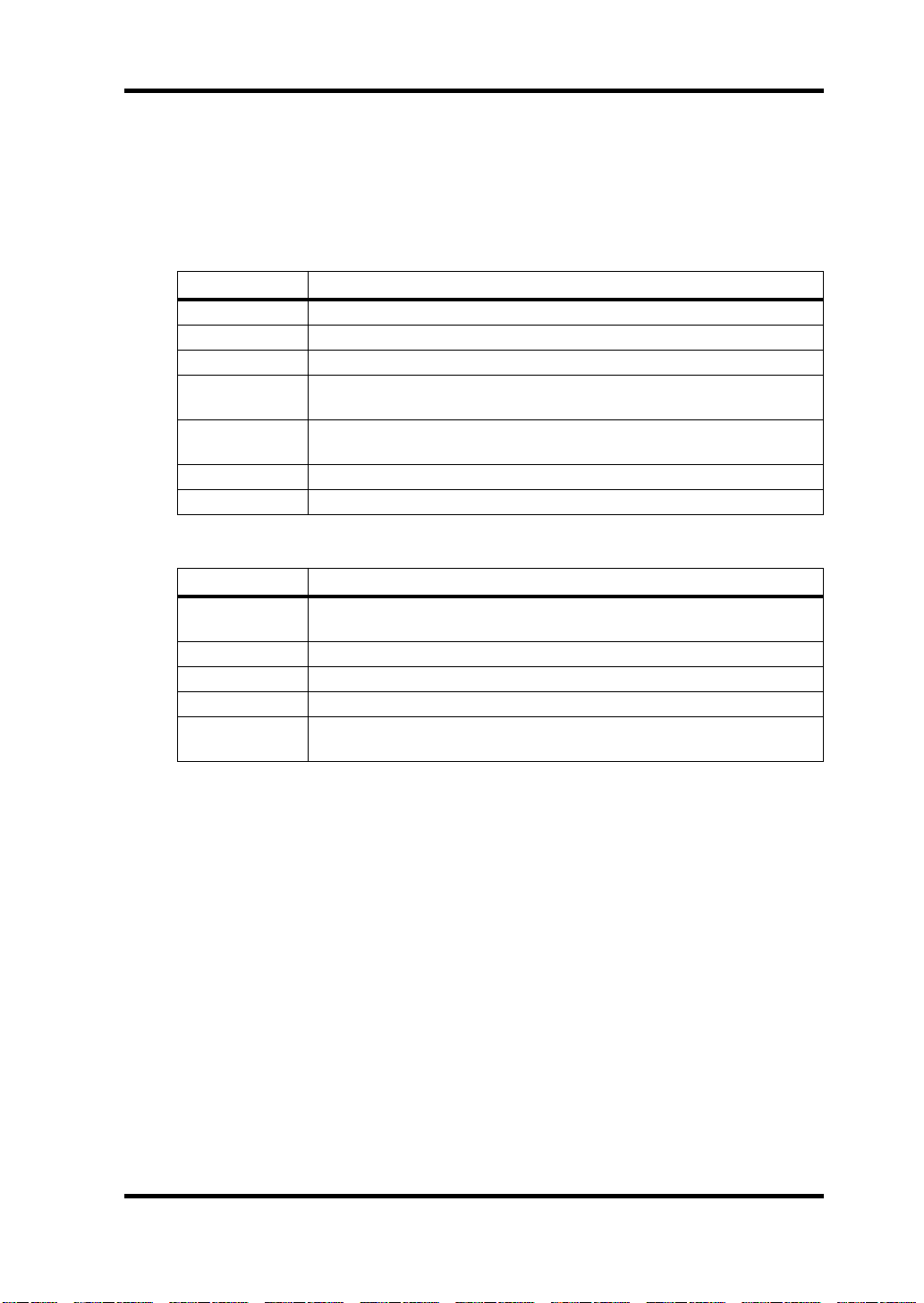
The DS2416 provides the following effects programs. Detailed effects parameters are shown on page 149.
Reverb-type Effects
Type Description
REVERB HALL Reverb simulating a large space such as a concert hall.
REVERB ROOM Reverb simulating the acoustics of a smaller space than REVERB HALL.
REVERB STAGE Reverb designed with vocals in mind.
REVERB PLATE
EARLY REF.
GATE REVERB A type of ER designed for use as gated reverb.
REVERSE GATE A reverse-playback type ER.
Delays
Type Description
MONO DELAY
STEREO DELAY Stereo delay with independent left and right.
MOD.DELAY Mono delay with modulation.
DELAY LCR Three-tap delay (L, C, R).
ECHO
Simulation of a metal-plate reverb unit, producing a feeling of
hard-edged reverberation.
An effect which isolates only the early reflection (ER) component from
reverberation. A flashier effect than reverb is produced.
Mono delay with simple operation. Use when you don't need to use
complex parameter settings.
Stereo delay with additional parameters for more detailed control. The
signal can be fed back from left to right, and right to left.
Effects Programs 15
DS2416—Owner’s Manual
Page 18
16 Effects Programs
Modulation-type Effects
Type Description
CHORUS Three-phase stereo chorus.
FLANGE The well-known flanging effect.
SYMPHONIC
PHASER Stereo phaser with 2–16 stages of phase shift.
AUTO PAN An effect which cyclically moves the sound between left and right.
TREMOLO Tremolo
HQ.PITCH
(Effect 2 only)
DUAL PITCH Stereo pitch shift with left and right pitches set independently.
ROTARY Simulation of a rotary speaker.
RING MOD.
MOD.FILTER An effect which uses an LFO to modulate the frequency of the filter.
Guitar Effects
Type Description
DISTORTION Distortion
AMP SIMULATE Guitar Amp Simulator
A Yamaha proprietary effect that produces a richer and more complex
modulation than chorus.
Only one note is pitch-shifted, but a stable effect is produced.
An effect that modifies the pitch by applying amplitude modulation to
the frequency of the input.
Dynamic Effects
Type Description
DYNA.FILTER Dynamically controlled filter.
DYNA.FLANGE Dynamically controlled flange.
DYNA.PHASER Dynamically controlled phase shifter.
DS2416—Owner’s Manual
Page 19
Combined Effects
Type Description
REV+CHORUS Reverb and chorus in parallel
REV->CHORUS Reverb and chorus in series
REV+FLANGE Reverb and flange in parallel
REV->FLANGE Reverb and flange in series
REV+SYMPHO. Reverb and symphonic in parallel
REV->SYMPHO. Reverb and symphonic in series
REV->PAN Reverb and auto-pan in parallel
DELAY+ER. Delay and early reflections in parallel
DELAY->ER. Delay and early reflections in series
DELAY+REV Delay and reverb in parallel
DELAY->REV Delay and reverb in series
DIST->DELAY Distortion and delay in series
Effects Programs 17
DS2416—Owner’s Manual
Page 20
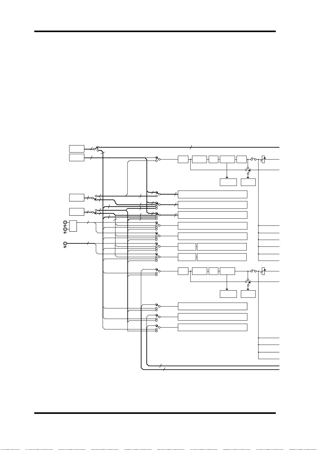
18 Block Diagram
Block Diagram
SERIAL IN
PCI
PLAYBACK(16ch)
IO-B IN(4 or 8ch)
IO-A IN(4 or 8ch)
A IN L
A IN R
D IN
7
4
4
CASCADE IN(16ch)
CH1
CH2-8
CH9-12
CH13-16
CH17
CH18
CH19
CH20
CH21
CH22
CH23
CH24
16 or 8
SI
PCI
4 or 8
IO-B
4 or 8
IO-A
A/D
SUB IN(8ch)
8
16
78
4
8
4
4
2
2
4 4
4
4
4
4
7
4
4
DC-CUT
DE-EMPHASIS
DE-EMPHASIS
DC-CUT
16
ATT/PHASE
ATT/PHASE
4BAND
PEQ
SAME AS CH1
SAME AS CH1
SAME AS CH1
SAME AS CH1
SAME AS CH1
SAME AS CH1
SAME AS CH1
4BAND
PEQ
SAME AS CH21
SAME AS CH21
SAME AS CH21
DYNAMICS
REDUCTION
METER
DYNAMICS
REDUCTION
METER
DELAY
Signal
Signal
CHANNEL
METER
CHANNEL
METER
ON
Pre
Post
ON
Pre
Post
DS2416—Owner’s Manual
2
2
Page 21
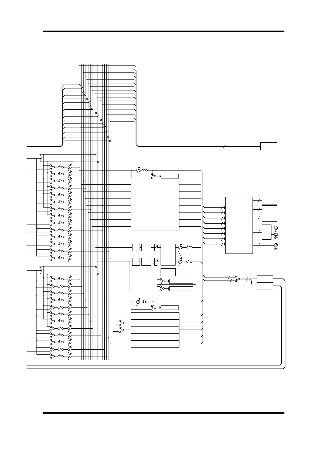
BUS1
STEREO
MASTER
BALANCE
BUS2
BUS3
BUS4
BUS5
BUS6
BUS7
BUS8
STEREO L
STEREO R
AUX1
AUX2
AUX3
AUX4
AUX5
AUX6
BUS AUXSTEREO
12345678 123456LR
BUS1
BUS2
BUS3
BUS4
BUS5
BUS6
BUS7
BUS8
STEREO L
STEREO R
AUX1
AUX2
AUX3
AUX4
AUX5
AUX6
CASCADE OUT(16ch)
Block Diagram 19
16
SO
SERIAL OUT
PAN
Pre/Post
PAN
Pre/Post
ON/OFF
ON/OFF
BUS1
BUS2
BUS3
BUS4
BUS5
BUS6
BUS7
BUS8
AUX1
AUX2
AUX3
AUX4
AUX5
AUX6
BUS1
BUS2
BUS3
BUS4
BUS5
BUS6
BUS7
BUS8
AUX1
AUX2
AUX3
AUX4
STEREO
L
STEREO
R
BUS1
BUS2
BUS3
BUS4
BUS5
BUS6
BUS7
BUS8
AUX1
AUX2
AUX3
AUX4
AUX5
AUX6
BUS
MASTER
ATT
ATT
AUX
MASTER
ON
SAME AS BUS1
SAME AS BUS1
SAME AS BUS1
SAME AS BUS1
SAME AS BUS1
SAME AS BUS1
SAME AS BUS1
4BAND
PEQ
PEQ
STEREO
STEREO
MASTER
MASTER
4BAND
PEQ
ON
SAME AS AUX1
SAME AS AUX1
SAME AS AUX1
SAME AS AUX1
SAME AS AUX1
BUS METER
DYNAMICS
REDUCTION
METER
AUX METER
BALANCE
BALANCE
STEREO L METER
STEREO R METER
BUS 1/2
BUS 3/4
BUS 5/6
BUS 7/8
STEREO L/R
AUX 1/2
AUX 3/4
AUX 5/6
AUX 3/4
AUX 5/6
8
PCI
2
2
2
2
11(15) ST out
2
PATCH BAY
2
2
2
2
2
8 ST in
4 or 8
4 or 8
2
2
BUILT-IN
2
EFFECT 1
BUILT-IN
EFFECT 2
PCI REC OUT(8ch)
IO-A OUT(4 or 8ch)
IO-A
IO-B
IO-B OUT(4 or 8ch)
A OUT L
D/A
A OUT R
D OUT
DS2416—Owner’s Manual
Page 22
20 Specifications
Specifications
General
Sampling rate
Signal delay
(fs = 48 kHz)
Total harmonic distortion
(fs = 48 kHz, +6 dBV, analog input to output)
Frequency response
(fs = 48 kHz, +6 dBV, analog input to output)
Dynamic range
(fs = 48 kHz)
Residual output noise
(D/A input = digital 0)
Input
Output
Effects
(HQ. Pitch type for
Effect 2 only)
Power supply
Maximum power consumption 9.3 W
Temperature
Dimensions (H x L x D)
Weight 170 g (6 oz)
Supplied accessories
1. 44.1 kHz ±6%, 48 kHz ±6%
2. 32 KHz –6% to 48 kHz +6%
3. Bandwidth filter ±0.1 dB (20 Hz to 20 kHz), –60 dB (more than 24.1 kHz)
4. Bandwidth filter as above plus Weighting Filter (IEC60651 A curve, Tolerance:
4
Type 0)
Internal 44.1 kHz, 48 kHz
Internal vari-pitch
External
A/D 620 µs typical
D/A 310 µs typical
3
D/A Typically 94 dB
A/D + D/A Typically 93 dB
4
IN L, IN R 20-bit 128-times oversampling A/D
D IN Consumer format (Coaxial)
OUT L, OUT R 20-bit 8-times oversampling D/A
D OUT Consumer format (Coaxial)
Effect 1 39 types
Effect 2 40 types
Operating +10 to +40˚C
Storage –20 to +55˚C
41.45 to 50.88 kHz
30.08 to 50.88 kHz
Less than 0.02% (20 Hz to 20 kHz)
20 Hz to 20 kHz, –3, +1 dB
Typically –88 dBV
+5 V (1.5 A max)
+12 V (150 mA max)
125.92 x 187.95 x 21.59 mm
(4.95 x 7.4 x 0.85 inch)
PCI Raw Variable Height Short Card
(5 V, 32-bit)
Driver floppy disk
14-pin to 16-pin 100 mm cable x1
1
2
DS2416—Owner’s Manual
Page 23
Specifications 21
Input Channels
De-emphasis (CH19, CH20) Automatically applied as needed
DC Cut Automatically applied as needed
ATT –96 to +12 dB (109 steps)
Phase Normal/reverse
4-band EQ
(12 EQ types per band)
Dynamics
(6 types)
Delay (CH1 to CH20)
On/Off
Fader –Infinity, –90 to +10 dB (128 steps)
Pan 33 steps
Channel meter
Bus send
Aux send
Frequency 20 Hz to 20 kHz (120 steps, 12 points/octave)
Gain –18 to +18 dB (73 steps, 0.5 dB/step)
Q 0.1 to 10.0 (41 steps)
Threshold –54 to 0 dB (55 steps, 1.0 dB/step)
Attack 0 to 120 ms (121 steps, 1 ms/step)
Gain 0 to 18 dB (37 steps, 0.5 dB/step)
Release
Ratio 1.0 to infinity (16 steps)
Knee Hard, 1, 2, 3, 4, 5 (6 steps)
Range –70 to 0 dB (71 steps, 1.0 dB/step)
Hold
Decay
Width 1 to 90 (90 steps, 1.0 dB/step)
Mgain –18 to 0 dB (37 step, 0.5 dB/step)
Reduction
meter
Level –Infinity, –120 to 0 dB (128 steps)
Pre/Post (Pre pan/post pan)
On/Off
Level –Infinity, –120 to 0 dB (128 steps)
Pre/Post (Pre fader/post fader)
On/Off
5 ms to 42.3 s, fs = 48.0 kHz (160 steps)
6 ms to 46.0 s, fs = 44.1 kHz (160 steps)
0.02 ms to 1.96 s, fs = 48.0 kHz (216 steps)
0.02 ms to 2.13 s, fs = 44.1 kHz (216 steps)
5 ms to 42.3 s, fs = 48.0 kHz (160 steps)
6 ms to 46.0 s, fs = 44.1 kHz (160 steps)
–18 to 0 dB (12 steps)
0 to 2,600 samples (2,601 steps)
On/Off
–72 to 0 dB (32 steps)
Pre/Post/Signal
Peak Hold
Decay Fast/Slow
DS2416—Owner’s Manual
Page 24
22 Specifications
Bus Outs 1–8
Bus master fader –Infinity, –120 to 0 dB (128 steps)
On/Off
Bus meter
Aux Sends 1–6
Aux master fader –Infinity, –120 to 0 dB (128 steps)
On/Off
Aux meter
Stereo Output
ATT –96 to +12 dB (109 steps)
4-band EQ
(12 EQ types per band)
Stereo master fader –Infinity, –120 to 0 dB (128 steps)
Dynamics
(6 types)
Balance 33 steps
–72 to 0 dB (32 steps)
Pre/Post fader
Peak Hold
Decay Fast/Slow
–72 to 0 dB (32 steps)
Pre/Post fader
Peak Hold
Decay Fast/Slow
Frequency 20 Hz to 20 kHz (120 steps, 12 points/octave)
Gain –18 to +18 dB (73 steps, 0.5 dB/step)
Q 0.1 to 10.0 (41 steps)
Threshold –54 to 0 dB (55 steps, 1.0 dB/step)
Attack 0 to 120 ms (121 steps, 1 ms/step)
Gain 0 to 18 dB (37 steps, 0.5 dB/step)
Release
Ratio 1.0 to infinity (16 steps)
Knee Hard, 1, 2, 3, 4, 5 (6 steps)
Range –70 to 0 dB (71 steps, 1.0 dB/step)
Hold
Decay
Width 1 to 90 (90 steps, 1.0 dB/step)
Mgain –18 to 0 dB (37 steps, 0.5 dB/step)
Reduction
meter
5 ms to 42.3 s, fs = 48.0 kHz (160 steps)
6 ms to 46.0 s, fs = 44.1 kHz (160 steps)
0.02 ms to 1.96 s, fs = 48.0 kHz (216 steps)
0.02 ms to 2.13 s, fs = 44.1 kHz (216 steps)
5 ms to 42.3 s, fs = 48.0 kHz (160 steps)
6 ms to 46.0 s, fs = 44.1 kHz (160 steps)
–18 to 0 dB (12 steps)
DS2416—Owner’s Manual
Page 25
–72 to 0 dB (32 steps)
Stereo meter
Pre/Post fader
Peak Hold
Decay Fast/Slow
Input Patchbay
Input Selectable Source
CH1 PCI PB1, IO-B2-1
CH2 PCI PB2, IO-B2-2
CH3 PCI PB3, IO-B2-3
CH4 PCI PB4, IO-B2-4
CH5 PCI PB5, IO-B2-5
CH6 PCI PB6, IO-B2-6
CH7 PCI PB7, IO-B2-7
CH8 PCI PB8, IO-B2-8
CH9 PCI PB9, IO-B1-1, SUB IN1, IO-A2-1
CH10 PCI PB10, IO-B1-2, SUB IN2, IO-A2-2
CH11 PCI PB11, IO-B1-3, SUB IN3, IO-A2-3
CH12 PCI PB12, IO-B1-4, SUB IN4, IO-A2-4
CH13 PCI PB13, IO-A1-1, SUB IN5, IO-A2-5
CH14 PCI PB14, IO-A1-2, SUB IN6, IO-A2-6
CH15 PCI PB15, IO-A1-3, SUB IN7, IO-A2-7
CH16 PCI PB16, IO-A1-4, SUB IN8, IO-A2-8
CH17 IN L, IO-A1-1, SUB IN1, IO-A2-1
CH18 IN R, IO-A1-2, SUB IN2, IO-A2-2
CH19 DIN L, IO-A1-3, SUB IN3, IO-A2-3
CH20 DIN R, IO-A1-4, SUB IN4, IO-A2-4
CH21 Effect1 Return L, SUB IN5, IO-A2-5
CH22 Effect1 Return R, SUB IN6, IO-A2-6
CH23 Effect2 Return L, SUB IN7, IO-A2-7
CH24 Effect2 Return R, SUB IN8, IO-A2-8
Specifications 23
PCI PB: wave data, etc., playback
IO-A1: 4-input/4-output device connected to IO-A
IO-A2: 8-input/8-output device connected to IO-A
IO-B1: 4-input/4-output device connected to IO-B
IO-B2: 8-input/8-output device connected to IO-B
DS2416—Owner’s Manual
Page 26
24 Specifications
Output Patchbay
Sources 1 through 8 can be patched to any destination.
Source Destination
1: BUS 1, 2 1: REC 1, 2
2: BUS 3, 4 2: REC 3, 4
3: BUS 5, 6 3: REC 5, 6
4: BUS 7, 8 4: REC 7, 8
5: AUX 1, 2 5: IO-A1-1, 2 (IO-A2-1, 2)
6: AUX 3, 4 6: IO-A1-3, 4 (IO-A2-3, 4)
7: AUX 5, 6 7: IO-B1-1, 2 (IO-B2-1, 2)
8: STL, STR 8: IO-B1-3, 4 (IO-B2-3, 4)
IO-A1: 4-input/4-output device connected to IO-A
IO-A2: 8-input/8-output device connected to IO-A
IO-B1: 4-input/4-output device connected to IO-B
IO-B2: 8-input/8-output device connected to IO-B
9: AOUTL, AOUTR
10: DOUTL, DOUTR
11: IO-A2-5, 6
12: IO-A2-7, 8
13: IO-B2-5, 6
14: IO-B2-7, 8
DS2416—Owner’s Manual
Page 27
Specifications 25
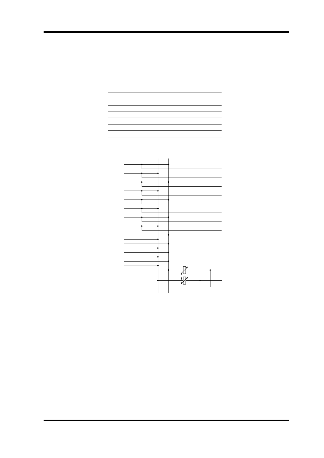
Fixed Patchbay Diagram
When audio software that doesn’t support the DS2416’s mixer is used, input
and output assignments are fixed, as shown below.
Input
IO-A IN 1
IO-A IN 2
IO-A IN 3
IO-A IN 4
D IN L
D IN R
Output
PCI PLAYBACK 1
PCI PLAYBACK 2
PCI PLAYBACK 3
PCI PLAYBACK 4
PCI PLAYBACK 5
PCI PLAYBACK 6
PCI PLAYBACK 7
PCI PLAYBACK 8
PCI PLAYBACK 9
PCI PLAYBACK 10
PCI PLAYBACK 11
PCI PLAYBACK 12
PCI PLAYBACK 13
PCI PLAYBACK 14
PCI PLAYBACK 15
PCI PLAYBACK 16
IN L
IN R
STEREO
MASTER
PCI REC OUT 1
PCI REC OUT 2
PCI REC OUT 3
PCI REC OUT 4
PCI REC OUT 5
PCI REC OUT 6
PCI REC OUT 7
PCI REC OUT 8
IO-A OUT 1
IO-A OUT 2
IO-A OUT 3
IO-A OUT 4
IO-B OUT 1
IO-B OUT 2
IO-B OUT 3
IO-B OUT 4
OUT L
OUT R
D OUT L
D OUT R
DS2416—Owner’s Manual
Page 28
26 Specifications
Analog Inputs
Input level
Nominal
–10 dBV
(316 mV)
Max. before
2
+6 dBV
(1.995 V)
Connector
clip
Phono jack
(unbalanced)
Connection
IN L, IN R
1
1. Inputs feature linear 20-bit 128-times oversampling A/D converters.
2. Where dBV represents a specific voltage, 0 dBV is referenced to 1 V rms.
Actual
load
impedance
10k Ω 600 Ω lines
For use with
nominal
Analog Outputs
Output level
Nominal
–10 dBV
(316 mV)
Max. before
2
+6 dBV
(1.995 V)
Connector
clip
Phono jack
(unbalanced)
Connection
OUT L, OUT R
Actual
source
impedance
1
600 Ω 10k Ω lines
1. Outputs feature linear 20-bit 8-times oversampling D/A converters.
2. Where dBV represents a specific voltage, 0 dBV is referenced to 1 V rms.
For use with
nominal
Digital I/O
Connection I/O Format Level Connector
D IN
D OUT
IO-A, IO-B
SERIAL IN
SERIAL OUT
I
IEC60958 Consumer 0.5 Vpp, 75 Ω
O
IEC60958 Consumer 0.5 Vpp, 75 Ω
4CH or 8CH digital audio inputs
4CH or 8CH digital audio outputs
I/O
32-bit max/channel
Format depends on counterpart
8CH or 16CH digital audio inputs
I
32-bit max/channel
Format depends on counterpart
8CH or 16CH digital audio outputs
O
32-bit max/channel
Format depends on counterpart
5 V CMOS 20-pin connector
5 V CMOS 16-pin connector
5 V CMOS 14-pin connector
Phono jack
(unbalanced)
Phono jack
(unbalanced)
DS2416—Owner’s Manual
Page 29
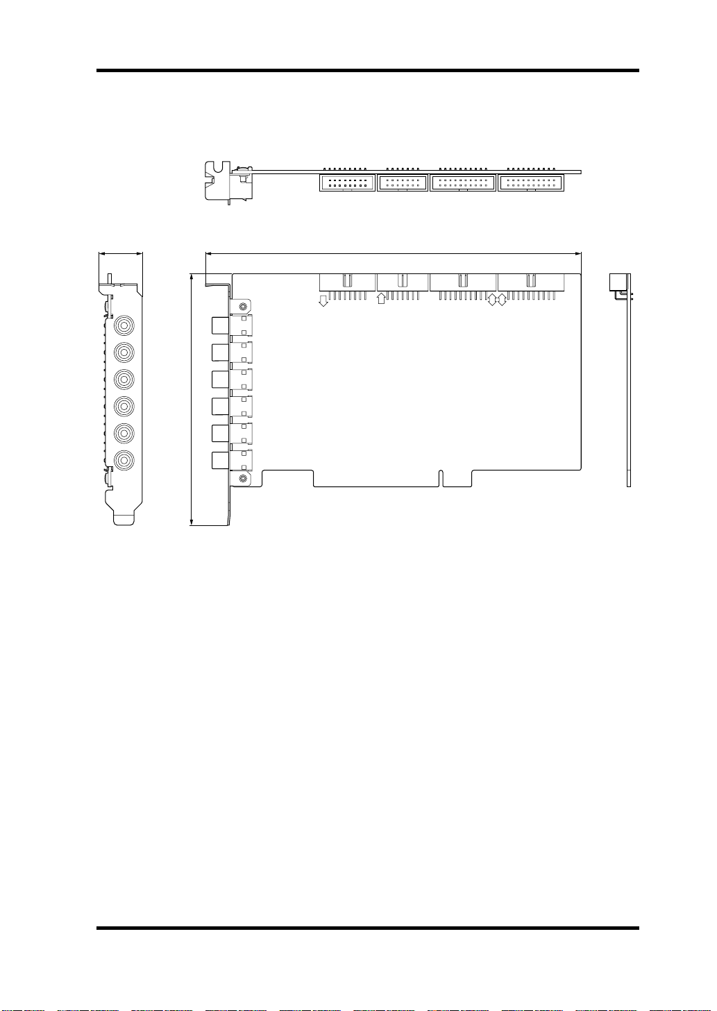
Dimensions
Specifications 27
21.59
OUT L
OUT R
D OUT
IN L
IN R
D IN
187.95
IO-B
125.92
SI
IO
SO
IO-A
A
B
Unit: mm
Specifications and external appearance are subject to change without notice.
DS2416—Owner’s Manual
Page 30
DS2416
DIGITAL MIXING CARD
Mode d’emploi
Français
Page 31

30
Sommaire
Introduction . . . . . . . . . . . . . . . . . . . . . . . . . . . . . . . . . 32
Yamaha DSP Factory . . . . . . . . . . . . . . . . . . . . . . . . . . . . . . 32
Remarque importante . . . . . . . . . . . . . . . . . . . . . . . . . . . . . 32
Système requis . . . . . . . . . . . . . . . . . . . . . . . . . . . . . . . . . . . 33
Remarque concernant le système . . . . . . . . . . . . . . . . . . . . 33
Logiciels compatibles . . . . . . . . . . . . . . . . . . . . . . . . . . . . . . 33
Caractéristiques . . . . . . . . . . . . . . . . . . . . . . . . . . . . . . 34
Générales . . . . . . . . . . . . . . . . . . . . . . . . . . . . . . . . . . . . . . . . 34
Mixer . . . . . . . . . . . . . . . . . . . . . . . . . . . . . . . . . . . . . . . . . . . 34
Recorder . . . . . . . . . . . . . . . . . . . . . . . . . . . . . . . . . . . . . . . . 34
Connexions . . . . . . . . . . . . . . . . . . . . . . . . . . . . . . . . . . 35
Connexions arrière . . . . . . . . . . . . . . . . . . . . . . . . . . . . . . . 35
Connexions internes . . . . . . . . . . . . . . . . . . . . . . . . . . . . . . 36
Installation de la DS2416 . . . . . . . . . . . . . . . . . . . . . . . 37
Tester la DS2416 . . . . . . . . . . . . . . . . . . . . . . . . . . . . . . 39
Installer le programme de test (Test Program) . . . . . . . . . 39
Utiliser le programme de test . . . . . . . . . . . . . . . . . . . . . . . 39
Wordclocks . . . . . . . . . . . . . . . . . . . . . . . . . . . . . . . . . . 40
Enregistrement numérique sur la DS2416 . . . . . . . . . . . . . 41
Enregistrement numérique sur DAT . . . . . . . . . . . . . . . . . 41
Cascade numérique de cartes DS2416 . . . . . . . . . . . . . 42
DS2416 Q&R (questions & réponses) . . . . . . . . . . . . . . 43
Dépannage . . . . . . . . . . . . . . . . . . . . . . . . . . . . . . . . . . 44
Programmes d’effets . . . . . . . . . . . . . . . . . . . . . . . . . . . 45
Schéma . . . . . . . . . . . . . . . . . . . . . . . . . . . . . . . . . . . . . 48
Fiche technique . . . . . . . . . . . . . . . . . . . . . . . . . . . . . . . 50
Effects Parameters . . . . . . . . . . . . . . . . . . . . . . . . . . . 149
DS2416—Mode d’emploi
Page 32

31
Remarques importantes
• Ne placez pas la DS2416 dans un endroit soumis à une chaleur ou une
humidité excessive, au rayonnement direct du soleil ou à la poussière.
• Conservez la DS2416 dans son sac antistatique jusqu’à ce que vous soyez
prêt à l’installer.
• Pour éviter tout endommagement lors de la manipulation, tenez la
DS2416 par les bords ou la fixation.
• Si vous touchez accidentellement les connexions du bord de la carte,
enlevez les empreintes digitales avec un mouchoir sec.
• Ne placez pas d’objet sur la DS2416 et ne la déposez pas dans un endroit
où d’autres objets risquent d’être placés dessus.
• Avant d’ouvrir le boîtier de votre ordinateur, coupez-en l’alimentation et
débranchez le cordon d’alimentation.
• Pour éviter tout endommagement par électricité statique, touchez une
partie métallique mise à la masse de votre ordinateur, telle que le boîtier
d’alimentation, avant de manier la DS2416.
Contenu de l’emballage
• DS2416 Digital Mixing Card
• Disquette avec pilote et programme de test (Driver et Test)
• Câble de 14/16 broches
•Ce manuel
Marques commerciales
IBM PC est une marque commerciale de International Business Machines.
Korg est une marque commerciale de Korg, Inc. Pentium est une marque
déposée de Intel. Sound Blaster est une marque déposée de Advanced WavEffects. Windows 95 est une marque commerciale de Microsoft. Yamaha est une
marque commerciale de Yamaha Corporation. Toutes les autres marques sont
la propriété de leurs détenteurs respectifs et sont reconnues par la présente.
Copyright
Il est interdit de reproduire en tout ou en partie ce Mode d’emploi ou de le distribuer sous quelque forme ou par quelque moyen que ce soit sans l’autorisation écrite préalable de Yamaha Corporation, Inc.
© 1998 Yamaha Corporation. Tous droits réservés.
Conservez ce manuel pour toute référence ultérieure!
DS2416—Mode d’emploi
Page 33

32
Introduction
Introduction
Nous vous remercions d’avoir opté pour la Yamaha DS2416 Digital Mixing
Card. Cette carte de mixage numérique permet un enregistrement simultané
sur 8 pistes, une reproduction simultanée sur 16 pistes, un mixage sur 24
canaux, une égalisation paramétrique à 4 bandes, des effets et des paramètres
de dynamique; elle constitue un studio d’enregistrement numérique complet
qu’il suffit d’insérer dans un ordinateur personnel. A la différence des autres
cartes audio, les cinq DSP de la DS2416 allègent le travail du processeur principal de l’ordinateur ce qui le libère pour des tâches de synchronisation et
autres tandis que la DS2416 s’occupe des effets de haute qualité, de l’égalisation et du traitement de dynamique. Dans certains cas, les processeurs du
DS2416 peuvent permettre à des logiciels audio d’enregistrer et de reproduire
un plus grand nombre de pistes.
Pour simplifier l’installation et le transfert considérable de données, la
DS2416 se sert du connecteur de norme industrielle PCI (Peripheral Component Interconnect). Les cartes sonores peuvent être branchées numériquement; vous pouvez également brancher deux cartes DS2416 en cascade pour
effectuer des mixages de 48 canaux. Chaque carte fourni des entrées et des
sorties analogiques de canaux pourvues de convertisseurs A/N 20 bits avec
suréchantillonnage à 128 fois et des convertisseurs N/A 20 bits avec suréchantillonnage à 8 fois. Pour augmenter vos entrées et sorties, vous pouvez vous
servir de l’ AX44 Audio Expansion Unit, disponible en option, qui vous propose quatre entrées analogiques 1/4” (dont deux peuvent être utilisées avec
des microphones), quatre sorties analogiques 1/4” et une borne stéréo pour
casque. Chaque carte DS2416 peut accueillir deux AX44 afin de bénéficier de
huit entrées et sorties analogiques.
Yamaha DSP Factory
La DS2416 Digital Mixing Card constitue le coeur du système Yamaha DSP
Factory, une gamme de produits conçus pour amener l’enregistrement multipiste et le mixage professionnels sur ordinateurs. La gamme DSP Factory propose également l’AX44 Audio Expansion Unit; plusieurs options d’entrées et
de sorties multi-canaux numériques et analogiques sont en cours de développement.
Pour les toutes dernières nouvelles, consultez le site Web Yamaha Professional
Audio <http://www.yamaha.co.jp/product/proaudio/homeenglish/>.
Remarque importante
L’accès à toutes les fonctions de la DS2416 décrites dans ce manuel dépend de
votre logiciel audio.
DS2416—Mode d’emploi
Page 34

Introduction
Système requis
• Ordinateur sous Windows 95, compatible IBM PC, avec connecteur PCI
• Logiciel audio compatible avec la DS2416
Remarque concernant le système
La carte DS2416 peut être insérée dans n’importe quel ordinateur compatible
IBM PC, doté d’un connecteur PCI et tournant sous Windows 95. La DS2416
nécessite un connecteur d’extension simple 5 V PCI et ne peut pas être utilisée
avec des connecteurs 3.3 V PCI. Elle répond à la version PCI 2.1, exige une
IRQ (interrupt request) mais pas de DMA (Direct Memory Access). Comme
il s’agit d’une carte PCI, les réglages IRQ sont faits automatiquement. Des
vitesses de bus PCI supérieures à 33 MHz ne sont pas supportées.
Les spécifications concernant le type de processeur, la mémoire et le disque
dur dépendent du logiciel pilote et non de la DS2416. Le pilote fourni prend
quelques centaines de Ko. Bien que la DS2416 puisse enregistrer sur 8 pistes et
reproduire sur 16 pistes simultanément, la performance réelle dépend des
possibilités de votre ordinateur et de votre logiciel audio.
33
Logiciels compatibles
N’importe quel logiciel supportant Windows MME (Multimedia Extensions),
y compris Media Player de Windows 95, peut être utilisé avec la DS2416 pour
l’enregistrement et la reproduction. Cependant, pour bénéficier des fonctions
de mixages, le logiciel doit supporter le mélangeur de la DS2416. En avril
1998, les firmes suivantes proposaient ou développaient un logiciel pour la
DS2416. Veuillez voir les sites Web suivants pour en savoir davantage:
•
C-Mexx
Cakewalk
•
Canam Computers
•
•
Emagic
IQS (Innovative Quality Software)
•
•
Musicator
SEK’D
•
Sonic Foundry
•
Steinberg
•
Les logiciels audio qui ne supportent pas toutes les fonctions de la DS2416
peuvent en utiliser un jeu de base. Toutefois, l’acheminement entrée/sortie est
fixe, comme le montre le “Schéma de multiconnecteur fixe” à la page 55. La
commande Volume Windows 95 permet de régler le curseur Master stéréo et
Mute tandis que les VU-mètres affichent les niveaux d’enregistrement.
<http://www.c-mexx.com/>
<http://www.cakewalk.com/>
<http://www.canam-comp.fr/>
<http://www.emagic.de/>
<http://www.iqsoft.com/>
<http://www.musicator.com/>
<http://www.sekd.com/CConsole/StudCcons.htm>
<http://www.sfoundry.com/>
<http://www.steinberg.de/>
DS2416—Mode d’emploi
Page 35

34
Caractéristiques
Caractéristiques
Générales
• Carte de connecteur PCI (répondant à la version 2.1)
• Support pour Windows 95 MME (extensions multimédia)
• Installation Plug and Play
• 5 DSP intégrés allègent la tâche du processeur principal de l’ordinateur.
• 2 entrées analogiques avec des convertisseurs A/N 20 bits et suréchantillonnage à 128 fois
• 2 sorties analogiques avec des convertisseurs N/A 20 bits et suréchantillonnage à 8 fois
• Entrée et sortie numériques coaxiales stéréo (20 ou 24 bits)
• Entrées et sorties analogiques et numériques multi-canaux disponibles
en option
Mixer
• 24 canaux d’entrée, 8 bus de sortie, 6 envois Aux (dont deux vers les processeurs d’effets de bord) et une sortie stéréo.
• Les canaux d’entrée 21~24 font office de retours d’effet pour les effets
intégrés.
• Egalisation paramétrique à 4 bandes sur tous les canaux d’entrée et la
sortie stéréo.
• Processeurs de dynamique avec indicateurs de réduction sur tous les
canaux d’entrée et la sortie stéréo.
• Deux processeurs d’effets intégrés de qualité Yamaha ProR3/REV500.
• Retard d’entrée sur les canaux d’entrée 1~20.
• Contrôle du niveau des signaux pour toutes les entrées et sorties.
• Cascade numérique de 2 cartes DS2416 permettant de mixer 48 canaux.
• Traitement audio numérique à 32 bits.
Recorder
• Enregistrement simultané sur 8 pistes.
• Reproduction simultanée sur 16 pistes.
• Enregistrement et reproduction jusque 32 bits (selon le logiciel).
• Synchronisation à l’échantillon près entre les pistes.
• Synchronisation via le logiciel pilote.
DS2416—Mode d’emploi
Page 36

Connexions
Connexions arrière
IN L
1
2
3
4
IN R
OUT L
OUT R
D IN
D OUT
Connexions
A
IN L, IN R
Les entrées analogiques IN L et IN R sont constituées de bornes RCA/Cinch avec un niveau d’entrée de –10 dBV. La conversion analogique/numérique se sert de techniques
d’échantillonnage 20 bits à 128 fois. Pour un résultat optimal, servez-vous exclusivement de câbles blindés.
OUT L, OUT R
B
Les sorties analogiques OUT L et OUT R sont constituées de
bornes RCA/Cinch avec un niveau de sortie nominal de
–10 dBV. La conversion analogique/numérique se sert de
techniques d’échantillonnage 20 bits à 8 fois. Pour un résultat optimal, servez-vous exclusivement de câbles blindés.
C
D IN
Cette borne RCA/Cinch de type coaxial à deux canaux
accepte des données audio numériques d’une longueur de
mot de 24 bits maximum. Utilisez des câbles d’une impédance nominale de 75
D OUT
D
Cette borne RCA/Cinch de type coaxial à deux canaux produit des données audio numériques d’une longueur de mot
de 24 bits maximum. Utilisez des câbles d’une impédance
nominale de 75
Ω
Ω
.
.
35
DS2416—Mode d’emploi
Page 37

36
Connexions
Connexions internes
1 2 3 4
SI
IO
A
Connecteur SI (Serial In ou entrée série)
SO
IO-A
A
B
IO-B
Lorsque vous installez deux cartes DS2416, ce connecteur est relié au connecteur SO de l’autre carte par le câble 14/16 broches fourni. Les cartes de son
compatibles avec la DS2416 peuvent être branchées directement à ce connecteur. Ses signaux de sortie apparaissent alors aux entrées secondaires (sub) du
mixer de la DS2416.
B
Connecteur SO (Serial Out ou sortie série)
Lorsque deux cartes DS2416 sont installées, ce connecteur est branché à la
borne SI de l’autre carte avec le câble 14/16 broches fourni.
Connecteur IO-A
C
Ce connecteur permet de relier la première unité d’extension AX44 Audio
Expansion Unit, disponible en option.
D
Connecteur IO-B
Ce connecteur permet de relier la seconde unité AX44 Audio Expansion Unit.
DS2416—Mode d’emploi
Page 38

Installation de la DS2416
La DS2416 s’installe dans un connecteur d’extension PCI et ne demande pas
de réglages de cavalier ou d’interruption particuliers.
Voyez le manuel de votre ordinateur pour en savoir plus sur l’installation des
cartes PCI.
Coupez l’ordinateur et débranchez le cordon d’alimentation.
1
2
Ouvrez le boîtier de l’ordinateur.
Choisissez une fente PCI vide pour la carte DS2416 et enlevez la vis
3
du cache du connecteur d’extension.
Pour éviter d’endommager la DS2416 avec de l’électricité statique, touchez
une partie métallique mise à la masse de votre ordinateur, telle que le boîtier
d’alimentation, avant de manier la carte.
4
Alignez et insérez convenablement la DS2416 dans le connecteur
PCI.
5
Fixez la DS2416 avec la vis retirée au préalable.
Installation de la DS2416
37
Important: La DS2416 est mise à la masse via la vis de fixation pour carte
d’extension. Il est donc primordial de la serrer convenablement.
Refermez le boîtier de l’ordinateur.
6
7
Mettez votre ordinateur sous tension.
Lorsque la fenêtre Nouveau périphérique détecté (New Hardware
8
Found) apparaît, sélectionnez “Pilote de la disquette fournie par le
fabricant” (“Driver from disk provided by hardware manufacturer”) et cliquez sur OK.
DS2416—Mode d’emploi
Page 39

38
Installation de la DS2416
9
Lorsque la boîte de dialogue Installer à partir de la disquette (Install
From Disk) apparaît, insérez la disquette du pilote dans le lecteur et
cliquez sur OK.
10
Lorsque la boîte de dialogue de redémarrage apparaît, redémarrez
votre ordinateur.
DS2416—Mode d’emploi
Page 40

Tester la DS2416
Un programme de test est fourni avec la DS2416 pour s’assurer que la carte, le
pilote et les processeurs DSP fonctionnent correctement.
Installer le programme de test (Test Program)
Insérez la disquette fournie dans le lecteur.
1
2
Double-cliquez sur Setup.exe et suivez les instructions à l’écran.
Le programme de test et ses fichiers annexes sont installés.
Utiliser le programme de test
1
Dans le menu Démarrer (Start), sélectionnez Programmes, DSP
Factory, ds2416ck.exe.
2 Lorsque la fenêtre Test apparaît, cliquez sur le bouton CHECK
START pour effectuer les tests.
Le programme de test vérifie:
1. Combien de cartes DS2416 sont installées.
Tester la DS2416
39
2. Si les pilotes DS2416 sont installés.
3. Si les processeurs DSP fonctionnent correctement.
Le résultat du test apparaît à la fin de chaque test. Si tous les tests sont bons,
une tonalité de test de type sinusoïdal peut être produite par les sorties OUT
L, OUT R, D OUT ainsi que les sorties de 1 à 4 de tout AX44 branché lorsque
vous cliquez sur le bouton Test Tone.
Si un test est mauvais, suivez les conseils donnés.
Si le test du pilote est toujours mauvais après le redémarrage, réinstallez le
pilote.
Si le test DSP se conclut par un message “DSP ERROR” ou “DSP NG”, la
DS2416 a un problème matériel. Vous devriez alors prendre contact avec
votre revendeur Yamaha.
3 Cliquez sur le bouton EXIT pour quitter le programme de test.
DS2416—Mode d’emploi
Page 41

40 Wordclocks
Wordclocks
Lorsque plusieurs appareils numériques sont assemblés pour former un système, ils doivent être synchronisés avec la même source Wordclock pour éviter que les données numériques ne soient mal lues ce qui entraînerait des
bruits ou des glissements indésirables. Il ne s’agit pas ici de la synchronisation
MIDI ou SMPTE mais de la synchronisation Wordclock de tous les circuits de
traitement audio numérique. Un appareil fait alors office de source de synchronisation et pilote les appareils qui lui sont asservis. La fréquence Wordclock correspond toujours à la fréquence d’échantillonnage sélectionnée.
Dans un système numérique audio, un appareil fait office de source de synchronisation et pilote les appareils qui lui sont asservis. Si la DS2416 est le seul
appareil numérique audio de votre système, il est inutile de vous préoccuper
de synchronisation Wordclock; la DS2416 utilise alors son horloge interne.
Par contre, si vous ajoutez un DAT ou un multipiste numérique, vous devez
choisir un appareil maître et y asservir les autres. Il peut arriver que vous
deviez changer ces réglages Wordclock lorsque vous enregistrez à partir d’un
DAT ou d’un lecteur CD, par exemple.
Le signal Wordclock a la même fréquence que la fréquence d’échantillonnage.
La DS2416 génère sa propre horloge Wordclock à 44.1 kHz (la norme industrielle pour les fréquences d’échantillonnage des CD musicaux) ou 48 kHz;
celle-ci peut servir de source de synchronisation maître ou peut être asservie à
un signal Wordclock externe dont la fréquence peut être comprise entre
30.08 kHz et 50.88 kHz (32 kHz –6% à 48 kHz +6%). La conversion de la fré-
quence d’échantillonnage de données audio est un processus compliqué. Il
vaut donc mieux se servir de la fréquence 44.1 kHz surtout si le produit de
votre travail est destiné à la distribution sur CD.
Les signaux Wordclock peuvent être transmis par câbles dédiés ou avec les
connexions standard numériques audio, telles que les connexions D IN et D
OUT de la DS2416. Les connexions audio numériques Coaxial transmettent
un signal Wordclock même lorsqu’il n’y a pas de données audio. La DS2416
peut aussi transmettre et recevoir des signaux wordclock via ses connecteurs
SI, SO, IO-A et IO-B.
Lorsque tous les appareils d’un système se servent de la même source de synchronisation, ils doivent tous être mis sous tension, même si vous ne les utilisez pas. Commencez toujours par mettre l’appareil maître sous tension puis
les appareils asservis. Lors de mise hors tension, inversez l’ordre: les éléments
asservis d’abord, puis l’appareil maître. Avant une session d’enregistrement
importante, assurez-vous que tous les appareils sont bien synchronisés sur
l’appareil maître. En général, les appareils numériques sont pourvus d’un
témoin ou d’un affichage qui indique s’ils sont pilotés par une source interne
ou externe. Consultez le manuel des divers appareils pour en savoir davantage.
DS2416—Mode d’emploi
Page 42

Wordclocks 41
Enregistrement numérique sur la DS2416
Dans cet exemple, un enregistreur DAT et branché à la borne D IN de la
DS2416 pour un enregistrement numérique. La DS2416 est l’élément asservi
et tire son signal wordclock de la connexion D IN tandis que le DAT est l’élément maître.
IN L
IN R
OUT L
OUT R
D IN
D OUT
DS2416
(esclave wordclock
Source = D IN)
Digital Out
Enregistreur DAT
(maître wordclock)
00.00.00.00
DAT
Enregistrement numérique sur DAT
Dans cet exemple, le connecteur D OUT de la DS2416 est branché à l’entrée
numérique d’un enregistreur DAT. La DS2416 fait office de source Wordclock
tandis que le DAT constitue l’élément asservi. Lorsque l’entrée numérique du
DAT est sélectionnée comme source d’enregistrement, le DAT se synchronise
automatiquement sur le signal wordclock venant de la DS2416. Sur certains
enregistreurs DAT, il faut parfois régler la source wordclock séparément.
Voyez les instructions fournies avec votre enregistreur DAT.
IN L
IN R
OUT L
OUT R
D IN
D OUT
Digital In
DS2416
(maître wordclock)
Enregistreur DAT
(esclave wordclock)
00.00.00.00
DAT
DS2416—Mode d’emploi
Page 43

42 Cascade numérique de cartes DS2416
Cascade numérique de cartes DS2416
Les connecteurs numériques “SI” et “SO” vous permettent de brancher deux
cartes DS2416 en cascade numérique afin de pouvoir travailler avec 48
canaux.
1 Installez la seconde DS2416 dans un connecteur PCI se trouvant à
côté de la première DS2416, comme expliqué plus haut.
2 Utilisez les câbles 14/16 broches fournis pour relier les connecteurs
“SI” et “SO” comme indiqué ci-dessous.
O
I
DS2416 (A) DS2416 (B)
Ici, les bus des DS2416 (A) et (B) sont
reliés pour un mixage sur 48 canaux.
Les bus individuels de la DS2416 (B)
peuvent aussi être envoyés aux
entrées secondaires de la DS2416 (A).
3 Refermez le boîtier de l’ordinateur.
O
I
DS2416 (A) DS2416 (B)
Ici, les bus des DS2416 (A) et (B) sont
reliés pour un mixage sur 48 canaux.
Les bus individuels de chaque DS2416
peuvent être envoyés à l'autre DS2416.
O
I
DS2416—Mode d’emploi
Page 44

DS2416 Q&R (questions & réponses) 43
DS2416 Q&R (questions & réponses)
Q Qu’est-ce qu’un DSP?
R Un DSP, ou processeur de signaux numériques (Digital Signal Pro-
cessor), est un processeur optimalisé pour le traitement des données numériques en temps réel. La DS2416 contient les mêmes
DSP que les consoles de mixage numériques 02R et 03D et que les
processeurs d’effets ProR3 et REV500 de Yamaha.
Q Quelle est la longueur de mot pour le traitement de données
numériques audio?
R L’égaliseur offre un acheminement des données de 44 bits, un
coefficient de 32 bits et un accumulateur de 54 bits. Toutes les
autres sections du mélangeur disposent d’un acheminement des
données de 32 bits, d’un coefficient de 24 bits et d’un accumulateur de 42 bits.
Q La DS2416 dispose-t-elle d’une mémoire intégrée?
R Oui, de 3 Mo; elle sert pour l’entrée et les retards d’effet.
Q Quel est le temps d’enregistrement disponible?
R Cela dépend du logiciel utilisé, de la longueur de mot choisie et de
l’espace disponible sur le disque dur. En général, deux canaux de
données audio numériques de 16 bits nécessitent 10,6 Mo/min.
Q Comment synchroniser la DS2416 sur MIDI Clock, MTC ou
SMPTE?
R Si le logiciel et l’interface de code temporel acceptent un code
temporel externe, la DS2416 l’accepte aussi.
Q Est-il possible de piloter les fonctions Mixer de la DS2416 via MIDI?
R Si le logiciel de contrôle le permet, oui.
Q Quelle est la qualité des processeurs d’effet internes?
R Aussi bonne que celle des processeurs d’effets Yamaha ProR3 et
REV500.
Q Est-il possible d’utiliser la DS2416 avec une carte Sound Blaster ou
Korg 1212 I/O?
R Oui.
DS2416—Mode d’emploi
Page 45

44 Dépannage
Dépannage
Problème Conseil
La DS2416 ne fonctionne pas.
Assurez-vous que la DS2416 est insérée convenablement dans le connecteur PCI.
Vérifiez l’assignation des entrées et sorties de la
DS2416 par le logiciel de contrôle.
Dans des ordinateurs plus anciens, certains connecteurs PCI peuvent ne pas fonctionner en
tant que bus maître. La DS2416 ne fonctionne
pas dans de tels connecteurs. Voyez le manuel
de votre ordinateur pour en savoir plus.
Certaines cartes PCI peuvent entrer en conflit
avec la DS2416. Essayez d’y remédier en enlevant certaines cartes ou en choisissant un autre
connecteur pour la DS2416.
Un bourdonnement de bas niveau est audible.
La DS2416 est mise à la masse via la vis de fixation de la carte d’extension. Il faut donc veiller à
la serrer convenablement.
DS2416—Mode d’emploi
Page 46

Programmes d’effets
La DS2416 propose les programmes d’effet suivants. Vous trouverez une description détaillée des paramètres d’effet à la page 149.
Effets de type réverbération
Type Description
REVERB HALL Réverbération simulant un grand espace, tel une salle de concert.
REVERB ROOM
REVERB STAGE Réverbération conçue plus particulièrement pour le chant.
REVERB PLATE
EARLY REF.
GATE REVERB Type d’effet ER conçu pour une réverbération à coupure abrupte.
REVERSE GATE Type d’effet ER inversé.
Réverbération simulant l’acoustique d’un espace plus restreint que
REVERB HALL.
Simulation de l’effet produit par une plaque de réverbération métallique, une réverbération plus dure.
Isole les premières réflexions (ER) de la réverbération et produit un effet
plus brillant que la réverbération.
Programmes d’effets 45
Delays (retards)
Type Description
MONO DELAY
STEREO DELAY Delay stéréo avec canaux gauche et droit indépendants.
MOD.DELAY Delay mono avec modulation.
DELAY LCR Delay à trois temps (L (gauche), C (centre), R (droite)).
ECHO
Delay mono simple. Recommandé lorsque vous n’avez pas besoin de
réglages complexes de paramètres.
Delay stéréo avec paramètres supplémentaires permettant un contrôle
plus précis. Le signal peut être renvoyé de la gauche vers la droite et de
la droite vers la gauche.
DS2416—Mode d’emploi
Page 47

46 Programmes d’effets
Effets de type modulation
Type Description
CHORUS Chorus stéréo à trois phases.
FLANGE Le fameux effet Flange.
SYMPHONIC
PHASER Phaser stéréo avec de 2 à 16 étapes de décalage.
AUTO PAN Cet effet déplace le son de manière cyclique entre la gauche et la droite.
TREMOLO Trémolo
HQ.PITCH
(Effect 2
uniquement)
DUAL PITCH
ROTARY Simulation d’un haut-parleur rotatif.
RING MOD.
MOD.FILTER Cet effet se sert d’un LFO pour moduler la fréquence du filtre.
Effet breveté par Yamaha qui produit une modulation plus riche et plus
complexe qu’un Chorus.
Seule une note est décalée en hauteur tout en produisant un effet stable.
Décalage de hauteur stéréo avec réglage indépendant des hauteurs
gauche et droite.
Effet modifiant la hauteur en modulant l’amplitude de la fréquence
d’entrée.
Effets de guitare
Type Description
DISTORTION Distorsion
AMP SIMULATE Simule un ampli de guitare
Effets dynamiques
Type Description
DYNA.FILTER Filtre contrôlé dynamiquement.
DYNA.FLANGE Flange contrôlé dynamiquement.
DYNA.PHASER Phase Shifter contrôlé dynamiquement.
DS2416—Mode d’emploi
Page 48

Effets combinés
Type Description
REV+CHORUS Réverbération et Chorus en parallèle
REV->CHORUS Réverbération et Chorus en série
REV+FLANGE Réverbération et Flange en parallèle
REV->FLANGE Réverbération et Flange en série
REV+SYMPHO. Réverbération et Symphonic en parallèle
REV->SYMPHO. Réverbération et Symphonic en série
REV->PAN Réverbération et Auto-pan en parallèle
DELAY+ER. Delay et Early reflections en parallèle
DELAY->ER. Delay et Early reflections en série
DELAY+REV Delay et réverbération en parallèle
DELAY->REV Delay et réverbération en série
DIST->DELAY Distortion et Delay en série
Programmes d’effets 47
DS2416—Mode d’emploi
Page 49

48 Schéma
Schéma
SERIAL IN
PCI
PLAYBACK(16ch)
IO-B IN(4 or 8ch)
IO-A IN(4 or 8ch)
A IN L
A IN R
D IN
7
4
4
CASCADE IN(16ch)
CH1
CH2-8
CH9-12
CH13-16
CH17
CH18
CH19
CH20
CH21
CH22
CH23
CH24
16 or 8
SI
PCI
4 or 8
IO-B
4 or 8
IO-A
A/D
SUB IN(8ch)
8
16
78
4
8
4
4
2
2
4 4
4
4
4
4
7
4
4
DC-CUT
DE-EMPHASIS
DE-EMPHASIS
DC-CUT
16
ATT/PHASE
ATT/PHASE
4BAND
PEQ
SAME AS CH1
SAME AS CH1
SAME AS CH1
SAME AS CH1
SAME AS CH1
SAME AS CH1
SAME AS CH1
4BAND
PEQ
SAME AS CH21
SAME AS CH21
SAME AS CH21
DYNAMICS
REDUCTION
METER
DYNAMICS
REDUCTION
METER
DELAY
Signal
Signal
CHANNEL
METER
CHANNEL
METER
ON
Pre
Post
ON
Pre
Post
DS2416—Mode d’emploi
2
2
Page 50

BUS1
STEREO
MASTER
BALANCE
BUS2
BUS3
BUS4
BUS5
BUS6
BUS7
BUS8
STEREO L
STEREO R
AUX1
AUX2
AUX3
AUX4
AUX5
AUX6
BUS AUXSTEREO
12345678 123456LR
BUS1
BUS2
BUS3
BUS4
BUS5
BUS6
BUS7
BUS8
STEREO L
STEREO R
AUX1
AUX2
AUX3
AUX4
AUX5
AUX6
CASCADE OUT(16ch)
Schéma 49
16
SERIAL OUT
SO
PAN
Pre/Post
PAN
Pre/Post
ON/OFF
ON/OFF
BUS1
BUS2
BUS3
BUS4
BUS5
BUS6
BUS7
BUS8
AUX1
AUX2
AUX3
AUX4
AUX5
AUX6
BUS1
BUS2
BUS3
BUS4
BUS5
BUS6
BUS7
BUS8
AUX1
AUX2
AUX3
AUX4
STEREO
L
STEREO
R
BUS1
BUS2
BUS3
BUS4
BUS5
BUS6
BUS7
BUS8
AUX1
AUX2
AUX3
AUX4
AUX5
AUX6
BUS
MASTER
ATT
ATT
AUX
MASTER
ON
SAME AS BUS1
SAME AS BUS1
SAME AS BUS1
SAME AS BUS1
SAME AS BUS1
SAME AS BUS1
SAME AS BUS1
4BAND
PEQ
PEQ
STEREO
STEREO
MASTER
MASTER
4BAND
PEQ
ON
SAME AS AUX1
SAME AS AUX1
SAME AS AUX1
SAME AS AUX1
SAME AS AUX1
BUS METER
DYNAMICS
REDUCTION
METER
AUX METER
BALANCE
BALANCE
STEREO L METER
STEREO R METER
BUS 1/2
BUS 3/4
BUS 5/6
BUS 7/8
STEREO L/R
AUX 1/2
AUX 3/4
AUX 5/6
AUX 3/4
AUX 5/6
8
PCI
2
2
2
2
11(15) ST out
2
PATCH BAY
2
2
2
2
2
8 ST in
4 or 8
4 or 8
2
2
BUILT-IN
2
EFFECT 1
BUILT-IN
EFFECT 2
PCI REC OUT(8ch)
IO-A OUT(4 or 8ch)
IO-A
IO-B
IO-B OUT(4 or 8ch)
A OUT L
D/A
A OUT R
D OUT
DS2416—Mode d’emploi
Page 51

50 Fiche technique
Fiche technique
Caractéristiques générales
Fréquence
d’échantillonnage
Retard de signal
(fs = 48 kHz)
Distorsion harmonique totale
(fs = 48 kHz, +6 dBV, entrée vers sortie anal.)
Bande passante
(fs = 48 kHz, +6 dBV, entrée vers sortie anal.)
Plage dynamique
(fs = 48 kHz)
Bruit de sortie résiduel
(entrée N/A = digital 0)
Entrée
Sortie
Effets
(type HQ. Pitch pour
Effect 2 uniquement)
Alimentation
Consommation maximum 9,3 W
Température
Dimensions (H x L x P)
Poids 170 g (6 oz)
Accessoires fournis
4
1. 44,1 kHz ±6%, 48 kHz ±6%
2. 32 KHz –6% à 48 kHz +6%
3. Filtre de largeur de bande ±0,1 dB (20 Hz à 20 kHz), –60 dB (plus de 24,1 kHz)
4. Filtre de largeur de bande comme ci-dessus plus filtre de pondération
(IEC60651 A curve, Tolerance: Type 0)
Interne 44,1 kHz, 48 kHz
Interne Vari-Pitch
Externe
A/N 620 µs typique
N/A 310 µs typique
3
N/A Typiquement 94 dB
A/N + N/A Typiquement 93 dB
4
IN L, IN R
D IN Format Consumer (Coaxial)
OUT L, OUT R Suréchantillonnage N/A 20 bits à 8 fois
D OUT Format Consumer (Coaxial)
Effect 1 39 types
Effect 2 40 types
Fonctionnement +10 à +40˚C
Stockage –20 à +55˚C
41,45 à 50,88 kHz
30,08 à 50,88 kHz
Moins de 0,02% (20 Hz à 20 kHz)
20 Hz à 20 kHz, –3, +1 dB
Typiquement –88 dBV
Suréchantillonnage A/N 20 bits à 128
fois
+5 V (1,5 A max)
+12 V (150 mA max)
125,92 x 187,95 x 21,59 mm
(4,95 x 7,4 x 0,85 po)
PCI Raw Variable Height Short Card
(5 V, 32 bits)
Disquette avec pilote
Câble 14/16 broches de 100 mm x1
1
2
DS2416—Mode d’emploi
Page 52

Fiche technique 51
Canaux d’entrée
De-emphasis (CH19, CH20) Automatiquement utilisé si besoin est
DC Cut Automatiquement utilisé si besoin est
ATT De –96 à +12 dB (109 étapes)
Phase Normale/inversée
Egalisation à 4 bandes
(12 types d’égalisation
par bande)
Dynamique
(6 types)
Delay (Can.1 à Can.20)
On/Off
Curseur –Infini, –90 à +10 dB (128 pas)
Pan 33 pas
VU-mètres
Envoi de bus
Envoi Aux
Fréquence 20 Hz à 20 kHz (120 pas, 12 points/octave)
Gain –18 à +18 dB (73 pas, 0,5 dB/pas)
Q 0,1 à 10,0 (41 pas)
Threshold –54 à 0 dB (55 pas, 1,0 dB/pas)
Attack 0 à 120 ms (121 pas, 1 ms/pas)
Gain 0 à 18 dB (37 pas, 0,5 dB/pas)
Release
Ratio 1,0 à l’infini (16 pas)
Knee Hard, 1, 2, 3, 4, 5 (6 pas)
Range –70 à 0 dB (71 pas, 1,0 dB/pas)
Hold
Decay
Width 1 à 90 (90 pas, 1,0 dB/pas)
Mgain –18 à 0 dB (37 pas, 0,5 dB/pas)
Indicateur
de réduction
Level –Infini, –120 à 0 dB (128 pas)
Pre/Post (Avant pan/après pan)
On/Off
Level –Infini, –120 à 0 dB (128 pas)
Pre/Post (avant curseur/après curseur)
On/Off
5 ms à 42,3 s, fs = 48,0 kHz (160 pas)
6 ms à 46,0 s, fs = 44,1 kHz (160 pas)
0,02 ms à 1,96 s, fs = 48,0 kHz (216 pas)
0,02 ms à 2,13 s, fs = 44,1 kHz (216 pas)
5 ms à 42,3 s, fs = 48,0 kHz (160 pas)
6 ms à 46,0 s, fs = 44,1 kHz (160 pas)
–18 à 0 dB (12 pas)
0 à 2600 échantillons (2601 pas)
On/Off
–72 à 0 dB (32 pas)
Pre/Post/Signal
Peak Hold (maintien de crête)
Decay Fast/Slow
DS2416—Mode d’emploi
Page 53

52 Fiche technique
Sorties Bus Outs 1–8
Curseur master de bus –Infini, –120 à 0 dB (128 pas)
On/Off
VU-mètre de bus
Envois Aux 1–6
Curseur master Aux –Infini, –120 à 0 dB (128 pas)
On/Off
VU-mètre Aux
Sortie stéréo
–72 à 0 dB (32 pas)
Avant/après curseur
Peak Hold (maintien de crête)
Decay Fast/Slow
–72 à 0 dB (32 pas)
Avant/après curseur
Peak Hold (maintien de crête)
Decay Fast/Slow
ATT –96 à +12 dB (109 pas)
Egalisation à 4 bandes
(12 types d’égalisation
par bande)
Curseur master stéréo –Infini, –120 à 0 dB (128 pas)
Dynamique
(6 types)
Balance 33 pas
Fréquence 20 Hz à 20 kHz (120 pas, 12 points/octave)
Gain –18 à +18 dB (73 pas, 0,5 dB/pas)
Q 0,1 à 10,0 (41 pas)
Threshold –54 à 0 dB (55 pas, 1,0 dB/pas)
Attack 0 à 120 ms (121 pas, 1 ms/pas)
Gain 0 à 18 dB (37 pas, 0,5 dB/pas)
Release
Ratio 1,0 à l’infini (16 pas)
Knee Hard, 1, 2, 3, 4, 5 (6 pas)
Range –70 à 0 dB (71 pas, 1,0 dB/pas)
Hold
Decay
Width 1 à 90 (90 pas, 1,0 dB/pas)
Mgain –18 à 0 dB (37 pas, 0,5 dB/pas)
Indicateur
de réduction
5 ms à 42,3 s, fs = 48,0 kHz (160 pas)
6 ms à 46,0 s, fs = 44,1 kHz (160 pas)
0,02 ms à 1,96 s, fs = 48,0 kHz (216 pas)
0,02 ms à 2,13 s, fs = 44,1 kHz (216 pas)
5 ms à 42,3 s, fs = 48,0 kHz (160 pas)
6 ms à 46,0 s, fs = 44,1 kHz (160 pas)
–18 à 0 dB (12 pas)
DS2416—Mode d’emploi
Page 54

–72 à 0 dB (32 pas)
VU-mètre stéréo
Avant/après curseur
Peak Hold (maintien de crête)
Decay Fast/Slow
Multiconnecteur d’entrée
Entrée Source sélectionnable
CH1 PCI PB1, IO-B2-1
CH2 PCI PB2, IO-B2-2
CH3 PCI PB3, IO-B2-3
CH4 PCI PB4, IO-B2-4
CH5 PCI PB5, IO-B2-5
CH6 PCI PB6, IO-B2-6
CH7 PCI PB7, IO-B2-7
CH8 PCI PB8, IO-B2-8
CH9 PCI PB9, IO-B1-1, SUB IN1, IO-A2-1
CH10 PCI PB10, IO-B1-2, SUB IN2, IO-A2-2
CH11 PCI PB11, IO-B1-3, SUB IN3, IO-A2-3
CH12 PCI PB12, IO-B1-4, SUB IN4, IO-A2-4
CH13 PCI PB13, IO-A1-1, SUB IN5, IO-A2-5
CH14 PCI PB14, IO-A1-2, SUB IN6, IO-A2-6
CH15 PCI PB15, IO-A1-3, SUB IN7, IO-A2-7
CH16 PCI PB16, IO-A1-4, SUB IN8, IO-A2-8
CH17 IN L, IO-A1-1, SUB IN1, IO-A2-1
CH18 IN R, IO-A1-2, SUB IN2, IO-A2-2
CH19 DIN L, IO-A1-3, SUB IN3, IO-A2-3
CH20 DIN R, IO-A1-4, SUB IN4, IO-A2-4
CH21 Effect1 Return L, SUB IN5, IO-A2-5
CH22 Effect1 Return R, SUB IN6, IO-A2-6
CH23 Effect2 Return L, SUB IN7, IO-A2-7
CH24 Effect2 Return R, SUB IN8, IO-A2-8
Fiche technique 53
PCI PB: données wave, etc., reproduction
IO-A1: appareil 4 entrées/4 sorties branché à IO-A
IO-A2: appareil 8 entrées/8 sorties branché à IO-A
IO-B1: appareil 4 entrées/4 sorties branché à IO-B
IO-B2: appareil 8 entrées/8 sorties branché à IO-B
DS2416—Mode d’emploi
Page 55

54 Fiche technique
Multiconnecteur de sortie
Les sources 1 à 8 peuvent être acheminées vers n’importe quelle destination.
Source Destination
1: BUS 1, 2 1: REC 1, 2
2: BUS 3, 4 2: REC 3, 4
3: BUS 5, 6 3: REC 5, 6
4: BUS 7, 8 4: REC 7, 8
5: AUX 1, 2 5: IO-A1-1, 2 (IO-A2-1, 2)
6: AUX 3, 4 6: IO-A1-3, 4 (IO-A2-3, 4)
7: AUX 5, 6 7: IO-B1-1, 2 (IO-B2-1, 2)
8: STL, STR 8: IO-B1-3, 4 (IO-B2-3, 4)
9: AOUTL, AOUTR
10: DOUTL, DOUTR
11: IO-A2-5, 6
12: IO-A2-7, 8
13: IO-B2-5, 6
14: IO-B2-7, 8
IO-A1: appareil 4 entrées/4 sorties branché à IO-A
IO-A2: appareil 8 entrées/8 sorties branché à IO-A
IO-B1: appareil 4 entrées/4 sorties branché à IO-B
IO-B2: appareil 8 entrées/8 sorties branché à IO-B
DS2416—Mode d’emploi
Page 56

Fiche technique 55
Schéma de multiconnecteur fixe
Lorsque le logiciel audio n’est pas compatible avec le mélangeur de la DS2416,
les assignations entrée/sortie sont fixes.
Input
IO-A IN 1
IO-A IN 2
IO-A IN 3
IO-A IN 4
D IN L
D IN R
Output
PCI PLAYBACK 1
PCI PLAYBACK 2
PCI PLAYBACK 3
PCI PLAYBACK 4
PCI PLAYBACK 5
PCI PLAYBACK 6
PCI PLAYBACK 7
PCI PLAYBACK 8
PCI PLAYBACK 9
PCI PLAYBACK 10
PCI PLAYBACK 11
PCI PLAYBACK 12
PCI PLAYBACK 13
PCI PLAYBACK 14
PCI PLAYBACK 15
PCI PLAYBACK 16
IN L
IN R
STEREO
MASTER
PCI REC OUT 1
PCI REC OUT 2
PCI REC OUT 3
PCI REC OUT 4
PCI REC OUT 5
PCI REC OUT 6
PCI REC OUT 7
PCI REC OUT 8
IO-A OUT 1
IO-A OUT 2
IO-A OUT 3
IO-A OUT 4
IO-B OUT 1
IO-B OUT 2
IO-B OUT 3
IO-B OUT 4
OUT L
OUT R
D OUT L
D OUT R
DS2416—Mode d’emploi
Page 57

56 Fiche technique
Entrées analogiques
Niveau d’entrée
Nominal
–10 dBV
(316 mV)
Connexion
IN L, IN R
1
Impédance
de charge
effective
Niveau
nominal
10k Ω 600 Ω ligne
1. Les entrées ont des convertisseurs A/N linéaires avec suréchantillonnage 20
bits à 128 fois.
2. Lorsque dBV représente une tension spécifique, 0 dBV est référencé à 1 V rms.
Sorties analogiques
Niveau de sortie
Nominal
–10 dBV
(316 mV)
Connexion
OUT L, OUT R
Impédance
de source
effective
1
600 Ω 10k Ω ligne
1. Les sorties ont des convertisseurs N/A linéaires avec suréchantillonnage 20 bits
à 8 fois.
2. Lorsque dBV représente une tension spécifique, 0 dBV est référencé à 1 V rms.
Niveau
nominal
Digital I/O (entrées/sorties numériques)
2
2
Max. av.
distorsion
+6 dBV
(1,995 V)
Max. av.
distorsion
+6 dBV
(1,995 V)
Connecteur
Jack RCA/Cinch
(asymétrique)
Connecteur
Jack RCA/Cinch
(asymétrique)
Connexion I/O Format Niveau Connecteur
D IN
D OUT
I
IEC60958 Consumer 0,5 Vpp, 75 Ω
O
IEC60958 Consumer 0,5 Vpp, 75 Ω
Jack RCA/Cinch
(asymétrique)
Jack RCA/Cinch
(asymétrique)
Entrées audio numériques 4
canaux ou 8 canaux
IO-A, IO-B
Sorties audio numériques 4 canaux
I/O
ou 8 canaux
32 bits max/canal
5 V CMOS
Connecteur à 20
broches
Le format dépend de la contre-partie
Entrées audio numériques 8
SERIAL IN
canaux ou 16 canaux
I
32 bits max/canal
Le format dépend de la con-
5 V CMOS
Connecteur à 16
broches
tre-partie
Sorties audio numériques 8 canaux
SERIAL OUT
ou 16 canaux
O
32 bits max/canal
Le format dépend de la con-
5 V CMOS
Connecteur à 14
broches
tre-partie
DS2416—Mode d’emploi
Page 58

Dimensions
Fiche technique 57
21.59
OUT L
OUT R
D OUT
IN L
IN R
D IN
187.95
SO
IO-A
A
B
125.92
SI
IO
Caractéristiques susceptibles d’être modifiées sans avis préalable.
IO-B
Unité: mm
DS2416—Mode d’emploi
Page 59

DS2416
DIGITAL MIXING CARD
Bedienungsanleitung
Deutsch
Page 60

60
Inhalt
Vorweg . . . . . . . . . . . . . . . . . . . . . . . . . . . . . . . . . . . . . 62
Yamaha DSP Factory . . . . . . . . . . . . . . . . . . . . . . . . . . . . . . 62
Wichtiger Hinweis . . . . . . . . . . . . . . . . . . . . . . . . . . . . . . . . 62
Systemanforderungen . . . . . . . . . . . . . . . . . . . . . . . . . . . . . 63
Hinweise bezüglich des Systems . . . . . . . . . . . . . . . . . . . . . 63
Kompatible Programme . . . . . . . . . . . . . . . . . . . . . . . . . . . 63
Features . . . . . . . . . . . . . . . . . . . . . . . . . . . . . . . . . . . . . 65
Allgemein . . . . . . . . . . . . . . . . . . . . . . . . . . . . . . . . . . . . . . . 65
Mischsektion . . . . . . . . . . . . . . . . . . . . . . . . . . . . . . . . . . . . 65
Aufnahmeteil . . . . . . . . . . . . . . . . . . . . . . . . . . . . . . . . . . . . 65
Anschlüsse . . . . . . . . . . . . . . . . . . . . . . . . . . . . . . . . . . . 66
Rückseite . . . . . . . . . . . . . . . . . . . . . . . . . . . . . . . . . . . . . . . . 66
Intern . . . . . . . . . . . . . . . . . . . . . . . . . . . . . . . . . . . . . . . . . . . 67
Installieren der DS2416 . . . . . . . . . . . . . . . . . . . . . . . . 68
Testen der DS2416 69
Installieren des Testprogramms . . . . . . . . . . . . . . . . . . . . . 69
Einsatz des Testprogramms . . . . . . . . . . . . . . . . . . . . . . . . 69
Wordclock . . . . . . . . . . . . . . . . . . . . . . . . . . . . . . . . . . . 70
Digital-Aufnahmen mit der DS2416 . . . . . . . . . . . . . . . . . 71
Digital-Überspielung zu einem DAT-Recorder . . . . . . . . 71
Digital-Kaskade zweier DS2416-Karten . . . . . . . . . . . . 72
Fragen Sie Dr. DS2416 . . . . . . . . . . . . . . . . . . . . . . . . . 73
Fehlersuche . . . . . . . . . . . . . . . . . . . . . . . . . . . . . . . . . . 74
Effektprogramme . . . . . . . . . . . . . . . . . . . . . . . . . . . . . 75
Blockschaltbild . . . . . . . . . . . . . . . . . . . . . . . . . . . . . . . 78
Spezifikationen . . . . . . . . . . . . . . . . . . . . . . . . . . . . . . . 80
Effects Parameters . . . . . . . . . . . . . . . . . . . . . . . . . . . 149
DS2416—Bedienungsanleitung
Page 61

61
Wichtige Hinweise
• Legen Sie die DS2416 niemals in die pralle Sonne bzw. an einen extrem warmen,
staubigen oder feuchten Ort.
• Holen Sie die DS2416 erst aus der antistatischen Verpackung, wenn Sie sie tatsächlich einbauen möchten.
• Um Beschädigungen während des Einbaus zu vermeiden, sollten Sie die DS2416
nur an den Rändern bzw. der Einschubblende festhalten.
• Wenn Sie aus Versehen die Anschlußleiste berühren, sollten Sie Fingerabdrücke
usw. sofort mit einem trockenen Tuch entfernen.
• Stellen Sie keine Gegenstände auf die DS2416 und legen Sie sie niemals an einen
Ort, an dem die Gefahr besteht, daß jemand etwas auf die Karte legt.
• Vor Öffnen des Computers sollten Sie ihn ausschalten und den Netzanschluß
lösen.
• Um statische Entladungen zu vermeiden, sollten Sie ein geerdetes Stück Metall
Ihres Computers, z.B. die Stromversorgungsblende, anfassen, bevor Sie die
DS2416 aus der Verpackung holen.
Lieferumfang
• DS2416 Digital-Mischkarte
• Diskette mit dem Treiber sowie einem Testprogramm
• 14-Pin
• Diese Bedienungsanleitung
→
16-Pin-Kabel
Warenzeichen
IBM PC ist ein eingetragenes Warenzeichen von International Business
Machines. Korg ist ein Warenzeichen der Korg, Inc. Pentium ist ein eingetragenes Warenzeichen von Intel. Sound Blaster ist ein eingetragenes Warenzeichen von Advanced WavEffects. Windows 95 ist ein Warenzeichen von
Microsoft. Yamaha ist ein Warenzeichen der Yamaha Corporation. Alle anderen Warenzeichen sind Eigentum der betreffenden Firmen und werden ausdrücklich anerkannt.
Copyright
Die Bedienungsanleitung der DS2416 darf ohne die ausdrückliche schriftliche
Genehmigung der Yamaha Corporation, Inc. weder auszugsweise noch vollständig vervielfältigt werden, ganz gleich, auf welche Art dies geschieht.
© 1998 Yamaha Corporation. Alle Rechte vorbehalten.
Bewahren Sie diese Anleitung an einem sicheren Ort auf!
DS2416—Bedienungsanleitung
Page 62

62
Vorweg
Vorweg
Vielen Dank, daß Sie sich für die Digital-Mischkarte DS2416 von Yamaha entschieden haben. Mit dieser Karte können Sie simultan auf 8 Spuren aufnehmen, 16 Spuren gleichzeitig wiedergeben sowie 24 Kanäle abmischen. Die
Karte bietet eine parametrische 4-Band-Klangregelung, Effekte und Dynamikprozessoren, so daß Sie Ihren PC zum einem kompletten Digitale-Aufnahmestudio umfunktionieren können. Im Gegensatz zu anderen
Audiokarten bietet die DS2416 fünf DSPs, so daß der Hauptprozessor Ihres
PC für andere Aufgaben, z.B. die Synchronisation, verwendet werden kann.
Die DS2416 kümmert sich nämlich um die hochwertigen Effekte, die Klangregelung (EQ) sowie die Dynamikbearbeitung. In bestimmten Fällen können
die Prozessoren der DS2416 sogar zum Erweitern der Spuranzahl bestimmter
Audioprogramme verwendet werden.
Aus Gründen der Anwenderfreundlichkeit und der Datentransfer-Geschwindigkeit verwendet die DS2416 den inzwischen “amtlichen” PCI-Bus (
pheral Component Interconnect
verbunden werden. Außerdem besteht die Möglichkeit, zwei DS2416-Karten
einzubauen, so daß Sie über 48 Mischkanäle verfügen. Die DS2416 bietet 2
analoge Ein- und Ausgänge (20-Bit-A/D-Wandlern mit 128fachem Oversampling bzw. 20-Bit-D/A mit 8fachem Oversampling) sowie einen digitalen Stereo-Koaxein- und -ausgang. Es können zwei AX44s Audio-Erweiterungen
angeschlossen werden, so daß Sie insgesamt über 8 analoge Ein- und Ausgänge verfügen.
). Soundkarten können digital mit der DS2416
Peri-
Yamaha DSP Factory
Die Digital-Mischkarte DS2416 bildet das Herzstück von Yamahas DSP Factory-System, einer Produktgruppe für professionelle Digital-Mehrspuranwendungen am PC. Zu den weiteren Geräten dieser Produktgruppe gehören
die Audio-Erweiterung AX44 sowie mehrere digitale Mehrkanal-Eingangs/
Ausgangs-Lösungen, die demnächst vorgestellt werden.
Alle aktuellen Informationen hierzu finden Sie auf der Yamaha Professional
Audio-Website unter:
<http://www.yamaha.co.jp/product/proaudio/homeenglish/>.
Wichtiger Hinweis
Welche Funktionen der DS2416 genau belegt sind, richtet sich nach dem verwendeten Audioprogramm.
DS2416—Bedienungsanleitung
Page 63

Systemanforderungen
• IBM PC oder kompatibler Rechner mit PCI-Bus und Windows 95
• DS2416-kompatibles Audioprogramm
Hinweise bezüglich des Systems
Die DS2416 funktioniert mit jedem beliebigen PC, sofern dieser über einen
PCI-Bus verfügt und mit Windows 95 betrieben wird. Für die DS2416 brauchen Sie einen einfachen 5V PCI-Anschluß. 3.3V PCI-Anschlüsse können
nicht verwendet werden. Die DS2416 ist kompatibel zu der 2.1-Version des
PCI-Standards und benötigt ein IRQ ( Interrupt Request ), aber keine DMAAdresse (
das IRQ automatisch eingestellt. Die maximal unterstützte PCI-Busgeschwindigkeit lautet 33MHz.
Der benötigte Prozessortyp, Arbeitsspeicher (RAM) und die Festplattenkapazität richten sich ausschließlich nach dem verwendeten Audioprogramm, weil
die DS2416 diese nicht benötigt. Lediglich für den beiliegenden Treiber sollten ein paar Hundert Kilobyte zur Verfügung stehen. An dieser Stelle sei noch
einmal erwähnt, daß die DS2416 zwar simultan auf 8 Spuren aufnehmen und
16 Kanäle wiedergeben kann, aber daß sich dies nach dem verwendeten Rechner sowie dem Audioprogramm richtet.
Direct Memory Access
). Da es sich um eine PCI-Karte handelt, wird
Vorweg
63
Kompatible Programme
Für die Aufnahme und Wiedergabe mit der DS2416 kann jedes beliebige Programm verwendet werden, das Windows MME ( Multimedia Extensions )
unterstützt, darunter Windows 95 Media Player. Die Mischfunktionen sind
jedoch nur in Programmen verfügbar, die die Mischsektion der DS2416
unterstützen. Anfang April 1998 lag Yamaha eine Liste folgender Programme
vor, die die Mischsektion entweder bereits unterstützen oder dies in der nächsten Version tun werden. Bitte erkundigen Sie sich auf folgenden Websites
nach dem Stand der Dinge:
•
C-Mexx
•
Cakewalk
•
Canam Computers
•
Emagic
•
IQS (Innovative Quality Software)
•
Musicator
•
SEK’D
•
Sonic Foundry
•
Steinberg
Auch Audioprogramme, die nicht alle Funktionen der DS2416 unterstützen,
können jedoch verwendet werden. Allerdings sollten Sie beachten, daß die
<http://www.c-mexx.com/>
<http://www.cakewalk.com/>
<http://www.canam-comp.fr/>
<http://www.emagic.de/>
<http://www.iqsoft.com/>
<http://www.musicator.com/>
<http://www.sekd.com/CConsole/StudCcons.htm>
<http://www.sfoundry.com/>
<http://www.steinberg.de/>
DS2416—Bedienungsanleitung
Page 64

64
Vorweg
Ein- und Ausgangszuordnung dann fest eingestellt ist (siehe “Patchbay-Diagramm der festen Zuordnungen” auf Seite 85). Mit dem Volume-Regler von
Windows 95 können die Master-Lautstärke sowie der Status (an/aus) eingestellt werden. Die Meter zeigen jeweils den Aufnahmepegel an.
DS2416—Bedienungsanleitung
Page 65

Features
Allgemein
Mischsektion
Features
• PCI-Karte (kompatibel zu Version 2.1).
• Unterstützt Windows 95 MME (Multimedia Extensions).
• Plug & Play-Installation.
• 5 DSPs, die den Hauptprozessor des Computers weitestgehend entlasten.
• 2 Analog-Eingänge mit 20-Bit A/D-Wandlern mit 128fachem Oversampling.
• 2 Analog-Ausgänge mit 20-Bit D/A-Wandlern mit 8fachem Oversampling.
• Digital-Ein- und -Ausgang im Stereo-Koaxformat (20 bzw. 24 Bit).
• Optionale analoge und digitale Mehrkanal-Ein-/Ausgänge.
• 24 Eingangskanäle, 8 Bus-Ausgänge, 6 AUX-Hinwege (zwei sind direkt
mit den internen Effektprozessoren verbunden) sowie ein Stereo-Ausgang.
• Die Eingangskanäle 21~24 fungieren als Effektrückwege der internen
Effektprozessoren.
• Parametrischer 4-Band-EQ auf allen Eingängen sowie dem Stereo-Ausgang.
• Dynamikprozessoren mit Abschwächungsanzeige für alle Eingangskanäle sowie den Stereo-Ausgang.
• Zwei interne Effektprozessoren in bewährter Yamaha ProR3/REV500Qualität.
• Einstellbare Eingangsverzögerung für die Kanäle 1~20.
• Signalpegelüberwachung für alle Ein- und Ausgänge.
• Kaskadefähig, so daß bei Verwendung zweier DS2416-Karten insgesamt
48 Mischkanäle verfügbar sind.
• Interne Signalverarbeitung im 32-Bit-Format.
65
Aufnahmeteil
• Simultanaufnahme auf 8 Spuren.
• Simultanwiedergabe von 16 Spuren.
• Aufnahme und Wiedergabe wahlweise im 32-Bit-Format (je nach dem
verwendeten Programm).
• Bis auf das Sample genaue Synchronisation aller Spuren.
• Externe Synchronisation über die verwendete Software.
DS2416—Bedienungsanleitung
Page 66

66
Anschlüsse
Anschlüsse
Rückseite
IN L
IN L, IN R
A
Der analoge IN L- und IN R-Anschluß sind als RCA/CinchBuchsen mit einem Nenneingangspegel von –10dBV ausgeführt. Die Analog/Digital-Wandlung geschieht im 20-BitFormat mit 128fachem Oversampling. Für ein optimales
Ergebnis verwenden Sie am besten nur abgeschirmte Kabel.
1
2
3
4
IN R
OUT L
OUT R
D IN
D OUT
B
OUT L, OUT R
Der analoge OUT L- und OUT R-Anschluß sind als RCA/
Cinch-Buchsen mit einem Nennausgangspegel von –10dBV
ausgeführt. Die Digital/Analog-Wandlung geschieht im 20Bit-Format mit 8fachem Oversampling. Für ein optimales
Ergebnis verwenden Sie am besten nur abgeschirmte Kabel.
C
D IN
Diese RCA/Cinch-Buchse ist der Stereo-Koaxeingang, an
den Digital-Audiosignale mit einer Wortbreite von bis zu 24
Bit angelegt werden können. Verwenden Sie nur Anschlußkabel mit einer Nennimpedanz von 75
D
D OUT
Diese RCA/Cinch-Buchse ist als Stereo-Koaxausgang ausgeführt. Hier können Digital-Audiosignale mit einer Wortbreite von bis zu 24 Bit angelegt werden. Verwenden Sie nur
Anschlußkabel mit einer Nennimpedanz von 75
Ω
.
Ω
.
DS2416—Bedienungsanleitung
Page 67

Intern
1 2 3 4
SI
IO
SO
IO-A
Anschlüsse
A
B
67
IO-B
SI-Anschluß (Serial In)
A
Wenn Sie mit zwei DS2416-Karten arbeiten möchten, müssen Sie diesen
Anschluß mit dem SO-Anschluß der anderen Karte verbinden. Verwenden
Sie hierfür das beiliegende 14-Pin
→
16-Pin-Kabel. Soundkarten, die die
DS2416unterstützen, können ebenfalls mit diesem Anschluß verbunden werden. Deren Ausgangssignal wird dann an die Sub-Eingänge der Mischsektion
angelegt.
SO-Anschluß (Serial Out)
B
Wenn Sie mit zwei DS2416-Karten arbeiten möchten, müssen Sie diesen
Anschluß über das beiliegende 14-Pin→16-Pin-Kabel mit dem SI-Anschluß
der anderen Karte verbinden.
IO-A-Anschluß
C
Dieser Anschluß muß mit der ersten AX-44 Audio-Erweiterung verbunden
werden.
D
IO-B connector
Dieser Anschluß muß mit der zweiten AX-44 Audio-Erweiterung verbunden
werden.
DS2416—Bedienungsanleitung
Page 68

68
Installieren der DS2416
Installieren der DS2416
Die DS2416 kann direkt und ohne Drahtbrücken- bzw. Interrupt-Einstellungen mit einem PCI-Slot verbunden werden.
Wie man das macht, entnehmen Sie bitte der Bedienungsanleitung Ihres
Rechners.
1
Schalten Sie den Computer aus und lösen Sie den Netzanschluß.
Nehmen Sie die Haube des Computers ab.
2
3
Wählen Sie einen freien PCI-Anschluß und lösen Sie die Schraube
seiner Blende.
Um statische Entladungen und eventuelle Schäden an der DS2416 zu vermeiden, sollten Sie vor Auspacken der DS2416 einen geerdeten Metallgegenstand
des Rechners, z.B. der Stromversorgungsblende anfassen.
Halten Sie die DS2416 so, daß Sie sie gerade in den PCI-Anschluß
4
schieben können und drücken Sie sie in den Slot.
Befestigen Sie die DS2416 mit der Blendenschraube, die Sie vorhin
5
gelöst haben.
Wichtig: Die DS2416 wird über diese Befestigungsschraube geerdet. Diese
muß also unbedingt fest verschraubt werden.
Bringen Sie die Haube des Computers wieder an.
6
7
Schalten Sie den Rechner wieder ein.
Sobald das Neue Hardware gefunden -Dialogfenster ( New Hardware
8
Found ) erscheint, wählen Sie Treiber vom Hersteller auf Diskette
(
Driver from disk provided by hardware manufacturer
) und klicken
auf OK.
DS2416—Bedienungsanleitung
Page 69

9 Wenn das Von Diskette installieren-Dialogfenster (Install From Disk)
erscheint, legen Sie die beiliegende Diskette in das Laufwerk und
klicken auf OK.
10 Sobald das Neustart-Fenster (Restart) erscheint, müssen Sie Ihren
Computer neu starten.
Testen der DS2416
Zum Lieferumfang gehört ein Testprogramm, mit dem Sie kontrollieren können, ob die Karte, der Treiber und die DSPs ordnungsgemäß funktionieren.
Installieren des Testprogramms
1 Legen Sie die beiliegende Diskette in das Laufwerk.
2 Doppelklicken Sie auf Setup.exe und befolgen Sie auf dem Bild-
schirm erscheinenden Anweisungen.
Das Testprogramm und die dazugehörigen Dateien werden nun installiert.
Installieren der DS2416 69
Einsatz des Testprogramms
1 Wählen Sie in der Start-Fläche Programme, dann DSP Factory und
klicken Sie schließlich auf ds2416ck.exe.
2 Sobald das Fenster des Testprogramms angezeigt wird, klicken Sie
auf CHECK START, um den Test zu starten.
Das Testprogramm kontrolliert folgende Dinge:
1. Die Anzahl der installierten DS2416-Karten.
2. Ob der/die Treiber installiert ist/sind.
3. Ob die DSP-Chips ordnungsgemäß funktionieren.
Nach jedem Test wird das Ergebnis angezeigt. Wenn alle Tests erfolgreich
waren, können Sie an OUT L, OUT R, D OUT sowie die Ausgänge 1~4 der
angeschlossenen AX-44 Audio-Erweiterung(en) einen Sinuston anlegen,
indem Sie auf die Testton-Schaltfläche klicken.
Wenn ein Test nicht zufriedenstellend absolviert wurde, befolgen Sie die dann
erscheinenden Hinweise.
Wenn der Treiber auch nach dem Neustart noch nicht ordnungsgemäß funktioniert, sollten Sie ihn noch einmal installieren.
Wenn ein DSP-Test zu einer DSP ERROR- oder DSP NG-Meldung führt, deutet dies auf einen Hardware-Fehler hin. Wenden Sie sich dann an Ihren
Yamaha-Händler.
3 Klicken Sie auf EXIT, um das Testprogramm zu verlassen.
DS2416—Bedienungsanleitung
Page 70

70 Wordclock
Wordclock
Im Gegensatz zu analogen Audiogeräten müssen digitale Geräte beim Datenaustausch miteinander synchronisiert werden, weil die Digital-Daten sonst entweder nicht richtig gelesen werden oder stark rauschanfällig sind bzw.
Knackser und andere unschöne Geräusche enthalten. Diese Digital-Synchronisation wird über ein sog. Wordclock-Signal geregelt. Hierbei handelt es sich um
einen Zeittakt, mit dem alle digitalen Audiowörter eines System gleichgeschaltet werden. Hiermit ist übrigens nicht das MIDI- oder SMPTE-Signal für die
Synchronisation von Aufnahmegeräten, MIDI-Sequenzern usw. gemeint. Vielmehr handelt es sich um das Gleichschalten aller Audioverarbeitungsschaltkreise.
Dabei fungiert ein Gerät als Taktgeber (Master), mit dem die übrigen digitalen
Audiogeräte synchronisiert werden (als sogenannte Slaves). Wenn Ihre DS2416
das einzige Digital-Gerät in Ihrer Anlage ist, brauchen Sie gar nicht erst weiterzulesen. Wenn Sie Ihre Abmischungen (z.B. mit einem DAT-Recorder) aber auf
der digitalen Ebene aufnehmen möchten bzw. auch eine digitale Mehrspurmaschine verwenden, brauchen Sie die Digital-Synchronisation aber. Und wenn
Sie erst einmal alles eingestellt haben, kann es immer noch vorkommen, daß
Sie Ihr System –für die Aufnahme eines Signals auf DAT-Cassette oder CD–
noch einmal anders konfigurieren müssen.
Das Wordclock-Signal hat dieselbe Frequenz wie die gewählte Sampling-Frequenz. Das interne Wordclock-Signal der DS2416 weist eine Frequenz von
44,1kHz auf (das ist übrigens die Norm für Audio-CDs). Die DS2416 kann als
Wordclock-Master verwendet oder einem anderen Gerät “unterstellt werden”.
In dem Fall können Sie dann eine Wordclock-/Sampling-Frequenz zwischen
30,08 kHz und 50,88kHz (32 kHz –6%~48 kHz +6%) verwenden. Da die
Umwandlung der Sampling-Frequenz eines Digital-Audiosignals aber komplizierter ist als man denken mag, sollten Sie sich von Anfang an für 44,1kHz entscheiden. Dann liegt Ihr Audiomaterial nämlich sofort im “amtlichen” CDFormat vor.
Wordclock-Signale können entweder mit separaten Kabeln oder über die Digital-Anschlüsse (z.B. die D IN- und D OUT-Buchse der DS2416) übertragen
werden. Bei digitalen Koaxanschlüssen wird selbst ein Wordclock-Signal gesendet, wenn kein Signal übertragen wird. Die DS2416 kann auch über den SI-,
SO-, IO-A- und IO-B-Anschluß Wordclock Signale senden bzw. empfangen.
Wenn alle Geräte denselben Taktgeber verwenden, müssen sie auch alle eingeschaltet sein, selbst wenn sie gar nicht verwendet werden. Schalten Sie immer
zuerst den Wordclock-Master und danach die Slaves ein. Beim Ausschalten
müssen Sie diese Reihenfolge umkehren: Zuerst die Slaves und schließlich den
Master. Vor wichtigen Aufnahmen sollten Sie unbedingt kontrollieren, ob sich
alle Geräte in den Zeittakt des Masters einklinken. In der Regel weisen DigitalGeräte eine Diode oder Anzeige auf, die Sie auf den verwendeten Zeittakt hinweist. Siehe die Bedienungsanleitung der übrigen Geräte.
DS2416—Bedienungsanleitung
Page 71

Wordclock 71
Digital-Aufnahmen mit der DS2416
In diesem Beispiel haben wir den Digital-Ausgang eines DAT-Recorders mit
der D IN-Buchse der DS2416 verbunden. Die DS2416 fungiert als Wordclock-Slave und klinkt sich in den an der D IN-Buchse anliegenden Takt ein.
Der DAT-Recorder ist hier also der Master.
IN L
IN R
OUT L
OUT R
D IN
D OUT
DS2416
(Wordclock-Slave
Empfang über D IN)
Digital Out
DAT-Recorder
(Wordclock-Master)
00.00.00.00
DAT
Digital-Überspielung zu einem DAT-Recorder
In nachstehendem Beispiel ist die D OUT-Buchse der DS2416 mit dem Digital-Eingang des DAT-Recorders verbunden. Hier muß die DS2416 als Wordclock-Master fungieren, während der DAT-Recorder als Slave verwendet wird.
Wenn Sie auf dem DAT-Recorder den (richtigen) Digital-Eingang wählen,
klinkt er sich automatisch in den empfangenen Zeittakt ein. Auf bestimmten
Geräten muß der Wordclock-Taktgeber jedoch mit einer separaten Funktion
angewählt werden. Siehe also die Bedienungsanleitung Ihres DAT-Recorders.
IN L
IN R
OUT L
OUT R
D IN
D OUT
Digital In
DS2416
(Wordclock-Master)
DAT-Recorder
(Wordclock-Slave)
00.00.00.00
DAT
DS2416—Bedienungsanleitung
Page 72

72 Digital-Kaskade zweier DS2416-Karten
Digital-Kaskade zweier DS2416-Karten
Über die internen Digital-Anschlüsse “SI” und “SO” können Sie zwei DS2416
digital vernetzen (“kaskadieren”), so daß Sie über ein 48-Kanal-Mischpult
verfügen.
1 Schieben Sie die zweite DS2416-Karte in den PCI-Slot neben der
bereits vorhandenen DS2416. Siehe die Anweisungen weiter oben.
2 Stellen Sie mit den beiden 14-Pin→16-Pin-Kabeln eine Verbindung
der SI- und SO-Anschlüsse her (siehe Abbildung).
O
I
DS2416 (A) DS2416 (B)
Hier werden die Busse von DS2416 (A) und (B)
zusammengeschaltet, so daß 48-Kanal-Abmischungen möglich sind. Einzelne Busse von
DS2416 (B) können jedoch auch an die SubEingänge von DS2416 (A) angelegt werden.
O
I
DS2416 (A) DS2416 (B)
Hier werden die Busse von DS2416 (A) und (B)
zusammengeschaltet, so daß 48-Kanal-Abmischungen möglich sind. Einzelne Busse von
DS2416 (A) oder (B) können an die Sub-Eingänge der anderen DS2416 angelegt werden.
3 Bringen Sie die Haube des Rechners wieder an.
O
I
DS2416—Bedienungsanleitung
Page 73

Fragen Sie Dr. DS2416
F Was ist ein DSP?
A Ein DSP (Digital Signal Processor) ist ein Prozessor, der speziell für
die Be- und Verarbeitung von Digital-Audiodaten in Echtzeit entwickelt wurde. Die DS2416 enthält dieselben DSPs wie die Mischpulte 02R und 03D sowie die Hallgeräte ProR3 und REV500 von
Yamaha.
F Welche Wortbreite wird für die Audiodaten verwendet?
A Die Klangregelung (EQ) weist einen 44-Bit-Datenweg, einen 32-
Bit-Koeffizienten sowie einen 54-Bit-Sammler auf. Alle anderen
Mixer-Sektionen sind mit einem 32-Bit-Datenweg, 24-Bit-Koeffizienten und 42-Bit-Sammler ausgestattet.
F Bietet die DS2416 auch Speicher?
A Jein. Es stehen 3 Megabyte für die Eingangsverzögerung und
Delay-Effekte zur Verfügung.
Fragen Sie Dr. DS2416 73
F Wie lange kann man aufnehmen?
A Das richtet sich ganz nach dem verwendeten Audioprogramm, der
Wortbreite sowie der Speicherkapazität Ihrer Festplatte. In der
Regel belegen zwei Kanäle im 16-Bit-Audioformat 10,6 MB/min.
F Wie kann man die DS2416 mit MIDI Clock, MTC oder SMPTE syn-
chronisieren?
A Wenn das Audioprogramm und die Timecode-Schnittstelle einen
externen Zeittakt empfangen können, spielt auch die DS2416 mit.
F Können die Mischfunktionen der DS2416 via MIDI gesteuert wer-
den?
A Wenn das verwendete Audioprogramm dies zuläßt, ja.
F Wie gut sind die internen Effektprozessoren?
A Hervorragend. Sie sind nämlich mit denen des ProR3 und REV500
von Yamaha verwandt.
F Kann die DS2416 im Verbund mit einer Sound Blaster- oder 1212
I/O-Karte von Korg verwendet werden?
A Ja.
DS2416—Bedienungsanleitung
Page 74

74 Fehlersuche
Fehlersuche
Problem Lösung
Die DS2416 funktioniert nicht.
Es tritt ein tiefer Brummton auf.
Schauen Sie nach, ob die DS2416 ordnungsgemäß an den PCI-Slot angeschlossen wurde.
Schauen Sie nach, ob die Ein- und Ausgänge
der DS2416 in dem Audioprogramm ordnungsgemäß zugewiesen sind.
Bei älteren Rechnern können bestimmte PCISlots nicht als Bus-Master verwendet werden.
Daher sollten Sie die DS2416 niemals mit
einem solchen Anschluß verbinden. Siehe die
Bedienungsanleitung des Rechners.
Bestimmte PCI-Karten können Konflikte mit der
DS2416 verursachen. Ändern Sie notfalls die
Anschlußreihenfolge oder bauen Sie den vermutlichen Störenfried zeitweilig aus.
Die DS2416 wird über die Befestigungsschraube der Schachtblende geerdet. Diese
muß also festgedreht werden.
DS2416—Bedienungsanleitung
Page 75

Effektprogramme
Die DS2416 enthält folgende Effektprogramme. Auf Seite 149 finden Sie eine
ausführliche Beschreibung der einzelnen Parameter.
Halleffekte (Reverb)
Typ Beschreibung
REVERB HALL Nachempfindung des Halls eines Konzertsaals.
REVERB ROOM Zimmerhall (kleinerer Raum als REVERB HALL).
REVERB STAGE Hall für Gesang.
REVERB PLATE Nachempfindung eines Plattenhalls, demnach etwas “härterer” Hall.
EARLY REF.
GATE REVERB ER-Effekt, der als “Gate Reverb” verwendet werden kann.
REVERSE GATE
Delays
Typ Beschreibung
MONO DELAY
STEREO DELAY Stereo-Delay mit separatem linken und rechten Kanal.
MOD.DELAY Mono-Delay mit Modulationsmöglichkeit.
DELAY LCR Delay mit drei Wiederholungslinien (links, Mitte, rechts).
ECHO
Ein Effekt, der nur die Erstreflexionen (ER) eines Hallsignals enthält.
Macht das bearbeitete Signal “präsenter”.
Erstreflexionen, die den Eindruck erwecken, daß das Signal umgekehrt
wurde.
Pflegeleichter Mono-Delay. Ideal, wenn Sie zwar Echo brauchen, aber
nur wenige Parameter einstellen möchten.
Stereo-Delay mit Überkreuz-Feedback und zusätzlichen Parametern, die
eine weiterführende Kontrolle erlauben.
Effektprogramme 75
DS2416—Bedienungsanleitung
Page 76

76 Effektprogramme
Modulationseffekte
Typ Beschreibung
CHORUS Drei-Phasen Stereo-Chorus.
FLANGE Ausgezeichneter Flange.
SYMPHONIC
PHASER Stereo-Phaser mit 2~16 Phasenverschiebungen.
AUTO PAN
TREMOLO Tremolo.
HQ.PITCH (Nur
Effekt 2)
DUAL PITCH Zweistimmiger Pitch Shifter; separat einstellbar für links und rechts.
ROTARY Nachempfindung eines sich drehenden Orgellautsprechers.
RING MOD.
MOD.FILTER Von einem LFO moduliertes Filter (für WahWah-ähnliche Effekte).
Gitarreneffekte
Ein von Yamaha entwickelter Effekt, der eine vollere Modulation liefert
als ein Chorus-Effekt.
Effekt, der das bearbeitete Signal automatisch zwischen dem linken und
rechten Kanal hin- und herbewegt.
Hochwertiger Pitch Shift-Effekt mit einer Transposition, die überaus
genau ist.
Ein Effekt, der die Tonhöhe moduliert, indem er die Frequenz des Eingangssignals mit Amplitudenmodulation versieht.
Typ Beschreibung
DISTORTION Verzerrung (“Brat-Sound”).
AMP SIMULATE Simulation eines Gitarren-Amps.
Dynamische Effekte
Typ Beschreibung
DYNA.FILTER Dynamisch steuerbares Filter.
DYNA.FLANGE Dynamisch steuerbarer Flange.
DYNA.PHASER Dynamisch steuerbarer Phaser.
DS2416—Bedienungsanleitung
Page 77

Effektprogramme 77
Kombinierte Effekte
Typ Beschreibung
REV+CHORUS Parallel geschalteter Hall und Chorus (nebeneinander).
REV->CHORUS In Serie geschalteter Hall und Chorus (hintereinander).
REV+FLANGE Parallel geschalteter Hall und Flange.
REV->FLANGE In Serie geschalteter Hall und Flange.
REV+SYMPHO. Parallel geschalteter Hall und Symphonic-Effekt.
REV->SYMPHO. In Serie geschalteter Hall und Symphonic-Effekt.
REV->PAN In Serie geschalteter Hall und Auto Pan-Effekt.
DELAY+ER. Parallel geschalteter Delay- und Erstreflexionseffekt.
DELAY->ER. In Serie geschalteter Delay und Erstreflexionseffekt.
DELAY+REV Parallel geschalteter Delay und Hall.
DELAY->REV In Serie geschalteter Delay und Hall.
DIST->DELAY In Serie geschalteter Distortion- und Delay-Effekt.
DS2416—Bedienungsanleitung
Page 78

78 Blockschaltbild
Blockschaltbild
SERIAL IN
PCI
PLAYBACK(16ch)
IO-B IN(4 or 8ch)
IO-A IN(4 or 8ch)
A IN L
A IN R
D IN
7
4
4
CASCADE IN(16ch)
CH1
CH2-8
CH9-12
CH13-16
CH17
CH18
CH19
CH20
CH21
CH22
CH23
CH24
16 or 8
SI
PCI
4 or 8
IO-B
4 or 8
IO-A
A/D
SUB IN(8ch)
8
16
78
4
8
4
4
2
2
4 4
4
4
4
4
7
4
4
DC-CUT
DE-EMPHASIS
DE-EMPHASIS
DC-CUT
16
ATT/PHASE
ATT/PHASE
4BAND
PEQ
SAME AS CH1
SAME AS CH1
SAME AS CH1
SAME AS CH1
SAME AS CH1
SAME AS CH1
SAME AS CH1
4BAND
PEQ
SAME AS CH21
SAME AS CH21
SAME AS CH21
DYNAMICS
REDUCTION
METER
DYNAMICS
REDUCTION
METER
DELAY
Signal
Signal
CHANNEL
METER
CHANNEL
METER
ON
Pre
Post
ON
Pre
Post
DS2416—Bedienungsanleitung
2
2
Page 79

BUS1
STEREO
MASTER
BALANCE
BUS2
BUS3
BUS4
BUS5
BUS6
BUS7
BUS8
STEREO L
STEREO R
AUX1
AUX2
AUX3
AUX4
AUX5
AUX6
BUS AUXSTEREO
12345678 123456LR
BUS1
BUS2
BUS3
BUS4
BUS5
BUS6
BUS7
BUS8
STEREO L
STEREO R
AUX1
AUX2
AUX3
AUX4
AUX5
AUX6
CASCADE OUT(16ch)
Blockschaltbild 79
16
SO
SERIAL OUT
PAN
Pre/Post
PAN
Pre/Post
ON/OFF
ON/OFF
BUS1
BUS2
BUS3
BUS4
BUS5
BUS6
BUS7
BUS8
AUX1
AUX2
AUX3
AUX4
AUX5
AUX6
BUS1
BUS2
BUS3
BUS4
BUS5
BUS6
BUS7
BUS8
AUX1
AUX2
AUX3
AUX4
STEREO
L
STEREO
R
BUS1
BUS2
BUS3
BUS4
BUS5
BUS6
BUS7
BUS8
AUX1
AUX2
AUX3
AUX4
AUX5
AUX6
BUS
MASTER
ATT
ATT
AUX
MASTER
ON
SAME AS BUS1
SAME AS BUS1
SAME AS BUS1
SAME AS BUS1
SAME AS BUS1
SAME AS BUS1
SAME AS BUS1
4BAND
PEQ
PEQ
STEREO
STEREO
MASTER
MASTER
4BAND
PEQ
ON
SAME AS AUX1
SAME AS AUX1
SAME AS AUX1
SAME AS AUX1
SAME AS AUX1
BUS METER
DYNAMICS
REDUCTION
METER
AUX METER
BALANCE
BALANCE
STEREO L METER
STEREO R METER
BUS 1/2
BUS 3/4
BUS 5/6
BUS 7/8
STEREO L/R
AUX 1/2
AUX 3/4
AUX 5/6
AUX 3/4
AUX 5/6
8
PCI
2
2
2
2
11(15) ST out
2
PATCH BAY
2
2
2
2
2
8 ST in
4 or 8
4 or 8
2
2
BUILT-IN
2
EFFECT 1
BUILT-IN
EFFECT 2
PCI REC OUT(8ch)
IO-A OUT(4 or 8ch)
IO-A
IO-B
IO-B OUT(4 or 8ch)
A OUT L
D/A
A OUT R
D OUT
DS2416—Bedienungsanleitung
Page 80

80 Spezifikationen
Spezifikationen
Allgemein
Sampling-Frequenz
Signalverzögerung
(fs = 48 kHz)
Klirrfaktor (THD)
(fs = 48kHz, +6dBV, anal. Ein- zu Ausgang)
Frequenzgang
(fs = 48kHz, +6dBV, anal. Ein- zu Ausgang)
Dynamikumfang
(fs = 48kHz)
Restausgangsrauschen
(D/A-Eingang = Digital-Ausgang)
Eingänge
Ausgänge
Effekte
(HQ. Pitch nur für Effekt
2 belegt)
Stromversorgung
Maximale Leistungsaufnahme 9,3W
Temperatur
Abmessungen (H x L x T)
Gewicht 170g
Lieferumfang
3
4
1. 44,1kHz ±6%, 48kHz ±6%
2. 32kHz –6%~48kHz +6%
3. Bandbreitenfilter ±0,1dB (20Hz~20kHz), –60dB (mehr als 24,1kHz)
4. Bandbreitenfilter wie oben plus Eichfilter (IEC60651 A-Curve, Toleranz: Typ 0)
Intern 44,1kHz, 48kHz
Interne Toleranz
Extern
A/D 620µs typisch
D/A 310µs typisch
D/A Typisch 94dB
A/D + D/A Typisch 93dB
4
IN L, IN R 20-Bit-A/D, 128faches Oversampling
D IN Consumer-Format (Koax)
OUT L, OUT R 20-Bit-D/A, 8faches Oversampling
D OUT Consumer-Format (Koax)
Effekt 1 39 Typen
Effekt 2 40 Typen
Betrieb +10~+40˚C
Lagerung –20~+55˚C
41,45~50,88 kHz
30,08~50,88 kHz
Weniger als 0,02% (20Hz~20kHz)
20Hz~20kHz, –3, +1dB
Typisch –88dBV
+5V (1,5A max.)
+12V (150mA max.)
125,92 x 187,95 x 21,59 mm
Kurze PCI-Karte mit variabler Höhe (5V,
32 Bit)
Diskette mit Treiber
14-Pin→16-Pin-Kabel, 100 mm x1
1
2
DS2416—Bedienungsanleitung
Page 81

Spezifikationen 81
Eingangskanäle
De-Emphasis (Kan. 19 & 20) Automatisch zu- oder abgeschaltet
DC Cut Automatisch zu- oder abgeschaltet
ATT (Abschwächung) –96~+12dB (109 Schritte)
Phase Normal/umgekehrt
4-Band EQ
(12 EQ-Typen je Band)
Dynamik
(6 Typen)
Verzögerung (Kanal 1~20)
An/Aus-Funktion
Fader (Lautstärke) –unendlich, –90~+10dB (128 Schritte)
Pan 33 Positionen
Kanal-Meter
Bus-Hinwege
AUX-Hinwege
Frequenz 20Hz~20kHz (120 Schritte, 12/Oktave)
Anh./Abs. –18~+18 dB (73 Schritte, 0,5dB/Schritt)
Q (Güte) 0,1~10,0 (41 Schritte)
Threshold –54~0dB (55 Schritte, 1,0 dB/Schritt)
Attack 0~120ms (121 Schritte, 1ms/Schritt)
Gain 0~18dB (37 Schritte, 0,5dB/Schritt)
Release
Ratio 1,0 bis unendlich (16 Schritte)
Knee Hard, 1, 2, 3, 4, 5 (6 Schritte)
Range –70~0dB (71 Schritte, 1,0dB/Schritt)
Hold
Decay
Width 1~90 (90 Schritte, 1,0 dB/Schritt)
Mgain –18~0dB (37 Schritte, 0,5dB/Schritt)
Pegelbegrenz
ungsanzeige
Pegel –unendlich, –120~0dB (128 Schritte)
Pre/Post (Vor/hinter Pan-Regler)
An/Aus
Pegel –unendlich, –120~0dB (128 Schritte)
Pre/Post (Vor/hinter Fader)
An/Aus
5ms~42,3s, fs = 48,0kHz (160 Schritte)
6ms~46,0s, fs = 44,1kHz (160 Schritte)
0,02ms~1,96s, fs = 48,0kHz (216 Schritte)
0,02ms~2,13s, fs = 44,1kHz (216 Schritte)
5ms~42,3s, fs = 48,0kHz (160 Schritte)
6ms~46,0s, fs = 44,1kHz (160 Schritte)
–18~0dB (12 Schritte)
0~2.600 Samples (2.601 Schritte)
An/Aus
–72~0dB (32 Schritte)
Pre/Post/Signal
Peak Hold (Pegelspitzenhaltefunktion)
Decay Fast/Slow
DS2416—Bedienungsanleitung
Page 82

82 Spezifikationen
Bus-Ausgänge 1~8
Bus-Masterfader –unendlich, –120~0dB (128 Schritte)
An/Aus
Bus-Meter
AUX-Send 1~6
AUX-Masterfader –unendlich, –120~0dB (128 Schritte)
An/Aus
AUX-Meter
Stereo-Ausgang
ATT (Anhebung/Abschwächung) –96~+12 dB (109 Schritte)
4-Band EQ
(12 EQ-Typen je Band)
Stereo-Masterfader –unendlich, –120~0dB (128 Schritte)
Dynamik
(6 Typen)
Balance 33 Schritte
–72~0dB (32 Schritte)
Vor/hinter Fader
Peak Hold (Pegelspitzenhaltefunktion)
Decay Fast/Slow
–72~0dB (32 Schritte)
Vor/hinter Fader
Peak Hold (Pegelspitzenhaltefunktion)
Decay Fast/Slow
Frequenz
Anh./Abs. –18~+18 dB (73 Schritte, 0,5dB/Schritt)
Q (Güte) 0,1~10,0 (41 Schritte)
Threshold –54~0dB (55 Schritte, 1,0dB/Schritt)
Attack 0~120ms (121 Schritte, 1ms/Schritt)
Gain 0~18dB (37 Schritte, 0,5dB/Schritt)
Release
Ratio 1,0 bis unendlich (16 Schritte)
Knee Hard, 1, 2, 3, 4, 5 (6 Schritte)
Range –70~0dB (71 Schritte, 1,0dB/Schritt)
Hold
Decay
Width 1~90 (90 Schritte, 1,0dB/Schritt)
Mgain –18~0dB (37 Schritte, 0,5dB/Schritt)
Pegelbegrenz
ungsanzeige
20Hz~20kHz (120 Schritte, 12 Punkte/
Oktave)
5ms~42,3s, fs = 48,0kHz (160 Schritte)
6ms~46,0s, fs = 44,1kHz (160 Schritte)
0,02ms~1,96s, fs = 48,0kHz (216 Schritte)
0,02ms~2,13s, fs = 44,1kHz (216 Schritte)
5ms~42,3s, fs = 48,0kHz (160 Schritte)
6ms~46,0s, fs = 44,1kHz (160 Schritte)
–18~0dB (12 Schritte)
DS2416—Bedienungsanleitung
Page 83

–72~0dB (32 Schritte)
Stereo-Meter
Vor/hinter Fader
Peak Hold (Pegelspitzenhaltefunktion)
Decay Fast/Slow
Eingabe-Patchbay
Eingang Anwählbare Quelle
Kan. 1 PCI PB1, IO-B2-1
Kan. 2 PCI PB2, IO-B2-2
Kan. 3 PCI PB3, IO-B2-3
Kan. 4 PCI PB4, IO-B2-4
Kan. 5 PCI PB5, IO-B2-5
Kan. 6 PCI PB6, IO-B2-6
Kan. 7 PCI PB7, IO-B2-7
Kan. 8 PCI PB8, IO-B2-8
Kan. 9 PCI PB9, IO-B1-1, SUB IN1, IO-A2-1
Kan. 10 PCI PB10, IO-B1-2, SUB IN2, IO-A2-2
Kan. 11 PCI PB11, IO-B1-3, SUB IN3, IO-A2-3
Kan. 12 PCI PB12, IO-B1-4, SUB IN4, IO-A2-4
Kan. 13 PCI PB13, IO-A1-1, SUB IN5, IO-A2-5
Kan. 14 PCI PB14, IO-A1-2, SUB IN6, IO-A2-6
Kan. 15 PCI PB15, IO-A1-3, SUB IN7, IO-A2-7
Kan. 16 PCI PB16, IO-A1-4, SUB IN8, IO-A2-8
Kan. 17 IN L, IO-A1-1, SUB IN1, IO-A2-1
Kan. 18 IN R, IO-A1-2, SUB IN2, IO-A2-2
Kan. 19 DIN L, IO-A1-3, SUB IN3, IO-A2-3
Kan. 20 DIN R, IO-A1-4, SUB IN4, IO-A2-4
Kan. 21 Effect1 Return L, SUB IN5, IO-A2-5
Kan. 22 Effect1 Return R, SUB IN6, IO-A2-6
Kan. 23 Effect2 Return L, SUB IN7, IO-A2-7
Kan. 24 Effect2 Return R, SUB IN8, IO-A2-8
Spezifikationen 83
PCI PB: Wellenformdaten usw., Wiedergabe
IO-A1: Gerät mit 4 Ein- und 4 Ausgängen, das an IO-A angeschlossen ist
IO-A2: Gerät mit 8 Ein- und 8 Ausgängen, das an IO-A angeschlossen ist
IO-B1: Gerät mit 4 Ein- und 4 Ausgängen, das an IO-B angeschlossen ist
IO-B2: Gerät mit 8 Ein- und 8 Ausgängen, das an IO-B angeschlossen ist
DS2416—Bedienungsanleitung
Page 84

84 Spezifikationen
Ausgabe-Patchbay
Die Quellen 1~8 können beliebig zugeordnet werden.
Quelle Zuordnungsmöglichkeit
1: BUS 1, 2 1: REC 1, 2
2: BUS 3, 4 2: REC 3, 4
3: BUS 5, 6 3: REC 5, 6
4: BUS 7, 8 4: REC 7, 8
5: AUX 1, 2 5: IO-A1-1, 2 (IO-A2-1, 2)
6: AUX 3, 4 6: IO-A1-3, 4 (IO-A2-3, 4)
7: AUX 5, 6 7: IO-B1-1, 2 (IO-B2-1, 2)
8: STL, STR 8: IO-B1-3, 4 (IO-B2-3, 4)
IO-A1: Gerät mit 4 Ein- und 4 Ausgängen, das an IO-A angeschlossen ist
IO-A2: Gerät mit 8 Ein- und 8 Ausgängen, das an IO-A angeschlossen ist
IO-B1: Gerät mit 4 Ein- und 4 Ausgängen, das an IO-B angeschlossen ist
IO-B2: Gerät mit 8 Ein- und 8 Ausgängen, das an IO-B angeschlossen ist
9: AOUTL, AOUTR
10: DOUTL, DOUTR
11: IO-A2-5, 6
12: IO-A2-7, 8
13: IO-B2-5, 6
14: IO-B2-7, 8
DS2416—Bedienungsanleitung
Page 85

Spezifikationen 85
Patchbay-Diagramm der festen Zuordnungen
Wenn die DS2416 mit einem Audioprogramm verwendet wird, das die
Mischfunktionen der DS2416 nicht unterstützt, lauten die Ein- und Ausgangszuordnungen wie folgt:
Input
IO-A IN 1
IO-A IN 2
IO-A IN 3
IO-A IN 4
D IN L
D IN R
Output
PCI PLAYBACK 1
PCI PLAYBACK 2
PCI PLAYBACK 3
PCI PLAYBACK 4
PCI PLAYBACK 5
PCI PLAYBACK 6
PCI PLAYBACK 7
PCI PLAYBACK 8
PCI PLAYBACK 9
PCI PLAYBACK 10
PCI PLAYBACK 11
PCI PLAYBACK 12
PCI PLAYBACK 13
PCI PLAYBACK 14
PCI PLAYBACK 15
PCI PLAYBACK 16
IN L
IN R
STEREO
MASTER
PCI REC OUT 1
PCI REC OUT 2
PCI REC OUT 3
PCI REC OUT 4
PCI REC OUT 5
PCI REC OUT 6
PCI REC OUT 7
PCI REC OUT 8
IO-A OUT 1
IO-A OUT 2
IO-A OUT 3
IO-A OUT 4
IO-B OUT 1
IO-B OUT 2
IO-B OUT 3
IO-B OUT 4
OUT L
OUT R
D OUT L
D OUT R
DS2416—Bedienungsanleitung
Page 86

86 Spezifikationen
Analog-Eingänge
Eingangspegel
Nennwert
–10dBV
2
(316mV)
Max. vor
Verzerrung
+6dBV
(1,995V)
Anschlußtyp
RCA/Cinch
(asymmetrisch)
Anschluß
IN L, IN R
Tats. Last-
impedanz
1
1. Die Eingänge bieten einen 20-Bit A/D-Wandler mit 128fachem Oversampling.
2. Wenn “dBV” einen Spannungswert vertritt, so entspricht 0dBV dem Wert
10kΩ 600Ω Line
1Vrms.
Bei Verw.
mit Nenn-
wert
Analog-Ausgänge
Ausgangspegel
Nennwert
–10dBV
2
(316mV)
Max. vor
Verzerrung
+6dBV
(1,995V)
Anschlußtyp
RCA/Cinch
(asymmetrisch)
Anschluß
OUT L, OUT R
Tats. Quel-
lenimpe-
danz
1
600Ω 10kΩ Line
1. Die Ausgänge bieten einen 20-Bit D/A-Wandler mit 8fachem Oversampling.
2. Wenn “dBV” einen Spannungswert vertritt, so entspricht 0dBV dem Wert
1Vrms.
Bei Verw.
mit Nenn-
wert
Digital-Ein-/Ausgänge
Anschluß E/A Format Pegel Anschlußtyp
D IN
D OUT
IO-A, IO-B
SERIAL IN
SERIAL OUT
E
IEC60958 Consumer 0,5Vpp, 75Ω
A
IEC60958 Consumer 0,5 Vpp, 75Ω
4 oder 8 Kan. Digital-Audio E/A
4 oder 8 Kan. Digital-Audio E/A
E/A
Max. 32 Bit je Kanal
5V CMOS 20-Pin-Anschluß
Format richtet sich nach ext. Gerät
8 oder 16 Kan. Digital-Audio E/A
E
Max. 32 Bit pro Kanal
5V CMOS 16-Pin-Anschluß
Format richtet sich nach ext. Gerät
8 oder 16 Kan. Digital-Audio E/A
A
Max. 32 Bit pro Kanal
5V CMOS 14-Pin-Anschluß
Format richtet sich nach ext. Gerät
RCA/Cinch
(asymmetrisch)
RCA/Cinch
(asymmetrisch)
DS2416—Bedienungsanleitung
Page 87

Abmessungen
Spezifikationen 87
21.59
OUT L
OUT R
D OUT
IN L
IN R
D IN
187.95
IO-B
125.92
SI
IO
SO
IO-A
A
B
Einheit: mm
Änderungen der technischen Daten ohne Vorankündigung jederzeit vorbehalten.
DS2416—Bedienungsanleitung
Page 88

DS2416
DIGITAL MIXING CARD
Manual de instrucciones
Español
Page 89

90
Índice
Introducción . . . . . . . . . . . . . . . . . . . . . . . . . . . . . . . . . 92
DSP Factory Yamaha . . . . . . . . . . . . . . . . . . . . . . . . . . . . . . 92
Nota importante . . . . . . . . . . . . . . . . . . . . . . . . . . . . . . . . . . 92
Requisitos del sistema . . . . . . . . . . . . . . . . . . . . . . . . . . . . . 93
Notas sobre el sistema . . . . . . . . . . . . . . . . . . . . . . . . . . . . . 93
Softare compatible . . . . . . . . . . . . . . . . . . . . . . . . . . . . . . . . 93
Características . . . . . . . . . . . . . . . . . . . . . . . . . . . . . . . . 94
Generales . . . . . . . . . . . . . . . . . . . . . . . . . . . . . . . . . . . . . . . . 94
Mezclador . . . . . . . . . . . . . . . . . . . . . . . . . . . . . . . . . . . . . . . 94
Grabadora . . . . . . . . . . . . . . . . . . . . . . . . . . . . . . . . . . . . . . . 94
Conexiones . . . . . . . . . . . . . . . . . . . . . . . . . . . . . . . . . . 95
Parte posterior . . . . . . . . . . . . . . . . . . . . . . . . . . . . . . . . . . . 95
Parte interna . . . . . . . . . . . . . . . . . . . . . . . . . . . . . . . . . . . . . 96
Instalación de la DS2416 . . . . . . . . . . . . . . . . . . . . . . . 97
Prueba de la DS2416 . . . . . . . . . . . . . . . . . . . . . . . . . . . 98
Instalación del programa de prueba . . . . . . . . . . . . . . . . . . 98
Utilización del programa de prueba . . . . . . . . . . . . . . . . . . 98
Relojes de palabra . . . . . . . . . . . . . . . . . . . . . . . . . . . . . 99
Grabación digital a la DS2416 . . . . . . . . . . . . . . . . . . . . . . . 101
Grabación digital en una grabadora de cinta audiodigital 101
Conexión en cascada de tarjetas DS2416 . . . . . . . . . 102
Preguntas y respuestas sobre la DS2416 . . . . . . . . . . 103
Solución de problemas . . . . . . . . . . . . . . . . . . . . . . . . 104
Programas de efectos . . . . . . . . . . . . . . . . . . . . . . . . . 105
Diagrama en bloques . . . . . . . . . . . . . . . . . . . . . . . . . 108
Especificaciones . . . . . . . . . . . . . . . . . . . . . . . . . . . . . . 110
Effects Parameters . . . . . . . . . . . . . . . . . . . . . . . . . . . 149
DS2416—Manual de instrucciones
Page 90

91
Noticias importantes
• No coloque la DS2416 en un lugar sometido a calor excesivo, la luz solar
directa, humedad excesiva, ni polvo.
• Mantenga la DS2416 en el interior de una bolsa antiestática hasta que
esté preparado par instalarla.
• Parra evitar daños de manejo, sujete la DS2416 por los bordes o por su
soporte.
• Si toca accidentalmente los contactos del borde de la tarjeta, elimine las
huellas dactilares utilizando un pañuelo de papel.
• No coloque objetos sobre la DS2416, y no la coloque donde puedan caer
objetos sobre ella.
• Antes de extraer la cubierta de su PC, desconecte su alimentación y desenchufe el cable de alimentación.
• Para evitar daños debidos a la electrostática, antes de instalar la DS2416,
toque una parte metálica puesta a tierra de su PC, como la caja de la
fuente de alimentación.
Lista de envío
• Tarjeta de mezcla digital DS2416
• Disquete del controlador y el programa de prueba
• Cable con conectores de 14 contactos a 16 contactos
• Este manual
Marcas registradas y comerciales
IBM PC es marca registrada de International Business Machines. Korg es
marca comercial de Korg, Inc, Pentium es marca registrada de Intel. Sound
Blaster es marca registrada de Advanced WavEffects. Windows 95 es marca
comercial de Microsoft. Yamaha es marca comercial de Yamaha Corporation.
Todas las demás marcas comerciales son propiedad de sus respectivos propietarios y se reconocen aquí.
Derechos de autor
Ninguna parte del Manual de instrucciones de la DS2416 deberá reproducir ni
distribuirse de ninguna forma ni a través de ningún medio sin la previa autorización por escrito de Yamaha Corporation, Inc.
© 1998 Yamaha Corporation. Reservados todos los derechos.
¡Guarde este manual para futuras referencias!
DS2416—Manual de instrucciones
Page 91

92
Introducción
Introducción
Muchas gracias por la adquisición de la tarjeta de mezcla digital DS2416. Con
la grabación simultánea de 8 pistas, la reproducción simultánea de 16 pistas,
la mezcla 24 canales, la ecualización paramétrica de 4 bandas, y los efectos
dinámicos, la DS2416 proporciona un estudio completo de grabación digital
dentro de un PC normal. A diferencia de otras tarjetas de audio, los cinco
DSP alivian la carga del procesador principal del PC, dejándolo libre para
concentrarse en la temporización y en otras tareas mientras la DS2416 se hace
cargo de efectos de gran calidad, la ecualización, y el proceso de efectos dinámicos. En algunos casos, la capacidad de proceso de la DS2416 puede permitir al software de audio grabar y reproducir un número mayor de pistas.
Para facilitar la instalación y manejar gran cantidad de datos, la DS2416 utiliza el bus de normas industriales PCI (interconexión de componentes periféricos). Las tarjetas de sonido pueden conectarse digitalmente, o también
pueden conectarse en cascada dos tarjetas DS2416 para obtener una mezcla
de 48 canales, proporcionando cada una entradas y salidas analógicas de 2
canales, con convertidores A/D con sobremuestreo de 128 veces y 20 bits y
convertidores D/A con sobremuestreo de 8 veces y 20 bits también, y entrada
y salida digital coaxial. Las entradas y salidas pueden ampliarse utilizando
una unidad de expansión de audio AX44 opcional, que ofrece cuatro entradas
analógicas de 1/4 de pulgada - dos de las cuales pueden utilizarse con micrófonos - cuatro salidas analógicas de 1/4 de pulgada, y una toma para auriculares estéreo.
Usted podrá utilizar dos AX44 con cada tarjeta DS2416 para obtener ocho
entradas y salidas analógicas.
DSP Factory Yamaha
La tarjeta de mezcla digital DS2416 es el corazón del sistema DSP Factory
Yamaha, una gama de productos diseñados para permitir la grabación multipista y la mezcla digital con PC. Otros productos DSP Factory incluyen la
unidad de expansión de audio AX44, y actualmente se encuentran en fase de
desarrollo varias opciones de entrada y salida multicanales analógicas y digitales.
Compruebe el sitio Web de Professional Audio Yamaha a fin de obtener la
información más reciente
<http://www.yamaha.co.jp/product/proaudio/homeenglish/>.
Nota importante
La posibilidad de utilización real de todas las funciones de la DS2416 que aparecen en el manual dependerán de su software de audio.
DS2416—Manual de instrucciones
Page 92

Introducción
Requisitos del sistema
• PC con Windows 95 y bus PCI compastible con PC IBM
• Software de audio compatible con la DS2416
Notas sobre el sistema
La DS2416 podrá utilizarse con cualquier PC con bus PCI compatible con PC
IBM que utilice Windows 95. La DS2416 requiere una ranura de bus de
expansión PCI de 5 V, y no podrá utilizarse con ranuras PCI de 3,3 V. Cumple
con las normas PCI versión 2.1, requiere una IRQ (solicitud de interrupción),
pero no DMA (Acceso directo a la memoria). Como es una tarjeta PCI, los
ajustes de IRQ se realizan automáticamente. No soporta velocidades de bus
PCI superiores a 33 MHz.
Los requisitos de tipo de procesador, memoria, y disco duro dependerán del
software de control, no de la DS2416. El controlador de dispositivos suministrado requiere algunos cientos de kilobytes de espacio de disco. Aunque la
DS2146 soporta la grabación simultánea de 8 pistas y la reproducción simultánea de 16 pistas, el comportamiento real dependerá de la capacidad de su
PC y su software de audio.
93
Softare compatible
Usted podrá utilizar cualquier software que soporte Windows MME (extensiones para multimedia), incluyendo el accesorio Windows Media Player con
la DS2416 para grabar y reproducir. Sin embargo, para utilizar las funciones
de mezcla necesitará software que soporte el mezclador DS2146. En abril de
1998, las siguientes compañías están desarrollando software, o ya lo han
puesto al mercado para la DS2416.
Para más información, visite los sitios Web siguinetes.
C-Mexx
•
•
Cakewalk
•
Canam Computers
•
Emagic
•
IQS (Innovative Quality Software)
•
Musicator
•
SEK’D
•
Sonic Foundry
•
Steinberg
Aunque el software de audio que no soporte todas las funciones, la DS2146
todavía podrá utilizar un juego básico de funciones. Sin embargo, las
conexiones de entrada y salida son fijas como se muestra en el “Diagrama de
conexiones fijas” de la página 116. Volume Control de Windows 95 podrá utilizarse para ajustar el control de equilibrio principal entre canales estéreo y el
silenciamiento, y los medidores de nivel mostrarán los niveles de grabación.
<http://www.c-mexx.com/>
<http://www.cakewalk.com/>
<http://www.canam-comp.fr/>
<http://www.emagic.de/>
<http://www.iqsoft.com/>
<http://www.musicator.com/>
<http://www.sekd.com/CConsole/StudCcons.htm>
<http://www.sfoundry.com/>
<http://www.steinberg.de/>
DS2416—Manual de instrucciones
Page 93

94
Características
Características
Generales
• Tarjeta con bus PCI (de acuerdo con la versión 2.1)
• Soporte para MME (extensiones multimedia) de Windows 95
• Instalación en forma Plug and Play
• 5 DSP incorporados alivian la carga del procesador principal del PC
• 2 entradas analógicas con convertidores A/D con sobremuestreo de 128
veces de 20 bits
• 2 salidas analógicas con convertidores D/A sobremuestreo de 8 veces de
20 bits
• Entrada y salida digital coaxial estéreo (20 o 24 bits)
• Opciones de entrada y salida analógica y digital multicanal
Mezclador
• 24 canales de entrada, 8 salidas de bus, 6 transmisiones auxiliares (dos
que alimentan los procesadores de efectos incorporados), y salida estéreo
• Los canales de entrada 21–24 funcionan como retornos de efectos para
los efectos incorporados
• Ecualizador paramétrico de 4 bandas en todos los canales de entrada y en
la salida estéreo
• Procesadores dinámicos con medidores de reducción en todos los canales
de entrada y en la salida estéreo
• Dos procesadores de efectos incorporados con calidad ProR3/REV500
Yamaha
• Retardo de entrada en los canales de entrada 1–20
• Medición del nivel de señal para todas las entradas y salidas
• Conexión en cascada digital de dos tarjetas DS2416 para mezcla de 48
canales
• Proceso de audio digital de 32 bits
Grabadora
• Grabación simultánea en 8 pistas
• Reproducción simultánea de 16 pistas
• Grabación y reproducción de hasta 32 bits (dependiendo del software)
• Sincronización precisa de muestras entre pistas
• Sincronización externa a través de software de control
DS2416—Manual de instrucciones
Page 94

Conexiones
Parte posterior
IN L
1
2
IN R
OUT L
OUT R
Conexiones
Entradas para los canales izquierdo y derecho
A
(IN L, IN R)
Las entradas analógicas IN L e IN R se caracterizan por
tomas fono con un nivel nominal de entrada de –10 dBV. La
conversión analógica a digital se caracteriza por técnicas de
sobremuestreo de 128 veces de 20 bits. Para obtener el
máximo rendimiento, utilice solamente cables blindados.
Salidas para los canales izquierdo y derecho
B
(OUT L, OUT R)
Las salidas OUT L y OUT R se caracterizan por tomas fono
con un nivel nominal de salida de –10 dBV. La conversión
digital a analógica se caracteriza por técnicas de sobremuestreo de 8 veces de 20 bits. Para obtener el máximo rendimiento, utilice solamente cables blindados.
95
3
4
D IN
D OUT
Entrada digital (D IN)
C
Esta conexión fono de tipo coaxial de dos canales acepta
audio digital con una longitud de onda máxima de 24 bits.
Utilice cables conectores con una impedancia nominal de 75
ohmios.
Salida digital (D OUT)
D
Esta conexión fono de tipo coaxial de dos canales da salida a
audio digital con una longitud de onda máxima de 24 bits.
Utilice cables conectores con una impedancia nominal de 75
ohmios.
DS2416—Manual de instrucciones
Page 95

96
Conexiones
Parte interna
1 2 3 4
SI
IO
A
Conector de entrada en serie (SI)
SO
IO-A
A
B
IO-B
Cuando haya instalado dos tarjetas DS2416, este conector tendrá que conectarlo al conector “SO” de la otra tarjeta utilizando el cable con conectores de
14 a 16 contactos. Las tarjetas de sonido que soporten DS2416 podrán conectarse directamente a las entradas secundarias del mezclador a través de este
conector.
B
Conector de salida en serie (SO)
Cuando haya instalado dos tarjetas DS2416, este conector tendrá que conectarlo al conector “SI” de la otra tarjeta utilizando el cable con conectores de 14
a 16 contactos.
C
Conector de entrada/salida A (IO-A)
Este conector conecta la primera unidad de expansión de audio AX44 opcional.
Conector de entrada/salida B (IO-B)
D
Este conector conecta la segunda unidad de expansión de audio AX44 opcional.
DS2416—Manual de instrucciones
Page 96

Instalación de la DS2416
La DS2416 deberá instalarse en una ranura de expansión PCI y no requiere
ajustes especiales de puentes ni interrupciones.
Con respecto a los detalles sobre la instalación de tarjetas PCI, consulte el
manual de su PC.
1
Desconecte la alimentación de su PC y desenchufe el cable de alimentación.
2
Extraiga la cubierta de su PC.
Elija una ranura PCI vacía para la DS2416, y quite el tornillo de la
3
cubierta de la ranura de expansión.
Para evitar daños debidos a la electrostática, antes de instalar la DS2416,
toque una parte metálica puesta a tierra de su PC, como la caja de la fuente de
alimentación.
4
Alinee cuidadosamente e inserte la DS2416 en la ranura PCI.
Asegure la DS2416 utilizando el tornillo previamente quitado.
5
Instalación de la DS2416
97
Importante: La DS2416 se conecta a masa a través de un tornillo de fijación
de la tarjeta de expansión, motivo por el que tendrá que fijarla con seguridad.
6
Vuelva a colocar la cubierta de su PC.
Conecte la alimentación de su PC.
7
8
Cuando aparezca el cuadro de diálogo Nuevo hardware encontrado, seleccione “Controlador de un disco proporcionado por el
fabricante de hardware”, y después haga clic en Aceptar.
9
Cuando aparezca el cuadro de diálogo Instalar desde disco, inserte
el disquete del controlador en la unidad de disquete, y después
haga clic en Aceptar.
10
Cuando aparezca el cuadro de diálogo de reinicio, reinicie su PC.
DS2416—Manual de instrucciones
Page 97

98
Prueba de la DS2416
Prueba de la DS2416
Con la DS2416 se incluye un programa de prueba para que usted pueda asegurarse de que la tarjeta, el controlador, y los DSP funcionan correctamente.
Instalación del programa de prueba
Inserte el disquete suministrado en la unidad de disquete.
1
2
Haga doble clic en Setup.exe y siga las indicaciones de la pantalla.
Se instalará el programa de prueba y sus archivos asociados.
Utilización del programa de prueba
1
Desde el menú de inicio, seleccione Programas, DSP Factory, y
ds2416ck.exe.
Cuando en la pantalla aparezca la ventanilla del programa de
2
prueba, haga clic en el botón CHECK START para realizar las pruebas.
El programa de prueba comprobará:
1. Cuántas tarjetas DS2416 están instaladas.
2. Si los controladores de las tarjetas DS2416 están instaladas.
3. Si los chips DSP están funcionando correctamente.
Los resultados aparecerán a medida que finalice cada prueba. Si todas las
pruebas resultan satisfactorias, podrá producirse un tono de prueba de onda
senoidal a través las salidas OUT L, OUT R, D OUT. Y 1 a 4 de cualquier
AX44 conectado haciendo clic en el botón de tono de prueba.
Si una prueba falla, aparecerá un mensaje de aviso.
Si vuelve a fallar la prueba del controlador después de haber realizado el reini-
cio, pruebe a reinstalar el controlador.
Si la prueba del DSP produce un mensaje “DSP ERROR” o “DSP NG” , es
posible que la DS2416 tenga un problema de hardware, y usted tendrá que
ponerse en contacto con su proveedor Yamaha.
3
Haga clic en el botón EXIT para salir del programa de prueba.
DS2416—Manual de instrucciones
Page 98

Relojes de palabra
A diferencia de los equipos de audio analógicos, los digitales tendrán que estar
sincronizados cuando se transfieran señales de audio digitales de un dispositivo a otro, ya que de lo contrario tales señales no podrían leerse correctamente y podrían producirse ruidos o chasquidos. La sincronización se logra
utilizando lo que se denomina reloj de palabra, que es una señal de reloj para
sincronizar todas las palabras de audio digital de un sistema de audio. Tenga
en cuenta que los relojes de palabra no son iguales que el código de tiempo
SMPTE o MIDI, que se utiliza para sincronizar grabadoras de audio, secuenciadores MIDI, etc. La sincronización con reloj de palabra se refiere a la sincronización de circuitos de proceso de audio digital que se encuentran en el
interior de cada dispositivo de audio digital.
En un sistema de audio típico, un dispositivo funciona como reloj de palabra
maestro y el resto de los dispositivos funcionan como esclavos del reloj de
palabra, a fin de sincronizarse con el reloj de palabra maestro. Si la DS2416 es
el único dispositivo de audio digital de su sistema, no necesitará realizar ningún ajuste especial, ya que se sincronizará con su propia reloj de palabra
interno. Sin embargo, si añade una grabadora de cinta audiodigital o de una
grabadora multipista digital, tendrá que decidir qué dispositivo utilizar como
reloj de palabra maestro y qué otros utilizar como esclavos. Incluso aunque
haya hecho esto, y configurado su sistema, puede resultar necesario a veces
cambiar los ajustes del reloj de palabra para, por ejemplo, grabar de un reproductor de cinta audiodigital o de discos compactos.
Relojes de palabra
99
Los relojes de palabra funcionan con la misma frecuencia que la de muestreo.
La DS2416 genera su propio reloj de palabra de 44,1 kHz (la frecuencia de
muestreo de las normas industriales para discos compactos de música) o 48
kHz, y podrá utilizarse como reloj de palabra maestro. También podrá utilizarse como reloj de palabra esclavo sincronizado con otro reloj de palabra
externo con una frecuecia comprendida entre 30,08 kHz y 50,88 kHz (32 kHz
–6% a 48 kHz +6 kHz). La conversión de la frecuencia de muestreo de las
señales de audio digitales es un proceso complicado, motivo por el que lo
mejor es utilizar una frecuencia de muestreo de 44,1 kHz, especialmente si su
trabajo está destinado a la distribución de discos compactos.
Las señales de reloj de palabra podrán distribuirse a través de cables dedicados
o derivarse de conexiones de audio digital estándar, tales como las de D IN y
D OUT de la DS2416. Con las conexiones de audio digital coaxiales, se transmitirá una señal de reloj de palabra incluso aunque no esté presente señal de
audio. La DS2416 también puede transmitir y recibir señales de reloj de palabra a través de los conectores SI, SO, IO-A, e IO-B.
En un sistema en el que todos los dispositivos compartan un reloj de palabra
común, es muy importante que la alimentación de tales dispositivos esté
conectada incluso aunque no estén utilizándose. Active en primer lugar el
reloj de palabra maestro y después los esclavos. Cuando desconecte la alimen-
DS2416—Manual de instrucciones
Page 99

100 Relojes de palabra
tación del sistema, hágalo primero en los esclavos, y después en el maestro.
Antes de iniciar una sesión de grabación, cerciórese de que los relojes de palabra esclavos estén sincronizados con el maestro.
Algunos dispositivos poseen indicadores en el panel frontal para mostrar
cuándo están sincronizados. Consulte el manual de instrucciones de cada
dispositivo.
DS2416—Manual de instrucciones
Page 100

Relojes de palabra 101
Grabación digital a la DS2416
En este ejemplo, se ha conectado una grabadora de cinta audiodigital al
conector DIN de la DS2416 para grabación digital. La DS2416 trabaja como
reloj de palabra esclavo, obteniendo su reloj de palabra de la conexión a D IN,
y la grabadora de cinta audiodigital trabaja como reloj de palabra maestro.
IN L
IN R
OUT L
OUT R
D IN
D OUT
DS2416
(Fuente del reloj de
palabra esclavo = D IN)
Salida digital
Grabadora de cinta audiodigital
(reloj de palabra maestro)
00.00.00.00
DAT
Grabación digital en una grabadora de cinta audiodigital
En este ejemplo, el conector D OUT del la DS2416 está conectado a la entrada
digital de una grabadora de cinta audiodigital para grabación con mezcla. La
DS2416 trabaja como reloj de palabra maestro y la grabadora de cinta audiodigital como reloj de palabra esclavo. Cuando seleccione la entrada digital de
la grabadora de cinta audiodigital como fuente de grabación, dicha grabadora
se sincronizará con la señal de reloj de palabra procedente de la DS2416. En
algunas grabadoras de cinta audiodigital, la fuente del reloj de palabra es posible que tenga que ajustarse por separado. Consulte el manual de instrucciones suministrado con su grabadora de cinta audiodigital.
IN L
IN R
OUT L
OUT R
D IN
D OUT
Entrada digital
DS2416
(reloj de palabra maestro)
Grabadora de cinta audiodigital
(reloj de palabra esclavo)
00.00.00.00
DAT
DS2416—Manual de instrucciones
 Loading...