

Yamaha DRX-730 Service Manual
MICRO COMPONENT SYSTEM
MCR-730
DRX-730/
SERVICE MANUAL
The MCR-730 consists of the DRX-730 and the NX-E700.
IMPORTANT NOTICE
This manual has been provided for the use of authorized YAMAHA Retailers and their service personnel.
It has been assumed that basic service procedures inherent to the industry, and more specifi cally YAMAHA Products, are already known
and understood by the users, and have therefore not been restated.
WARNING:
IMPORTANT:
The data provided is believed to be accurate and applicable to the unit(s) indicated on the cover. The research, engineering, and service
departments of YAMAHA are continually striving to improve YAMAHA products. Modifications are, therefore, inevitable and
specifi cations are subject to change without notice or obligation to retrofi t. Should any discrepancy appear to exist, please contact the
distributor's Service Division.
WARNING:
IMPORTANT:
Failure to follow appropriate service and safety procedures when servicing this product may result in personal injury,
destruction of expensive components, and failure of the product to perform as specifi ed. For these reasons, we advise
all YAMAHA product owners that any service required should be performed by an authorized YAMAHA Retailer or
the appointed service representative.
The presentation or sale of this manual to any individual or fi rm does not constitute authorization, certifi cation or
recognition of any applicable technical capabilities, or establish a principle-agent relationship of any form.
Static discharges can destroy expensive components. Discharge any static electricity your body may have
accumulated by grounding yourself to the ground buss in the unit (heavy gauge black wires connect to this buss).
Turn the unit OFF during disassembly and part replacement. Recheck all work before you apply power to the unit.
NX-E700
■ CONTENTS
TO SERVICE PERSONNEL ........................................2–4
PREVENTION OF ELECTROSTATIC DISCHARGE ......5
REGION MANAGEMENT INFORMATION .....................6
SYSTEM COMPOSITION ................................................6
FRONT PANELS ............................................................. 7
REAR PANELS ...........................................................8–9
REMOTE CONTROL PANELS .......................................9
SPECIFICATIONS ................................................... 10–11
INTERNAL VIEW .......................................................... 12
SERVICE PRECAUTIONS ...................................... 13–14
DISASSEMBLY PROCEDURES ............................. 15–16
101119
Copyright © 2008 All rights reserved.
This manual is copyrighted by YAMAHA and may not be copied or
redistributed either in print or electronically without permission.
UPDATING FIRMWARE ..........................................17–23
SELF-DIAGNOSTIC FUNCTION ............................24–36
DISPLAY DATA .............................................................37
IC DATA ...................................................................38–43
BLOCK DIAGRAMS ................................................44–45
PRINTED CIRCUIT BOARDS .................................46–51
PIN CONNECTION DIAGRAMS ...................................52
SCHEMATIC DIAGRAMS ....................................... 53–55
REPLACEMENT PARTS LIST ................................ 57–69
REMOTE CONTROL ...............................................70–71
P.O.Box 1, Hamamatsu, Japan
animate '08.11
DRX-730/NX-E700
DRX-730/NX-E700
■ TO SERVICE PERSONNEL
1. Critical Components Information
Components having special characteristics are marked ⚠ and
must be replaced with parts having specifications equal to those
originally installed.
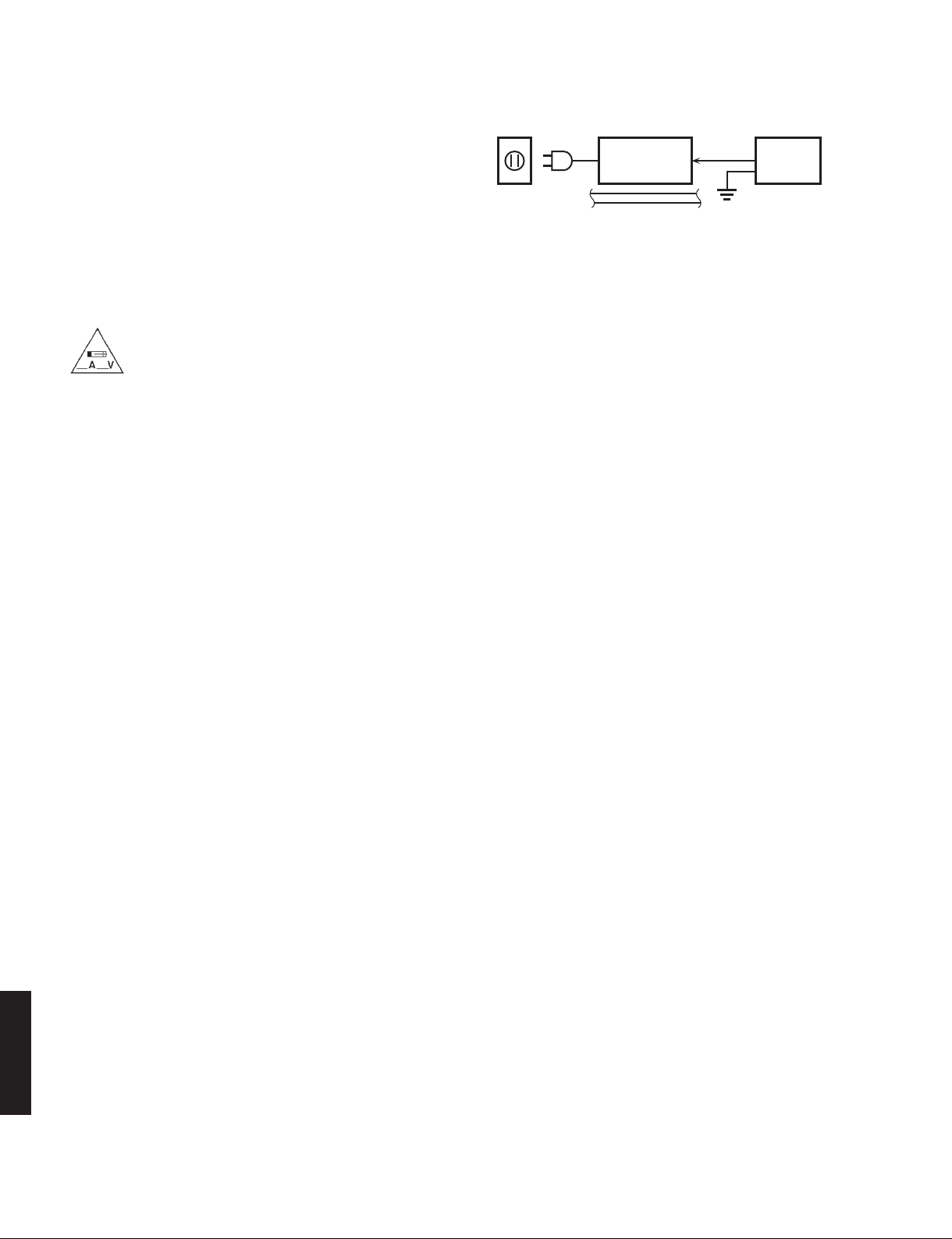
2. Leakage Current Measurement (For 120V Models Only)
When service has been completed, it is imperative to verify
that all exposed conductive surfaces are properly insulated
from supply circuits.
• Meter impedance should be equivalent to 1500 ohms shunted
by 0.15 μF.
“CAUTION”
“F501: FOR CONTINUED PROTECTION AGAINST RISK OF FIRE, REPLACE ONLY WITH SAME TYPE 4A, 125V
FUSE.”
CAUTION
F501: REPLACE WITH SAME TYPE 4A, 125V FUSE.
ATTENTION
F501: UTILISER UN FUSIBLE DE RECHANGE DE MÉME TYPE DE 4A, 125V.
WALL
OUTLET
• Leakage current must not exceed 0.5mA.
• Be sure to test for leakage with the AC plug in both polarities.
EQUIPMENT
UNDER TEST
INSULATING
TABLE
AC LEAKAGE
TESTER OR
EQUIVALENT
WARNING: CHEMICAL CONTENT NOTICE!
This product contains chemicals known to the State of California to cause cancer, or birth defects or other reproductive
harm.
DO NOT PLACE SOLDER, ELECTRICAL/ELECTRONIC OR PLASTIC COMPONENTS IN YOUR MOUTH FOR ANY REASON
WHATSOEVER!
Avoid prolonged, unprotected contact between solder and your skin! When soldering, do not inhale solder fumes or
expose eyes to solder/flux vapor!
If you come in contact with solder or components located inside the enclosure of this product, wash your hands before
handling food.
About lead free solder
All of the P.C.B.s installed in this unit and solder joints are soldered using the lead free solder.
Among some types of lead free solder currently available, it is recommended to use one of the following types for the
repair work.
• Sn + Ag + Cu (tin + silver + copper)
• Sn + Cu (tin + copper)
• Sn + Zn + Bi (tin + zinc + bismuth)
Caution:
As the melting point temperature of the lead free solder is about 30°C to 40°C (50°F to 70°F) higher than that of the lead
solder, be sure to use a soldering iron suitable to each solder.
DRX-730/NX-E700
2

DRX-730/NX-E700
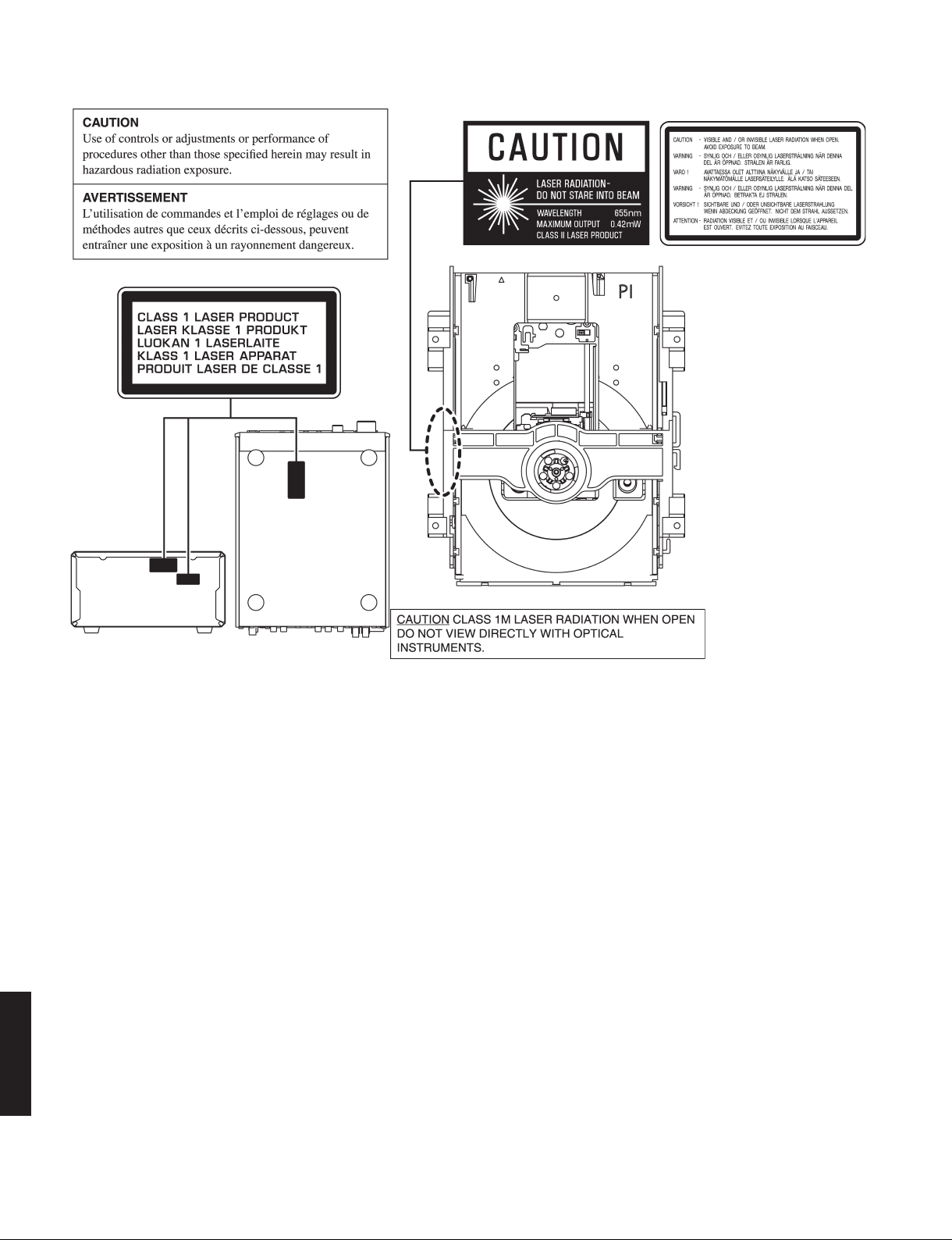
WARNING: Laser Safety
This product contains a laser beam component. This component may emit invisible, as well as visible radiation,
which may cause eye damage. To protect your eyes and skin from laser radiation, the following precautions must
be used during servicing of the unit.
1) When testing and/or repairing any component within the product, keep your eyes and skin more than 30 cm/1 feet
away from the laser pick-up unit at all times. Do not stare at the laser beam at any time.
2) Do not attempt to readjust, disassemble or repair the laser pick-up, unless noted elsewhere in this manual.
3) CAUTION: Use of controls, adjustments or performance of procedures other than those specified herein may result in
hazardous radiation exposure.
Laser Emitting conditions:
1) When the Top Cover is removed, and the STANDBY/ON SW is turned to the “ON” position, the laser component will
emit a beam for several seconds to detect if a disc is present. During this time (5-10 sec.) the laser may radiate
through the lens of the laser pick-up unit. Do not attempt any servicing during this period!
If no disc is detected, the laser will stop emitting the beam. When a disc is loaded, you will not be exposed to any
laser emissions.
2) The laser power level can be adjusted with the VR on the pick-up PWB, however, this level has been set by the factory
prior to shipping from the factory. Do not adjust this laser level control unless instruction is provided elsewhere in this
manual. Adjustment of this control can increase the laser emission level from the device.
Laser Diode Properties
Type: Semiconductor laser AlGaInP
Wave length: 655 nm (DVD)
790 nm (VCD/CD)
Output Power: 5 mW (DVD)
7 mW (VCD/CD)
Beam divergence: 20 degree
DRX-730/NX-E700
3
DRX-730/NX-E700
U, C models T, K, A, G, F, L, V models
Warning for power supply
The primary side of the power supply carries live mains voltage when the player is connected to the mains even
when the player is switched off !
This primary area is not shielded so it is possible to accidentally touch copper tracks and/or components when servicing
the player.
Service personnel have to take precautions to prevent touching this area or components in this area.
Note:
The screws on the DVD mechanism may never be touched, removed or re-adjusted.
Handle the DVD mechanism with care when the unit has to be exchanged!
The DVD mechanism is very sensitive for dropping or giving shocks.
DRX-730/NX-E700
4
DRX-730/NX-E700
■ PREVENTION OF ELECTROSTATIC DISCHARGE
Some semiconductor (solid state) devices can be damaged easily by static electricity. Such components commonly are
called Electrostatically Sensitive (ES) Devices. Examples of typical ES devices are integrated circuits and some field-effect
transistors and semiconductor “chip” components. The following techniques should be used to help reduce the incidence
of component damage caused by electro static discharge (ESD).
1. Immediately before handling any semiconductor component or semiconductor-equipped assembly, drain off any ESD
on your body by touching a known earth ground. Alternatively, obtain and wear a commercially available discharging
ESD wrist strap, which should be removed for potential shock reasons prior to applying power to the unit under test.
2. After removing an electrical assembly equipped with ES devices, place the assembly on a conductive surface such as
aluminum foil, to prevent electrostatic charge buildup or exposure of the assembly.
3. Use only a grounded-tip soldering iron to solder or unsolder ES devices.
4. Use only an anti-static solder removal device. Some solder removal devices not classified as “anti-static (ESD protected)” can generate electrical charge sufficient to damage ES devices.
5. Do not use freon-propelled chemicals. These can generate electrical charges sufficient to damage ES devices.
6. Do not remove a replacement ES device from its protective package until immediately before you are ready to install it.
(Most replacement ES devices are packaged with leads electrically shorted together by conductive foam, aluminum foil
or comparable conductive material).
7. Immediately before removing the protective material from the leads of a replacement ES divice, touch the protective
material to the chassis or circuit assembly into which the device will be installed.
CAUTION: Be sure no power is applied to the chassis or circuit, and observe all other safety precautions.
8. Minimize bodily motions when handling unpackaged replacement ES devices. (Otherwise harmless motion such as
brushing together of your fabric clothes or lifting of your foot from a carpeted floor can generate static electricity (ESD)
sufficient to damage an ES device).
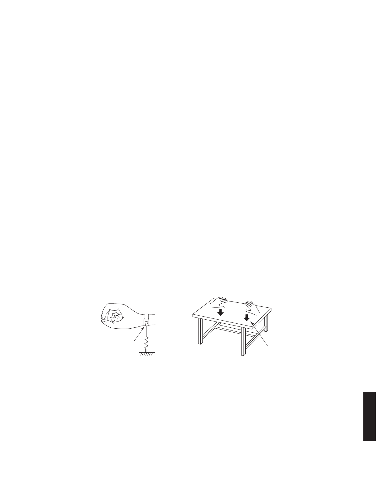
Grounding for electrostatic breakdown prevention
1. Human body grounding.
Use the antistatic wrist strap to discharge the static electricity from your body.
2. Work table grounding.
Put a conductive material (sheet) or steel sheet on the area where the optical pickup is placed and ground the sheet.
Caution:
The static electricity of your clothes will not be grounded through the wrist strap. So take care not to let your clothes touch
the optical pickup.
Anti-static wrist strap
1M-ohms
Conductive material
(sheet) or steel sheet
DRX-730/NX-E700
5
DRX-730/NX-E700
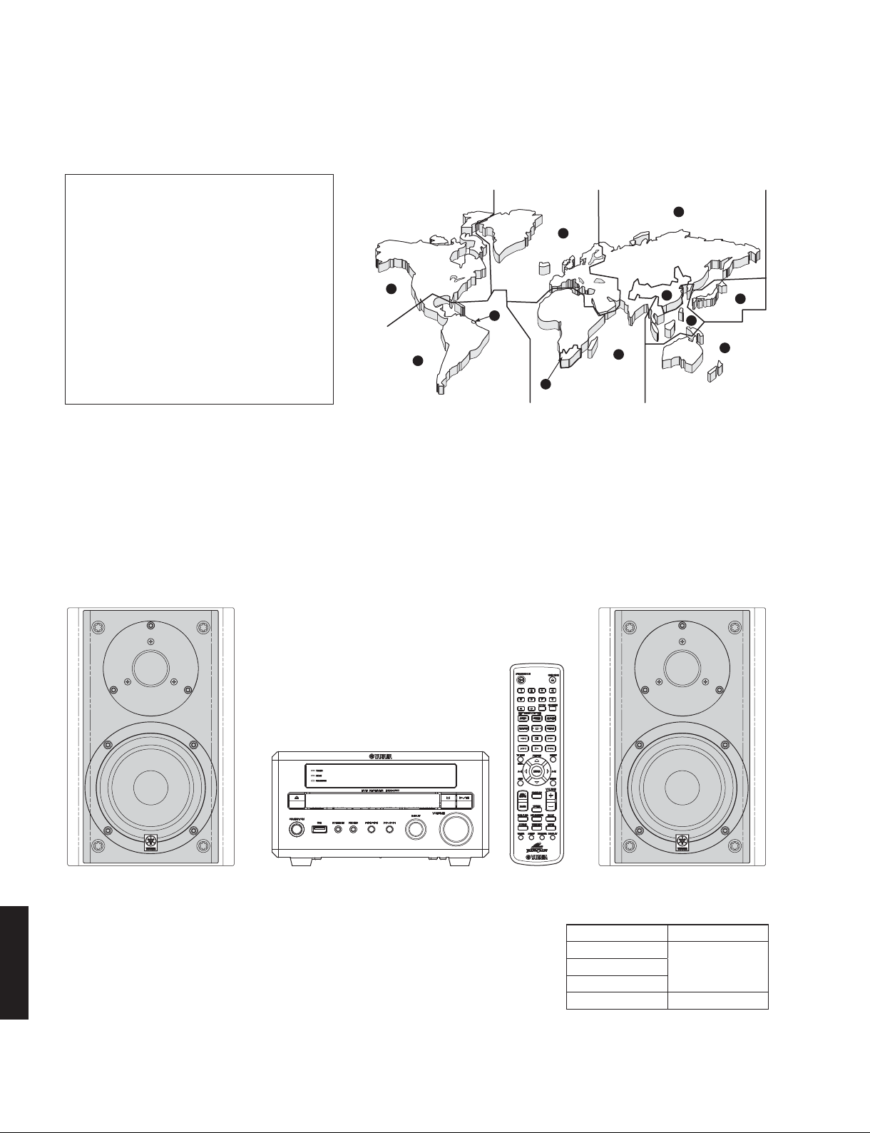
■ REGION MANAGEMENT INFORMATION
Region Management Information: This DVD player is designed and manufactured to respond to the Region
Management Information that is recorded on a DVD disc. If the Region number described on the DVD disc does
not correspond to the Region number of this DVD player, this DVD player cannot play this disc.
This product incorporates copyright
protection technology that is protected
by method claims of certain U.S. patents
and other intellectual property rights
owned by Macrovision Corporation
and other rights owners. Use of this
copyright protection technology must be
authorized by Macrovision Corporation,
and is intended for home and other
limited viewing uses only unless
otherwise authorized by Macrovision
Corporation. Reverse engineering or
disassembly is prohibited.
2
1
2
4
2
5
5
6
3
2
4
■ SYSTEM COMPOSITION
The MCR-730 consists of the DRX-730 and the NX-E700.
▼ NX-E700 ▼ NX-E700
▼ DRX-730
Color variations:
DRX-730 NX-E700
Gold color
Black colorBlack color
Silver color
DRX-730/NX-E700
White color White color
6
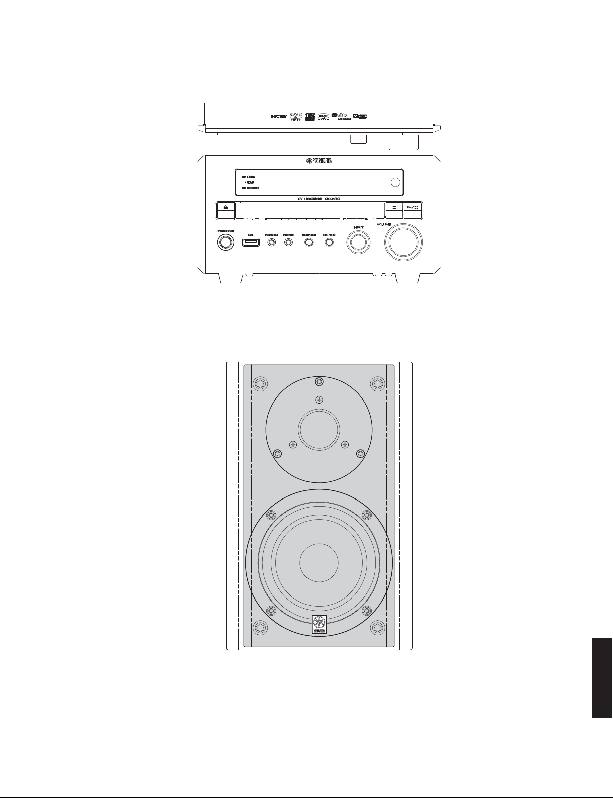
■ FRONT PANELS
DRX-730/NX-E700
DRX-730 (U, C, T, K, A, G, F, L, V models)
Top view
NX-E700 (U, C, T, K, A, G, F, L, V models)
DRX-730/NX-E700
7
DRX-730/NX-E700
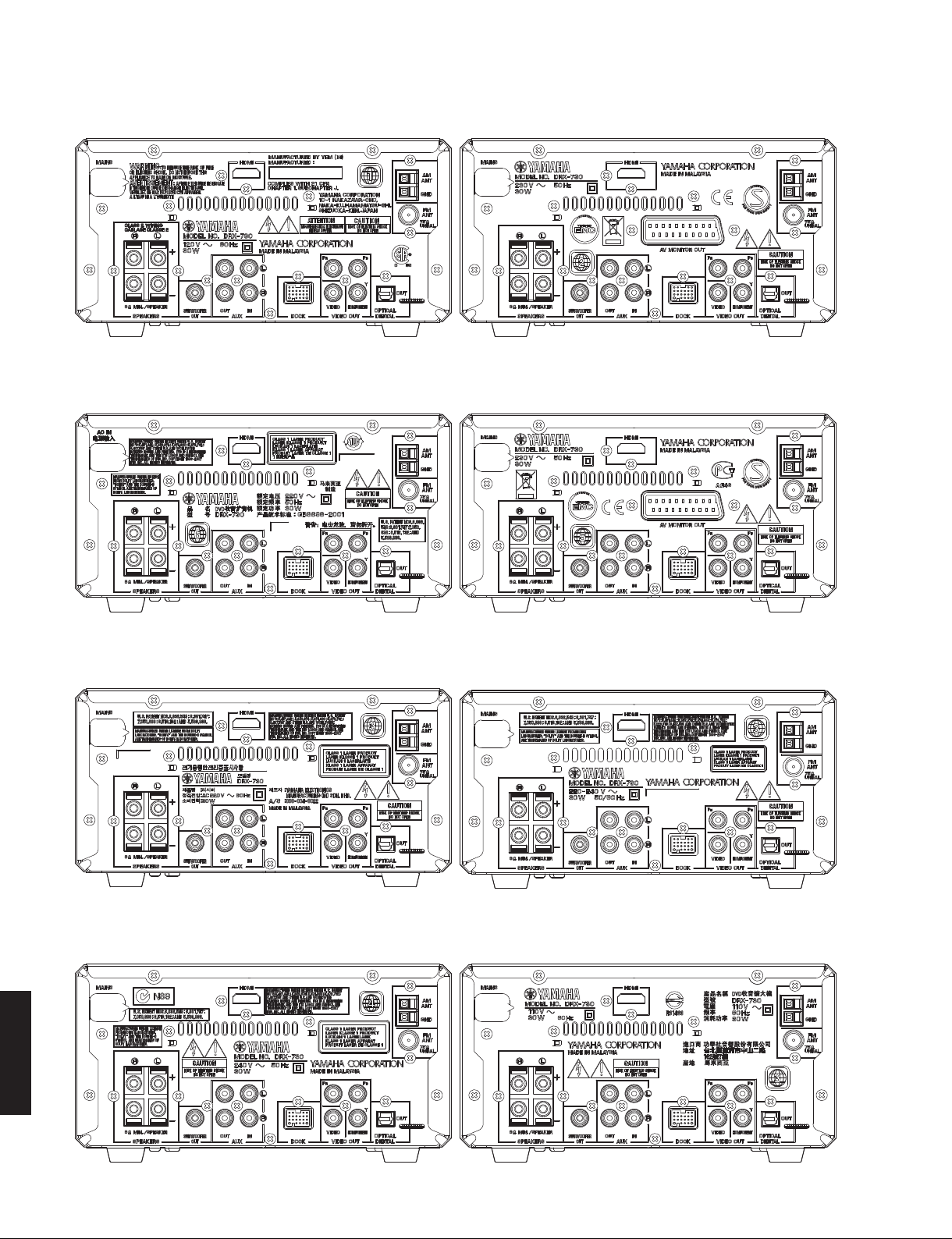
■ REAR PANELS
DRX-730 (U, C models)
DRX-730 (T model) DRX-730 (F model)
DRX-730 (G model)
DRX-730 (K model) DRX-730 (L model)
DRX-730 (A model) DRX-730 (V model)
DRX-730/NX-E700
8
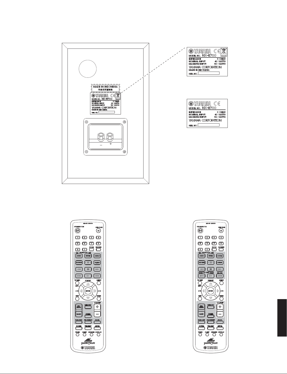
NX-E700
DRX-730/NX-E700
U, C, K, A, G, F, L, V models
T model
T model
■ REMOTE CONTROL PANELS
U, C, K, A, L, V models G, F models
DRX-730/NX-E700
9

DRX-730/NX-E700
■ SPECIFICATIONS
■ Amplifier Section
Maximum Power (JEITA, 6 ohms, 1 kHz, 10 % THD)
SP OUT ........................................................... 30 W + 30 W
Minimum RMS Output Power (6 ohms, 1 kHz, 0.9 % THD)
SP OUT ........................................................... 20 W + 20 W
Input Sensitivity/Input Impedance (1 kHz, 20 W)
AUX, PORTABLE ..................................... 400 mV/47 k-ohms
Maximum Input Signal Level (1 kHz, 0.5 % THD)
AUX, PORTABLE .............................................2.2 V or more
Output Level/Output Impedance (400 mV)
REC OUT (1 kHz) .................................. 400 mV/1.2 k-ohms
WOOFER PRE OUT (50 Hz) ........................ 2.0 V/1 k-ohms
HEADPHONE (1 kHz, 32 ohms) ............. 660 mV/100 ohms
Frequency Response (AUX, PORTABLE, 10 to 22 kHz)
SP OUT ..................................................................... 0/-3 dB
Signal to Noise Ratio (AUX, PORTABLE, IHF-A)
SP OUT (Input shorted 400 mV) ..................95 dB or more
Total Harmonic Distortion
(AUX, PORTABLE, 20 kHz-LPF, 1 kHz, 1 W)
SP OUT ..........................................................0.05 % or less
Tone Control Characteristics
BASS
TREBLE
■ Tuner Section
Tuning Range
FM
AM
■ DVD Section
Output Level (DVD/VIDEO, CD/CD-DA)
REC OUT (1 kHz, 0 dB) ........................................ 2 ±0.3 V
Signal to Noise Ratio (DVD/VIDEO, CD/CD-DA)
REC OUT (Weighted) ..................................100 dB or more
Dynamic Range
REC OUT
Harmonic Distortion + Noise (DVD/VIDEO, CD/CD-DA)
REC OUT .....................................................0.005 % or less
Frequency Response
PRE OUT
DRX-730/NX-E700
Video Output
Composite .................................................1 Vp-p (75 ohms)
Y Output/Component Video Output
..................................................................1 Vp-p (75 ohms)
DRX-730
SP OUT (100 Hz) ................................................... ±10 dB
SP OUT (10 kHz) ................................................... ±10 dB
U, C models ......................................... 87.5 to 107.9 MHz
T, K, A, G, F models ....................... 87.50 to 108.00 MHz
L, V models .............87.5 to 108.0 / 87.50 to 108.00 MHz
U, C models ........................................... 530 to 1,710 kHz
T, K, A, G, F models ............................. 531 to 1,611 kHz
L, V models ....................530 to 1,710 / 531 to 1,611 kHz
DVD, 48 kHz, 24 bit ...................................95 dB or more
CD-DA/VIDEO, CD ......................................95 dB or more
CD-DA/VIDEO, CD ...................................10 Hz to 20 kHz
DVD, 48 kHz, sampling ...........................10 Hz to 22 kHz
DVD, 96 kHz, sampling ...........................10 Hz to 44 kHz
Pb Output/Component Video Output
...............................................................0.7 Vp-p (75 ohms)
Pr Output/Component Video Output
...............................................................0.7 Vp-p (75 ohms)
RGB AV MONITOR OUT (SCART) Output [G, F models]
...............................................................0.7 Vp-p (75 ohms)
■ Input/Output Section
Input Terminal
Analog audio ............................... AUX L/R (pin jack – rear)
PORTABLE (mini jack – front)
Other ...........................................USB (USB 1.1, full speed)
DOCK
Output Terminal
Analog audio ................................................ SPEAKERS L/R
PHONES
AUX L/R (REC)
SUBWOOFER
Digital audio ........................................................... OPTICAL
Video .......................................................VIDEO (composite)
COMPONENT (Y, P
HDMI
AV MONITOR OUT (SCART) (G, F models)
■ General
Power Supply
U, C models ..................................................... AC 120 V, 60 Hz
T model ............................................................ AC 220 V, 50 Hz
K model ............................................................ AC 220 V, 60 Hz
A model ............................................................ AC 240 V, 50 Hz
G, F models ..................................................... AC 230 V, 50 Hz
L model ................................................AC 220-240 V, 50/60 Hz
V model ............................................................ AC 110 V, 60 Hz
Power Consumption
......................................................................................30 W
Standby Power Consumption (reference data)
.......................................................................Less than 1 W
Dimensions (W x H x D)
...........215 x 113 x 300 mm (8-7/16" x 4-7/16" x 11-13/16")
Weight
...............................................................2.9 kg (6 lbs. 6 oz.)
Finish
Gold color .......................................................... T, A models
Black color ......................................U, A, G, F, L, V models
Silver color ................................. C, K, A, G, F, L, V models
White color ..........................................C, K, A, G, F models
Accessories
Remote control ................................................................ x 1
Battery (R6, AA, UM-3) ................................................... x 2
Indoor FM antenna (1.4 m) ............................................. x 1
AM loop antenna (1.2 m) ................................................ x 1
Video pin cable (1.5 m) .................................................. x 1
* Specifications are subject to change without notice due to product
improvements.
, PR)
B
10
NX-E700
■ Speaker Section
Type ................................. 2-way bass reflex speaker system
Magnetic shielding type
Driver
Woofer ...........................................11 cm (4-1/2") cone type
Tweeter .............................................2.5 cm (1") dome type
Frequency Response
......................................................60 Hz to 28 kHz (-10dB)
Impedance ...................................................................6 ohms
Nominal Input ................................................................40 W
Maximum Input ............................................................ 110 W
Sensitivity ..................................................... 85 dB/2.83 V/m
Crossover Frequency ................................................... 3 kHz
Input Terminal ......................................... Screw/Banana type
Dimensions (W x H x D) .......165 mm x 255 mm x 183 mm
(6-1/2" x 10-1/16" x 7-3/16")
Weight ....................................................3.4 kg (7 lbs. 8 oz.)
Finish
Black color ........................ U, C, T, K, A, G, F, L, V models
White color ..........................................C, K, A, G, F models
Accessory ...................................... Speaker cable (4 m) x 1
* Specifications subject to change without prior notice.
DRX-730/NX-E700
U .......................U.S.A. model
C .................Canadian model
T .................... Chinese model
K .....................Korean model
A ................Australian model
DivX, DivX Ultra Certified, and associated logos
are trademarks of DivX, Inc. and are used under
license.
Manufactured under license from Dolby Laboratories.
Dolby and the double-D symbol are trademarks of Dolby
Laboratories.
DTS and DTS 2.0 + Digital Out are registered trademarks
and the DTS logos and Symbol are trademarks of DTS,
Inc.
“HDMI”, the “HDMI” logo, and “High-Definition Multimedia
Interface” are trademarks or registered trademarks of
HDMI Licensing LLC.
MPEG Layer-3 audio decoding technology licensed from Fraunhofer
IIS and Thomson multimedia.
Windows Media is either a registered trademark or trademark of
Microsoft Corporation in the United States and/or other countries.
G .................European model
F .................... Russian model
L .................Singapore model
V ..................... Taiwan model
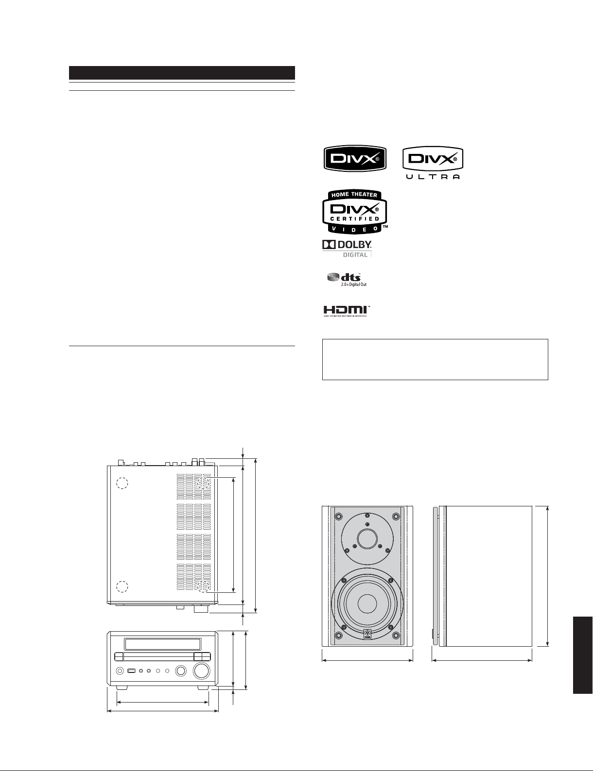
• DIMENSIONS
DRX-730
14 (9/16")
219 (8-5/8")
15 (9/16")
105 (4-1/8")
300 (11-13/16")
271 (10-11/16")
113 (4-7/16")
NX-E700
255 (10-1/16")
DRX-730/NX-E700
165 (6-1/2") 183 (7-3/16")
175 (6-7/8")
215 (8-7/16")
8
(5/16")
Unit: mm (inch)
11
DRX-730/NX-E700
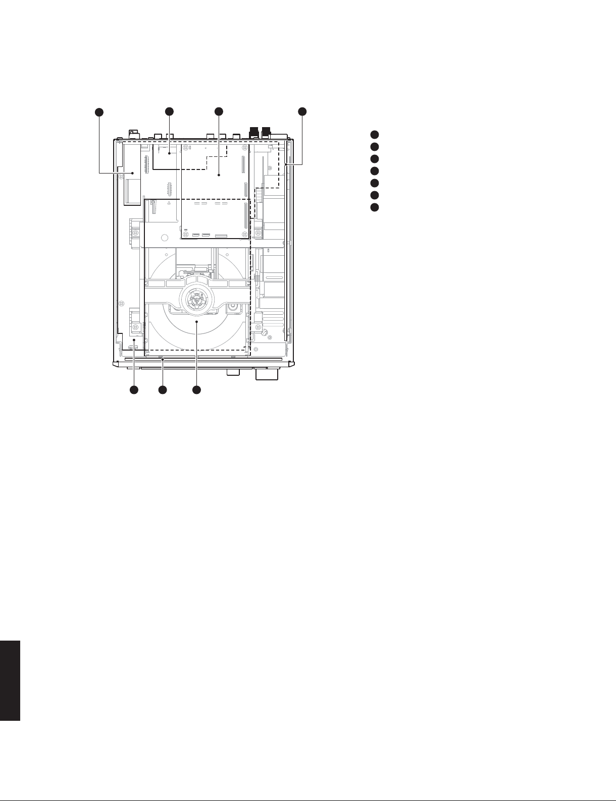
■ INTERNAL VIEW
Top view
1
5 67
2
3
4
1
AM/FM TUNER
2
MAIN (2) P.C.B. (G, F models)
3
DVD MODULE P.C.B.
4
SUB (1) P.C.B.
5
MAIN (1) P.C.B.
6
SUB (2) P.C.B.
7
DVD MECHANISM ASS’Y
DRX-730/NX-E700
12
DRX-730/NX-E700
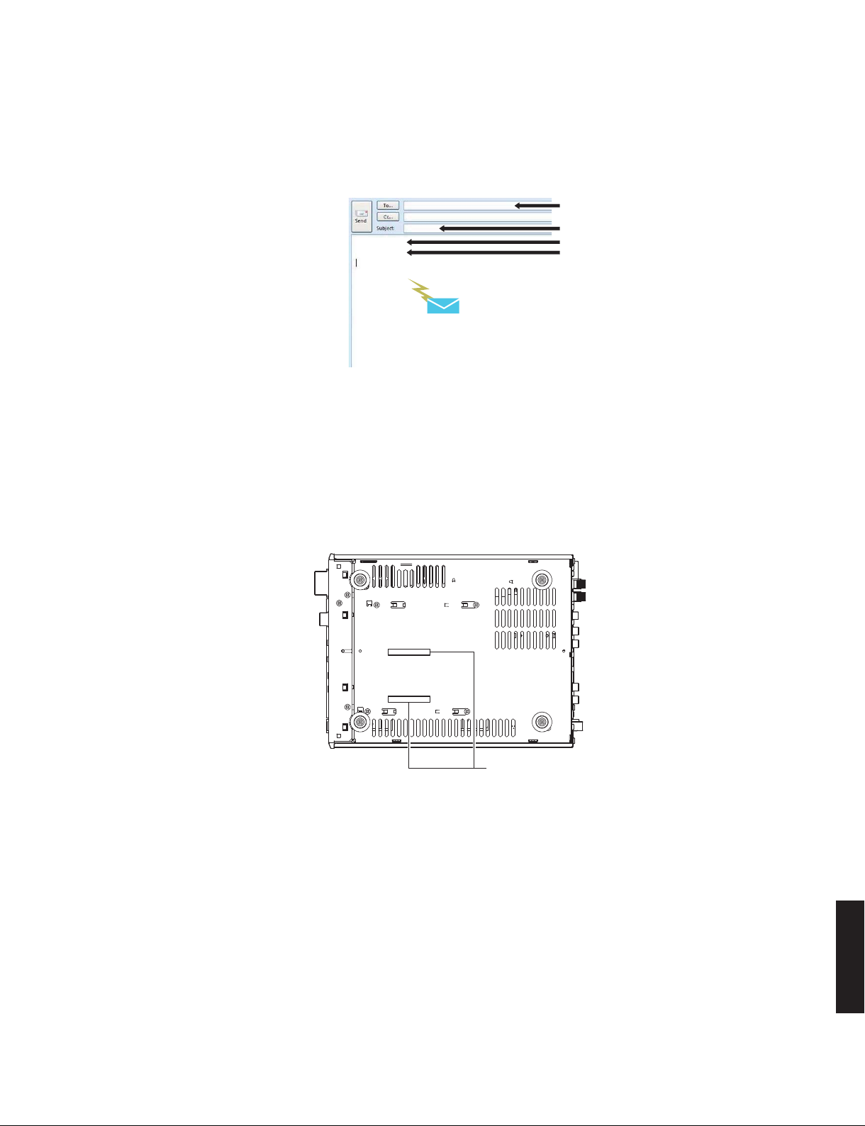
■ SERVICE PRECAUTIONS
When DVD MODULE P.C.B. of this unit is replaced, the serial number and new ID number (device key) must be reported to
YCJ (Yamaha Corporation Japan) by email. (Fig. 1)
Email: ycav-keycontrol@gmx.yamaha.com
ycav-keycontrol@gmx.yamaha.com
DRX-730
Y015018XZ
008000155
Send this email to YCJ
Fig. 1
● Check the Serial Number
The serial number “SER.NO.xxxxxxxx” can be found at the bottom of this unit. (Fig.2)
Bottom view
ycav-keycontrol@gmx.yamaha.com
Model name
Serial number of DRX-730
ID number (device key)
Front side
U, C, G, F, V models
Rear side
T, K, A, L models
Serial number
Fig. 2
DRX-730/NX-E700
13
DRX-730/NX-E700
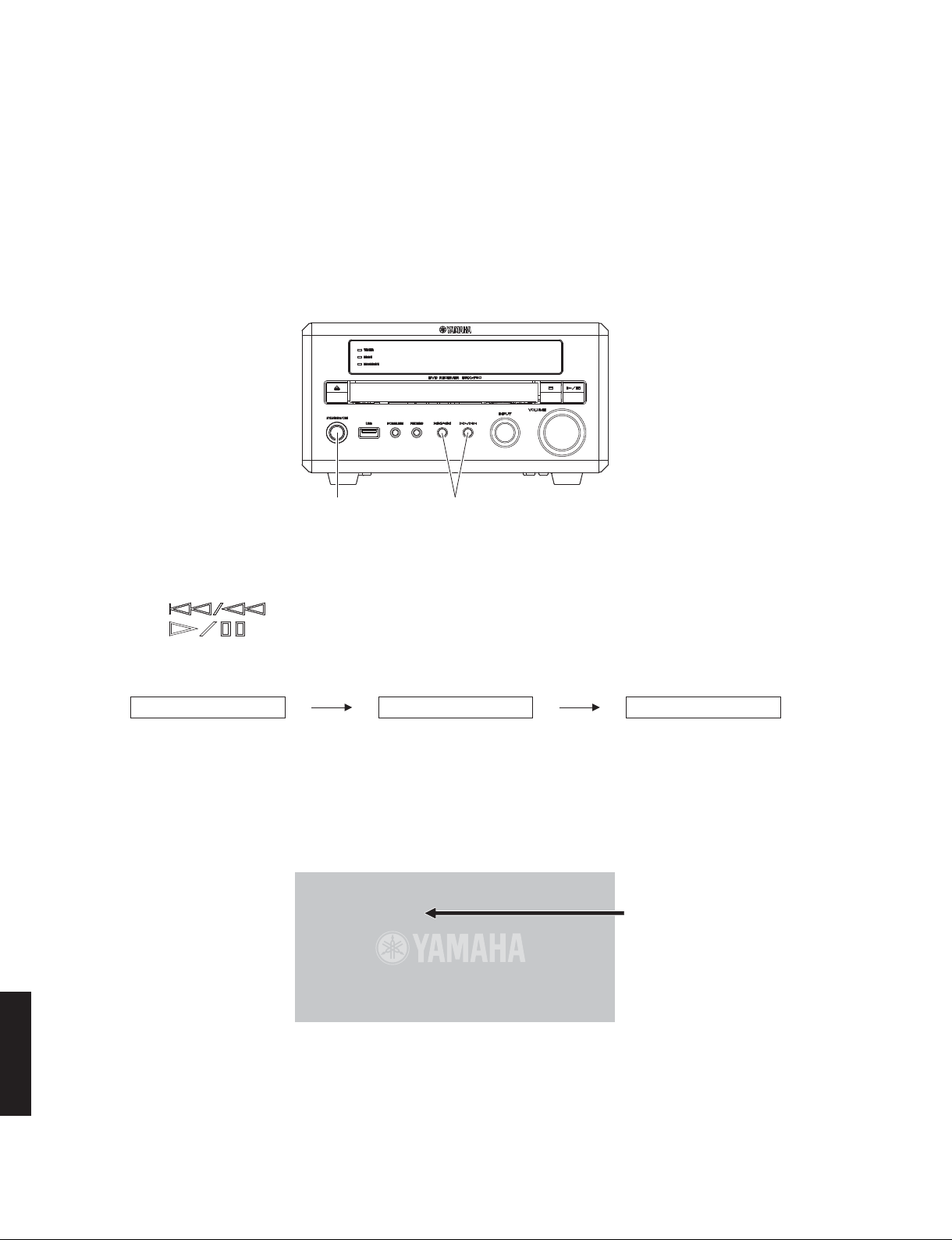
● Check the New ID Number (Device key)
Connection
Connect the VIDEO OUT terminal of this unit to the VIDEO IN terminal of the TV monitor with a video pin cable.
Operation Procedure
Perform following steps while watching the TV monitor screen and using the keys of this unit.
1. While pressing those 2 keys of this unit as indicated in the figure below, press the “STANDBY/ON” key to turn on
the power.
The self-diagnostic function is activated. (Fig. 3)
“STANDBY/ON” key Turn on the power while pressing these keys.
Fig. 3
2. Press “ (Previous/Rewind)” key once to select main menu 11 DVD WRITE ID.
3. Press “
(Play/Pause)” key once to select sub-menu 11-2 DVD CLEAR ID.
Wait about 15 seconds.
Self-diagnostic function starting display Main menu 11 – DVD WRITE ID sub-menu 11-2 – DVD CLEAR ID
VER,A34S:D2E1 DVDWRITEID DVDCLEARID
Fig. 4
4. New ID number (device key) will appear on the TV monitor screen as shown below.
Note: While the ID number (device key) is displayed, never operate any keys of the remote control.
(Player's ID Number Setting)
ID Number ?
008000155
Compare
*********
<CLEAR> Exit
New ID number (device key)
* The displayed “008000155” is an
example.
Input ID Number !
Fig. 5
DRX-730/NX-E700
5. To exit the self-diagnostic function, press “STANDBY/ON” key to turn off the power.
14
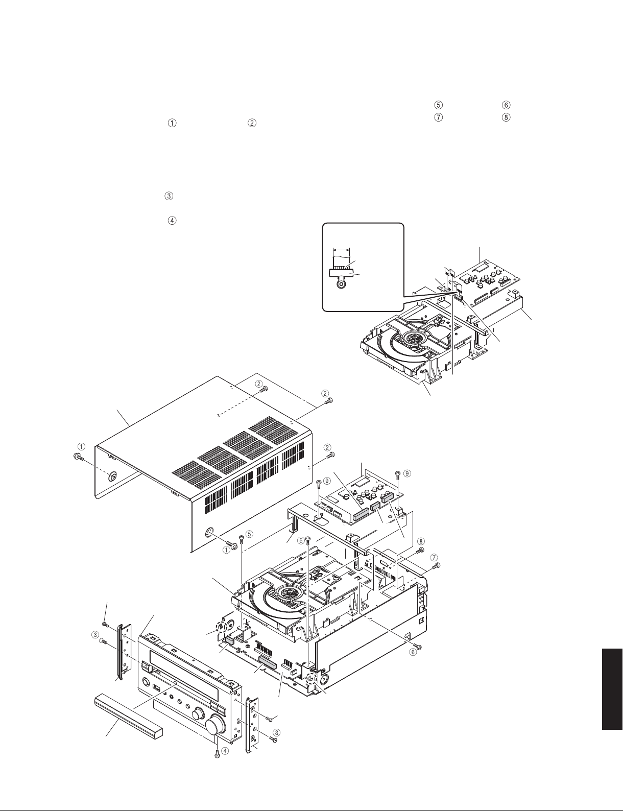
■ DISASSEMBLY PROCEDURES
(Remove parts in the order as numbered.)
Disconnect the power cable from the AC outlet.
1. Removal of Top Cover
a. Remove 2 screws ( ) and 4 screws ( ). (Fig. 1)
b. Slide the top cover rearward to remove it. (Fig. 1)
2. Removal of Front Panel Unit
a. Open the disc tray, remove the lid and close the disc
tray. (Fig. 3)
b. Remove 2 screws (
side panels. (Fig. 1)
c. Remove 3 screws (
d. Release 2 hooks, pull out the front panel unit forward.
(Fig. 1)
e. Remove CB12 and CB26. (Fig. 1)
), 2 push rivets and then remove 2
). (Fig. 1)
DRX-730/NX-E700
3. Removal of DVD Mechanism Ass’y and DVD
Module P.C.B.
a. Remove 4 screws ( ) and screw ( ). (Fig. 1)
b. Remove 3 screws (
c. Remove CN962, CN967 and CN968. (Fig. 1)
d. Remove the DVD mechanism ass’y and DVD module
P.C.B. together with support P.C.B.. (Fig. 1)
e. Remove CN964 and CN965. (Fig. 1)
f. Remove CN966, and ground the terminal face of the
flexible flat cable with a clip or the like. (Fig. 1)
g. Remove the DVD mechanism ass’y. (Fig. 1)
13 mm
(1/2")
Terminal side
) and screw ( ). (Fig. 1)
DVD module P.C.B.
Top cover
P. C . B .
support
Clip
Use a clip or other item
to ground the unit.
DVD module P.C.B.
CB968
CB962
CB967
CB965
Support P.C.B.
CB966
CB964
DVD mechanism ass'y
Push rivet
Side panel
Lid
DVD mechanism ass'y
Front panel unit
Hook
CB12
CB26
MAIN (1) P.C.B.
Push rivet
Side panel
DRX-730/NX-E700
Hook
Fig. 1
15
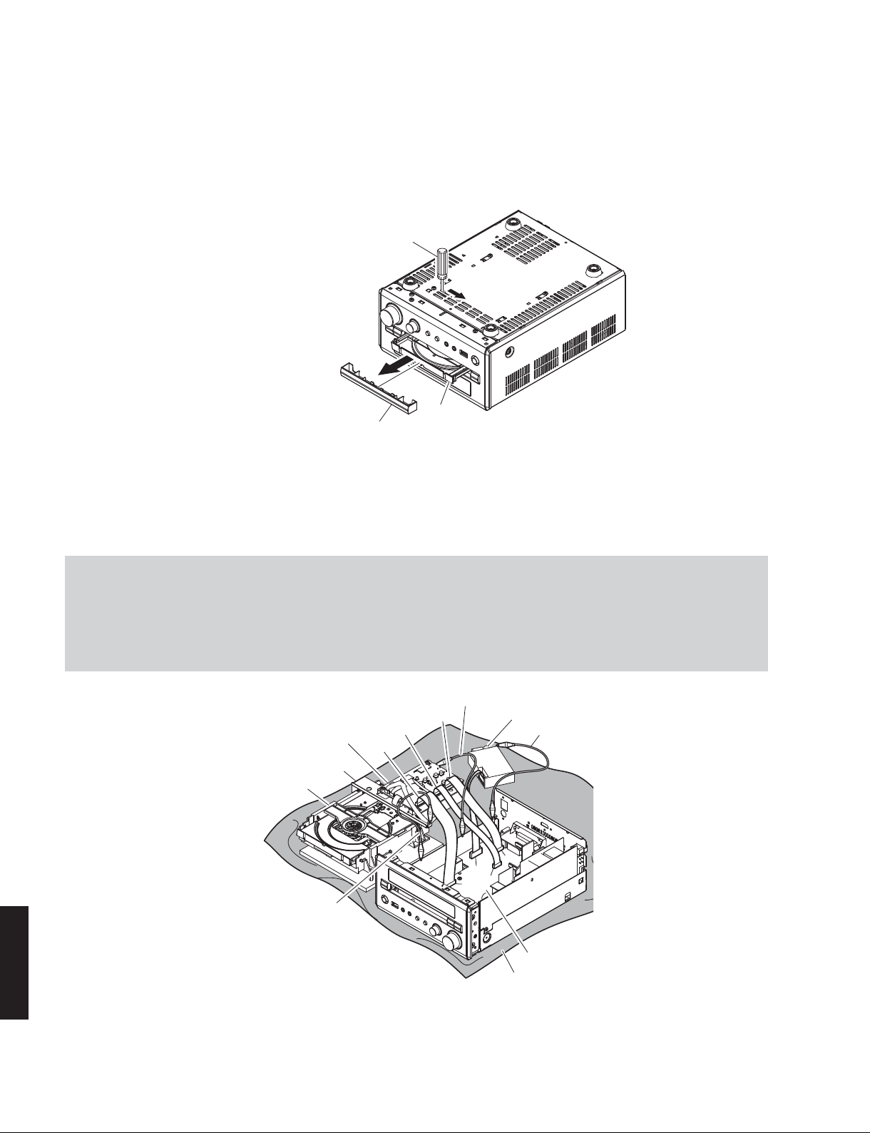
DRX-730/NX-E700
● How to manually eject the disc tray
a. Move the slider in the direction indicated in the figure below with a screwdriver until the disc tray is ejected. (Fig. 2)
Note: An Allen hex socket screwdriver 2.5 mm is recommended for this operation.
b. Gently pull the disc tray out.
(An Allen hex socket screwdriver 2.5 mm)
Screwdriver
Disc tray
Lid
Fig. 2
When checking the P.C.B.s:
• Spread the rubber sheet and the cloth. Then place this unit on the cloth and check it. (Fig. 3)
• Reconnect all cables (connectors) that have been disconnected.
• When connecting the flexible flat cable, be careful with polarity.
• Connect the ground point of the DVD module P.C.B., AM/FM tuner and P.C.B. support to the chassis with a ground
lead or the like. (Fig. 3)
Ground lead
CB967
DVD module P.C.B.
P.C.B. support
DVD mechanism ass'y
Ground lead
DRX-730/NX-E700
CB962
CB968
CB11
Fig. 3
AM/FM tuner
Ground lead
CB7
CB4
CB9
MAIN (1) P.C.B.
Rubber sheet and cloth
16

■ UPDATING FIRMWARE
Writing to the microprocessor
After replacing the following parts update the latest firmware according to the following procedure.
MAIN P.C.B.
Microprocessor (IC11) of MAIN P.C.B.
DRX-730/NX-E700
Required tools
●
• Program downloader program
........................................................ FlashSta.exe
• Firmware
................................................... DRX730_vx.mot
...................................................... DRX730_vx.id
• RS232C cross cable “D-sub 9 pin female”
(Specifications)
Pin No.2 RxD Pin No.2 RxD
Pin No.3 TxD Pin No.3 TxD
Pin No.5 GND Pin No.5 GND
Pin No.7 RTS Pin No.7 RTS
Pin No.8 CTS Pin No.8 CTS
• RS232C conversion jig (Part No.: AAX77610)
Confirmation of Firmware Version and Checksum
●
Before and after writing to the microprocessor, check the firmware version and checksum with the self-diagnostic
function menu.
Preparation and precautions before starting
●
the operation
• Download firmware downloader program and
firmware from the specified source to the same
folder of the PC.
• Prepare the above specified RS232C cross cable.
• While writing, keep the other application software
on the PC closed.
It is also recommended to keep the software on
the task tray closed as well.
Using the self-diagnostic function menu, check that the firmware is updated successfully.
Start up the self-diagnostic function of this unit and the “1. VERSION/SUM” is displayed.
For more information, see “SELF-DIAGNOSTIC FUNCTION”.
1. VERSION/SUM
VER.B39S:084C
Firmware version and checksum value of microprocessor
The firmware version and checksum value of microprocessor (IC11 MAIN P.C.B.) is displayed.
DRX-730/NX-E700
17
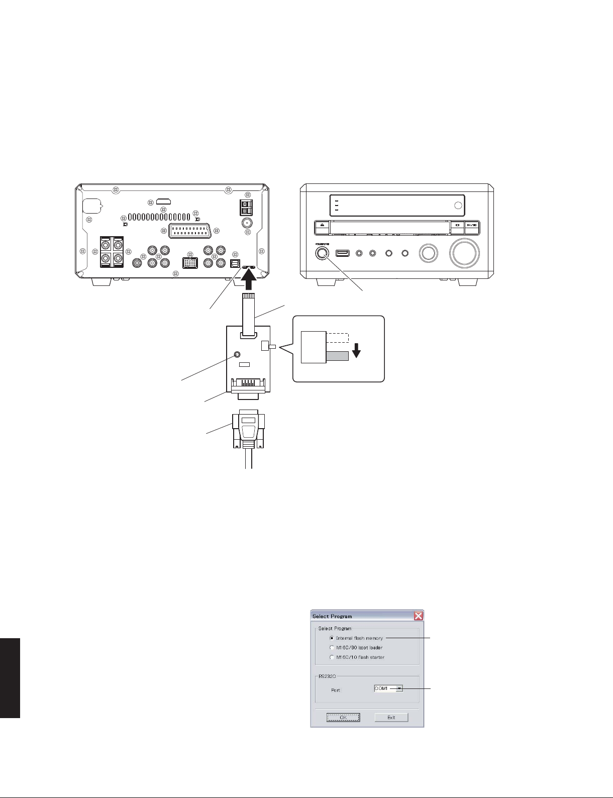
DRX-730/NX-E700
Connection
●
1. Set the switch (SW301) of RS232C conversion adapter to the “FLASH UCOM” side.
2. Connect the writing port of this unit to the serial port (RS232C) of the PC with RS232C cross cable, RS232C conversion jig and flexible flat cable as shown below. (Fig. 1)
Rear side Front side
Writing port
Flexible flat cable 8P
SW301
Reset switch
RS232C conversion jig
RS232C cross cable
"STANDBY/ON" key
OTHE R
FLASH
UCOM
Fig. 1
Operation Procedures
●
1. Connect the power cable of this unit to the AC outlet.
2. While pressing the reset switch of RS232C conversion jig, press the “STANDBY/ON” key of this unit to turn on the
power. (Fig. 1)
3. Start up FlashSta.exe, the screen will appear as shown below. (Fig. 2)
4. Select the port and data to be transmitted. (Fig. 2)
• Select Program
Select Internal flash memory
• RS232C
Select Internal flash memory
Select the port of RS-232C
* For selection of the port, COM1 to 4 can be
used.
As COM5 or higher port cannot be used, se-
DRX-730/NX-E700
lect out of COM 1 to 4 of the setting on the PC
side.
Select the port of RS-232C
18
Fig. 2
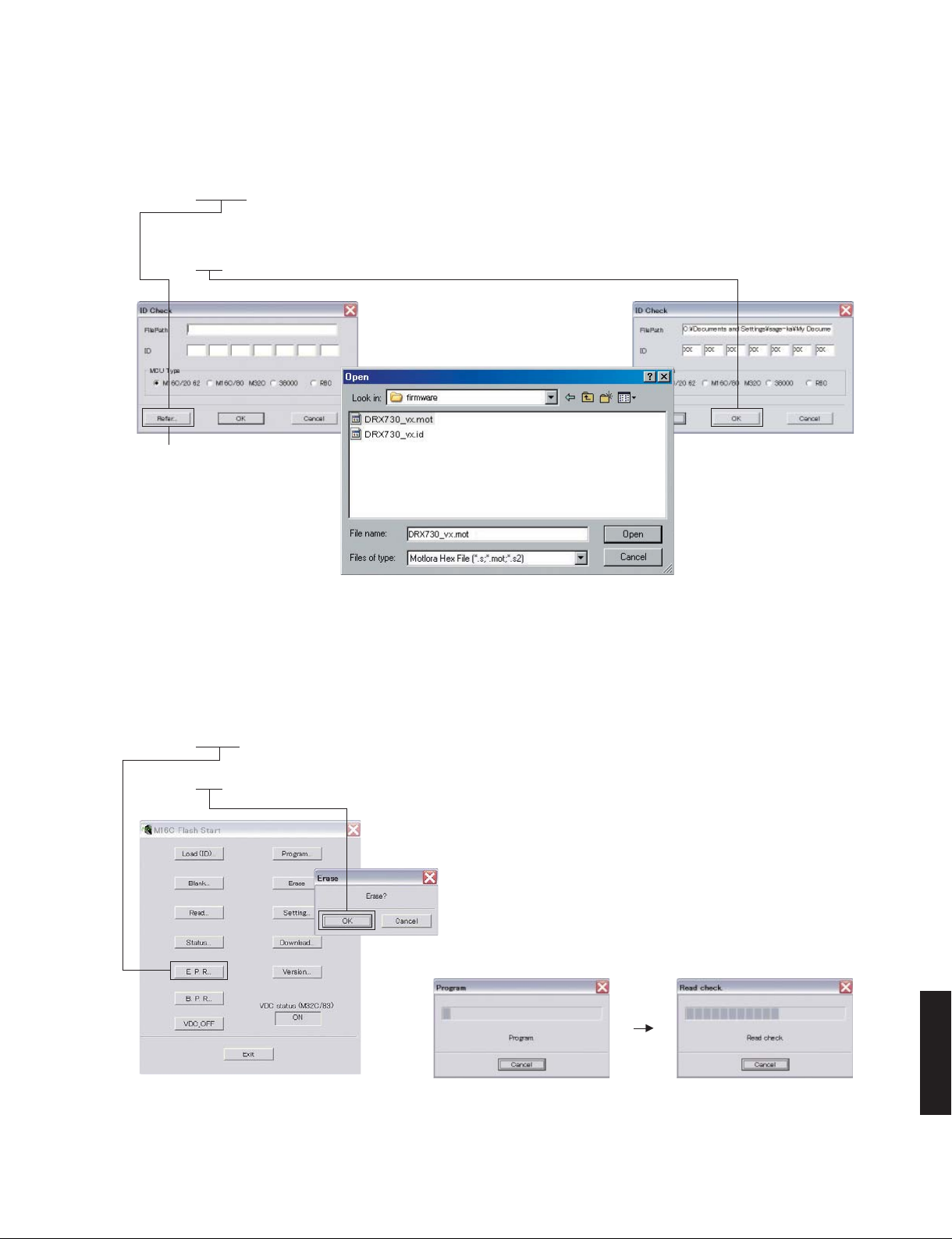
5. Click [Refer...]. And select the firmware name. (Fig. 3)
* The ID code and MCU type are loaded automatically when the file is selected. (Fig. 3)
Click [OK]. (Fig. 3)
Click to open the window
DRX-730/NX-E700
Fig. 3
6. Click [E.P.R.], the screen appears as shown below. (Fig. 4)
Click [OK] to start writing. (Fig. 4)
Writing being executed.
DRX-730/NX-E700
Fig. 4
19
DRX-730/NX-E700
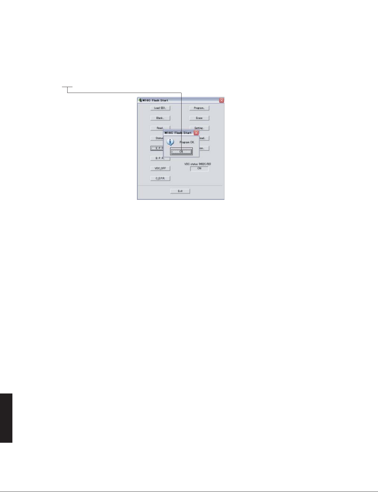
7. When the program transmission is completed, the screen appears as shown below. (Fig. 5)
Click [OK] to end the procedure. (Fig. 5)
Fig. 5
8. Using the self-diagnostic function menu, check that the firmware is updated successfully.
* When the displayed firmware version and checksum are different from written ones, perform the “Writing to the
microprocessor” procedure all over again.
9. End “FlashSta.exe”.
10. Disconnect the power cable of this unit from the AC outlet.
11. Disconnect the RS232C cross cable, RS232C conversion jig and flexible flat cable.
DRX-730/NX-E700
20
DRX-730/NX-E700
Writing to the Module Board
After replacing the Module board with the replacement part, be sure to write the latest firmware.
Required Tools
●
Firmware CD
* To make the firmware CD, download the latest firmware from the specified download source to PC.
When making a firmware CD, set the CD volume label to “PIONEER”.
Firmware: S8CAxxxx.BIN
Confirmation of Firmware Version
●
Before and after the writing firmware to the module board, follow the procedures below to check the firmware version.
1. Connect the VIDEO OUT terminal of this unit to the VIDEO IN terminal of the TV monitor with a video pin cable.
2. Connect the power cable of this unit to the AC outlet.
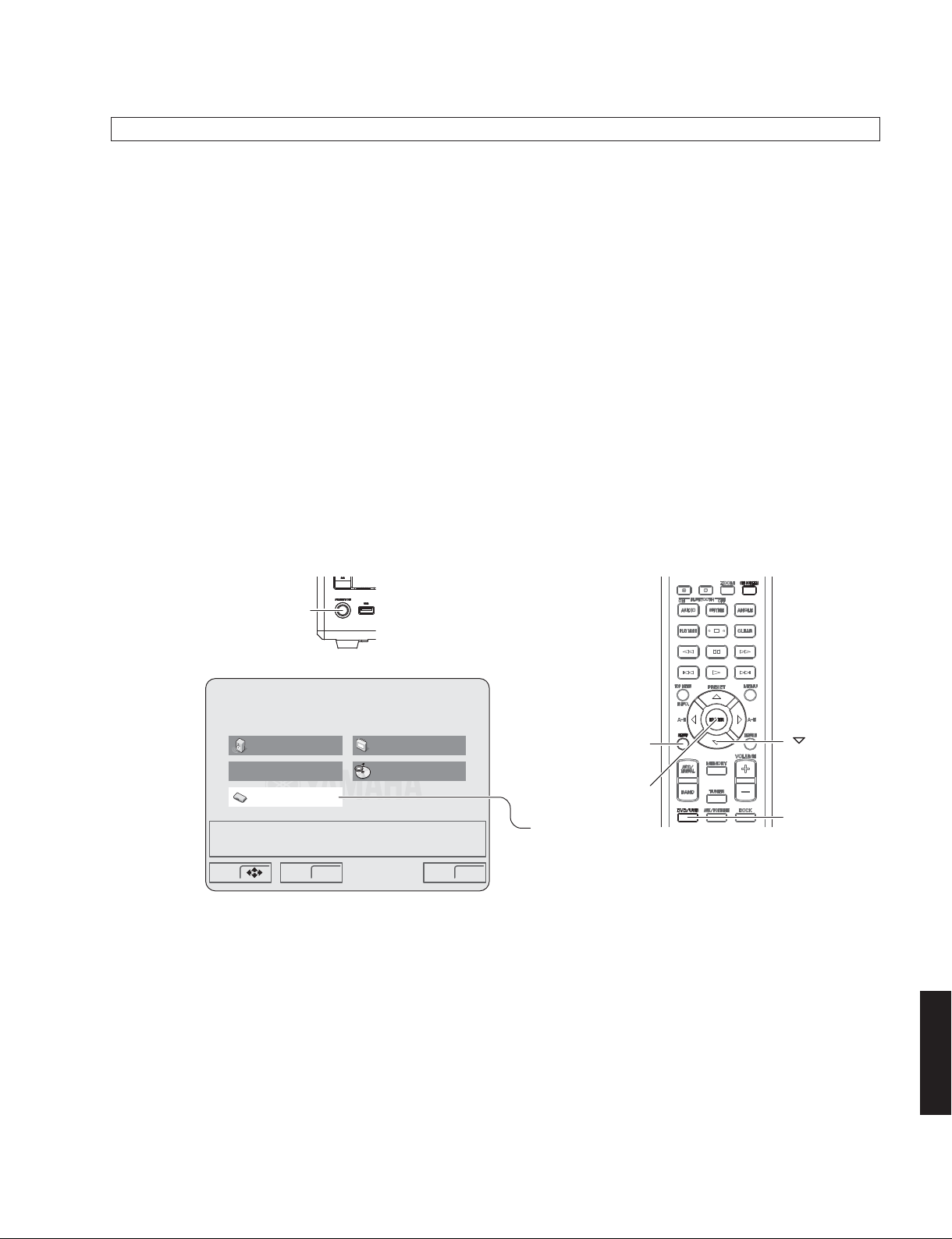
3. Press the “STANDBY/ON” key of this unit to turn on the power. (Fig. 6)
4. Press the “DVD/USB” key on the remote control to select the input DVD. (Fig. 6)
5. Press the “SETUP” key on the remote control. (Fig. 6)
The SETUP menu is displayed on the TV monitor. (Fig. 6)
6. Move the cursor to [Initial Settings] by pressing the “DOWN” key on the remote control and press the “ENTER” key.
(Fig. 6)
This unit
"STANDBY/ON" key
Audio Settings
Play Mode
Initial Settings
Make advanced settings
Move Select ExitENTER SETUP
Video Adjust
Disc Navigator
Fig. 6
"SETUP" key
"ENTER" key
"Initial Settings" select
Remote control
" " (down) key
"DVD/USB" key
DRX-730/NX-E700
21
DRX-730/NX-E700
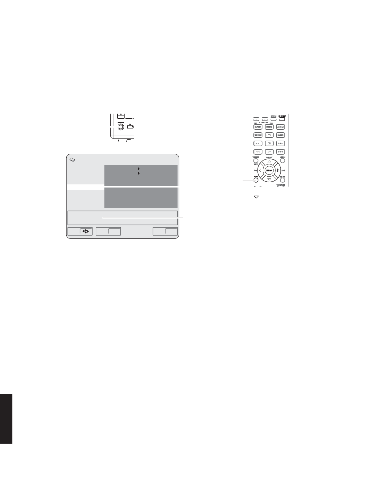
7. Move the cursor to [Options] by pressing the “DOWN” key on the remote control repeatedly and press the “ON
SCREEN” key. (Fig. 7)
The ROM version is displayed. (Fig. 7)
This unit
"ON SCREEN" key
"STANDBY/ON" key
Initial Settings
Digital Audio Out
Video Output
Language
Display
Options
REGION : 1
ROM VERSION : x.xx
Move Select ExitENTER SETUP
Parental Lock
DTS Downmix
DivX(R) VOD
Off(us)
STEREO
"SETUP" key
"Options" select
ROM version is displayed
Fig. 7
8. Press the “SETUP” key on the remote control to end the SETUP procedure. (Fig. 7)
9. Press the “STANDBY/ON” key of this unit to turn off the power. (Fig. 7)
Remote control
" " (down) key
DRX-730/NX-E700
22
 Loading...