

Page 1
6t,)
MM
\llwfrliA
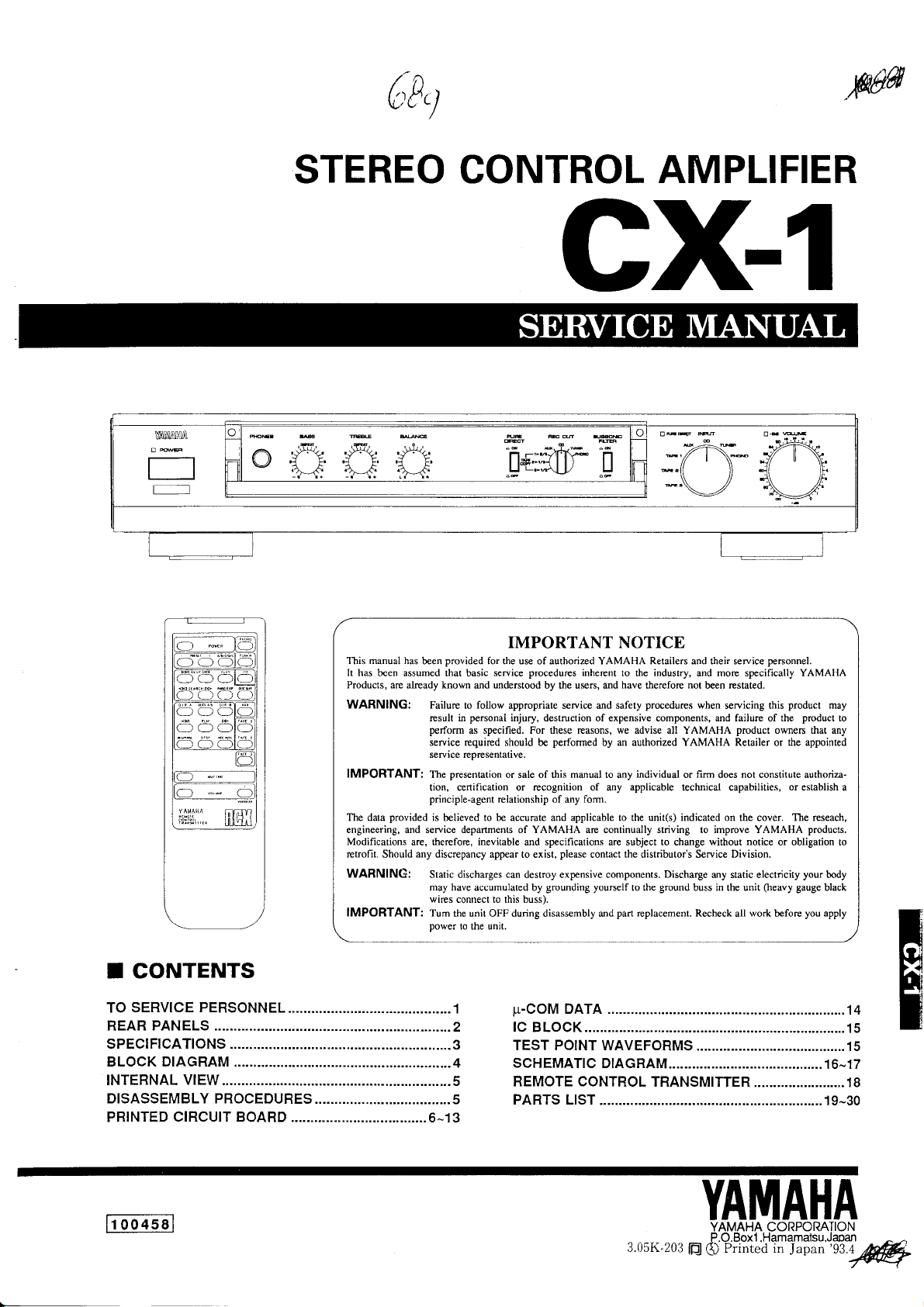
STEREO CONTROL
AMPLIFIER
cx1
oury
l-l ---v'l[''lf\.* n
tffi*'^1 |t I tl
-'-4Ll/
u
H
*'/(
*'\
7N
\v/
rnF'
">2+{tu
'j,/
n
.//
\\*
)
-.11
-\\
-\\
ll \v
,//'
ll-.
t.
)( )(.
lJ
_J
Ul
-)a)a)
]OC
]OC
-tat-
{*tri:"
f[]tH'f;
la-
IMPORTANT NOTICE
This manual has
It has
be€n assumed that basic service
Products, are
WARNING: Failure
IMPORTANT:
provided
The data
engineering, and service depanmenb of YAMAHA arc continually striving to imprcve YAMAHA
Modifications
retrofit.
Should
WARNING:
IMPORTANT: Tum
provided
been
already
result in
perform
seruice required should
seruice representative.
The
tion, cenification or recognition of any
principle-agent
is believed to be accumte and applicable to the unit(s) indicated on
are, tbereforc, inevitable and specifications are subject to change
any
discrepancy appear to exist,
Static discharges can destroy expensive components.
may
wires connect to this buss).
power
for the use of authorized YAMAHA Retailers and their service
known
md
follow
to
personal
as specified. For these reasons, we advise all YAMAHA
presentation
have accumulated by
the unit OFF during disassembly md
to the unit,
procedures inherent
understood
relationship
by the uwrs, and
appropriate service and safety
injury, destruction of expensive components, and failure of the
perfomed
be
or sale of this mmual to any
of any form.
grounding yourself
by an authorized
please
coniact the distributor's Seruice Division.
industry,
to the
have
therefore
procedurcs
individual
applicable
Discharge
ground
to the
part
replacement. Recheck all
not
YAMAHA Retailer
or fim does not constitute authoriza-
technical capabilities,
and morc specifically YAMAHA
bcen restated.
when
without notice
any static electricity
buss in the unit
penonnel.
seruicing this
product
owners that any
or
the cover.
(heavy
work
before
or obligation !o
product
may
product
the appointed
or
establish a
The reseach,
products.
your
body
gauge
black
you apply
to
oo4ssl
li
3.05K-203
ffl
YAMAHA
YAMAHA CORPORATION
P.O.Box1 .Hamamatsu,Japan
Prinred in
Q
Japan
'll
q/W
Page 2
cx-1
TO SERVICE
I
1. Critical
2. Leakage
o
o
o
Components
Components
be
must
originally
those
When service
that all
lrom supply
impedance
Meter
by 0.15pF.
Leakage
Be sure
oolarities.
replaced
Current
exposed
circuits.
current
to test
Informalion.
having special characteristics are marked and
installed.
has been completed, it is imperative to
parts
with
Measurement
conductive surfaces are
should be equivalenl lo
must not
leakage
for
WARNING:
in
The solder
and/or
California
other
or
used
plastic
Health and
reproductive
the
(where
PERSONNEL
having specificalions
(For
120V Models Only).
properly
1500
exceed 0.5mA.
with the AC
plug
equal to OUTLET UNDER
veri{y
insulated
ohm shunted
in both
WALL EqUIpMENT TESTER OR
TEST
@
-TNSLiLATTNG
TABLE
CHEMICAL CONTENT NOTICE!
production
of
applicable) components
Welfare Agency
harm.
product
this
(and
contains
may
possibly
other entities) to cause cancer
LEAD. In
also
contain traces
addition, other electrical/electronic
of
chemicals
AC
LEAKAGE
EQUIVALENT
found
by the
and/or birth defects
I
H
I
NOT
DO
ANY
FOR
Avoid
solder
lf
your
prolonged,
fumes
you
come
hands before
PLACE SOLDER,
REASON
ELECTRICAL/ELECTRONIC
WHATSOEVERI
unprotected contact between solder and
or expose eyes to solder/f
in contact with
handling
solder or components
food.
lux
vapor!
PLASTIC
OR
your
skin!
located inside
the enclosure of this
COMPONENTS
When
soldering,
IN YOUR
MOUTH
not inhale
do
product,
wash
Page 3
GX-1
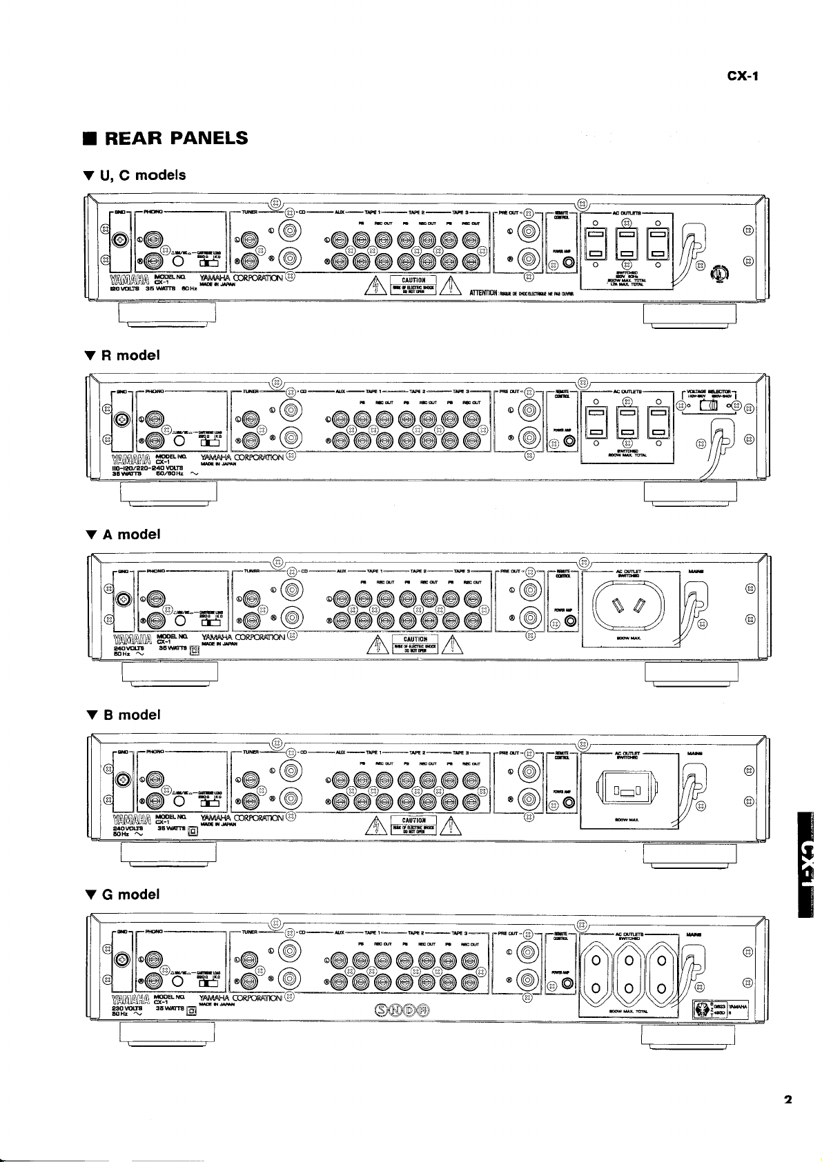
T REAR
V
U, C
ltl
l@{l'G
TJI'G
PANELS
models
r:xr|_*tE-ff=t
'9ll
[
.OlkatilH
il
yw.
T*]{-*-xtr-uE._-\,.o"-]r.**.\,1r_ffi--]
i I ii /A in zAr,r I
loll'o^ ll.c^'Y
LIF@'"6"ry1@L9-
yffi"ffi#"
-wfffuaoR'oRArnoi'u'
'@^@^@@^@^@@^l{
:e-e @: @:L:-@l@
'Ylil
(n
lilFl [--*
--l
.-
rr:lr ra I
n-,tt'rrP)
[Fi
'
ffi
aVh)
l;t
:9o
a
V,OIMI/IH,A T99EM
trsPE
36**@
YAIMAHA
CO]ruqCRAT'ION]
.@^@p
'@"@"@
-al
,{-\
nil n
il il n_n lttl
uuu
llt
\1Jy
n
rq
\9
I
il r
,R)
\9
2
Page 4
cx-1
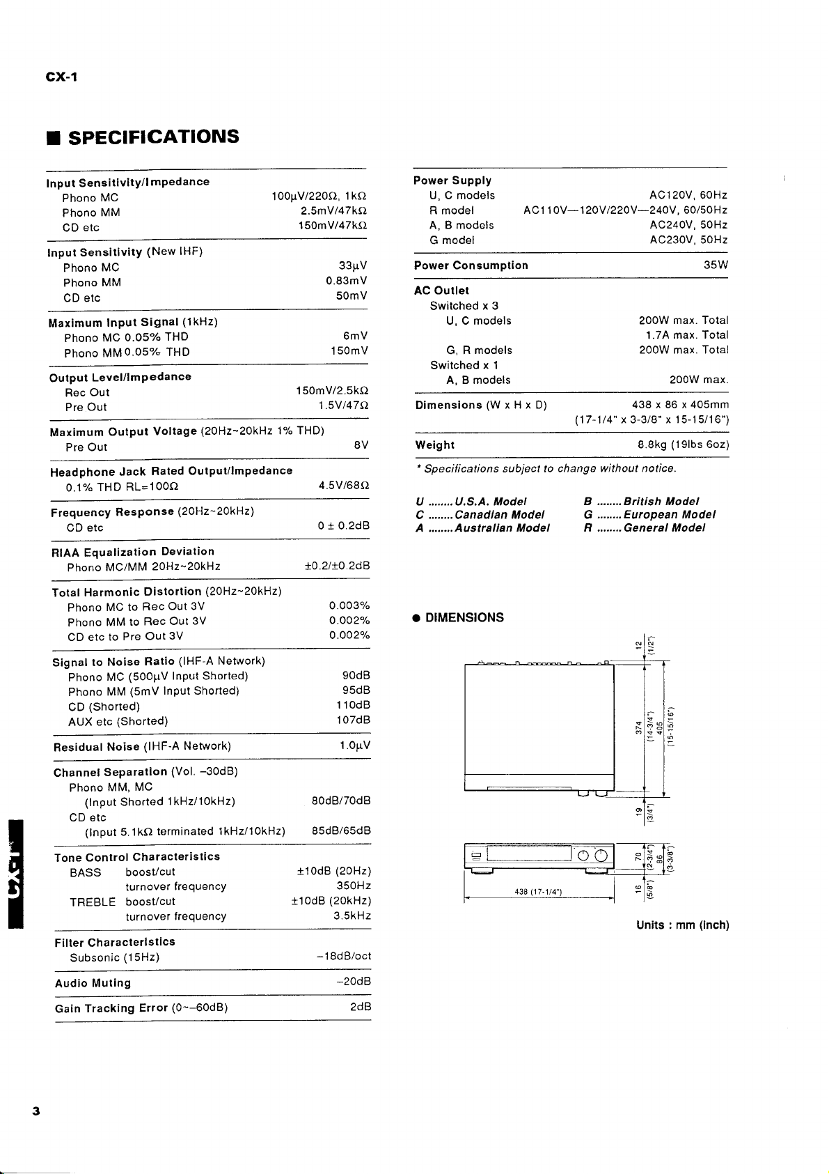
I SPECIFICATIONS
Sensitivity/l
Input
MC
Phono
MM
Phono
etc
CD
SensitivitY
lnput
MC
Phono
MM
Phono
CD etc
Maximum
MC
Phono
MM0.05%
Phono
Output
Maximum
Headphone
Level/lmPedance
Out
Rec
Out
Pre
Pre Out
THD
0.1%
Frequency
CD etc
Equatization
RIAA
MC/MM
Phono
Harmonic
Total
MC to
Phono
MM
Phono
CD etc
to
Signal
Phono
Phono
(Shorted)
CD
etc
AUX
Residual
Channel
Separation
Phono
(lnput
etc
CD
(lnput 5. 1 kC)
Input
Output
to
Noise
MC
MM
Noise
MM,
mPedance
(New IHF)
(1kHz)
Signal
THD
0.05"/o
THD
Voltage
Rated
Jack
RL=100O
ResPonse
ZOHz-2QkHz
Distortion
Rec
Rec
to
Out
Pre
Ratio
(50OPV InPut Shorted)
(5mV
(Shorted)
(lHF-A
MC
Shorted
terminated
(2OHz-Z0kHz 1% THD)
Outputilmpedance
(20H2-20kHz)
Deviation
(20H2-20kHz)
Out 3V
3V
Out
3V
(lHF-A
Network)
InPut Shorted)
Network)
-30d8)
(Vol.
1 kHz/1OkHz)
l kHz/1okHz)
100pV/220O,1ko
2.SmY/47ka
1 50mV/47kO
33pV
0.83mV
50mV
6mV
150mV
150mV/2.5kO
t47l,)
1 .5V
8V Weight
4.5V/68O
0 I 0.2d8
10.2/r0.2dB
0.003%
o.ooza"
0.002"k
90dB
v50ti
1 10dB
07dB
1
1.0pV
80dB/70d8
85dB/65d8
Supply
Power
U, C models
model
R
A, B models
model
G
Consumption
Power
Outlet
AC
Switched
U, C models
models
G, R
Switched x 1
A, B models
Dimensions(WxHxD)
'
Specifications
U ........U.5.A. Modet
........
C
Canadlan
A ........Australlan
AC1 1 0V-1 20V 1220V
x 3
subject to
Model
Model
. DIMENSIONS
AC120V,60Hz
-24OV,
AC240V, 50Hz
AC230V, 50Hz
200W
1.7A
200W max. Total
438x86x405mm
(17-1t4"
change without notice.
x 3-3/8" x 15-15/16")
8.8k9
B ........ British Model
......., European Model
G
R,,....,.General Model
60/50H2
35W
max. Total
max. Total
max.
200W
(l9lbs
6oz)
Control
Tone
BASS
TREBLE
Filler Characteristics
Subsonic
Audio
Tracking
Gain
Characteristics
boost/cut
turnover
boost/cut
turnover
(1
Muting
5Hz)
Error
frequencY
frequencY
(0--60d8)
t1odB
+10d8
-1
(20H2)
350H2
(20kHz)
3.5kHz
8dB/oct
-20d8
2dB
Units : mm
(inch)
Page 5
cx-1
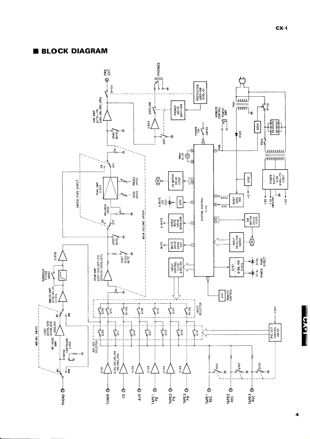
BLOGK
I
DIAGRAM
>:6
I
I
I
li'l
;
=:
_:
dl
=l
I
I
I
(
o
><l
zq
:"d
,\"-N
6=
G=
5!
sB
rl
ol
tl
zl
=i
q
u
z
-
da
ts
o
F
-=
>l
tl
ffi_
t^l
| fr:^:* |
>--+
=a
g:
J
=
| ;q:d! |
l--61
TTI-_T
l"'+ 1
I
oN;o
F
=:l
-
<
I
=Fg3
N-tr
++ol
=
lc
9g
:J-
s3
?fr
=
i;
?3*
-i_i
\'+
r
;?=
9u
=
\r-+
=z
a6
cu
ogJ
ET
-----l
,-83
FND
u9 uo uS,)
cu
<c <E <E
FtsF
=
=
T_
I
I
I
L_
;<
-
"
r^tw--+
I
EOX
uo
z<
-_.5
!s
4
Page 6
cx-t
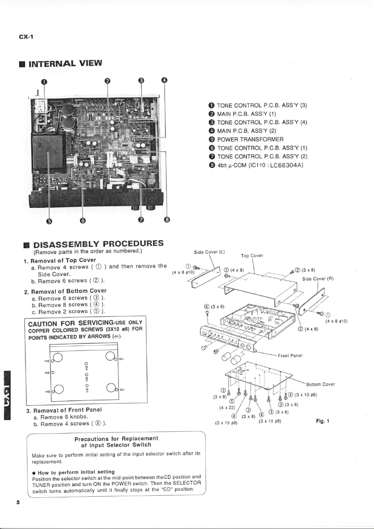
INTERNAL
I
DISASSEMBLY
T
(R€move
1. Removal
parts in
ot ToP
a. Removo
Cover.
Side
VIEW
the ord€r
Cover
screws ( O
4
b.Rsmov€6scrsws(@).
Bottom
Removal
2.
a. Remove
b. Removs
c. Remove
CAUTION
ioppen
POINIS
ol
screws
6
g
screws
screws
2
FOR
coloReo
INDICATED
SERVICING'USE
scREws
BY
PROGEDURES
numbered')
as
remove
then
and
)
covor
@).
o).
o).
oNLY
(3xr0.€) FoF
AFROWS
(F)'
lhe
n,rr9roY>
<l
Sid6
ToNE coNrRoL
O
P.c.B. Ass'Y
MA|N
O
ToNE coNTRoL
a,
P.c.B. ASS'Y
MA|N
O
PoWER
O
ToNE coNTRoL
O
ToNE coNTRoL
O
+Uiur-COt',t
@
(L)
Cov€r
TRANSFORMER
@{qxa)
P.c.B. ASS'Y
P.c.B. Ass'Y
P.c.B.
P.c.B. Ass'Y
(lC110
:
(3)
(1)
(4)
(2)
(1)
Ass'Y
(2)
1C66304A)
(4
r I
tlo)
o
1l
o
lt
n
Panal
Front
Removal
3.
a. Removo
b.Removs4screws(@).
Make
rEolacament.
a How
io"ition
tUt,tEn
switch
ol
6
to
sure
Perform
petlorm
to
the s"l"ctot
position ana
automaticalty
turns
knobs.
Precautlons
ol InPut
initial
Initlat
"witch
ON the
turn
lor
Selsclor
setting
gettlng
mid-point
at the
POWER
it tinally
until
F€Placement
Switch
input selector
ol the
betweEn
switch.
at the'CD"
stops
switch
theCD
Then the
its
alter
position-and
SELECTOR
Position
@
(3xB)
14
(3
x 10
x 22)
08)
(3 x t0
@(sxtots)
08)
Bottom
Covor
Page 7
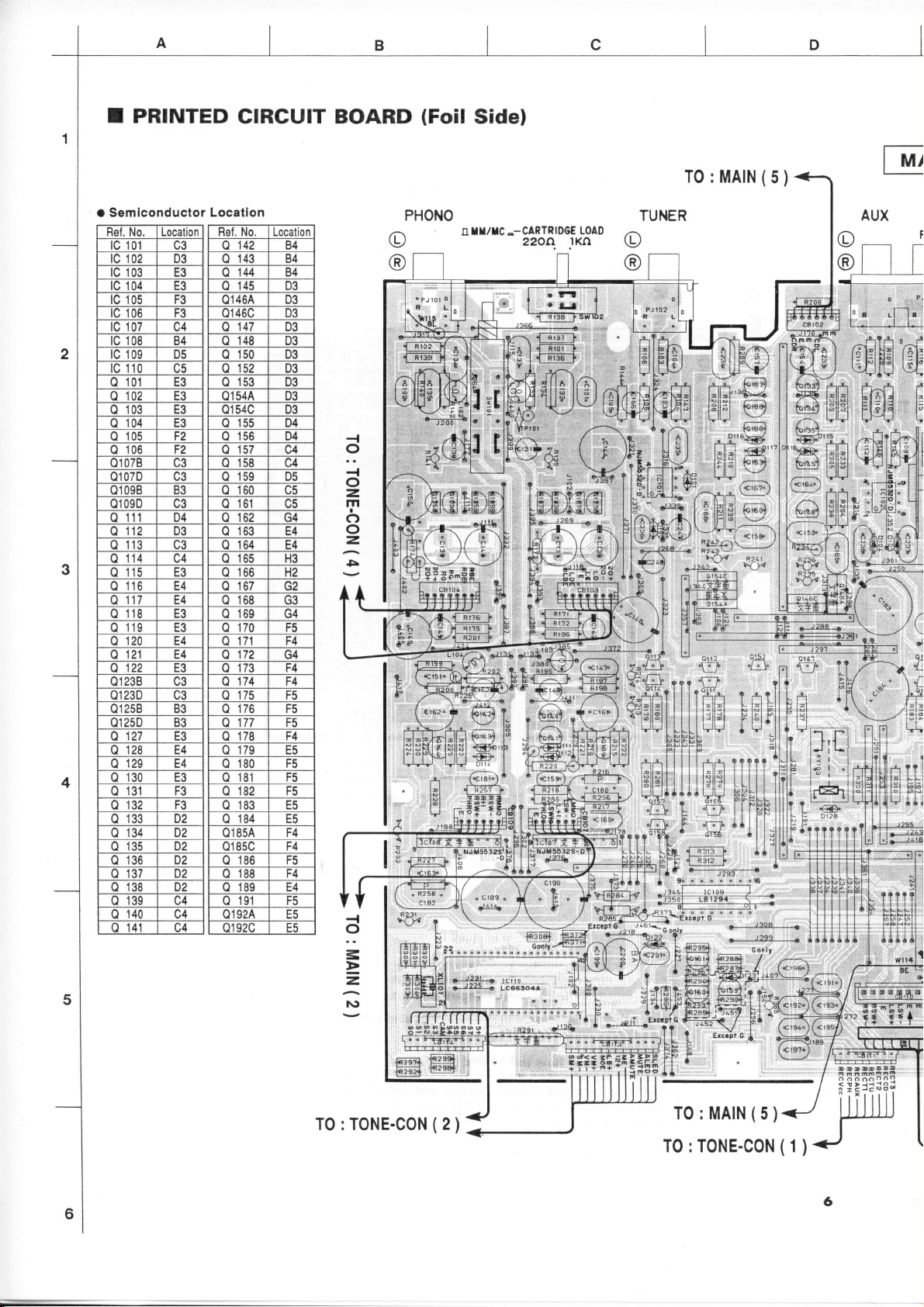
I PRINTED
CIRCUIT BOARD
(Foil
Side)
t Semiconductor Location
Localion
NO
aa
01
tc 02
D3
E3
lc
04
UO rJ
07
08
no
'10
rJ
B4
D5
t3
tc 05
l^
tc
ta
o 01
o 02
03 E3
o
04
a
05
F2
lrn
o
Q1
o1 07D
Q1098
01 090
o
(]
o l3
0
7B
'l
1 D4
14
F
na
bJ
ae
D3
UJ
15 E3
16 E4
n
17
E4
18
19 E3
20 E4
21 E4
o1238 c3
TJ
3D c3
Q1
o1258
25D
Q1
n
o 28 E4
o 30
n
o
o 33
0 34
c2
27 E3
trA
29
E3
F3
31
JZ rJ
vz
n)
o D2
JO
o
138
D2
3/ D2
NO Localion
o 44
0 D3
Q1464 D3
o1 46C D3
o 147 D3
()
148
150 D3
Q
o 152 D3
o 153 D3
54A D3
Q1
o1 54C
o 55
ab
o
59
0
60
0
61
oz u4
o
63
64
65 H3
oo
b/ 5t
68
o 69
70 F5
71 F4
u
7 G4
/J
o
(.)
75
o
77 F5
o
td
80
81
82
(,]
83
84
0185A
o1 8sc F4
o 186
o 191
14 )4
)4
924 E5
Q1
01 92C E5
B4
B4
84
D3
D3
D4
D4
NK
U3
r4
E4
H2
ua
F4
F4
F5
F(
F4
Ef,
F6
F5
ts5
EA
ff,
ai
F5
{
o
{
o
=
m
c)
o
z,
5
PHONO
II/IC._CARTRIDGE
U
.O
2200.
LOAO
.lKn
@[t
.ft
t1t
-t"l
i+
g
-|-
rild.J
qjen
a
Al{ 6*4
l"ll.l'3b4
lHil:t F;4
Lil l
r€69
fo
-?'"w
l"ll.l @"
l;'llYi 6orerd
HflV
{-G)
*
/^nlA
I I ll:llfrl a';a
I
\-,Lrlrl---1
ii
lFllBl
\_-/
^at6.r\
-/
Page 8
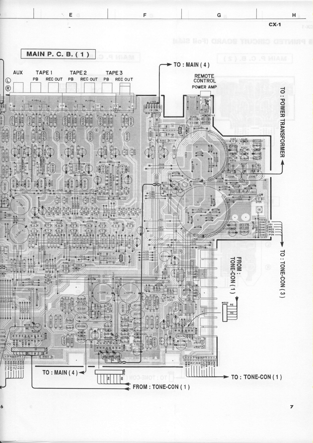
I
MATNP.C.B.(1)
G
H
cx-1
AUX
TAPE I
PB
REC
OUT
TAPE
2
PB REC OUT
dHSH
TAPE 3
PB
ffiffi
"ffi
B'ffi
REC OUT
EM
g
TO
-#e
'nv1-'
r-F1
: MAIN
REMOTE
CONTROL
POWER AMP
0
o
Jllf-
?
F0
\
\
(4
)
I
!
o
=
m
:tr
-{
r
z,
U'
-Tl
o
3
=
m
ft
?
FA
LP
AA+ /
tltil I -t
l3l
idi
l3l b'g4 \-
lBl l:ll:l
|-l
uu
T0
: MAIN
€2r$
J
-
5;31""*
(a
)
cu!'b
S$J'-
#l
FROM:TONE-CON(1)
\---l
an
=
-'
Ql iH
FH|[F|F$E'=
llt
^}/.\ -
.d)?ir:od h-t4 F i. lH---l -'2+
;S,'s{ f;'q
_<cg krsel hot6", l" lf+--.1
\--./
-l
C)r
z.o
r.n
c)
o
=
:
TO: TONE-CON
E-
----''l
poN
-----.1
"
f
i^1
v
{
o
-{
o
z,
m
c)
o
z.
(lt
(1
)
7
Page 9
cx-1
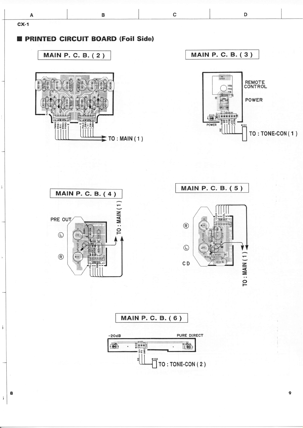
I PRINTED
MATNP.C.B.(2)
CIRGUIT
BOARD
TO
: MAIN
(Foil
Sidel
(1
)
MATNP.C.B.(3)
REMOTE
CONTROL
POWER
: TONE-CON
T0
(1
)
MATNP.C.B.(4)
PRE
o
@
=
=
o
MATNP.C.B.(6)
MATNP.C.B.(5)
@
o
CD
PURE DIRECT
z
=
o
F
Page 10
-n
5
o
=
-l
o
=
m
o
o
=
l'lcl"I-
VOLUME
at
:D
o
=
=
=
qt
a
AuX-PTUNER
rtr$EEr{ )PHol{o
TAPE 3\-/
{
o
{
o
=
m
I
CA
o
=
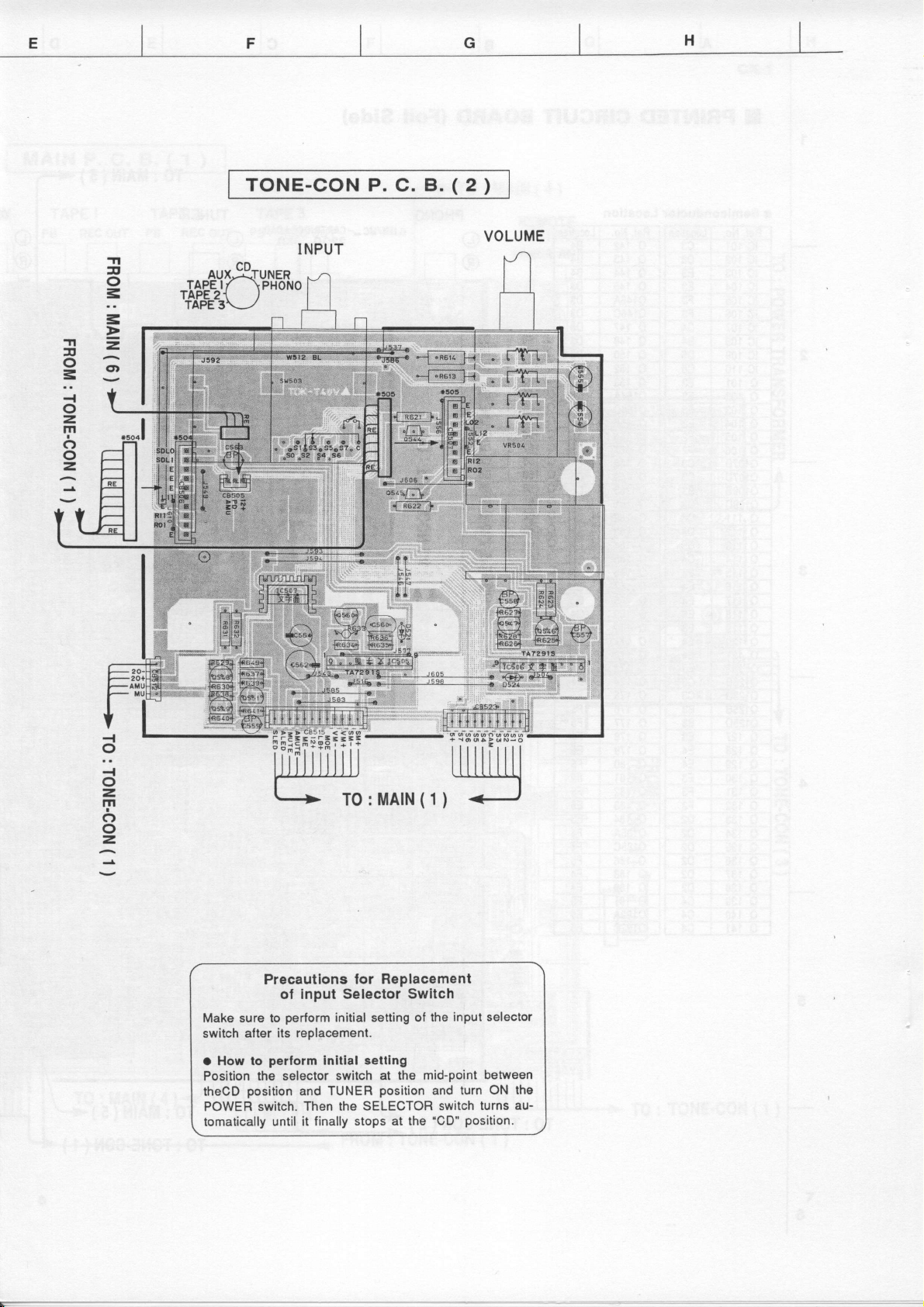
Precautlons
ol Inpul Salector
Make sure to
switch afler its
o How to
Position
theCD
POWER switch.
tomatically until
pertorrn
perlorm
the selector switch
position
TO:MAIN(1)
lor Replacement
initial setting of
replgcsment.
rettlng
Inltlal
and TUNER
Then the
it finally
SELECTOR
stops at the
Swltch
mid-point
at the
position
the input
and turn ON
switch turns
'CD'
selector
between
position.
the
au-
Page 11
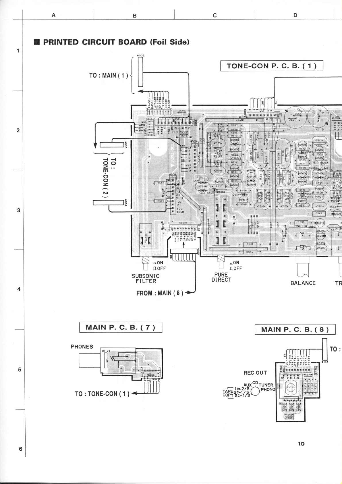
I PRINTED CIRCUIT
L---__/
oo
2,..
m
c)
o
=
l\)
BOARD
(Foil
Sidel
TONE-CON
P.
C.
B.
(
1
)
MATNP.C.B.(7)
T0 : TONE-CON
(1
)
SUBSONIC
FI
LTER
MAIN
FROM
:
(8
PURE
DIRECT
)
MATNP.C.B.(8)
to
Page 12
l*'MA'N(1)
(1
MAIN
TO:
)
lcl
dc
-Tt
T
o
=
=
=
<.)
H
cx-1
).8.(8)
T0:T0NE-CON(1)
TO :
TONE-CON
)
(7
MAIN
P.
C.
B.
(
4
)
to
tl
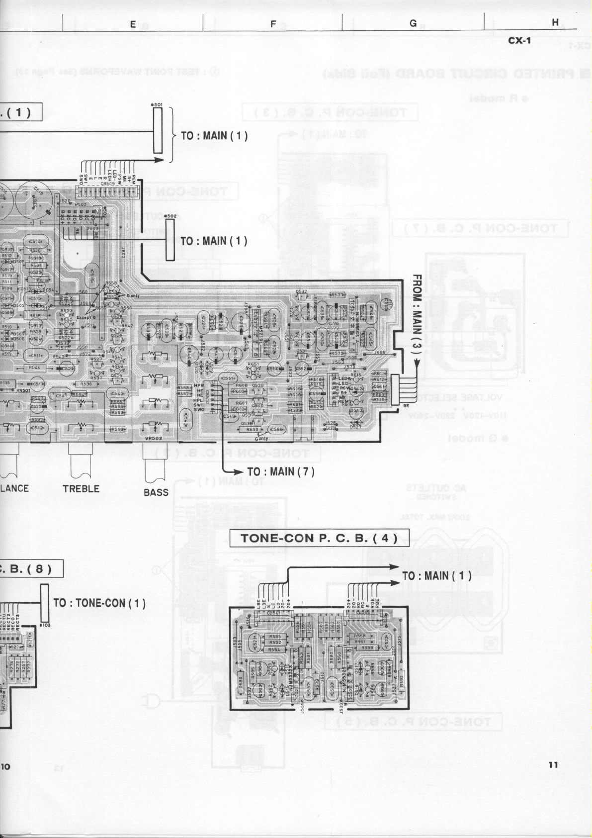
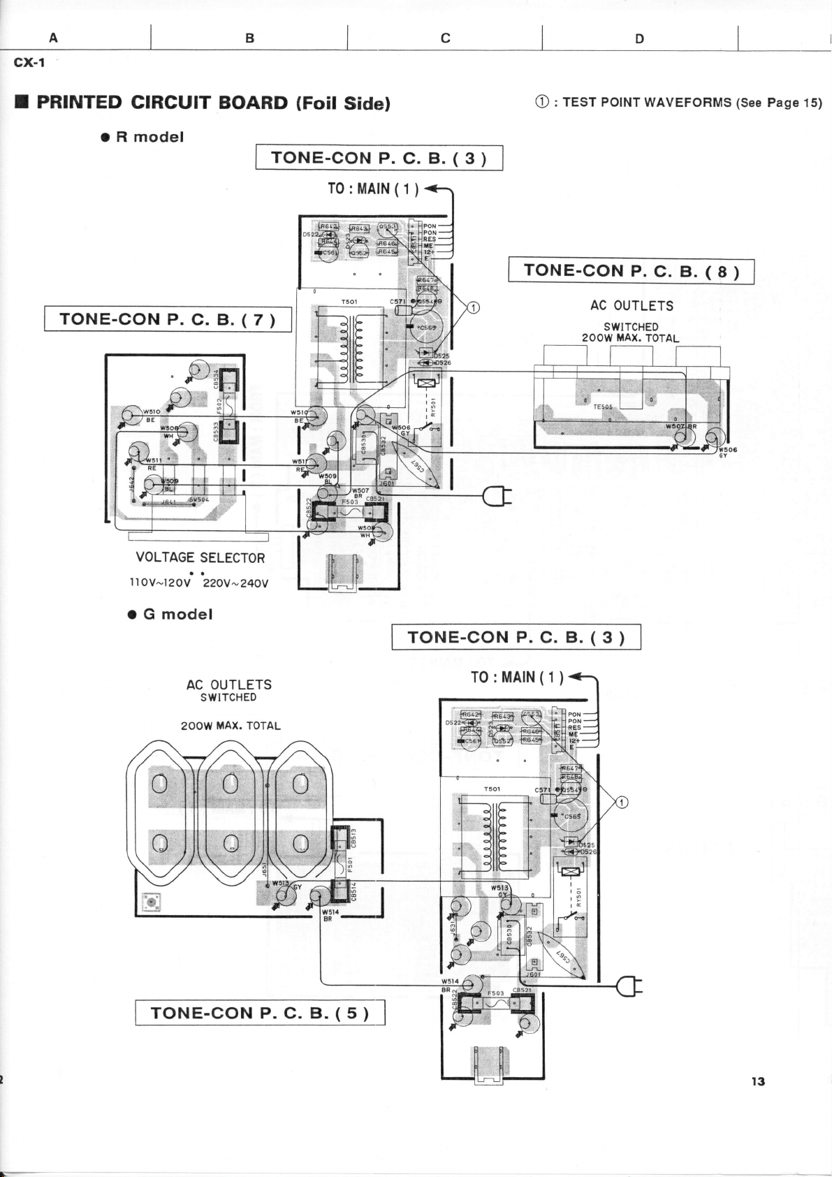
Page 13
cx-1
c
D
I
PRINTED
TONE-CON
CIRCUIT BOARD
O R model
P.
C.
B.
(Foil
TONE-CON
ffiffi
tc56! tos24
(
7
)
Sidel
P.
C.
T0:MAIN
(1
)
B.
(
3
: TEST POINT
O
WAVEFORMS
(See
Page 15)
)
TONE-CON
2OOW
P.
AC
OUTLETS
SWITCHED
MAX.
C. B.
TOTAL
(
8
)
VOLTAGE
llOv-I20V
o G model
SELECTOR
ao
AC
swtTcHE0
2OOW
22OY-24OY
OUTLETS
MAX. TOTAL
TONE-CON
T0:MAIN(1)
@B fiF.e
""'ffiq
*cs6rl b$aj
.
\-/
P.
C. B.
(
3
)
TONE-CON P. C. B. ( 5
)
l3
Page 14
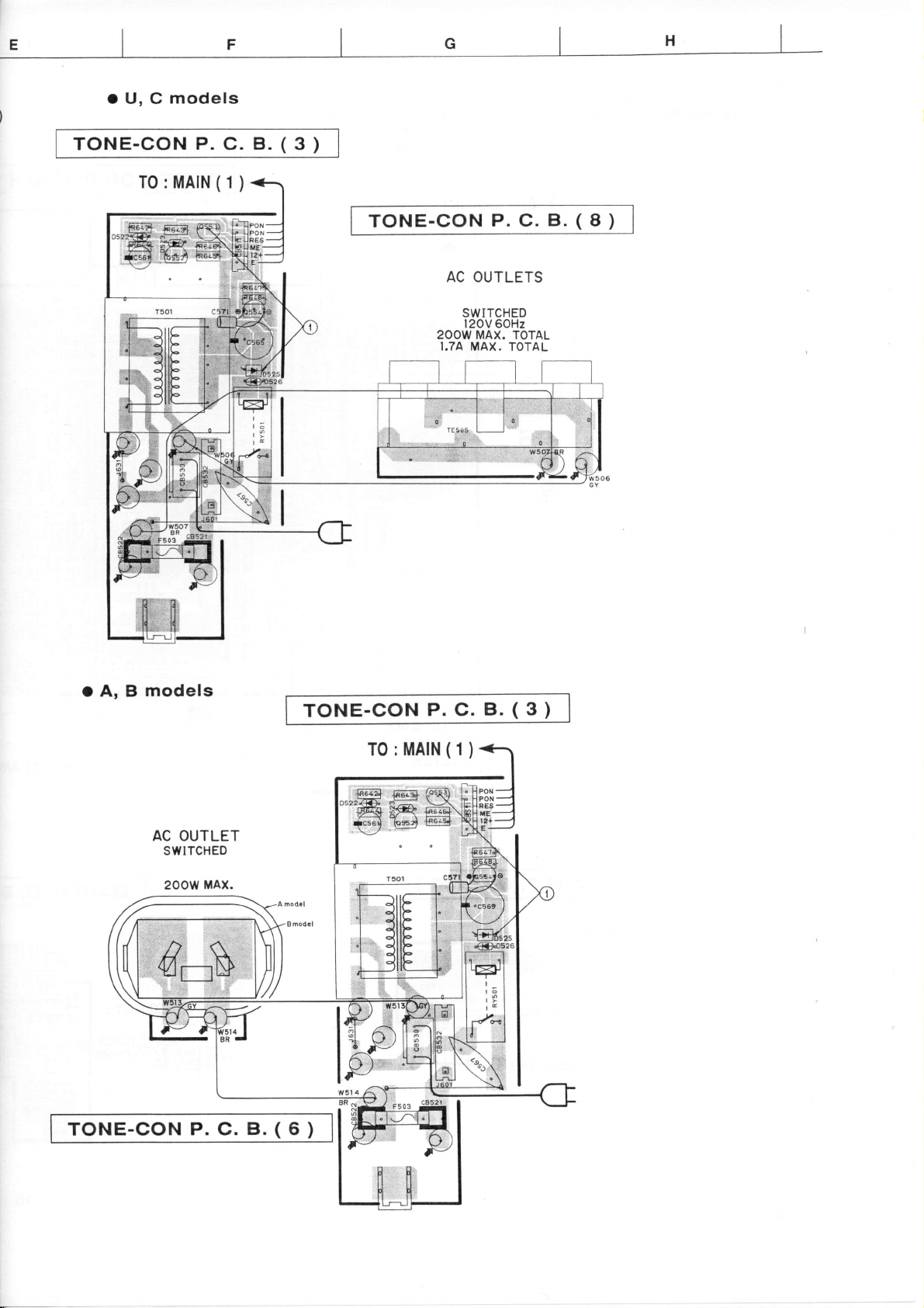
o U, C
models
TONE-CON
P. C.
B.
(
3
)
T0:MAIN
(1
)
TONE-CON
AC OUTLETS
SWITCHED
l2OV 60Hz
2OOW MAX. TOTAL
P. C.
B. ( I
)
o A, B
models
AC OUTLET
SWITCHED
200w
TONE-CON
MAx.
P. C.
B.
TONE-CON
(
6
)
P. C.
T0 :MAIN
o':-
D'IR
{e5E2,
(1
B. ( 3
)
)
Page 15

cx-1
p-GOM
I
DATA
|Cl10:1G66304A
p-GOM
4bit
PO
P0l
PV
P03
Pt0
Pll
Plz
Pt!
sro/PA
*o/P2l
ffi/m
NT0/m3
mi/P{
roT0/P3l
rcuTl/Pu
E-lPS
PO
P{
TEST
ml
PEIITAB
P€O/TRA
PO3/CMP3
POz/CVP2
POt/CMPI
POo/CMP0
P63/PrNl
puzSfi
P5t/501
P@/Sil
p:vifii?
PV
P5t
P$
Pa3
Pa2
osc2
osct
osc2
POUTO
sro
so0
sF6
INTO
iNri
INYT
sil
sol
SeK-l
PIN1,
POUTI
PORT
No.
P00
1
P01
2
P02
3
P03
4
P10
5
P11
6
P12 o
7
P13
8
sl0/P20
9
so0/P21
10
scxotpzz
11
tNT0/P23
12
nrrrtpso
t3
14 POUTO/P31
POUTl/P32
15
HOLD/P33
16
't7
P40 o
P41
18
TEST
19
VSS
20
oscl
21
NAME FUNCTION
UO
o MUTE Mute
o AMUTE Audio
o AMLED
o STBY Standby
o SM+
o SM-
VM+
VM-
o PON Main Relay ON
PWSW
REM Remote Control
PWDN Power Down Detect
T1
o T2
Mute
Audio Mute LED
LED
)
Input Selector
I
)
)up
Main Volume
I
/
)^..
Power SW
)"
) rRpe r
Function Select
I
)
GND
GND
(4MHz)
Clock
Turn Right
Iurn Left
Down
(POWER
ON/OFF)
TAPE?
No. PORT UO
22
osc2
RES
23
24 P42
NAME FUNCTION
o Clock
fttrD
Res€t Input
T3 Funclion
25 P43 N. C.
26 P50 o PH
27 P51 o
28 P52 o CD
TU
Function
29 P53/lNT2 o AUX
30 P60/St1 s0
P61/SO1
31
32
P62lSCKl
s1
s2
33 P63/PtNl S3
PC2lVREFO N. C.
34
35 PC3/VREF1 CAM Cam
36 PDO/CMPO s4
PD1/CMPl
37
S5
38 PD2/CMP2 s6
39 PD3/CMP3 s7
40 VDD +5V
41 PEO/TRA
42 PE1/TRB
MarketDetect H:G L:NotG
Model Detect
(4MHz)
Select TAPE 3
Select
Posilion Detect
H:CX-1
PHONO
TUNER
CD
AUX
I
3
il
I
L:CX-2
l4
Page 16

cx-1
I
BLOCK
IG
|C101-104
OP-AmP
Dual
|C105-108
1C501,
1G504
Dual
1C109
Drlver
502
NJM4556S-A
:
OP-Amp
-Vinl
Vcc Vo1
: L81294
Array
NJM5532D'D
:
: NJM5532SD
NJM5532S
:
-Vin2
+Vinr
VEE +Vinz
Voz Vcc
1C503 : M52191
Dual
OP-Amp
tszz_9=z=9
6t+l+r5+
1C505,506
-ONNNO
: TA7291S
Motor Driver
INPUT OUTPUT
tN2 OUTl ouT2
tNl
0 0 STOP
,|
0
1
H
0
1 L H
I L BRAKE
MODE
cwccw
ccwcw
I
Point
V :SV/div
H :
1
t5
WAVEFORM
ICHZ
: Cathode
: Collector
V:2Vidiv
DC
O IcHt
lsec/div
probe
: 1
(CHl)
OF
of D525
of Q553J
range
TEST
(CH2)
POINT
)
5U
Wirh the POWER
switch turned
connect the oower
cord to the
2U
(This waveform
power
the
SF
ON,
AC oudet.
switch
PLI
is not
ON and
Disconnect the
power
cord
outlet.
the AC
available
by
OFF.)
from
pushing
Page 17

I
SCHEMATIC
DIAGRAM
(MAIN}
AMP
A
BU
F'F
r
ER
I
I
MC HEAD
AMP
I
I
I
Page 18

Page 19

I
G
H
5Y5TfM
Page 20

ll
3
Yfut"
qq
O d8
AMP
K
M
N
cx-1
PIN
CONNECTION
TRANSISTORS,
2SA970
2SAr015
238737
2SCr81s
2SC22.r0
2SD786
2SD1915
DTA124ES
DIODES
(GR,
8L)
(Y)
(O,
R,
(Y)
(GR,
(O,
R,
(F)
S.
DIAGRAM
AND ICS.
S)
BL)
S)
T
^.
OF
'ild
'illiL"
Hilifii:
258949
2SD175
38elfl8vl
1ss133
M4185
MTZ'6.28
MTZ)8.2C
MTZ,I6.8C
DzS8A20
L81294
I
___J
I
I
(P,
(P,
O,
"4
R)
O, R)
"a:
d<
{*>
.RCL
&c,n, r
t
Clro' ltl ?20F/rN rllF/t00
le
r3
t1 Rt!. ?0? 420 z,a<
,a5e o
,J{5t'
!6
rt
RE'I
t7 F2!9. eE , ag$ 294 x to(
r8 tn crBr6lYl
tt !o
rul Dta! x rsttsl
ntTt
rll
rla wtr e.a
ll J{6'
rnt*cnangaebl0 Paa'te at lLtf,rfactrlro-gtago
tl
e PaFt, P.^tr
ul0t
T
ta'or
x
Arot'lYl
toc(
I
gFfllttll
eP167U
Page 21

Fltro2
*fl{
FYtGt
cYtzHlt-l
rntanchangsaola Paftr at lgrutacttrr-stago
ll ut0t
lFlr.!otr
8Pil!7u
POWER
SUPPLY
l_._r
Pa? P t7
@E=
rorc0rlrl roicc(nlSt
All voltage
measured
are
Components having
must
originally
replaced with
be
installed.
Schematic diagram
with a l0tvlWV
special characteristics
parts
having
specifications equal to those
is
subject
to
change
without notice.
DC electric
marked A anA
are
volt
meter.
IC
Page 22

l:
r! flf,rol
""
#ffi1
**
€1f1
=-F191
l1u:
ld I l: I
tE
l"i
I rto:t
I
t
gj*^
Page 23

B
188
corrlYl
pr$
'2.9
I
nArNrtl
I
r
I
I
I
sFV
nl
Pglggc]
il
llEg/i r
lLlf;
-J!u.IE _ _ J
IMArN{g)l
I
I
fi4ANiTT I
___t
I
r
I
I
I
I
-t
I
I
I
I
tt03
PtotPA
|----...-..-1
ffi
rtrrtttttl
TDGC|trltl
rrr
lETl
ro€0||ltl
l.
PI?
-
6-]
Page 24

I
l_
ffi"rf,
P.r!06
|;t-
Irlj
t-lz
o;[
E
:
REXAP( PAN TS
llo I
AnB 0x EFS I r0F
iIEIAL OXIDE FILT NESISTON
TFT nFs Tnp
IIETAL PLATF FEgISTOF
pn00F
IPF
CEXEIIl IIOLNEO FESISTOR
CHIP RESISION
nFrlnts PAITI NI IIF
t0 illPK cTnoLYTIC CtpleIr0n
s
lERl[1C ClFlCIr0F
AXIIL
Pot rFEIFt FIt I Clplclron
l,tl
SEXI CONDUCIIf F CFNAllT[ CIPICTION
t-.ltFdN Fil lr EFsrsr0
E1{I IARIABLE RESISTl}F
IIIIALUI{ CIPACITOR
LEAD CERAHIC CAPACITOP
9LYSTYREI{E FILII CIPTCITOR
ca cAprc IT0P
YPEOPYLEIIE FILH CAPACIION
ill
s
{l
Page 25

cx-1
r
SCHEMATIC
DIAGRAM
(TONE-CON}
I
MC
HEAD
O:r
AMP
I
l_
zOdB
AMP
I
_J
am3
r!r03
_
Page 26

ST POINT
WAVEFORMS
(See
Page
15)
ffi
r^ttro
...-C-l
--{
-J
I
|
MOTOR
A
DRIVE
MUTE
DR IVE
A!0r51
-
0316
20.0
Yl
AUDTO
MUTE
DR IVE
^'o'frf?,
_,OO'
Page 27

VIUTE
)RIVE
Ar0ttlv
-?o.o
AUDIO
MUTE
DR IVE
^ro'i"ri
-.OO'
MOTOR
AA
DRIVE
Page 28

t/6t I
I
Uut
I
r=
51ST0R
I
(R)
SELECTOR POSITION
z
tr
z
q
33
3za c56€
s5
36
J7
s0
99
310
stl
El2
313
8ta
ri5 FIiO2
st6
Q'
q{n
rol€coN(il]
I
l!9to_
]Yryql
-aq{-
IIP_E_1_
IlP_11
TAPE
tl
e2
s50
ntot xtit366
lEltot
Sruo,l
c8533,534
!84t,642
"E:tl
.E!l
cEEl t3.
F!01
F503
ffi,658
.J662.6:i:t
DATA
s0 s1
3
gN
r:
u,c
x
vco7E{O
x
x
x
x
5t4 X
x x
x T.l00tA250V
2Aa50V
x x
A
S160,l
la
(INPUT)
s2
s3 s4 s5
12
10
9 I
I
I'
I:
'I.
t_I
EXTENT
R
A.0
X
x
x
xt{357
v@744o
WlaEEO
vP?o850
x
x
x
a^250v T,f00nA250Y
xx366
x
x I
x x
o
x
o
x
x
x
x
I
x
1-
s6
s7
7
o
0.0,{7
1.7
IiGt69
I
x
o
o
vF20510
Te.
S asv
x
I,l{t0na250v
x
o
PIN
CONNECTION
TRANSISTORS,
2541015
2SBs60
2SCr815
2SC2240
2SAB8
2SA1er7
2SC47e3
DIODES
(Y)
(E,
R
(n
(GR,
8L)
(E,
F)
(O,
Y)
(O,
Y)
DIAGRAM
AND
2sK38effi
NJM78Ml2FA
r
I
ii:irf
2rCorEa
3!Ot
ThrT
1ss133
1sR139-100
MTZJ4.38
MTA4.7A
MTAs.1A
MTZJ6.2A
MTZ'6.2C
M5219L
nntx.3^ffi
TA7291S
OF
ICS.
TtlR
rcIr0H
Page 29

POWER
S U PFLY
A
tls
rSFUtS-l00r6e
SI.,'B
'
All voltage
'
Components
must
be replaced
originally
'
Schematic
are measured
having
special
diagram
with
is
installed.
with
characteristics
parts
having
subject
a l1ttlcvv
specifications
to change
DC
electric vort
are
without
marked
equal
notice.
meter.
and
A
to those
Page 30

PHONES
DR IVE
RESET
I
l-ruNrcoNGil I
l_-.--J
I
-_
Page 31

TONE
CONTROL
Fi-
tt--
I lI l-
tl
t-
L:f-
rArNr3r
Pt6
fz:Fl
d,
_^ I
PHONE
=b-546
otgrsrlsrrt
|
AMP
PHONES
DRIVE
cESrl
r@
r'rAtNt
Pr6
E
<qq
-<epi
-<Jol
t)
<<Jol
<qol
<sol
1
T
I
Page 32

I
I
zOdB
AMP
AU
DIO
MUTE
L
Page 33

cx-1
REMOTE
SCHEMATIC
I
CONTROL
DIAGRAM
r/oo3 Krloo
t/ooz
Kt/o1
t/oo1 Kt/oz
l/ooo Krlo3
Kt/o4
s-rN
s-oti,T Ktlos
REM KIIO6
Kt/o7
voo
osc-ouT
OSC-IN
vss
AC KI3
Kro
Kt 1
Klz
TRANSMITTER
POYE
OOC
5.'boLa
5^"55c
otFl
OCf
<
OOC
ME
C]C)C
c-)
YAMAHA
ICrcTE
coxllo(
ta^tsrr
cclM
?tIY
ITOP
llc
IUTING
Yolu€
C
6
0ll
F
5T
EC
fTlP€
Kr.
C
i!i€i
C
O
' PE
O
IAPE 2
O
O
Key
CUSTAOM
(HEX)
No.
10
1
!'
11 7A
12
17
18
19
20
25 7A 0c
26 7A OD
32
7A
I
7A 01 << (TAPE)
2
7A 02
3
4 7A 03
7A 40
5
7A 04
I
7A 05
7A 07
7A 08
7A 09
7A OA
7A OB
7A 4F
33 7A
34 7A 11
35 7A
41 7A
42 7A
43 7A
44 7A
45
49 7A 18
50 7A
51 7A
52
57 7A
7A
7A
60 7A
DATA
(HEx)
00
06
10
12
14
15
16
't7
54
19
1A
1B
1C
1F
FUNCTION
(TAPE)
PLAY
>>
(TAPE)
(TAPE)
STOP
(TAPE)
DIR B
REC/PAUSE
REC MUTE
DECK A/B
DIR A
PLAY
PAUSE/STOP
ra
SKIP
r<< (CD)
sKtP
>r
SERCH
<<
sERCH
Drsc sKrP
PRESET +
PRESETNBICIDIE
PHONO
CD
TUNER
AUX
TAPE 3
TAPE 1
TAPE 2
VOLUME +
VOLUME
MUTING
POWER
(INPUT)
(INPUT)
(INPUT)
(INPUT)
(INPUT)
(INPUT)
(INPUT)
-
(TAPE)
(TAPE)
(TAPE)
(TAPE)
(CO)
(CD)
(CD)
(CD)
(CD)
(cD)
(TUNER)
(TUNER)
fiUNER)
I
I
ii
I
I8
Page 34

cx-1
PARTS
LIST
I ELECTRICAL
PARTS
r WARNING
Components having
replaced with
a
Carbon resislors
List. For
the
parts
parts
special characleristics
having
specifications
(1/6W
'll4w)
or
No.
ol the carbon resistors, refer to last
are not included in the ELECTRICAL
are
equal to those originally installed.
marked
and must
A
page.
be
PARTS
ABBREVIATIONS
C.A.EL,CHP
c.cE
C.CE.ARRAY
c.cE.cHP
C.CE.ML
C.CE.M.CHP
C,CE.SAFTY
C.CE.TUBLR
c.cE.sMl
C.EL
c.MrcA
C.ML.FLM
C.MP
C.MYLAR
C.MYLAR.ML
C.PAPER
C.PLS
C.POL
C.POLY
C.PP
C.TNTL
C.TNTL.CHP
C.TRIM
CN
CN.BS.PIN
CN.CANNON
CN.DIN
CN.FLAT
CN.POST
COIL.MX.AM
COIL.AT.FM
COIL.DT.FM
COIL.MX.FM
COIL.OUTPT
DIOD.ARRAY
DIODE,BRG
DIODE.CHP
DIODE.VAR
0toD.z.cHP
DIODE.ZENR
DSCR.CE
FER.BEAD
FER.CORE
FET,CHP
FL.DSPLY
FLTR.CE
FLTR,COMB
FLTR.LC,RF
GND.MTL
GND.TERM
HOLDER.FUS
IC.PRTCT
JUMPER.CN
JUMPER.TST
L.DTCT
IN THIS LIST
CHIP
CERAMIC CAP
CERAMIC CAP AFIRAY
CHIP CERAMIC CAP
MULTILAYER CERAMIC CAP
CHIP
RECOGNIZED
CERAMIC TUBULAR CAP
SEMI CONDUCTIVE CERAMIC
ELECTROLYTIC CAP
MICA CAP
MULTILAYER
METALLIZED PAPER CAP
MYLAR FILM CAP
MULTILAYER MYLAR FILM
PAPER CAPACITOR
POLYSTYRENE
POLYESTER FILM CAP
POLYETHYLENE FILM CAP
POLYPROPYLENE FILM CAP
TANTALUM CAP
CHIP
TRIMMER CAP
CONNECTOR
CONNECTOR. BASE PIN
CONNECTOR, CANNON
CONNECTOR, DIN
CONNECTOR. FLAT CABLE
CONNECTOR,
COIL,
COIL,
COIL,
COIL,
OUTPUT COIL
DIODE ARRAY
DIODE
CHIP DIODE
VARACTOR DIODE
CHIP ZENER DIODE
ZENER DIODE
CERAMIC
FERRITE BEADS
FERRITE CORE
CHIP
FLUORESCENT DISPLAY
CERAMIC
COMB
LC FILTER .EMI
GROUND
GROUND TERMINAL
FUSE
PROTECTOR
IC
JUMPER CONNECTOR
JUMPER,
LIGHT DETECTING MODULE
ARE
ALUMI.
MULTILAYER
TANTALUM
FET
HOLDER
ELECTROLYTIC
CERAMIC CAP
CERAMIC CAP
FILM
CAP
FILM
CAP
AM MIX
FM ANTENNA
FM
FM MIX
FILTER MODULE
BASE POST
DETECT
BRIDGE
DISCRIMINATOR
FILTER
PLATE
TEST POINT
CAP
AS
FOLLOWS
CAP
CAP
CAP
L.EMIT
LED.DSPLY
LED.INFRD
MODUL.RF
PHOT.CPL
PHOT.INTR
PHOT.RFLCT
PIN.TEST
PLST.RIVET
R.ARRAY
R.CAR
R,CAR.CHP
R.CAR.FP
B,FUS
R.MTL,CHP
R.MTL.FLM
R.MTL.OXD
R.MTL.PLAT
RSNB,CE
RSNR.CRYS
R.TW.CEM
R.WW
SCR.BND.HD
SCR.BW.HD
SCR.CUP
SCR.TERM
SCR.TR
SUPRT.PCB
SURG.PRTCT
SW.TACT
SW.LEAF
SW,LEVER
sw.MtcRo
SW.PUSH
SW.RT.ENC
SW.RT.MTB
SW.RT
SW.StIDE
TERM.SP
TERM.WRAP
THRMST.CHP
TR.CHP
TR.DGT
TR.DGT.CHP
TRANS
TRANS.PULS
TRANS.PWR
TUNER.AM
TUNER.FM
TUNER.PK
VR
VR.MTR
VR,SW
VR.SLIDE
VR.TRIM
LIGHT EMITTING MODULE
LED DISPLAY
LED, INFRARED
MODULATOR, RF
PHOTO
PHOTO INTERRUPTEH
PHOTO REFLECTOR
PIN. TEST POINT
PLASTIC RIVET
RESISTOR ARRAY
CARBON RESISTOR
CHIP RESISTOR
FLAME PROOF
FUSABLE
CHIP METAL FILM RESISTOR
METAL FILM RESISTOR
METAL OXIDE FILM RESISTOR
METAL PLATE RESISTOR
CERAMIC RESONATOR
CRYSTAL
TWIN CEMENT FIXED
WIRE WOUND RESISTOR
BIND HEAD B.TITE
BW HEAD TAPPING
CUP TITE SCREW
SCREW TERMINAL
SCREW, TRANSISTOR
SUPPORT,
SURGE PROTECTOR
TACT
LEAF SWITCH
LEVER
MICRO SWITCH
PUSH SWITCH
ROTARY
ROTARY
ROTARY
SLIDE SWITCH
SPEAKER
WRAPPING
CHIP THERMISTOR
CHIP TRANSISTOR
DIGITAL TRANSISTOR
CHIP DIGITAL TRANSISTOR
TRANSFORMER
PULSE
POWER TRANSFORMER
TUNER PACK,
TUNER PACK,
FRONT.END
ROTARY POTENTIOMETER
POTENTIOMETER WITH MOTOR
POTENTIOMETER WITH
SLIDE POTENTIOMETER
TRIMMER POTENTIOMETER
COUPLER
CARBON RESISTOR
RESISTOR
RESONATOR
RESISTOR
SCREW
SCREW
P.C,B.
SWITCH
SWITCH
ENCOOER
SWITCH WITH MOTOR
SWITCH
TERMINAL
TERMINAL
TRANSFORMER
ASS'y
AM
FM
TUNER PACK
ROTARY SW
t9
Note)
Those
parts
marked with
"#"
are not included
in
the
P.C.B.
ass'v
Page 35

cx-1
Ref.
cBi02
cB103
cB104
cB10i
cBl09
c8110
c8115
cB1i6
cBl18
cBL19
cl01
cr\2
c103
c104
c105
c106
c107
c10B
c109
c110
c111
clI2
c113
ci14
c115
c116
c117
c118
c119
c120
CT2T
vLzz
cr23
''
UI4
c125
vLzo
cl2'7
cr28
cI29
c130
c131
cr32
c133
c134
c135
UlJO
c137
c138
c139
c140
c141
*
Parts
New
N0.
PART
vi3?7500
\D994800
v8994800
vi37?600
vi37i600
vr845400
vr845000
vr845200
rA002320
vi37i600
vQ463000
vQ463000
vc290900
vQ462600
vQA62500
vG290900
vK534000
vt(534000
vc290900
vQ462600
vQA62500
vc290900
vG290900
vQ4 62600
vQ462600
vc290900
vQ462600
vQ462600
vc290900
vQ462500
vQ462600
vc290900
vQA62600
vQ462600
vc290900
vQ462600
vQ462500
JiG290900
vQ462600
vQ462600
VG2BB9OO
uT453470
vP755700
vP755700
uT453470
vc288900
vc286600
vG286600
vG286600
vc286600
vG291000
CN.BS.P]N
CN
CN
Description
MQ
M0
CN.BS.PIN
CN.BS.PIN
CN
CN.BS.PIN
CN
TER},I.WRAP
CN.BS.PIN
C.MYLAR
C.MYLAR
c.Er,
C.MYJ,AR
C.MYLAR
c. Er
C.PP
EL
C.
C.MYLAR
C.MYLAR
EL
C.
EL
C.
C.MYIAR
C.MYLAR
EL
C.
C.MYLAR
C.MYLAR
Et
c.
C.MYLAR
C.MYLAR
Et
c.
C.MYLAR
C.MYLAR
c.EL
C.MYLAR
C.MYLAR
c.Et
C.MYLAR
C.MYIAR
Et
c.
PP
C.
C.PP
C.PP
EL
C.
C. EL
c. Er
c. Er
Et
c.
EL
C.
MQ
MQ
MQ
XH
XH
XH
i-TYPE
3P
MQ
0.047uF
0.047uF
10uF 50V
220pF
220p8
10uF 50V
220p8
220pF
10uF 50V
220pt 50V
220pF 50V
10ui' 50V
10uF
220p8
220pF
10uF
220p8
220p8
10uF
220p8
220p8
10uF
220p8 50V
220p8
L0uF
220pF 50v
220pF
10uF
220p8
220p8
100uF
4700pF
0.018uF
0.01BuF
4700pF
100uF
i000uF 6.3V
1000uF
1000uF 6.3V
1000uF
22uE
1OP TE
50V
50V
50V
50V
200v
200V
50V
50V
50V
50V
50V
50V
50V
50V
50V
50V
50V
50V
50V
50V
50V
50V
25v
100V
100V
i00V
100V
25V
6.3V
6.3V
50V
MAIN
5P TE
7P
7P
TE
6P
6P TE
6P TE
8P TE
P=7.5
6P TE
P. C. B.
Schm
Ref. PART
cr42
c143
i1 AA
c145
c145
cl41
c14i
c14B
c14
c150
c151
c151
c152
I tt{
t\1
x
*
c157
ci5B
clse
I
c160
I
c161
I
ci62
I
c163
I
c164
I
c16s
I
ci67
I
c16B
I
ln16q
c170
I
lct?1
t---
lcrl2
ln1??
Iw!
lr-ttt
t--''
c175
I
c176
I
c177
I
c1?8
I
C179
I
I r'r nn
ciBl
I
c1B2
I
c1B3
I
c184
I
lclRq
I r'r nr
1.1 n?
c1B8
I
lr,1 nq
c1e0
I
c1e1
I
lcrez
c1e3
I
I c194
*
New
vc291000
vc2e0e00
w2484001
vc2e0e00
vc290e00
ur4s2220
uT4s2330
vi'248400
vr'248400
9
vr248400
vr452220
uT452330
vc2e0e00
vr884000
C.
A
vQ561900
v0561900
vr884000
vi717200
uA653330
vc286600
vc286600
uA653330
vQ282400
vi$34100
vK534100
v0282400
vc290900
vQ463100
v0463200
vQ463200
vQ463000
J
vi?16900
vi?16900
vQ463000
vQ463100
v0463200
vQ463200
vc290900
vQ237i00
vi717200
I
vQzlltoo
I
I vF817200
lwauzoo
vc290900
I
uT4s2100
I
uT4s2100
I
vG290900
I
\rf817200
|
vr817200
I
uA6ss100
I
uA6ss100
I
uA6s5100
I
I uA655100
Parts
N0.
C.EL
I
C. EL
|
c.Et
C.EI
|
C.
|
C.PP
|
C. PP
|
C.EL
I
C.
|
c.Et
|
NDD
|
C.PP
|
C.
I
C.
c.
c. EL
C.PP
C.MYLAR
C.MYIAR
A ElT
V.U!
lc.EL
I C.MYLAR
I
c.PP
I
lc
t"'"
lu.rr
lc.PP
c.Et
I
c.MYLAR
I
lc.MYrAR
C.MYLAR
I
c.M/LAR
I
lc.M/LAR
c.MYLAR
I
c.MYLAR
I
c.MYLAR
I
c.MYLAR
I
c.MYLAR
I
c.Et
I
l\,.rr
c.MYLAR
I
c.PP
I
I'FT
t"'""
\-.rr!
I
lc.Et
lc.PP
Inpp
lc.EL
t^-,
u.
I
c.EL
I
c.MYLAR
I
lc.MYrAR
C.MYLAR
I
C.MY],AR
I
Description
EI,
EL
EL
PP
Et
pp
EIr
22uE
10uF
470uF
10uF
10uF
220p8 100V(UCRAB)
330pF
470uF
470uF
4?0uF
220p8 100V(UCRAB)
330p8
10uF
3300pF
10uF
10uF
3300pF
0.027uF
3300pF
1000uF
1000uF
3300pF
spF
I
0.01ur
|
0.01uF
|
spr
I
10uF
|
o.alur
I
0.68ur
|
| 0.68uF
o.otiur
I
0.015uF
I
| ^ ^--
u.ul)ur
I
0.047ur
|
0.4iur
|
0.68uF
|
0.6BuF
|
10uF
|
0.luF
|
0.027uF
|
0.1ur
|
2200uF
|
2200uF
|
10uF
|
100pF
|
100pF
|
10uF
|
2200uF
|
2200uF
|
0.1uF
|
0.1ur
|
0.1ur
|
| 0.1uF
50V
50V
25V
50V
50V
100v(G)
25V
25V
25V
100v(G)
50V
100v
25V
25V
100V
50V
50V
6.3V
6.3V
50V
630v
100V
100V
630v
50V
sov
50v
50V
sov
50V
JUV
50v
50v
50v
50v
50v
100v
sOV
100V
25v
25v
50V
100v
100v
50v
25v
25v
50v
50v
50v
50V
20
Page 36

cx-1
Schm
Ref.
c195
c196
c1.91
c198
c199
c200
c20l
c202
nrn?
c204
nrnq
LZUO
c201
c208
c209
c210
Fa1 1
L!
VL
c2l2
c213
na1 A
LA
VL
c215
IC2r6
I cct"t
c218
I
c21e
I
1c220
1c221.
1c222
|lc223
1c224
lc22s
1c226
1c221
lc22B
lc22e
c230
I
c231
I
c232
I
t^^^^
ulrr
I
1c234
lnot<
v4Jv
I
I ot71
'
lw.J
c238
I
I n?10
lv.JJ
I c)ai
t;;;;
t"''-
l|c242
1c243
t'-"
c24s
I
''c246
I c241
*
New Parts
N0.
PART
uA65s100
uA655100
uA655100
vc290900
uA655100
vF992600
uA555100
vc290900
vc291000
vG290900
vc290900
vE019900
vQ468100
vF817200
\rF'81720
vQ468100
v8019900
vc291100
vG290600
vNo11900
v8020300
\
1011900
vr883B00
vQ282400
vQ282400
vr8B3B00
vQ39s100
vQ39s100
vK534100
v1(534100
vK534400
vK534400
vQ562000
vQ562000
uG444100
vr8B3500
vr883500
vQ453000
vr972900
vr972900
vQ645600
vQ64s600
vQ64s600
v0645600
vQ645600
vQ645600
vQ645600
vQ645600
vQ645600
vQ645600
vi?15500
vi715500
vc290500
C.MYLAR
l
C.MYIAR
C.MYLAR
c.
C.MYLAR
c. Et
C.MYLAR
c.Et
c. Et
c.Et
c. Et
c. Et
C.MYLAR
c.Et
0
c.
C.MYLAR
c. Et
C. EL
c.
C.
c.
c. Er
NDD
C.PP
C. PP
npD
C. Et
c. Et
C. PP
app
C.
/'
c. Er
c.
c cF.
aDp
C. PP
C.MYIAR
C. PP
C.
C.MYLAR
C.MYTAR
C.MYLAR
C.MYLAR
C.MYLAR
C.MYIAR
C.MYLAR
C.MYLAR
C.MYIAR
C.MYLAR
C.MYIAR
C.MYTAR
C. EI
DescriPt.ion
Et
Et
Et
EI
Et
PP
pp
Et
PP
MAIN
0.1uF
0.1uF
0.1uF
10uF
0.1uF 50V
4700uF 5.5V
0.1uF 50V
10uF
22uE 50V
10uF 50V
10uF
2.2u8 50V
560pF
2200uE
2200uF
560pF 50V
2.2u8 50V
33uF 50V
2.2uF
100uF
22uE
100uF 35V
2200pF
5pF
5pr
2200pr 100V
4700uF 35V
4700uF 35V
0.01uF 100V
0.01uF
0.04?uF
0.047uF
47uF
47uF 25V
0.01uF 50V
1500pF
1500pF
0.047uF
330pF
330pF
100pr 50V
100pF 50V
100pF 50V
100pF
100pF 50V
100pF 50V
100pF 50V
100pF 50V
100pF
100pF 50V
1000pF
1000pF 50V
Lut' 50V
50V
50V
50V
50V
50V
50V
50V
25V
25V
50V
35V
50V
100V
630v
630V
100V
100V
100V
25V
100V
100V
50V
200V
200V
50V
50V
50V
P. C.
B.
Schm
Ref. PART N0. Description
|
I
|
|
c252 |
1
I
D110
D111
D112
D113
D114
D115
D116
D117
D118
Di19
D120
D121
D1.22
D123
DI24
u rt3
ULZO
D12'7
D128
DL29
D130
D131
DT32
UIJJ
D134
D135
D136
Di37
Di38
D139
D140
rc101
IC1O2
rc103
rc104
rc105
rc106
New Parts
vc290500
vc290500
vc290500
vc290500
vc290500
vc290500
vG290500
iFo04600
iFo04600
iFo04600
iFO04500
iFo04600
iFO04600
iro04600
iFo04600
iro04600
iFo04600
iFo04600
iFo04600
iFo04600
iFo04600
iFO04600
iro04600
iFO04600
iFo04600
vi013600
vio13600
vio13600
iF004600
irO04600
iFo04 500
vc438000
iFO04600
iFo04 600
iFO04600
iro04600
vc438100
vc398400
vc438400
iFo04600
iFo04600
iFO04600
iFO04500
iFo04600
iro04600
w344100
vc438100
xA673A00
xA673A00
XA6?3AOO
xA673A00
xc632A00
xc532A00
c.EL
c.EL
cFT. I
c.Et
u.rJlJ
C.EL I
c.EL
DrODE
Dr0DE
DIODE
DIODE
DIODE
DIODE
DIODE
DIODE
DIODE
DIODE
DIODE
DIODE
DIODE
DIODE
DIODE
DIODE
DIODE
DIODE
tED
LED
LED
D]ODE
DIODE
D]ODE
DIODE.
DIODE
DIODE
DIODE
DIODE
DIODE. ZENR
DIODE
DIODE. ZENR
DIODE
DIODE
DIODE
DIODE
DIODE
DIODE
DIODE.BRG
DIODE.
IC
IC
IC
IC
IC
Tr.
(re)
(re)
(re)
c248
c24e
c2s0
c251
nrca I
c254
D101
Di02
D103
D104
D105
D106
Di07
DlOB
D109
A
A
A
*
1 rrF
I
1 rrF
I
1uF 50V
I
LuF 50V
I
I
1uF 50V
I
LuF 50V
I
LuF 50V
I
IbD IJ J
I
J.DblJJ
l
1SS133
155 LJJ
IDbIJJ
1SS133
1)) 1J J
lDD 1J J
TbbIJJ
1SSi33
1SS133
1SS133
1SS133
1SS133
1SS133
1551JJ
srR-34VC3H3
srR-34VC3H3
srR-34VC3H3
1SS133
(G)
1SS133
1SS133
ZENR
vnzJ6.2B 6.2V
I.DDIJJ
I-DDI.JJ
J.DDJ.JJ
I-D)J.JJ
t4rzJ6.2C
I"lA185
MTZJ6.BC 6.8V
1SS133
l_bb 1J J
1SS133
15S133
1 cc1 ??
15S133
D2SBA2O 1.5A 2OOV
ZENR
t4rzJ6.2C 6,2V
NJM5532D-D
NJI',15532D-D
NJM5532D-D
NJM5532D-D
NJM5532SD
NJM5532SD
qn\I
qn\l
6,2V
I
l
2l
Page 37

cx-1
Schrn
Ref.
rcl07
IClOB
rcl09
rc110
JK1O1
JK1O2
1101
r102
1103
1104
PJ1O1
P,Ii02
PJ1O3
P,I104
PJ1O5
P,1107
0101
Q102
0103
0104
Q10s
0106
Q107
Q109
Ql11
QTI?
Q113
0i14
0115
Q116
Q117
Q11B
Q119
Ql20
Qt2L
ur/.2
Qt23
Qt25
QI21
Q12B
Qr29
Q130
I UrJr
lnrrr
YrJ4
I
0133
|
0134
|
In1 2q
VrJJ
I
| 0136
lorll
lx--'
0138
|
013e
|
0140
|
I Q141
*
Parts
New
NO. Description
PART
xc632A00
xc632A00
xA549A00
)0'{1-00A00
vA984400
vJ5i3000
vA983500
vA983500
vA983600
vA983600
vP513800
vt1704500
vP917200
vQ392800
vQ467000
\rP 917200
vK432900
vK432900
vK432900
vK432900
\K432900
vr(432900
iBo73700
iB073700
vK432900
32 90 0
vr(4
vK432900
vK432900
\K432900
vKA32900
vr(432900
vr{432900
vK432900
vK432900
vr{432900
vr(432900
iBO73700
iB073700
vK432900
vK432900
vK432900
vr(432900
vr(432900
vr(432900
ic224030
ic224030
ic1B15C0
ic1815C0
ic224030
ic224030
iA101521
iAo97000
iAo97000
TC
TA
TN
IC
JACK.PHONE
JACK.MNI
c0It
c0Ir
COIL
c0It
JACK.PIN
JACK.PIN
JACK.PTN
.]ACK.
PIN
JACK. PIN
JACK. P]N
TR
TR
TR
TR
TR
TR
TR
TR
TR
TR
TR
TR
TR
TR
TR
TR
mh
1n
TR
TR
TR
TR
TR
TR
TR
TR
TR
1R
TR
TR
TR
TR
TR
TR
TR
TR
TR
TR
MAIN P. C.
NJT45532SD
NJMs532SD
LBL294
rc66304A
M1659-A
rJL-0
15uH
IJUTI
22OuH
220uH
zr
zr
4h
z.r
6P
8P YKC21-3468
/,r
2SD1915F S,T
2SD1915F S,T
?cn1
LVVLJLJL V' L
2SD1915F S,T
2SD1915F
2SD1915F S,T
258737
258737
2SD1915F S,T
2SD19i5F S,T
2SD1915F S/T
2SD1915F S,T
2SD1915F S,T
2SD1915F
tcnl 01
2SD1915F
?cnl 01
LVULJIJL V' L
2SD1915F S,T
,cnl 01
.vvLJLJL vt L
2SD1915F S,T
2SB737
2S8737
2SD1915r S,T
,cn1 01
.evLJLJL et t
2SD1915F
2SD1915r S/T
?enlQlqtr c r
LeULJLJL
2SD1915F S,T
2SC2240
2SC2240 cR,BL
2SC1B15 Y
2SC1B15
2SC2240
2SC2240
2SA1015 Y
2SA970 GR,BL
2SA970 GR,BL
YKC21-3468
ql qE
c r
S,T
0,R,S
0,R,S
S,T
qF
e r
S,T
qtr
c r
qtr
c r
Q/R,S
Q,R,S
(F
e r
T
S,
L
wt
GR,BL
Y
GR,Bt
GR,Bt
B.
Schm
Ref. PART N0. Description
A
A
A
A
A
A
A
A
Qr42
0143
n1 dd
Q145
0146A
Q146C
0147
0148
qn
nl
qt
n1
01 5?
0154A
Q154C
Qis6
Q157
qa
nl
01s9
Q150
Q161
Qr62
0163
Q154
0165
Qr61
Q16B
Q169
Q170
Q171
QI12
Q1?3
QI14
017s
0176
Qt11
Q17B
Qi79
Q180
Q181
Qtl2
Q1B3
Q1B4
Q185A
0185C
Q1B6
QlBB
Q1B9
0i91
QIg2A
Q192C
R173
R174
*
New Parts
iAo9?000
iAo97000
iA101521
iA101521
lrbJlblu
ix632620
vr(432900
ic1815C0
ic1B15C0
vr(432900
iA101521
ix632610
1x632620
\fi432900
\iK432900
vr(432900
vr{432900
ic1815C0
iA101521
ic1B15C0
ic1B15C0
vH257100
\n488500
\n678700
ic224030
vD678500
iA101521
iD127510
ic1815C0
iA101521
i8094910
iAl01521
iA101521
ic1B15C0
ic224030
ic224030
ic1815C0
ic1B15C0
ic224030
ic224030
ic1B15C0
iA101521
iA101521
ix6326i0
ix632620
iA101521
iciB15c0
ic1B15C0
iA101521
ix632610
rLoJlbz\)
HU573150
HU5?3150
TR
TR
TR
TR
TR
TR
TR
TR
TR
TR
TR
TR
TR
TR
TR
1R
TR
TR
TR
TR
TR
TR.DGT
TR.DGT
TR.DGT
TR
TR. DGT
TR
TR
TR
TR
TR
TR
TR
TR
TR
TR
TR
TR
TR
TR
TR
TR
TR
TR
TR
TR
TR
TR
TR
TR
TR
R.MTI. FI,IVI
R. MTt. FLI'{
2SA970 cR,BL
2SA970 cR,BL
2SA1015 Y
2SA1015 Y
2SA1837
0,Y
2SC4793 0,Y
2SD1915F
S,T
2SC1815 Y
2SC1815 Y
2SD1915F S,T
2SA1015 Y
2SA1837 o,Y
2SC4793 0,Y
2SD1915r S,T
2SD1915F S,T
2SD1915F
2SD1915F
2SC1815 Y
2SA1015
S,T
S,T
(c)
Y(G)
2SC1815 Y
2SC1815 Y
DTA124ES
DTC143XS
DTC114ES
2SC2240 GR,BL
DTAl14ES
2SA1015 Y
2SD1275 P,Q,R
2SC1815 Y
2SA1015 Y
258949 P,Q,R
2SA1015
Y
2SA1015 Y
2SC1815 Y
2SC2240 GR,Bt
2SC2240 GR,BL
2SC1815 Y
2SC1B15 Y
2SC2240 GR,BL
2SC2240 cR,Bt
2SC1815 Y
2SAi015 Y
2SAi015
Y
2SA1B37 o,Y
2SC4793 0,Y
2SA1015 Y
2SC1815 Y
2SC1815 Y
2SA1015
Y
2SA1B37 0,Y
2SC4793 o,Y
1.5cl rl|W
1.50 1.14W
22
Page 38

cx-1
Schm
Ref.
R213
R214
R220
R226
R231
KtJt
R23s
A
R236
A
R241
A
plat
A
"-'-l
R2B2
R2B3
R2B4
R2Bs
R2e1
R321
A
R323
A
R345
A
R347
A
R352
A
R354
A
KJOf,
R373
RY1O1
RY1O2
RY103
I
lsvi101
sv.l102
I
sl/l103
I
I
TP101
I
u101
I
xl101
I
*
PART
HV455100
I
|
I
|
I
I
I
|
I
I
I
|
|
I
|
I
|
sw104
New Parts
r{v4
HU574
HU574560
HV455100
r{v455100
H1315100
NO.
R.CAR.FP
R.CAR.FP
0
5510
R.MTt.FTM
5 0
5
R.MTL.FIM
11. UAJl. I T
R. CAR. FP
R.MTL.OXD
Hr315100
Hr3 15
Hr31510
H1314100
Hr314
HV454220
rN454220
vr948600
w454220
HV453100
Hr315100
H1315100
H1315100
H1315100
HV453100
HV453220
vM640200
\rl',1640200
vM640200
VA9B3BOO
vM627000
vc3 92
vP981000
vr448600
vF92 6500
vB759100
vQ114400
7 13 60
BB0
VEBOB5OO
EP530280
AA615100
R.MTL.OXD
R. MTt. OXD
10 0
R.MTL.OXD
0
R.MTL. OXD
R.MTL.OXD
100
R. CAR. FP
R.
R.ARRAY
R. CAR. FP
R. CAR.
R.MTL. OXD
R. MTL. OXD
R. MTL . OXD
R.MTt.OXD
R.CAR.FP
R. CAR. FP
RELAY
RELAY
PJLAY
SI/i. PUSH
Svi. STIDE
S!{. TACT
90 0
Sv{. RT
JUMPER,
L. DTCT
RSNR. CE
HEAT. SINK
SCR.
SCR.
SCR.
PLATE
DescriPtion
FP
CAR.
FP
TST
TERM
TERM
HD
BND .
MAIN & TONE
100c)
1000
56cl
56f} 1l4W
100 cl rl4.luj
100 o 1l4W
1000 1vi
1000 lW
100c) 1v,l
i000 lv{
10c) 1v.1
1OO 1v{
22rJ
2212
47KQx9
22A Ll|ly{
lc) 1/4W
100cl 1i/.I
100c) 1v.l
100cl 1vi
1000 1vi
i o rl1-:yi,
2.2 c)1/4W
RY12W.OH.K DC12V
RY12W.OH-K DC12V
RY12W-OH-K DC12V
SPUN
^^^rtl ^ ^
J))UI Z-Z
SKHVM
SRBV
GP1U5O1X
4MHz
0sH-7045-SP
8.3x13
Il4.]fl
IlAw
u1.l/{
u4.W
u1.W
(UCRAB)
a4
3x10
20x30
FCRM3-BI
CONTROL
ffi
,i:ill,ii.iiiiii
cB504
c8505
cB505
c8507
CB5OB
cB510
c8512
cB513
cB514
cB521
c8522
cB523
c8530
r-bJJl
cB533
cRq?4
c5 01
c502
c503
c504
c505
c506
c507
C5OB
c50 9
c510
c511
c512
c513
c514
c515
c516
c517
c51B
c519
c520
1
c52
c522
c523
c524
c525
c526
c52"1
c52B
c529
c530
LJJI-
c532
c533
*
New Parts
C.
B.
CN.BS.P]N
CN.BS.PIN
CN
UI\
CN.BS.PIN
CN.BS.PIN
CN.BS.PIN
HOTDER.FUS
HOLDER. FUS
HOLDER.FUS
HOLDER.FUS
CN
CN.
TERM.WRAP
HOLDER.FUS
HOLDER. FUS
P.
vDo05200
\D004600
vr845400
vr845200
vDo04900
vi3?7600
vP768100
vP20 6500
vP20 5500
vP206500
vP206500
vr(21?300
vc879900
vQ1B3B00
vP206500
vP206500
vK533900
vK533900
vr8B3500
vl,BB3500
vQ453300
vK534100
vr872B00
vr(534100
vQ645700
vQ463300
vQ463300
vK534100
vQ645700
vr872B00
vr(534100
vQ463300
vQ562000
vF817200
w817200
vQs62000
uA654270
uA654270
vc290500
uT452100
uT452100
vG290100
vc290100
uT452100
uT452100
vG290500
vc290900
uT452100
vc29r200
(-
C. PP
C.
C.PP
C. PP
C. PP
C. PP
C. PP
C. PP
C.
C. PP
C.
C.
C. PP
C.
C.
C, EL
C.EL
C.EL
C.MYTAR
C.MYLAR
C.EL
C. PP
C. PP
C.
C.
C.
C. PP
C. EL
C.EL
C. PP
C. EL
Itri#
BS . PIN
pp
PP
PP
PP
PP
PP
EL
EL
EL
PP
PH i-TYPE
PH i-TYPE
XH
XH
vH r-1 lft;
MQ
FJ
EYF-528C
FVF-q?Rn /C\
!t! vcev
EYF-52BC
-JZIJU
I,II
FJ
VH
LT
F:YF-t/HI'IHI
EYF-52BC
9P TE
3P TE
1OP TE
BP
OT Itr
6P TE
5P
(G)
\v,
(R)
100pF 200V
100pF 200V
1500pr 100V
1500pF 100V
22pE 630V
0.01u8 100V
1000pr i00V
0.01uF 100V
0.1BuF 100V
22pE 630V
22pE 630V
0.01uF 100V
0.1BuF
i00V
1000pF 100V
0.01uF
22pE
100V
630V
47uF 25V
2200uF 25v
2200uF 25v
47uF 25V
0.027uF 50V
0.027uF
lUI f,UV
50V
100pF 100v
100pF 100V
0.22ur 50V
0.22u8 50V
100pF 100V
100pF 100V
1uF 50V
10uF
50V
100pF 100V
47uF 50V
TE
TE
23
Page 39

TONE CONTROL
P. C. B.
A
Schm
KCI .
c534
c535
c53i
c53B
c539
c540
c541
c542
c543
c544
^E/t(
VJAJ
c546
c547
c548
c549
c550
c551
Uf,3I
UJf,J
c554
c555
UJf,O
c55?
c558
I c560
I ncrt
cs62
I
cs64
I
lu)b/
I n(6R
I r.q6q
c570
I
cs71
I
Ds01
I
Ds02
I
Ds03
I
D504
I
Ds05
I
I D505
I
Ds07
I
D508
I
I ncnq
t---'
D510
I
D512
I
t-..^
ulrJ
I
I D516
I
D51i
I
osie
I
*
New Parts
PART N0.
rc2eL200
tT4s2100
ic2e0900
JTAs2100
tT4s2100
/G287800
rA6ss1s0
tA655100
JA6s5100
JA6ss1s0
ic287800
JT4s2100
JT452100
/c290900
i/G290900l
JA654100
uc290500
i1A654100
l/G290500
vc't22100
\/E?42600
v8742600
vc290000
vG722100
vc722100
vc1221.00
uA655100
vc290000
VG2BB9OO
vc?22100
vc290200
vc287900
Fi514
vQ463000
vK533800
vK533800
vc291200
vc437900
vG437900
iFo04600
iFo04600
iFo04600
iFo04600
iFO04600
iFo04600
iFo04600
iFo04600
iFo04600
irO04600
iFo0460c
iFO0460c
iFO0460(
iFo0460(
c.EL
|
c.PP
I
c.EL
|
NDD
|
;';; l
|
c. Et
|
C.MYIAR
I
C.MYIAR
|
C.MYLAR
|
C.MYLAR
|
C.
|
(-
|
app
I
C.EL
|
C.
C.MYIAR
C.EI,
C.MYIAR
C.
C.
C.
c.Et
c.
C.EL
C.
c.
C.MYLAR
c.Et
C. EL
C.EI,
I C.Et
I
lc.EL
100
C.CE.SMTY
I
c.lffLAR
I
I/-DD
t""'
IN DD
t""'
\-.f,lJ
|
DioDE.ZENR
I
DToDE.ZENR
I
Dr0DE
I
DIODE
I
Dr0DE
I
Dr0DE
I
DroDE
I
DrODE
I
DIoDE
I
DroDE
I
DrODE
I
D]ODE
I
Dr0DE
I
Dr0DE
I
Dr0DE
I
I DIODE
DescriPtion
EL
pp
EI
EL
EI
EL
EL
EL
EL
47uF
I
100pF
I
10uF
I
100pF
i00pF
330uF
0.15uF
0.1uF
0.1uF
0.15uF
330uF
100pF
100pF
10uF
10uF
0.01uF
1uF
0.01uF
1uF
1uF
50V
100V
50V
100V
100V
i6V
50V
50V
50V
50V
16V
100V
100V
50V
50V
50V
50V
50V
50V
50V
4?uF
47uF
0.luF
1uF
LuF
luF
0.1uF
0.1uF
100uF
LuF
0.33uF
470uF
0.01uF
0.047uF
4?pF
47pF
47uF 50V
MTZJ6.2A
t4rzJ6,2A
1 Ce1 ??
1ss133
L
I 1ee'1 ??
iss133
I
| 1ec1??
1ss133
|
| 1ec1??
1ss133
|
l1Ce1??
| 1ecl??
| 1ec1??
TJJTJJ
I
1SS133
I
Irssnr
25V
25V
50V
50V
50V
50V
50V
50V
25V
50V
50V
16V
VA-1
50V(G)
200v
200V
6.2V
5.2V
Schm
PART
Ref.
VG43i300
D519
I
vG43?300
D520 |
A
A
A
D521 |
D522 |
Ds23
Ds24
D525 |
VG437000
iF004600
vG436800
I
vG438100
|
vH801600
Ds26 | iF004600
iF004600
KB002980
I
Vr37?600
|
K8003570
vr3??500
1503
I
xA426001
rc501 i
xA426001
rc502 I
ico92100
rc503
|
A
A
A
A
Ds27 |
1501
F502
F503 |
rc504 | iG077410
rc505l )G557A00
A
xF557A00
rc506 |
A
xJ602A00
rc50? I
A
0s01 |
0502
0s03
Q504
A
A
A
ic181sc0
iE104s00
|
iE104500
|
iE104500
|
iE104500
0s0s I
ic181sc0
0506 I
|
I
I
|
I
Q514 I
0s1s
I
0s16 |
Q51? |
0s18
|
Q519
I
iA101521
iA10i521
icl815c0
ic18isco
iClB15C0
iA101s21
iA101521
iC1815c0
ic181sc0
iAi01s21
iA101521
icl81sc0
Q507
QsoB
0s09 |
0s10
Q511
Q512
0s13 |
Q520Al
Q520Cl
Q521
I
0522A1
Q522Cl
Q524 I
0s2s
I
Q527 |
0528 I
Q529 |
0530 |
0531 |
0s32
I
Qs33 |
*
Nsw Parts
iA101521
iX632610
ix632620
iC18i5C0
iX632610
ix632620
iCiB15C0
iA101521
Vr(432900
vr{432900
vK432900
vK432900
vK432900
v1(432900
iD043820
N0.
DIODE. ZENR
DIODE. ZENR
DIODE.
DIODE
DIODE.
DIODE.
DiODE
DIODE
DIODE
FUSE
FUSE
EUSE
rUSE
TC
Tr'
IC
TC
T'
TN
TC
TR
FET
FET
FET
rET
TR
TR
TR
TR
TR
TR
TR
TR
TR
TR
TR
TR
TR
DescriPtion
MTZJs.1A
MTZJ5.1A
IITZJ4.7A
ZENR
1SS133
MIZJ4.38
ZENR
\4'IZJ6.2C
ZENR
1SRi39-100
1SS133
1SSi33
T2.5A
400roA
T2.0A
40OmA 250V(ABG)
NJl45532S
NJMs532S
M5219r
NJM45565-A
TA72915
TA72915
NJM?8M12FA
2SC1815 Y
2SK389
2SK389 GR,BL
2SK389
2SK3B9
2SC18i5
2SA1015
2SA1015
2SC1815
2SCi815 Y
2SC1815
2SA1015 Y
2SA1015
2SCi815
2SC1815 Y
2SA1015
2SA1015
2SC1815
2SA1015 Y
2SA183?
2SC4793
2SC1815
2SA1837 0,Y
2SC4793
2SC18i5
2SA1015
2SD1915F
2SD1915P
,en1 01
L9VLJLJL
2SD1915F
2SD1915r
2SD1915F
2SD438 E,F
5.1V
5.1V
4 .7V
4.3V
6.2V
2s0V(G)
250V(R)
250v(uCR)
GR,BL
GR,BL
GR,BL
Y
Y
Y
Y
Y
Y
Y
Y
Y
Y
0,Y
o,Y
Y
o,Y
Y
Y
S,T
S,T
qE| q
T
L
W'
S,T
S,T
S,T
24
Page 40

cx-1
Schm
Ref.
A
0s34
A
A
0s36
0s37
os38
0s3e
0s40
as41
a542
0543
Q544
0s4s
0546
as47
0s48
as4e
0ss0
0ss1
0ss2
nqR? |
yrwJ
0s54
Rs22
A
Rs23
A
A
Rs32
A
l:l: I
Krur
R5B3
Rs88
RsBe
R60?
R608
R615
A
R616
A
R533
A
R5s1
R5s2
R65?
R6s8
RY5O1
sv.I501
*
sl{502
*
Sv,I5O3
s!{s04
a*
T501
a*
T501
a*
T501
a*
T501
a*
A
vRs01
I
vRs02
I
l\ns03
I
*
PART N0. Description
i80s6020
|
iBo56020
iDo43s2o
I
vK432900
I
vx432900
|
\iK432900
I
vK432900
|
iA101s21
I
iBos6020
|
iBos6020
|
\iK432900
;
vK432900
I
iA101s21
|
ic1B1scO
I
iA101s21
|
iciBlsco
I
iA101s21
I
icl81sc0
|
iA101s21
|
ic1815C0
I
ic224o3o
|
Hr314470
|
Hr314470
|
Hr3144?0 |
I
HH1447ol
HV4s3470
I
irv453470 |
|
HV4534?0
I
r{v453470
I
itt324680
|
n1324680
|
lfr454220ll
|
HV454220
|
ril/4s4100
|
HV453100
I
HV453100
l
HV453100
]
HV453100
l
vD506000
vD357300
vQo19100
vP917000
vQ186600
I
nuiaeeoo
I
l)0{367A00
ln'868A00
)0,1369A00
I
TE5O5
vR504
I
I
I
I
I
I
New Parts
vco7s400
vQ479800
vQ47ei00
vP917400
v01s23oo
v8965900
TRI
|
TRI
|
TRI
I
TRI
|
TRI
|
TRI
|
TRI
|
TRI
|
|
ltl
IKI
|
TRI
|
TRI
|
TRI
|
iii
I
TRI
I
TRI
I
ili
|
TRI
|
TRI
|
TRI
I
TRI
I
R.t'fi't.oxD
|
R.MTL.OXD
I
R.MIT.OXD
R.MT],.OXD
R.CAR.FP
|
R.CAR.FP
R.CAR.FP
|
R.CAR.FP
|
R.MIL.OXD
|
R.MTI.OXD
|
R.CAR.FP
R.CAR.FP
|
R.CAR.FP
]
R.CAR.FP
R.CAR.FP
R.CAR.FP
R.CAR.FP
RETAY
Sw.PUSH
I
s![.PUSH
I
sw.RT
I
vorT.sELcT
I
TRANS.PWR
I
lrnms.ewn
TRANS.PWR
I
TRANS.PWR
I
ouTrET.AC
I
IVR
IVR
IVR
VR.MTR
I
tcN
TONE
258560 E,F
258560 E,F
2SD438 E,F
2SD1915F S,T
2SD1915F S,T
2SD1915F S,T
,cn10lqtr c r
.eULJLJL vt t
2SA1015 Y
258560 E,F
2SB560 E,F
2SD1915F S,T
,enl0tqF c r
LvUtJLJL wt
2SA1015 Y
2SC1815
I
2SA1015 Y
2SClB15 Y
2SA1015
I
2SC1815 Y
2SA1015 Y
2SC1815 Y
2SC2240 cR,Bt
4io 1l{
I
47r) 1v{
47Cl l!{
47 O 1!{
4.7O
4.7O
4.7O
4.7
68cl
68c)
22rJ
22C) 1i4!i
10cl rl1.]yt
1cl i/4w
lct 1/4w
1o 1/4w(ucR)
i o
AC DG12D1-OM
SPUN12
SPUL19
SDKG
Y
Y
cl rl1.]y[
(R)
CONTROL
L
4W
u
u1.W
rl|W
2W
2W
u4.:'/i,
1/4v{(ucR)
(uc)
(R)
(AB)
lu,
(UCR)
3P
MNgKO
MNlOKO
16KO
iOKQEWCPHAF4O35O
rMsA-6024
P. C.
Schm
Ref;
*
New
B.
PART No.
BB0i1360
vK509500
8c330290
Parts
Descriptiq!
TERM
SCR.
HEAT. SINK
HD
BND .
SCR.
8.3x13
0sH-1025
3x8
CDI-P11X
SP
LMC?-Y
25
Page 41

cx-1
EXPLODED
I
VIEW
R model
only
G model
only
(
q
N
\'
N
f
@
x
Page 42

lelrlcl
a
Y
|
J. -N
d)5M
H
(ztl
'
--,
,at'
f%
I
@./\
X
v
\
,l
)C)t'
fi28)
1)
Page 43

cx-1
MEGHANICAL
I
KEI .
No.
I-I-I
vP945300
vH89i500
L-r-z
vQl00100
T-I-J
-4
vH897?00
1-1
l--r-)
v0321900
vP9?2100
t-2-a
1.-2-b
L-2-c
L-t-o
1.-2-e
I-L-L
r-2-g
]-i-n
ta:
t-t-l
L.)
t-J
j
l--
1-5
x
3
*
*
4
*
9
4
4
11
rl-
11
11
11
L2
T2
12
12
t2
13
14
1A
I:
1A
'A
2I
10i
1na
LVL
1n?
l*""
1104
t---
| 1nq
t---
| 105
I
| 1nq
t'""
10s
|
| " ^.
Irub
t1n?
t^"'
| 10R
t---
| 1)1
t122
I
tr23
)t
New Parts
lvQ1257o0
lvQ12sB00
lvQ12se00
l)04230A00
l)0,r231A00
l)o,r232A00
l)0,r233A00
lvro12e00
1vr,238100
lvr23B900
l\rN804500
lvP418300
l\
lvii83900
1vJ?75000
lvP418700
lcBo692s0
I
1vri233300
lvP94B300
lvP948200
1w948100
lvP94Bs00
1vP948600
lvP948700
1vP948900
1vP966100
1vP947900
lvQ3s4100
1v0162s00
lvQ16260o
1vQo59400
x
x
a*
a*
a*
a*
A
A
A
A
A
A
PART N0.
FRONT PANEL
IENS
HOLDER,
IENS
CUSHION
SUB PA}iEt CASE
w947700
vP966300
vP948400
vP966200
vP967100
vQ457700
v0193100
ED330055
EP600i30
vP966600
8X602700
CBO6BBBO
vQ125400
vQ125500
vQ125600
t1s8600
rB100180
PLATE, ],ID
SPRING
STAY
HINGE, STOPPER
suB PAllEL, LID
DAMPER
DA},PER
BIND HEAD SCRE!{
BIND HEAD P-TITE SCREW
covER/ PoWER SWITCH
BIND HEAD S-TITE SCREW
PTASTIC
P.C.B.
P
.C.8.
P.C.B. ASS|y, T0NE CONTROL
P.C.B.
P.C.B.
P.C.B. ASS'y, TONE CONTROL
POWER TRA}'ISFOR},IER
POWER TMNSFOR}.OR
POWER TRANSFOR}fiR
POWER TRAllSfORl,ER
POWER CORD
POWER
POWER CORD ASS'Y
POWER CORD
POWER CORD ASS'Y
CORD STOPPER
AC OUTTET
AC OUTLET
AC
BINDING TIE
SHORT
CHASSIS
FRAME
ERAI',IE
SUB
REAR PANET
REAR PANEL
REAR PENET
REAR PANET
BOTTOM COVER
TOP COVER
GUIDE
SIDE COVER L
SIDE COVER R
KNOB
PARTS Note
)
Description
LED
RIVET
ASS'y, I,{AIN
ASS'y, lt{AIN
ASS|y, TONE CONTROL
ASS'y, TONE CONTROL
ASS'Y
ASS'y
CORD
ASS'Y
OUTLET
PLUG
CHASSIS
o : Diameter
B
SUB P
3x6
3xB FCRM3-BL
B
3x4 FCRM3-BI
N0.1027
N0.2104
2P
zl
ZY
bn-r
P2144
PCB
SIDE
a3t
Remarks
FCRM3-BI
VOLUME
Markets
(ucRAB)
(G)
(uc)
(R)
(AB)
(G)
(uc)
(R)
(AB)
(c)
(uc)
(R)
(G)
(B)
(A)
(c)
(B)
(A)
(uc)
(R)
(AB)
l\]/
28
Page 44

cx-1
Ref.
No.
r24 l
t25
rzo
t21
tt6
IIY
x
141
*
L'T L
*
i43
144
*
145
146
L4'l
148
1,49
150
20r
202
203
204
205
206
207
208
209
210
2r7
22L
700
700-1
N0.
PART
vQO59200
vQ154500
vQ154400
vP9i5600
\ 4806700
vKo16800
vQ189500
vN906900
vQ188900
vK?06800
vQ321800
vi-20i500
vHo88000
vG869500
vQ411100
vJ314400
1AA627310
lnn::ooe o
eii:ooae
I
1EN301010
1v8770200
1EX602610
182000670
lvr1B4400
181300470
lEx601Bs0
1w617600
KNOB
ror0B
KNoB
BUTToN
BUTTON
IEG
SHEITD PLATE
DAI',IPER
DAI,PER
DAMPER
DA},PER
DAI,PER
SPACER
Dzu4PER
SHEILD
CUSHlON
GROUND TERMINAT
BIND HEAD SCRIli
BIND HEAD
BIND HEAD BONDING
BW HEAD
Bli HEAD B-TITE
CUP B-TITE SCPSl.l
BIND HEAD B-TITE
B!.] HEAD S-TITE
SPECIAI
PA}i HEAD P-TITE SCREW
PLASTIC
lcB60s620
I
lvQoB62oo
1cx673000
lvQ139i00
1vF664700
ACCESSORIES
REMOTE CONTROT
LID
CORD
PIN-PLUG
BATTERY,
I
Description
PLATE
B-TITE SCREW
TAP. SCREW
P-TITE
SCREW S.TITE
RIVET
WITH MINI-PLUG
SCPEI{
SCREW
SCREli
SCREW
TRANSMITTER
CORD
MANGA}IESE
a28
aL4
I
au
I
4x10
I
a6
l
S!{
r
SIDE COVER
TOP
PCB
10x10x20
PCB
3x5
3x8
3x8 FCRI'I3-BL
3x10⁻⁸
3x6-8
3x24-8
4x22 FCRM3-BL
4xB-10 fCRM3-Bt
4xB-10 FCRM3-BL
2.6x8
No, 1781
56x33KURON
1P
2P OFC
suM-3, M, R06
FCRM3-BI
FCRM3-BI
FCM3
FCM3
FCRM3-BL
FCRM3-BI
1.2m
Remarks Markets
INPUT
BAS.TRE.BAITO{CE
BAS.TRE.BAIANCE
P-DIRECT. S-FITR
MMiMC
R
K-PM2-385-1
I
29
*
New Parts
I
I
I
I
I
I
I
I
I
I
Page 45

cx-1
Value
't.0
c)
1.8 c)
2.2 A
3.3 cl
4.7 A
cr
5.6
10c)
15c)
22c2
27cl
33c)
39cr
47c)
56c)
68(-r
75c)
82A
c)
91
100 cr
110 c)
cr
120
c)
150
cl
160
(-)
180
200 cr
A
220
270 A
330 Cr
O
390
C)
430
0
470
510 cr
cr
560
(.r
680
(.,
820
cr
910
1.0 ko
kO
1.2
1.5 kO
1.8 kO
ko
2.0
kO
2.2
2.4 kA
2.7 kA
ko
3.0
kO
3.3
kO
3.6
kcr
3.9
4.7 kO
5.1 kf)
kO
5.6
k(-)
6.8
kO
8.2
9.1 kO
Parts List for
1/4W Tvoe Part
x.lss
HJ35 3180
x.rss 3220
H.tss 3330
HJ3s 3470
x.lss 3560 HFB5 3560
xpas
HJ35
HF4s 4220 HF ' 4220
H$s 4270
nrqs
HJ3s
ur+s 4470
nr+s
sr+s 4680 Hr+s 4680
Hrns 4750
xrls 4820
Hrns 4910 ur+s 4910
HF4s 5100 HF4s 5100
HJ35
HF4s 5120 Hrcs 5120
HF4s
HJ35 51 60
Hr+s 51 80
Hr+s 5200
arqs 5220 HF4s 5220
urqs 5270 ur45 5270
Hr+s
HF4s 5390 Hrrs 5390
uras
Hr+s 5470
HF45
Hr+s
Hr+s
HF4s 5820
xr+s 5910 xrrs 5910
uras 61 00 uras 6100
xr+s 61 20 xras 6120
Hr+s 61 50 Hr+s 6150
ur+s 61 80
n,rss
ur45 6220 Hrcs 622Q
HJ3s
HF4s 6270 HF4s 6270
HF4s 6300 Hr+s 6300
rpqs
x.rss
Hrls
HF4s 6470 HF4s 6470
Hr+s 6510 xr+s 651
ur+s 6560 sr+s 6560
xr+s 6680 sr+s
xras 6820
HF4s 691 0 nr+s 6910
No. 1/6W Tvoe Part No.
3100
HFs5 3100
Hras
Hres
Hres 3470
41
00
4150
Hpas 4100
HFss
4330 Hr+s 4330
4470 HFss 4390
4560 Hr+s 4560
10 HFss 51 1 0
51
5'l 50
5330
5430
5510 Hras 5510
5560
5680
6200
6240
6330
6360
6390
-4i
3220
3330
4150
HFas 4270
nr+s 4470
nr+s 4750
HF4s 4820
ur+s
5150
ti
Hras 5180
HF4s
5200
HF4s 5330
Hr+s 5430
HF4s
5470
HF4s
5560
HF4s
5680
urcs
5820
uras
6180
HFss 6200
HFss 6240
Hr+s 6330
Hpas 6360
ur+s 6390
0
6680
Hr+s 6820
Carbon
Value 1/4W
ko ur+s 7100
10
11 kO Hr+s
12 kO HJ3s 7120
13 kf,) HF4s 7130
kO Hpas 7150
15
18 kO xr+s 7180
22 kA urcs 7220
24 kA urcs 7240
27 kO Hfis 7270
30 ko Hrls 7300
33 kO ur+s 7330
36 kO xr+s 7360
39 kO urcs 7390
47 kA Hrqs 747O
51 kcl
56 kO HF4s
62 kO uras 7620
kO Hras 7680
68
kO uras 7820
82
kO xr+s 7910
91
100 ko HF4s 8100
110 ko
ko Hrls 8120
120
150 kcl tup+s 8150
180 ko Hr+s 8180
ko s.rgs 8220
220
270 ka HF4s 8270
ko HF45
300
ko xr+s 8330
330
ko n.lss
390
470 ka HF4s 8470
ko H.rgs 8560
560
680 ko HJ35 8680
ko HJ3s 8820
820
1.0 MO HF4s 9100
1.2 Mc) x.tss 9120
1.5 MO
1,8 MCl H.rss 9180
MO HJ3s 9220
2.2
MO H.rss 9330
3.3
3.9 Mc)
MA HJ3s 9470
4.7
Resistors
Type Part No
71
10
sr+s 7510
7560
xrls
81 10
8300
8390
HJss 9150
HJss
9390
1/4W Type
r;ssOOOO
10mm
F--
1/6W Tvoe Part No.
-i
rml
uros 7100
Hp+s
71 10
xres 7120
HF4s 7130
7150
xr+s
HF45 7180
ur46 7220
urqs 7240
ures 727O
xres 7300
HF4s 7330
xrqs 7360
HF4s 7390
7470
urcs
HF4s
7510
Hrqs 7560
Hecs 7620
Hr+s 7680
ur45 7820
HF4s 7910
Hr+s 8100
HF45 81
HF4s 8120
10
xrqs 8150
uros 8180
HFss 8220
urqs
8270
HF45 8300
Hras 8330
xpes 8390
Hr+s 8470
Hras 8560
Hpes
8680
HFss 8820
HF4s
9100
ures 91
Hrss
HFss 9220
Hres
HFss 9470
1/4W Type
Hr+sQQQQ
1/6W Type
HTasOOOO
50
9180
9330
1 992
30
Page 46

cx-1
c)G1
YAMAHA
tVr4
 Loading...