

Page 1
OWNER’S MANUAL
OWNER’S MANUAL
Page 2
SPECIAL MESSAGE SECTION
PRODUCT SAFETY MARKINGS: Yamaha electronic products may
have either labels similar to the graphics shown below or
molded/stamped facsimiles of these graphics on the enclosure. The
explanation of these graphics appears on this page. Please observe
all cautions indicated on this page and those indicated in the safety
instruction section.
The exclamation point within the equilateral triangle is
intended to alert the user to the presence of important
operating and maintenance (servicing) instructions in the
literature accompanying the product.
The lightning flash with arrowhead symbol, within the
equilateral triangle, is intended to alert the user to the
presence of uninsulated “dangerous voltage” within the
product’s enclosure that may be of sufficient magnitude
to constitute a risk of electrical shock.
IMPORTANT NOTICE: All Yamaha electronic products are tested
and approved by an independent safety testing laboratory in order
that you may be sure that when it is properly installed and used in its
normal and customary manner, all foreseeable risks have been
eliminated. DO NOT modify this unit or commission others to do so
unless specifically authorized by Yamaha. Product performance
and/or safety standards may be diminished. Claims filed under the
expressed warranty may be denied if the unit is/has been modified.
Implied warranties may also be affected.
SPECIFICATIONS SUBJECT TO CHANGE: The information
contained in this manual is believed to be correct at the time of
printing. However, Yamaha reserves the right to change or modify any
of the specifications without notice or obligation to update existing
units.
ENVIRONMENTAL ISSUES: Yamaha strives to produce products
that are both user safe and environmentally friendly. We sincerely
believe that our products and the production methods used to
produce them, meet these goals. In keeping with both the letter and
the spirit of the law, we want you to be aware of the following:
Battery Notice: This product MAY contain a small non-rechargable
battery which (if applicable) is soldered in place. The average life span
of this type of battery is approximately five years. When replacement
becomes necessary, contact a qualified service representative to
perform the replacement.
Warning: Do not attempt to recharge, disassemble, or incinerate this
type of battery. Keep all batteries away from children. Dispose of used
batteries promptly and as regulated by applicable laws. Note: In some
areas, the servicer is required by law to return the defective parts.
However, you do have the option of having the servicer dispose of
these parts for you.
Disposal Notice: Should this product become damaged beyond
repair, or for some reason its useful life is considered to be at an end,
please observe all local, state, and federal regulations that relate to the
disposal of products that contain lead, batteries, plastics, etc.
NOTICE: Service charges incurred due to lack of knowledge relating
to how a function or effect works (when the unit is operating as
designed) are not covered by the manufacturer’s warranty, and are
therefore the owners responsibility. Please study this manual carefully
and consult your dealer before requesting service.
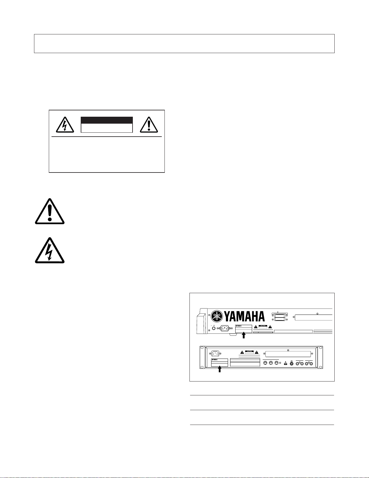
NAME PLATE LOCATION: The graphic below indicates the location
of the name plate. The model number, serial number, power
requirements, etc., are located on this plate. You should record the
model number, serial number, and the date of purchase in the spaces
provided below and retain this manual as a permanent record of your
purchase.
Model
Serial No.
Purchase Date
92-469- 1 (rear)
CAUTION
RISK OF ELECTRIC SHOCK
DO NOT OPEN
CAUTION: TO REDUCE THE RISK OF
ELECTRIC SHOCK, DO NOT REMOVE
COVER (OR BACK). NO USER-SERVICEABLE
PARTS INSIDE. REFER SERVICING TO
QUALIFIED SERVICE PERSONNEL.
CS6x
AC INLET
POWER
ON OFF
3.3V
CARD
CS6R
AC INLET
MIDI
OUT
THRU IN
HOST SELECT
OUTPUT
TO HOST
INDIVIDUAL OUTPUT
2
1
R
L MONO
PC-1PC-2
Mac
MIDI
Page 3
PRECAUTIONS
PLEASE READ CAREFULLY BEFORE PROCEEDING
* Please keep these precautions in a safe place for future reference.
WARNING
Always follow the basic precautions listed below to avoid the possibility of serious injury or even death from electrical shock,
short-circuiting, damages, fire or other hazards. These precautions include, but are not limited to, the following:
• Only use the voltage specified as correct for the instrument. The required
voltage is printed on the name plate of the instrument.
• Always connect the three-pin attachment plug to a properly grounded power
source. (For more information about the main power supply, see page 12.)
• Before cleaning the instrument, always remove the electric plug from the
outlet. Never insert or remove an electric plug with wet hands.
• Check the electric plug periodically and remove any dirt or dust which may
have accumulated on it.
• This instrument contains no user-serviceable parts. Do not attempt to
disassemble or modify the internal components in any way.
• Do not expose the instrument to rain, use it near water or in damp or wet
conditions, or place containers on it containing liquids which might spill
into any openings.
• If the power cord or plug becomes frayed or damaged, or if there is a
sudden loss of sound during use of the instrument, or if any unusual smells
or smoke should appear to be caused by it, immediately turn off the power
switch, disconnect the electric plug from the outlet, and have the instrument
inspected by qualified Yamaha service personnel.
CAUTION
Always follow the basic precautions listed below to avoid the possibility of physical injury to you or others, or damage to the
instrument or other property. These precautions include, but are not limited to, the following:
• Do not place the power cord near heat sources such as heaters or radiators,
and do not excessively bend or otherwise damage the cord, place heavy
objects on it, or place it in a position where anyone could walk on, trip over,
or roll anything over it.
• When removing the electric plug from the instrument or an outlet, always
hold the plug itself and not the cord. Pulling by the cord can damage it.
• Do not connect the instrument to an electrical outlet using a multipleconnector. Doing so can result in lower sound quality, or possibly cause
overheating in the outlet.
• Remove the electric plug from the outlet when the instrument is not to be
used for extended periods of time, or during electrical storms.
• Before connecting the instrument to other electronic components, turn off
the power for all components. Before turning the power on or off for all
components, set all volume levels to minimum. Also, be sure to set the
volumes of all components at their minimum levels and gradually raise the
volume controls while playing the instrument to set the desired listening
level.
• Do not expose the instrument to excessive dust or vibrations, or extreme
cold or heat (such as in direct sunlight, near a heater, or in a car during the
day) to prevent the possibility of panel disfiguration or damage to the
internal components.
• Do not use the instrument near other electrical products such as televisions,
radios, or speakers, since this might cause interference which can affect
proper operation of the other products.
• Do not place the instrument in an unstable position where it might
accidentally fall over.
• Before moving the instrument, remove all connected cables.
• When cleaning the instrument, use a soft, dry cloth. Do not use paint
thinners, solvents, cleaning fluids, or chemical-impregnated wiping cloths.
Also, do not place vinyl, plastic or rubber objects on the instrument, since
this might discolor the panel or keyboard.
• Do not rest your weight on, or place heavy objects on the instrument, and do
not use excessive force on the buttons, switches or connectors.
• Use only the stand/rack specified for the instrument. When attaching the
stand or rack, use the provided screws only. Failure to do so could cause
damage to the internal components or result in the instrument falling over.
• Do not operate the instrument for a long period of time at a high or
uncomfortable volume level, since this can cause permanent hearing loss. If
you experience any hearing loss or ringing in the ears, consult a physician.
■ REPLACING THE BACKUP BATTERY
• This instrument contains a non rechargeable internal backup battery which
permits internal data to remain stored even when the power is off. When the
backup battery needs replacing, the message "Change internal battery." will
display in the LCD. When this happens, immediately back up your data, then
have qualified Yamaha service personnel replace the backup battery.
• Do not attempt to replace the backup battery yourself, in order to prevent the
possible serious hazards. Always have qualified Yamaha service personnel
replace the backup battery.
• Never place the backup battery in a location that a child can reach, since a
child might accidentally swallow the battery. If this should happen, consult a
physician immediately.
■ SAVING USER DATA
• Always save data to a Memory Card (SmartMedia) frequently, in order to
help prevent the loss of important data due to a malfunction or user
operating error.
Yamaha cannot be held responsible for damage caused by improper use or
modifications to the instrument, or data that is lost or destroyed.
Always turn the power off when the instrument is not in use.
(2)-6
Page 4
4
Introduction
Thank you for purchasing the Yamaha CS6x/CS6R Control Synthesizer.
Your new CS6x/CS6R synthesizer incorporates the highly-acclaimed AWM2 synthesis engine,
allowing the creation of super-realistic sounds. It also supports optional Plug-in Boards that provide
other synthesis engines of your choice, enabling the production of cutting edge synthesizer sounds.
You can play all these sounds using the synthesizer’s automatic playback facilities such as the built-in
Arpeggiator and Sequencer. Using the Phrase Clip feature, you can record real sounds or audio from
a CD, then play them back across the keyboard as you would a musical instrument.
Other features include Effects, Scenes (for storing sounds created with the Control Knobs on the front
panel), and Control Sets (for controlling various sound parameters in real time using different
controllers). These features make this synthesizer ideal for every kind of live performance or studio
work.
When editing a sound, you can use the [PAGE] knob to switch between screens and five other knobs
plus the [DATA] knob for changing parameter values. This makes the process of editing sounds much
easier and smoother. To make the most use of your synthesizer, you are encouraged to read through
this manual. After reading the manual, please keep it in a convenient and safe place for future
reference.
About This Manual
This manual is basically divided into two sections:
■ Basics Section (Page 6)
Explains how to get started with the synthesizer, its overall structure, and how to use its main features and
functions.
■ Reference Section (Page 74)
Explains the parameters in the synthesizer’s various Modes.
Package Contents
• Owner’s Manual (this book)
• Data List
• AC Power cord
• Memory Card (SmartMedia)
• Burglarproof Lock (Page 171)
• Installation Guide
• CD-ROM (TOOLS for S80 & CS6x/CS6R)
The Included CD-ROM
Application software and Phrase Clip audio files for your synthesizer are included on this CD-ROM. The Voice
Editor application lets you edit your synthesizer’s sounds through a graphical user interface. The Card Filer
application lets you exchange data between your synthesizer and computer. Details are given in the separate
Installation Guide or the on-line manuals included with the software.
Never attempt to play back the track1, in which the application software is located, on an audio CD player. Doing so may
result in damage to your hearing as well as to your CD player/audio speakers.
Copying of the commercially available music sequence data and/or digital audio files is strictry prohibited except for your personal use.
The illustrations and LCD screens as shown in this owner’s manual are for instructional purposes only, and may appear somewhat different from
those on your instrument.
The company names and product names in this Owner’s Manual are the trademarks or registered trademarks of their respective companies.
Page 5

5
Basics Section
The Controls & Connectors ................................6
Before Use ........................................................12
Power Supply ........................................................12
Connections ..........................................................13
Powering Up..........................................................19
Basic Operations ..............................................21
Selecting a Mode ..................................................21
Selecting a Screen ................................................23
Entering Data........................................................24
Demo Playback ................................................26
Voices and Performances ..................................27
Playing a Voice......................................................27
Playing a Performance..........................................29
An Overview of the CS6x/CS6R ....................31
Controller Section ................................................31
Sequencer Section ................................................31
Tone Generator Section ......................................32
Effects Section ......................................................34
About the Modes ..............................................35
Voices ................................................................36
An Overview of Voices/Waves ............................37
Waves ....................................................................38
Performances ....................................................39
Easy Real-time Editing ....................................40
Ideal for Playing Live ......................................41
1 Arpeggiator ........................................................42
2 Scene Controls (CS6x) ......................................45
3 Using Controllers ..............................................47
4 Phrase Clips ......................................................53
5 Other Useful Features ......................................59
Voice Edit..........................................................60
Effects....................................................................65
Using as a Master Keyboard
(Performance Mode) ........................................67
Using as a Multitimbral Tone Generator
(Performance Mode) ........................................72
Reference Section
Voice Mode........................................................74
Voice Play..............................................................74
Voice Edit ..............................................................78
Voice Job Mode ..................................................115
Voice Store ..........................................................116
Performance Mode ........................................117
Performance Play ..............................................117
Performance Edit ..............................................121
Performance Job Mode ......................................140
Performance Store ..............................................141
Phrase Clip Mode............................................142
Phrase Clip Play..................................................142
Phrase Clip Record ............................................143
Phrase Clip Edit..................................................146
Phrase Clip Job Mode ........................................154
Clip Kit Store ......................................................160
Sequence Play Mode ......................................161
Utility Mode....................................................163
Utility Job Mode ................................................170
Card Mode ......................................................171
Appendix
About the Plug-in Boards (Optional) ............177
Display Messages ............................................181
Troubleshooting..............................................182
Specifications ..................................................185
Index ..............................................................186
Table of Contents
Basics Section
Appendix
Reference
Section
Voice Mode
Performance
Mode
Phrase Clip
Mode
Sequence Play
Mode
Utility Mode
Card Mode
Page 6
FOOT
VOLUM
PHONES INDIVIDUAL OUTPUT
21
OUTPUT
L/MONO R
A/D INPUT
GAIN
LINE 1MIC/LINE 2
OCTAVE
VOLUME
DOWN UP
CUTOFF RESONANCE
ATTACK
1 2
DECAY S
CONTROL
R
FILTER EFFE
EG
SCENE PAN
GATE TIME
ON
/
OFF
ON
/
OFF
HOLD
PORTAMENTO PHRA
SEQ P
ARPEGGIO
P
T
CUTOFF RESONANCE
ATTACK
1 2
DECAY SUSTAIN
CONTROL PAN
RELEASE
REVERB CHORUS
FILTER EFFECT
EG
SCENE PAN
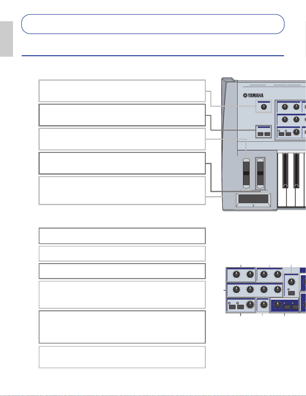
1 [VOLUME] Knob (Page 20)
Adjusts the master volume. Turn the knob clockwise to raise the output level from the
OUTPUT L/R jacks and the PHONES jack.
2 OCTAVE [UP] and [DOWN] keys (Page 28) (CS6x only)
Press either of these keys to shift the note range of the keyboard up or down in octaves.
Press them together to returns to the standard range (0).
3 PITCH bend wheel (Page 47) (CS6x only)
Controls the pitch bend effect. You can also assign other functions to this controller.
4 MODULATION wheel (Page 47) (CS6x only)
Controls the modulation effect. You can also assign other parameters functions to this
controller.
5 Ribbon Controller (Page 48) (CS6x only)
Touch and slide your finger horizontally across the controller’s surface to continuously
change a specific parameter’s value. You can also assign various functions to this
controller.
6-1 FILTER knobs (Page 40)
These two knobs offer dynamic and real-time tonal changes to a sound.
6-6 [PAN] knob (Page 59)
Use this knob to adjust the stereo pan position of the current sound (i.e., the sound’s
position in the stereo image).
6-2 EFFECT knobs (Page 40)
These knobs respectively control depths(send level) of the Reverb and Chorus effects.
6-3 EG knobs (Page 40)
These four knobs control variances in pitch, tone, and volume.
6-4 PORTAMENTO controls (Page 59)
This section consists of the PORTAMENTO [ON/OFF] key and a knob for adjusting
Portamento Time. With Portamento enabled, there will be a smooth transition in pitch
from one note to the next. The Portamento Time is the speed of the transition.
6-5 SCENE controls (Page 46)
Pressing either SCENE key ([1] or [2]) to recall the stored knob settings. The LED for the
key of the current Scene is lit. The [CONTROL] knob can be used to create a smooth
transition between two Scenes. You can also set up the Modulation Wheel or a Foot
Controller to like the SCENE [CONTROL] knob (Page 46).
6-1 6-2
6-3
6-4
6-5 6-6 6-7
CS6x
6
Basics
Section
Basics
Section
Basics Section
The Controls & Connectors
Front Panel
Page 7
MIDIHOST SELECTTO HOSTBREATH
FOOT
SWITCH
FOOT
CONTROLLER
OUTIN THRU
SUSTAIN
VOICE PERFORM
UTILITY CARD
EDIT
COMPARE
JOB
STORE
MODE
GATE TIME
ON
/
OFF
PLAY
/
STOP
REC
ON
/
OFF
HOLD
PORTAMENTO PHRASE CLIP
SEQ PLAY
ARPEGGIO
PITCH
TEMPO
PAN
RELEASE
PLAY
/
STOP
REC
EMPO
CARD
3.3V
ELEMENTPARTPAGE
SHIFT
CURSOR
VOICE
PERFORM
PHRASE
CLIP
UTILITY
CARD REC
JOB
STORE
EDIT
COMPARE
SEQ
PLAY
EF
BYPASS
PLAY
STOP
GAIN
VOLUME
BREATH PHONES
LINE1
MIC
LINE 2
A D INPUT
SYSTEM BA
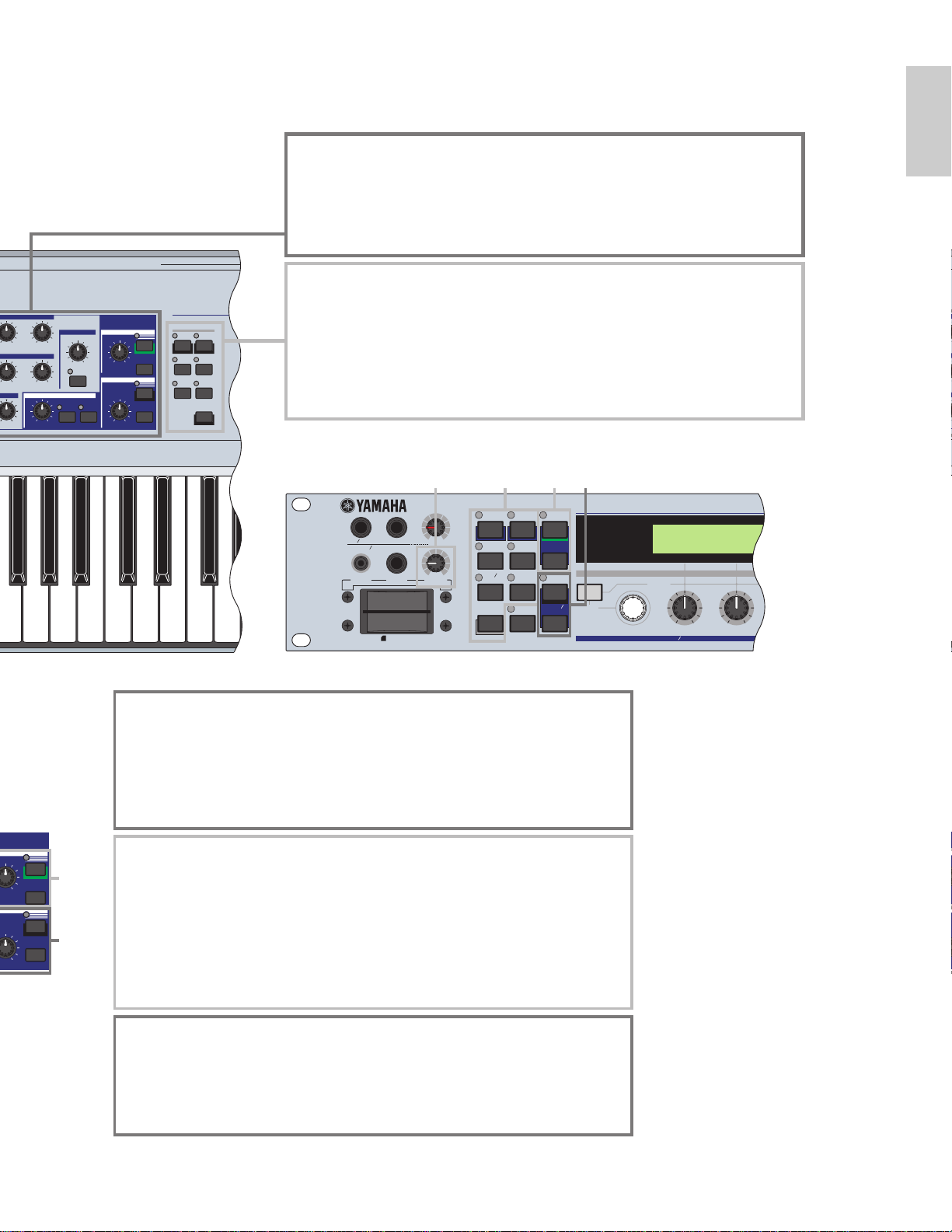
6-7 ARPEGGIO controls (Page 42)
Press the [ON/OFF] key to enable or disable the Arpeggiator. The Arpeggiator plays
according to the arpeggio settings for each Voice or Performance. Use the [GATE TIME]
knob to adjust the playback length of each note in the arpeggio (Page 42). Press the
[HOLD] key (its LED will light) to have the Arpeggiator continue playback even after you
release the notes. To stop the arpeggio, press the HOLD key again (the LED turn off).
6-8 PHRASE CLIP controls (Page 53)
Press the PHRASE CLIP key to enter Phrase Clip Play Mode (the LED will light). Then
press the [REC] key to enter Phrase Clip Record Mode. In this Mode, you can record a
Phrase Clip (waveform data) using an external microphone, then treat the sound as a
musical instrument. The [PITCH] knob changes the Phrase Clip’s pitch (or its tempo if the
Phrase Clip is rhythmic).
With the CS6R, you can play back (audition) the sound by pressing the PHRASE CLIP
key in Phrase Clip Mode at note C3 and with a velocity of 127
6-9 SEQ controls (Pages 26, 161)
Press the [SEQ] key to enter Sequence Play Mode. Here, you can play a MIDI file from
Memory Card. Use the [PLAY/STOP] key to start or stop playback of the currently
selected file. You can use the [TEMPO] knob to adjust the playback speed.
6 Sound Control knobs (Page 40) (CS6x only)
You can modify the effects and tones in real time using these. There are knobs for Filter
Cutoff Frequency and Resonance, the time parameter of the Envelope Generator (EG),
and Reverb and Chorus effects. Other controls are related to the Arpeggiator, Portamento,
Phrase Clip, and Sequencer.
7 MODE keys (Page 21)
Press these to keys to select Voice, Performance, Utility or other Modes.
With the CS6R, you can play back (audition) the Voice at note C3 and with a velocity of 127
by pressing the [VOICE] key in Voice Play Mode.
Similarly, in Performance Play Mode, pressing the [PERFORM] key plays back Voices for
the Parts (Layer Switch set to "on") at note C3 with a velocity value of 127.
6-8
6-9
CS6R
71 6-8 6-9
7
Basics
Section
Page 8
8
Basics
Section
Basics
Section
THRU
DEC/NO INC/YES
EXIT ENTER
EF
BYPASS
MASTER
KEYBOARD
SYSTEM
CURSOR
A B C 1 2
SHIFT PAGE PART
/
ELEMENT DATA
CARD
3.3V
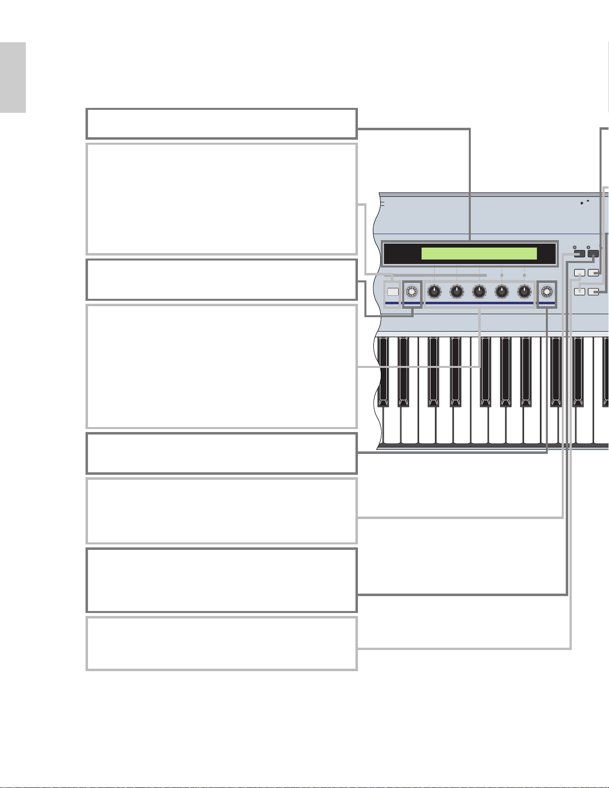
8 LCD (Liquid Crystal Display)
This is a backlit 2-line display.
) [PAGE] knob (Page 23)
Switches between screens in each Mode. Each Mode includes several
screens.
! Knobs [A], [B], [C], [1] and [2] (Page 24)
In each Play Mode, these knobs mainly control the functions respectively
assigned to them. In each Edit Mode, each knob is used to enter a value
for the associated parameter shown in the display. Depending on the
operation or the screen you are working in, these knobs will function
differently.
Knobs [A] to [C] can be assigned to system control functions (Page 165).
Knobs [1] and [2] can be assigned control functions that affect Voices
(Page 84).
@ [DATA] knob (Page 25)
Use this to increase or decrease the value of the parameter at which the
cursor is positioned.
# [EF BYPASS] key (Page 66)
Enables/dsiables the Effect Bypass. Press the key (its LED will light) to
bypass the effects used with the current Voice or Performance.
The bypassed effects (Reverb, Chorus, or Insertion) are specified in Utility
Mode (Page 164).
$ [MASTER KEYBOARD] key (pages 67, 121) (CS6x only)
The S80 keyboard can work as MIDI master keyboard in Performance
mode. When the key is pressed and switched on (the LED will light), the
keyboard can play and control multiple MIDI sound modules connected to
the S80.
% [EXIT] key (Page 23)
The menus and screens of the S80 have a hierarchical structure. Press
this key exit from the current screen and return to the previous level in the
hierarchy.
9 [SHIFT] key (Page 23)
In Voice or Performance Play Mode, a screen for viewing or setting the
Octave parameter and the MIDI Transmit channel (Page 23) is shown
when you press the [SHIFT] key. In any of the Edit Modes, when
pressing this key while turning the [PAGE] knob, a menu screen is
displayed and you can quickly switch between Edit Mode screens (Page
23). If while holding this key you turn one of Knobs [A] ~ [D], [1] ~ [2],
[DATA] knob, or press either [INC/YES] or [DEC/NO] key, you can move
the cursor without a parameter value being changed (Page 24).
CS6x
Page 9
9
Basics
Section
POWER
BANK
PROGRAM
PART
A B C D E F G H
1 2 3 4 1 2 3 4
ELEMENT SELECT ELEMENT ON
/
OFF
1 2 3 4 5 6 7 8
9 10 11 12 13 14 15 16
GENERAL QED ARPEGGIO CONTROL COM LFO EFFECT
OSC PITCH FILTER AMPLITUDE LFO EQ PLG
MEMORY
PRE1
INT EXT
PLG1 PLG2
PRE2
DRUM
DRUM
POWER
PLG1INTPRE1
PLG2EXTPRE2
EXIT
DATA
ELEMENTPARTPAGE
SHIFT
CURSOR
VOICE
ENTER
DEC NO
INC YES
DRUM DRUM
MEMORY
ON
OFF
PERFORM
PHRASE
CLIP
UTILITY
CARD REC
JOB
STORE
EDIT
COMPARE
SEQ
PLAY
EF
BYPASS
PLAY
STOP
SYSTEM BA
21
C
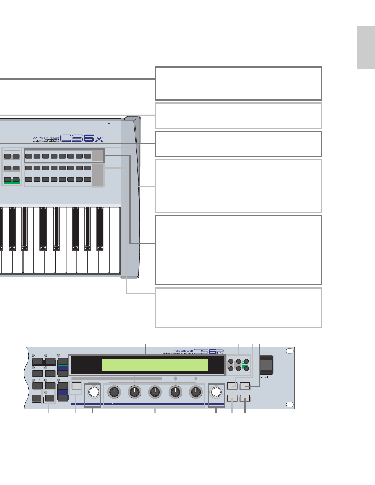
^ [ENTER] key (Pages 24, 25)
While selecting a Memory or Bank for Voice or Performance, press this
key to determine such a memory location. Also, use this key to execute a
Job or a Store operation.
& [DEC/NO] key (Page 24)
Use this to decrease the value of the parameter at which the cursor is
positioned. Also use it to cancel a Job or a Store operation.
* [INC/YES] key (Page 24)
Use this to increase the value of the parameter at which the cursor is
positioned. Also use it to execute a Job or a Store operation.
( MEMORY keys (Pages 27, 29, 75, 119)
Using one of these keys, you can select a Voice or Performance
Memory. Press the [ENTER] key ^ to select the Memory. In
Performance Mode, the [INT], [EXT], [PLG1] and [PLG2] keys can be
used to select the Phrase Clip Part, A/D Part, Plug-in 1 Part and Plug-in 2
Part. The [PRE1] and [PRE2] keys select “Common” (for all Parts).
º BANK [A] to [H] keys (Pages 75, 119)
Each key selects a Voice or Performance Bank. Each Bank contains
sixteen Voices or Performances. In Voice Edit Mode, each of the BANK
[A] to [D] keys selects a Voice’s Element (ELEMENT SELECT) while
each of the BANK [E] to [H] keys turns the associated Voice’s Element on
or off (ELEMENT ON/OFF). When you activate Master Keyboard Mode
by pressing the [MASTER KEYBOARD] key $, these keys can
respectively select Zones 1 to 4 if the Master Keyboard Mode setting is
“4zone” in Performance Edit Mode.
¡
PROGRAM/PART [1] to [16] keys (Pages 76, 119)
Each key selects a Voice or Performance from the current Bank. In Voice
Edit Mode, each PROGRAM/PART key selects an associated edit menu.
In Performance Mode, these keys select Parts [1] to [16], respectively.
# 9 ) ! @ & *
8 ( % ^
CS6R
Page 10
10
Basics
Section
Basics
Section
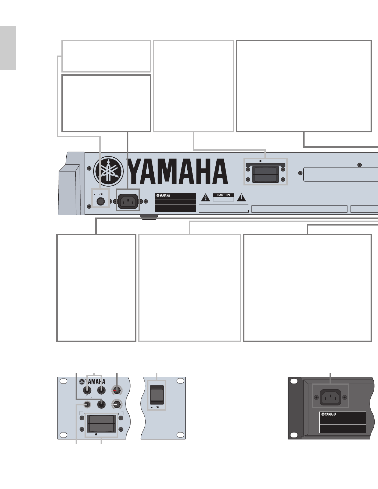
Rear Panel
CARD
3.3V
AC INLET
POWER
ON OFF
CARD
3.3V
GAIN
VOLUME
BREATH PHONES
LINE1
MIC
LINE 2
A D INPUT
POWER
ON
OFF
AC INLET
1 POWER switch (Page 19)
Use this to switch the synthesizer
on or off.
) FOOT CONTROLLER jack
(Pages 18, 48) (CS6x only)
An optional foot controller
(FC7, etc.) can be connected
here. Using the foot controller,
you can control tones, pitches,
volumes or the like by foot.
! FOOT VOLUME jack
(Pages 18, 48) (CS6x only)
An optional foot controller (FC7, etc.) can
be connected here. You can control the
output level from the instrument by foot.
In Utility Mode, you can select Volume or
Expression for this controller.
@ INDIVIDUAL OUTPUT 1 and 2 jacks (Page 13)
Line level audio signals are output from the
synthesizer via these phone jacks (1/4" mono phone
plug). The output is separated from that at the
OUTPUT L/MONO and R jacks. In Performance
Mode, you can specify which Parts can be output from
these separate outputs.
2 AC INLET terminal (Page 12)
Plug the female end of the supplied
AC power cord in here before
plugging it into an AC wall outlet.
3 CARD slot (Page 171)
Insert a Memory Card here to
transfer various data to/from
the instrument. Read carefully
the precautions on use of a
Memory Card (Page 171)
before using a card.
4 MIDI IN, OUT, and THRU connectors (Page 15)
MIDI IN receives MIDI messages from an external MIDI
device. Use this connector to control the synthesizer from
an external MIDI device. MIDI OUT sends out MIDI
messages generated by the synthesizer, such as notes
played on the keyboard or panel control/knob variations,
to an external MIDI sound module or device. MIDI THRU
just reflects the MIDI messages received at MIDI IN.
Connect other MIDI devices here.
CS6x
CS6R
$ % ^ 1 2
& 3
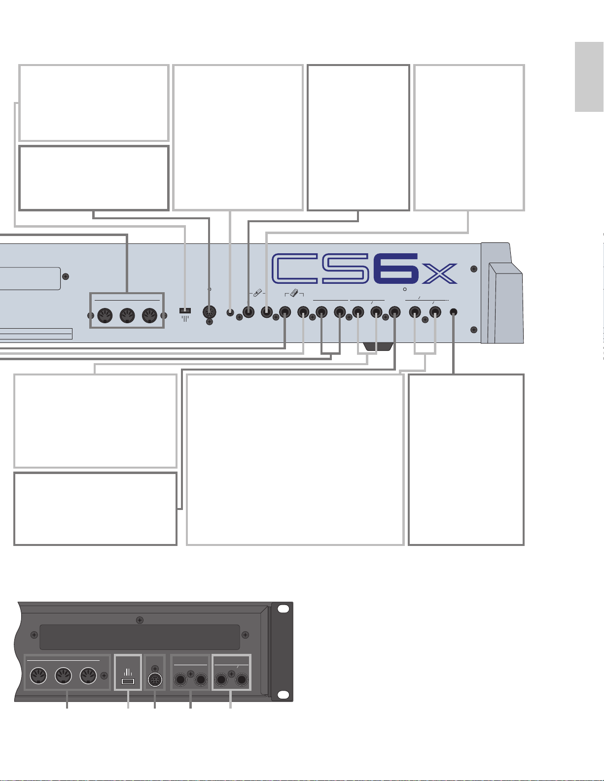
Page 11
11
Basics
Section
MIDI
OUTTHRU IN
HOST SELECT
Mac
PC-1PC-2
MIDI
TO HOST BRE ATH
SUSTAIN
FOOT
SWITCH
FOOT
CONTROLLER
FOOT
VOLUME
INDIVIDUAL OUTPUT
1
2
OUTPUT
R L MONO
PHONES LINE 1 MIC
LINE 2
A D INPUT
GAIN
OUTPUT
R
L MONO
TO HOST
MIDI
OUT
THRU IN
INDIVIDUAL OUTPUT
1
2
HOST SELECT
Mac
PC-1PC-2
MIDI
8 FOOT SWITCH
jack (Pages 18, 48)
Connect an optional
Foot switch (FC4 or
FC5) here. Using the
foot switch, you can
control of a range of on
or off a specific function
by foot, as assigned on
the instrument. (Pages
53, 165)
9 SUSTAIN jack
(Pages 18, 48)
An optional Foot Switch
(FC4 or FC5) can be
connected here. You can
use the Foot Switch as a
damper pedal on the
acoustic piano or for a
sustained effect.
$ PHONES jack (Page 13)
Connect a pair of headphones here.
# OUTPUT L/MONO and R jack (Page 13)
Line level audio signals are output via
these phone jacks. For monophonic
output, use just the L/MONO jack.
^ GAIN knob
(Pages 73, 144
)
Use this to adjust the input
gain of the audio signals at
the A/D INPUT jacks. You
may need to adjust this
depending on the type of
device (microphone, other
instrument output, etc.)
connected when using a
A/D Input part.
% A/D INPUT jacks (Page 14)
External audio signals can be input via these phone jacks.
Use these when recording Phrase Clips by connecting a
microphone or other audio equipment. To record a
monophonic line level signal, you use LINE 1. Use
MIC/LINE 2 to record a microphone level signal. To
record a stereo line level signal, use both jacks. However,
stereo signals are merged into a monophonic signal
internally when recording.
5 HOST SELECT switch (Page 16)
Select the type of computer
connected to the synthesizer via the
TO HOST connector .
6 TO HOST terminal
Connect a computer here using an
optional serial computer cable
(Page 16).
7 BREATH jack (Pages 18, 48)
Connect an optional breath
controller BC3 here. You can
use the Breath Controller to
change the output level or tone
of the sounds according to the
strength of your breath.
4 5 6 @ #
Page 12
12
Before Use
This section explains how to connect to an AC power source, audio and MIDI devices, and a computer
system. Only switch the synthesizer on after you have made all the necessary connections.
It is recommended that you read this section before using the synthesizer.
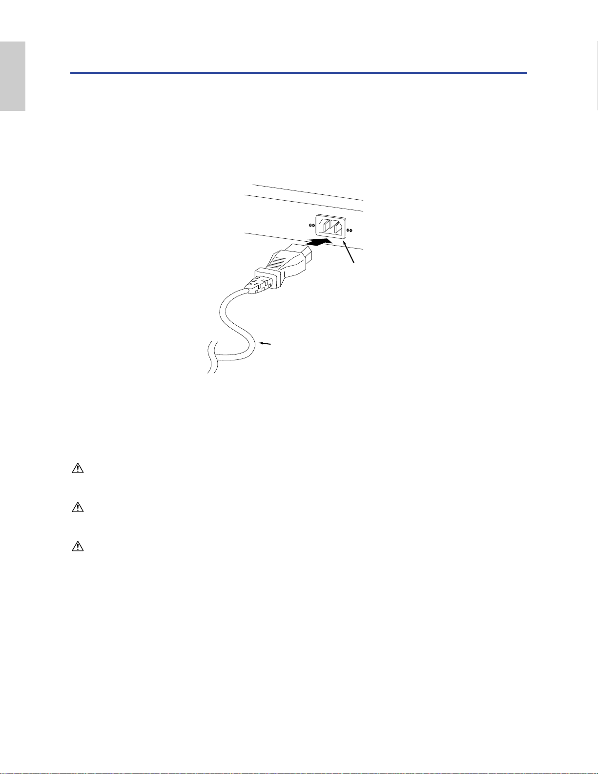
Power Supply
1Make sure that the instrument’s POWER switch is at the OFF position.
2Connect the supplied power cord to the AC INLET terminal on the instrument’s rear panel.
3Connect the other end of the power cord to an AC outlet. Make sure the synthesizer meets the
voltage requirement for the country or region in which it is being used.
Make sure your CS6x/CS6R is rated for the AC voltage supplied in the area in which it is to be used (as listed on
the rear panel). Connecting the unit to the wrong AC supply can cause serious damage to the internal circuitry
and may even pose a shock hazard!
Use only the AC power cord supplied with the CS6x/CS6R. If the supplied cord is lost or damaged and needs to
be replaced, contact your Yamaha dealer. The use of an inappropriate replacement can pose a fire and shock
hazard!
The type of AC power cord provided with the CS6x/CS6R may be different depending on the country in which it
is purchased (a third prong may be provided for grounding purposes). Improper connection of the grounding
conductor can create the risk of electrical shock. Do NOT modify the plug provided with the CS6x/CS6R. If the
plug will not fit the outlet, have a proper outlet installed by a qualified electrician. Do not use a plug adapter
which defeats the grounding conductor.
Power cord
(included)
CS6x/CS6R
rear panel
AC INLET terminal
Basics
Section
Page 13
13
Basics
Section
Connections
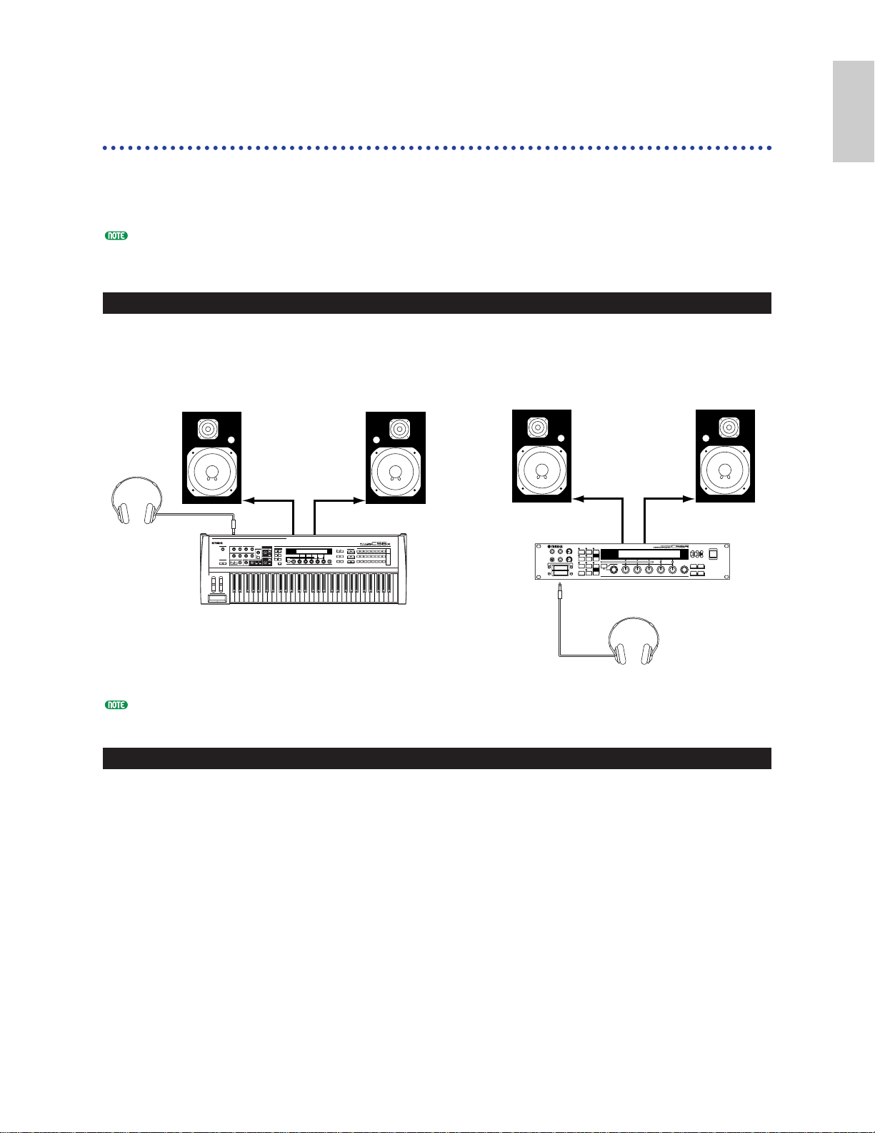
Connecting to External Audio Equipment
Since the synthesizer has no built-in speakers, you need to monitor its sound output via external
audio equipment. Alternatively, you could use a pair of headphones.
There are several methods of connecting to external audio equipment, as described in the following
illustrations.
The CS6R also needs an external MIDI controller such as a keyboard, though this is not necessary when using
the internal sequencer. For MIDI connections, see the next section.
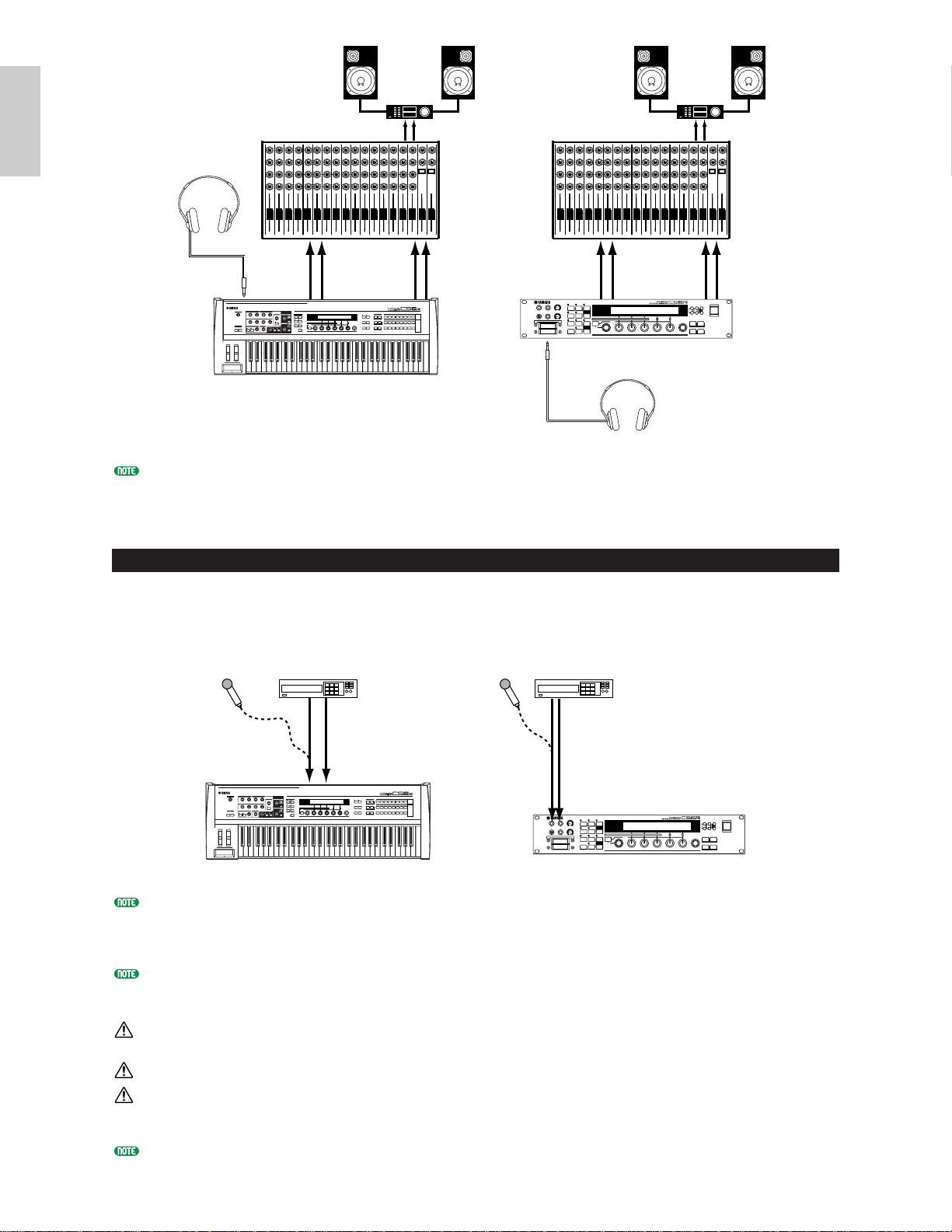
Connecting Stereo Powered Speakers
A pair of powered speakers can accurately produce the instrument’s rich sounds with their own pan
and effect settings. Connect your powered speakers to the OUTPUT L/MONO and R jacks on the
rear panel.
When using just one powered speaker, connect it to the OUTPUT L/MONO jack on the rear panel.
Connecting to a Mixer
There are extra audio outputs in addition to the OUTPUT (L/MONO and R) jacks. These four
outputs can connect to a mixer for separately controlling the outputs of up to four Parts in
Performance Mode (Page 117). You can specify the output routing of each Part in Performance Edit
Mode (Page 133).
Powered speaker (Left) Powered speaker (Right)
OUTPUT
L/MONO
PHONES
OUTPUT R
CS6R
Headphones
Headphones
Powered speaker (Left) Powered speaker (Right)
INPUTINPUT INPUTINPUT
PHONES
OUTPUT
L/MONO
OUTPUT R
C
CS6x
Page 14
14
Basics
Section
Connecting a pair of headphones does not affect audio output from the OUTPUT (L/MONO and R) jacks.
You can monitor the same sounds via headphones and at the OUTPUT jacks. However, you cannot monitor the
sounds from INDIVIDUAL OUTPUT 1 and 2 with headphones.
Connecting a Microphone or Other Audio Equipment
You can record or import external sounds or waveform data and use them as instrument sounds
(Phrase Clips, see Page 142). When recording from an external audio source, connect a microphone or
the audio source to the A/D INPUT (LINE 1 and MIC/LINE 2) jacks.
LINE 1 and MIC/LINE 2 can receive monophonic signals. To input a monophonic line level signal to the
instrument, use only LINE 1. Use MIC/LINE 2 to input a microphone level signal. When you input stereo line
signals, use both jacks. However, these stereo signals are internally merged into a monophonic signal for use in a
later process.
After the above connections are complete, you are ready to set up for recording. When starting a recording, you
may need to adjust the input gain of the audio source using the GAIN knob. Details about Phrase Clips,
including how to adjust the input gain, are given on Page 142.
If you choose the wrong type of input source (Pages 130, 144), you may possibly damage your hearing and/or any
connected audio equipment. Make sure you set this parameter correctly.
Before connecting a device to the A/D INPUT jack, always turn the GAIN knob all the way down.
Do not use both LINE1 and MIC/LINE2 at the same time except for when you want to input stereo line level
signals, which will be mixed into a mono signal on the instrument. If you fail to do so, the external device
connected may be damaged.
You can connect an external audio source to the A/D Input Part and use it as a Part in a Performance. Details are
given on Pages 73, 130.
Speaker
Speaker
Amplifier
OUTPUT L
INDIVIDUAL
OUTPUT1
R
INDIVIDUAL
OUTPUT2
R
Headphones
PHONES
OUTPUT L
INDIVIDUAL
OUTPUT1
Amplifier
L
Mixer
12345678910111213141516LR
OUTPUT L /
MONO
R
C
R
INDIVIDUAL
OUTPUT2
R
Mixer
1 2 3 4 5 6 7 8 9 10 11 12 13 14 15 16 L R
OUTPUT L /
MONO
PHONES
L
R
CS6R
CS6x
Headphones
CD Player or other audio equipment
(merged to mono internally)
RL
Microphone
(mono devices)
MIC/LINE2 LINE1
C
CS6x
CD Player or other audio equipment
(merged to mono internally)
RL
Microphone
(mono devices)
MIC/LINE2 LINE1
CS6R
Page 15
15
Basics
Section
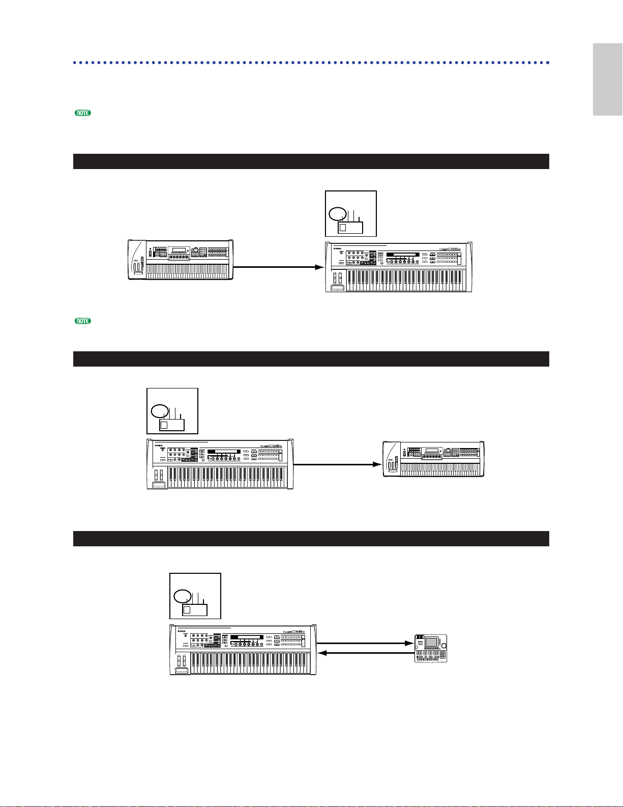
Connecting External MIDI Equipment
You can connect an external MIDI device using a MIDI cable (available separately) and control it from
this synthesizer. You can also use an external MIDI keyboard or sequencer to control the
synthesizer’s internal sounds. This section introduces several different applications of MIDI.
The HOST SELECT switch on the rear panel should be set to “MIDI.” Otherwise, MIDI information will not be
transmitted from the synthesizer’s MIDI OUT connector.
Controlling from an External MIDI Keyboard
The CS6R has no built-in keyboard so the above MIDI connection lets you play it in realtime.
Controlling an External MIDI Keyboard
Recording and Playback using an External MIDI Sequencer
MIDI IN
MIDI OUTMIDI IN
MIDI OUT
External MIDI
sequencer
CS6x/CS6R
C
HOST SELECT
PC-2 PC-1
MIDI Mac
MIDI OUT
MIDI IN
External MIDI keyboard
or synthesizer
CS6x/CS6R
C
HOST SELECT
PC-2 PC-1
MIDI Mac
HOST SELECT
PC-2 PC-1
MIDI Mac
C
CS6x/CS6R
External MIDI keyboard
or synthesizer
MIDI OUT
MIDI IN
Page 16
16
Basics
Section
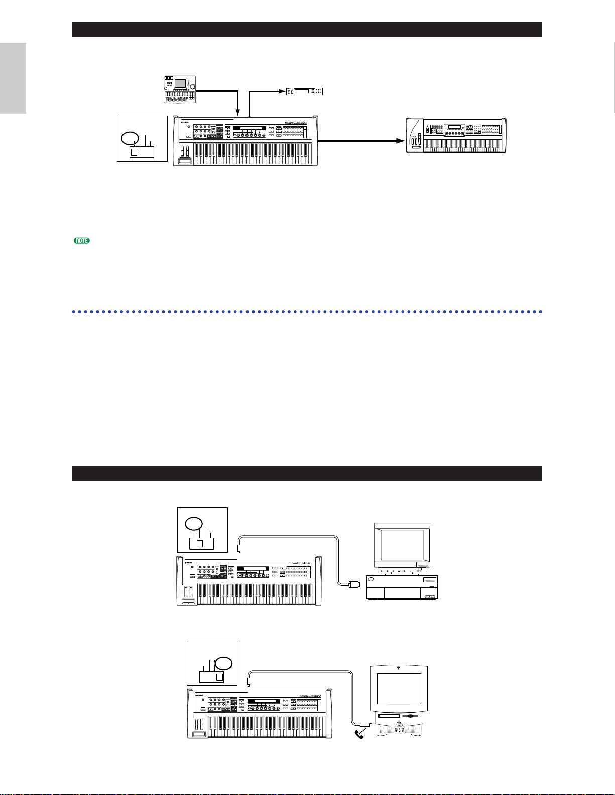
Controlling Another MIDI Device via MIDI THRU
With the above MIDI connections, you can send MIDI data from the MIDI OUT connector while
MIDI data from the external sequencer can be sent to an external MIDI synthesizer via the MIDI
THRU jack.
The MIDI cable should be no greater than 15 meters in length, and there should be no more than three devices in
a MIDI chain (chained in series via each unit’s MIDI THRU). To connect more units, use a MIDI Thru Box for
parallel connections. You may encounter errors if the MIDI cables are too long or if too many devices are chained
together via their MIDI THRU connectors.
Connecting to a Personal Computer
When a computer is connected, it can be used to control the synthesizer and to transfer synthesizer
data to/from computer via MIDI. With the included Voice Editor program, for instance, you can edit
the synthesizer’s Voices. Using another program – Card Filer – you can transfer files between the
computer and the Memory Card inserted in the synthesizer’s CARD slot.
There are two ways to connect your synthesizer to a computer:
1: Serial connection (the computer’s serial port to the synthesizer’s TO HOST terminal)
2: MIDI connection (the computer’s MIDI interface or external MIDI interface to the
synthesizer’s MIDI IN and OUT)
Different computers require different connections, as follows.
1: Serial Port to TO HOST
IBM PC/AT
Macintosh
TO
HOST
Serial cable
HOST SELECT
PC-2 PC-1
MIDI Mac
Apple Macintosh
PS422
(Modem or
Printer port)
CS6x/CS6R
C
IBM PC/AT and compatibles
RS-232C
(DB9)
IBM
Personal System/V
PS/V
Personal System/V
TO
HOST
Serial cable
HOST SELECT
PC-2 PC-1
MIDI Mac
CS6x/CS6R
C
External MIDI
sequencer
MIDI OUT
MIDI IN
External MIDI
synthesizer
MIDI THRU
C
MIDI OUT
MIDI IN
External MIDI synthesizer
HOST SELECT
PC-2 PC-1
MIDI Mac
MIDI IN
CS6x/CS6R
Page 17
17
Basics
Section
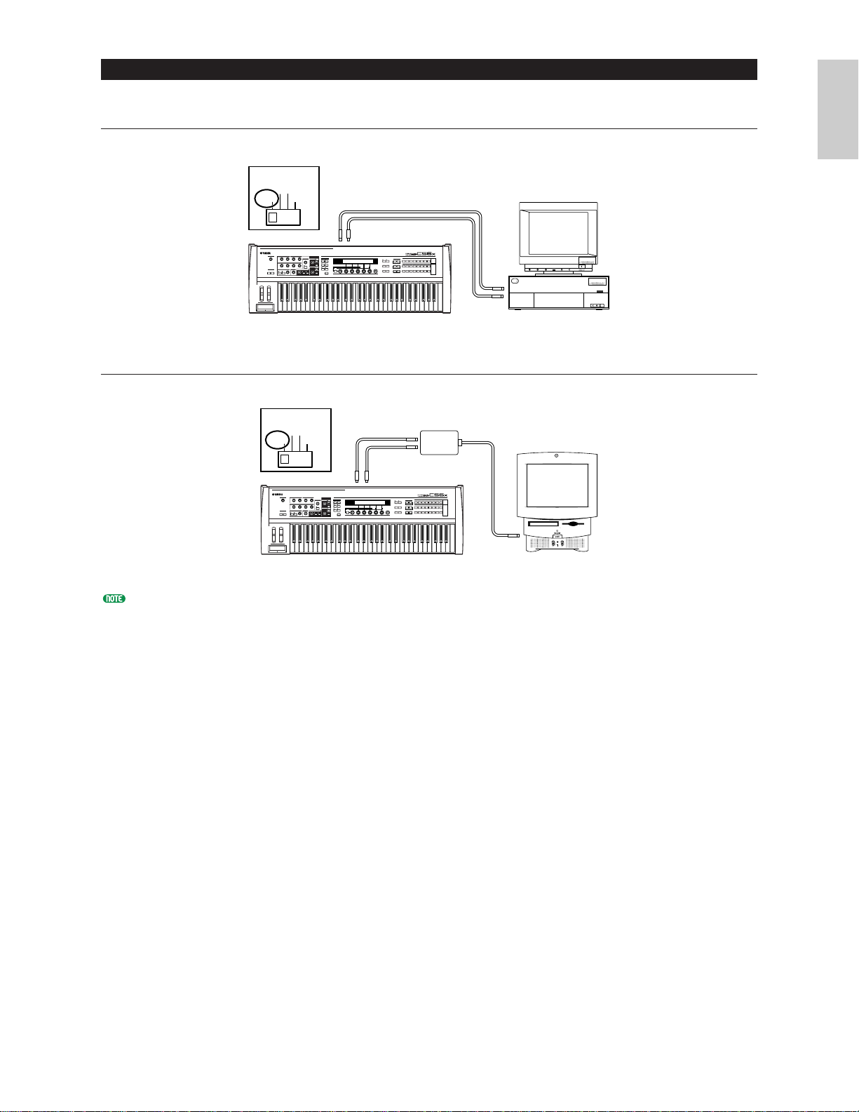
2: MIDI Interface to MIDI IN and OUT
Using the computer’s MIDI interface
Using an external MIDI interface
You will need to an appropriate MIDI application (sequencer, editor, etc.) for your computer platform.
HOST SELECT
PC-2 PC-1
MIDI Mac
MIDI IN
Serial cable
MIDI OUT
C
CS6x/CS6R
PS/V
MIDI
IBM
OUT
MIDI
IN
Computer with MIDI interface
Personal System/V
Personal System/V
HOST SELECT
PC-2 PC-1
MIDI Mac
MIDI IN MIDI OUT
C
CS6x/CS6R
MIDI Interface
MIDI OUT
MIDI IN
Computer
Page 18
18
Basics
Section
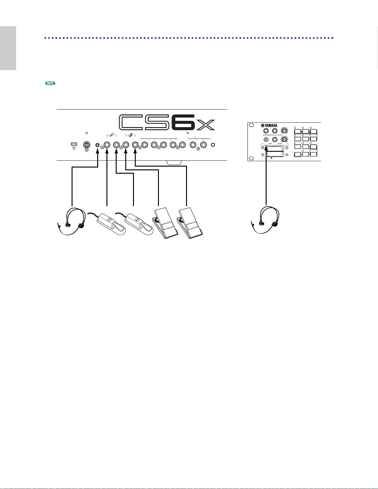
Connecting Various Controllers
The CS6x has several controller jacks on the rear panel, including FOOT SWITCH, SUSTAIN, FOOT
CONTROLLER, FOOT VOLUME and BREATH. You can connect optional controllers like a Foot
Switch (the FC4 or FC5), Foot Controller (the FC7) and Breath Controller (BC3, etc.) to control tone,
volume, pitch and other parameters. The CS6R only has a Breath Controller connector on its front
panel, but other controls (equivalent to the CS6x) may be available using external MIDI controllers.
Details about how to these controllers are given on Page 47.
CS6x
CARD
3.3V
VOICE
PERFORM
PHRASE
CLIP
UTILITY
CARD REC
JOB
STORE
EDIT
COMPARE
SEQ
PLAY
EF
BYPASS
PLAY
STOP
GAIN
VOLUME
BREATH PHONES
LINE1
MIC
LINE 2
A D INPUT
HOST SELECT
Mac
PC-1PC-2
MIDI
TO HOST BREATH
SUSTAIN
FOOT
SWITCH
FOOT
CONTROLLER
FOOT
VOLUME
INDIVIDUAL OUTPUT
1
2
OUTPUT
R L MONO
PHONES LINE1 MIC
LINE 2
A D INPUT
GAIN
CS6R
BREATH
BC3
FOOT
SWITCH
FC4
or
FC5
FC4
or
FC5
FC7 FC7BC3
FOOT
CONTROLLER
FOOT
VOLUME
BREATH
SUSTAIN
Page 19
19
Basics
Section
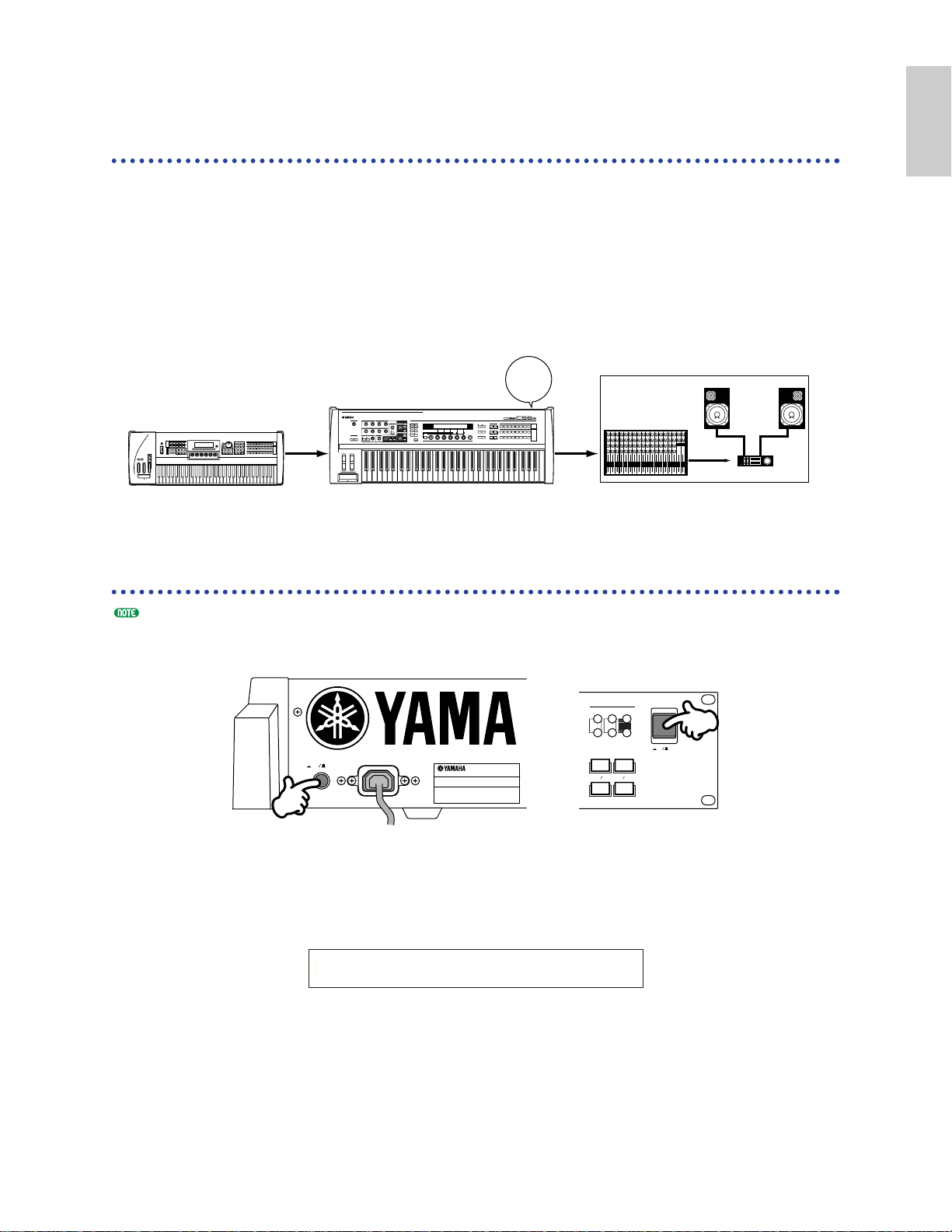
Powering Up
Power-on Procedure
When you have made all the necessary connections between your synthesizer and any other devices,
make sure that all volume settings are turned down all the way to zero. Then turn on the every device
in your setup in the order of MIDI masters (senders), MIDI slaves (receivers), then audio equipment
(mixers, amplifiers, speakers, etc.). This ensures the smooth flow of signals from the first device to the
last (first MIDI, then audio).
When powering down the setup, first turn down the volume for each audio devices, then switch off
each device in the reverse order (first audio devices, then MIDI).
When the CS6x/CS6R as MIDI receiver:
Switching the CS6x/CS6R On
Before you switch your synthesizer on or off, first turn down the volume of any audio equipment connected to it.
1Press the POWER switch.
2A splash screen is displayed briefly.
3The Voice or Performance Play Mode screen appears next.
VCE Play) PRE1:001(A01)[Sq:Generation]
EQLow-Q EQMid-G EQHi-G FLT-Rez HPF
CS6x
POWER
PLG1INTPRE1
PLG2EXTPRE2
EXIT ENTER
DEC NO
INC YES
DRUM DRUM
MEMORY
ON
OFF
AC INLET
POWER
ON OFF
CS6R
POWER
ON!!
C
1 2 3 4 5 6 7 8 9 10 11 12 13 14 15 16 L R
MIDI sender Audio equipment (first mixer, then amplifier)
CS6x/CS6R
(MIDI receiver)
Page 20
If you have a Memory Card inserted in the instrument’s CARD slot or an optional Plug-in Board
installed, you may see other screens before the Voice or Performance Play Mode screen is displayed.
If a previously used Memory Card is inserted in the CARD slot, you will see a screen while files in
EXT Memory are being loaded.
If a new Memory Card (one never used on the instrument) is inserted in the CARD slot, you will see
a screen while a basic file is being created in EXT Memory.
If you have a Plug-in Board installed, you will see a screen that confirms the presence of the Plug-in
Board.
The final screen after the power-on sequence may change depending on the Power On Mode setting available
Utility Mode (Page 164).
4Turn up the amplifier’s volume as necessary.
5Turn the synthesizer’s [VOLUME] knob clockwise to set an appropriate volume level.
About Memory Cards
You can save various kinds of data - Voice, Performance, Phrase Clip, Plug-in, Sequence Chain and so
on - onto Memory Card. The built-in CARD slot can accept 3.3-volt Memory Cards (SmartMedia),
and there is a Memory Card supplied with this synthesizer.
Before using a Memory Card, read through precautions on how to handle it (Page 171).
• Formatting a Memory Card
You cannot use a new Memory Card to save files immediately. The card must be formatted in Card
Mode (Page 176) beforehand. The Memory Card supplied with the synthesizer is already formatted
and contains Demo Song files.
• Saving and Loading Data
You can save various kinds of data as files on a formatted Memory Card. Each file on the card can be
loaded when required.
You can save and load data such as System, Voice, Performance, Phrase Clip, Plug-in, Sequence Chain
or the like. Since Phrase Clips or Sequence Chain data are held temporarily in the synthesizer’s
buffer memory and will be lost once you switch it off, you need to save such data onto the Memory
Card first.
Details about formatting a Memory Card, saving and loading data, and the recognized file types are
given on Page 172.
20
Basics
Section
Page 21
21
Basics
Section
Basic Operations
This section gives some basic explanations about operating the synthesizer.
Selecting a Mode
There are several operation Modes — Voice Play Mode, Performance Play Mode, Phrase Clip Mode,
etc. — each of which enables you to work efficiently with the synthesizer’s various functions.
An overview of each Mode is given on Page 35.
There are separate Play Modes for Voices, Performances and Phrase Clips. To enter each of these
Modes, use the appropriate MODE key ([VOICE] for Voice Play Mode, [PERFORM] for Performance
Play Mode). To enter or exit Phrase Clip Mode, press the PHRASE CLIP key. (Note that this key is
not found among the MODE keys.)
There are also separate Edit and Job Modes for Voices, Performances and Phrase Clips. To enter Edit
or Job Mode, simply press the [EDIT] or [JOB] key while in each respective Play Mode.
Similarly, pressing the [STORE] key in Voice, Performance or Phrase Clip (Play or Edit) Mode takes
you into Store Mode where you can store Voices, Performances or Phrase Clips.
Other Modes include Utility Mode where you can specify system settings, Card Mode where you can
perform tasks related to the Memory Card, and Sequence Mode where you can play back MIDI song
files or create a sequence chain. (Press the [UTILITY] key for Utility Mode, the [CARD] key for Card
Mode and the [SEQ] key for Sequence Mode.)
VOICE PERFORM
UTILITY CARD
EDIT
COMPARE
JOB
STORE
MODE
PLAY
/
STOP
REC
PHRASE CLIP
SEQ PLAY
PITCH
TEMPO
1
6
4
3
8
2
7
5
9
Play Modes
1 Voice Play Mode (Page 74)
Press the [VOICE] key (its LED
will light) to enter Voice Play
Mode. To exit to another Mode,
simply press the respective key
for that Mode.
2 Performance Play Mode
(Page 117)
Press the [PERFORM] key (its
LED will light) to enter
Performance Mode. To exit to
another Mode, simply press the
respective key for that Mode.
PFM Play) INT:001(A01) [--:Init Perf ]
EQLow-G EQMid-G EQHi-G ------- -------
VCE Play) PRE1:001(A01) [Sq:Generation]
EQLow-G EQMid-G EQHi-G FLT-Rez HPF
3 Phrase Clip Play Mode
(Page 142)
Press the [PHRASE CLIP] key
(its LED will light) to enter
Phrase Clip Play Mode. To exit
to another Mode, simply press
the respective key for that
Mode. If you press the [REC]
key while in Phrase Clip Play
Mode, the Record screen in
Phrase Clip Mode is displayed.
Edit Modes
When in each Play Mode, you
can swiftly switch to each
respective Edit Mode by simply
pressing the [EDIT] key (its
LED will light).
PCLP Play) 1(A01) [--:Init Voice]
EQLow-G EQMid-G EQHi-G ------- -------
4 Voice Edit Mode (Page 78)
Press the [EDIT] key in Voice
Play Mode. To exit to another
Mode, simply press the respective
key for that Mode or press the
[EXIT] key to return to Voice
Play Mode.
4 Performance Edit Mode
(Page 121)
Press the [EDIT] key while in
Performance Play Mode. To exit
to another Mode, simply press
the respective for that Mode or
press the [EXIT] key to return to
Performance Play Mode.
GEN Name) Ctgry a-Z 0-? Cursor
Common [--:Init Perf ]
GEN Name) Ctgry a-Z 0-? Cursor
C 1234 [Pf:Init Voice]
Page 22
22
Basics
Section
4
Phrase Clip Edit Mode (Page
146)
Press the [EDIT] key while in
Phrase Clip Play Mode. To exit
to another Mode, simply press
the respective key for that Mode
or press the [EXIT] key to
return to Phrase Clip Play Mode.
Job Modes
When in each Play Mode, you
can swiftly switch to each
respective Job Mode by simply
pressing the [JOB] key (its LED
will light).
5 Voice Job Mode (Page 115)
Press the [JOB] key in Voice Play
Mode. To exit to another Mode,
simply press the respective key
for that Mode or press the
[EXIT] key to return to Voice
Play Mode.
5 Performance Job Mode
(Page 140)
Press the [JOB] key while in
Performance Play Mode. To exit
to another Mode, simply press
the respective for that Mode or
press the [EXIT] key to return to
Performance Play Mode.
PFM Initialize)
Job Current Perform
VCE Initialize)
Job Current Voice
GEN Name) Ctgry a-Z 0-? Cursor
Common [--:Init Perf ]
5 Phrase Clip Job Mode
(Page 154)
Press the [JOB] key while in
Phrase Clip Play Mode. To exit
to another Mode, simply press
the respective key for that Mode
or press the [EXIT] key to
return to Phrase Clip Play
Mode.
5 Utility Job Mode (Page 170)
Press the [JOB] key in Utility
Mode. To exit to another Mode,
press the respective key for that
Mode or press the [EXIT] key to
return to Utility Mode.
Other Modes
6 Utility Mode (Page 163)
Press the [UTILITY] key (its
LED will light) to enter Utility
Mode. To exit to another Mode,
simply press the respective key
for that Mode.
7 Card Mode (Page 171)
Press the [CARD] key (its LED
will light) to enter Card Mode.
To exit to another Mode, simply
press the respective key for that
Mode.
Save) Type File A-? Cursor
Card all ***[NEWF ILE .S2A]
MSTR TG) Vol No teShift Tune
Sys 127 +63 +102.3c
UTIL Factory Set)
Job
PCLP Status)Free Used CardFree
4.0MB 0KB( 0%)-X›---.-MB
8 Sequence Play Mode
(Page 161)
Press the SEQ key (its LED will
light) to enter Sequence Play
Mode. To exit to another Mode,
simply press the respective key
for that Mode.
When MIDI system exclusive
messages are received from an
external MIDI device, the LED
for the currently selected Play
Mode (VOICE, PERFORM or
PHRASE CLIP) will blink.
9 Store Modes
(Pages 116, 141, 160)
When in each Play or Edit Mode,
you can swiftly switch to each
respective Store Mode by simply
pressing the [STORE] key. To
exit to another Mode, simply
press the respective key for that
Mode or press the [EXIT] key to
return to Play Mode.
Another storage way of Voice,
Performance and Phrase Clip is
to memorize these settings as
Scene 1 and 2. See Page 45 for
more information (CS6x only).
SEQ) File:[ ] Perf
Chain00 001 ⁄= 120 M eas=001 INT:128
VCE [Sq:Generation] > [Pf:Slamming ]
Store INT:001(A01)
Page 23
23
Basics
Section
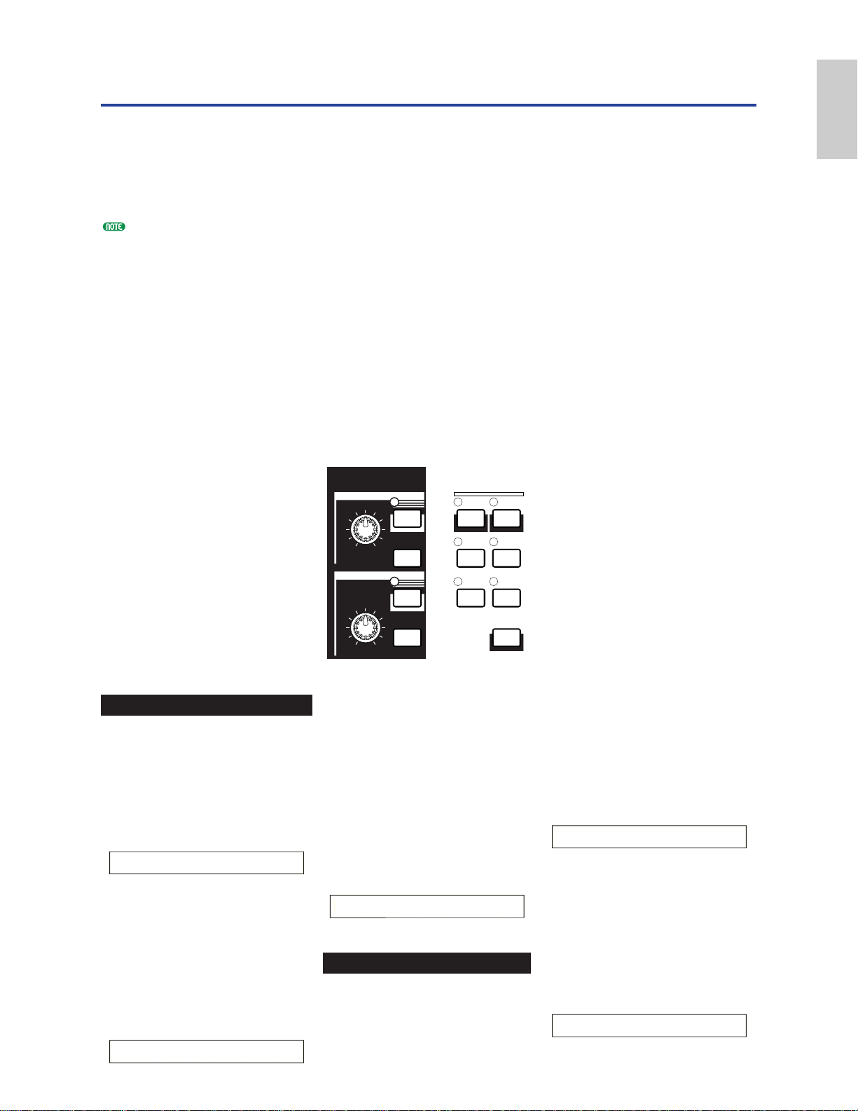
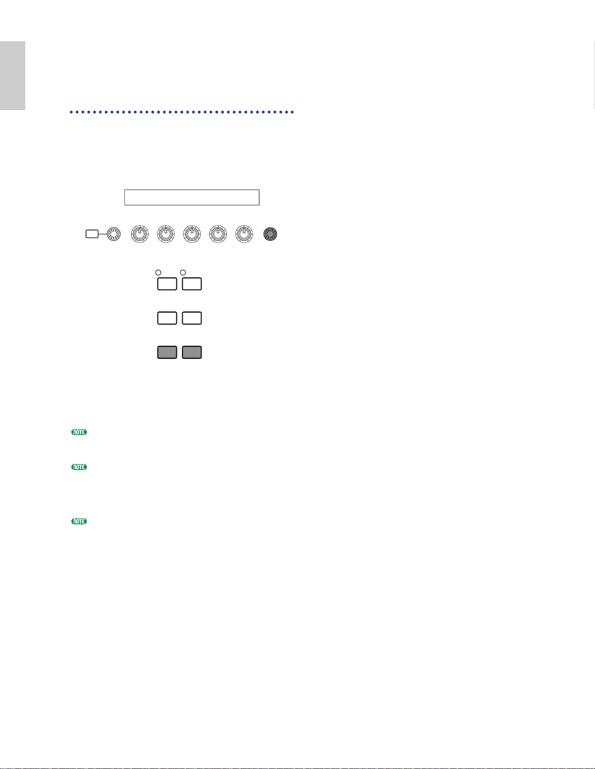
Selecting a Screen
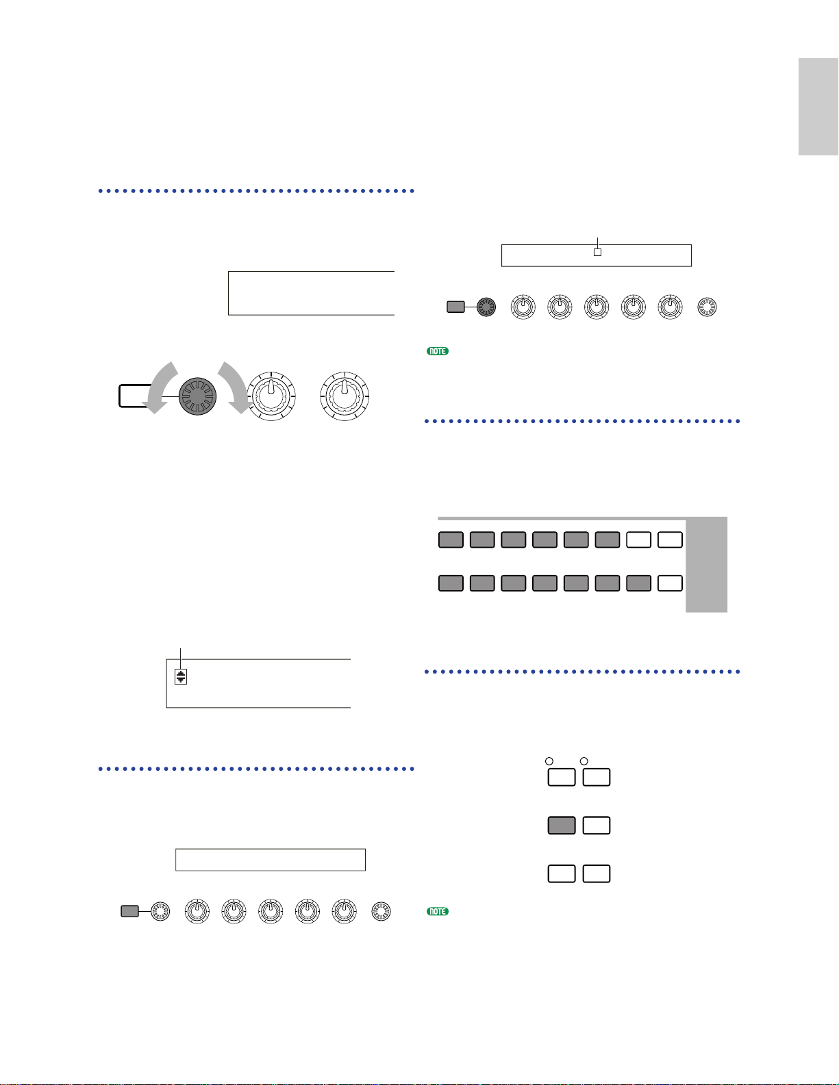
You can switch between screens using the [PAGE]
knob and pressing [SHIFT], PROGRAM/PART,
[EXIT] and [ENTER] keys.
[PAGE] Knob
Usually, there are several screens and sub-screens
in each Mode. Use the [PAGE] knob to switch
between screens.
As shown below, the “¥” indicator is displayed to
the left of the screen if there are more screens
before and after that which you are currently
viewing.
At the first in a series of screens, you will see the
“∂” indicator meaning that there are more screens
to follow, but none before it. At the last screen,
you will see the “µ” indicator meaning that there
are no more screens to follow.
[SHIFT] Key
If you hold down the [SHIFT] key in Voice Play
Mode, you can modify the parameters on screen
as follows.
SHIFT PAGE
PART
/
ELEMENT
DATAA B C 1 2
(Oct= +3) PRE1:128(H16) [Pf:GrandPiano]
(Tch= 1)
LFO Depth)
EL1234
Indicator
SHIFT PAGE A B
VCE Srch) PRE1:
Memory
Next screenPrevious screen
Some Modes have more screens. In this case, you
can use the [PAGE] knob while holding down the
[SHIFT] key to switch to a specific screen.
For example, if you use the [PAGE] knob while
holding down the [SHIFT] key in Voice Edit
Mode, the following screen is shown. Select a
specific item using the cursor (≥), then release the
[SHIFT] key to switch to the parameter screen for
that item.
The [SHIFT] key also has other functions, as
described in other sections in this manual.
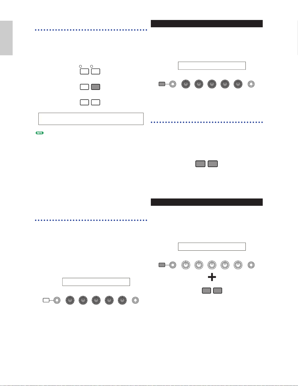
PROGRAM/PART keys
With the CS6x, in Voice Edit Mode,
PROGRAM/PART keys can be used to select the
items shown under the keys and to switch to their
screens.
[EXIT] Key
Press the [EXIT] key to move up (exit) in the
hierarchical structure and return to the previous
screen.
The [EXIT] key also has other more functions, as
described in other sections in this manual.
Cursor
GENíOther) Com:>GEN≥QED> ARP>CTL>LFO>EFF
EL1234 Elem:>OSC>PCH> FLT>AMP>LFO>EQ
SHIFT PAGE
PART
/
ELEMENT
DATAA B C 1 2
1 2 3 4 5 6 7 8
GENERAL QED ARPEGGIO CONTROL COM LFO EFFECT
9 10 11 12 13 14 15 16
OSC PITCH FILTER AMPLITUDE LFO EQ PLG
PROGRAM
PART
EF
MASTER
KEYBOARD
BYPASS
EXIT ENTER
DEC/NO INC/YES
Page 24
24
Basics
Section
[ENTER] Key
Normally, the [ENTER] key is used to apply
parameter settings. In some cases, however, the
following screen appears prompting you to press
the [ENTER] key.
The [ENTER] key has other functions, as described
in other sections in this manual.
Entering Data
You can use the knobs to directly alter their
respective parameters on the screen.
Alternatively, you can also move the cursor (≥) to
a parameter and set its value using the
[INC/YES] and [DEC/NO] keys, or the [DATA]
knob.
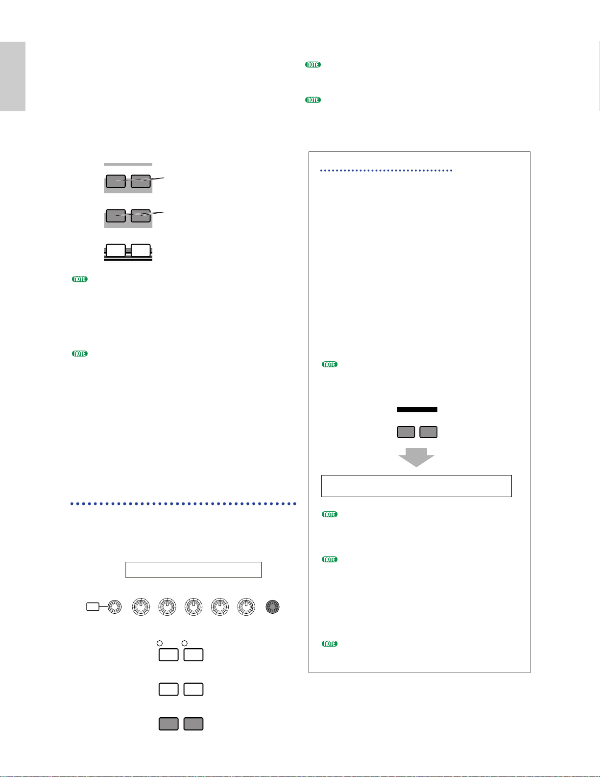
Knobs [A], [B], [C], [1]
and [2]
Each parameter in a screen is normally associated
with a knob ([A], [B], [C], [1] or [2]) below the
display. When you use one of these knobs, the
cursor (≥) moves to its respective parameter and
you can change its value. For instance, you can use
Knob [B] at the following screen to change the
Level setting. Turn the knob clockwise to increase
the value and anti-clockwise to decrease it.
SHIFT PAGE
PART
/
ELEMENT
DATAA B C 1 2
OSCíOut) Level Delay InsEF
EL1234 ≥ 96 0 ins2
Moving the Cursor
By using a knob ([A], [B], [C], [1] or [2]) while
holding down the [SHIFT] key, you can move the
cursor (≥) to the respective parameter on the
screen without affecting its value.
[INC/YES] and [DEC/NO]
Keys
You can use the [INC/YES] key to increment a
parameter setting by one step, or the [DEC/NO]
key to decrement it. If you hold down either key,
the value is continuously changed.
You can also use these keys to answer “YES” or
“NO” when a confirmation message is displayed.
Moving the Cursor
By pressing the [INC/YES] or [DEC/NO] key
while holding down the [SHIFT] key, you can
move the cursor between parameters on the
screen without affecting their values.
SHIFT PAGE
PART
/
ELEMENT
DATAA B C 1 2
OSCíOut) Level Delay InsEF
EL1234 ≥ 96 0 ins2
DEC/NO INC/YES
DEC/NO INC/YES
SHIFT PAGE
PART
/
ELEMENT
DATAA B C 1 2
OSCíOut) Level Delay InsEF
EL1234 96 ≥ 0 ins2
EF
MASTER
BYPASS
KEYBOARD
EXIT ENTER
DEC/NO INC/YES
EFFíEF1) Ctgry Type [ENTER]
C 1234 MOD Tremolo to Edit
Page 25
25
Basics
Section
[DATA] Knob
Use this knob to change the value of the
parameter at which the cursor is positioned.
Turn the knob clockwise to increment the value
one click (step) at a time, or turn it anti-clockwise
decrement it.
Moving the Cursor
Turn the [DATA] knob clockwise or anticlockwise while holding down the [SHIFT] key to
move the cursor to a parameter in the screen
without affecting its value.
[ENTER] Key
Use this key to apply a setting (when it is
blinking, for example). The [ENTER] key is also
used when executing a Job or Store operation, as
described in other sections of this manual.
DEC/NO INC/YES
EXIT ENTER
EF
BYPASS
MASTER
KEYBOARD
SHIFT PAGE
PART
/
ELEMENT
DATAA B C 1 2
OSCíOut) Level Delay InsEF
EL1234 ≥ 96 0 ins2
SHIFT PAGE
PART
/
ELEMENT
DATAA B C 1 2
OSCíOut) Level Delay InsEF
EL1234 ≥ 96 0 ins2
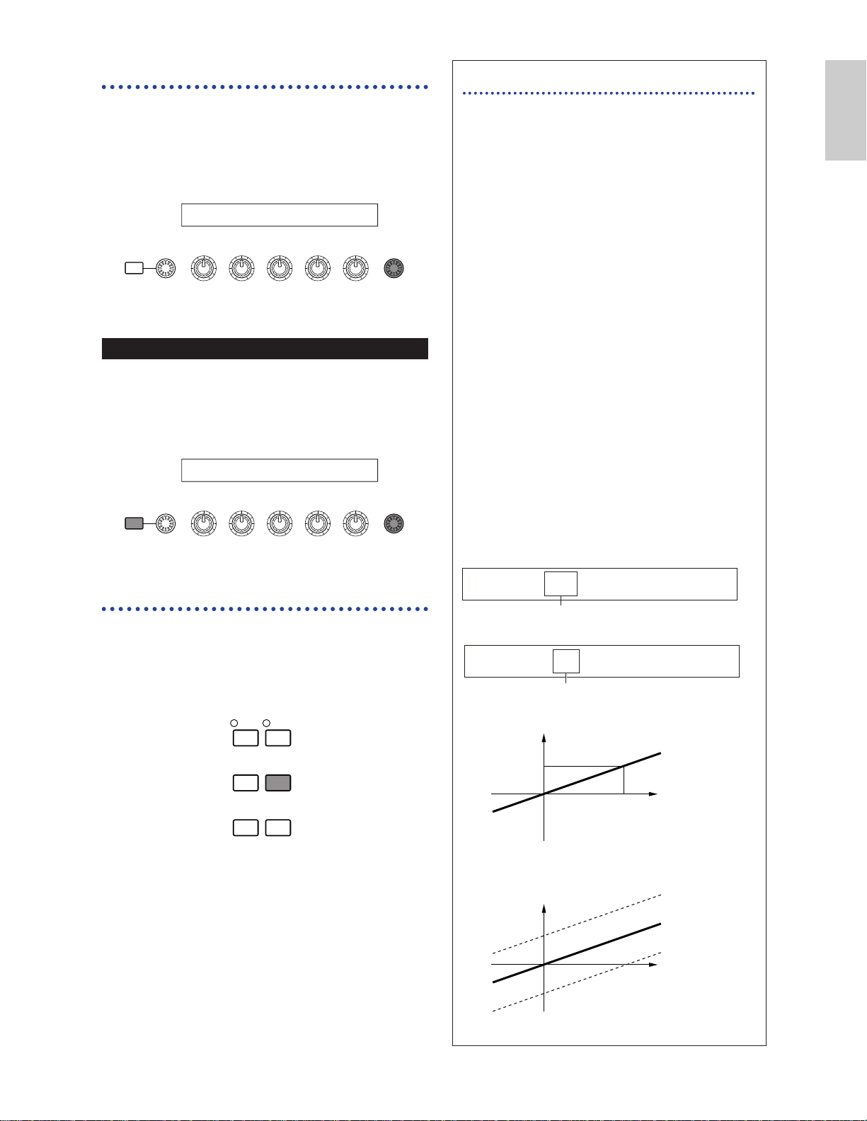
Types of Parameters (Absolute and Relative)
There are many ways to set parameters. Some
parameters require you to directly enter
numerical settings or alphabetic characters.
With others, you can choose from a number of
available settings. Furthermore, some types of
parameters are “absolute” whereas others are
“relative.”
For example, the absolute parameter in the
following illustration can be set to either
“mono” or “poly.” For other absolute
parameters such as Volume, the setting can be
any value between zero and 127. The Volume
setting has a linear, one-to-one relationship
with the actual volume, as shown in the graph
on the left.
However, relative parameters do not follow the
same relationship. The graph on the bottom
shows the role of the Velocity Offset
parameter. The value you have set here,
known as an “offset,” is added to, or
subtracted from, the actual value. With
Velocity Offset, the specified offset value is
added to, or subtracted from, the actual
velocity of the notes you play on the keyboard.
Sometimes, these types of relative parameters
are set as a percentage.
127
Volume
1 Volume (absolute)
0
Volume
offset added -10
Actual velocity
offset added +10
2 Velocity offset (relative)
0
-64
Offset
+64
QEDíLevel) Vol Pan RevSend ChoSend
C 1234 127 C 127 127
0~127
GEN Other) Mode Assign MicroTuning
C 1234 poly single 31:Indian
mono/poly
Page 26
26
Basics
Section
Demo Playback
Several demo songs are supplied with this synthesizer. You can play them back as follows.
Make sure synthesizer is ready for playback. Details are given in the section “Before Use” on Page 12.
At the “SEQ Demo” screen, any data in the instrument’s internal memory (System, Internal Voices, Phrase Clip
or the like) will be overwritten by the data for the demo song. Important data should be saved to Memory Card
(Page 171) beforehand.
There are other demo song files provided on the included Memory Card. You can play them back in a normal
Sequence Play operation after you load “all” data file from the Card (Page 174). Refer to page 162 for details.
1Press the SEQ PLAY key to enter Sequence Play Mode. You will see the following screen.
There are two screens in Sequence Play Mode. Use the [PAGE] knob to switch to the screen shown above.
2Press the [INC/YES] key to enter the SEQ Demo screen.
To cancel demo playback, press the [DEC/NO] key.
3Press the [PLAY/STOP] key to start playback of the song.
4Press the [PLAY/STOP] key again to stop playback.
At the end of the song, playback is automatically looped back to the beginning.
You can change the playback tempo using the [TEMPO] knob or Knob [C]. To use the song’s original tempo,
select a tempo value of “***.”
Details about Sequence Play Mode (and demo playback from Memory Card), are given on Page 161.
SEQ Demo)<< Are you sure? [YES]/[NO] >>
System,IntVoice,PClip will be changed.
Demo song name
SEQ Demo) Song:[DEMOSONG]
≥ 001 ⁄= 120
Demo song number Playback tempo
Page 27
27
Basics
Section
Voices and Performances
Playing a Voice
Based on an AWM2 synthesis engine, this synthesizer offers various kinds of preset Voices (256
Normal Voices and 8 Drum Voices). You can also create your original Voices and store them into the
instrument’s internal memory (INT) or an external Memory Card (EXT). The internal and external
memory can each contain up to 128 Normal Voices and 2 Drum Voices. You can freely select and play
Voices from both groups of memories, as explained in the following.
DEC/NO INC/YES
EXIT ENTER
EF
BYPASS
MASTER
KEYBOARD
MEMORY
PRE1
INT
DRUM
EXT
PLG1 PLG2
PRE2
DRUM
VOICE PERFORM
UTILITY CARD
EDIT
COMPARE
JOB
STORE
MODE
VCE Play) PRE1:128(H16)[Pf: GrandPiano]
EQ Low EQ Mid EQ Hi Cut off RevTime
CURSOR
SHIFT PAGE PART
/
ELEMENT DATA
SYSTEM A B C 1 2
1 [VOICE] key 2 MEMORY key3 [DEC/NO]
and
[INC/YES]
keys
3 [DATA] knob
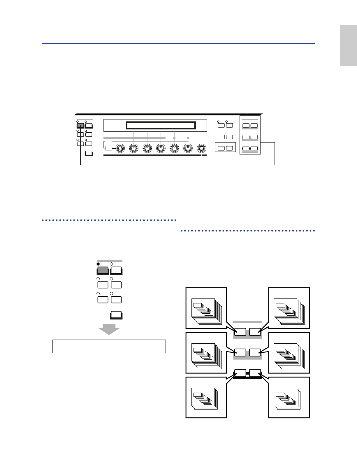
1 Press the [VOICE] key
The [VOICE] key LED will light, showing that
you are now in Voice Play Mode. The following
appears in the display.
At this point, you can play the Voice (named on
the screen) via keyboard.
VCE Play) PRE1:001(A01)[Sq:Generation]
EQLow-G EQMid-G EQHi-G FLT-Rez HPF
VOICE PERFORM
UTILITY CARD
EDIT
COMPARE
JOB
STORE
MODE
2 Press a MEMORY key
to select a Voice Memory
There are six Voice Memories: PRE1 (Preset 1),
PRE2 (Preset 2), INT (Internal), EXT (External),
PLG1 (Plug-in 1), and PLG2 (Plug-in 2). Within
each Voice Memory are several Banks (up to
eight, A to H) in which the Voices are stored.
The following illustration shows how Voices are
stored in a Voice Memory.
PRE2 (Preset 2)
Bank A~H
1~16
Voice
EXT (External)
Bank A~H
1~16
Voice
PRE1 (Preset 1)
Bank A~H
1~16
Voice
INT (Internal)
Bank A~H
1~16
Voice
PLG1 (Plug-in 1)
Bank A~D
1~16
Voice
PLG2 (Plug-in 2)
Bank A~D
1~16
Voice
MEMORY
PRE1
INT
DRUM
EXT
PLG1 PLG2
PRE2
DRUM
Page 28
Now you can play a selected Voice when you play
the keyboard on the CS6x or the external
keyboard connected to the CS6R. Try auditioning
other Voices.
Details about selecting Voices using the [DATA]
knob or the [DEC/NO] and [INC/YES] keys are
given on Page 76.
You can also select Voices using a combination of
BANK and PROGRAM/PART keys (CS6x), or using
the Category Search feature. Details about selecting
Voices are given on Page 75.
Octave Shifting (CS6x only)
If you need to raise or lower the keyboard note
range for the Voice, you can use the OCTAVE
[UP] key to raise the range by an octave and
the OCTAVE [DOWN] key to lower it by an
octave. You can shift the note range by up to
three octaves in either direction. The current
octave setting is shown in the left corner of the
display while the OCTAVE [UP] or [DOWN]
key is being held down.
For instance, if you press the OCTAVE [UP]
key twice (+2), you will actually play note C5
by pressing note C3 on the keyboard (i.e., the
note you play is shifted up two octaves). To
return to the standard octave range (0), press
the OCTAVE [UP] and [DOWN] keys
simultaneously.
You can have the current octave setting shown
in the display while holding down the [SHIFT]
key. Use this feature for confirmation.
If a note is shifted beyond G8 (MIDI note
number 127), it will automatically be shifted
to the octave below. For instance, note G#8
will be played as G#7.
OCTAVE [UP] and [DOWN] keys are linked
to the “Coarse/Fine” parameter (Page 90) in
the PCH Tune screen of Voice Edit Mode, and
also the “Oct” parameter (Page 163) in the
MSTR Kbd screen of Utility Mode. The
OCTAVE [UP] and [DOWN] keys may not
function if these parameters also have been
set to shift the range.
You can also use the OCTAVE [UP] and
[DOWN] keys in Performance Play Mode.
28
Basics
Section
The Drum Voices are held in separate areas of
each Memory, and are accessed as follows.
• To access the Preset Drum Memories
(PRE:DR1 ~ DR8):
Press the MEMORY [PRE2] key while holding
down the MEMORY [PRE1] key.
• To access the User Drum Memories
(INT:DR1/2, EXT:DR1/2):
Press the MEMORY [EXT] key while holding
down the MEMORY [INT] key.
PRE1 and PRE2 (Preset 1 and 2) are stored in internal
Read Only Memory (ROM) and contain preset Voices
which are never overwritten. INT (internal) is stored
in Random Access Memory (RAM) and contains the
factory default Voices. These can be overwritten, but
can be recalled from the original factory settings at any
time if required.
EXT (external) is stored on a Memory Card inserted
in the CARD slot. If there is no Memory Card
inserted and you attempt to select an EXT Voice, “---
--” will be displayed and no sound will be produced.
With a Memory Card inserted, you can select and
play EXT Voices. PLG1 or PLG2 Voices can only be
selected if a Plug-in Board is installed.
3 Select a Voice Number
using the [DATA] knob or
the [INC/YES] and
[DEC/NO] keys
Turn the [DATA] knob clockwise or press the
[INC/YES] key to increment the Voice Number.
Turn it anti-clockwise or press the [DEC/NO] key
to decrement the Voice Number.
DEC/NO INC/YES
EXIT ENTER
EF
BYPASS
MASTER
KEYBOARD
SHIFT PAGE
PART
/
ELEMENT
DATAA B C 1 2
VCE Play) PRE1:128(H16) [Pf:GrandPiano]
EQ Low EQ Mid EQ Hi Cutoff RevTime
MEMORY
PRE1
PRE2
DRUM
INT
EXT
DRUM
PLG1 PLG2
To access Preset Drum Voices
(PRE:DR1 ~ DR8)
To access User Drum Voices
(INT:DR1/2, EXT:DR1/2)
OCTAVE
DOWN UP
(Oct= -3) PRE1:001(A01)[Sq:Generation]
EQLow-G EQMid-G EQHi-G FLT-Rez HPF
Page 29
29
Basics
Section
Playing a Performance
In Performance Play Mode, you can select and play any of 128 internal and 64 external (Memory
Card) Performances.
A Performance is a set of Voices used with the built-in (or an external) sequencer. Performances also
let you set the synthesizer up for multitimbral operation.
Each Performance can contain up to 16 Parts assigned to different Voices, plus extra Parts for Phrase
Clip, A/D INPUT and Plug-in Boards. If the Layer Switch (Page 133) parameter is switched on for
any Parts, those Parts can be play in unison. Also, you can assign multiple Parts to different MIDI
channels so that they can be played or be controlled individually using the built-in (or an external)
sequencer. Up to 128 Performances can be stored in the internal memory and up to 64 on Memory
Card. These Performance settings are available in Performance Edit Mode (Page 121). Here, we will
show how to get started with Performance Play after selecting a Performance.
DEC/NO INC/YES
EXIT ENTER
EF
BYPASS
MASTER
KEYBOARD
MEMORY
PRE1
INT
DRUM
EXT
PLG1 PLG2
PRE2
DRUM
VOICE PERFORM
UTILITY CARD
EDIT
COMPARE
JOB
STORE
MODE
PFM Play) INT:128(H16)[Pf: Init Perf ]
EQ Low EQ Mid EQ Hi Cut off RevTime
CURSOR
SHIFT PAGE PART
/
ELEMENT DATA
SYSTEM A B C 1 2
1 [PERFORM] key 2 MEMORY key3 [DEC/NO]
and
[INC/YES]
keys
3 [DATA]
knob
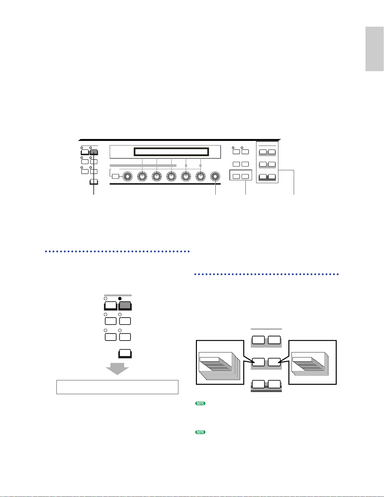
1
Press the [PERFORM] key
The [PERFORM] key LED will light, showing
that you are now in Performance Play Mode. The
following appears in the display.
At this point, you can play the Performance
(named on the screen) via keyboard.
PFM Play) INT:001(A01)[--:Init Perf ]
EQ Low EQ Mid EQ Hi -1 +0
VOICE PERFORM
UTILITY CARD
EDIT
COMPARE
JOB
STORE
MODE
2 Press a MEMORY key
to select a Performance
Memory
There are two Performance Memories: INT
(internal) and EXT (External). The INT memory
is divided into eight Banks (A to H) of 8
Performances. The EXT memory is divided into
four Banks (A to D) of 4 Performances.
INT (internal) is stored in internal Random Access
Memory (RAM) and contains factory default
Performances. These can be overwritten but can
recalled at any time.
EXT (external) is stored on a Memory Card (RAM)
inserted in the CARD slot. If there is no Memory
Card inserted and you attempt to select an EXT
Performance, “-----” will be displayed and no sound
will be produced. With a Memory Card inserted,
you can select and play EXT Performances.
MEMORY
PRE1
PRE2
INT (Internal)
Bank A~H
1~16 1~16
Performance Performance
DRUM
INT
EXT
DRUM
PLG1 PLG2
EXT (External)
Bank A~D
Page 30
30
Basics
Section
3 Select a Performance
Number using the [DATA]
knob or the [INC/YES]
and [DEC/NO] keys
Turn the [DATA] knob clockwise or press the
[INC/YES] key to increment the Performance
Number. Turn it anti-clockwise or press the
[DEC/NO] key to decrement the Performance
Number.
You can now play Parts in the Performance via
the keyboard. If the Layer Switch parameter is
switched on for any Parts, those Parts can be play
in unison. Now try selecting other Performances.
Details about selecting Performances using the
[DATA] knob or the [DEC/NO] and [INC/YES] keys
are given on Page 76.
You can also select Performances using a
combination of BANK and PROGRAM/PART keys
(CS6x), or using the Category Search feature.
Details about selecting Performances are given on
Page 119.
On selection, a Performance may take a few seconds
to become ready since the settings for multiple Parts
are applied.
PFM Play) INT:001(A01) [--:Init Perf ]
EQLow-G EQMid-G EQHi-G ------- -------
SHIFT PAGE
PART
/
ELEMENT
EF
MASTER
KEYBOARD
BYPASS
EXIT ENTER
DEC/NO INC/YES
DATAA B C 1 2
Page 31

31
Basics
Section
An Overview of the CS6x/CS6R
In this section, an overview of the many features of the CS6x/CS6R is given.
The CS6x/CS6R hardware is made up of a number of sections, as shown in the following diagram.
Controller Section
This section consists of the keyboard, Pitch Bend and Modulation Wheels, Ribbon Controller, Sound
Control Knobs, and so on. The keyboard itself doesn’t generate sounds, but instead sends note,
velocity and other information to the synthesizer’s tone generator section when you plays notes. The
controllers also send changes. Information from the keyboard and controllers can be transmitted to
other external MIDI devices through the MIDI OUT connector.
The CS6R has no keyboard, Pitch Bend or Modulation Wheels, Ribbon Controller or Sound Control Knobs.
Sequencer Section
This section can be used to play back Standard MIDI Files held on Memory Card. The contents of
Tracks 1 to 16 correspond to MIDI channels and Parts in a Performance as shown in the following
illustration. The sequencer can play back songs with a different Voice assigned to each Part.
Sequencer
Tone Generator
(Performance Parts)
Track1 Piano Ch1
Track2 Bass Ch2
Track3
Strings
Piano
Bass
Strings
Percussion
Ch3
Track16
Percussion
Ch16
Ch1
Ch2
Ch3
Ch16
Controller Section
Sequencer
Section
Song File Playback
Arpeggiator
Keyboard
(CS6x)
Tone Generator
Section
AWM2
Plug-in Board
Phrase Clip
Controllers
Effects Section
Page 32

32
Basics
Section
Tone Generator Section
This section plays back sounds according to information received from the keyboard and controllers.
The following example illustrates the path taken by the signal from an Element in Voice Mode.
About the Tone Generator
The tone generator section in the CS6x/CS6R consists of AWM2, Phrase Clip and Plug-in units.
AWM2 (Advanced Wave Memory 2) is a synthesis system based on the use of sampled waveforms,
and is used in many Yamaha synthesizers. For extra realism, each AWM2 Voice uses multiple samples
of a real instrument’s waveform. Furthermore, a wide variety of envelope generator, filter,
modulation, and other parameters can be applied to the basic waveform.
AWM2 is not just limited to general musical instruments (Normal Voices). It can also be used for setting up
percussive instruments (Drum Voices). Details about Normal and Drum Voices are given on Page 37.
Phrase Clips are sounds recorded via microphone or from external audio equipment, or sounds loaded
directly via Memory Card. These are then stored in internal RAM and can be played back as musical
sounds. They can be edited and easily set up for use as rhythm loops, percussion/drum sounds and
sound effect.
Plug-in Boards add more features to the system. When installed, they combine perfectly with the
synthesizer’s built-in tone generator section.
The following types of Plug-in Board are available, and up to two boards can be installed in the
synthesizer. These boards are not simply a source of more Voices; they are also tone generators in
their own right and extend the system-level specifications such as maximum polyphony. You can play
Plug-in Voices just like ordinary internal Voices and use them as Parts in a Performance (Page 108).
This synthesizer is compatible with the Modular Synthesis Plug-in System (see next page). There are
three types of Modular Synthesis Plug-in System-compatible Plug-in Boards: Single Part, Multi-Part
and Effect Plug-in Board. Using these, you can build your own system based on the sounds you
require.
Single Part Plug-in Boards
• Analog Physical Modeling Plug-in Board (PLG150-AN)
Using Analog Physical Modeling (AN) synthesis, the very latest digital technology is used to
accurately reproduce the sound of analog synthesizers. With this board installed, you have realtime control over the playback of vintage synthesizer sounds as well as the very latest sounds heard
in today’s club-oriented music.
• Piano Plug-in Board (PLG150-PF)
A massive 16MB of waveform memory is dedicated to the reproduction of piano sounds using
AWM2 synthesis. This board offers 136 stereo sounds, including a number of acoustic and electric
pianos, and up to 64-note polyphony. You can even install two of these boards to double the
polyphony to 128 notes.
Tone Generator Section
OSC
(Oscillator)
Outputs the
waveform of
each Element.
Each Voice
consists of up to
four Elements.
Controls the
pitch of each
Element output
from OSC.
FILTERPITCH
Changes the
tonal quality of
each Element
output from
PITCH.
AMP
(Amplitude)
Controls the
output level
(amplitude) of
each Element
output from
FILTER. The
signals are then
sent at this level
to the Effects
Units.
To Effects Units
Page 33
33
Basics
Section
• Advanced DX/TX Plug-in Board (PLG150-DX)
The sounds of the DX7 are available on this Plug-in Board. Unlike with PCM-based solutions, this
does not use sampled waveforms. Instead, it uses the actual FM sound generator engine of the DXseries synthesizers to give a completely faithful reproduction. Sounds are compatible with those of
the DX7, and the board can even receive DX7 data via MIDI bulk dump.
• Virtual Acoustic Plug-in Board (PLG150-VL)
With Virtual Acoustic (VA) synthesis, the sounds of real instruments are modeled (simulated) in
real time, giving a degree of realism that cannot be achieved using conventional PCM-based
synthesis techniques. When playing these sounds using an optional Breath Controller (BC3) or
MIDI Wind Controller (WX5), you can even capture some of the physical feel of woodwind
instruments.
Effect Plug-in Boards
• Vocal Harmony Plug-in Board (PLG100-VH)
With this board installed, you can add harmonies to selected parts using four types of effects.
Chorus parts for vocals can be created automatically from chords that have been prepared and
stored as MIDI data. You can also use the synthesizer like a vocoder by connecting and using a
microphone while playing the keyboard.
Multi-Part Plug-in Board
• XG Plug-in Board (PLG100-XG)
This Plug-in Board is a 16-part XG sound generator. You can play back XG/GM song files using the
rich variety of sounds and effects on this board.
More Plug-in Boards will be available in future.
About MODULAR SYNTHESIS PLUG-IN SYSTEM
The Yamaha Modular Synthesis Plug-in System offers powerful expansion and upgrade capabilities
for Modular Synthesis-Plug-in-compatible synthesizers, tone generators and sound cards. This
enables you to easily and effectively take advantage of the latest and most sophisticated synthesizer
and effects technology, allowing you to keep pace with the rapid and multi-faceted advances in
modern music production.
Maximum Polyphony
The maximum sonic polyphony is 64 for AWM2 (the figure includes Phrase Clips), plus the
polyphony of the Plug-in Board (if installed). The actual note polyphony will vary depending on the
type of tone generator unit used, the number of Elements in the Voice, and the note polyphony of the
Plug-in Board.
In the case of AWM2 Voices, the polyphony figure of 64 is divided by the number of Elements in the
Voice. For instance, if a Voice consists of two Elements, the maximum note polyphony for the Voice is
32.
Page 34

34
Basics
Section
Effects Section
The effects can be used to change the sound of a Voice or Performance. There are two Insertion
Effect Units plus a Reverb Unit (with 12 types of reverb) and a Chorus Unit (with 23 types of
chorus). Each of the Insertion Effect units offers a variety of effects, and the units themselves can be
connected in parallel or in series.
In Voice/Performance Mode, different Effects settings can be assigned to each Voice/Performance,
though the way they are connected (series or parallel) varies slightly. As shown in the following
illustration, the two Insertion Effect units can be independently switched on or off for each Element
in a Voice. So basically, the Insertion Effects can be set on a per Element basis. After being passed
through the Insertion Effects, the signals from all individual Elements are mixed and sent to the
Reverb and Chorus Units. These Reverb and Chorus Units apply effects to the sound as a whole
before it is sent to the outputs, and are therefore known as System Effects.
In Performance Mode, the Insertion Effects can be set for two Parts: a Voice, Phrase Clip or A/D Input
Part, plus a Plug-in Part. However, the System Effects (Reverb and Chorus) are not applied to Parts,
but to the Performance as a whole.
Details about Effects are given on Page 65.
Voice Mode Performance Mode
Output
Element
1~4
Insertion
Effects
1
2
System Effects
Reverb
Chorus
Output
Output
Voice1~16
Element
1~4
Phrase Clip
Insertion
Effects
1/2
1
2
System Effects
Reverb
Chorus
A/D Part
Plug-in 1/2 Board
Insertion
Effects
1
Page 35

35
Basics
Section
About the Modes
The CS6x/CS6R has various Modes which you can select according to the task you wish to perform.
VOICE PERFORM
UTILITY CARD
EDIT
COMPARE
JOB
STORE
MODE
PLAY
/
STOP
REC
PHRASE CLIP
SEQ PLAY
PITCH
TEMPO
Performance Mode
Performance Play Mode
Performance Edit Mode
Performance Job Mode
Utility Job Mode
Card Mode
Utility Mode
Sequence Play Mode
Voice Mode
Voice Play Mode
Voice Edit Mode
Voice Job Mode
Phrase Clip Mode
Phrase Clip Play Mode
Phrase Clip Record Mode
Phrase Clip Edit Mode
Phrase Clip Job Mode
Voice Mode (Page 74)
Voice Play Mode
Normal Voices and Drum Voices
can be played in this Mode. You
can select from Preset Voices
(256 Normal Voices plus 8
Drum Kits), Internal (User)
Voices (128 Normal Voices plus
2 Drum Kits) and External
(Memory Card) Voices (128
Normal Voices plus 2 Drum
Kits). That is a choice of 512
Normal Voices and 12 Drum
Kits. The choice is extended
further still if you have an
optional Plug-in Board installed.
The MIDI settings for Voices are
set in Utility Mode.
Voice Edit Mode
Normal Voices and Drum Voices
can be created and edited in this
Mode. You can save up to 128
edited Normal Voices and 2
edited Drum Kits as User Voices
in internal memory. You can
also store them to Memory Card
as external memory.
Voice Job Mode
In this Mode, you can copy and
initialize Voices, and perform
other such operations (Jobs) on
them.
Performance Mode (Page 117)
Performance Play Mode
This Mode is used when
playing Performances. You can
layer multiple Voices (Parts) to
create rich sonic textures. You
can also create multitimbral
setups by assigning Parts to
different MIDI channels. You
can layer A/D Input, Phrase
Clip and Plug-in Parts, as well
as AWM2-based Voices.
Performance Edit Mode
In this Mode, you can edit and
create Performances. You can
save up to 128 Performances to
internal memory or up to 64 to
external memory (Memory Card).
Performance Job Mode
In this Mode, you can copy
and initialize Performances,
and perform other such
operations (Jobs) on them.
Phrase Clip Mode (Page 142)
Phrase Clip Play Mode
In this Mode, you can select
and play Phrase Clips.
Phrase Clip Record Mode
You can record sounds into the
synthesizer from a microphone or
other audio source in this Mode.
These sounds (Phrase Clips) can
then be played back in real time via
keyboard. Furthermore, Phrase
Clips that you have already
recorded can be re-recorded as new
Phrase Clips after having, say,
Chorus effects applied to them.
Phrase Clip Edit Mode
This Mode is used for editing
Phrase Clips. Once you have
recorded the Phrase Clips, you
need to edit them to set their
loop points and other
parameters. You can also create
Clip Kits by assigning them to
notes on the keyboard.
Phrase Clip Job Mode
In this Mode, you can copy and
delete Phrase Clips, and perform
other such operations (Jobs) on
them.
Sequence Play Mode (Page 161)
In this Mode, you can use the
sequencer to play back Song files
(Standard MIDI Files) held on
Memory Card. The Songs can be
played back individually or as a
chain. By switching Performance,
you can also change the sounds
associated with each track in a Song.
Utility Mode (Page 163)
Select this Mode when setting
parameters that apply to the
synthesizer system as a whole.
These include MIDI settings and
synthesizer setup parameters.
Utility Job Mode
In this Mode, you can restore the
synthesizer’s factory settings.
Card Mode (Page 171)
Insert a Memory Card into the
CARD slot and you can save
files to it, load files from it, and
do various other things with the
data on the card.
Page 36

36
Basics
Section
Voices
A Voice is a sound created from the many parameters set in the synthesizer. In Voice Play Mode, you
can select and play any of these Voices. In Performance Play Mode, several different Voices (known as
Parts in this Mode) can be layered and played simultaneously via keyboard or a sequencer. Four
groups of Voices are available (Preset 1, Preset 2, Internal and External). Up to two further groups of
Voices are available if optional Plug-in Boards have been installed.
1~16
Voice
1~16
Voice
1~16
Voice
1~16
Voice
1~16
Voice
Preset1
(128 Preset Voices)
Banks A~H
Preset2
(128 Preset Voices)
Banks A~H
Internal
(128 User Voice)
Banks A~H
External
(128 User Voice)
Banks A~H
(2 User Drum
Voices)
(2 User Drum
Voices)
256 Normal +
8 Drum Voice (Preset)
Controllers
Controllers Sequencer
Song play
Tone Generator
Voice
Tone Generator
Performance
Playing a Voice Playing a Performance
Clip Kits 1~4
Clip Key
C0
~
C6
Plug-in1
(64 Plug-in Voice)
Banks A~D
1~16
Voice
Plug-in2
(64 Plug-in Voice)
Banks A~D
Plug-in
Performance Play Mode
Voice Play Mode
Part
Voice
1
PRE1:
(A01)
2
PRE1:
(A02)
3
PRE1:
(A03)
4
PRE2:
(A01)
5
PRE2:
(A02)
6
PRE2:
(A03)
7
INT:
(A01)
8
EXT:
(A01)
16
PRE1:
(A16)
Phrase
Clip
CLip
kit1
A/D
Part
Mic
etc.
Plug-in
Part 1
1
Plug-in
Part 2
2
Phrase Clip
Preset
(8 Preset Voices)
DR 1~8
Drum
Voice
256 Normal +
8 Drum Voice (User)
Page 37

37
Basics
Section
An Overview of Voices/Waves
Each Voice consists of up of up to four Elements. Each Element itself uses a high-quality waveform.
Internally, there are two Voice Types: Normal Voices and Drum Voices. Normal Voices are mainly
musical instrument-type sounds that can be played over the range of the keyboard. Drum Voices are
mainly percussion/drum sounds that are assigned to individual notes on the keyboard. A collection of
Drum Voice assignments is known as a Drum Kit.
If you have installed an optional Plug-in Board, there will be more Voices for you to choose from.
These Voices are known as Plug-in Voices, and will vary depending on the Plug-in Board you have
installed (Page 32).
The Note Limit settings (Page 90) will also affect the allocation of sounds. But basically, Normal
Voices (of up to four Elements) are playable across the whole keyboard range whereas with Drum
Voices, any of 73 different Waves can be assigned to each Drum Key on the keyboard.
A total of eight Drum Voices (DR1 to DR8) are available as presets. You can also create your own Drum Voices
and save them to internal (User) memory or to external memory (Memory Card), just as with Normal Voices.
Voice
Element 1~4
Element
Wave form
AWM2: 479 Preset waveforms
Normal Voice Drum Voice
Voice
Element 1~4
wave 1 wave 2 wave 3 wave 4 wave 5 wave 73
Page 38

38
Basics
Section
Waves
Waves are waveforms used as Elements that make up a Voice. 479 high quality preset Waves are
available. As shown in the following illustration, when creating a Voice, you can select the Wave to be
used as an Element and then set its level, pitch, tone and other parameters.
Another feature of the CS6x/CS6R is its ability to accept computer WAV/AIFF files and record real
instruments, which you can then play back as musical instrument sounds. These types of sounds are
known as Phrase Clips. You can record Waves through the microphone or line level jacks, and you
can load Waves saved on Memory Card. The Waves can then be processed in Phrase Clip Edit Mode
and assigned to notes (Clip Keys) on the keyboard to form a Clip Kit. Up to four Clip Kits can be held
in memory. You can play these Clip Kits via the keyboard or you can assign them as Parts in a
Performance.
The Clip Kit settings will be lost when you switch off your synthesizer. To avoid this situation, you should save
your Clip Kit settings to Memory Card.
wave 1~479
Element1
Element2
Element3
Element4
C-2 G8
Voice
CD
Microphone
Memory Card
Up to 256 Clips
Clip Kit 1~4
C0 C6
Save
Memory Card
Page 39

39
Basics
Section
Performances
A Performance consists of up to 20 Parts, each of which can a Normal Voice, Drum Voice, Phrase Clip,
A/D Input Part or Plug-in 1/2 Part. By switching on the Layer Switch parameter for different Parts
(up to four), you can play back rich layered sounds in Performance Play Mode. You can also create
splits so that different Parts are assigned to different areas of the keyboard. If you assign a different
MIDI channel number to each Part, each track of a sequencer can play back a different Part.
In Performance Mode, several different Voices (Parts) can be layered to create rich textures. However, this can
cause note response to become slower under some circumstances.
Performance
Song
Sequencer
MIDI CH
1~16
Part 1~16, Phrase Clip, A/D INPUT Part,
Part 1~16, Phrase Clip, A/D INPUT Part,
Plug-in 1/2 Part
Multiple
Layered Voices
Layer Switch set to “on”
Performance
Plug-in 1/2 Part
CH1
Different Voice
For Each Part
CH16
Page 40

40
Basics
Section
Easy Real-time Editing
Sound Control Knobs (CS6x only)
The Sound Control knobs allow you for on-the-fly alteration of the tonal characteristics and effects
applied to the Voice or Part of a Performance that is currently selected. The functions of each of the
knobs are explained here. The altered Voices or Performances can be stored anytime as Scene 1 or
Scene 2 (Page 45). When saving each Voice or Performance (Pages 116, 141), its Scene information is
also included. However, only the states of the two FILTER knobs, the ATTACK and DECAY knobs
and Assignable Knobs [1] and [2] are stored with each Scene.
A preset of suitable parameter settings is assigned to each sound. By using each knob, you are in effect adjusting
these settings by a certain amount. If these parameters are already preset at their minimum or maximum
settings, the settings cannot be exceeded.
The functions assigned to each of these knobs are the same as those set in the Common Quick Edit Envelope
Generator screens in Voice Edit (Page 78) and Performance Edit (Page 121).
FILTER Knobs
These two knobs let you directly adjust
filter parameters to control the tonal
characteristics of the sound. Generally,
filters are used to pass certain frequencies
of a sound and block others.
n The characteristics of the filter will vary
depending on the Filter Type parameter
setting for each Element of the Voice.
[CUTOFF] Knob
Use this knob to increase/decrease
the filter cutoff frequency. Turn the
knob clockwise to decrease the cutoff
frequency, which will produce a
brighter sound. Turn it anti-clockwise
to increase the cutoff frequency, which
has the effect of muffling the sound.
[ATTACK] Knob
Use this knob to extend/shorten the
Attack time, which is the time taken
for the sound to reach its peak level
from the moment a note is played on
the keyboard. Turn the knob
clockwise to extend the Attack time
and anti-clockwise to shorten it.
[DECAY] Knob
Use this knob to extend/shorten the
Decay time, which is the time taken
for the sound to drop from its peak
level to a steady, continuous level.
Turn the knob clockwise to extend the
Decay time and anti-clockwise to
shorten it.
[RESONANCE] Knob
Use this knob to increase/decrease
the harmonic boost applied to the
sound around the cutoff frequency.
Turn the knob clockwise to increase
the boost and anti-clockwise to
decrease it. You can give a unique
characteristic to the sound by
adjusting this parameter.
Level
Cutoff Frequency
FILTER EFFECT
EG
[SUSTAIN] Knob
Use this knob to increase/decrease
the Sustain level, which is the level of
the sound maintained while the note
is being held down. Turn the knob
clockwise to increase the Sustain
level and anti-clockwise to decrease
it.
Resonance
Frequency
CUTOFF RESONANCE
ATTACK DECAY SUSTAIN RELEASE
EFFECT Knobs
These two knobs let you directly set the
amount of reverb and chorus applied to the
sound.
[REVERB] Knob
Use this knob to increase/decrease
the Reverb Send level, which is the
amount of reverb applied to the
sound. Turn the knob clockwise to
increase the level and anti-clockwise
to decrease it.
n The effect of changing this parameter
will vary depending on the Reverb
Type parameter setting (Page 89).
The “í” indicator
When you move a knob, the í indicator is displayed to
the left of the LCD. The indicator for the Voice or
Performance remains displayed until you save your
edits. If you need to keep your edited data, you should
REVERB CHORUS
save it (Pages 116, 141).
GENíName) Ctgry
EG (Envelope Generator) Knobs
[RELEASE] Knob
Use this knob to extend/shorten the
Release time, which is the time taken
for the sound level to fade to zero
after the note has been released.
Turn the knob clockwise to extend the
Release time and anti-clockwise to
shorten it.
[CHORUS] Knob
Use this knob to increase/decrease
the Chorus Send level, which is the
amount of chorus applied to the
sound. Turn the knob clockwise to
increase the level and anti-clockwise
to decrease it.
n The effect of changing this parameter
will vary depending on the Chorus
Type parameter setting (Page 89).
Edit indicator
These four knobs let you directly control the
“envelope” of the sound. Envelopes define the
transitions in sound level from the moment you
press a note on the keyboard to the moment the
sound level fades out after you release the
note. All instruments have their own definitive
and varied envelopes, which can be simulated
using these four parameters.
Level
Sustain
Level
Attack
Decay
Time
Time
Key on Key off
Release
Time
Time
Page 41

41
Basics
Section
Ideal for Playing Live
Many features of this synthesizer make it ideal for live performances. These features are explained here.
The parameters for these features can be stored per Voice/Performance/Phrase Clip.
2
Using the Scene (CS6x) Controls (Page
2
1 Using the Arpeggiator (Page 42)
1
A wide variety of arpeggio patterns can be
created automatically by just holding down a
set of notes on the keyboard. You can specify
the sound and the note range within which the
arpeggiator is active, then use your left hand to
hold down the notes being arpeggiated while
using your right hand to play a melody line.
CS6x
Rear Panel
45)
Using the Sound Control knobs, you can
edit sounds with ease. You can then
assign two of these edits as Scenes,
then switch between them or create a
mix of the two in real time using the
SCENE [1] or [2] keys and [CONTROL]
knob on the front panel, or even a Foot
3 Using the Controllers (Page 47)
3
The Pitch Bend Wheel, Modulation Wheel
POWER
can be freely assigned to control various
sound parameters in real time. By
connecting an optional Foot Controller or
Foot Switch, you can also use your feet to
control parameters, to change Program
Number, and so on (Page 52). Also, you
can assign parameters to Knobs [A], [B],
[C], [1] and [2] on the front panel below the
LCD.
CS6R
5 Other Features (Page 59)
4 Using Phrase Clips (Page 53)
4
Existing Phrase Clips (waveform data) can be read or you
can create your own Phrase Clips by recording from external
audio sources, such as CD players.
Rhythm loops and breakbeats can easily be created. Assign
a variety of Phrase Clips to notes on the keyboard to form a
Clip Kit (of which you can create up to four). Then play this
Clip Kit live or assign it to a Part in a Performance for
playback using a sequencer.
5
In addition to the Sound Control knobs, there is
also a knob and an [ON/OFF] key for
Portamento. These conveniently let you
switch Portamento on or off and adjust the
Portamento time in real time (CS6x).
Page 42
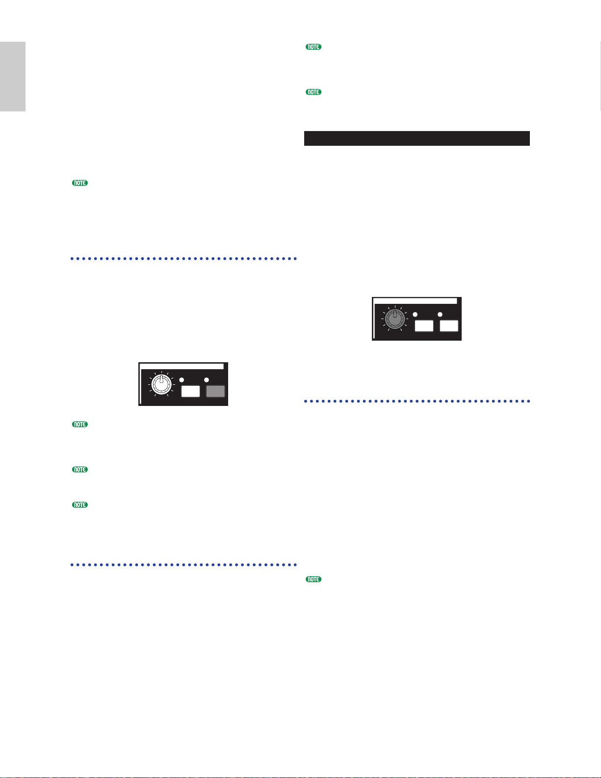
42
Basics
Section
1 Arpeggiator
The arpeggiator is particularly suited to
dance/techno music genres. You can assign any
of 128 Arpeggio Types to each Voice, Performance
or Clip Kit, and adjust the tempo. You can also
set the Arpeggio Mode (the way in which the
arpeggio is played back when you press a note)
and Play Effects to create your own original
grooves. Arpeggio information can be transmitted
through the MIDI Out.
On the CS6R, the Arpeggiator's ON/OFF, GATE
TIME, and HOLD functions are set in the relevant
Edit Modes (Pages 82, 83).
Switching the
Arpeggiator On/Off
The arpeggiator can be used in Voice,
Performance or Phrase Clip Mode, and also when
the sequencer is being used. You can switch the
arpeggiator on/off using the ARPEGGIO
[ON/OFF] key on the front panel. When
switched on, the ARPEGGIO [ON/OFF] key LED
will be lit.
If the arpeggiator is already switched on and ready
for use, the ARPEGGIO [ON/OFF] key LED will
light when you select the Voice, Performance or Clip
Kit.
The on/off state of the arpeggiator is stored with
each Voice, Performance or Clip Kit. (Pages 116, 141,
160)
You can check/change the Arpeggio Type, Tempo
and other parameters in the Arp screen (Page 82) in
Voice, Performance or Phrase Clip Edit Mode.
Using the Arpeggiator
When the arpeggiator is switched on, the notes
you play (and hold down) on the keyboard will be
arpeggiated using the currently selected Voice,
Performance or Clip Kit, and according to the
Arpeggio Type, Tempo and Note Limit settings.
In Voice Mode, the currently selected Voice will be
arpeggiated.
In Performance Mode, the Voices of Parts for
which both the Layer and Arpeggiator are
switched on, are arpeggiated (Page 133).
In Phrase Clip Mode, the currently selected Clip
Kit (the Phrase Clips assigned to the notes you
play) will be arpeggiated.
Only notes within the Note Limit range will be
arpeggiated. Therefore, if the notes you play are not
arpeggiated, they may be outside this range. Details
about the Note Limit settings are given later.
The Pitch Bend and Modulation Wheels can be used
while the arpeggiator is running.
Changing the Gate Time
You can use the [GATE TIME] knob on the front
panel to change the gate times (lengths) of notes
played by the arpeggiator. Assuming that the
knob is centered (i.e., the Gate Time setting is
100%), turning the knob clockwise will increase
the Gate Time to a maximum of 200% and
turning it anti-clockwise will shorten it to a
maximum of 0%. You can vary note lengths in
real time by using this knob while the arpeggio is
playing. However, the effect will vary depending
on the sound and phrase settings.
Changing the Arpeggio Type,
Tempo and Note Limit.
You can choose from 128 different Arpeggio Type
presets. You can also freely vary the Arpeggio
Tempo to suit the song. The Note Limit
parameter can be used to define the effective note
range of the arpeggio.
Each parameter applies to, and is stored with,
each Voice, Performance or Clip Kit. By playing
notes on the keyboard and listening to the
arpeggio, you can adjust these parameters by ear.
The arpeggiator’s parameters are available in each
Edit Mode. In the following Voice Mode example,
the Arpeggio Type is set for a Drum Voice in
Preset Drum 1.
To select the Preset Drum, press the MEMORY
[PRE2] key while holding down the MEMORY
[PRE1] key, then press a PROGRAM key. Here, we
will choose Preset Drum 1 so you should press the
PROGRAM [1] key. On the CS6R, press the [PRE2]
key while holding down the [PRE1] key , press the
[ENTER] key, then select the Drum Voice using the
[PAGE] knob.
ARPEGGIO
/
ON
HOLD
OFF
GATE TIME
ARPEGGIO
GATE TIME
HOLD
ON
OFF
/
Page 43

43
Basics
Section
Selecting the Arpeggio Type
1Press the [EDIT] key in Voice Play Mode. You
will enter Voice Edit Mode at the screen where
you previously exited.
2Turn Knob [A] fully anti-clockwise until Common
is displayed on the bottom line. Voice Edit Mode
consists of two different Edit screens: Common
Edit (for parameters common to all Drum
keys/Elements) and Drum key/Element Edit. The
Arpeggiator parameters are found in the Common
Edit screens that you have now selected.
3Use the [PAGE] knob to switch to the ARP
Type (Arpeggio Type) screen.
If you use the [PAGE] knob while holding down the
[SHIFT] key, a menu will be displayed. You can
quickly jump to the ARP screen by using the [PAGE]
knob to move the cursor to the ARP item in the
menu, then releasing the [SHIFT] key (Page 80).
4Use Knob [B] to jump to the Type parameter.
Now use Knob [B], the [DATA] knob or the
[INC/YES] and [DEC/NO] keys to select the
desired Arpeggio Type. Let’s choose
“BigBeat2” here.
5Use Knob [1] or the [ARPEGGIO] key on the
front panel to switch the arpeggiator on. When
you play the keyboard, the drum pattern can
now be heard.
You can play multiple patterns simultaneously by
pressing more than one note on the keyboard.
Now try assigning different Arpeggio Type and
Drum Voice settings. There are many different
drum patterns available.
Arpeggio Types are divided into the five
following categories and applications are not
just limited to drum patterns. You can also
select Arpeggio Types for backing chords,
basslines and so on.
Next, why not try out Arpeggio Types with
Normal Voices and Phrase Clips?
When setting the Arpeggio Category to Ct
(Control), you also need to set the Key Mode
parameter (two screens ahead) to “direct.”
Sq (Sequence):
Creates a general arpeggio phrase. Mainly octave
up/down phrases.
Ph (Phrase):
Creates more musical phrases than Sq. Starting
with “Techno,” there are phrases for a wide
variety of musical genres, and for creating
backing tracks for guitar, piano and other
instruments.
Dr (Drum Pattern):
Creates drum pattern-type phrases. Phrase genres
covered include rock and dance. This Type is ideal
for use with drum and percussion sounds.
Cl (Phrase Clip):
Select this type to a Clip Kit that is assigned with
loop-mixed or loop-divided Phrase Clips, to create a
new arpeggio pattern.
Ct (Control):
Creates tonal changes. No note information is
created. The Key Mode parameter in Arpeggio
Mode must be set to “direct.”
Details about Arpeggio Types are given in the
separate Data List.
You can also use a foot switch (optional) to switch
the Arpeggiator on and off (CS6x). Details about
assigning parameters to the foot switch are given on
Pages 53, 165.
MODE
VOICE PERFORM
UTILITY CARD
EDIT
JOB
COMPARE
STORE
GEN Name) Ctgry a-Z 0-? Cursor
Common [Dr:Rock Kit ]
SHIFT PAGE
/
ELEMENT
PART
ARPíType) Type Tempo Switch Hold
Common GateCut2:Ct 92 off off
SHIFT PAGE
/
ELEMENT
PART
DATAA B C 1 2
DATAA B C 1 2
ARPíType) Type Tempo Switch Hold
Common≥BigBeat2:Dr 92 on off
SHIFT PAGE
PART
/
ELEMENT
DATAA B C 1 2
Page 44

44
Basics
Section
Setting the Tempo
You can use Knob [C] to adjust the tempo
between 25 and 300 BPM. This parameter setting
is used by the Arpeggiator. Use Knob [C] to jump
to the Tempo parameter. Now use Knob [C], the
[DATA] knob or the [INC/YES] and [DEC/NO]
keys to set the tempo. You can also set the tempo
using the [TEMPO] knob on the front panel.
Setting the Note Limit
Using the Note Limit parameter, let’s set up a
Normal Voice (say, Voice Program Number 2 of
Internal:champ) such that the Arpeggiator is
enabled in the lower part of the keyboard but the
upper part can be used to play melody lines.
You’ll need to have already set the Arpeggio Type
(say, MuteLine).
1The Note Limit parameters can be set in the
ARP Limit screen, which follows immediately
after the ARP Type screen mentioned in step
3 (earlier). Use the [PAGE] knob to switch to
the screen.
2Use Knob [2] to jump to the parameter for the
highest note in the range, and to set the note.
Alternatively, you can set this parameter by
pressing the note (say, E3) on the keyboard
while holding down the [SHIFT] key.
Similarly, the lowest note in the range can be
set using Knob [1], or by pressing the note
while holding down the [SHIFT] key.
Knobs [1] and [2] are used to set the Note Limits
of the keyboard range within which the
arpeggiator will play back. The cursor (≥)
immediately jumps to each respective parameter
when Knobs [1] and [2] are used. Once the
cursor is at the parameter, you can also use the
[DATA] knob or the [INC/YES] and [DEC/NO]
keys to enter settings.
Outside the Note Limit range, you can play the
keyboard normally without the notes being
arpeggiated. Therefore, you can use your left
hand to play block chords used by the
Arpeggiator and your right hand to play melody
lines in the upper part of the keyboard.
Combined with the OSC Limit parameter of the
Element Edit screen, the sound used in the lower
part of the keyboard can be different from that in
the upper part.
Following the example in this manual, if you
select Voice Program Number 002 of INT,
Portamento is already set for this Voice. Use the
PORTAMENTO knob and [ON/OFF] keys to
change the portamento time and switch
portamento on/off (Page 59).
Using the Arpeggiator Hold
With Arpeggiator Hold switched on, the
arpeggiator will continue to play back, even after
you have released your fingers from the notes on
the keyboard. The same arpeggio pattern will be
played back until you press another set of notes
on the keyboard.
You can switch Arpeggiator Hold on/off using the
ARPEGGIO [HOLD] key. When switched on, the
ARPEGGIO [HOLD] key LED is lit.
Press the ARPEGGIO [HOLD] key for the Voice
you edited earlier (for which you set the Note
Limit parameter). With Arpeggio Hold switched
on, the Arpeggiator will continue to play back,
even after you have released your left hand from
the keyboard. This leaves your left hand free to
perform other tasks, such as adjusting the Sound
Control knobs.
If Arpeggiator Hold is switched on and ready for
use, the [HOLD] key LED will light when you select
the Voice, Performance or Clip Kit.
Depending on the method of storage (Pages 116, 141,
160), the [HOLD] key state (on/off) can be saved
with the Voice, Performance or Clip Kit.
You can set the [HOLD] key state in the Arp screen
(Page 82) in Voice, Performance or Phrase Clip Edit
Mode.
ARPíType) Type Tempo Switch Hold
C_ 1234 BigBeat2:Ct≥ 127 on off
Arpeggiator Range Area for Playing Melody
SHIFT PAGE
PART
/
ELEMENT
DATAA B C 1 2
Arp Note HighArp Note Low
ARPíLimit) Note Limit
C_ 1234 C -2 - G 8
SHIFT PAGE
DATAA B C 1 2
/
ELEMENT
PART
ARPíLimit) Note Limit
C_ 1234 C 1 - E 3
SHIFT PAGE
/
ELEMENT
PART
DATAA B C 1 2
ARPEGGIO
/
ON
HOLD
OFF
GATE TIME
Page 45

45
Basics
Section
2Use the Sound Control knobs and Assignable
Knobs [1]/[2] to get the sound that you will
store as a Scene.
Each Voice can have its own settings for
Assignable Knobs [1]/[2] (Pages 51, 84).
3If you wish, you can set up a different Scene
for the other SCENE key.
4Store the Voice (Page 116) or Performance
(Page 141); its Scene settings will be stored
with it.
If you store the Voice or Performance while the
LEDs of both SCENE keys are lit (i.e., after
adjusting the SCENE [CONTROL] knob), this
state will also be stored with the Voice or
Performance.
Storing Scenes
If you use the Sound Control knobs or Assignable
Knob [1]/[2] to change the sound settings while the
LEDs for both SCENE keys are lit (i.e., a mixture
of settings from both Scenes is being used), these
new settings should be stored to either SCENE key
as a new Scene. This operation is known as Scene
Store, and is explained as follows.
1Press the SCENE [1] or SCENE [2] key while
holding down the STORE key. The LED for
the key you select will light and the positions of
the knobs will be stored.
As explained earlier, if you edit the sound while
either SCENE key LED is lit, this means that you
are editing the Scene directly so you do not need to
perform a Scene Store.
2Store another Scene to the other SCENE key if
necessary.
3Store the Voice (Page 116) or Performance
(Page 141) to save the Scene settings.
Recalling Scenes
You can easily recall a Scene by pressing the
SCENE [1] key or SCENE [2] key. The SCENE
key’s LED will light.
When you switch between Voices or Performances,
one of the Scenes will always be selected (the
SCENE [1] key or SCENE [2] key LED will be lit).
It is also possible that the LED for both SCENE keys
will be lit, meaning that the sound uses a mixture of
both Scenes.
When you recall a Scene, the knob position settings
for that Scene will be recalled, regardless of the
current physical positions of the knobs.
2 Scene Controls
(CS6x)
Scenes are used to memorize the positions of the
FILTER [CUTOFF]/[RESONANCE] knobs, EG
[ATTACK]/[DECAY] knobs and Assignable Knobs
[1]/[2], and can be recalled later at the touch of a
button. You can use the knobs to edit the sounds
in real time, then store their positions with each
Voice/Performance as Scene 1 and Scene 2.
As an example, the illustration below shows two
different groups of knob settings (A and B)
assigned, respectively, to the SCENE [1] key and
the SCENE [2] key. In effect, what this means is
that two types of sound can be memorized and
recalled for each Voice/Performance. What’s more,
you can use the SCENE [CONTROL] knob to
create a smooth transition from one Scene to the
other, or even a mix between Settings A and B.
Scene Settings
When stored, the Scenes are held in a temporary edit
buffer and the settings are lost if you switch to another
Voice or Performance, or if you change Mode. Therefore,
once you have stored the Scene, you should store the Voice
or Performance; the Scene settings will be stored along
with it.
1In Voice/Performance Mode, select the Voice/
Performance for which you wish to store Scenes.
When you switch between Voices or Performances,
one of the Scenes will always be selected (the
SCENE [1] key or SCENE [2] key LED will be lit).
Therefore, the settings for the Scene you are about
to switch to will be different to those of the
currently selected Scene. It is also possible that the
LEDs for both SCENE keys will be lit, meaning
that the sound uses a mixture of both Scenes.
Setting BSetting A
VCE Play) PRE1:128(H16)[Pf:GrandPian o]
EQ Low EQ Mid EQ Hi Cutoff RevTi me
A B C 1 2
Scene Store Scene Store
SCENE
VCE Play) PRE1:128(H16)[Pf:GrandPian o]
EQ Low EQ Mid EQ Hi Cutoff RevTi me
A B C 1 2
1 2
CONTROL
Voice Store
or
Performance Store
Page 46

46
Basics
Section
Controlling Scenes by Foot Controller (CS6x)
By connecting an optional Foot Controller
(such as the FC7) to the FOOT
CONTROLLER jack on the rear panel of the
synthesizer, you can switch between Scenes by
foot without having to use your hands. You
can set this up as follows.
1 Press the [UTILITY] key to enter Utility
Mode.
2 Use the [PAGE] knob to switch to the CTRL
Scene (System Control Scene) screen.
SHIFT PAGE
PART
/
ELEMENT
DATAA B C 1 2
CTRL Scene) Scene Contr ol
Sys 65[Port Sw ]
VOICE PERFORM
UTILITY CARD
EDIT
COMPARE
JOB
STORE
MODE
CS6x
SUSTAIN
FOOT
SWITCH
FOOT
CONTROLLER
FOOT
VOLUME
INDIVIDUAL OUTPUT
1
2
OUTPUT
R L MONO
PHONES LINE1 MIC
LINE 2
A D INPUT
GAIN
FC7
Using the SCENE
[CONTROL] Knob
The SCENE [CONTROL] knob lets you create a
smooth transition from one Scene to the other, or
even a mix between the settings for both Scenes.
As an example, the illustration below shows two
different groups of knob settings (A and B)
assigned, respectively, to the SCENE [1] key and
the SCENE [2] key. Starting with the SCENE
[CONTROL] knob at its fully anti-clockwise
position, turn the knob clockwise to create a
smooth transition from the Scene 1 settings to
those of Scene 2.
For example, the Resonance can be increased and
LFO speed can become faster between Scenes.
Multiple changes to the sound can be applied in
one go using just the one knob, making this
feature ideal for live performances.
Turn the SCENE [CONTROL] fully anti-
clockwise to switch to Scene 1 or fully clockwise
to switch to Scene 2. If you set it to a position in
between, a mix of settings taken from both Scenes
will be used. By turning the knob from one end
to the other, a smooth transition from one Scene
to the other is created. While the knob is in a
position other than fully clockwise or anti-
clockwise, the LEDs for both the SCENE [1] and
SCENE [2] keys will be lit.
You can also assign Volume, Pan and other Control
Change numbers to the SCENE [CONTROL] knob
(Page 165).
Setting BSetting A
VCE Play) PRE1:128(H16)[Pf:Grand Piano]
EQ Low EQ Mid EQ Hi Cutoff R evTime
A B C 1 2 A B C 1 2
Scene Store Scene Store
SCENE
VCE Play) PRE1:128(H16)[Pf:Grand Piano]
EQ Low EQ Mid EQ Hi Cutoff R evTime
1 2
CONTROL
Settings between
Scenes 1 and 2
SCENE
Scene 1
settings
1 2
Scene 2
settings
CONTROL
Page 47
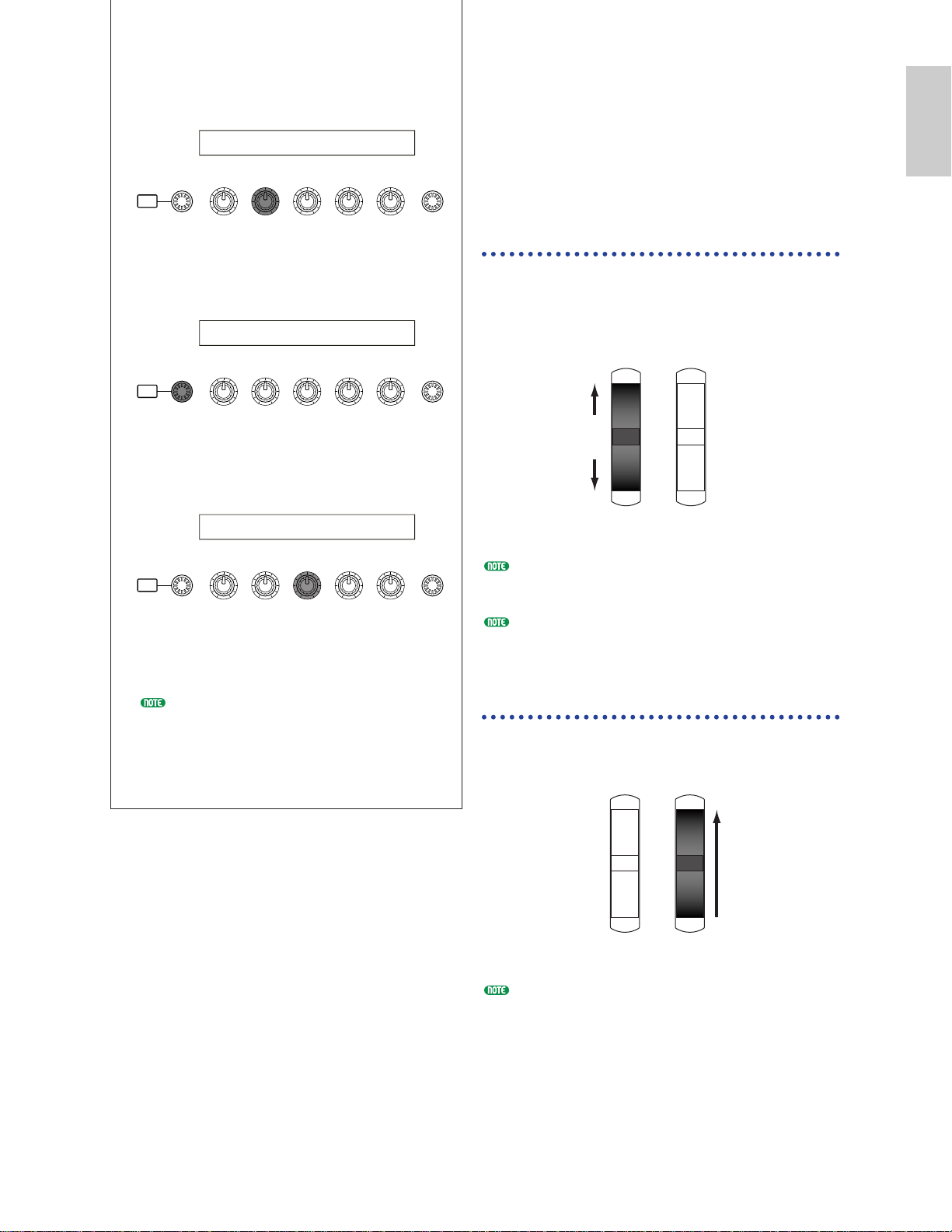
3 Use Knob [B] to select “04:FootCtrl” (Foot
Controller).
4 Use the [PAGE] knob to switch to the CTL
Assign2 (Voice Control Assign 2) screen.
5 Use Knob [C] to select “04:FootCtrl” (Foot
Controller).
Switch to Voice Mode and you are now ready
to use the Foot Controller to control Scenes.
The above procedure is for assigning a Foot
Controller to control Scenes in Voice Mode.
For Performance Mode, follow the same
procedure but at steps 4 and 5, switch to the
CTL Assign2 screen in Performance Edit
Mode.
47
Basics
Section
3
Using Controllers
The CS6x is equipped with Pitch Bend and
Modulation Wheels, plus a Ribbon Controller.
Either of the CS6x and CS6R is equipped with
front panel Knobs [A], [B], [C], [1] and [2], with
which you can control many different parameters.
Pitch Bend Wheel
This wheel’s prime function is to control pitch.
Roll the wheel upward/downward to bend the
pitch upward/downward. The effect can also be
reversed.
Pitch Bend Range can be set for each Voice. The
wheel can also be assigned other parameters (Page
84).
Even if a different parameter is assigned to the
wheel, Pitch Bend messages are still transmitted
through the MIDI Out when it is being used.
Modulation Wheel
The more you roll this wheel upwards, the greater
the modulation that is applied to the sound.
Modulation depth can also be set beforehand. Also,
the wheel can be assigned different parameters, such
as Volume or Pan (Page 84).
CTRL Scene) Scene Contr ol
Sys 04[FootCtrl ]
SHIFT PAGE
/
ELEMENT
PART
CTRL Assign2) FC RB----Mode
Vce [ off ] 00 22 hold
DATAA B C 1 2
SHIFT PAGE
PART
/
ELEMENT
DATAA B C 1 2
CTRL Assign2) FC RB
Vce [FootCtrl] 04 22
SHIFT PAGE
PART
/
ELEMENT
DATAA B C 1 2
Pitch Up
Pitch Down
Pitch Bend
Wheel
Modulation
Wheel
Deeper
Pitch Bend
Wheel
Modulation
Wheel
Page 48

48
Basics
Section
Foot Controller (CS6x)
An optional Foot Controller (such as the FC7),
connected to the FOOT CONTROLLER jack
(Page 18) on the rear panel, can be assigned a
number of controller parameters. By using a foot
controller for parameter control, both your hands
are left free to play the keyboard (or to operate
other controllers). This is very convenient if you
are playing live.
Foot Controller parameters can be set for each Voice.
Foot Switch (CS6x)
An optional Yamaha FC4 or FC5 Foot Switch
connected to the rear panel FOOT SWITCH jack
(Page 18) can be assigned to a range of
parameters. It is suited for a switch-type (on/off)
controls such as Portamento Switch,
increment/decrement of a Voice or Performance
Number, start/stop of the Sequencer, holding
Arpeggiator on or off. The Foot Switch is not
well suited for continuous control. You could also
use it to switch to between different Voices or
Performances
The parameter assigned to the Foot Switch is set in the
CTRL Other screen of Utility Mode (Pages 52, 165).
Sustain (CS6x)
With an optional Yamaha FC4 or FC5 Foot Switch
connected to the SUSTAIN jack (Page 18) on the
rear panel. This is useful when playing pianotype sounds.
You cannot assign a function other than Sustain to
the SUSTAIN jack.
Foot Volume (CS6x)
Connect an optional Foot Controller (such as the
FC7) to the FOOT VOLUME jack of the rear
panel (Page 18). You can then use your foot to
control Main Volume or Expression parameters,
leaving your hands free to play the keyboard. This
is very useful if you are playing live.
The parameter assigned to the Foot Volume
controller is set in the CTRL Other screen of Utility
Mode (Page 165).
Breath Controller
You can connect an optional Breath Controller
(BC3) to the BREATH jack (Page 18) on the rear
panel (or the front panel of the CS6R). Then use
it to control a large number of the synthesizer’s
parameters, particularly those controlled by a wind
player’s breath: dynamics, timbre, pitch and so on.
The Breath Controller is ideally suited for realistic
expression with wind instrument type Voices.
Breath Controller parameters can be set for each
Voice.
Ribbon Controller (CS6x)
The Ribbon Controller is a touch-sensitive
controller that lets you control, say, Filter Cutoff
in real time by running a finger lightly across its
surface to the left or right. Normally, its assigned
parameter will increase in value as you run you
finger to the right, though you can set it to do the
opposite. The Ribbon Controller can be assigned
many different parameters (Page 84).
Ribbon Controller parameters can be set for Utility
Mode (Pages 164, 169).
Knobs [A]/[B]/[C]/[1]/[2]
In Voice/Performance Play Mode, Knobs [A], [B],
[C], [1] and [2] can be used as real-time controllers.
Knobs [A], [B] and [C] are assigned to control the
equalizer gain of, respectively, EQ Low, EQ Mid
and EQ Hi. With Knobs [1] and [2], you are free to
assign different parameters per Voice.
If you turn any knob clockwise, the value assigned
to it is incremented. Conversely, the value is
decremented if you turn it the other way.
Common system parameters are assigned to Knobs
[A],[B] and [C] (Pages 50, 165). Voice-specific
parameters are assigned to Knobs [1] and [2] (Pages
51, 84).
A preset of suitable parameter settings is assigned to
each Voice. By using each knobs [1] and [2], you are
in effect adjusting these settings by a certain
amount. If these parameters are already preset at
their minimum or maximum settings, the settings
cannot be exceeded.
In any Edit Mode, Knobs [A], [B], [C], [1] and [2] are
used for entering parameter settings on screen (Page 24).
SYSTEM
CURSOR
SHIFT PAGE PART
A B C 1 2
/
ELEMENT DATA
Page 49

49
Basics
Section
Aftertouch
Aftertouch lets you, for example, add vibrato to a
sound by applying further pressure to a note on the
keyboard while it is being held down. (With the
CS6R, an aftertouch-sensitive controller keyboard
must be connected.) This allows real-time
expression and control. Aftertouch can be used to
control a wide variety of parameters (Page 84).
Control Sets
Aside from their default parameters, keyboard
aftertouch, the controllers and some of the knobs
on the front panel can be assigned with various
parameters, as explained on Page 47. For
example, you could assign Resonance to the
Modulation Wheel and set aftertouch to apply
vibrato. You are free to assign parameters to suit
the kind of sound being played.
These controller assignments are known as Control
Sets. As the following illustration shows, you can
assign up to six different Control Sets per Voice.
For each Phrase Clip, you can assign up to four
different Control Sets. Within each Control Set,
the controller is known as the Source (Src) and the
parameter controlled by the Source is known as the
Destination (Dest). There are various Dest
parameters available; some will apply to the Voice
as a whole, while some will be specific to each of its
Elements. Details are given in the Controls List of
the separate Data List.
Details about the available Dest parameter settings
are given in the Destination Parameter List of the
separate Data List.
The Element Switches (Page 85) will be disabled if
the Dest parameter setting is not specific for
Elements (i.e., for settings 00 to 33).
By creating Control Sets, you can change sounds
in a variety of ways.
For example, set the Src (Source) parameter of
Control Set 1 to MW (Modulation Wheel) and the
Dest (Destination) parameter to ELFO-PM
(Element LFO Pitch Modulation Depth). Then
set the Src parameter of Control Set 2 also to MW,
but set the Dest parameter to ELM PAN (Element
Pan). You will also need to specify the Element to
be controlled and also the depth (amount) of
control.
In this example, when you move the Modulation
Wheel upward, the amount of Pitch Modulation
increases accordingly, the Element is panned from
left to right. So in other words, you can assign
several Dest parameters to each Src controller.
Continuing from the example above, now create
another Control Set where Src is set to FC (Foot
Controller) and Dest is set to ELFO-PM (Element
LFO Pitch Modulation Depth). Again, specify the
Element to be controlled and also the depth of
control.
Now, Pitch Modulation is assigned to both the
Modulation Wheel and Foot Controller. In other
words, you can also assign several Src controllers
to each Dest parameter.
By assigning all six Control Sets, you will have a
stunning degree of real-time control over the
synthesizer’s sounds.
ELFO-PM
Dest
ELFO-PM
Dest
SET 1 SET 3
Src
MW
(Modulation Wheel)
Src
FC
(Foot Controller)
You can control the
pitch modulation effect
using either of
Modulation Wheel
(MW) and Foot
Controller (FC).
ELFO-PM
Dest Param
ELM PAN
Dest Param
SET 1 SET 2
Src
MW
(Modulation Wheel)
Src
MW
(Modulation Wheel)
Moving the Modulation
Wheel changes the amount
of Pitch Modulation plus the
pan position.
Voice
Control Sets
1~6
Src(Source)
Controller
RB,MW,etc
Dest(Destination)
Control Parameters
Depth
Depth of control
ON/OFF ON/OFF ON/OFF ON/OFF
Elements 2 3 4
1
Page 50

Control Sets and External MIDI Control
In a Control Set, the controllers are assigned to the
internal parameters of the synthesizer. However,
some controllers were originally designed for a
particular purpose, and send pre-defined MIDI
Control Change messages when used, regardless of
their Control Set allocations within the
synthesizer.
For example, the Pitch Bend Wheel, Modulation
Wheel and keyboard aftertouch were originally
designed to control pitch bend, modulation and
aftertouch. Therefore, when you use these
controllers, pitch bend, modulation and aftertouch
information is always sent to the MIDI Out.
Let’s say the Pan parameter is assigned to the
Pitch Bend Wheel in a Control Set. Now,
when you move the Pitch Bend Wheel, the
internal tone generator of the synthesizer will
pan the sound but at the same time, the
original pre-defined Pitch Bend messages will
still be sent to the MIDI Out.
The controllers can also send MIDI Control
Change messages to control the parameters of
external MIDI devices. These assignments are
found in the VOICE (Vce) CTRL Assign1/2
screen of Utility Mode.
As Pitch Bend Wheel, Modulation Wheel and
keyboard aftertouch is pre-defined with specific
MIDI controls, you cannot assign MIDI
Control Changes.
You can also set up a controller such that it
sends one kind of Control message to the
synthesizer’s internal tone generator yet
another kind to the MIDI Out.
For example, in a Control Set you could assign
resonance to Assignable Knob [1]. Then, in the
VOICE CTRL Assign2 screen of Utility Mode,
you could assign Control Change Number 1
(Modulation) to the same knob. Now, when
you turn the knob, resonance will be applied to
the sound of the internal tone generator but at
the same time, modulation information will be
sent to the external MIDI device connected to
the MIDI Out.
This aspect of the synthesizer makes it ideal for
use as a master controller for controlling external
MIDI devices. Add an optional Foot Controller
or Breath Controller for even more control.
50
Basics
Section
Assigning Parameters to Knobs [A], [B] and [C]
The following procedure explains how you can
assign a desired parameter to Knob [A], [B] or [C].
You can assign any parameters that are common
throughout the system (for all Play Modes) and
any MIDI Control Change Numbers. In the
example, Knob [A] will be set up to control Reverb
Return.
1 Press the [UTILITY] key to enter Utility Mode.
2 Use the [PAGE] knob to switch to the CTRL
KnobA (System Control Knob A) screen.
3 Use Knob [2] to select REV-Rtn (Reverb
Return).
Now you can use Knob [A] for on-the-fly
control of the Reverb Return level in
Voice/Performance/Phrase Clip Play Mode.
Note that you can also send (by turning Knob
[A]) or receive Control Change messages with
the Controller Number set in the CC#
parameter through MIDI In and Out.
For assignable parameters, refer to “System
Controller Destination Parameters” in the
separate Data List.
MODE
VOICE PERFORM
MIDI
Pitch Bend
Wheel
Tone Generator
OUT IN
MIDI Control
Control Set
Pitch
LFO1 PAN
UTILITY CARD
EDIT
JOB
COMPARE
STORE
CTRL KnobA) CC# Dest
Sys 01[ModWheel ] EQLow-G
SHIFT PAGE
PART
/
ELEMENT
DATAA B C 1 2
CTRL KnobA) CC# Dest
Sys 01[ModWheel ] REV-Rtn
SHIFT PAGE
PART
/
ELEMENT
DATAA B C 1 2
Page 51

51
Basics
Section
Assigning Parameters to Knobs [1] and [2]
The following procedure explains how you can
assign a desired parameter to Knob [1] or [2].
You can assign controllers to each Voice (or
Part in a Performance) or Clip Kit. Control
Settings can be assigned as a Control Set, and a
each Controller can be used to control multiple
parameters (although this varies according to
the type of Voice or Clip kit). Here we
introduce an example of how to set up Control
Set 1 for Internal Voice 001 (A01) by assigning
PCH-Crs (Pitch: Coarse) to Knob [1].
You can also assign, separately, a different
MIDI Control Change Number to the same
knob in Voice Mode and Performance Mode.
Details are given on Page 168.
1 Press the [VOICE] key to enter Voice Play Mode.
2 Select Internal Voice 001 (A01) and press
the [EDIT] key to enter Voice Edit Mode.
3 Use the [PAGE] knob to switch to the CTL
Set1 (Control Set 1) screen.
4 Use Knob [B] to assign “KN1 (16)” (Knob
[1]) to the Src (Source) parameter.
SHIFT PAGE
PART
/
ELEMENT
DATAA B C 1 2
CTLíSet1) Src Dest EL Sw Depth
C 1234 KN1(16) FLT-Rez --34 +14
SHIFT PAGE
PART
/
ELEMENT
DATAA B C 1 2
CTL Set1) Src Dest EL Sw Depth
C 1234 MW(01) FLT-Rez --34 +14
VOICE PERFORM
UTILITY CARD
EDIT
COMPARE
JOB
STORE
MODE
5 Use Knob [C] to assign PCH-Crs
(Pitch:Coarse) to the Dest (Destination)
parameter.
6 Use Knob [1] and the [DATA] knob to specify
the Element to be controlled. Knob [1] moves
the cursor (blinking) and the [DATA] knob
displays the Element to be controlled.
7 Use Knob [2] to set the Depth parameter.
The larger the setting, the greater the depth
of control.
8 Store the edited Voice (Page 116).
Now you have Internal Voice 001 (A01)
assigned PCH-Crs (Pitch:Coarse) to Knob [1].
When you select and play this Voice in Voice
Play Mode, you can control the pitch of the
Voice if you turn Knob [1].
Details about the assignable control functions
are given in the Control Set Destination
Parameters in the separate Data List.
CTLíSet1) Src Dest EL Sw Depth
C 1234 KN1(16) PCH-Crs --34 +14
SHIFT PAGE
PART
/
ELEMENT
DATAA B C 1 2
CTLíSet1) Src Dest EL Sw Depth
C 1234 KN1(16) PCH-Crs 1--4 +14
SHIFT PAGE
DATAA B C 1 2
/
ELEMENT
PART
CTLíSet1) Src Dest EL Sw Depth
C 1234 KN1(16) PCH-Crs 1234 +34
SHIFT PAGE
PART
/
ELEMENT
DATAA B C 1 2
Page 52

Controlling Parameters by Foot Controller (CS6x)
By connecting an optional Foot Controller
(such as the FC7) to the FOOT
CONTROLLER jack on the rear panel of the
synthesizer, you can control various
parameters by foot without having to use your
hands. In the following example, we introduce
how to set up Foot Controller to work as
Modulation Wheel.
1 Press the [UTILITY] key to enter Utility
Mode.
2 Use the [PAGE] knob to switch to the CTRL
Assign2 (Voice Control Assign 2) screen.
SHIFT PAGE
PART
/
ELEMENT
DATAA B C 1 2
CTRL Assign2) FC RB
Vce [ off ] 00 22
VOICE PERFORM
UTILITY CARD
EDIT
COMPARE
JOB
STORE
MODE
CS6x
SUSTAIN
FOOT
SWITCH
FOOT
CONTROLLER
FOOT
VOLUME
INDIVIDUAL OUTPUT
1
2
OUTPUT
R L MONO
PHONES LINE1 MIC
LINE 2
A D INPUT
GAIN
FC7
52
Basics
Section
3 Use Knob [C] to select “01:ModWheel”
(Modulation Wheel).
In Voice Mode, the foot controller can now be
used to control Modulation.
If the current Voice has a Control Set with a
source (Src) assigned to Modulation Wheel
(MW) and receives a Control Change message
of Modulation Wheel, a destination (Dest)
parameter for the source (MW) will be
affected with that message.
The above procedure explains how to set up
the Foot Control to control Modulation in
Voice Mode. To create such a setup for
Performance Mode, the appropriate settings
are found at the CTL Assign2 screen in
Performance Edit Mode.
Switching Between Programs by Foot Switch (CS6x)
By connecting an optional Foot Switch (such
as the FC4 or FC5) to the FOOT SWITCH
jack on the rear panel of the synthesizer, you
can switch between Programs without having
to use your hands. For example, if you
consecutively arrange the Voices/Performances
in memory, you can switch between them
easily in a live performance. The following
procedure explains exactly how to a about this.
CS6x
SUSTAIN
FOOT
SWITCH
FOOT
CONTROLLER
FOOT
VOLUME
INDIVIDUAL OUTPUT
1
2
OUTPUT
R L MONO
PHONES LINE1 MIC
LINE 2
A D INPUT
GAIN
FC4
or
FC5
CTRL Assign2) FC RB
Vce [ModWheel] 01 22
SHIFT PAGE
PART
/
ELEMENT
DATAA B C 1 2
Page 53

53
Basics
Section
1 Press the [UTILITY] key to enter Utility
Mode.
2 Use the [PAGE] knob to switch to the CTRL
Other (System Control Other) screen.
3 Use Knob [B] to select “099:PC Inc”
(Program Change Increment).
In Voice/Performance/Phrase Clip Mode, the
Foot Switch can now be used to switch
between programs.
Alternatively, you can assign other functions
such as Arpeggio Switch (On/Off), Sequencer
(Play/Stop) and so on (Page 165).
4 Phrase Clips
Real-world sounds can be recorded or loaded into
the synthesizer and played back as musical
instruments sounds. The waveform data held in
the synthesizer are knows as Phrase Clips.
These Phrase Clips are created and played back in
Phrase Clip Mode (Page 142). A basic overview
of Phrase Clips is given here.
Phrase Clips Overview
As shown in the following illustration, on the rear
panel (or the front panel of the CS6R), there is an
A/D INPUT jack for inputting analog sources to
the A/D converter. The A/D converter then
converts the signals from these analog sources
into digital binary signals through a process
known as “sampling.” Within the synthesizer,
these sampled signals are called Phrase Clips, and
up to 256 of these Phrase Clips can be held within
the 4MB of internal memory. You can assign
Phrase Clips to any keys on the keyboard to play
them back. A collection of Phrase Clip keyboard
assignments is known as a Clip Kit, of which you
can create up to four. You can then assign Clip
Kits to Performances, just like with Voices.
When playing back Phrase Clips, the processing of
signals is the opposite of A/D conversion. The
digital signals are passed through a D/A converter
to convert them back to analog form.
256 phrase clips
4MB Internal Memory
A/D
Converter
D/A
Convertor
Analog Signal
Clip Kits
Analog
signal
AD INPUT
DRAM
Digital
Binary
MODE
VOICE PERFORM
UTILITY CARD
EDIT
JOB
COMPARE
STORE
CTRL Other) FS
Sys 088[ ------ ]
SHIFT PAGE
PART
/
ELEMENT
DATAA B C 1 2
CTRL Other) FS
Sys 099[PC Inc ]
SHIFT PAGE
PART
/
ELEMENT
DATAA B C 1 2
Page 54

54
Basics
Section
Sampling Rate and Bit
Resolution
As an example, the illustration shows a sine wave.
When recording (sampling) the sine wave, the
A/D converter basically takes snapshots of the
wave’s levels at fixed intervals in time.
In the graph, the horizontal axis represents time
and the vertical axis represents signal level.
The number of snapshots of levels taken in one
second is known as the sampling rate and is given
in Hertz. The A/D converter of this synthesizer
has a sampling rate of 44.1kHz, which means that
it takes 44100 snapshots of the waveform’s levels
within one second. The higher the sampling rate,
the closer the reproduced (digital) signal is to the
original.
On the vertical axis, the number of levels is given in
bits and is known as the bit resolution. The A/D
converter of this synthesizer has a bit resolution of
16 bits, which means that there are 2
16
(i.e., 65536)
levels on the vertical axis. As with the sampling rate,
the higher the bit resolution, the closer the
reproduced (digital) signal is to the original.
Incidentally, audio on CDs is also sampled at
44.1kHz in 16 bits.
Figure A: Lower sampling rate and bit resolution
Figure B: Higher sampling rate and bit resolution
Level
Time
Level
Time
Time
Level
Sampled waveform
Level
Time
Original Analog Signal
Playing Back Phrase Clips
You can play back your Phrase Clips in three
different ways, as follows.
First, there is “loop” playback. A section of the
Phrase Clip is continuously looped during
playback. This is often used for creating drum
pattern loops from breakbeats.
When you play a note on the keyboard, the
Phrase Clip plays from the start point to the end
point. It then returns to the loop point and plays
to the end point again, and keeps doing this until
you release the note.
With musical instruments in general, the
characteristic part of the sound (the “attack” section)
is usually at the beginning, just after the start point.
After this, the sound does not vary a great deal while
the note is being held, and you can set the loop and
end points at either end of this section. When
playing back a Phrase Clip of an instrument that has
been looped like this, the attack section of the sound
is played back once and then the looped section is
played back continuously until you release the note.
Looping is also way of creating usable instrument
sounds without using up too much memory.
The second playback method is known as “one
shot.” When you press a note on the keyboard,
the Phrase Clip plays from beginning to end just
once. This type of playback is commonly used for
Phrase Clips of drum and percussion sounds.
Third, you can select “reverse” playback. When
you press a note on the keyboard, the Phrase Clip
plays from end to beginning just once. This is
useful for creating reversed cymbal sounds and
other special effects.
You can set points and playback modes for the
loop in Phrase Clip Edit Mode (Page 146).
Start Point End Point
Start Point End Point
Start Point Loop Point
Phrase Clip Looped Playback
End Point
Page 55

55
Basics
Section
Creating a Clip Kit
You can assign Phrase Clips to notes on the
keyboard (C0 to C6) and play them live or using a
sequencer. You can also edit various parameters
for each Phrase Clip. The assignment of Phrase
Clips across the keyboard is known as a Clip Kit,
and you can create up to four of these.
You can assign each Phrase Clip to one note on
the keyboard. However, by assigning breakbeats
and other rhythmic loops plus percussive Phrase
Clips used in the rhythms, you can create a Clip
Kit specifically for rhythms only. Or you could
assign Phrase Clips of unusual sounds to create a
Clip Kit of special effects. Essentially, you can
create a Clip Kit consisting of any sounds that suit
your needs.
Clip Kits can be treated the same as Voices and
Performances. For instance, in Phrase Clip Play
Mode, you can play Clip Kits directly using the
keyboard (Page 142). In Performance Mode, a
Clip Kit can be included as a Part in a
Performance (Page 129).
You can further edit Clip Kits and Phrase Clips in
Edit Mode (Page 146) and perform jobs on them in
Job Mode (Page 154).
When you switch off your synthesizer, the Clip Kit will
be lost. Always save important data to Memory Card.
Recording a Phrase Clip
This section explains how to record a Phrase Clip,
set the loop and so on, execute jobs, and create a
Clip Kit.
You can create a Phrase Clip by recording from a
microphone, CD player or some other audio
equipment, or from an existing
Voice/Performance/Phrase Clip in the synthesizer.
As a simple example, we will record the drum
pattern that was created earlier using the
Arpeggiator and Drum Voice.
1Before entering Phrase Clip Mode, first enter
Voice Play Mode and press the MEMORY
[PRE1] and [PRE2] keys simultaneously. Then
use the [DATA] knob, the [DEC/NO] and
[INC/YES] keys or the PROGRAM keys (CS6x)
to select the Preset Drum Voices (DR1).
2Now press the PHRASE CLIP key (its LED will
light) to enter Phrase Clip Mode.
3Hold down the PHRASE CLIP [REC] key and
the following screen will be displayed. Here,
you can assign a key to the Phrase Clip you are
about to record. While still holding down the
key simply press the respective key on the
keyboard. Here, we will assign note C1. Now
release the [REC] key to switch to the
Recording screen.
4Use Knob [B] to set the Source parameter to
“voice” The Drum Voice you selected earlier
can now be played on using the keyboard.
5Use Knob [C] to set the Trigger parameter to
“key.” With this setting, the recording process
will begin when you press a note on the
keyboard.
6Press the ARPEGGIO [ON/OFF] key on the
front panel (its LED will light) to switch the
Arpeggiator on. When you press a note on the
keyboard, a drum pattern will now play back
according to the Arpeggiator settings. You can
adjust the tempo using the SEQ PLAY
[TEMPO] knob on the front panel. Before
proceeding further, make sure that you have
selected the correct sound.
With the CS6R, select the Drum Voice, enter
Drum Voice Edit Mode (Page 102), set it’s
Arpeggio Switch parameter to “on,” and then
enter Phrase Clip Mode.
To prevent the deterioration in sound quality
when recording, you should set a high output
level for the Voice (in Voice Edit Mode).
PHRASE CLIP
PITCH
REC
Press and hold down
PCLP Rec) >> Select Record Key <<
>> C 1:off[ ] <<
Clip
C1 C6
C0 C6
PCLP Rec) Source Trigger [ENTER]
(Key=C 1) voice key toStandby
Page 56

56
Basics
Section
!In Phrase Clip Edit Mode, use the [PAGE] knob
to switch to the OSC Asgn screen. Normally
you would assign the Phrase Clip to a note on
the keyboard (Clip Key) here. However, since
we have already assigned it to note C1 in step
3 the Phrase Clip name and number ([Clip
001]) will be displayed when you press note C1
on the keyboard or use Knob [A] to call up C1.
When you press C1 to assign a Clip Key, the
Phrase Clip will be played back.
Since it is somewhat inflexible to assign the
Phrase Clip to just C1, we will also assign it to
the white notes from D1 to C2. Select each
respective notes by pressing it on the keyboard
or by using Knob [A], and use Knob [B] to
assign [Clip 001] to each.
At the same screen, use Knob [1] to select a
Variation.
A Variation refers to the method by which the
Phrase Clip (including its loop points and other
parameters) is played back. Using a Variation, each
Phrase Clip can have up to eight different loop
points. For example, when applied to the drum
pattern Phrase Clip recorded earlier, Variations can
be used to create a 1-bar loop pattern, a reversed
pattern and other different playback styles.
You have assigned the same Phrase Clip ([Clip
001]) to the white notes between C1 and C2.
Now you can assign a different Variation to each
of the notes. Select each respective note by
pressing it on the keyboard or by using Knob
[A], and use Knob [1] to assign a different
Variation number (1 to 8) to each.
At this stage, the Variations themselves have not
been set so Variations 1 to 8 will all play the
Phrase Clip back in the same way. However,
once you have set up all the Variations, the same
Phrase Clip can be played back differently for
each white note between C1 and C2.
SHIFT PAGE
PART
/
ELEMENT
DATAA B C 1 2
OSCíAsgn) Number Variation [ENTER]
Key= C 1 1[Clip 001 ] 1 to Edit
SHIFT PAGE
PART
/
ELEMENT
DATAA B C 1 2
OSCíAsgn) Number Variation [ENTER]
Key= C 2 1[Clip 001 ] 1 to Edit
SHIFT PAGE
PART
/
ELEMENT
DATAA B C 1 2
OSCíAsgn) Number Variation [ENTER]
Key= C 1 1[Clip 001 ] 1 to Edit
7Press the [ENTER] key and the Recording
Standby state is entered. You will see the
“Waiting for trigger...” message.
8Recording will begin when you press the
respective note on the keyboard. Press the note
and let the drum pattern play for one bar.
9Press the [EXIT] key. Recording will finish and
the “Now Working...” message will be
displayed.
The recorded Phrase Clip is now assigned to
note C1, as set in step 3. At this point, you
can audition the recorded Phrase Clip by
pressing note C1 while holding down the [REC]
key.
There may be cases where a recorded volume level
differs from one you monitored while recording. It
is an effect by the automatic level adjustment
function that corrects a recorded level for a proper
playback. In these cases, you can adjust a playback
level of the Clip in Phrase Clip Edit Mode. If you
want to increase the entire volume, you can use the
EQ Type parameter to set a value of “Boost12”.
If you are not satisfied with the result, you can
repeat the recording by pressing the [ENTER]
key.
)Once you exit Phrase Clip Record Mode, the
recorded Phrase Clip will automatically be
saved to memory (DRAM) with a new number
and name (Clip 001).
Here, do not exit Phrase Clip Record Mode.
Instead, press the [EDIT] key to enter Phrase
Clip Edit Mode.
Editing the Phrase Clip
Continuing from step ) above, you are now ready
to edit the Phrase Clip you have just recorded. In
Phrase Clip Edit Mode, you can assign Phrase
Clips to notes on the keyboard (between C0 and
C6) to form a Clip Kit, create loops, edit the tonal
characteristics and so on. Here, we will edit the
recorded Phrase Clip in several ways.
EF
BYPASS
MASTER
KEYBOARD
EXIT ENTER
DEC/NO INC/YES
PCLP Rec) Source Trigger [EXIT]
<< Waiting for Trigger... >> toStop
Page 57

57
Basics
Section
@Check that note C1 is selected, then press the
[ENTER] key. The Variation parameters for
[Clip 001] will be displayed.
To return to the previous screen, press the [EXIT]
key.
#Use Knob [A] to select the Variation number.
We will start with Variation 1.
$As explained earlier (Page 54), the Play
parameter specifies how the Phrase Clip is
played back. There are three possible settings
for this parameter, but we will select “reverse”
here. Use Knob [B] to select.
Now press note C1 on the keyboard and check
that the Phrase Clip has indeed been reversed.
Reverse playback involves the sound being played
in reverse from the End point to the Start point.
You can change the length by simply adjusting
these points. When you record a Phrase Clip, the
Start point is initially set at the beginning of the
recording and the End point at the end of the
recording.
%Press the [EXIT] key to return to the OSC Asgn
(Oscillator Assign) screen. This time, select the
D1 note and press the [ENTER] key.
^Next, select Variation 2 but set the Play
parameter to “loop” this time. When you press
note D1 at this point, the Phrase Clip is simply
played back as a loop between the Start and
End points of the recording. If you only want
one part of the Phrase Clip to be played back as
a loop, you need to set the Start/Loop/End
points. As an example, we will set a loop
exactly one bar in length.
&Use Knob [C] to set the Start point (the point at
which playback will begin when you press a
note). To create a 1-bar looped drum pattern,
you need to press note D1 and adjust the Start
point so that it matches up with the first beat
in the bar.
*Use Knob [1] to set the Loop point (the start of
the section to be looped). Since you will be
creating a loop exactly one bar in length, the
Loop point can be set to the same position as
the Start point.
(Use Knob [2] to set the End point (the end of
the section to be looped). For a 1-bar drum
pattern, you need to set the End point at the
end of the fourth beat in the bar (i.e.,
immediately before the first beat of the next
bar). Press note D1 and keep adjusting the End
point until you find the ideal point for looped
playback.
SHIFT PAGE
PART
/
ELEMENT
DATAA B C 1 2
PCLPíVar) Play Star t Loop End
(D 1) 2: loop 11912 0 119120 452316
SHIFT PAGE
PART
/
ELEMENT
DATAA B C 1 2
PCLPíVar) Play Star t Loop End
(D 1) 2: loop 11912 0 119120 236378
SHIFT PAGE
PART
/
ELEMENT
DATAA B C 1 2
PCLPíVar) Play Star t Loop End
(D 1) 2: loop 11912 0 0 236378
EF
MASTER
KEYBOARD
BYPASS
EXIT ENTER
DEC/NO INC/YES
PCLPíVar) Play Start Loop End
(C 1) 1: loop 0 0 236378
PCLPíVar) Play Star t Loop End
(C 1) 1: loop 0 0 236378
SHIFT PAGE
/
ELEMENT
PART
DATAA B C 1 2
PCLPíVar) Play Star t Loop End
(C 1) 1: reverse 0 0 236378
SHIFT PAGE
PART
/
ELEMENT
DATAA B C 1 2
Page 58

58
Basics
Section
[Clip 001] is now reversed as Variation 1 and
looped for one bar as Variation 2, and both
Variations can be played by pressing notes C1 and
D1. In the same way, you can change the points
for Variations 3 to 8 and set up different loops to
that of Variation 1/2.
Therefore, each Phrase Clip can be played back in
a variety of ways according to different notes on
the keyboard, and you can assign completely
different Phrase Clips with different Variations to
other notes. Such a collection of Phrase Clips and
Variations is known as a “Clip Kit.”
ºNext, press the [JOB] key to enter Phrase Clip
Job Mode. We will now take a quick look at
how to execute a Job.
Executing a Job
In Job Mode, you can perform various operations
(Jobs) on your edited Phrase Clips. You can copy
and delete items, create Variations, use Loop
Remix and Extract to modify your Phrase Clips
and so on. In this example, the totally unique
Loop Remix feature will be explained. The
explanation continues from step º above.
¡In Phrase Clip Job Mode, use the [PAGE] knob
to switch to the PCLP LoopRemix screen. Loop
Remix takes the data from an existing Phrase,
changes it around, and creates a separate new,
looped Phrase Clip. (The original Phrase Clip
remains in its original state and a completely
new Phrase Clip is created with Loop Remix.)
By setting the Type and Vari parameters, you
can easily create a variety of new Phrase Clips.
™By pressing the respective note on the keyboard
or by using Knob [A], you can select the source
Phrase Clip to which Loop Remix will be
applied. Let’s select [Clip 001] as the source
and create a new Phrase Clip. If you have
followed the previous procedure and assigned
Variations to the white notes between C1 and
C2, you can press any of these notes; [Clip 001]
will still be selected.
SHIFT PAGE
PART
/
ELEMENT
DATAA B C 1 2
PCLP LoopRemix) Type Vari
Job C 1:001[Clip 001] 1 A
£Use Knob [1] to set the Type parameter, which
specifies the type of loop change (i.e., which
part of the loop will be modified). Combined
with the Vari parameter, it is possible to create
a variety of loop patterns using Loop Remix.
There are five Types in total, and we will use
Type 2 here.
¢Use Knob [2] to set the Vari (Variation)
parameter, which specifies the amount by
which the loop will be modified. The four
available Variations (A to D) apply increasing
amounts of modification. Let’s select “D” here
in order to create the largest modification.
∞Press the [ENTER] key and you will see a
confirmation message. Now press the
[INC/YES] key to confirm and the Loop Remix
will be executed on [Clip 001] using the Type
and Vari parameters set earlier. To cancel the
operation, press the [DEC/NO] key
After the Loop Remix operation has completed,
you will see the following message.
At this point, you can press the note on the
keyboard assigned to [Clip 001] and listen to
the sound after Loop Remix has been applied.
You should hear a completely new type of
pattern, including reversed sections of sound.
However, if you are not satisfied with the
result, you can repeat steps £ to ∞ and apply
Loop Remix by pressing the [INC/YES] key at
the present screen. By changing the
combination of Type and Vari parameter
settings, you should be able to create loop
patterns that sound completely different.
§Once you have a Phrase Clip that you are
satisfied with, press the [DEC/NO] key at this
screen and you will be returned to the PCLP
LoopRemix screen.
The new Phrase Clip will have a new name and
number, and be assigned to the keyboard in place
of the original Phrase Clip (which is still retained
in memory but is no longer assigned to notes).
Phrase Clips are retained in memory (DRAM) even
after you exit Phrase Clip Mode, and until you
switch the power off. However, if a Clip Kit has
been created after editing or executing a Job, it will
be lost when you exit Phrase Clip Mode. Therefore,
you should always store your Phrase Clips before
exiting this mode. Up to four Clip Kits can be stored
in internal memory. Details about storing Phrase
Clips are given on Page 160.
Once you have created a Clip Kit, you can play it
in Phrase Clip Play Mode or use it as a Part in a
Performance, just as with Voices (Page 129).
PCLP LoopRemix) Type Vari
<< Retry? [YES]/[NO] >> 2 D
Page 59

59
Basics
Section
5
Other Useful Features
Portamento
Portamento is used to create a smooth transition
in pitch from the first note played on the
keyboard to the next, and can be used in Voice or
Performance Mode. You can switch portamento
on/off using the PORTAMENTO [ON/OFF] key
on the front panel. When switched on, the
PORTAMENTO [ON/OFF] key LED will be lit.
You can use the [PORTAMENTO] knob to vary
the pitch transition time (Portamento Time).
Turn the knob clockwise to lengthen the time.
Before enabling portamento, specify how portamento
should work using parameters available in the
Portamento screen (Page 84).
If Portamento is switched on and ready for use, the
PORTAMENTO [ON/OFF] key LED will light when
you select the Voice.
In Performance Mode, you can apply portamento to
Voices of Parts that have their Layer Switch (Page
133) and Portamento switch set to “on” (Page 131).
Depending on the method of storage (Pages 116,
141), the portamento state (on/off) can be saved
with the Voice or Performance.
You can set the portamento state in the Portamento
screen (Pages 84, 131) in Voice or Performance Edit
Mode.
Pan
You can use the [PAN] knob on the front panel to
set the stereo position (pan) of the currently
selected Voice, Performance or Clip Kit. The Pan
parameter can be set in each Edit Mode, but the
front panel [PAN] knob lets you adjust this
parameter in real time in any of the Play Modes.
On the CS6R, this is set at the QED Level screen
(Page 81).
PORTAMENTO
ON
/
OFF
PAN
PAN
Page 60

1 Selecting a Voice to Edit
Enter Voice Play Mode by pressing the [VOICE]
key.
Select the Voice Number of the Voice you wish to
edit (Page 75).
Before editing, first enter Voice Job Mode and copy
the Voice you wish to edit to internal user memory.
If you are creating a Voice from scratch, use the
Initialize function to initialize a Voice in internal
user memory. Details are given on Page 115.
2 Entering Voice Edit Mode
Voice creation/editing is carried out in Voice Edit
Mode.
To enter Voice Edit Mode, press the [EDIT] key
while in Voice Play Mode.
Common Edit and Element Edit
Each Voice consists of up to four Elements
(Page 37). The parameters common to all four
Elements are known as Common Edit
parameters. Voice Edit Mode consists of
Common Edit screens, plus screens for each
individual Element’s parameters.
In Voice Edit Mode, you can use Knob [A] to
switch between Common settings and settings
for Elements 1 to 4.
Common settings
Settings for Elements 1 to 4
SHIFT PAGE
PART
/
ELEMENT
DATAA B C 1 2
OSC Wave) Number Ct gry
EL1234 001[Pf:Gran d 1 ]
Element 1~4
GEN Other) Mode Assign M icroTuning
C 1234 poly single 3 1:Indian
Common
VOICE PERFORM
UTILITY CARD
EDIT
COMPARE
JOB
STORE
MODE
60
Basics
Section
There are 256 Normal Voice presets and 8 Drum
Voice presets. You can edit these to create new
Voices, or build completely new Voices from
scratch. You can then store up to 128 of these
new/edited Normal Voices and up to 2 new/edited
Drum Voices to internal user memory or external
Memory Card.
The following procedure gives a basic idea about
how to go about creating/editing Voices.
Of course, this is just one example; you are free to
set any parameters in any way you like. Details
about each parameter are given in the Reference
section of this manual.
All parameter settings are stored along with the
Voice itself.
1In Voice Play Mode, select the Voice you wish
to edit.
2Enter Voice Edit Mode.
3In the Common Edit screens, set the parameters
common to all Elements in the Voice (volume,
pitch, tone, etc.) You can also set parameters
related to the Arpeggiator, Controllers, Effects,
and so on.
4At the OSC (Oscillator) screens, select the
Waves used by the Elements in the Voice, plus
the volume, pan, note range and other basic
parameters.
5At the PCH (Pitch) and PEG (Pitch Envelope
Generator) screens, set the tuning and other
pitch-related parameters used by the Elements.
Also set the PEG parameters as necessary.
6At the FLT (Filter) and FEG (Filter Envelope
Generator) screens, adjust the parameters of
the filters used by the Elements. Also set the
FEG parameters as necessary.
7At the AMP (Amplitude) and AEG (Amplitude
Envelope Generator) screens, set the volume
and other output level-related parameters used
by the Elements. Also set the AEG parameters
as necessary.
8At the LFO (Low Frequency Oscillator)
screens, set the modulation-related parameters
used by the Elements.
9At the EQ (Equalizer) screens, adjust the
equalizer parameters affecting the tonal
characteristics of the Elements.
)Store the edited Voice.
Voice Edit
MODE
VOICE PERFORM
UTILITY CARD
JOB
EDIT
COMPARE
STORE
Page 61

61
Basics
Section
Selecting Elements (CS6x)
In Voice Edit Mode, you can select the Element
to edit by pressing the respective ELEMENT
SELECT key ([1] to [4]). When you select an
Element, the cursor moves to the respective
Element Number.
Example: When “Element 2” is selected
Switching Elements On/Off (CS6x)
In Voice Edit Mode, an Element can be
switched off when you press the respective
ELEMENT ON/OFF key ([1] to [4]). This lets
you temporarily mute other Elements in the
Voice so that you can listen to the changes to
the Element that you are editing. A muted
(off) Element will be indicated as an asterisk
(*) in the display as illustrated below.
Example: When Elements 2 and 3 are
turned off
BANK
A B C D E F G H
1 2 3 4 1 2 3 4
ELEMENT SELECT ELEMENT ON
/
OFF
EQ Param)LoFreq LoGain HiFreq HiGain
EL1**4 274.2Hz +12 2.82kHz +22
off off
BANK
A B C D E F G H
1 2 3 4 1 2 3 4
ELEMENT SELECT ELEMENT ON
/
OFF
EQ Param)LoFreq LoGain HiFreq HiGain
EL12_34 274.2Hz +12 2.82kHz +22
Cursor
COMMON
Element1
Element2
Element3
Element4
Switching Between Screens and Entering Settings
After selecting a Common Edit screen or a edit
screen for an Element (1 to 4), use the [PAGE]
knob to switch to other screens.
There are many parameters available within a
screen. To make editing easier, the knobs
below the LCD are assigned to each of the
parameters in the screen.
Menu Screen
If you use the [PAGE] knob while holding
down the [SHIFT] key, the settings menu will
be displayed. Use the [PAGE] knob to move
the cursor to an item and release the [SHIFT]
key to jump to the screen for that item.
You can also use other knobs and keys to enter
settings. The Compare featureallows you to compare
the sound being edited against the sound prior to
editing. Details are given on Pages 24, 79.
3 Common Edit Screens
Each Voice consists of up to four Elements. Here, the
parameters common to all Elements are explained.
• GEN (Common General)
Here, you can set general parameters in Common
Edit, such as the Voice Name.
GENíName) Ctgry a-Z 0-? Cursor
C 1234 [Pf:Init Voice]
AMP Scale)Ofst1 Ofst2 Pfst3 Ofst4
EL12_34 + 0 + 0 - 21 - 35
SHIFT PAGE
PART
/
ELEMENT
DATAA B C 1 2
AMP Scale)Ofst1 Ofst2 Pfst3 Ofst4
EL12_34 + 0 + 0 - 21 - 35
SHIFT PAGE
PART
/
ELEMENT
DATAA B C 1 2
Cursor
GENíOther) Com:>GEN≥QED> ARP>CTL>LFO>EFF
C 1234 Elem:>OSC>PCH> FLT>AMP>LFO>EQ
SHIFT PAGE
/
ELEMENT
PART
DATAA B C 1 2
Page 62

62
Basics
Section
• QED (Common Quick Edit)
These parameters mostly control the volume and
tone of the Voice and you can easily change the
overall sound. Many of these parameters can be
set directly using the Sound Control knobs on the
front panel of the CS6x.
• ARP (Common Arpeggio)
By setting these parameters, you can control how
the Voice is arpeggiated. Details about how to use
the Arpeggiator are given on Page 42.
• CTL (Common Controller)
You can assign various functions to the controllers
on the front/rear panel. For example, you can
assign parameters to the Pitch Bend Wheel and a
Foot Controller so that you can change the tone of
the Voice in real time. Details about various
different uses are given on Page 47.
• LFO (Common Low Frequency Oscillator)
These are the LFO parameters. The LFO uses a
low frequency waveform to vary the
pitch/filter/amplitude characteristics, and can be
used to create vibrato, wah, tremolo and other
effect (Page 85).
• EFF (Common Effect)
These are the Effects parameters for the Voice.
There are two Insertion Effects plus two System
Effects (Reverb and Chorus).
EFFíInsEF) InsEF Connect
C 1234 1=2
LFOíWave) Wave^ Speed KeyReset Phase
C 1234 trpzd 63 on 270
CTLíSet1) Src Dest EL Sw Depth
C 1234 FC(04) RevTime:EF1 1234 +63
ARPíType) Type Tempo Switch Hold
C 1234 Up&Down1:Sq 120 on on
QEDíLevel) Vol Pan RevSend ChoSend
C 1234 127 C 127 127
4 OSC (Oscillator) Screens
In these screens, you can mainly set the
parameters controlling the waveforms on which
the Voice is based. You can select the Wave used
for the Element, the volume and note range of
each Element and so on.
• OSC Wave
Select the waveform (Wave) used for each Element.
• OSC Out
• OSC Pan
Set the volume (output level) and stereo pan
position of each Element. The following
illustration shows the logic.
• OSC Limit
Set the note range for each Element (the range of
notes on the keyboard over which the Element
will sound) and also the velocity response (the
range of note velocities within which the Element
will sound). You can assign different settings for
each Element. With these parameters, you can
layer Elements and control their output.
For example, you could set one Element to sound
in an upper range of the keyboard, and another
Element to sound in a lower range. Thus, even
within the same Voice, you can have two different
sounds for different areas of the keyboard or you
can make the two Element ranges overlap so that
their sounds are layered over a set range.
Furthermore, you can set each Element to respond
to different velocity ranges so that one Element
sounds for lower note velocities, whereas another
Element sounds for higher note velocities.
Mixer
Elements
Level
Pan (Stereo)
1 2 3 4
OSCíPan) Pan Alter Random Scale
EL1234 C L64 63 +63
OSCíOut) Level Delay InsEF
EL1234 96 0 ins2
OSCíWave) Number Ctgry
EL1234 001[Pf:Grand 1 ]
Page 63

63
Basics
Section
5 PCH (Pitch) and PEG (Pitch EG)
Screens
Set the basic pitch parameters for each Element.
You can detune Elements, apply Pitch Scaling and
so on. Also, by setting the PEG (Pitch Envelope
Generator), you can control how the pitch
changes over time.
• PEG (Pitch Envelope Generator)
Using the PEG, you can control the transition in
pitch from the moment a note is pressed on the
keyboard to the point at which it is released. As
illustrated below, the Pitch Envelope consists of five
Time (transition speed) parameters and five Level
(pitch) parameters. This is useful for creating
automatic changes in pitch. Furthermore, different
PEG parameters can be set for each Element.
Details about PEG parameters are given on Page 91.
OSCíLimit) Note Limit Vel Limit
6 FLT (Filter) and FEG (Filter EG)
Screens
You can use the filter to change the tonal
characteristics of each Element, by adjusting
overtones (harmonic tones) included in the
waveform from the Element. There are several
types of filters, but its basic idea is similar. As
illustrated below, the filter is used to pass overtones
at specific frequencies and cut off (does not pass)
others, to alter the harmonic factor of an original
waveform. You can determine such frequencies by
specifying a pointing or center frequency (cutoff
frequency). With some filters, you can adjust signal
levels at several frequency bands. You can also set
the Filter Envelope Generator (FEG) for time
variance of how the filter works, which results in a
dynamic change in tonal characteristics. Here we
introduce how FEG works.
Details about Filter Types are given on Page 93.
• FEG (Filter Envelope Generator)
Using the FEG, you can control the transition in
tone from the moment a note is pressed on the
keyboard to the point at which it is released. As
illustrated below, the Filter Envelope consists of
five Time (transition speed) parameters and five
Level parameters (for the amount of filtering).
When you press a note on the keyboard, the cutoff
frequency will change according to these envelope
settings. This is useful for creating automatic wah
effects, for example. Furthermore, different FEG
parameters can be set for each Element.
Details about FEG parameters are given on Page 95.
EL1234 C-2 - G 8 1 - 127
Velocity
Element 1
C-2
Element 3
Element 2
Element 4
G8
Level
Cutoff range Cutoff range
Range passed
PEGíTime) Hold Attack Decay1 Decay2
EL1234 127 127 127 127
Pitch
0
Hold Level
Hold
Time
Attack
Time
Attack
Level
Decay1
Decay1
Time
Level
Decay2
Time
Sustain
Level Key off
Release
Time
Release
Level
Time
Center frequency
Time
FEGíTime) Hold Attack Decay1 Decay2
EL1234 127 127 127 127
Level
Hold Level
Attack
Level
Decay1
Level
Sustain
Level Key off
Release
Level
0
Attack
Hold
Time
Time
Decay1
Time
Decay2
Time
Release
Time
Time
Page 64

64
Basics
Section
7 AMP (Amplitude) and AEG
(Amplitude EG) Screens
Set the volume of each Element after the OSC
(Oscillator), PITCH and FILT (Filter) parameters
have been applied, and also the final overall
volume of the signal sent to the outputs. The
signal of each Element is sent at the specified
volume to the next Effect Unit.
Also, by setting the AEG (Amplitude Envelope
Generator), you can control how the volume
changes over time.
The final volume for all Elements is set in the
Volume (Vol) parameter of the QED screen in
Common Edit.
• Amplitude EG (Envelope Generator)
Using the AEG, you can control the transition in
volume from the moment a note is pressed on the
keyboard to the point at which it is released. As
illustrated below, the Amplitude Envelope consists
of five Time (transition speed) parameters and
five Level parameters (for the amount of
filtering). When you press a note on the
keyboard, the volume will change according to
these envelope settings. Furthermore, different
AEG parameters can be set for each Element.
Details about AEG parameters are given on Page 98.
8 LFO (Low Frequency
Oscillator) Screens
As its name suggests, the LFO creates waveforms of
a low frequency. These waveforms can be used to
vary the pitch, filter or amplitude of each Element
to create effects such as vibrato, wah and tremolo,
although the actual available LFO parameters will
vary according to the type of Element.
9 EQ (Equalizer) Screens
Specific frequency bands for each Element can be
attenuated or boosted using an equalizer. There
are many types of equalizers available. Details are
given on Page 101.
) Storing Edited Voices
Up to 128 new/edited Normal Voices and 2
new/edited Drum Voices can be stored to internal
user memory or external Memory Card.
The maximum number of Plug-in Voices that can be
stored to each internal memory (PLG1/2) is 64.
When storing a Voice, any existing data at the
storage location will be lost. You should always back
up important data to Memory Card, computer or
some other storage medium beforehand.
Details about storing Voices are given on Page 116.
LFOíWave) Wave^ Speed KeySync
EL1234 tri 63 on
PEG FEG
Element 1~4
EffectAMPFILTPICTH
OSC
LFO AEG
PEG FEG
Element
1~4
EffectAMPFILTPICTH
OSC
AEGLFO
Voice
AEGíTime) Attack Decay1 Decay2
EL1234 127 127 127
Level
Attack
Decay1
Level
Decay2
Time
Sustain
Level Key off
Level
Init
Level
0
Attack
Decay1
Time
Time
Release
Time
Release
Level
Time
INT
Normal Voice
(128)
Drum Voice
(2)
Store
EXT
Normal Voice
(128)
Drum Voice
(2)
Page 65

65
Basics
Section
Effects
In the final stages of programming, you can set
the effects parameters to further change the
sound’s character. To generalize, System Effects
apply to the overall sound, whether it is a Voice, a
Performance, a Song, etc. Insertion Effects, on the
other hand, can be applied individually to each
Voice. This synthesizer has two System Effect
Units (Reverb and Chorus) plus two Insertion
Effect Units. When using a Plug-in Board (PLG1
or PLG2) installed on the instrument, you can
also use a separate Insertion Effect Unit that is
dedicated for each Plug-in Part.
Different effects settings can be set per Voice (in
Voice Mode) and per Performance (in
Performance Mode), though the connection
between the Effect Units will vary in each case.
Reverb Unit
The Reverb Unit includes a selection of 12
different reverb-type effects, including realistic
simulations of the natural reverberation found in
various halls and rooms. In Voice Mode, Reverb
settings can be set for each Voice. In Performance
Mode, the Reverb settings will apply to the
Performance as a whole.
Chorus Unit
The Chorus Unit includes a selection of 23
chorus-type effects, including a flanger and
others. Most of these effects are ideal for adding
thickness to the sound.
In Voice Mode, Chorus settings can be set for each
Voice. In Performance Mode, the Chorus settings
will apply to the Performance as a whole.
Insertion Effects
The Insertion Effect 1 Unit includes 24 effects
including chorus, flanger and auto-wah. The
Insertion Effect 2 Unit offers delays, reverbs,
rotary speaker, amp simulation and other effects,
providing a total of 92 effects. If a Plug-in Board
has been installed, up to 24 Insertion Effects for
the Plug-in Voices will also be available.
Details about each Effect Type are given in the
Effect Type List in the separate Data List.
Effects in Voice Mode
In Voice Mode, you can set up the effect type and
its value for each Effect Unit (Reverb, Chorus and
Insertion Effects) and store them with each Voice.
Furthermore, you can determine that each Element
connects or bypasses the Insertion Effect Units.
When you connect an Element to Insertion Effects,
you can also specify the connecting way of two
Units (series or parallel, as illustrated below).
The combined signal from all Voice Elements —
after application of the Insertion Effects — is sent
to the Reverb and Chorus System Effect Units.
When you want to use Plug-in Voices from a Plugin Board attached, you can also set up a dedicated
Insertion Effect Unit for each Plug-in Voice. In
this case, a Plug-in Voice signals processed with
the Insertion Effect Unit will be then routed to
Reverb and Chorus Units.
Effects in Performance Mode
In Performance Mode, you can use an Insertion
Effects setting “borrowed” from ones respectively
stored with Voices (Parts) . For Plug-in Parts, you
can select and use an Insertion Effect setting
“borrowed” from ones respectively stored with Plugin Voices.
For Reverb and Chorus, you can create new
settings dedicated for an entire Performance,
without “borrowing” existing Reverb and Chorus
settings stored with a Voice.
In the following illustration, a mixer represents
the logic behind how the different effects are
applied to the sound in Performance Mode. Each
Part (1 to 16) is fed to the mixer through either
Insertion Effect 1 or Insertion Effect 2. The
signals for all Parts are summed in the mixer and
then the System Effects (Reverb and Chorus) are
applied to the mix as a whole.
OFF
THRU
Element 1~4
Voice
Insertion Effects
Connection
EP1➞EP2 EP2➞EP1EP1:EP2
Plug-in Voice
1
2
1
2
2
1
1
2
Chorus
Insertion Effects
Reverb
Page 66

Effect Bypass
You can temporarily switch effects off or on by
pressing the [EF BYPASS] key. To use this
function, you will need to specify the effect to
be bypassed in the MSTR EF Bypass screen of
Utility Mode (Page 164). You can also specify
more than one effect.
When you press the [EF BYPASS] key, its LED
will light and all Effects assigned to the
currently selected Voice/Performance will be
bypassed.
The Effect Bypass will also apply to Effects on
Plug-in Boards other than the PLG100 series.
Mixer
66
Basics
Section
Insertion
1/2
Effect
1 2 3 4 5 6 16
Part 1~16
System Effects
Reverb
Chorus
EF
MASTER
KEYBOARD
BYPASS
EXIT ENTER
DEC/NO INC/YES
Page 67

67
Basics
Section
Using as a Master Keyboard
(Performance Mode)
2Select “Common” using the Knob [A], then
open the GEN M. Kbd (General Master
Keyboard) screen using the [PAGE] knob.
Turning the [PAGE] knob while holding down the
[SHIFT] key enables you to scroll though
parameters in the Menu screens (page 121).
3Select “split” for the Mode parameter using the
Knob [B].
If Master Keyboard Mode is deactivated (without
the [MASTER KEYBOARD] key pressed), the
Mode parameter value will be shown in brackets
(like “(split)”).
4Select the value (split point) for the Point
parameter using the Knob [2], which determines
the key note that divide the keyboard into two
sections. Select “C3” for this example.
You can specify the split point by directly pressing
a specific key on the keyboard while holding
down the [SHIFT] key. In this example, press C3
while holding down the [SHIFT] key.
5Specify MIDI transmit channels respectively for
the lower and upper key ranges using the Knob
[C] (lower) and the Knob [1] (upper). These
settings can make MIDI-channel-based separate
controls of the internal tone generator or an
external MIDI devices from the keyboard, such
as using different Voice tones in the lower and
upper key ranges.
Select “ch01” for “Lower” and “ch02” for
“Upper” for this example.
You can also use the PROGRAM/PART [1] to
[16] keys to select MIDI channels for the Lower
and Upper ranges (Page 123).
6Select a Part for the lower range using the Knob
[A]. For this example, select “Part01”.
7Turn the [PAGE] knob and open the MIX Vce
(Mix Voice) screen to select a Voice for
Arpeggiator performance.
8Turn the [PAGE] knob and open the LYR Mode
(Layer Mode) screen. Set “on” for “Arp”
(Arpeggio switch). Select “1” for “RcvCh”
(MIDI Receive Channel).
LYRíMode) Mode Arp Layer RcvCh
Part01 poly on off 1
MIXíVce) Memory Number Ctgry Search
Part01 PRE1:128(H16)[Pf:GrandPiano]
As previously explained, your Synthesizer
provides several convenient features that you can
make use of in a live show or the like. Here we
introduce some examples to combine those
features to meet your specific purposes.
The CS6x has special settings in Performance Mode
so that you can use the instrument as MIDI master
keyboard. You can activate the function (enable those
special settings) when you press the [MASTER
KEYBOARD] key on the panel (its LED will light).
Now your instrument can send performance on the
keyboard to an external tone generator, as well as the
internal tone generator, according to the master
keyboard settings in Performance Mode. If you divide
the keyboard into several (up to four) key ranges and
assign separate MIDI transmit channels, the keyboard
can control multiple parts (channels) from the
internal tone generator and external MIDI devices of
those channels at the same time.
There are three Master Keyboard Modes (how to
make key ranges) available: Split, 4 Zones, and Layer.
You can learn these Master Keyboard Modes and their
functional differences in the following examples.
Split
The illustration below shows an example of a Split
configuration. Split is a typical setting to divide a
keyboard into two key ranges (lower and upper) by
splitting at a specific key note (split point). The
following example is to split the keyboard at C3
note, enabling the lower range for automatic
performance with Arpeggiator and the upper range
for manual solo performance. You can make this
configuration in the following steps.
Edit and prepare Voices for Arpeggiator and manual
play in Voice Edit Mode before you set up a Split
setting in the following procedure (page 78).
1Press the [PERFORM] key, followed by the
[EDIT] key (each LED will light) to enter
Performance Edit Mode. Then, press the
[MASTER KEYBOARD] key to activate Master
Keyboard Mode (its LED will light).
GENíM.Kbd) Mode Lower Upper Point
Common split ch01 ch02 C 3
Split point
Lower Upper
Ch1
Part1
Performance
by Arpeggiator
(C3)
Ch2
Part2
Manual play
Page 68

68
Basics
Section
9Turn the [PAGE] knob and open the ARP Type
(Arpeggio Type) screen. Set “on” for “Switch.”
In steps 6 to 9, you now complete settings for
the lower range for Arpeggiator performance.
It will play in a Voice assigned to Part 1 based
on MIDI Receive channel 1.
Refer to Page 82 for detailed settings of
Arpeggiator.
You can copy (reuse) the arpeggio settings that belong
to the Voice assigned to Part 1 (Page 141).
)In the same manner, use Knob [A] to select
Part02. Then select the solo instrument Voice at
the MIX Vce screen and set the RcvCh (MIDI
receive channel) parameter in the LYR Mode
screen to “2.” Now, the solo Voice for Part 2 will
sound when playing notes at and above the Split
point, or when receiving through MIDI channel 2.
The RcvCh parameter setting will be ignored if
you set the Layer parameter in the LYR Mode
screen to “on.”
For Parts that you are not using, set their RcvCh
parameters to something other than 1 or 2.
Further settings are available in Performance Edit
Mode. If a Part does not sound, check the volume
level and other settings for that Part. Details are
given on Page 130.
!Before exiting Performance Edit Mode, store
above settings in a Performance. For storing a
Performance, refer to Page 141.
In Performance Play Mode, recall the Performance
you have just stored. Simply pressing the
[MASTER KEYBOARD] key activates or
deactivates the Split configuration you made above.
4 Zones
The illustration below shows an example of a 4-zone
configuration. A zone refers to a specific key range on
the keyboard. You can logically divide a keyboard into
up to four key ranges with separate MIDI channels
and other associated settings so that you can control
multiple Parts at the same time. A Split setting can
divides the entire keyboard into two absolute sections
(key ranges). In a 4-zone setting, however, each
section can overlap to one another. You can even set a
section to cover or include other sections.
The following example is to set Zone 1 for playing a
rhythm loop created previously in Phrase Clip Mode
(page 55), Zone 2 for performance by Arpeggiator,
Zone 3 for manual solo performance, and Zone 4 for
playing an external MIDI tone generator. Also in this
settings, Zones 3 and 4 overlap in the same range, and
entire performance in four all zones is output from the
MIDI OUT connector so that you can record that
performance on an external MIDI sequencer. You can
make this configuration in the following steps.
Before you set up a 4-zone configuration in the
following procedure, edit and prepare necessary
Voices (for Arpeggiator and manual play) and
Phrase Clip Kit in their associated Edit Modes.
1Press the [PERFORM] key, followed by the
[EDIT] key (each LED will light) to enter
Performance Edit Mode. Then, press the
[MASTER KEYBOARD] key to activate Master
Keyboard Mode (the LED will light).
2Select “Common” using the Knob [A], then
open the GEN M. Kbd (General Master
Keyboard) screen using the [PAGE] knob.
Turning the [PAGE] knob while holding down the
[SHIFT] key enables you to scroll though
parameters in the Menu screens (Page 121).
3Select “4zone” for the Mode parameter using
the Knob [B].
If Master Keyboard Mode is deactivated (without
the [MASTER KEYBOARD] key pressed), the
Mode parameter value will be shown in brackets
(like “(4zone)”).
4Select one of “Zone01” to “Zone04” using the
Knob [A]. As we have selected “4zone” for the
Mode parameter, you can now select setting
screens for four Zones. Select “Zone01” to get
started with the settings.
You can also use the BANK [A] to [D] keys to
respectively select “Zone01” to “Zone04.”
ARPíType) Type Tempo Switch Hold
Part01 UpOct1:Sq 120 on off
ZONE4
ZONE2 ZONE3ZONE1
Ch1
Phrase Clip Part
Performance
with a Clip Kit
Recording entire performance
An external MIDI sequencer
Ch2
Part2
Performance
with Arpeggiator
MIDI OUT
MIDI IN
Ch4
Performance with
an external MIDI
tone generator
MIDI THRU
in Zones 1 to 4
Ch3
Part3
Manual solo
performance
Ch4
An external
MIDI tone generator
GENíM.Kbd) Mode Lower Upper Point
Common split ch01 ch02 C 3
MKBíTransmit) TrnsCh TG MIDI
Zone01 Ch01 on on
Page 69

69
Basics
Section
Selecting a Zone opens the MKB Transmit
screen. You may want to select a sub screen to
set up a Zone using the [PAGE] knob. But you
first specify basic items in the MKB Transmit
screen, such as MIDI transmit channel, enabling
or disabling MIDI output to the internal tone
generator and to the MIDI OUT connector.
5Set MIDI transmit channel (TrnsCh) to “Ch01”
using the Knob [C]. Set MIDI output to the
internal tone generator (TG) and MIDI OUT
(MIDI) both to “on.”
These settings can differentiate each Zone from
one another, to internally or externally output
performance made in each Zone using a
separate MIDI channel. Finally, you will
separately control sound tones from four zones.
To do this, set “Ch01” to “Ch04” respectively to
the “TrnsCh” parameters in the MKB Transmit
screens for Zones 1 to 4. For the “TG” and
“MIDI” parameters, set both “on” for Zones 1
to 3. For Zone 4, set “off” to “TG” and “on” to
“MIDI.” You can switch between multiple
MKB Transmit screens using the Knob [A].
Some of basic settings for four zones are now
complete.
6Select “Zone01” again using the Knob [A].
Open the MKB Note screen using the [PAGE]
knob. In this screen, you can specify a key
range for a Zone.
In the MKB Note screen, you can also find other
parameters such as Note Limit, Transpose, etc.
Refer to Page 138 for more information about
these parameters.
7Set “Note Limit” (zone key range) with the
lowest and highest notes using Knobs [1]
(lowest) and [2] (highest). For “Zone01”, select
“C-2” for the lowest note and “B1” for the
highest.
8Use the Knob [A] to switch to the MKB Note
screen for “Zone02”. As in the same manner in
step 7, select “C2” for the lowest note and
“B2” for the highest.
9Use again the Knob [A] to switch to the MKB
Note screen for “Zone03”. As in the same
manner in step 7, select “C3” for the lowest
note and “G8” for the highest.
)Use the Knob one more time [A] to switch to
the MKB Note screen for “Zone04”. As in the
same manner in step 7, select “C3” for the
lowest note and “G8” for the highest. Note
that this key range setting will make a
overlapped range with Zone 3.
For detailed settings of a Zone, refer to Page 137.
!Turn the Knob [A] and select a Part for a Zone.
In this example, we select Phrase Clip Part for
Zone 1, Part 2 and Part 3 respectively for Zone
2 and Zone 3. We don’t select any internal Part
for Zone 4 since Zone 4 is set only to output
performance information via the MIDI OUT
connector. First, select Phrase Clip Part
(PartCL) for Zone 1.
You can also use the MEMORY or
PROGRAM/PART keys to select a Part for a
Zone (Page 119).
@Use the [PAGE] knob and open the MIX Kit
screen, to set up a Clip Kit for performance
using Phrase Clips.
A necessary Phrase Clip Kit should be prepared
in Phrase Clip Mode before you use in this setting
in Performance Mode.
#Use the [PAGE] knob and open the Layer Mode
(LYR Mode) screen. Set Layer Switch (Layer)
to “off,” MIDI receive channel (RcvCh) to “1.”
With settings made in steps ! to #, you can
now play Phrase Clips from the Clip Kit
assigned to “PartCL” (Phrase Clip Part) set to
MIDI receive channel 1 (RcvCh) when you
play in the key range of Zone 1.
$As in the same manner in steps ! to #, set up for
Zone 2. Turn the Knob [A] and select “Part02”.
Next go to the MIX Vce (Mix Voice) screen using
the [PAGE] knob, and select a Voice for
Arpeggiator. Then, use the [PAGE] knob to open
the LYR Mode (Layer Mode) screen and set RcvCh
(MIDI receive channel) to “2”. Also in this screen,
set the “Arp” switch to “on” for Arpeggiator
performance. Finally in the ARP Type (Arpeggio
Type) screen, set the Switch parameter to “on”.
With settings made here, you can now play with
Arpeggiator using a Voice assigned to “Part02”
set to MIDI receive channel 2 (RcvCh) when
you play in the key range of Zone 2.
%As in the same manner in steps ! to #, set up
for Zone 3. Turn the Knob [A] and select
“Part03”. Next go to the MIX Vce (Mix Voice)
screen using the [PAGE] knob, and select a
Voice for manual solo performance. Then, use
the [PAGE] knob to open the LYR Mode (Layer
Mode) screen and set the RcvCh (MIDI receive
channel) to “3”.
With settings made here, you can now play solo
using a Voice assigned to “Part03” set to MIDI
receive channel 3 (RcvCh) when you play in
the key range of Zone 3.
LYRíMode) Arp Layer RcvCh
PartCL on off 1
MIXíKit) Number
PartCL 001(A01)[Dr:Clip Kit]
MKBíNote)Octave Transpose Note Limit
Zone01 +1 +11 C-2 - G 8
Page 70

70
Basics
Section
You don’t need to make further settings for
Zone 4 since it is not intended for an internal
Part and has already been set to output
performance information via the MIDI OUT
connector in steps 5 to ). The key range of
Zone 4 matches to that of Zone 3 so that solo
performance made in that range will be sent on
MIDI channels 3 (from Zone 3) and 4 (from
Zone 4) via MIDI OUT to an external MIDI
device.
You can set additional Part settings in
Performance Edit Mode. If you have a trouble
possibly associated with these settings, such as no
sound from a specific Part, confirm any Part
settings related to volume, etc. Refer to Page 130
for more information about Part settings.
^Before exiting Performance Edit Mode, store
above settings in a Performance. For storing a
Performance, refer to Page 141.
In Performance Play Mode, recall the
Performance you have just stored. Simply
pressing the [MASTER KEYBOARD] key
activates or deactivates the 4-Zone
configuration you made above.
Layer
The illustration below shows an example of a
Layer configuration. Layer refers to two separate
Parts with a overlapped key range, enabling to
play unison with these Parts. The following
example is to play unison with Voices selected for
Part 1 and Plug-in 1 Part. You can make this
configuration in the following steps.
Before you set up a Layer configuration in the
following procedure, edit and prepare necessary
Voices for layers in associated Edit Modes.
Plug-in Voices are available only when you attach
an optional Plug-in Board (Page 108).
1Press the [PERFORM] key, followed by the
[EDIT] key (each LED will light) to enter
Performance Edit Mode. Then, press the
[MASTER KEYBOARD] key to activate Master
Keyboard Mode (its LED will light).
2Select “Common” using the Knob [A], then
open the GEN M. Kbd (General Master
Keyboard) screen using the [PAGE] knob.
Turning the [PAGE] knob while holding down the
[SHIFT] key enables you to scroll though
parameters in the Menu screens (Page 121).
3Select “layer” for the Mode parameter using the
Knob [B].
If Master Keyboard Mode is deactivated (without
the [MASTER KEYBOARD] key pressed), the
Mode parameter value will be shown in brackets
(like “(layer)”).
4Use Knobs [C] and [1] to respectively set MIDI
transmit channels for the Lower and Upper
parameters. Note that Lower and Upper refer
to two Parts (Zones) to be layered together.
These channel settings can create and send
performance information on two separate
channels to the internal tone generator and an
external MIDI device via the MIDI OUT
connector. Here we set “Ch01” for “Lower”
and “Ch02” for “Upper.”
You can also use the PROGRAM/PART keys [1]
to [16] to select MIDI channels for the Lower and
Upper Parts (Page 123).
5Turn the Knob [A] and select a Part. First
select “Part01” for the Upper Part.
6Use the [PAGE] knob and open the MIX Vce
(Mix Voice) screen. Select a Voice for the
Upper Part.
7Use the [PAGE] knob to open the LYR Mode
(Layer Mode) screen. Set the Layer (Layer
Switch) to “off” and the RcvCh (MIDI
Receiving Channel) to “1.”
If other Parts’ RcvCh (MIDI receive channels) are
set to the same ones assigned to two Parts, those
Parts will also sound when you play on the
keyboard. This might be troublesome if you
simply need two layered Parts. To mute
unnecessary Parts while you play on the
keyboard, set “RcvCh” for those Parts to “off.”
You can only play Voices from layered Parts.
Layer (Upper)
Layer (Lower)
GENíM.Kbd) Mode Lower Upper Point
Common split ch01 ch02 C 3
MIXíVce) Memory Number Ctgry Search
Part01 PRE1:128(H16)[Pf:GrandPiano]
Part 1
Voice
Plug-in 1 Part
Plug-in Voice
LYRíMode) Mode Arp Layer RcvCh
Part01 poly on off 1
Page 71

71
Basics
Section
8As in the same manner in steps 5 to 7, set up
for the Upper Part. Select “PartP1” for the
Lower Part, go to the MIX Vce (Mix Voice)
screen using the [PAGE] knob, and select
another Voice (Plug-in Voice) for the Lower Part.
Also, go to the LYR Mode (Layer Mode) screen
to set the Layer (Layer Switch) to “off” and the
RcvCh (MIDI Receiving Channel) to “2.”
You can set additional Part settings in
Performance Edit Mode. If you have a trouble
possibly associated with these settings, such as no
sound from a specific Part, confirm any Part
settings related to volume, etc. Refer to Page 130
for more information about Part settings.
9Before exiting Performance Edit Mode, store
above settings in a Performance. For storing a
Performance, refer to Page 141.
In Performance Play Mode, recall the
Performance you have just saved. Simply
pressing the [MASTER KEYBOARD] key
activates or deactivates the Layer configuration
you made above.
Besides the Layer/Zone configuration in Master
Keyboard Modes, you can use the Layer (Layer
Switch) for each Part to make a Layer
configuration that consists of up to four Parts
(Page 133).
About Note Limit (Key Range)
Note Limit setups are provided for setting
Master Keyboard Mode, Part , and Voice.
They are associated to one another as follows.
While using in Master Keyboard Mode, you
can control the internal tone generator (or an
external MIDI device) according to “Note
Limit” in the MKB Note screen. If you limit a
Zone’s key range to two octaves, it is as if you
connect an external two-octaves keyboard
controller to play with the tone generator.
Meanwhile, the key range (playable range) of
an entire Voice is determined by “Note Limit”
in the LYR Limit screen (page 133) for a Part
assigned with that Voice. Such a playable
range of each Element of a Voice is determined
by “Note Limit” in the OSC Limit screen (page
90) available in Voice Edit Mode.
Tone generator
Parts
Key range for each Zone
Key range for an assigned Voice
LYR Limit
Part
MKB Note
OSC Limit
Element 1
Element 2
Element 3
Element 4
Page 72

72
Basics
Section
Using as a Multitimbral Tone
Generator (Performance Mode)
4 Next, use the [PAGE] knob to switch to the
Mix Level screen, then set the volume for the
piano Part as well as, if necessary, its pan
position, chorus and reverb Send levels. Details
are given on Page 130.
5Continue using the [PAGE] knob and switch to
the LYR Mode (Layer Mode) screen. Set the
Mode parameter to “poly” (polyphonic), the
Layer parameter to “off,” and the RcvCh
parameter (MIDI receive channel) to 2.
For Parts that do not require polyphony, the
Mode parameter can be set to “mono”
(monophonic).
By following steps 2 to 5 above, when you
play back a song file in the sequencer, the piano
track is transmitted through MIDI channel 2.
The MIDI data is received by the synthesizer
which then plays the Voice for the Part
assigned to MIDI channel 2.
6Repeat steps 2 to 5 above, but set up Part 3
for bass and to receive on MIDI channel 3.
7Repeat steps 2 to 5 again, setting up Part 10
for drums and to receive on MIDI channel 10.
To avoid situations where the Voices of unused
Parts are suddenly played back, you should set the
MIDI receive channels for unused Parts to “off.”
There are many other Part-specific parameters in
Performance Edit Mode. Details are given on
Page 121.
8Before exiting Performance Edit Mode, you
need to store the settings for the Performance.
Details about storing Performances are given on
Page 141.
Now, when you select this Performance in
Performance Play Mode, you can play back the
song file on computer (sequencer) or internal
sequencer, and the piano, bass and drum Parts
will be played back according to each track’s
MIDI channel.
Performance Mode lets you use your synthesizer as a
multitimbral tone generator for use with computer-
based music software or external sequencers. If each
track in a song file uses a different MIDI channel,
then the Parts in a Performance can be each assigned
to those MIDI channels correspondingly. Therefore,
you can play back a song file on an external
sequencer and have different Voices playing on
different tracks simultaneously.
In the following example, we will create a
Performance suited to playing back a song file
consisting of three Parts: piano, bass and drums. The
piano track is assigned to MIDI channel 2, the bass
track to channel 3, and the drums to channel 10.
The synthesizer’s internal sequencer can be used to
play back the song file. The included XGworks(lite)
computer sequencer software can also be used for
this, though you need to make sure that the
computer has been connected to your synthesizer
correctly (Page 16).
1After pressing the [PERFORM] key, press the
[EDIT] key (the respective LEDs will light).
You are now in Performance Edit Mode.
Before entering Performance Edit Mode, you need to
select a Performance for editing. Also make sure
that the [MASTER KEYBOARD] key LED is not lit.
2Use Knob [A] to select Parts. Here, you can
select Part 2 for the piano, Part 3 for bass and
Part 10 for drums. First, we will select Part02.
3Use the [PAGE] knob to switch to the MIX Vce
(Mix Voice) screen, then specify the Voice to be
used as the piano Part.
MIXíVce) Memory Number Ctgry Search
Part02 PRE1:128(H16)[Pf:GrandPiano]
Song File Performance
Track 1
Track 2
Track 3
(sequencer software)
Drums
PS/V
IBM
Computer
Piano
Bass
Personal System/V
Personal System/V
Transmit Ch. 2
Transmit Ch. 3
Transmit Ch. 10
or
Part 2
Part 3
Part 10
Sequence
player
Piano-type Voice
Bass-type Voice
Drum Voice
Tone generator
Receive Ch. 2
Receive Ch. 3
Receive Ch. 10
section
LYRíMode) Mode Arp Layer RcvCh
Part02 poly on off 2
CS6x/CS6R
Page 73

73
Basics
Section
Performing Live while
Playing Back a Song File
While playing back the song file with the piano,
bass and drum Parts assigned earlier, you can set
up the Performance so that you can also play
another Part live.
This is the same as the Performance created
earlier, but with the addition of another Part for
live playback. Regarding settings, the important
points are as follows.
• In the Performance created earlier, Parts 2, 3
and 10 were being used. As an example, we
will now assign another Part (Part 1) to a solotype Voice.
• At the LYR Mode screen, set the Layer
parameter for Part 1 to “on,” and make sure it
is set to “off” for Parts 2, 3 and 10.
If you want to manually play multiple (up to
four) Parts using some Voices from Parts 4 to 9,
11 to 16 and Plug-in Parts, set those Parts’ Layer
Switch parameters to “on.”
• At the GEN MIDI screen, set the LayerCh
(Layer Channel) parameter to BasicCh.
The Voice for Part 1 can now be played live
using the keyboard.
Using the A/D Input Part
If you have external sources (such as a microphone
or other audio equipment) connected to the
synthesizer’s A/D INPUT jack, you can use them
as Parts in a Performance.
Continuing with our example, you can add another
Part for vocals by assigning the A/D Input Part.
Therefore, while the song is playing back the piano,
bass and drums, you simultaneously play a solo live
and sing into the microphone. Effects such as
reverb can be added to the A/D Input Part (Pages
130 and 137), so you can assign an effect suited to
the vocals for the song. These effect settings will
also be saved with the Performance.
* You need to set the receive channel to control the A/D
Input Part parameters via MIDI. However, this is not
vital in this example.
Regarding settings, the important points are as
follows.
• Switch to the PartAD (A/D Input Part)
parameters and set the external input source
and template at the MIX Template screen.
There are 13 templates available already with a
variety of gain and effects settings for you to
select from according to the input source. Here,
we will be using the A/D Input Part for vocals
so let’s set the Src (Source) parameter to “mic”
and the Number (Template Number) parameter
to “Karaoke1.”
If you choose the wrong type of input source, you
may possibly damage your hearing and/or any
connected audio equipment. Make sure you set this
parameter correctly.
• Turn the [GAIN] knob (Page 11) all the way
down, then connect a microphone to the A/D
INPUT jack (MIC/LINE2 jack).
• Turn the [GAIN] knob back slowly while
singing/talking into the microphone until you
reach an ideal volume level.
There are other settings for controlling the A/D
Input Part via MIDI. Details are given on Page 132.
When you play a song file bearing the XG/GM logo
(available in the market), you may want to install an
optional XG Plug-in Board on the instrument, to enjoy
a best playback quality with a wide variety of Voices
and Effects. Note that you can install an additional XG
Plug-in Board to double polyphonic notes and Effects.
In such cases, you do not only enjoy the playback of a
song, but also can mute a specific Part from the song
file for a “minus-one” setting, which is convenient for
practice of solo performance or karaoke.
If you install the optional Effect Plug-in Board
(PLG100-VH), you can create harmonies of up to
three notes for your vocals. By assigning the
harmony channel to the keyboard’s MIDI transmit
channel, you can create vocoder-like effects. Or you
could play back a harmony line using a sequencer to
create a backing chorus for your vocals.
Playback using
keyboard
Song File
Track 1
Track 2
Track 3
Piano
Bass
Drums
Transmit Ch. 2
Transmit Ch. 3
Transmit Ch. 10
Performance
Part 1
Part 2
Piano-type Voice
Part 3
Part 10
Solo-type Voice
Bass-type Voice
Drum Voice Receive Ch. 10
Layer=on
Receive Ch. 2
Receive Ch. 3
Song File
Track 1
Track 2
Track 3
Piano
Bass
Drums
Transmit Ch. 2
Transmit Ch. 3
Transmit Ch. 10
Performance
Part 1
Part 2
Part 3
Part 10
A/D Input
Template (karaoke1)
Part
Solo-type Voice
Piano-type Voice
Bass-type Voice
Drum Voice Receive Ch. 10
Source (mic)
Layer=on
Receive Ch. 2
Receive Ch. 3
*
Playback using
keyboard
External
mic input
MIXíTemplate)Src Number
PartAD mic ≥05[Karaoke1 ]
Page 74

74
Voice Mode
Voice Play
This mode is used for playing individual voices stored
as 256 on-board presets, as well as the Internal (User)
Voices, External Voices on Memory Card, and Plug-in
Board Voices (optional). This section explains how to
select and play voices.
Details about the Voice types and the Voice Memories are
given on Page 36.
Voice Play Mode Display
The LCD will display the following in Voice Play Mode.
Voice Play Mode consists of 2 screens and the [PAGE]
knob can be used to switch to the Voice Search screen.
The contents of each screen are as follows. See page 77
for details about the Voice search screen.
Details about how to enter Voice Play Mode are given on
Page 21.
Voice Play Mode
2nd Screen : Voice Search
1.Screen Title
This shows that you are currently in Voice Play Mode.
2.Voice Memory/Number (Bank/Number) Display
Shows the Memory/Voice Program Number (001 to
128) or Bank ([A] to [H])/Program Number ([1] to
[16]). For example, in the display shown above,
“PRE1:128(H16)” means that the Memory is Preset
1, the voice Program Number is 128, the Bank is H
and the Program Number within the Bank is 16.
SHIFT PAGE
PART
/
ELEMENT
DATAABC1 2
VCE Srch) PRE1:128(H16)[Pf:GrandPiano]
Memory Number Ctgry Search
SHIFT PAGE
PART
/
ELEMENT
DATAA B C 1 2
VCE Play) PRE1:128(H1 6)[Pf:GrandPiano]
EQ Low EQ Mid EQ H i Cutoff RevTime
1 2 3
4
Memory/Voice Program Number
PRE1 refers to Preset 1, PRE2 to Preset 2, PRE to Preset
Drums, INT to Internal, EXT to External, PLG1 to Plugin Board 1 and PLG2 to Plug-in Board 2. All voice
Program Numbers within each memory fall in the range
001 to 128. Drum Voices are DR1 to DR8.
Details about Voice Memories are given on Page 36.
Bank/Program Number
Voice Program Numbers 001 to 128 correspond with
Banks A to H and Program Numbers 01 to 16. Therefore,
you can cycle through Voice Program Numbers 001 to 128
sequentially, or you can select them randomly using a
combination of BANK and PROGRAM keys. The
relationship between Banks/Program Numbers and Voice
Program Numbers is given below.
Voice
Program
Number
Bank
Program
Number
Voice
Program
Number
Bank
Program
Number
001 A 1 065 E 1
002 A 2 066 E 2
003 A 3 067 E 3
004 A 4 068 E 4
005 A 5 069 E 5
006 A 6 070 E 6
007 A 7 071 E 7
008 A 8 072 E 8
009 A 9 073 E 9
010 A 10 074 E 10
011 A 11 075 E 11
012 A 12 076 E 12
013 A 13 077 E 13
014 A 14 078 E 14
015 A 15 079 E 15
016 A 16 080 E 16
017 B 1 081 F 1
018 B 2 082 F 2
019 B 3 083 F 3
020 B 4 084 F 4
021 B 5 085 F 5
022 B 6 086 F 6
023 B 7 087 F 7
024 B 8 088 F 8
025 B 9 089 F 9
026 B 10 090 F 10
027 B 11 091 F 11
028 B 12 092 F 12
029 B 13 093 F 13
030 B 14 094 F 14
031 B 15 095 F 15
032 B 16 096 F 16
033 C 1 097 G 1
034 C 2 098 G 2
035 C 3 099 G 3
036 C 4 100 G 4
037 C 5 101 G 5
038 C 6 102 G 6
039 C 7 103 G 7
040 C 8 104 G 8
041 C 9 105 G 9
042 C 10 106 G 10
043 C 11 107 G 11
044 C 12 108 G 12
045 C 13 109 G 13
046 C 14 110 G 14
047 C 15 111 G 15
048 C 16 112 G 16
049 D 1 113 H 1
050 D 2 114 H 2
051 D 3 115 H 3
052 D 4 116 H 4
053 D 5 117 H 5
054 D 6 118 H 6
055 D 7 119 H 7
056 D 8 120 H 8
057 D 9 121 H 9
058 D 10 122 H 10
059 D 11 123 H 11
060 D 12 124 H 12
061 D 13 125 H 13
062 D 14 126 H 14
063 D 15 127 H 15
064 D 16 128 H 16
Reference Section
Voice Mode
Page 75

75
Voice Mode
3.Voice Category/Name
Voice Category
The two characters to the left of the Voice Name denote the
category of instrument or sound to which the voice belongs.
Details about Category names are given on Page 80.
Voice Name
This consists of up to 10 characters.
4.Knob Parameter Display
This shows the function assigned to each knob ([A] to
[C] and [1]/[2]).
Knobs [1]/[2] may be assigned with several parameters
(destinations) from multiple control sets. In this case,
the display will show the parameter (destination) from
a control set of the smallest number.
Knob Parameter Settings
In Voice Play Mode, each knob ([A] to [C] and
[1]/[2]) can be used to adjust the parameter assigned
to it. The parameter value is displayed briefly when
you move each knob.
Details about assigning parameters to Knobs [A] to
[C] are given on Pages 50, 165. Details about
assigning parameters to Knobs [1]/[2] are given on
Pages 51, 84.
Octave and MIDI Transmit Channel Settings
In Voice Play Mode, the Octave and MIDI Transmit
Channel are shown when pressing the [SHIFT] key.
This lets you set the MIDI Transmit Channel by
turning Knob [A] and holding down the [SHIFT]
key. The settings for Voice Play Mode are
transmitted on this MIDI channel.
The MIDI Transmit Channel can also be set in the
MIDI Ch screen of Utility Mode (Page 166).
Voice Program Selection
There are four ways in which you can choose a Voice.
• Using the BANK/PROGRAM keys (CS6x)
• Using the [DEC/NO] and [INC/YES] keys
• Using the [DATA] knob
• Using the Category Search
Using the BANK/PROGRAM Keys (CS6x)
1 Press a MEMORY key to select a Voice Memory.
The Voice Memory indicator in the LCD will blink.
Details about Voice Memories are given on Pages 27, 36.
2Press a BANK key ([A] to [H]) to select a Bank. The
Bank indicator in the LCD will blink.
If you press the [EXIT] key here, the Voice selection
process is canceled and the original Voice is reinstated.
If the Bank has already been selected, this step is not
required. Details about Banks are given on Pages 27, 36.
VCE Play) PRE1:128(H1 6)[Pf:GrandPiano]
+63 EQ Mid EQ H i Cutoff RevTime
SHIFT PAGE
/
ELEMENT
PART
DATAA B C 1 2
MEMORY
PRE1
PRE2
DRUM
INT
EXT
DRUM
PLG1 PLG2
VCE Play) PRE1:128(H16)[Pf:GrandPiano]
EQ Low EQ Mid EQ Hi Cutoff RevTime
MEMORY
PRE1
DRUM
INT
DRUM
PLG1 PLG2
PRE2
A B C D E F G H
1 2 3 4 1 2 3 4
EXT
ELEMENT SELECT ELEMENT ON
1 2 3 4 5 6 7 8
GENERAL QED ARPEGGIO CONTROL COM LFO EFFECT
9 10 11 12 13 14 15 16
OSC PITCH FILTER AMPLITUDE LFO EQ PLG
BANK
/
OFF
PROGRAM
PART
Octave MIDI Transmit Channel
(Oct= +3) PRE1:128(H1 6)[Pf:GrandPiano]
(Tch= 1)
VCE Play) PRE1:128(H16)[Pf:GrandPiano]
EQ Low EQ Mid EQ Hi Cutoff RevTime
SHIFT PAGE
DATAA B C 1 2
PART
/
ELEMENT
Page 76

76
Voice Mode
3Press a PROGRAM key ([1] to [16]) to select a
Program Number.
Voices can be selected by setting the Memory, Bank
and Program Number as explained in the three steps
given above. The LCD also displays the selected
voice.
<title-D> Using the DEC/NO and
Using [INC/YES] and [DEC/NO] Keys
Press the [INC/YES] key to select the next Voice and
the [DEC/NO] key to select the previous one.
The voice is selected by pressing just the [INC/YES] or
[DEC/NO] key. This method is useful when selecting a
Voice that is located near the currently selected Voice.
The method can also be used to switch to the next or
previous Bank. For example, if the current Voice is
A16, Voice B01 is selected by pressing the [INC/YES]
key. Similarly, if the current Voice is H01, Voice G16 is
selected by pressing the [DEC/NO] key.
Using the Data Knob
Turn the [DATA] knob clockwise to increment the
currently selected Voice number, or anti-clockwise to
decrement it.
The Voice is selected directly and sequentially.
Just as with the [INC/YES] and [DEC/NO] keys, this
method can be used to switch to the next or previous
Bank.
DATAC 1 2
Decrement
Number
Increment
Number
DEC/NO INC/YES
Previous Number Next Number
PROGRAM
PART
1 2 3 4 5 6 7 8
9 10 11 12 13 14 15 16
GENERAL QED ARPEGGIO CONTROL COM LFO EFFECT
OSC PITCH FILTER AMPLITUDE LFO EQ PLG
Selecting Drum Voices
The procedure for selecting a Drum Voice is different
to that for selecting a Normal Voice.
Selecting Preset Drums (PRE:DR1~DR8)
• Press the MEMORY [PRE2] key while holding down
the MEMORY [PRE1] key (or vice versa) to select
the Preset (PRE) Memory of the Drum Voice. Then
press PROGRAM key [1] to [8] (CS6x only) to select
Drum Voice PRE:DR1 (Preset Drum 1) to DR8
(Preset Drum 8).
• Press the MEMORY [PRE2] key while holding down
the MEMORY [PRE1] key (or vice versa) to select
the Preset (PRE) Memory of the Drum Voice. Then
use the [INC/YES] or [DEC/NO] keys to select the
Drum Voice.
• Press the MEMORY [PRE2] key while holding down
the MEMORY [PRE1] key (or vice versa) to select
the Preset (PRE) Memory of the Drum Voice. Then
use the [DATA] knob to select the Drum Voice.
Once you have selected one Drum Voice, you can easily
switch to another by simply using PROGRAM keys [1]
to [8], the [INC/YES] and [DEC/NO] keys or the
[DATA] knob.
MEMORY
PRE1
PRE2
DRUM
1 2 3 4 5 6 7 8
GENERAL QED ARPEGGIO CONTROL COM LFO EFFECT
9 10 11 12 13 14 15 16
OSC PITCH FILTER AMPLITUDE LFO EQ PLG
PROGRAM
PART
MEMORY
PRE1
PRE2
DRUM
DEC/NO INC/YES
MEMORY
PRE1
PRE2
DRUM
VCE Play) PRE:001(A0 1)[Sq:Generation]
EQLow-G EQMid-G EQHi- G FLT-Rez HPF
SHIFT PAGE
/
ELEMENT
PART
DATAA B C 1 2
Page 77

77
Voice Mode
Selecting User Drums (INT:DR1/2 and EXT:DR1/2)
• Press the MEMORY [EXT] key while holding down
the MEMORY [INT] key (or vice versa) to select the
Internal/External (INT/EXT) Memory of the User
Drum Voice. Then press PROGRAM keys [1] to [4]
(CS6x only) to select, respectively, User Drum Voice
INT:DR1 (Internal Drum 1), INT:DR2 (Internal
Drum 2), EXT:DR1 (External Drum 1) and
EXT:DR2 (External Drum 2).
User Drum Voices on external memory must be loaded
from Memory Card.
• Press the MEMORY [EXT] key while holding down
the MEMORY [INT] key (or vice versa) to select the
Internal/External (INT/EXT) Memory of the User
Drum Voice. Then use the [INC/YES] or [DEC/NO]
keys to select the Drum Voice.
• Press the MEMORY [EXT] key while holding down
the MEMORY [INT] key (or vice versa) to select the
Internal/External (INT/EXT) Memory of the User
Drum Voice. Then use the [DATA] knob to select
the User Drum Voice.
Once you have one User Drum Voice, you can easily
switch to another by simply using PROGRAM keys [1]
to [4], the [INC/YES] and [DEC/NO] keys or the
[DATA] knob.
Using the Voice Category Search
With the Voice Category Search, you can quickly find
Voices within a specified Voice Category. For example,
if you specify the “Pf” (piano) Voice Category and use
the Voice Category Search, you can select from all the
voices which fall into the “Pf” Voice Category.
To start the Voice Category Search, first turn the
[PAGE] knob to switch to the Voice Search screen.
If the Plug-in Voice is selected from a Custom Bank (Page
114) of a Plug-in Board, the Category Search feature will
not be available.
1Turn Knob [B] to select a Voice Memory.
2Turn Knob [1] to select a Voice Category. The Voice
Category in the LCD will blink.
The different Voice Categories are listed on Page 80.
3Use Knob [2], the [INC/YES] and [DEC/NO] keys,
the [DATA] knob and Knob [C] to search for a Voice.
The selected voices are called up using each knob
and key. The functions of knobs and keys are given
below.
Knob [2]:
Use this to switch between Voices in the selected
Category. Turn the knob clockwise to increment the
voice number and anti-clockwise to decrement it.
DEC/NO INC/YES
EXIT ENTER
EF
BYPASS
MASTER
KEYBOARD
PRE1:128(H16)[Pf:Grand Piano]
DATAB C 1 2
INT
EXT
DRUM
1 2 3 4 5 6 7 8
GENERAL QED ARPEGGIO CONTROL COM LFO EFFECT
9 10 11 12 13 14 15 16
PROGRAM
PART
VCE Srch) PRE1:128(H1 6)[Pf:GrandPiano]
Memory Numbe r Ctgry Search
SHIFT PAGE
PART
/
ELEMENT
Select a
Voice Memory
Program Number
Select a
Set a
Voice Category
Search
DATAA B C 1 2
OSC PITCH FILTER AMPLITUDE LFO EQ PLG
INT
EXT
DRUM
DEC/NO INC/YES
INT
EXT
VCE Srch) PRE1:128(H1 6)[Pf:GrandPiano]
Memory Numbe r Ctgry Search
SHIFT PAGE
PART
/
ELEMENT
DATAA B C 1 2
SHIFT PAGE
DRUM
VCE Play) INT:001(A0 1)[Sq:Generation]
EQLow-G EQMid-G EQHi- G FLT-Rez HPF
/
ELEMENT
PART
DATAA B C 1 2
Page 78

78
Voice Mode
[DATA] knob (or [INC/YES] or [DEC/NO] key)
You can scroll through Voices in the specified Category
across the Memories. Turning the [DATA] knob
clockwise (or press the [INC/YES] key) jumps to the
next Voice number in the same Category, in ascending
order. Similarly, turning the [DATA] knob anticlockwise (or press the [DEC/NO] key) jumps to the
next Voice number in the same Category, in descending
order. When you reach to the last (first) Voice in a
Memory, you can select the first (last) Voice in that
Category in the next (previous) Memory by
continuously turning the knob clockwise (anticlockwise) or pressing the [INC/YES] ([DEC/NO]) key.
Knob [C]:
Using the Knob [C], you can select a Voice one by one
in the current Memory, likewise for normal Voice
selection. Turning the knob clockwise jumps to the
next Voice number. Turning the knob anti-clockwise
jumps to the previous Voice number.
If the Voice within the selected Category cannot be found
within the current Voice Memory, [------] is displayed in the
LCD and you will not be able to use Knob [2].
Press the [ENTER] key to start searching in the next
Memory.
Voice Edit
There are three kinds of Voices: Normal Voices, Drum
Voices and Plug-in Voices (if a Plug-in board has been
installed). The following is an explanation of the
parameters used to edit each kind of Voice.
Details about Voices are given on Page 36.
The following is displayed when you enter Voice Edit
Mode. The displayed screens will vary according to the
type of Voice being edited, but basically the [PAGE]
knob is used to switch between screens and the
parameters on each screen are altered using Knobs [A],
[B], [C], [1] and [2]. The [DATA] knob and the
[INC/YES] and [DEC/NO] keys can be used to alter
parameters in small increments.
While holding down the [SHIFT] key, you can use
Knobs [A], [B], [C], [1] or [2] to move the cursor to the
respective parameter without changing it’s value. You
can also move the cursor using the [DATA] knob or the
[INC/YES] and [DEC/NO] keys while holding down the
[SHIFT] key.
You need to select the Voice before entering Voice Edit Mode
(Page 75). All parameters can be set and stored per Voice.
See page 21 on how to enter Voice Edit mode.
Common Edit and editing each Element
Voices can consist of up to four Elements (Page 37). Use
Common Edit to edit the settings common to all four
Elements. Voice Edit Mode can be divided into screens
for Common Edit and those for editing each Element.
In Voice Edit Mode, Knob [A] is used to switch
between the Common Edit screens and the screens
for editing each Element.
Common Edit screens
Element 1~4 Edit Screens
SHIFT PAGE
PART
/
ELEMENT
DATAA B C 1 2
OSC Wave) Numbe r Ctgry
EL1234 001[Pf :Grand 1 ]
Elements 1~4
GEN Other) Mode Assig n MicroTuning
C 1234 poly singl e 31:Indian
Common
GEN Name) Ctgry a- Z 0-? Cursor
C 1234 [Pf:Init Voice]
SHIFT PAGE
/
ELEMENT
Change pages Set the value
PART
Choose Common or
Elements 1 to 4
DATAA B C 1 2
Page 79

79
Voice Mode
The í Indicator
If you alter any parameters in Voice Edit Mode, the
í indicator will be displayed in the top left of the
screen. This gives a quick indication that the
current voice has been modified but not yet stored.
Even if you exit to Voice Play Mode, the edited
settings for the current Voice will not be lost so long
as you do not select another Voice.
The í indicator will also be displayed in Voice Play
Mode, and if any Sound Control knobs or
Assignable knobs are used.
The “Compare” Function
Use this to listen to the difference between the Voice with
your edited settings and the same Voice prior to editing.
1 Press the [COMPARE (EDIT)] key while in Voice
Edit Mode. The í indicator at the top left of the
screen will change to the î indicator and the Voice
settings prior to editing will temporarily be
reinstated for comparison purposes.
While the “Compare” function is enabled, editing will
not be possible using knobs [A] to [C] or knob [1]/[2].
2 Press the [EDIT] key again to disable the
“Compare” function and restore the settings for
your edited Voice.
The ELEMENT ON/OFF Function
Use this to mute individual Elements within a Voice.
For example, you could mute all Elements other
than that which you are editing. Thus, you can
hear how the edited settings affect just that
Element. Details are given on Page 61.
COMMON
Voice Store
The edited settings for the current Voice will be lost
if you select another Voice or Mode. To avoid losing
important data, you should always use Voice Store
to store your edited Voice. Details about the Voice
Store procedure are given earlier (Page 116).
When creating a new Voice from scratch, it can be
useful, prior to editing, to clear the settings for the
current Voice using the Initialize Voice function in
Voice Job Mode (Page 115).
Normal Voice
When editing Normal Voices, there are 12 settings
consisting of six Common Edit settings (common to all
four Elements) and six Element-specific settings.
Voice Edit Mode
Common
Common General 80
GEN Name (General Name) 80
GEN Other (General Other) 81
Common Quick Edit 81
QED Level (Quick Edit Level) 81
QED EffectCtrl (Quick Edit Effect Control) 81
QED Filter (Quick Edit Filter) 82
QED EG (Quick Edit Envelope Generator) 82
Common Arpeggio 82
ARP Type (Arpeggio Type) 82
ARP Limit (Arpeggio Note Limit) 83
ARP Mode (Arpeggio Mode) 83
ARP PlayEF (Arpeggio Play Effect) 83
Common Controller 84
CTL Portamento 84
CTL Bend (Pitch Bend) 84
CTL Set1 (Control Set 1) 84
CTL Set2 (Control Set 2) 84
CTL Set3 (Control Set 3) 84
CTL Set4 (Control Set 4) 84
CTL Set5 (Control Set 5) 84
CTL Set6 (Control Set 6) 84
Common LFO (Low Frequency Oscillator) 85
LFO Wave 85
LFO Fade 87
LFO Dest1 (LFO Destination 1) 87
LFO Dest2 (LFO Destination 2) 87
Common Effect 88
EFF InsEF (Insertion Effect) 88
EFF EF1 (Insertion Effect 1) 88
EFF EF1 (Insertion Effect 2) 88
EFF Rev (Reverb) 89
EFF Cho (Chorus) 89
Element OSC (Oscillator) 89
OSC Wave (Oscillator Wave) 89
OSC Out (Oscillator Out) 89
OSC Pan (Oscillator Pan) 90
OSC Limit (Oscillator Limit) 90
Element Pitch 90
PCH Tune (Pitch Tune) 90
PEG VelSens (PEG Velocity Sensitivity) 91
PEG Time 91
PEG Level 91
PEG Release 91
PCH Scale (Pitch Scale) 92
Element Filter 93
FLT Type (Filter Type) 93
FLT HPF (High Pass Filter) 95
Element1
Element2
Element3
Element4
Edit indicator
GEN Name) Ctgry
Compare indicator
GENîName) Ctgry
Page 80

80
Voice Mode
Menu Display
You will see the following if you use the [PAGE]
knob while holding down the [SHIFT] key. Use the
[PAGE] knob to move the cursor to the parameter
you wish to edit, then release the [SHIFT] key to
jump to the screen you were previously at.
Selecting a Menu
On the CS6x in Voice Edit Mode, you can directly
select a Menu using the PROGRAM/PART keys, [1]
to [6] and [9] to [15]. Each key has an associated
Menu name shown below it.
Common General
You can set the Voice Name, Voice output settings and other
general parameters in the Common Edit screens. The
following two screens are available for general settings.
GEN Name (General Name)
GEN Other (General Other)
PROGRAM
PART
1 2 3 4 5 6 7 8
9 10 11 12 13 14 15 16
GENERAL QED ARPEGGIO CONTROL COM LFO EFFECT
OSC PITCH FILTER AMPLITUDE LFO EQ PLG
SHIFT PAGE
PART
/
ELEMENT
DATAA B C 1 2
GENíOther) Com:>GEN≥QE D>ARP>CTL>LFO>EFF
C 1234 Elem:>OSC>PC H>FLT>AMP>LFO>EQ
Cursor
FLT Sens (Filter Sensitivity) 95
FEG VelSens (FEG Velocity Sensitivity) 95
FEG Time 96
FEG Level 96
FEG Release 96
FLT KeyFlw (Filter Key Follow) 96
FLT Scale (Filter Scale Break Point) 97
FLT Scale (Filter Scale Offset) 97
Element Amplitude 98
AEG VelSens (AEG Velocity Sensitivity) 98
AEG Time 98
AEG Level 98
AEG Release 98
AEG KeyFlw (AEG Key Follow) 99
AEG Scale (AEG Scale Break Point) 100
AEG Scale (AEG Scale Offset) 100
Element LFO (Low Frequency Oscillator) 100
LFO Wave 100
LFO Depth 101
Element EQ (Equalizer) 101
EQ Type 101
EQ Param (EQ Parameter) 101
GEN Name (General Name)
You can set a Voice Name consisting of up to 10
characters. You can also select the Category Name to
the left of the Voice Name.
Setting the Voice Name
1 Use Knob [2] to move the cursor to the position of
the first character. The selected character will blink.
2 Use Knob [C] to enter an alphabetic character or
Knob [1] to enter a numeric character/symbol.
3 Use Knob [2] to move the cursor to the position of
the next character.
4 Repeat Steps 2 and 3 until all the characters have
been set for your Voice Name.
You can also use the [INC/YES] and [DEC/NO]
keys or the [DATA] knob to enter alphabetic and
numeric characters as well as symbols.
5 Use Knob [B] to set the Category Name if
necessary.
By setting the Category Name, it will be easier to
identify the Voice later. The Category Search
function (Page 77) can also be used to search for
it. If you do not wish to set a Category Name, the
Category will be shown as two hyphens.
Settings for alphabetic and numeric
characters and Category Names :
LCD
--
Pf
Cp
Or
Gt
Ba
St
En
Br
Rd
Pi
Ld
Category
Unassigned
Piano
Chromatic Percussion
Organ
Guitar
Bass
Strings/Orchestral
Ensemble
Brass
Reed
Pipe
Synth Lead
LCD
Pd
Fx
Et
Pc
Se
Dr
Sc
Vo
Co
Wv
Sq
Category
Synth Pad
Synth Sound Effects
Ethnic
Percussive
Sound Effects
Drums
Synth Comping
Vocal
Combination
Material Wave
Sequence
a b c d e f g h i j k l m n o p q r s
t u v w x y z B C D E F G H I J K L
M N O P Q R S T U V W X Y Z 1 2 3 4
5 6 7 8 9 ! " # $ % & ' ( ) * + , -
. / : ; < = > ? @ [ ¥ ] ^ _ ` { | }
A
0
SHIFT PAGE
PART
/
ELEMENT
DATAA B C 1 2
GENíName) Ctgry a- Z 0-? Cursor
C 1234 [Pf:Init Voice]
Choose numeric
characters and symbols
Choose alphabetic
characters
Move the cursor
position
Choose
a Category
Category Name Voice Name
Page 81

81
Voice Mode
GEN Other (General Other)
There are various parameters for Micro Tuning and for
controlling how the generated sound is output.
■ Mode
Select monophonic or polyphonic playback.
Select whether the Voice is played back
monophonically (single notes only) or
polyphonically (multiple simultaneous notes).
❏Settings: mono, poly
■ Assign
If you set Key Assign to “single,” the doubled
playback of the same note is prevented. The
synthesizer will terminate a note when the same
note is received again. If you select “multi,” the
synthesizer will consecutively assign each instance
of the same received note to a separate channel,
making multiple part tone generation possible.
❏Settings: single, multi
■ MicroTuning
Set the Micro Tuning (tuning system, or temperament) used
for the Voice. Normally you would use “Equal Temperament”
but there are also 31 other tuning systems available.
❏ Settings: (see the following list)
Type Key Comments
Equal temperament —
No.
00 The “compromise” tuning used for most of
the last 200 years of Western music, and
found on most electronic keyboards. Each
half step is exactly 1/12 of an octave, and
music can be played in any key with equal
ease. How ever, none of the intervals are
perfectly in tune.
1/4 shifted —28 Thi s is the normal equal tempered scale
shifted up 50 cents.
Twenty–four equally spaced notes p er
octave. (Play twenty–four notes to move one
octave.)
Werckmeister —25
Kirnberger —26
Vallotti & Young —27
Pure major C~B01~12
Pure minor A~G# The same as Pure Major, but designed for
the minor scale.
Andreas Werckmeister, a contemporary of
Bach, designed this tuning so that keyboard
instruments could b e played in any key.
Each key has a unique character.
Francescantonio Vallotti and Thomas Young
(both mid–1700s) divised this adjustment to
the Pythagorean tuning in which the first six
fifths are lower by the same amount.
Johan Phi lipp Kirnber ber was also
concerned with tempering the scale to allow
performances in any key.
13~24
This tuning is designed so that most of the
intervals (especially the major third and
perfect fifth) in the major scale are pure. This
means t hat ot her intervals will be
correspondingly out of tune. You need to
specify the key (C~B) you will be playing in.
1/4 tone —29
Forty–eight equally spaced notes per octave.
(Play forty–eight notes to move one octave.)
1/8 tone —30
Indian C~B31 Usually observed in the Indian music (white
keys [C~B] only).
GENíOther) Mode Assign MicroTuning
C 1234 poly single 31:Indian
Common Quick Edit
Various parameters control the sonic properties of the
Voice, and many can also be edited using the Sound
Control knobs on the front panel of the CS6x. There
are four screens.
QED Level (Quick Edit Level)
QED EffectCtrl (Quick Edit Effect)
QED Filter (Quick Edit Filter)
QED EG (Quick Edit Envelope Generator)
QED Level (Quick Edit Level)
These parameters control the output level (volume)
and pan position of the Voice.
■ Vol (Volume)
Set the output level of the Voice.
❏Settings: 0 ~ 127
■ Pan
Set the stereo pan position of the Voice. You can also
adjust this parameter using the [PAN] knob on the
front panel of the CS6x.
❏Settings: L63 (Left) ~ C (Center) ~ R63 (Right)
■ RevSend (Reverb Send)
Set the Send level of the signal sent from Insertion
Effect 1/2 (or the bypassed signal) to the Reverb
effect. You can also adjust this parameter using the
[REVERB] knob on the front panel of the CS6x.
❏Settings: 0 ~ 127
■ ChoSend (Chorus Send)
Set the Send level of the signal sent from Insertion
Effect 1/2 (or the bypassed signal) to the Chorus
effect. You can also adjust this parameter using the
[CHORUS] knob on the front panel of the CS6x.
❏Settings: 0 ~ 127
QED EffectCtrl (Quick Edit Effect)
Set the amount of Chorus applied to the entire Voice.
■ Chorus
Set an offset value for the parameters used by each
type of Chorus.
❏Settings: -64 ~ 0 ~ +63
QEDíEffectCtrl) Chorus
C 1234 +63
QEDíLevel) Vol Pan RevSend ChoSend
C 1234 127 C 127 127
Page 82

82
Voice Mode
QED Filter (Quick Edit Filter)
These parameters control filters which affect the tonal
quality of the Voice. If you are using LPF (Low Pass
Filter) and HPF (High Pass Filter) combined together,
the parameters in the QED Filter page only affects LPF.
■ Cutoff
Set the cutoff frequency. The frequency set here will be
a center frequency for signals to be filtered when they
pass through each filter. On the CS6x, the frequency
can be set by the [CUTOFF] knob on the front panel.
❏Settings: -64 ~ 0~ +63
■ Reso (Resonance)
Set the amount of Resonance (harmonic boost)
applied to the signal around the Cutoff frequency.
This is a useful way of adding further character to the
sound. You can also adjust this parameter using the
[RESONANCE] knob on the front panel of the CS6x.
❏Settings: -64 ~ 0~ +63
QED EG (Quick Edit Envelope Generator)
These four parameters control the change in the output
level of a Voice over the time that a note is played.
■ Attack
Set the transition time from the moment a key on
the keyboard is pressed to the point at which the
level of the Voice reaches its peak. You can also
adjust this parameter using the [ATTACK] knob on
the front panel of the CS6x.
❏Settings: -64 ~ 0~ +63
■ Decay
Set the transition time from the point at which the
level of the Voice reaches its peak to the point at
which it levels off. You can also adjust this
parameter using the [DECAY] knob on the front
panel of the CS6x.
❏Settings: -64 ~ 0 ~ +63
Key on Key off
Attack
Time
Release
Time
Decay
Time
Time
Level
Sustain
Level
QEDíEG) Attack Decay Sustain Release
C 1234 +63 +63 +63 +63
QEDíFilter) Cutoff Reso
C 1234 +63 +63
■ Sustain
Set the level of the Voice maintained while the note
on the keyboard is being held down. You can also
adjust this parameter using the [SUSTAIN] knob on
the front panel of the CS6x.
❏Settings: -64 ~ 0 ~ +63
■ Release
Set the transition time from the point at which the
note on the keyboard is released to the point at
which the level of the Voice reaches zero. You can
also adjust this parameter using the [RELEASE]
knob on the front panel of the CS6x.
❏Settings: -64 ~ 0~ +63
Common Arpeggio
The following four parameters control the behavior of
the Arpeggiator.
ARP Type (Arpeggio Type)
ARP Limit (Arpeggio Note Limit)
ARP Mode (Arpeggio Mode)
ARP PlayEF (Arpeggio Play Effect)
ARP Type (Arpeggio Type)
These are the basic parameters of the Arpeggiator.
■ Type
Set the Arpeggio Type.
❏Settings: (see the separate Data List)
Sq (Sequence):
Creates a general arpeggio phrase. Mainly octave up/down phrases.
Ph (Phrase):
Creates more musical phrases than Sq. Starting with
“Techno,” there are phrases for a wide variety of musical
genres, and for creating backing tracks for guitar, piano and
other instruments.
Dr (Drum Pattern):
Creates drum pattern-type phrases. Phrase genres covered
include rock and dance. This Type is ideal for use with
drum and percussion sounds.
Cl (Phrase Clip):
Select this type to a Clip Kit that is assigned with loopmixed or loop-divided Phrase Clips, to create a new
arpeggio pattern.
Ct (Control):
Creates tonal changes. No note information is created. The Key
Mode parameter in Arpeggio Mode must be set to “direct.”
■ Tempo
Set the Arpeggio Tempo.
❏Settings: 25 ~ 300
[MIDI] is displayed here and the parameter cannot be
altered if MIDI sync is enabled (Page 167).
ARPíType) Type Tempo Switch Hold
C 1234 UpOct1:Sq 120 on on
Page 83

83
Voice Mode
■ Switch
Switch the Arpeggiator on or off. You can also set
this using the [ARPEGGIO ON/OFF] key on the
front panel of the CS6x.
❏Settings: off, on
■ Hold
Switch the Arpeggiator Hold on or off. You can also
set this using the [ARPEGGIO HOLD] key on the
front panel of the CS6x.
❏Settings: syncoff, off, on
Details about this are given on Page 44.
ARP Limit (Arpeggio Note Limit)
■ Note Limit
Set the lowest and highest notes in the Arpeggiator’s
note range.
❏Settings: C-2 ~ G8 (lowest and highest set separately)
If you specify the highest note first and the lowest note
second, for example “C5 to C4,” then the note range
covered will be “C-2 to C4” and “C5 to G8.”
You can set the lowest and highest notes in the range by
pressing notes on the keyboard while holding down the
[SHIFT] key.
ARP Mode (Arpeggio Mode)
These parameters control the way in which notes are
played back by the Arpeggiator.
■ Key Mode
Set how the Arpeggio is played back when keys on
the keyboard are pressed. There are 3 modes.
❏Settings:
sort:
Plays back notes in ascending order from the lowest key
pressed to the highest.
thru:
Plays back notes in the order in which the keys are pressed.
direct:
Plays back the notes exactly as you play them. If changes
to Voice parameters (such as Pan or Cutoff frequency) are
included in the Arpeggio sequence data, they will be
applied and reproduced whenever the Arpeggio plays back.
If the Arpeggio Category is set to Ct, you will not hear
any sounds unless you select “direct” here.
With the “sort” and “thru” settings, the order in which
notes are played back will depend on the Arpeggio
sequence data.
■ Vel Mode (Velocity Mode)
Set the playback velocity of the Arpeggio. There are
2 modes.
❏Settings:
original:
Preset velocities are used in the Arpeggio sequence.
thru:
Velocities of the notes you play are used in the Arpeggio
sequence.
ARP PlayEF (Arpeggio Play Effects)
You can set Play Effects for the Arpeggio. Play Effects
can be used to temporarily adjust the timing and
velocity of MIDI notes, thus affecting the groove of the
Arpeggio pattern.
■ Unit
Adjust the Arpeggio playback time. For example, if
you set a value of 200%, the playback time will be
doubled and the tempo halved. Alternatively, if you
set a value of 50%, the playback time will be halved
and the tempo doubled. Normal playback time is
100%.
❏Settings: 50%, 66%, 75%, 100%, 133%, 150%, 200%
■ Vel (Velocity)
Set the Velocity offset value (the strength at which
the keyboard is played). This determines how the
original Velocities are increased or decreased during
Arpeggio playback. A setting of 100% means the
original values are used. Settings below 100% will
reduce the velocity of the Arpeggio notes, whereas
settings above 100% will increase the velocities.
❏Settings: 0% ~ 200%
If the Velocity value falls below 1, it will be limited to 1.
If it exceeds 127, it will be limited to 127.
■ Gate (Gate Time)
Set the Gate Time Rate value (the length of a note).
This determines how the original Gate Times are
increased or decreased during Arpeggio playback. A
setting of 100% means the original values are used.
Settings below 100% will shorten the gate times of
the Arpeggio notes, whereas settings above 100%
will lengthen them. You can also set this using the
[GATE TIME] knob on the front panel of the CS6x.
❏Settings: 0% ~ 200%
If the Gate Time value falls below 1, it will be limited to 1.
ARPíLimit) Note Limit
C 1234 C-2 - G 8
ARPíMode) Key Mode Vel Mode
C 1234 sort thru
ARPíPlayEF) Unit Vel Gate
C 1234 50% 200% 200%
Page 84

84
Voice Mode
Common Controller
There are eight Control Settings. You can set the
Controller parameters for Portamento, the Pitch Bend
Wheel, and for each Element in a Voice.
CTL Portamento
CTL Bend (Pitch Bend)
CTL Set1 (Control Set 1)
CTL Set2 (Control Set 2)
CTL Set3 (Control Set 3)
CTL Set4 (Control Set 4)
CTL Set5 (Control Set 5)
CTL Set6 (Control Set 6)
CTL Portamento
Set the Portamento parameters. Portamento will create
a smooth transition in pitch from the first note played
to the next.
■ Switch
Switch Portamento on or off. You can also set this
using the PORTAMENTO [ON/OFF] key on the
front panel of the CS6x.
❏Settings: off, on
■ Time
Set the pitch transition time. Higher values mean
longer transition times. You can also set this using
the [PORTAMENTO] knob on the front panel of the
CS6x.
❏Settings: 0 ~ 127
■ Mode
Set the Portamento mode. The behavior of the
Portamento varies depending on whether Mode in
GEN Other is set to “mono” or “poly.”
❏Settings: fingered, fulltime
If the Mode in GEN Other is set to “mono”:
fingered:
Portamento is only applied when you play legato (playing
the next note before releasing the previous one).
fulltime:
Portamento is always applied.
If the Mode in GEN Other is set to “poly”:
This is the same as for “mono,” except that Portamento is
applied to multiple notes.
CTLíPortamento) Switch Time Mode
C 1234 on 127 fulltime
CTL Bend (Pitch Bend)
You can set the amount by which the Pitch Bend
Wheel changes the pitch of the Voice.
■ Lower
Set the amount (in semitones) by which the Voice
pitch changes when the Pitch Bend Wheel is moved
downwards. For example, a value of -12 means that
the pitch of the Voice drops by up to an octave when
the Pitch Bend Wheel is moved downwards.
❏Settings: -48 ~ 0~ +24
■ Upper
Set the amount (in semitones) by which the Voice
pitch changes when the Pitch Bend Wheel is moved
upwards. For example, a value of +12 means that
the pitch of the Voice rises by up to an octave when
the Pitch Bend Wheel is moved upwards.
❏Settings: -48 ~ 0~ +24
CTL Set1 (Control Set 1) to CTL Set6
(Control Set 6)
The controllers and knobs on the front panel, the
keyboard, and so on can be assigned a variety of uses.
For example, keyboard aftertouch can be used to
control vibrato and the Modulation Wheel could be
used to control Resonance. They can even be used to
control parameters within individual Elements. These
control assignments are called “Control Sets.” You can
assign up to six different Control Sets per Voice. Thus
there are six screens, each for a separate controller:
CTL Set1 to CTL Set6.
Control Set 1~6 Element
Keys
Modulation Wheel
Knobs
etc.
1
2
3
4
Controller
Set 1
CTLíSet1) Src Dest EL Sw Depth
C 1234 FC(04) ELFOSpd 1234 +63
CTLíPitchBend) Lower Upper
C 1234 -12 +12
Page 85

85
Voice Mode
■ Src (Source)
Set the Controller used to control the function chosen
in Dest. The following nine controllers are available.
❏Settings: PB (Pitch Bend Wheel), MW (Modulation
Wheel), AT (Aftertouch), FC (Foot Controller),
FS (Foot Switch), RB (Ribbon Controller), BC
(Breath Controller), KN1/2 (Knobs 1/2)
■ Dest (Destination)
Set the parameter to be controlled by the Control Set
in Src.
❏Settings: (see the Controls List of the separate Data List)
■ ElemSw (Element Switch)
Select whether the Controller will affect each individual
Element. Move the cursor (blinking) using Knob [1] and
use the [DATA] knob or the [INC/YES] and [DEC/NO]
keys to enable/disable the Elements which the Controller
will affect. Affected Elements are shown by number.
❏ Settings: Elements 1 to 4 enabled (“1” to “4” displayed) or
disabled (“-” displayed)
This is disabled if the Dest parameter is set to 00 to 33.
■ Depth
Set the amount by which the parameter selected in
Dest can be controlled.
❏Settings: -64 ~ 0 ~ +63
Example of Control Set Assignment
Using Control Sets 1 to 6, you can assign individual
Src (Source) controllers to multiple Dest
(Destination) parameters, or multiple Src controllers
to individual Dest parameters.
Ex.1:Use a single Src controller to control multiple
Dest parameters.
Ex.2:Use multiple Src controllers to control a single
Dest parameter.
Details about Control Set Assignments are given in
the Basics Section of this manual (Page 49).
Common LFO (Low Frequency Oscillator)
There are various settings for the LFO. The LFO is
used to generate low frequency signals and can be used
to create vibrato, wah, tremolo and other effects when
applied to pitch/filter/amplitude/etc. parameters. For
example, variations can be simultaneously applied to
both pitch and filter parameters, and to parameters
specific to individual Elements. The following four
settings are available.
LFO Wave
LFO Fade
LFO Dest1 (LFO Destination 1)
LFO Dest2 (LFO Destination 2)
LFO Wave
■ Wave
Select the LFO Wave. Depending on the Wave
selected, you can create different kinds of modulated
sounds. The following 12 LFO waveforms are
available.
❏Settings: tri, tri+, saw up, saw dw, squ1/4, squ1/3, squ,
squ2/3, squ3/4, trpzd, S/H 1, S/H 2
tri
saw up
saw dw
squ
LFOíWave) Wave^ Speed KeyReset Phase
C 1234 trpzd 63 on 270
SET1
Src
MW
(Modulation Wheel)MW(Modulation Wheel)
Dest
PAN
SET2
Src
Dest
LFO
Speed
Use the Modulation
Wheel to change
both the Pan and
LFO speed
parameters
simultaneously.
SET1
Src
KN1
(Assignable Knob 1)
Dest
PAN
SET2
Src
KN2
(Assignable Knob 2)
Dest
PAN
Use either
Assignable Knob [1]
or [2] to change the
pan parameter
Page 86

86
Voice Mode
trpzd
S/H 1
S/H 2
■ Speed
Set the speed of the LFO Wave modulation. Higher
values mean faster modulation speeds.
❏Settings: 0 ~ 63, 16th (16th note), 16th/3 (16th note-
triplet), 16th. (16th dot-note), 8th (8th note),
8th/3 (8th note-triplet), 8th. (8th dot-note), 4th
(4th note), 4th/3 (4th note-triplet), 4th. (4th dotnote), 2nd (half note), 2nd/3 (half note-triplet),
2nd. (half dot-note), 4thx4 (whole note), 4thx5
(5x4th notes), 4thx6 (6x4th notes), 4thx7 (7x4th
notes), 4thx8 (8x4th notes)
Speed = Slow
Speed = Fast
The length of the note depends on the internal or external
MIDI tempo setting.
■ KeyReset (Key on Reset)
Set whether the LFO is reset each time a note is
pressed. The following three settings are available.
❏Settings: off, each-on, 1st-on
off
The LFO is self-running (no synchronization) and starts a
waveform at any phase when you play on the keyboard.
each-on
The LFO resets with each note you play and starts a waveform
at the phase specified by the Phase parameter (see below).
1st-on
The LFO resets with every note you play and starts the
waveform at the phase specified by the Phase parameter
(Show below). If you play a second note while the first
note is being played (Note Off has not been received), the
LFO does not reset to the specified phase (no
synchronization) with the second note and after.
■ Phase
Set the phase at which the LFO Wave starts
whenever a note is played. Phases of
0/90/120/180/240/270 degrees are available.
❏Settings: 0, 90, 120, 180, 240, 270
Time
Phase
Key on (Second Note)
Time
Key on (First Note)
Time
Key on (Second Note)Key on (First Note)
Key on
Time
Time
Time
Page 87

87
Voice Mode
LFO Fade
■ Delay
Set the delay time before the LFO comes into effect.
A higher value means a longer delay time.
❏Settings: 0 ~ 127
Short delay
Long delay
■ FadeIn (Fade-In)
Set the time taken for the LFO effect to be faded in
(after the Delay time has elapsed). A higher value
means a slower fade-in.
❏Settings: 0 ~ 127
Low FadeIn value
Faster fade-in
High FadeIn value
Slower fade-in
FadeIn
Delay
Time
Key on
Max
FadeIn
Delay
Time
Key on
Max
Key on
Key on
LFOíFade) Delay FadeIn Hold FadeOut
C 1234 127 127 127 127
■ Hold
Set the length of time during which the LFO is held
at its maximum level. A higher value means a longer
Hold time.
❏Settings: 0 ~ 127
■ FadeOut (Fade-Out)
Set the time taken for the LFO effect to be faded out
(after the Hold time has elapsed). A higher value
means a slower fade-out.
❏Settings: 0 ~ 127
Low FadeOut value
Faster fade-out
High FadeOut value
Slower fade-out
LFO Dest1 (LFO Destination 1)
LFO Dest2 (LFO Destination 2)
You can assign parameters to be controlled by the LFO
Wave and set the LFO Wave Depth (amplitude). Two
Destinations can be assigned, and you can choose from
several parameters per Destination.
LFOíDest1) Dest ElemSw Depth
C 1234 AMD 1234 127
FadeOut
Time
Key on
Hold
Max
FadeOutHold
Max
Time
Key on
Hold
Time
Max
Page 88

88
Voice Mode
■ Ctgry (Effect Category)
Set the Category of the Effect. Select a desired
Category and press the [ENTER] key. The first Effect
Type in that Category will automatically be recalled.
❏Settings: Details are given in the Effect Types list of the
separate Data List.
■ Type (Effect Type)
Set the type of Effect. While the Category indicator
is blinking in the display, you can press the
[ENTER] key to recall the first Effect Type in that
Category.
❏Settings: Details are given in the Effect Types list of the
separate Data List.
■ Dry/Wet
Set the mix level of the wet signal (which has been
passed through the Effects Unit) and the dry signal
(which has not been passed through the Effects
Unit). This may be unavailable, depending on the
selected Effect Type.
❏Settings: D63>W ~ D=W ~ D<W63
Effect Parameter Settings
These parameters are available when you press the
[ENTER] key for certain Effect Types.
Use the [PAGE] knob to switch between screens,
and use the other knobs and the [INC/YES] and
[DEC/NO] keys to set each parameter.
When you press the [EXIT] key, you will be
returned to the Effect Type selection screen.
The number of Parameters and the contents of each
screen will vary depending on the selected Effect
Type. Details are given in the Effect Type list of the
separate Data List.
■ Dest (Destination)
Set the parameters which will be controlled
(modulated) by the LFO Wave.
❏Settings: AMD, PMD, FMD, RESO (Resonance), PAN,
ELFOSpd (Element LFO Speed)
■ ElemSw (Element Switch)
Select whether to allow variations in the LFO Wave
for each Element. Move the cursor (blinking) using
Knob [1] and use the [DATA] knob or the
[INC/YES] and [DEC/NO] keys to enable/disable
LFO Wave variations for Elements 1 to 4. Enabled
Elements are shown by number.
❏Settings: Elements 1 to 4 enabled (“1” to “4” displayed) or
disabled (“-” displayed)
■ Depth
Set the LFO Wave Depth (amplitude).
❏Settings: 0 ~ 127
Common Effect
You can set two types of Insertion Effects, plus two
System Effects (Reverb and Chorus). The following
five screens are available.
EFF InsEF (Insertion Effect)
EFF EF1 (Insertion Effect 1)
EFF EF2 (Insertion Effect 2)
EFF Rev (Reverb)
EFF Cho (Chorus)
EFF InsEF (Insertion Effect)
■ InsEF Connect (Insertion Effect Connect)
Set up the connection between Insertion Effects 1
and 2. If you change this setting, the symbol
denoting the signal routing (to the left of the setting)
also changes to reflect the new signal flow.
Signal routing symbols
❏Settings: 1=2 (parallel), 1➞2 (Insertion Effect 1 to 2),
2➞1 (Insertion Effect 2 to 1)
EFF EF1/2 (Insertion Effect 1/2)
You can select the Effect Category for Insertion Effect
1/2 with the Ctgry parameter and the Effect Type with
the Type parameter. After selecting the Effect Type,
you can set its parameters by pressing the [ENTER] key.
EFFíInsEF) InsEF Connect
C 1234 1=2
1=2 (parallel)
1➞2 (serial)
2➞1 (serial)
EFFíEF2) Ctgry Type Dry/Wet [ENTER]
C 123- DLY:DelayLCR D<W63 to Edit
Effect Type selection screen
EFFíEF2) Ctgry Type Dry/Wet [ENTER]
C 123- DLY:DelayLC R D<W63 to Edit
EXIT ENTER
Parameter settings screen
EFFíEF2) TimeL Time R TimeC Dry/Wet
DelayLCR 333.3m 166.7 m 500.0m D<W63
SHIFT PAGE
/
ELEMENT
PART
DATAA B C 1 2
Page 89

89
Voice Mode
EFF Rev (Reverb)
You can select the Reverb Effect Type, then press the
[ENTER] key to set its parameters.
■ Type (Reverb Effect Type)
Set the Reverb Effect Type.
❏Settings: Details are given in the Effect Types list of the
separate Data List.
■ Return
Set the Return level of the Reverb Effect.
❏Settings: 0 ~ 127
EFF Cho (Chorus)
You can select the Chorus Effect Type, then press the
[ENTER] key to set its parameters.
■ Type (Chorus Effect Type)
Set the Chorus Effect Type.
❏Settings: Details are given in the Effect Types list of the
separate Data List.
■ toRev (To Reverb)
Set the Send level of the signal sent from the Chorus
Effect to the Reverb Effect.
❏Settings: 0 ~ 127
■ Return
Set the Return level of the Chorus Effect.
❏Settings: 0 ~ 127
EFFíCho) Type toRev Return [ENTER]
C 1234 Chorus1 127 127 to Edit
EFFíRev) Type Return [ENTER]
C 1234 Basement 127 to Edit
Element OSC (Oscillator)
You can set the parameters for the Elements (Waves)
which make up the Voice. Each Voice can consist of up
to four Elements, and the following four screens are
available for each.
OSC Wave (Oscillator Wave)
OSC Out (Oscillator Out)
OSC Pan (Oscillator Pan)
OSC Limit (Oscillator Limit)
OSC Wave (Oscillator Wave)
You can use Knob [A] to select each Element and Knob
[C] to assign a Wave to it.
■ Number (Wave Number)
Select the Wave Number. The Category and Wave
Name are displayed to the right of the selected Wave
Number. You can assign a different Wave Number
to each of the Elements.
❏Settings: 000 (off) ~ 479 (Details about each Wave are
given in the separate Data List.)
■ Ctgry (Category)
Select the Category containing the Wave you wish to
use. Specify a desired Category and press the
[ENTER] key. The first Wave in that Category will
automatically be selected.
❏Settings: Details about Wave Categories are given on Page
80.
OSC Out (Oscillator Out)
You can set the following output parameters for each
Element of a Voice.
■ Level
Set the output level of each Element.
❏Settings: 0 ~ 127
■ Delay (Key On Delay)
Set the time (delay) between the moment you press a
note on the keyboard and the point at which the
sound is played. You can set different delay times
for each Element.
❏Settings: 0 ~ 127
Short Delay
Key on
OSCíOut) Level Delay InsEF
EL1234 96 0 ins2
OSCíWave) Number Ctgry
EL1234 001[Pf:Grand 1 ]
Page 90

90
Voice Mode
Long Delay
■ InsEF (Insertion Effect)
Set the Insertion Effect to which the output signal
from each Element is sent. The Insertion Effect is
bypassed if you select Thru.
❏Settings: thru, ins1 (Insertion Effect 1), ins2 (Insertion
Effect 2)
OSC Pan (Oscillator Pan)
You can set the following Pan parameters for each
Element in the Voice.
■ Pan
Set the stereo Pan position for each Element (Wave).
This will also be used as the basic Pan position for
the Alternate, Random and Scale settings.
❏Settings: L63 (Left) ~ C (Center) ~ R63 (Right)
■ Alter (Alternate)
Set the amount by which the sound is panned
alternately left and right for each note you press.
The Pan setting is used as the basic Pan position.
❏Settings: L64 ~ 0 ~ R63
■ Random
Set the amount by which the sound is panned
randomly left and right for each note you press. The
Pan setting is used as the basic Pan position.
❏Settings: 0 ~ 127
■ Scale
Set the amount by which the sound is panned left
and right according to the position of the note on the
keyboard. The Pan setting is used as the basic Pan
position at note C3.
❏Settings: -64 ~ 0 ~ +63
OSCíPan) Pan Alter Random Scale
EL1234 C L64 63 +63
Key on
OSC Limit (Oscillator Limit)
You can set parameters controlling the note range of
each Element and the velocity.
■ Note Limit
Set the lowest and highest notes of the keyboard
range for each Element. Each Element will only
sound for notes played within its specified range.
❏Settings: C-2 ~ G8 (for the lowest and highest notes)
If you specify the highest note first and the lowest note
second, for example “C5 to C4,” then the note range
covered will be “C-2 to C4” and “C5 to G8.”
You can set the lowest and highest notes in the range by
pressing notes on the keyboard while holding down the
[SHIFT] key.
■ Vel Limit (Velocity Limit)
Set the minimum and maximum values of the
velocity range within which each Element will
respond. Each Element will only sound for notes
played within its specified velocity range.
❏Settings: 1 ~ 127 (for the minimum and maximum values)
If you specify the maximum value first and the minimum
value second, for example “93 to 34,” then the velocity range
covered will be “1 to 34” and “93 to 127.”
Element Pitch
You can set parameters governing the pitch of each
Element. The Pitch Envelope Generator (PEG) controls
the change in pitch from the moment a note is pressed on
the keyboard to the point at which the sound has faded out
completely. The following six screens are available.
PCH Tune (Pitch Tune)
PEG VelSens (PEG Velocity Sensitivity)
PEG Time (PEG Time)
PEG Level (PEG Level)
PEG Release (PEG Release)
PCH Scale (Pitch Scale)
PCH Tune (Pitch Tune)
You can set the tuning parameters and the effectiveness
of the Envelope Generator (EG) for each Element.
■ EGDepth
Set the amount of change applied by the PEG. A
setting of zero means the original pitch is not
changed.
❏Settings: -64 ~ 0 ~ +63
PCHíTune)EGDepth Coarse Fine Random
EL1234 +63 + 0 + 0 +7
OSCíLimit) Note Limit Vel Limit
EL1234 C-2 - G 8 1 - 127
Page 91

91
Voice Mode
■ Hold (Hold Time)
Set the Hold Time.
❏Settings: 0 ~ 127
■ Attack (Attack Time)
Set the Attack Time.
❏Settings: 0 ~ 127
■ Decay1 (Decay 1 Time)
Set the Decay 1 Time.
❏Settings: 0 ~ 127
■ Decay2 (Decay 2 Time)
Set the Decay 2 Time.
❏Settings: 0 ~ 127
PEG Level
You can set various Level parameters for the Pitch
Envelope Generator (PEG). Combined with the PEG
Time and PEG Release settings, these can be used control
the change in sound from the moment a note is pressed
on the keyboard to the moment it is released (Page 92).
You can set different values for each Element.
■ Hold (Hold Level)
Set the Hold Level.
❏Settings: -128 ~ 0 ~ +127 (-4800 cents ~ 0 ~ +4800 cents)
■ Attack (Attack Level)
Set the Attack Level.
❏Settings: -128 ~ 0 ~ +127 (-4800 cents ~ 0 ~ +4800 cents)
■ Decay1 (Decay 1 Level)
Set the Decay 1 Level.
❏Settings: -128 ~ 0 ~ +127 (-4800 cents ~ 0 ~ +4800 cents)
■ Sustain (Sustain Level)
Set the Sustain Level.
❏Settings: -128 ~ 0 ~ +127 (-4800 cents ~ 0 ~ +4800 cents)
PEG Release
You can set Release Time and Release Level parameters for
the Pitch Envelope Generator (PEG). Combined with the
PEG Time and PEG Level settings, these can be used
control the change in sound from the moment a note is
released. You can set different values for each Element.
PEGíRelease) Time Level
EL1234 127 +127
PEGíLevel) Hold Attack Decay1 Sustain
EL1234 +127 -128 +127 + 0
■ Coarse
Adjust the pitch of each Element in semitones.
❏Settings: -48 ~ 0 ~ +48
■ Fine
Fine-tune the pitch of each Element.
❏Settings: -64 ~ 0 ~ +63
■ Random
Set the amount by which the pitch of each Element
is varied at random for each note you press. A
setting of zero means the original pitch is not
changed.
❏Settings: 0 ~ 127
PEG VelSens (PEG Velocity Sensitivity)
You can determine how the Pitch Envelope Generator
(PEG) responds to note velocity.
■ Level
Set the velocity sensitivity of the PEG Level.
Positive settings will cause the level to rise the
harder you play the keyboard, and negative values
will cause it to fall.
❏Settings: -64 ~ 0 ~ +63
■ Time-Segment
Set the velocity sensitivity of the PEG’s Time
parameters. Use Knob [2] to select the Segment,
then use Knob [1] to set its Time parameter. Positive
Time settings will play back the specified Segment
faster and negative values will play it back slower.
❏Settings (Time): -64 ~ 0 ~ +63
❏Settings (Segment):
attack:Affects the Hold Time/Attack Time/Decay 1 Time
all: Affects all PEG Time parameters
PEG Time
You can set various Time parameters for the Pitch
Envelope Generator (PEG). Combined with the PEG
Level and PEG Release settings, these can be used
control the change in sound from the moment a note is
pressed on the keyboard to the moment it is released
(Page 92). You can set different values for each
Element.
PEGíTime) Hold Attack Decay1 Decay2
EL1234 127 127 127 127
PEGíVelSens) Level Time-Segment
EL1234 +63 +63 attack
Page 92

92
Voice Mode
■ Center (Center Key)
Set the basic pitch used by the Pitch parameter.
❏Settings: C-2 ~ G8
You can also set this parameter by pressing the
respective note on the keyboard while holding down the
[SHIFT] key.
■ EGTime
The EGTime parameter controls the PEG Times for
each Element according to the positions of the notes
on the keyboard. The Center parameter is used as
the basic pitch for this parameter.
A positive setting will cause the pitch of lower notes
to change slower and that of higher notes to change
faster. Negative values will have the opposite effect.
❏Settings: -64 ~ 0 ~ +63
■ Center (Center Key)
Set the basic pitch used by the EGTime parameter.
When the Center Key note is played, the PEG
behaves according to its actual settings. The pitch
change characteristics for other notes will vary in
proportion to the EGTime settings.
❏Settings: C-2 ~ G8
You can also set this parameter by pressing the
respective note on the keyboard while holding down the
[SHIFT] key.
Basic pitch
Higher range
Lower range
Basic pitch
Higher range
Lower range
+
–
Speed of PEG
pitch change
Speed of PEG
pitch change
Positive value
Negative value
+
–
■ Time (Release Time)
Set the Release Time.
❏Settings: 0 ~ 127
■ Level (Release Level)
Set the Release Level.
❏Settings: -128 ~ 0 ~ +127 (-4800 cents ~ 0 ~ +4800 cents)
Pitch Envelope Generator Settings
There are five Time settings (controlling the speed
of changes to the sound) and five Level settings
(controlling the pitch). The pitch of a note is held
at the Hold Level for the length of time defined by
the Hold Time. After the Hold Time has elapsed,
the pitch changes in accordance with the Attack
Time/Level, Decay 1/2 Time and the Decay 1 Level,
then settles at the Sustain Level. When the note is
released, the change in pitch is governed by the
Release Time/Level settings.
Velocity Sensitivity and other parameters can also
be set if required.
PCH Scale (Pitch Scale)
You can set the Pitch Scaling for each Element. Pitch
Scaling is used to vary the Element pitch, PEG Levels
and PEG Times according to the positions of the notes
on the keyboard.
■ Pitch
Adjust the sensitivity of the Pitch Scaling for each
Element according to the position of the note on the
keyboard. The Center parameter is used as the basic
pitch for this parameter.
A positive setting will cause the pitch of lower notes
to change less and that of higher notes to change
more. Negative values will have the opposite effect.
❏Settings: -200% ~ 0 ~ +200% (At +100%,
neighboring notes are pitched one semitone (100
cents) apart.)
PCHíKeyFlw)Pitch-Center EGTime--Center
EL1234 100% C 3 +7 C 3
0
Release
Level
Attack
Level
Hold Level
Attack
Time
Hold
Time
Decay1
Time
Decay2
Time
Release
Time
Decay1
Level
Sustain
Level Key off
Time
Pitch
Large
Small
Higher range
Lower range
Speed of
pitch change
Center (Basic Pitch)
+
–
Page 93

93
Voice Mode
Element Filter
You can set Filter parameters to change the tonal
characteristics of each Element. The following ten
screens are available.
FLT Type (Filter Type)
FLT HPF (High Pass Filter)
FLT Sens (Filter Sensitivity)
FEG VelSens (FEG Velocity Sensitivity)
FEG Time
FEG Level
FEG Release
FLT KeyFlw (Filter Key Follow)
FLT Scale (Filter Scale Break Point)
FLT Scale (Filter Scale Offset)
FLT Type (Filter Type)
■ Type
Set the Filter Type. Parameters will vary according
to the Type.
❏Settings:
LPF12+HPF (Low Pass Filter 12dB/oct + High Pass Filter),
LPF24D (Low Pass Filter 24dB/oct Digital),
LPF24A (Low Pass Filter 24dB/oct Analog),
LPF18 (Low Pass Filter 18dB/oct),
LPF18S (Low Pass Filter 18dB/oct Staggered),
LPF6+HPF (Low Pass Filter 6dB/oct + High Pass Filter),
HPF24D (High Pass Filter 24dB/oct Digital),
HPF12 (High Pass Filter 12dB/oct),
BPF6 (Band Pass Filter 6dB/oct),
BPF12D (Band Pass Filter 12dB/oct Digital),
BPFW (Band Pass Filter Wide),
BEF6 (Band Elimination Filter 6dB/oct)
THRU (Bypass)
Filters
To generalize, there are basically four types of filter: an LPF
(Low Pass Filter), an HPF (High Pass Filter), a BPF (Band
Pass Filter) and a BEF (Band Elimination Filter). Each
available filter has a different frequency response. There
are also combinations of LPF and HPF.
• LPF (Low Pass Filter):
This only passes signals below the Cutoff frequency. You
can then use the Reso (Resonance) parameter to add further
character to the sound. Six types of LPF are available.
FrequencyCutoff
Level
-6db/oct
-12db/oct
-18db/oct
-24db/oct
FLTíType) Type Gain Cutoff Reso
EL1234 LPF12+HPF 255 255 31
LPF24D (Low Pass Filter 24dB/oct Digital)
A 4-pole (-24db/oct) dynamic LPF with a strong Resonance.
LPF24A (Low Pass Filter 24dB/oct Analog)
A 4-pole (-24db/oct) dynamic LPF with a character similar
to those found on analog synthesizers.
LPF18 (Low Pass Filter 18dB/oct)
A 3-pole (-18db/oct) dynamic LPF.
LPF18S (Low Pass Filter 18dB/oct Staggered)
Also a 3-pole (-18db/oct) dynamic LPF, but with a
shallower frequency curve.
LPF12 (Low Pass Filter 12dB/oct)
A 2-pole (-12db/oct) dynamic LPF, designed to be used in
combination with an HPF (High Pass Filter).
LPF6 (Low Pass Filter 6dB/oct)
A 1-pole (-6db/oct) dynamic LPF with no Resonance,
designed to be used in combination with an HPF (High
Pass Filter).
Resonance
LPF18
LPF18S
Resonance
Resonance
Resonance
Page 94

94
Voice Mode
• HPF (High Pass Filter)
This only passes signals above the Cutoff frequency.
You can then use the Reso (Resonance) parameter
to add further character to the sound. Two types of
HPF are available.
HPF24D (High Pass Filter 24dB/oct Digital),
A 4-pole (-24db/oct) dynamic HPF with a strong
Resonance.
HPF12(High Pass Filter 12dB/oct),
A 2-pole (-12db/oct) dynamic HPF.
• BPF (Band Pass Filter)
This only passes a band of signals around the Cutoff
frequency. The width of this band can be varied. Three
types of BPF are available.
Range passed
Frequency
Level
Cutoff range Cutoff range
Center frequency
Resonance
Resonance
FrequencyCutoff
Level
-
12db/oct
-
24db/oct
BPF6 (Band Pass Filter 6dB/oct)
The combination of a -6dB/oct HPF and LPF.
BPF12D (Band Pass Filter 12dB/oct Digital)
The combination of a -12dB/oct HPF and LPF.
BPFW (Band Pass Filter Wide)
Also the combination of a –12dB/oct HPF and LPF, but can
have a wider frequency band than the BPF12D filter.
• BEF (Band Elimination Filter)
This attenuates a band of signals around the Cutoff
frequency, but passes everything else.
BEF6 (Band Elimination Filter 6dB/oct)
• THRU
The filters are bypassed and the entire signal is
unaffected.
■ Gain
Set the Gain (the amount of boost applied to the
signal sent to the Filter Unit).
❏Settings: 0 ~ 255
Cutoff range
Frequency
Level
Range passed Range passed
Center frequency
Range passed
Frequency
Level
Cutoff range Cutoff range
width can be increased
Range passed
Frequency
Level
Cutoff Range Cutoff Range
-12db/oct
Range passed
Frequency
Level
Cutoff range Cutoff range
-6db/oct
Page 95

95
Voice Mode
■ Cutoff
Set the Cutoff frequency. This is used as the basic
frequency for the selected Filter Type.
❏Settings: 0 ~ 255
■ Reso (Resonance)/Band/Width
This parameter’s function varies according to the
selected Filter Type. If an LPF or HPF has been
selected, this parameter is used to set the Resonance.
For the BPF (excluding the BPFW) and the BEF, it is
used to select the Band. For the BPFW, it is used to
adjust the Width of the band.
With the LPF and HPF, the Reso parameter is used
to set the amount of Resonance (harmonic
emphasis) applied to the signal at the Cutoff
frequency. This can be used in combination with
the Cutoff frequency parameter to add further
character to the sound.
With the BPF, the Band parameter is used to set the
range (band) of signal frequencies passed by the filter.
With the BEF, it is used to set the band of signal
frequencies attenuated by the filter. In both cases, the
Cutoff frequency is the center frequency of the band.
With the BPFW, the Width parameter is used to
adjust the width of the band of signal frequencies
passed by the filter.
❏Settings: 0 ~ 31
FLT HPF (High Pass Filter)
You can set the Key Follow parameters for the High
Pass Filter. This screen is available only when you
have one of the “LPF+HPF” settings for the Type
parameter in the Filter Type (FLT Type) screen.
■ Cutoff
Set the center frequency of the Key Follow
parameter.
❏Settings: 0 ~ 255
■ KeyFlw (Key Follow)
Set the Key Follow for the HPF Cutoff. This
parameter varies the center frequency according to
the position of the notes played on the keyboard. A
positive setting will raise the center frequency for
higher notes and lower it for lower notes. A
negative setting will have the opposite effect.
❏Settings: -200% ~ 0 ~ +200%
FLT Sens (Filter Sensitivity)
You can set Filter Sensitivity parameters for each
Element.
FLTíSens)EGDepth VelCutoff VelReso
EL1234 +63 +7 +7
FLTíHPF) Cutoff KeyFlw
EL1234 255 +200%
■ EGDepth
Set the sensitivity of the Filter to note velocity. A
positive setting will produce large filter changes for
notes played harder, and a setting of zero will
produce no filter changes at all. With a negative
setting, the EG envelope will be inverted.
❏Settings: -64 ~ 0 ~ +63
■ VelCutoff (Velocity Cutoff)
Set the sensitivity of the Cutoff frequency to note
velocity. A positive setting will raise the Cutoff
frequency for notes played harder, and lower it for
notes played more softly. A negative setting will
have the opposite effect.
❏Settings: -64 ~ 0 ~ +63
■ VelReso (Velocity Resonance)
Set the sensitivity of the selected Resonance
parameter to note velocity. A positive setting will
produce large Resonance changes for notes played
harder, and smaller changes for notes played more
softly. A negative setting will have the opposite effect.
❏Settings: -64 ~ 0 ~ +63
FEG VelSens (FEG Velocity Sensitivity)
You can set parameters controlling the sensitivity of the
Filter Envelope Generator (FEG) to note velocity.
■ Level
Set the sensitivity of the FEG’s Level (its
effectiveness) to note velocity. A positive setting will
cause larger tonal changes for notes played harder
and smaller changes for notes played more softly. A
negative setting will have the opposite effect.
❏Settings: -64 ~ 0 ~ +63
■ Time-Segment
Set the velocity sensitivity of the FEG’s Time
parameters. Use Knob [2] to select the Segment,
then use Knob [1] to set its Time parameter. Positive
Time settings will play back the specified Segment
faster and negative values will play it back slower.
❏Settings (Time): -64 ~ 0 ~ +63
❏Settings (Segment):
attack:
Affects the Hold Time/Attack Time/Decay 1 Time
all:
Affects all FEG Time parameters
FEGíVelSens) Level Time-Segment
EL1234 +63 +63 attack
Page 96

96
Voice Mode
FEG Release
You can set Release Time and Release Level parameters
for the Filter Envelope Generator (FEG). Combined
with the FEG Time and FEG Level settings, these can
be used control the change in sound from the moment
a note is released.
■ Time (Release Time)
Set the Release Time.
❏Settings: 0 ~ 127
■ Level (Release Level)
Set the Release Level.
❏Settings: -128 ~ 0 ~ +127 (-9600 cents ~ 0 ~ +9600 cents)
Filter Envelope Generator Settings
There are five Time settings (controlling the speed
of changes to the sound) and five Level settings
(controlling the amount of filtering applied). The
tone of a note is held at the Hold Level for the
length of time defined by the Hold Time. After the
Hold Time has elapsed, the tone changes in
accordance with the Attack Time/Level, Decay 1/2
Time and the Decay 1 Level, then settles at the
Sustain Level. When the note is released, the
change in tone is governed by the Release
Time/Level settings.
Velocity Sensitivity and other parameters can also
be set if required.
FLT KeyFlw (Filter Key Follow)
You can set Filter Key Follow parameters for each
Element. This parameter controls the Filter Cutoff and
FEG behavior according to the position of the notes
played on the keyboard.
The availability of the Filter Key Follow parameter
depends on the Break Point and Offset settings in the FLT
Scale screen.
FLTíKeyFlw)Cutoff-Center EGTime--Center
EL1234 +200% (C 3) 63 C 3
FEG Time
You can set various Time parameters for the Filter
Envelope Generator (FEG). Combined with the FEG
Level and FEG Release settings, these can be used
control the change in sound from the moment a note is
pressed on the keyboard to the moment it is released.
You can set different values for each Element.
■ Hold (Hold Time)
Set the Hold Time.
❏Settings: 0 ~ 127
■ Attack (Attack Time)
Set the Attack Time.
❏Settings: 0 ~ 127
■ Decay1 (Decay 1 Time)
Set the Decay 1 Time.
❏Settings: 0 ~ 127
■ Decay2 (Decay 2 Time)
Set the Decay 2 Time.
❏Settings: 0 ~ 127
FEG Level
You can set a Level parameter for the Filter Envelope
Generator (FEG). Combined with the FEG Time and
FEG Release settings, these can be used control the
change in sound from the moment a note is pressed on
the keyboard to the moment it is released. You can set
different values for each Element.
■ Hold (Hold Level)
Set the Hold Level.
❏Settings: -128 ~ 0 ~ +127 (-9600 cents ~ 0 ~ +9600 cents)
■ Attack (Attack Level)
Set the Attack Level.
❏Settings: -128 ~ 0 ~ +127 (-9600 cents ~ 0 ~ +9600 cents)
■ Decay1 (Decay 1 Level)
Set the Decay 1 Level.
❏Settings: -128 ~ 0 ~ +127 (-9600 cents ~ 0 ~ +9600 cents)
■ Sustain (Sustain Level)
Set the Sustain Level.
❏Settings: -128 ~ 0 ~ +127 (-9600 cents ~ 0 ~ +9600 cents)
FEGíLevel) Hold Attack Decay1 Sustain
EL1234 +127 -128 +127 + 0
FEGíTime) Hold Attack Decay1 Decay2
EL1234 127 127 127 127
FEGíRelease) Time Level
EL1234 127 +127
Level
0
Hold Level
Hold
Time
Attack
Time
Attack
Level
Decay1
Time
Decay1
Level
Decay2
Time
Sustain
Level Key off
Release
Time
Release
Level
Time
Page 97

97
Voice Mode
FLT Scale (Filter Scale Break Point)
You can set four Filter Scaling Break Points for each
Element. Filter Scaling controls the filter cutoff
frequency according to the positions of the notes on the
keyboard. There are four Break Points used to divide
and assign different settings across the keyboard. The
Levels (Offsets) at each of Break Point are set in the
FLT Scale screen.
Details about Filter Scaling are given later in the section
“Filter Scaling Settings.”
■ BP1/BP2/BP3/BP4 (Break Point 1/2/3/4)
Set the Break Points for each Element. BP1 to BP4
will be automatically be arranged in ascending order
across the keyboard.
❏Settings: BP1 to BP4: C-2 ~ G8
FLT Scale (Filter Scale Offset)
■ Ofst1/Ofst2/Ofst3/Ofst4 (Offset 1/2/3/4)
Set the Filter Scaling Offset Levels. These Offsets
are used by the Break Points (BP1/BP2/BP3/BP4).
Details about Filter Scaling are given below in the
section “Filter Scaling Settings.”
❏Settings: Ofst1 to Ofst4: -128 ~ 0 ~ +127
Filter Scaling Settings
By way of example, you could set the Levels
(Offsets) and Break Points (BP1 to BP4) as follows.
Here, the current Cutoff setting is 64. The Offsets are
–4 at BP1 (set to note E1), +10 at BP2 (set to note
B2), +17 at BP3 (set to note G4) and +4 at BP4 (set
to A5). That is, the Cutoff frequencies at each Break
Point are 60, 74, 81 and 68, respectively. For other
notes, the Cutoff frequencies will be on the straight
line connecting the two adjacent Break Points.
The Break Points are automatically arranged in
ascending order across the keyboard. For example,
BP2 cannot be set to a lower note than that of BP1.
The Break Point Levels are Offsets used to increase or
decrease the current Cutoff setting at the specified
notes. Regardless of the size of these Offsets, the
minimum and maximum Cutoff limits (values of 0
and 127, respectively) cannot be exceeded.
A note set below the BP1 will become the BP1 Level.
A note set above BP4 will become the BP4 Level.
■ Cutoff
Set the Filter Key Follow ratio (the amount by which
the Filter Cutoff varies according to note position)
for each Element. A Center Key setting of C3 is used
as the basic setting by the Cutoff parameter.
A positive setting will lower the Cutoff frequency for
lower notes and raise it for higher notes. A negative
setting will have the opposite effect.
❏Settings: -200% ~ 0 ~ +200%
■ Center (Center Key)
This shows that the basic Level is at note C3. At
this note, the tone remains unchanged. For other
notes, the tone varies according to the Level settings.
The Center setting cannot be changed. This
parameter is for information only.
■ EGTime
Set the Time Scale (the speed of change in the FEG
over the range of the keyboard) for each Element.
The basic speed of change for the FEG is at the note
specified in the Center parameter.
A positive setting will cause slower changes for
lower notes and faster changes for higher notes. A
negative setting will have the opposite effect.
❏Settings: -64 ~ 0 ~ +63
■ Center (Center Key)
Set the basic note used by the EGTime parameter.
When the Center Key note is played, the FEG
behaves according to its actual settings. The pitch
change characteristics for other notes will vary in
proportion to the EGTime settings.
❏Settings: C-2 ~ G8
You can also set this parameter by pressing the
respective note on the keyboard while holding down the
[SHIFT] key.
Basic Pitch
Higher range
Lower range
Basic Pitch
Higher range
Lower range
+
–
Speed of FEG
level change
Speed of FEG
level change
Positive value
Negative value
+
–
Lower range
Speed of cutoff
frequency change
+
-
Center (Basic Pitch)
Large
Small
Higher range
FLTíScale) BP1 BP2 BP3 BP4
EL1234 C-2 C 3 C#5 G 8
FLTíScale)Ofst1 Ofst2 Ofst3 Ofst4
EL1234 + 0 +127 -128 + 0
FLTíScale) BP1 BP2 BP3 BP4
EL1234 E 1 B 2 G 4 A 5
FLTíScale)Ofst1 Ofst2 Ofst3 Ofst4
EL1234 - 4 + 10 + 17 + 4
Page 98

98
Voice Mode
■ Attack (Attack Time)
Set the Attack Time.
❏Settings: 0 ~ 127
■ Decay1 (Decay 1 Time)
Set the Decay 1 Time.
❏Settings: 0 ~ 127
■ Decay2 (Decay 2 Time)
Set the Decay 2 Time.
❏Settings: 0 ~ 127
AEG Level
You can set various Level parameters for the Amplitude
Envelope Generator (AEG). Combined with the AEG
Time and AEG Release settings, these can be used
control the change in output level from the moment a
note is pressed on the keyboard to the moment it is
released. You can set different values for each Element.
■ Init (Initial Level)
Set the Initial Level. (The Level when a key is
pressed.)
❏Settings: 0 ~ 127
■ Attack (Attack Level)
This shows the Attack Level. (Fixed at 127.)
■ Decay1 (Decay 1 Level)
Set the Decay 1 Level.
❏Settings: 0 ~ 127
■ Sustain (Sustain Level)
Set the Sustain Level.
❏Settings: 0 ~ 127
AEG Release
You can set Release Time and Release Level parameters
for the Amplitude Envelope Generator (AEG).
Combined with the AEG Time and AEG Level settings,
these can be used control the change in output level
from the moment a note is released. You can set
different values for each Element.
■ Time (Release Time)
Set the Release Time.
❏Settings: 0 ~ 127
AEGíRelease) Time Level
EL1234 127 (0)
AEGíLevel) Init Attack Decay1 Sustain
EL1234 127 (127) 127 0
Element Amplitude
You can set Amplitude parameters to affect the output
level of each Element. The following seven screens are
available.
AEG VelSens (AEG Velocity Sensitivity)
AEG Time
AEG Level
AEG Release
AMP KeyFlw (AMP Key Follow)
AMP Scale (AMP Scale Break Point)
AMP Scale (AMP Scale Offset)
AEG VelSens (AEG Velocity Sensitivity)
You can set the sensitivity of the Amplitude Envelope
Generator (AEG) to note velocity.
■ Level
Set the sensitivity of the AEG’s Level (its
effectiveness) to note velocity. A positive setting will
cause larger output level changes for notes played
harder and smaller changes for notes played more
softly. A negative setting will have the opposite effect.
❏Settings: -64 ~ 0 ~+63
■ Time-Segment
Set the velocity sensitivity of the AEG’s Time
parameters. Use Knob [2] to select the Segment,
then use Knob [1] to set its Time parameter. Positive
Time settings will play back the specified Segment
faster and negative values will play it back slower.
❏Settings (Time): -64 ~ 0 ~ +63
❏Settings (Segment):
attack:
Affects the Hold Time/Attack Time/Decay 1 Time
all:
Affects all AEG Time parameters
AEG Time
You can set various Time parameters for the Amplitude
Envelope Generator (AEG). Combined with the AEG
Level and AEG Release settings, these can be used
control the change in output level from the moment a
note is pressed on the keyboard to the moment it is
released. You can set different values for each Element.
AEGíTime) Attack Decay1 Decay2
EL1234 127 127 127
AEGíVelSens) Level Time-Segment
EL1234 +7 +63 attack
 Loading...