

Page 1
Page 2
FORMANT SHAPING /
FM SYNTHESIS TONE GENERATOR
Formant Shaping Synthesis:The Evolution of FM
New synthesis technology — FS Synthesis
(Formant shaping / FM synthesis) — creates
sound with characteristics and flexibility
similar to the human voice for extraordinary
sonic depth and expressive control.
Upward compatible with voices from the
“classic” FM synthesizers and tone genera-
tors, such as the Yamaha DX and TX series.
Formant Sequences — “Fseqs” — produce
other-worldly vocal phrases, rhythm loops,
and more.
Assignable control knobs for extended
real-time sonic control as well as easy
programming.
A huge selection of 1408 preset voices,
including the best from the original DX and
TX series.
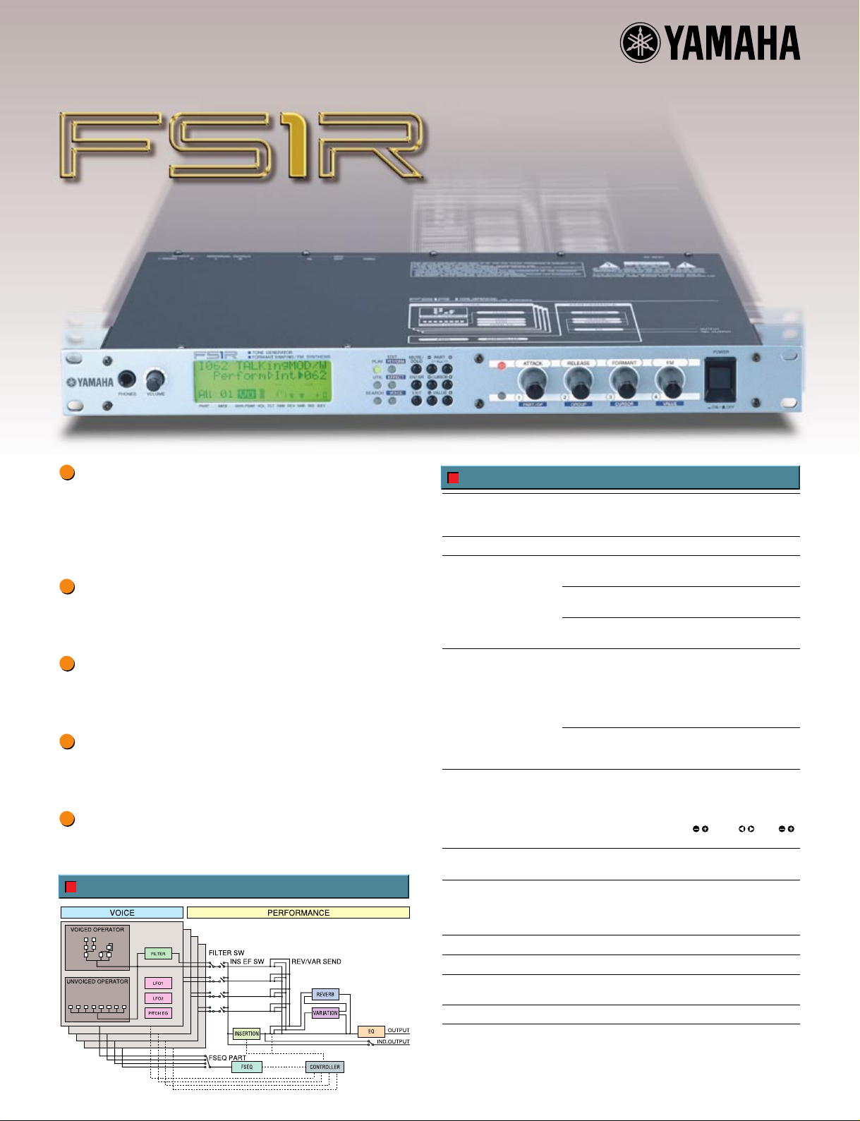
Block Diagram
Specifications
Tone Generation System Tone Generators Formant Shaping / FM Synthesis
DEMO Songs 15
Number of Voices Performance
Components Performance
Controls POWER Switch
Display LCD (Backlit)
Terminals Front panel Phones
Dimensions 480(W) x 235(D) x 44(H) mm
Weight 2.6Kg
Power Consumption USA 120V (60Hz) 12.0 Watts
Included Accessories Owner's Manual x 1, Data List x 1, AC Power Cord x 1
Descriptions and photographs in this brochure are for information purposes only,
and specifications are subject to change without notice.
Multi-Timbres 4 Parts (16 MIDI Channel Multi-Timbre)
Polyphony 32 notes (DVA)
Preset 384 (128 x 3 banks), Internal 128
Voice
Preset 1408 (128 x 11 banks), Internal 128 / 64 (Internal Fseq)
Fseq (Formant Sequence)
Preset 90, Internal 6 (max)
4 Parts (4 Voices), Fseq (Formant Sequence),
Voice Controller (Source / Destination Assignable Matrix)
Effects
Reverb 16 types, Variation 28 types,
Insertion 40 types, Equalizer
Voice
16 Operators (Voiced x 8, Unvoiced x 8), 88 Algorithms, LFO1,
LFO2, Dynamic Filter, Pitch EG
Main Volume x 1
Sound Control Knob x 4
Mode x 6 (PLAY, EDIT [PERFORM], EDIT [EFFECT], EDIT [VOICE], UTIL, SEARCH)
Data x 9 (MUTE/SOLO, ENTER, EXIT, PART / , CURSOR / , VALUE / )
Knob Select x 2 (ATTACK, RELEASE, FORMANT, FM / KN1-4 )
LED Mode x 6 Green, Knob Select x 2 Red
Rear panel Output L(MONO), R
Europe 240V (50Hz) 12.0 Watts
(Absolute / Relative)
Individual Out L, R
MIDI IN/OUT/THRU
Page 3

SPECIAL MESSAGE SECTION
This product utilizes batteries or an external power supply (adapter). DO
NOT connect this product to any power supply or adapter other than one
described in the manual, on the name plate, or specifically
recommended by Yamaha.
WARNING:
Do not place this product in a position where anyone could walk on, trip
over ,or roll anything over power or connecting cords of any kind. The use
of an extension cord is not recommended! IF you must use an extension
cord, the minimum wire size for a 25' cord (or less ) is 18 AWG. NOTE:
The smaller the AWG number ,the larger the current handling capacity.
For longer extension cords, consult a local electrician.
This product should be used only with the components supplied or; a
cart, rack, or stand that is recommended by Yamaha. If a cart, etc., is
used, please observe all safety markings and instructions that
accompany the accessory product.
SPECIFICATIONS SUBJECT TO CHANGE:
The information contained in this manual is believed to be correct at the
time of printing. However, Yamaha reserves the right to change or modify
any of the specifications without notice or obligation to update existing
units.
This product, either alone or in combination with an amplifier and
headphones or speaker/s, may be capable of producing sound levels
that could cause permanent hearing loss. DO NOT operate for long
periods of time at a high volume level or at a level that is uncomfortable.
If you experience any hearing loss or ringing in the ears, you should
consult an audiologist.
IMPORTANT: The louder the sound, the shorter the time period before
damage occurs.
Some Yamaha products may have benches and / or accessory mounting
fixtures that are either supplied with the product or as optional
accessories. Some of these items are designed to be dealer assembled
or installed. Please make sure that benches are stable and any optional
fixtures (where applicable) are well secured BEFORE using.
Benches supplied by Yamaha are designed for seating only. No other
uses are recommended.
NOTICE:
Service charges incurred due to a lack of knowledge relating to how a
function or effect works (when the unit is operating as designed) are not
covered by the manufacturer’s warranty, and are therefore the owners
responsibility. Please study this manual carefully and consult your dealer
before requesting service.
ENVIRONMENTAL ISSUES:
Yamaha strives to produce products that are both user safe and
environmentally friendly. We sincerely believe that our products and the
production methods used to produce them, meet these goals. In keeping
with both the letter and the spirit of the law, we want you to be aware of the
following:
Battery Notice:
This product MAY contain a small non-rechargeable battery which (if
applicable) is soldered in place. The average life span of this type of
battery is approximately five years. When replacement becomes
necessary, contact a qualified service representative to perform the
replacement.
This product may also use "household" type batteries. Some of these may
be rechargeable. Make sure that the battery being charged is a
rechargeable type and that the charger is intended for the battery being
charged.
When installing batteries, do not mix batteries with new, or with batteries
of a different type. Batteries MUST be installed correctly. Mismatches or
incorrect installation may result in overheating and battery case rupture.
Warning:
Do not attempt to disassemble, or incinerate any battery. Keep all
batteries away from children. Dispose of used batteries promptly and as
regulated by the laws in your area. Note: Check with any retailer of
household type batteries in your area for battery disposal information.
Disposal Notice:
Should this product become damaged beyond repair, or for some reason
its useful life is considered to be at an end, please observe all local, state,
and federal regulations that relate to the disposal of products that contain
lead, batteries, plastics, etc. If your dealer is unable to assist you, please
contact Yamaha directly.
NAME PLATE LOCATION:
The name plate is located on the bottom of the product. The model
number, serial number, power requirements, etc., are located on this plate.
You should record the model number, serial number, and the date of
purchase in the spaces provided below and retain this manual as a
permanent record of your purchase.
Model
Serial No.
92-BP
Purchase Date
PLEASE KEEP THIS MANUAL
Page 4
PRECAUTIONS
PLEASE READ CAREFULLY BEFORE PROCEEDING
* Please keep these precautions in a safe place for future reference.
WARNING
Always follow the basic precautions listed below to avoid the possibility of serious injury or even death from electrical shock,
short-circuiting, damages, fire or other hazards. These precautions include, but are not limited to, the following:
• Do not open the instrument or attempt to disassemble the internal parts or
modify them in any way. The instrument contains no user-serviceable parts. If
it should appear to be malfunctioning, discontinue use immediately and have
it inspected by qualified Yamaha service personnel.
• Do not expose the instrument to rain, use it near water or in damp or wet
conditions, or place containers on it containing liquids which might spill into
any openings.
• If the AC adaptor cord or plug becomes frayed or damaged, or if there is a
sudden loss of sound during use of the instrument, or if any unusual smells
or smoke should appear to be caused by it, immediately turn off the power
switch, disconnect the adaptor plug from the outlet, and have the instrument
inspected by qualified Yamaha service personnel.
CAUTION
• Use the specified adaptor (PA-3B or equivalent recommended by Yamaha)
only. Using the wrong adaptor can result in damage to the instrument or
overheating.
• Before cleaning the instrument, always remove the electric plug from the
outlet. Never insert or remove an electric plug with wet hands.
• Check the electric plug periodically and remove any dirt or dust which may
have accumulated on it.
Always follow the basic precautions listed below to avoid the possibility of physical injury to you or others, or damage to the
instrument or other property. These precautions include, but are not limited to, the following:
• Do not place the AC adaptor cord near heat sources such as heaters or
radiators, and do not excessively bend or otherwise damage the cord, place
heavy objects on it, or place it in a position where anyone could walk on, trip
over, or roll anything over it.
• When removing the electric plug from the instrument or an outlet, always hold
the plug itself and not the cord.
• Do not connect the instrument to an electrical outlet using a multipleconnector. Doing so can result in lower sound quality, or possibly cause
overheating in the outlet.
• Unplug the AC power adaptor when not using the instrument, or during
electrical storms.
• Before connecting the instrument to other electronic components, turn off the
power for all components. Before turning the power on or off for all
components, set all volume levels to minimum.
• Do not expose the instrument to excessive dust or vibrations, or extreme cold
or heat (such as in direct sunlight, near a heater, or in a car during the day) to
prevent the possibility of panel disfiguration or damage to the internal
components.
• Do not use the instrument near other electrical products such as televisions,
radios, or speakers, since this might cause interference which can affect
proper operation of the other products.
• Do not place the instrument in an unstable position where it might
accidentally fall over.
• Before moving the instrument, remove all connected adaptor and other cables.
• When cleaning the instrument, use a soft, dry cloth. Do not use paint thinners,
solvents, cleaning fluids, or chemical-impregnated wiping cloths. Also, do not
place vinyl, plastic or rubber objects on the instrument, since this might
discolor the panel or keyboard.
• Do not rest your weight on, or place heavy objects on the instrument, and do
not use excessive force on the buttons, switches or connectors.
• Use only the stand/rack specified for the instrument. When attaching the stand
or rack, use the provided screws only. Failure to do so could cause damage to
the internal components or result in the instrument falling over.
• Do not operate the instrument for a long period of time at a high or
uncomfortable volume level, since this can cause permanent hearing loss. If
you experience any hearing loss or ringing in the ears, consult a physician.
■REPLACING THE BACKUP BATTERY
• This instrument contains a non rechargeable internal backup battery which
permits internal data to remain stored even when the power is off. When the
backup battery needs replacing, the message “Battery Low” will display in the
LCD. When this happens, immediately back up your data (using an external
device such as the floppy disk-based Yamaha MIDI Data Filer MDF3), then
have qualified Yamaha service personnel replace the backup battery.
• Do not attempt to replace the backup battery yourself, in order to prevent the
possible serious hazards. Always have qualified Yamaha service personnel
replace the backup battery.
• Never place the backup battery in a location that a child can reach, since a
child might accidentally swallow the battery. If this should happen, consult a
physician immediately.
■SAVING USER DATA
• Save all data to an external device such as the Yamaha MIDI Data Filer MDF3,
in order to help prevent the loss of important data due to a malfunction or user
operating error.
Yamaha cannot be held responsible for damage caused by improper use or
modifications to the instrument, or data that is lost or destroyed.
(3)-3
Always turn the power off when the instrument is not in use.
Page 5

About This Manual
CONTENTS
Congratulations on your purchase of the CS2x Control Synthesizer! And
thank you for choosing Yamaha.
The CS2x introduces a completely new dimension to the enormously
popular CS1x, providing more great sounds, additional SOUND
CONTROL knobs for broader real-time sound sculpting capabilities, plus
other handy features which provide for greater overall operational
convenience and performance flexibility.
This owner’s manual is your personal “hands on” guide to getting the
most from your CS2x — so be sure to keep it in a safe and accessible
place for quick and easy reference whenever you may need it! It is
divided into the following sections:
Getting Started
This section includes everything you need to get to know the CS2x inside and out.
It is divided into four parts: Welcome To The World Of CS2x Control Synthesis,
Setting Up The CS2x, Getting To Know The CS2x, CS2x Quick Tour.
Feature Reference
This section provides descriptions of CS2x features and explanations of operations.
It is in essence a dictionary which you can refer to any time you need to know the
specifics about any given feature. It is organized into the following sections:
Performance Mode, Multi Play Mode, Utility Mode, Store Mode and Factory
Settings.
Appendix
This section provides information related to the digital effects, MIDI, error messages,
troubleshooting and more.
A separate CS2x Control Synthesizer “Data List” book provides tables,
lists and other information related to Preset Performances, normal and
drum voices, MIDI Data Format and more.
Naming Conventions
For maximum ease of understanding, two basic conventions are used
throughout this manual regarding the names of CS2x features, as follows:
• The names of specific buttons located on the panel are placed inside
brackets, e.g. [ARPEGGIO] button, [PERFORMANCE] button, [USER]
button, etc.
Getting Started .................................... 6
Welcome To The World Of CS2x Control Synthesis .......... 6
Main Features.......................................................................... 7
Top Panel ................................................................................ 8
Rear Panel.............................................................................. 10
Setting Up The CS2x........................................................ 11
Basic Connections ................................................................ 11
Powering Up! ........................................................................ 14
Playing The Demo Songs ...................................................... 14
Getting To Know The CS2x .............................................. 15
CS2x Tone Generation .......................................................... 15
Normal Voices And Drum Voices .......................................... 18
Layers .................................................................................... 18
Knob Parameters .................................................................... 19
Panel Edit Parameters ............................................................ 20
Operating Modes .................................................................. 21
CS2x Quick Tour.............................................................. 23
Performance Mode ................................................................ 23
Performance Selection .................................................... 23
Performance Mode Select ........................................ 23
Performance Bank Select .......................................... 23
Performance Number Select .................................... 23
Performance Play ............................................................ 25
Octave Shift Function .............................................. 25
PITCH And MODULATION Wheels ........................ 25
Scenes And SCENE CONTROL Function .................. 25
Performance Editing And Store........................................ 26
SOUND CONTROL Knobs ...................................... 26
The Arpeggiator ........................................................ 27
Panel Edit Matrix ...................................................... 29
User Performance Store ............................................ 30
Multi Play Mode.................................................................... 31
Sequencer Setup ...................................................... 31
Multi Play Mode Select ............................................ 31
Part Assign ................................................................ 32
Part Parameter Edit .................................................... 32
XG Operation .................................................... 33
Multi Play In Performance Mode .......................................... 33
Using The CS2x With XGworks ...................................... 34
• The names of other panel features and terminals are printed in all-caps
just as they appear on the panel, e.g. PITCH wheel, TO HOST terminal,
EFFECT REV SEND parameter, etc.
The illustrations and LCD screens as shown in this owner's manual
are for instructional purposes only, and may be different from the
ones on your instrument.
The company names and product names in this owner's manual are
the trademarks or registered trademarks of their respective
companies.
Feature Reference .............................. 40
Performance Mode.......................................................... 40
Common Edit 1 .................................................................... 43
Common Edit 2 .................................................................... 45
Layer Edit 1............................................................................ 47
Layer Edit 2............................................................................ 50
Layer Edit 3............................................................................ 52
Layer Edit 4............................................................................ 54
Multi Play Mode.............................................................. 57
Utility Mode .................................................................... 61
Store Mode...................................................................... 66
Factory Settings .............................................................. 69
Appendix ............................................ 70
Digital Effects .................................................................. 70
About MIDI .................................................................... 72
Specifications .................................................................. 76
Troubleshooting .............................................................. 77
Error Messages ................................................................ 78
Index .............................................................................. 79
5
Page 6
Getting Started
CONTROL
SYNTHESIZER
Getting Started
Welcome To The World Of CS2x
Control Synthesis
Whether you’re a beginner and the CS2x is your very first professional synth, or you’re a seasoned professional making a living
entertaining the masses — or whether you style yourself as anything in between — you’re sure to find the CS2x to be one of the finest
electronic musical instruments you’ll ever own. It’s certainly one of the most
fun.
It can be said that the CS2x is a sort of
“hands on” interactivity, broad dimensions of sound, an Arpeggiator, and a wealth of real-time control features — and unites it with the
best of modern digital — such as stable pitch, a full 64 notes of polyphony, one-touch setting reconfigurations, a generous 16 MB of
Wave ROM plus lots of storage memory, comprehensive MIDI features, and much, much more.
Another great thing about the CS2x is that there are no pages and pages of hard-to-get-at hidden functions. Literally everything you need
is laid out right before your eyes. And simply a press of a button — or twist of a knob — away. Since all complicated concepts and
frustration factors are eliminated right from the start, the CS2x is quick and easy to learn to operate.
And if you should ever need to use the CS2x as a multitimbral tone generator, you’ll find it the ideal MIDI system component since it’s
designed to accommodate XG and General MIDI System Level 1 (GM) formats with ease. It also lets you set up your own configuration
of multiple timbres using a unique “4-Layer plus 12-Part” system that lets you keep your Performance timbre intact. There’s even a stereo
mini plug input which lets you “mix” the stereo or mono audio signals of an external component such as a sampler or submixer with
the CS2x’s audio output.
All things considered, the CS2x is sweet and simple — but incredibly powerful. Capable of holding its own in literally any music
situation, it’s an exciting world of modern music that you’ll be proud to be a part of.
analog-style digital synth
. It takes the best of traditional analog — such as simplicity of use, natural
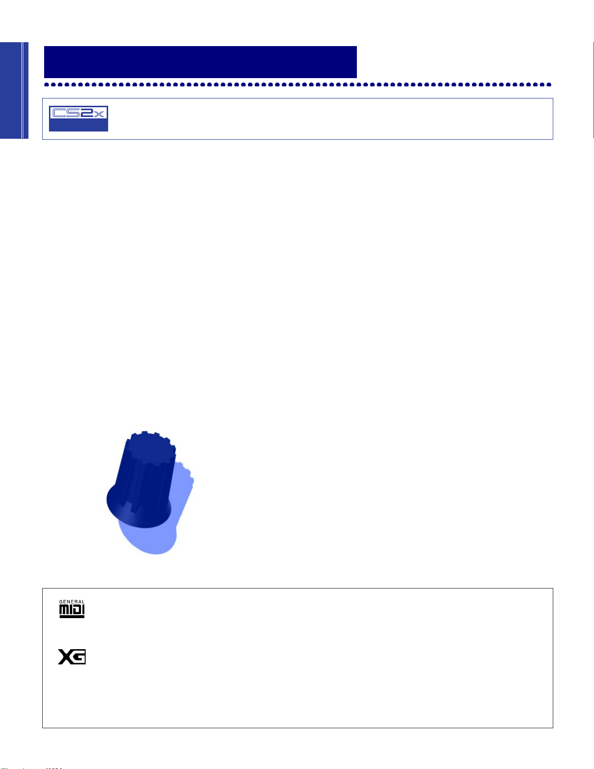
GM System Level 1
“GM System Level 1” is a standard specification that defines the arrangement of voices in a tone generator and its MIDI
functionality, ensuring that data can be played back with substantially the same sounds on any GM-compatible tone generator,
regardless of its manufacturer or model. Tone generators and song data that meet the “GM System Level 1” bear this GM logo.
XG
“XG” is a tone generator format that expands the voice arrangement of the “GM System Level 1” specification to meet the everincreasing demands of today’s computer peripheral environment, providing richer expressive power while maintaining upward
compatibility of data. “XG” greatly expands “GM System Level 1” by defining the ways in which voices are expanded or edited
and the structure and type of effects.
When commercially available song data bearing the XG logo is played back on a tone generator which bears the XG logo, you
will enjoy a full musical experience that includes unlimited expansion voices and effect functions.
6
Page 7

Getting Started
Main Features
The CS2x is designed for maximum real-time control during performance. This makes it the ideal
choice for Dance DJs, Rhythm And Rhyme MCs, Drum & Bass and Techno musicians — and
anyone else whose music thrives on a cutting edge synth sound. It’s also an ideal multitimbral
“module” fit for any type of MIDI system. Following is a list of the CS2x’s main features.
● 16 MB Wave ROM With AWM2 Voices
AWM2 (Advanced Wave Memory 2) voices are comprised of actual digital recordings, or
samples, of real musical instrument and other sounds. Voices available for use include 586
normal voices and 20 drum voices (kits) for GM and XG format applications in Multi Play mode,
plus much more.
● 256 Preset And 256 User Performances
A “Performance” is a complete configuration of a
in sophisticated keyboard and velocity splits) plus digital effects selections, Arpeggiator and
many other parameter settings. Performance mode — the chief operating mode for real-time play
— has 256 great-sounding Preset Performances plus 256 User Performances for storing your
own.
● 8 Real-time Sound Control Knobs And “Scenes”
The SOUND CONTROL knobs give you direct access to key parameters of the currently selected
Performance as you play. Each Performance has two Scene memories, each of which provides
instant recall of specific SOUND CONTROL knob positions. You can use the MODULATION
wheel or a connected Foot Controller to “morph” between the sound of each Scene during
performance.
Layer
(up to 4 voices either stacked or playing
● Arpeggiator With 40 Patterns
The Arpeggiator lets you select from 40 types of arpeggiated chord patterns and 10 timing
subdivisions. Included are Up, Down and Up/Down patterns across one or more octaves, plus
various special patterns including Techno, House, Random, Echo&Pan and more. All Arpeggiator
settings are stored as part of each Performance. The Arpeggiator’s tempo can be controlled by an
external MIDI clock, and the Arpeggiator data can be output via MIDI.
● 3 Programmable Digital Effects Units
The three independent DSP digital effects units — Reverb (12 types), Chorus (14 types) and
Variation (62 types) — can all be used simultaneously.
● Easy Connection To And Use With A Computer
A built-in TO HOST terminal plus HOST SELECT switch permits direct connection to an IBM
PC/AT or Apple Macintosh computer without the need for any peripheral interface hardware.
Multi Play mode allows for multitimbral play of up to 16 different Parts (across 16 MIDI
channels, when using an external sequencer) with 64 notes of available polyphony.
7
Page 8
Getting Started
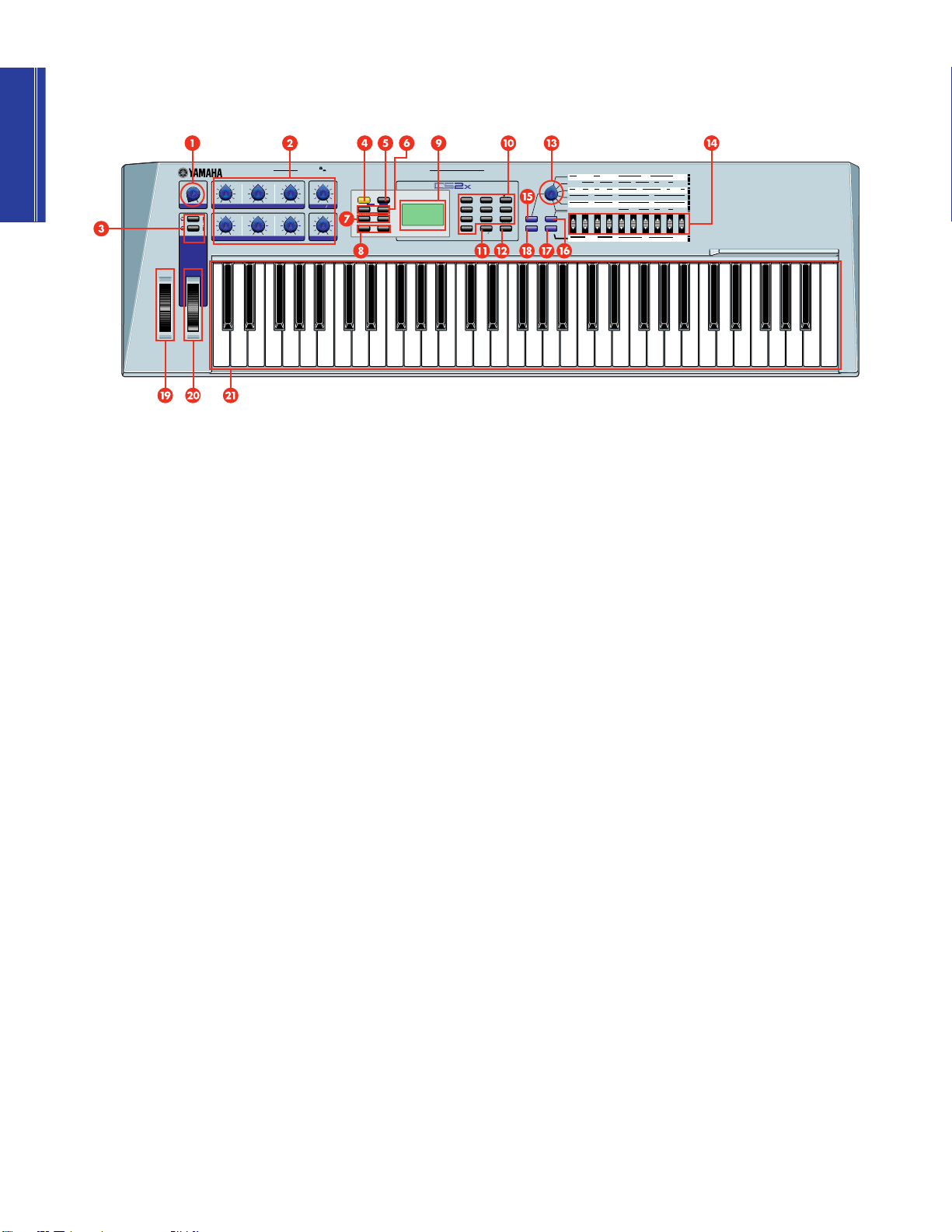
Top Panel
VOLUME
ATTACK
2
MW FC
1
SCENE
PITCH
MODULATION
FOOT
FOOT
FOOT
PHONES
L/MONO
DECAY
CUTOFFCUTOFF LPFHPF
R
OUTPUT
RELEASE DATAASSIGN
RESONANCE
STANDBY
DC IN
VOLUME
CONTROLLER
ON
ARPEGGIO
1
–
–
PART LAYER
PRESET
–
ASSIGN 2
–
SWITCH
HOLD
PROGRAM
SHIFT
OCTAVE
USER
INPUT TO HOST
+
+
+
+
HOST SELECT
PERFORMANCE
PRESET USER ARPEGGIATOR
IN OUT
THRU
MIDI
CONTROL SYNTHESIZER
,
&
VWX
STORE
MULTI
UTILITY
YZ
8
7
7
8
9
9
PQR STU
MNO
6
5
6
4
4
5
JKL
GHI
DEF
3
2
3
2
1
1
ABC
0
0
QUICK PC
PERFORMANCE
SPACE
.,
ENTER
ENTER
–
–
NO
YES
STORE
ARPEGGIATOR
PERFORM
TEMPO
LEVEL
SUB
TYPE
P BEND
RANGE
NOTE
SFT
ATK
TIME
ATK
TIME
BANK
DEMO
MULTI
UTILITY
MASTER
TUNE
REV
DIVIDE
TYPE
MW
FMOD
FMOD
PMOD
CUTOFF
NOTE
TUNE
DETUNE
LIMIT
LIMIT
LIMIT
HIGH
LOW
LOW
AEG
DCY
REL
AMOD PMOD
SUS
TIME
TIME
LEVEL
FEG
REL
DCY
SUS
INIT
TIME
TIME
LEVEL
LEVEL
REV
VOLUME
PROGRAM
PAN
SEND
SYSTEM
KBD
VEL
VEL
TRANS
FIX
CURVE
CH
PERFORM
EFFECT
NAME
CHO
VARI
VARI
VARI
TYPE
PARAM
DATA
TYPE
FC
CUTOFF
VARI
EF
VEL
LIMIT
HIGH
FMOD
ATK
ATK
LEVEL
TIME
EFFECT
VARI
CHO
SEND
SEND
MIDI
DEVICE
RCVCHTRANS
NO
COMMON
PORTA
ASSIGN1
PARAM
SWITCH
TIME
ASSIGN
2
DATAPARAMDEPTHOFFSET
LFO
SPEED
PHASE
WAVE
INIT
LAYER
PEG
DCY
REL
REL
TIME
TIME
LEVEL
POLY
FILTER
REZ
MONO
CUTOFF
ASSIGN
CTRL
BULK
LOCAL
UTILITY
NO
DUMP
1 VOLUME knob
This knob controls the CS2x’s overall audio volume level output from the
PHONES and OUTPUT jacks. Turn it between left-most (minimum) and
right-most (maximum) positions to set the proper listening level whether
using headphones or amplified speakers.
2 SOUND CONTROL knobs
The eight SOUND CONTROL knobs are used for real-time control and
edit of various tone generator parameters. Turning a knob to the left or
right will offset its specified parameter values accordingly (left for
negative values, right for positive values). Each knob has a detented
center stop position which represents the original value of the parameter.
(page 19.)
3 [SCENE] buttons
Each of the CS2x’s 512 Performances has two “Scene” memories in which
are stored the specific positions of the eight SOUND CONTROL knobs,
giving you the capability of slight or even radical sound reshaping at the
press of a [SCENE] button. Simultaneously pressing both [SCENE] buttons
activates the SCENE CONTROL function, which lets you use the
MODULATION wheel or a connected Foot Controller to “sound morph”
between the two Scenes. (page 25.)
4 [ARPEGGIO] button
Pressing this button turns the Arpeggiator on and off. When the
Arpeggiator is on, you can create automatic arpeggiated chords as you
play. You can designate arpeggio type, tempo and timing subdivision
using the panel edit functions. An ARPEGGIATOR SPLIT function lets you
split the keyboard at C3 so the chords you play to the left of the split point
will create arpeggiated chords and everything from the split point and
above will play as normal. An ARPEGGIATOR HOLD function will cause
arpeggiated chords to continue playing even after you release the keys.
(page 27.)
5 [SHIFT] button
This button has three functions. (1) Holding [SHIFT] and pressing
OCTAVE [-]/[+] transposes the octave of a Performance or voice up or
down (page 25). (2) Holding [SHIFT] and pressing [ARPEGGIO] turns the
ARPEGGIATOR HOLD function on and off (page 27). (3) Holding [SHIFT]
and pressing ARPEGGIATOR TYPE [UP/DOWN] (in Performance Edit
mode when the Arpeggiator Type screen is displayed) turns the
ARPEGGIATOR SPLIT function on and off (page 27).
6 PART/LAYER/OCTAVE [-]/[+]
buttons
These two buttons have three functions. (1) In Performance mode you can
use them to select one of the four Layer voices (page 29). (2) In Multi Play
mode you can use them to select one of the 16 Parts (page 32). (3) When
used in conjunction with the [SHIFT] button you can use them to
transpose the octave of the Performance or voice up or down (page 25).
7 [PRESET] and [USER]
Performance buttons
Pressing one of these buttons lets you access a Preset or User
Performance bank in Performance Play mode. Each time you press
[PRESET] or [USER] toggles between P1 and P2 or U1 and U2 banks,
respectively. Each bank contains 128 Performances, making a total of 512
available. (page 23.)
8 PROGRAM [-]/[+] buttons
Each time you press one of these buttons lets you step up ([+]) or down
([-]) through each consecutive Performance (in Performance mode) or
voice (in Multi Play mode). Holding either switch lets you continuously
“scroll” through the list of programs.
9 LCD
The backlit LCD screen displays various types of information to indicate
the current operating status of the CS2x, depending on which mode or
particular function is selected.
8
Page 9

Getting Started
) NUMERIC KEYPAD
The NUMERIC KEYPAD is used in conjunction with the [ENTER/YES] and
[-/NO/QUICK PC] buttons and has several functions. In Performance
mode or Multi Play mode you can use it to select a specific Performance
or voice program number (page 24) as well as for selecting a program
number when the QUICK PROGRAM CHANGE function is active (page
41). In Edit mode you can use it to input positive or negative numeric data
values (page 42) or to select characters when naming a User Performance
(page 45).
! [-/NO/QUICK PC] button
This button has three functions. (1) As a [-] button you can use it to enter
negative data values in Edit mode (page 42). (2) As a [NO] button you can
use it to cancel a store operation if you change your mind (page 66). (3)
As a [QUICK PC] button you can use it to activate the QUICK PROGRAM
CHANGE function (page 41).
@ [ENTER/YES] button
This button is used as an [ENTER] button in conjunction with the
NUMERIC KEYPAD in order to enter a specific program number in Play
mode (page 24) or data value in Edit mode (page 42). It is used as a [YES]
button to confirm store operations (page 66).
# EDIT PARAMETER ROTARY
switch
In Performance mode this six-position switch lets you select one of the
two COMMON or four LAYER menus of parameters (page 41). In Multi
Play mode only the bottom menu of parameters are available, regardless
of the current position of the switch (page 57).
$ Parameter Value [UP/DOWN]
buttons
Used for accessing and editing specific panel parameters and settings,
each of these ten buttons corresponds to a parameter name printed on the
panel above or below a given [UP/DOWN] button. Press it once to enter
Edit mode and display the parameter screen in the LCD. Press the [▲]
area to increase and the [▼] area to decrease values. Holding down
either area will continuously scroll through available settings. In
Performance Edit mode, the position of the EDIT PARAMETER ROTARY
switch determines which COMMON or LAYER parameter is available for
each button. In Multi Part Edit mode, only the parameters printed directly
above the buttons are available. In Utility mode, only the parameters
printed directly below the buttons are available.
^ [MULTI] button
Pressing this button activates Multi Play mode, which lets you select and
play any of the 586 XG voices, as well as designate up to 16 Parts for
multitimbral play (when using an external sequencer). Parameters which
can be edited in Multi Play Edit mode are printed in a row directly above
the Parameter Value [UP/DOWN] buttons. (page 31.)
DEMO function
Pressing [PERFORMANCE] and [MULTI] simultaneously activates
the factory-programmed demonstration songs (page 14).
& [UTILITY] button
Pressing this button activates Utility mode, which lets you access those
“system” parameters that affect the CS2x as a whole, including MASTER
TUNE, MIDI TRANSMIT and RECEIVE CHANNEL numbers, keyboard
LOCAL on/off setting, etc., as printed directly below each Parameter
Value [UP/DOWN] button (page 61).
* [STORE] button
This button is used when performing User Performance, Scene and Multi
Store operations (page 66).
( PITCH wheel
This controller lets you bend the pitch up or down as you play. It is springloaded to automatically return to center position when you let go of it. In
Performance mode you can determine the extent of pitch change using
the PITCH BEND RANGE edit function (page 45).
º MODULATION wheel
This controller lets you apply or set a designated amount of vibrato or
tremolo as you play. You can also set it to affect filter cutoff, filter
modulation, and pitch modulation (page 46) as well as other controllable
parameters (page 64). When the SCENE CONTROL function is active it
can be used to “morph” the sound in real-time between the two Scenes.
¡ Keyboard
The 61-key touch-sensitive keyboard features Initial Touch (velocity)
control.
% [PERFORMANCE] button
Pressing this button activates Performance mode, which lets you select
any of the Preset or User Performances, use the SOUND CONTROL
knobs and SCENE functions, as well as activate the Arpeggiator and
COMMON and LAYER edit parameters. Press [PERFORMANCE] to enter
Performance mode from another mode, or to exit Edit mode and redisplay
the Performance Program Select screen after performing a panel edit
operation. (page 23.)
9
Page 10
Getting Started
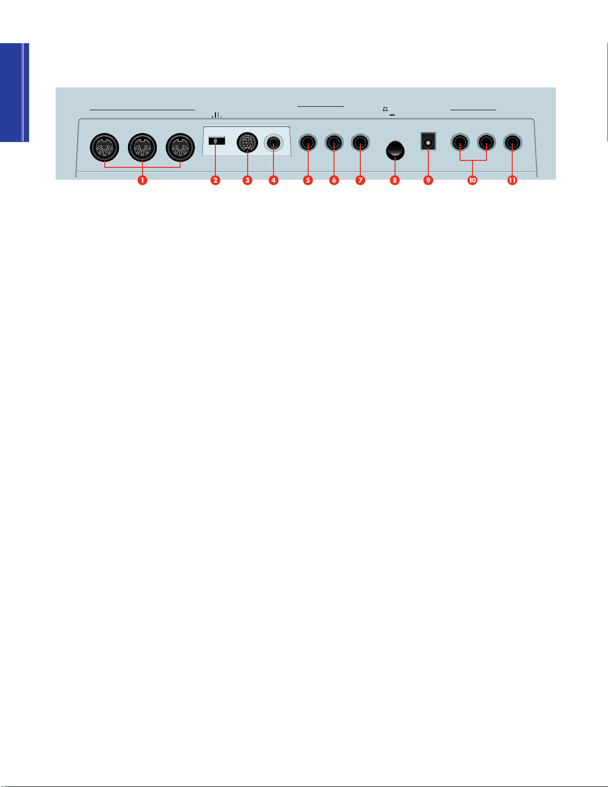
Rear Panel
THRU
MIDI
HOST SELECT
2 PC-1
PC-
INOUT
MIDI Mac
TO HOST
INPUT
1 MIDI terminals
The MIDI terminals let you connect external MIDI devices such as a
sampler, drum machine, sequencer, or computer using MIDI cables.
MIDI IN is for input of MIDI note and other performance-related data, as
well as bulk data dumps from another CS2x or MIDI data storage device.
MIDI OUT is for output of MIDI note and other performance-related data,
as well as for bulk data dumps to another CS2x or MIDI data storage
device. MIDI THRU is for “daisy chain” connection of multiple MIDI
instruments, as the MIDI data received at MIDI IN is passed along
unaffected to MIDI THRU. (NOTE: Set HOST SELECT to “MIDI” when
using the MIDI terminals.)
2 HOST SELECT switch
This switch lets you designate the type of host computer, either PC1, PC2,
Mac, or MIDI (page 13). (NOTE: When a host computer is not connected,
set HOST SELECT to “MIDI” for normal MIDI transmission and reception.)
3 TO HOST terminal
This terminal lets you connect the CS2x directly to a host computer which
does not have a MIDI interface (page 13).
ASSIGNABLE
FOOT
SWITCH
FOOT
CONTROLLER
FOOT
VOLUME
STANDBY
ON
OUTPUT
R
IN
DC
L/MONO
PHONES
6 FOOT CONTROLLER jack
By connecting an optional Yamaha FC7 or FC9 foot controller to this jack
you can control filter modulation, filter cutoff, and the Variation effect
(page 12), as well as the Control Change Number (page 64). You can also
use it for “sound morphing” between Scenes when the SCENE CONTROL
function is active (page 25).
7 FOOT VOLUME jack
By connecting an optional Yamaha FC7 or FC9 foot controller to this jack
you can regulate overall volume by foot.
8 STANDBY/ON switch
This switch is for turning the power of the CS2x on and off (page 14).
9 DC IN terminal
This terminal is for connection of the supplied Yamaha PA-3B Power
Adaptor. (CAUTION: Do not attempt to use an AC adaptor other than the
Yamaha PA-3B or equivalent, since the use of an incompatible adaptor
may cause irreparable damage to the CS2x, and may even pose a serious
shock hazard.)
4 INPUT jack
This jack lets you connect an external audio source (such as a sampler,
CD player, etc.) directly to the CS2x using either a stereo or mono mini
plug. The incoming audio signals are combined and output at the CS2x's
OUTPUT terminals, thus eliminating the need for an external mixer. To
) OUTPUT jacks
The stereo OUTPUT jacks let you connect the CS2x to an external stereo
amplifier/speaker system. When using a mono system, use the L/MONO
jack. (page 11.)
control the relative balance of the signals, use the external device's
output volume control and the CS2x's panel edit PERFORM LEVEL
parameter (Performance mode; page 44) or VOLUME parameter (Multi
Play mode, page 59).
! PHONES jack
This jack lets you connect a set of stereo headphones for private listening
(page 11).
5 FOOTSWITCH jack
By connecting an optional Yamaha FC4 or FC5 footswitch to this jack you
can control hold on/off, portamento on/off and other parameters,
determined by the ASSIGN CTRL NO (Assign Control Change Number)
setting in Utility mode (page 64).
10
Page 11
Setting Up The CS2x
CONTROL
SYNTHESIZER
1. STANDBY
3. To electrical outlet
2. DC IN
PHONES
L/MONO
OUTPUT
R
DC
IN
FOOT
VOLUME
FOOT
CONTROLLER
FOOT
SWITCH
ASSIGNABLE
INPUT
TO HOST
HOST SELECT
PC-
2PC-1
MIDI Mac
INOUT
MIDI
THRU
STANDBY
ON
Amp
MIXER
CS2x
Speaker Speaker
Headphones
1 2 3 4 5 6 7 8 9 10 11 12 13 14 15 16 L R
L R INPUT
R OUTPUT
L
R OUTPUTPHONES
L
CONTROL SYNTHESIZER
Getting Started12Getting Started
This section steps you through the basic connections required for integrating the CS2x into everything from a simple
amplification system to a full-blown MIDI music studio. Also included is information about turning on the power and
listening to the preprogrammed “Demo” songs.
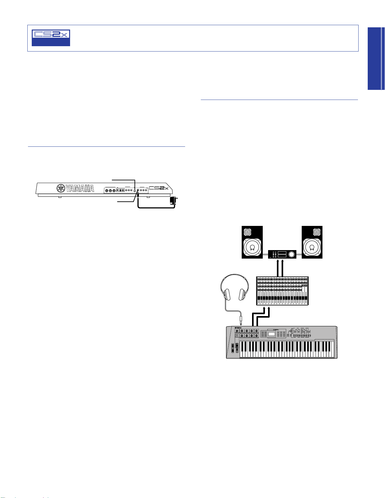
Basic Connections
There are many ways to incorporate the CS2x into a simple or
expanded music system. Below are a few examples to get you
started.
Power Adaptor
The CS2x comes equipped with a Yamaha PA-3B AC adaptor
which supplies DC power to the instrument.
1. Make sure the STANBY/ON switch is in the STANDBY (off)
position.
2. Connect the PA-3B’s DC plug to the CS2x’s DC IN jack.
3. Connect the adaptor’s AC plug to the nearest electrical
outlet.
The CS2x By Itself
At the simplest level, all you need to do to monitor the CS2x is
connect a pair of stereo headphones to the PHONES jack located
on the rear panel.
Or you could connect a pair of amplified speakers (i.e. speakers
with their own built-in amps, like those used with a personal
computer) using two audio cables plugged into the CS2x’s left
and right OUTPUT jacks and each amplified speaker’s input jack.
(For mono use, connect one end of a single audio cable to the
CS2x’s L/MONO jack.)
Or if you want to integrate the CS2x into a larger system with
other instruments and additional audio processing capabilities,
connect it to a mixer, amplifier and stereo monitor system as
shown below.
c
Do not attempt to use an AC adaptor other than the PA-3B.
Use of an incompatible adaptor may result in irreparable
damage to the CS2x, and could even pose a serious shock
hazard.
Be sure to disconnect the power adaptor from the electrical
outlet when the CS2x is not in use.
c
In order to avoid possible damage to the speakers or other
connected electronic equipment, before switching on the
power of any component, make sure the CS2x’s volume level
and the volume levels of the connected equipment are set to
minimum.
11
Page 12
Connecting A Foot
PERFORMANCE
MULTI
DEMO
STORE
UTILITY
UTILITY
MASTER
TUNE
KBD
TRANS
VEL
CURVE
VEL
FIX
SYSTEM
P BEND
RANGE
TYPE
ARPEGGIATOR
TEMPO
PMOD
SUB
DIVIDE
PERFORM
LEVEL
MW
FMOD
CUTOFF
REV
TYPE
CHO
TYPE
VARI
TYPE
VARI
PARAM
PERFORM
NAME
VARI
DATA
ASSIGN1
PARAM
PORTA
SWITCH
TIME
EFFECT
VARI
EF
FC
CUTOFF
FMOD
COMMON
ASSIGN
CTRL
NO
BULK
DUMP
LOCAL
MIDI
DEVICE
NO
RCV
CH
TRANS
CH
BANK
PROGRAM
ATK
TIME
ATK
TIME
DCY
TIME
DCY
TIME
FEG
AEG
SUS
LEVEL
SUS
LEVEL
VOLUME
PAN
REL
TIME
REL
TIME
AMOD PMOD
INIT
LEVEL
ATK
TIME
REV
SEND
EFFECT
CHO
SEND
VARI
SEND
ATK
LEVEL
FMOD
LFO
PEG
DCY
TIME
WAVE
FILTER
CUTOFF
REZ
SPEED
REL
TIME
REL
LEVEL
PHASE
INIT
POLY
MONO
ASSIGN
2
DATAPARAMDEPTHOFFSET
VEL
LIMIT
HIGH
LIMIT
HIGH
LIMIT
LOW
LIMIT
LOW
NOTE
TUNE
NOTE
SFT
DETUNE
LAYER
PHONES
L/MONO
OUTPUT
R
DC
IN
FOOT
VOLUME
FOOT
CONTROLLER
FOOT
SWITCH
ASSIGNABLE
INPUT
TO HOST
HOST SELECT
PC-
2 PC-1
MIDI Mac
INOUT
MIDI
THRU
STANDBY
ON
FC7 or FC9
TONE GENERATOR
TG500
Tone Generator
Sequencer
(QY700)
OUT THRUMIDI IN
CS2x
MIDI OUT IN
MIDI IN
HOST SELECT
PC-2 PC-1
MIDI Mac
CONTROL SYNTHESIZER
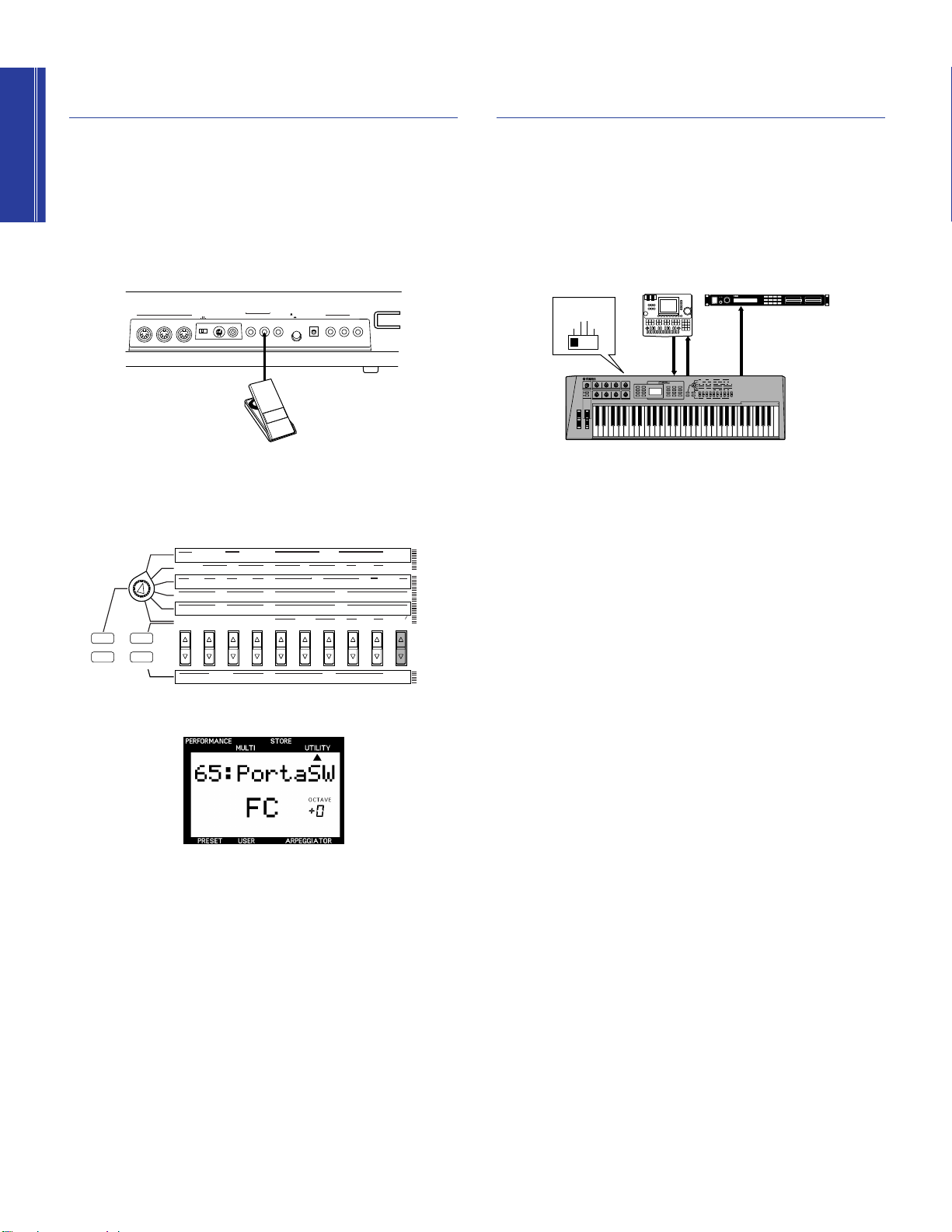
Controller
Connecting External MIDI
Components
In addition to the on-board SOUND CONTROL knobs and other
real-time controllers, you can connect an optional Yamaha FC7
or FC9 foot controller to the CS2x’s FOOT CONTROLLER jack
and assign one of many available parameters to be controlled by
foot.
1. Connect the FC7 or FC9 cable to the CS2x’s FOOT
CONTROLLER jack.
2. Press the [UTILITY] button to enter Utility mode.
3. Press the ASSIGN CTRL NO [UP/DOWN] button once.
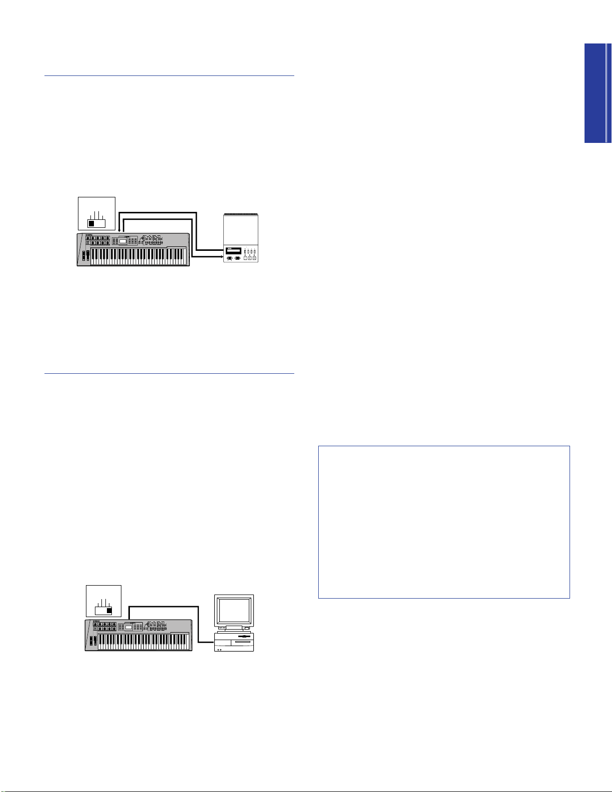
There are many different types of MIDI components available
which you could connect directly to the CS2x using MIDI cables
to take advantage of the CS2x’s multitimbral features and greatly
expand your music production capabilities. Following is an
example of how to connect an external sequencer and additional
tone generator to build up a comprehensive music production
system.
1. Set the CS2x’s rear panel HOST SELECT switch to MIDI.
2. Connect a MIDI cable from the CS2x’s MIDI OUT terminal
to the sequencer’s MIDI IN terminal. Connect another MIDI
cable from the CS2x’s MIDI IN terminal to the sequencer’s
MIDI OUT terminal.
4. Move the foot controller pedal to display “FC” in the LCD.
5. Use the ASSIGN CTRL NO [UP/DOWN] button to select the
Control Change Number and Name of the parameter that
you want to control.
For information about available Control Change Numbers and
Names, see page 65.
n
You can also connect an FC7 or FC9 foot controller to the
CS2x’s FOOT VOLUME jack and assign a parameter to it in
the same way as described above.
3. Connect a MIDI cable from the CS2x’s MIDI THRU terminal
to the tone generator’s MIDI IN terminal
In this monster system, the CS2x is the “master keyboard
controller” used for music note and control data input into the
QY700’s MIDI channel tracks. The QY700 sends the recorded
data directly to the CS2x’s Parts, and — via the MIDI THRU
terminal — to the external tone generator’s Parts.
n
When recording Parts to an external sequencer, you need to
turn the keyboard Local setting to OFF (page 63). For details
about assigning CS2x MIDI transmit and receive channels,
see page 63. For details about assigning MIDI channels and
other settings for the external devices, consult the owner’s
manual of each.
Page 13
Getting Started
Connecting A MIDI Data
TO HOST
Connecting Cable
HOST SELECT
PC-2 PC-1
MIDI Mac
Computer
CS2x
CONTROL SYNTHESIZER
MDR SEO JOB UTIL
MIDI
MMDDFF2
MIDI DATA FILTER
CURSOR
- FILE DATA +
REC PAUSE START/STOP
TEMPO
MDF3 etc.
MIDI IN
MIDI
OUT
MIDI OUT
MIDI IN
HOST SELECT
PC-2 PC-1
MIDI Mac
CS2x
CONTROL SYNTHESIZER
Storage Device
By connecting a MIDI data storage device such as the Yamaha
MDF3 MIDI Data Filer to the CS2x you can save a single User
Performance or all the User Performances and Utility parameters
to floppy disk using MIDI data “Bulk Dump” operations.
This lets you build up complete libraries of Performance and
other data, which you can easily load back into the CS2x. (You
can also play compatible song data on the CS2x directly from the
MDF3 itself, without the need for a sequencer.)
n
The HOST SELECT switch must be set to MIDI. For details
about CS2x Bulk Dump operations, see page 64. (Also refer
to the owner’s manual of the MIDI data storage device for
instructions about sending and receiving data.)
Direct Connection To Macintosh
If you have an Apple Macintosh not equipped with an external
MIDI interface, perform the following operation:
1. Set the HOST SELECT switch to Mac.
2. Connect the cable from the CS2x’s TO HOST terminal to the
Macintosh’s Modem or Printer port.
3. Turn on the power of the host computer, then the CS2x.
4. Launch the music software application, and set up the
software options for operation with the CS2x.
n
You may have to set the Apple MIDI Driver setting as follows:
MIDI Interface Type (Clock) →1MHz. Other settings may
also be required. Refer to the owner’s manual of your
particular music software for more information.
Direct Connection To IBM PC and Clones
If you have an IBM PC/AT or compatible computer not equipped
with an external MIDI interface, perform the following operation:
1. Set the HOST SELECT switch to PC-2.
2. Connect the cable from the CS2x’s TO HOST terminal to one
of the computer’s serial ports, COM 1 or COM 2.
Connecting A Computer
Using the CS2x with a computer permits the widest variety of
options for getting the most from the CS2x’s multitimbral music
production capabilities based on the particular music sequencer
software application you use.
With its built-in host computer interface (TO HOST terminal) the
CS2x is designed for direct connection to an Apple Macintosh,
IBM PC/AT or NEC PC-9800 Series computer — without the need
for a special MIDI interface between the computer and the CS2x.
(If your computer already has a MIDI interface installed, you may
prefer to use it.)
Depending on the computer or interface used, you will need to
use the appropriate MIDI/computer connecting cable (see
following) as well as set the HOST SELECT switch to either PC-1
(NEC PC-9800 Series), PC-2 (IBM PC and clones), Mac
(Macintosh), or MIDI (standard MIDI interface).
3. Turn on the power of the host computer, then the CS2x.
4. Launch the music software application, and set up the
software options for operation with the CS2x.
n
For more information, refer to the owner’s manual of your
particular music software.
MIDI/Computer Connecting Cables
MIDI Standard MIDI cable, maximum length 15 meters.
Mac Apple Macintosh Peripheral cable (M0197), maximum
length 2 meters.
PC-1 8-pin MINI DIN to D-SUB 25-pin cable, maximum length
1.8 meters. (If your PC-1 type computer has a 9-pin serial port,
use the PC-2 type cable.)
PC-2 8-pin MINI DIN to D-SUB 9-pin cable, maximum length
1.8 meters.
13
Page 14

Getting Started
Powering Up!
PERFORMANCE MULTI
DEMO
STORE UTILITY
Playing The Demo
Now that you’ve made all your audio and MIDI connections
properly, you’re ready to switch on the power and get down to
the business of enjoying the CS2x in all its glory! Here’s the basic
procedure:
1. Turn the CS2x VOLUME knob to its minimum position.
2. Press the STANBY/ON switch, located on the rear panel.
After a brief greeting message appears in the LCD, the CS2x
will be ready to play.
3. Gradually turn the VOLUME knob to the right while playing
the keyboard until you achieve a comfortable listening level.
c
In order to avoid possible damage to the speakers or other
connected electronic equipment, always switch on the
power of the CS2x before switching on the power of the
amplified speakers or mixer and amplifier. Likewise, always
switch off the power of the CS2x after switching off the
power of the amplified speakers or mixer and amplifier.
c
Even when the switch is in the “STANDBY” position,
electricity is still flowing to the instrument at a minimum
level. When not using the CS2x for an extended period of
time, be sure to unplug the AC power adaptor from the wall
AC outlet.
Songs
Before you get carried away exploring the many Performances
and other great features of the CS2x, you may want to listen to
the preprogrammed demonstration songs.
The demonstration songs provide dynamic and stunning
examples of just how powerful the CS2x really is. To play the
DEMO, perform the following operation:
1. Hold the [PERFORMANCE] button, then press [MULTI].
2. The word “DEMO” will appear in the LCD, and after a brief
moment the first demonstration song will begin, and will be
immediately followed by the next, and the next, and so on.
3. To stop the Demo at any time, simply press a mode button
such as [PERFORMANCE].
n
When the Demo mode is engaged, you can select a
particular Demo song by pressing a number on the
NUMERIC KEYPAD.
14
Page 15

Getting Started
Getting To Know The CS2x
CONTROL
SYNTHESIZER
CS2x Tone
Generation
The CS2x Control Synthesizer — and the way it creates its myriad
sounds — is a natural evolution of the various types of popular
synthesizers that have come before it over the past several
decades.
It all started with the popular analog “voltage controlled”
synthesizers used on the hit recordings of the 1960s and ‘70s.
Although they were far from perfect — suffering from lack of
storage, unstable tuning and limited polyphony — they had
knobs that were pretty easy to use and even to this day are known
as the “vintage” synths now sought after by the world’s top dance
music artists.
Then came the digital breakthroughs of the early 1980s —
personified by Yamaha’s DX7 which dispensed with knobs
altogether and introduced the world to practical polyphonic
synthesis. With its voice storage, MIDI and other capabilities it
literally redefined what a synthesizer was all about, although to
many it was a bit difficult to program.
Next came digital sampling — a field in which Yamaha has also
been at the forefront with its
technology — which nothing less than revolutionized popular
music itself and is still immensely popular to this day.
Advanced Wave Memory
(AWM)
Generating Sounds Electronically
For the sake of the uninitiated, let’s take a look at some basic facts
regarding the nature of sounds and how they are generated
electronically. There are three basic elements which make up any
type of sound, whether acoustically oriented or electronically
generated, as follows:
PITCH, or how low or high a sound is;
TONE, or what a sound’s overall timbre, or quality is like;
AMPLITUDE, or how loud a sound’s volume level is.
In the simplest terms, acoustic musical instruments are
specifically designed and painstakingly built to produce precise
sound characteristics over a determined range when played. This
is why a violin always sounds like a violin, a piano always
sounds like a piano, and a flute always sounds like a flute. A
musician’s playing techniques are also extremely important.
For example, a violinist will “scrape” the bow across the string at
a certain intensity to generate violin sound waves at a certain
volume level (amplitude) and produce low or high notes based
on fingering positions (pitch). The vibrating strings and resonating
wood, as well as the playing style and techniques of the
musician, will determine the overall quality of the violin’s timbre
(tone).
Now comes the CS2x with its convenient digital features plus
knobs and other analog-style functions. Combining the best of
both analog and digital worlds, the CS2x is truly a unique — and
completely modern — electronic instrument that’s as easy to
understand and operate as it is fun and intuitive to play.
What this means in practical terms is that the CS2x provides you
with hundreds of great sampled sounds, or “voices” built right in,
the detailed characteristics of which you can manipulate in realtime as you play using the eight SOUND CONTROL knobs and
other handy controllers. These and many other parameter editing
functions let you quickly and easily customize as many sound
setups that you may need for a tune, and then store them in
“Performance” and “Scene” memories for instant recall at the
touch of a button!
15
Page 16
Getting Started
Oscillators, Filters, Amplifiers And Envelope Generators
AmplifierFilterOscillator
Controls Volume Characteristics Over TimeControls Pitch Characteristics Over Time Controls Tone Characteristics Over Time
Amplitude Envelope Generator
Pitch Envelope Generator Filter Envelope Generator
Synthesizers rely on three distinct electronic components to imitate or “synthesize” the soundwaves of musical instrument voices as well
as create entirely new sounds. In traditional analog synthesis the fundamental source sound pitch is generated by an
is created by a
filter
, and its volume is determined by an
amplifier
.
oscillator
, its tone
Another key component is known as the
envelope generator
(EG). An envelope generator determines how the pitch, filter or amplifier
behaves over time to create greater dynamics. The EG affects specific sound levels over time through “ADSR” stages, or Attack (initial
fade-in time), Decay (the time it takes to reach the Sustain level), Sustain (the specified level while a key is held) and Release (the time
it takes for the level to reach zero after releasing the key).
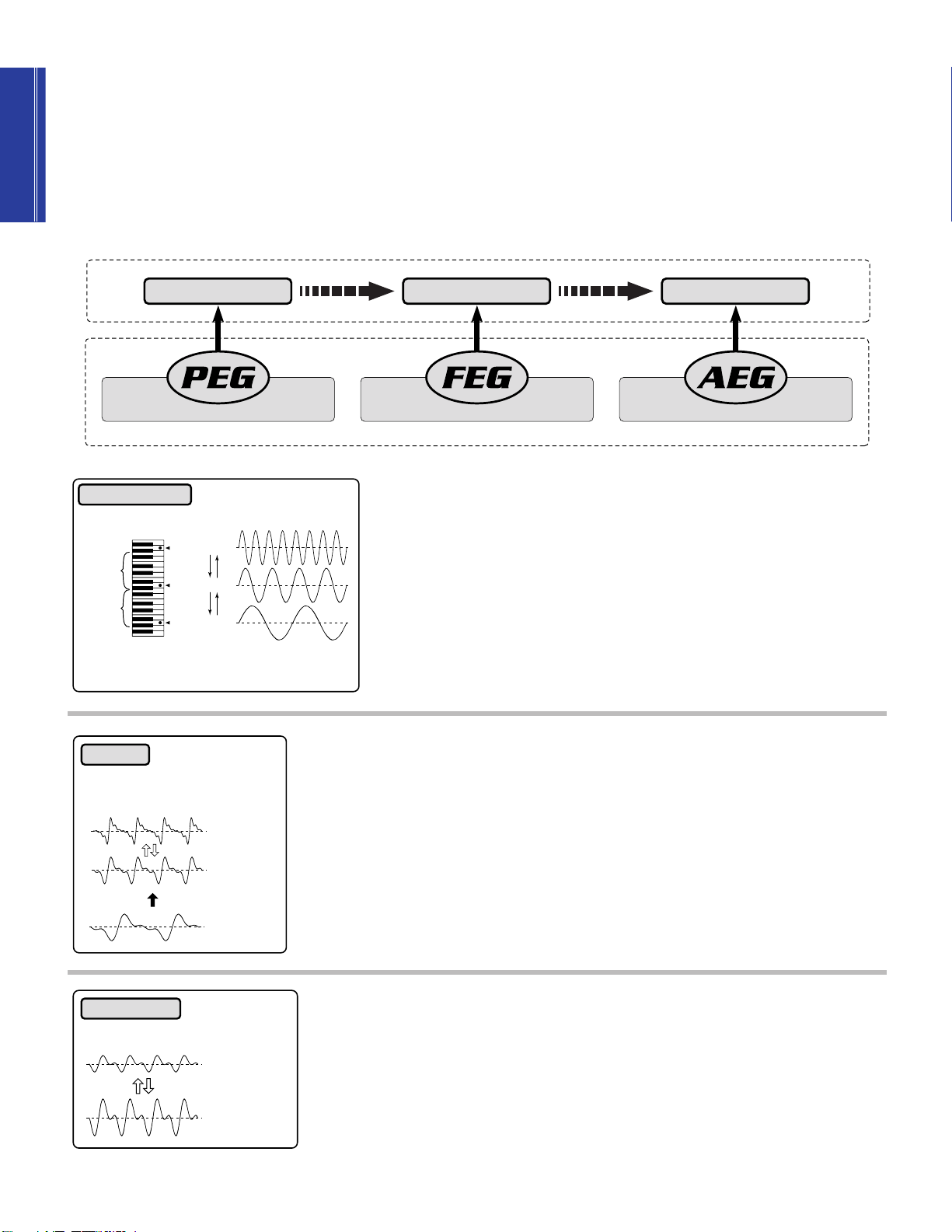
OSCILLATOR
Frequencies generate the pitch of specific notes
A4 = 880Hz
1 octave
1 octave
* **
A3 = 440Hz
* **
A2 = 220Hz
The oscillator generates sound wave vibrations at controllable speeds, or
(“cycles per second”) to create pitch. A frequency
cycle
is the time it takes for a sound
wave to go from its zero position (represented by the dotted line in the illustration) to
its point of maximum peak (top), back past zero to its maximum trough (bottom), and
finally back to zero. Frequencies are measured in “Hertz” (Hz), where one cycle per
second is equal to one Hz. Synthesizer oscillators usually offer a range of frequencies
between 20 Hz and 20kHz to generate pitch, which is the range of the “audio
spectrum” that most human beings can hear. They also usually offer various types of
sound waveforms with specific shapes and sound characteristics, such as sine,
frequencies
sawtooth, square, pulse and other waves. Oscillators in the CS2x, unlike traditional
1 cycle per second = 1 Hz
* Doubling the frequency increases pitch by one octave
** Halving the frequency decreases pitch by one octave
analog synthesizers, consist of complete AWM2-type sampled “waveforms” with
stable tuning. You can use the PEG (Pitch Envelope Generator) parameters to directly
control the critical pitch characteristics over time.
Musical instrument sounds are made up of the basic tone that we clearly distinguish
FILTER
The number of harmonics can be
increased and decreased
Harmonics
Basic tone
More harmonics
creates a
brighter tone
Less harmonics
creates a
darker tone
with our ears plus additional harmonics, or overtones which exist at each octave
above the basic tone, but that we cannot distinctly hear. The filter provides control
over these harmonics. By manipulating the filter’s cutoff frequency (which determines
where to delete, or cut off the overtones) and resonance settings, you can thus
determine the tone. With the CS2x, you can use the FEG (Filter Envelope Generator)
parameters to directly control the critical tone characteristics over time, as well as
control cutoff, resonance and other parameters to shape the tone.
An amplifier controls the volume of the tone. The CS2x has an AEG (Amplitude
AMPLIFIER
A tone’s volume level can be controlled
over time
Lower volume level
Higher volume level
Envelope Generator) which lets you control various volume characteristics over time.
16
Page 17
Getting Started
How The CS2x Generates Sound
AMPLIFIERS EFFECTSFILTERS
AWM2 WAVEFORM
CONTROLLER
OSCILLATORS
AWM2 VOICE
LFO
VOLUME
LEVEL
TIME
ATTACK TIME
( ATK TIME )
DECAY TIME
( DCY TIME )
SUSTAIN LEVEL
( SUS LEVEL )
RELEASE TIME
( REl TIME )
KEY ON
KEY OFF
LEVEL
ATTACK LEVEL
( ATK LEVEL )
RELEASE LEVEL
( REL LEVEL )
TIME
BASIC KEY
PLAYED
INITIAL LEVEL
( INIT LEVEL )
ATTACK TIME
( ATK TIME )
DECAY TIME
( DCY TIME )
RELEASE TIME
( REL TIME )
PITCH
KEY ON
KEY OFF
RELEASE TIME
( REL TIME )
CUT OFF
FREQUENCY
TIME
LEVEL
ATTACK TIME
( ATK TIME )
DECAY TIME
( DCY TIME )
KEY ON
KEY OFF
SUSTAIN LEVEL
(SUS LEVEL)
1
2
3 4
5
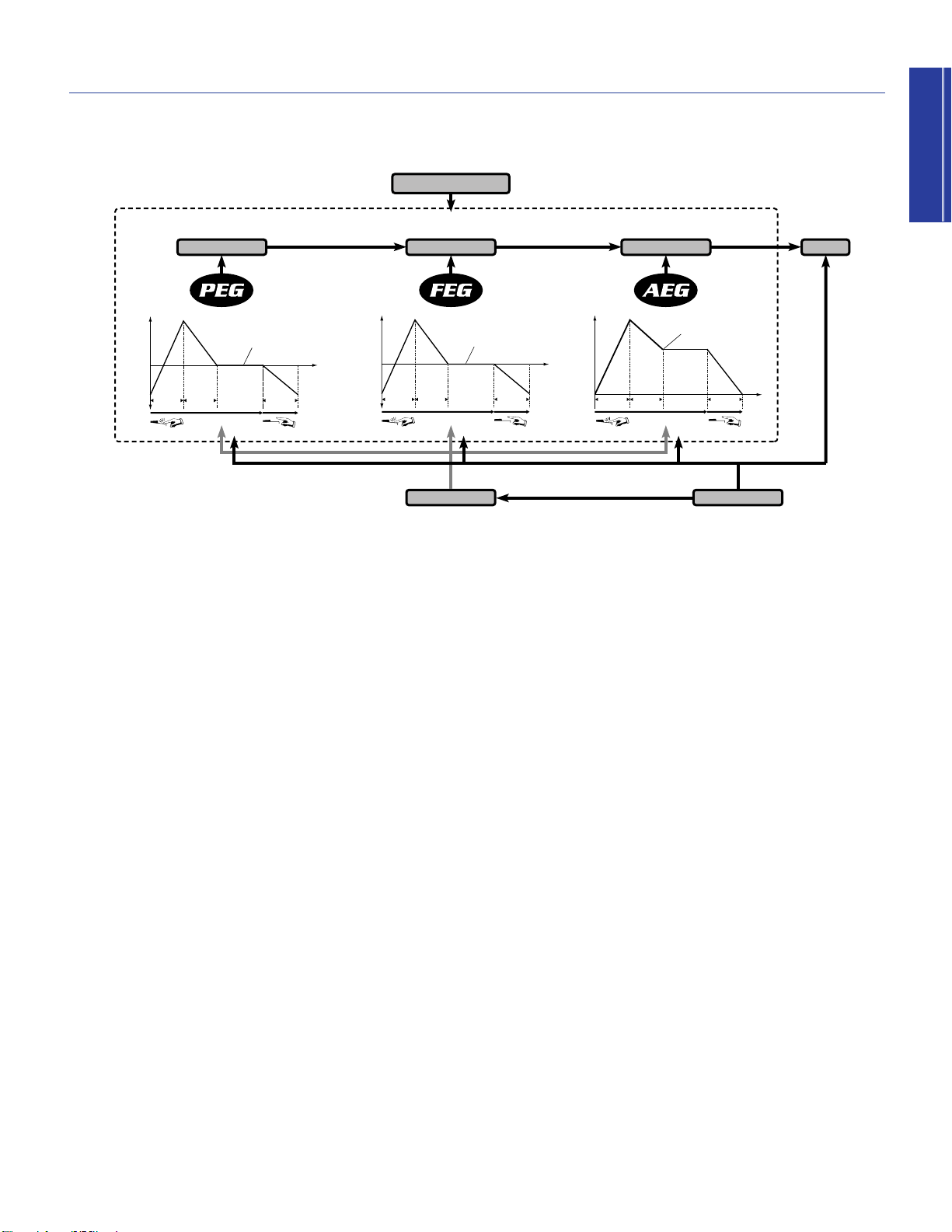
The diagram and accompanying information below explains the CS2x’s tone generation architecture and the key components which
go into making up an AWM2 voice, as well as the types of controls and parameters which you can apply to the voice.
1 AWM2 Waveform The fundamental source of
the CS2x’s sound is the sampled AWM2
waveform. There are hundreds preprogrammed
in ROM which are used by the Performances.
SUS LEVEL (Sustain Level) sets the Sustain
Level; the cutoff frequency will be
maintained at this level for as long as the
key is held.
REL TIME (Release Time) determines the
time it takes for the cutoff frequency to
2 AWM2 VOICE The AWM2 waveform
combines with the oscillator, filter and amplifier
reach the level preset for each voice after
the key has been released.
to make up a CS2x voice.
● AEG The Amplitude Envelope Generator
● PEG The Pitch Envelope Generator controls
how the pitch changes over time.
INIT LEVEL (Initial Level) sets the initial pitch
level when a key is played.
ATK TIME (Attack Time) determines the time
required for a sound to reach its Attack Level
after a note is played.
ATK LEVEL (Attack Level) sets the initially
targeted level after a note is played.
DCY TIME (Decay Time) determines the time
required for a sound to reach its basic pitch
from the Attack Level while the key is held.
REL TIME (Release Time) determines the time
it takes for the basic pitch to reach the
Release Level after the key has been
released.
REL LEVEL (Release Level) sets the final
targeted level after the key is released.
● FEG The Filter Envelope Generator controls
how the timbre changes over time.
ATK TIME (Attack Time) determines the time
required for a sound to reach its maximum
cutoff frequency level when a note is played.
DCY TIME (Decay Time) determines the time
required for a sound to reach its Sustain
Level from the maximum level while the key
is held.
controls how the volume changes over time.
ATK TIME (Attack Time) determines the time
required for a sound to reach its maximum
volume level when a note is played.
DCY TIME (Decay Time) determines the
time required for a sound to reach its
Sustain Level from the maximum volume
level while the key is held.
SUS LEVEL (Sustain Level) sets the Sustain
Level; the volume will be maintained at this
level for as long as the key is held.
REL TIME (Release Time) determines the
time it takes for a sound to sustain after the
key has been released.
3 LFO The Low Frequency Oscillator generates
low frequency signals which can be used to
modulate the PEG, FEG and AEG.
● PMOD The LFO can apply Pitch
Modulation to the PEG to create vibrato
effects.
● FMOD The LFO can apply Filter Modulation
to the FEG to create wah-wah types of
effects.
● AMOD The LFO can apply Amplitude
Modulation to the AEG to create tremolo
effects.
4 CONTROLLER You can use several types of
controllers to manipulate various parameters in
realtime.
● MW Use the Modulation Wheel to control
PMOD, FMOD, and Filter Cutoff.
● FC Use the Foot Controller to control
FMOD, Filter Cutoff, and Variation Effect.
● SOUND CONTROL KNOBS The eight
sound SOUND CONTROL knobs let you
control AEG Attack, Decay and Release
Times, HPF and LPF Cutoffs, LPF Resonance,
and more (page 19). The ASSIGN 1/DATA
and ASSIGN 2 knobs can be specified to
control one of many types of available
parameters (see the lists on pages 47 and
65).
5 EFFECTS Available effects which can be
applied to a voice depend on whether the CS2x
is in Performance mode or Multi Play mode.
17
Page 18

Getting Started
Normal Voices And
Drum Voices
As explained in the previous section, an AWM2 waveform is the
fundamental source of a CS2x “voice”, which also consists of
oscillator, filter and amplifier settings.
The CS2x has two types of voices in memory which are preset at
the factory:
typical pitched musical instrument voice such as piano, strings,
brass, etc. A drum voice is an entire drum kit which has various
bass, snare, toms, hi-hat, cymbals and other acoustic or
electronic percussion and effects sounds that are “mapped” to
specific keys on the keyboard.
normal
voices and
drum
voices. A normal voice is a
Layers
Although the individual AWM2 voices sound great in their own
right, the CS2x lets you use up to four of them at the same time
to create a
these to sound simultaneously — to build up an incredibly rich
sonic tapestry — or you can “map” specific Layer voices to
various note and velocity zones across the keyboard to create
amazingly complex sound textures that behave in a variety of
ways depending on which notes you play or how hard you strike
the keys.
Layer
in Performance mode. You can designate all of
The best way to find out just how exceptional Layers can be is to
step through the 256 Preset Performances programmed at the
factory. As you do so, you might find it helpful to take a look at
the separate “Data List” book’s Preset Performance list which
contains information about how may Layer voices are used and
other chief settings for each Performance.
In Performance mode there are a considerable number of
COMMON and LAYER parameters available that you can control
or edit which affect all Layers equally or individual Layer voices,
respectively (see following).
n
For more information, see pages 41 and 58. Also see the
separate “Data List” book for voices available for use in
Performances.
18
Page 19

Getting Started
FREQUENCY
VOLUME
CUTOFF FREQUENCY
RESONANCE
FREQUENCY
VOLUME
CUTOFF FREQUENCY
FREQUENCIES CUT
FREQUENCIES PASSED
FREQUENCY
VOLUME
CUTOFF FREQUENCY
FREQUENCIES
CUT
FREQUENCIES PASSED
Key On Key Off
ATK TIME REL TIMEDCY TIME
SUS
LEVEL
TIME
VOLUME
Knob Parameters
ATTACK
DECAY
RELEASE DATAASSIGN
1
ASSIGN 2
RESONANCE
CUTOFFCUTOFF LPFHPF
Knob 1
[ATTACK]
Knob 2
[DECAY]
Knob 3
[RELEASE]
Knob 4
[ASSIGN 1/DATA]
Knob 5
[HPF CUTOFF]
Knob 6
[LPF CUTOFF]
Knob 7
[RESONANCE]
Knob 8
[ASSIGN 2]
111
555 666 777 888
22 333 4442
The eight SOUND CONTROL knobs give you direct access to a variety of important parameters of the Performance. Turning any
SOUND CONTROL knob to the left or right will offset its parameter values accordingly (based on knob positions: left for negative
values, right for positive values). Each SOUND CONTROL knob has a center detent, or stop position which represents the original
value of the parameter.
Attack, Decay & Release
Knobs
These knobs let you control the initial Amplitude
Envelope Generator characteristics of the timbre.
HPF Cutoff, LPF Cutoff &
Resonance Knobs
These knobs let you control the filter settings
which determine the sound quality of the
timbre.
7 [RESONANCE] (Knob 7)
This knob determines the amount of filter
resonance or emphasis of the cutoff frequency of
the low pass filter. Turn it left to produce a
relatively flat response, or right to add overtones
and make the sound more resonant. (page 55.)
5 [HPF CUTOFF] (Knob 5)
This knob determines the cutoff frequency of the
high pass filter. The cutoff is the frequency point
below which other frequencies are deleted, or
filtered out. Turn it left to lower the cutoff point
and fatten the sound, or right to raise it and thin
out the sound.
1 [ATTACK] (Knob 1)
This knob controls the initial AEG attack time of
the voice. Turn it left for a faster attack time, or
right for a slower attack. (page 50.)
8 [ASSIGN 2] (Knob 8)
This knob can be used to control any one of
many parameters which you can assign to it —
including Volume, Note Shift, Pan, Chorus Send,
and others. (page 49.)
2 [DECAY] (Knob 2)
This knob controls the AEG decay time of the
voice. Turn it left for a shorter decay time, or
right for a longer decay. (page 50.)
6 [LPF CUTOFF] (Knob 6)
Edit Mark
This knob determines the cutoff frequency of the
3 [RELEASE] (Knob 3)
This knob controls the AEG release time of the
voice. Turn it left for a shorter release time, or
right for a longer release time. (page 51.)
4 [ASSIGN 1/DATA] (Knob 4)
This knob has two functions. As an ASSIGN 1
knob, you can assign one of many parameters —
including Performance Volume, Arpeggiator
Tempo or Type, Portamento Time, and others —
to control by turning it (page 47). As a DATA
entry knob, you can use it to quickly change the
edit value of the currently selected edit
low pass filter. The cutoff is the frequency point
above which other frequencies are deleted, or
filtered out. Turn it left to lower the cutoff point
and make the sound darker, or right to raise it
and make the sound brighter. (page 55.)
In Performance mode, an edit mark will
appear in the LCD between the
Performance bank and number to
indicate that the original Performance
has been edited.
parameter.
19
Page 20

Panel Edit
Edit Parameter Rotary Switch
Parameter Value [UP/DOWN] Buttons
PERFORMANCE
MULTI
DEMO
STORE
UTILITY
UTILITY
MASTER
TUNE
KBD
TRANS
VEL
CURVE
VEL
FIX
SYSTEM
P BEND
RANGE
TYPE
ARPEGGIATOR
TEMPO
PMOD
SUB
DIVIDE
PERFORM
LEVEL
MW
FMOD
CUTOFF
REV
TYPE
CHO
TYPE
VARI
TYPE
VARI
PARAM
PERFORM
NAME
VARI
DATA
ASSIGN1
PARAM
PORTA
SWITCH
TIME
EFFECT
VARI
EF
FC
CUTOFF
FMOD
COMMON
ASSIGN
CTRL
NO
BULK
DUMP
LOCAL
MIDI
DEVICE
NO
RCV
CH
TRANS
CH
BANK
PROGRAM
ATK
TIME
ATK
TIME
DCY
TIME
DCY
TIME
FEG
AEG
SUS
LEVEL
SUS
LEVEL
VOLUME
PAN
REL
TIME
REL
TIME
AMOD PMOD
INIT
LEVEL
ATK
TIME
REV
SEND
EFFECT
CHO
SEND
VARI
SEND
ATK
LEVEL
FMOD
LFO
PEG
DCY
TIME
WAVE
FILTER
CUTOFF
REZ
SPEED
REL
TIME
REL
LEVEL
PHASE
INIT
POLY
MONO
ASSIGN
2
DATAPARAMDEPTHOFFSET
VEL
LIMIT
HIGH
LIMIT
HIGH
LIMIT
LOW
LIMIT
LOW
NOTE
TUNE
NOTE
SFT
DETUNE
LAYER
Getting Started21Getting Started
Parameters
There are numerous parameters available in the panel edit matrix
of menus. In Performance mode, all you have to do is set the
EDIT PARAMETER ROTARY switch to the menu you want, then
press the [UP/DOWN] button directly below the name of the
parameter you want to edit. In Multi Play or Utility modes, the
position of the EDIT PARAMETER ROTARY switch doesn’t matter
because there is only one menu of parameters available for each.
Simply pressing any [UP/DOWN] button once will activate Edit
mode and display the name of the corresponding parameter in
the LCD screen, along with the current setting. There are three
ways to change the parameter value setting:
Following is a description of the types of parameters available for
editing:
COMMON Available in Performance mode only, the COMMON
parameters in the Common Edit 1 and 2 menus apply to the
entire currently selected Performance. Except for the PORTA
SWITCH setting, it doesn’t matter which Layer is currently
selected, since common parameters apply to all Layer voices
equally. Changes to COMMON parameter settings will remain in
effect as long as the current Performance is selected, but will be
lost if you select a different Performance before performing a
Performance store operation. (page 43.)
LAYER Available in Performance mode only, the LAYER
parameters in the Layer Edit 1, 2, 3 and 4 menus affect only the
currently selected Layer of the currently selected Performance.
Changes to LAYER parameter settings will remain in effect as long
as the current Performance is selected, but will be lost if you
select a different Performance before executing a Performance
store operation. (page 47.)
MULTI Available in Multi Play mode only, the MULTI parameters
include voice, effect, and others which apply to the currently
selected Part. There is memory space for a single set of MULTI
parameter settings. Changes to the MULTI parameter settings will
remain in effect as long as you remain in Multi mode, but will be
lost if you switch into Performance mode before performing a
Multi store operation. (page 58.)
1. Press or hold the [▲] area of the [UP/DOWN] button to
increase values, or the [▼] area to decrease values.
2. Enter the number of the value you want using the NUMERIC
KEYPAD, followed by [ENTER] (for negative values, press [–]
before entering the number).
3. Turn the ASSING 1/DATA knob left or right to change the
values when the knob is designated as a DATA ENTRY
function.
UTILITY Available in Utility mode only, the UTILITY parameters
consist of system, MIDI and type of data assignment (for the
SOUND CONTROL knobs) which affect the CS2x as a whole.
These settings will remain in effect regardless of whether you
switch to Performance or Multi Play mode. (page 61.)
20
Page 21
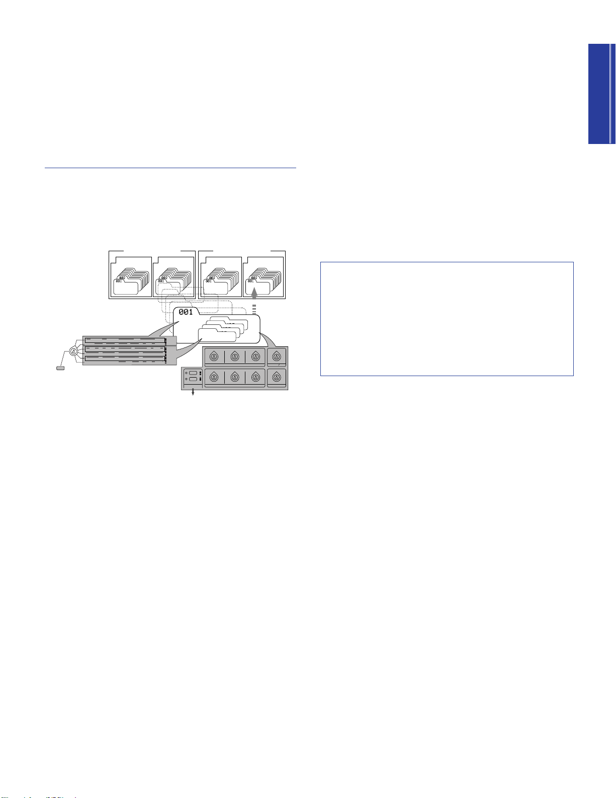
Operating Modes
II: 128 PerformanceI: 128 Performance
Preset Bank
(256 Performance)
II: 128 PerformanceI: 128 Performance
User Bank
(256 Performance)
Performance
Layer 4
VOICE
Layer 3
VOICE
Layer 2
VOICE
Layer 1
VOICE
COMMON EDIT
REAL TIME EDIT with
THE SOUND CONTROL KNOBS
STORE IN USER BANK
SAVE AS SCENE 1 or 2
PERFORMANCE
P BEND
RANGE
TYPE
ARPEGGIATOR
TEMPO
PMOD
SUB
DIVIDE
PERFORM
LEVEL
MW
FMOD
CUTOFF
REV
TYPE
CHO
TYPE
VARI
TYPE
VARI
PARAM
PERFORM
NAME
VARI
DATA
ASSIGN1
PARAM
PORTA
SWITCH
TIME
EFFECT
VARI
EF
FC
CUTOFF
FMOD
COMMON
BANK
PROGRAM
ATK
TIME
ATK
TIME
DCY
TIME
DCY
TIME
FEG
AEG
SUS
LEVEL
SUS
LEVEL
VOLUME
PAN
REL
TIME
REL
TIME
AMOD PMOD
INIT
LEVEL
ATK
TIME
REV
SEND
EFFECT
CHO
SEND
VARI
SEND
ATK
LEVEL
FMOD
LFO
PEG
DCY
TIME
WAVE
FILTER
CUTOFF
REZ
SPEED
REL
TIME
REL
LEVEL
PHASE
INIT
POLY
MONO
ASSIGN
2
DATAPARAMDEPTHOFFSET
VEL
LIMIT
HIGH
LIMIT
HIGH
LIMIT
LOW
LIMIT
LOW
NOTE
TUNE
NOTE
SFT
DETUNE
LAYER
LAYER EDIT
ATTACK
DECAY
RELEASE DATAASSIGN
1
ASSIGN 2
RESONANCE
CUTOFFCUT OFF LPFHPF
SCENE
MW FC
2
1
The CS2x has two main operating modes — Performance mode
and Multi Play mode — both of which give you a range of
options for real-time play as well as multitimbral Part play using
an external MIDI sequencer for song production. There are also
Utility and Store modes.
Performance Modes
Performance mode — accessed by pressing the
[PERFORMANCE] button — actually consists of Performance
Play and Performance Edit modes. The diagram below provides
an overview of the overall structure of key Performance mode
components.
Performance Edit Mode
Performance Edit mode is activated when you change a setting
for any of the parameters available in the panel edit menus using
the Parameter Value [UP/DOWN] buttons — which may affect all
Layer voices equally (COMMON menus) or only the currently
selected Layer voice (LAYER menus).
Adjustments you make using the SOUND CONTROL knobs or
[UP/DOWN] buttons will
parameter data values which are preset for each voice. An edit
mark, or reversed type letter “E”, will appear in the LCD to
indicate that a parameter has been changed. When you’re
satisfied with the sound of the Performance, simply store it in any
of the 256 User Performance memories using the Performance
Store operation (page 66), before selecting a different
Performance.
n
For more information about Performance mode, see page 40.
Song Production In Performance
Mode
Although Performance mode is primarily used for real-time
playing, you can also use it for multitimbral operation in order to
take advantage of Arpeggiator, Scene and other Performance
mode-oriented functions not available in Multi Play mode. In
such a case, one of the instrument “Parts” would be comprised of
the Layer voices for the selected Performance. (For more
information, see page 33.)
offset
(add to or subtract from) the
A
Performance
is comprised of up to four “Layers”, or AWM2
voices sounding at the same time — either playing
simultaneously across the length of the keyboard, or playing
independently according to specified key and velocity range
settings — plus a variety of other settings which determine the
behavior of the Arpeggiator, digital effects selection,
characteristics of envelope generators, and much more.
Performance Play Mode
In Performance Play mode you can select from 512 Performances
— 128 of which are available in each of the two Preset
Performance banks and 128 of which are available in each of the
two User Performance banks — and begin playing the keyboard.
As you play you can select one of two available Performance
timbre variations by pressing a SCENE switch, or fade between
(“morph”) the sounds of each Scene in real-time by pressing both
[SCENE] buttons simultaneously (SCENE CONTROL function)
then using the MODULATION wheel or a connected Foot
Controller to precisely determine the relative volumes of each
Scene timbre in relation to each other.
Page 22

Multi Play Mode
Part 1 ~ 16
BANK
PROGRAM
VOLUME
PAN
EFFECT
FILTER (LPF)
POLY/MONO
PART SELECT
STORE 1 ~ 9
Getting Started23Getting Started
Utility Mode
Multi Play mode — accessed by pressing the [MULTI] button —
is primarily used for multitimbral song production and playback
of up to 16 individual instrument “Parts” when an external MIDI
sequencer is connected to the CS2x. The diagram below lists the
available parameters for each Part.
Although you can adjust various parameters in the Multi Part Edit
menu to customize the selected voice, note that Scene,
Arpeggiator and other Performance mode-oriented functions are
not available.
Utility mode lets you modify System, MIDI and controller
assignment parameters which affect both Performance and Multi
Play mode. For more information, see page 61.
Store Mode
Store mode lets you store your own User Performances as well as
Scenes and a Multi setup. For more information, see page 66.
When the edited Multi setup is just the way you want it, simply
perform a Multi Store operation before switching into
Performance mode (page 68).
n
With the GM format MIDI channel 10 is reserved for drum
voices, which means you can select PART 10 to play the
drums.
n
For more information about Multi Play mode, see page 57.
For information about GM and XG, see page 33.
22
Page 23

PERFORMANCE MULTI
DEMO
STORE UTILITY
Performance nameCategory
Bank
P I (P1) : Preset Bank 1
P II (P2) : Preset Bank 2
U I (U1) : User Bank 1
U II (U2) : User Bank 2
Performance (Program) number
ARPEGGIO
HOLD SHIFT
OCTAVE
PART/LAYER/
+
PRESET USER
PROGRAM
+
Subsequent PerformancePrevious Performance
ARPEGGIO
HOLD SHIFT
OCTAVE
PART/LAYER/
+
PRESET USER
PROGRAM
+
CS2x Quick Tour
CONTROL
SYNTHESIZER
This section provides you with a quick guided tour through all the fundamental CS2x operations in Performance mode, such as use of
real-time control, Scene, Arpeggiator, panel edit and Performance Store functions. It also provides information about Multi Play mode
and multitimbral operation, including Multi Play in Performance mode.
Performance Mode
In Performance mode you can select from 256 Preset and 256
User Performances, use the SOUND CONTROL knobs to modify
certain parameters as you play, select Scenes and use the SCENE
CONTROL function for Scene morphing, and edit the values and
settings of specific COMMON and LAYER parameters.
Performance Selection
Following are the basic procedures for selecting CS2x
Performances.
Performance Mode Select
To enter Performance mode, simply press the [PERFORMANCE]
button.
The basic Performance select screen will display in the LCD, with
information about Preset or User bank selection, Performance
name, program number (1 ~ 128) and category code, and more.
Performance Bank Select
Individual Performances are stored in any one of four available
banks. There are two Preset banks with 128 Performances each
and two User banks with 128 Performances each.
To select one of the Preset banks, press [PRESET] once or more.
To select one of the User banks, press [USER] once or more.
Each time you press [PRESET] or [USER] toggles between P1/P2
or U1/U2 banks, respectively. The currently selected bank will
display accordingly in the LCD screen.
Performance Number Select
There are two ways to select one of the 128 program numbers in
each Preset or User Performance bank — by using the
PROGRAM buttons or the NUMERIC KEYPAD.
■ PROGRAM Button Method
One way to select a Performance in the currently selected bank
is as follows:
Press the PROGRAM [+] or [-] button once or more until you
reach the number of the one you want (between 1 and 128).
n
If you hold down the PROGRAM [+] or [-] button you can
continuously scroll up or down through the list.
Page 24

Getting Started
■ NUMERIC KEYPAD Entry Method
VWX
7
YZ'
8
&
*
9
MNO
4
PQR
5
STU
6
DEF
1
GHI
2
JKL
NO/
QUICK PC
YES
3
ABC
0
SPACE
ENTER
VWX
7
YZ'
8
&
*
9
MNO
4
PQR
5
STU
6
DEF
1
GHI
2
JKL
NO/
QUICK PC
YES
3
3
ABC
0
0
SPACE
ENTER
+
Press the buttons
for the desired
Performance
number
NO. LCD Category Name
0 -- Not specified
1 Pf Piano
2 Cp Chromatic Percussion
3 Or Organ
4 Gt Guitar
5 Ba Bass
6 St Strings/Orchestral
7 En Ensemble
8 Br Brass
9 Rd Reed
10 Pi Pipe
11 Ld Synth Lead
12 Pd Synth Pad
13 Fx Synth SFX
14 Et Ethnic
15 Pc Percussive
16 Se Sound Effect
17 Dr Drums
18 Sc Synth Comping
19 Vo Vocal
20 Co Combination
21 Wv Material Wave
22 Sq Sequence
Another way to select a Performance number in the currently
selected bank is by using the NUMERIC KEYPAD. This is
especially handy if you know the precise number of the
Performance you want. Here’s how:
1. Enter the specific number (1 ~ 128). The number will begin
flashing in the LCD.
2. Press [ENTER]. This selects the Performance, so the number
will stop flashing and remain displayed.
Category Codes
Each Performance (or voice in Multi Play mode) has a “Category”
code assigned to it which helps you organize your Performances
and voices by type for easier visual access. The following list
describes each available Category.
n
There’s another way to quickly select a specific Performance
program number within a group of 10 Performances — by
using the Quick Program Change function (page 41).
n
For details about assigning Category codes to User
Performances, see page 45.
24
Page 25

Getting Started
Performance Play
PITCH
Bends the
pitch up
Bends the
pitch down
ARPEGGIO
HOLD SHIFT
OCTAVE
PART/LAYER/
+
PRESET USER
PROGRAM
+
Indicates
transposition
of two
octaves up
Transposes the octave up while holding [SHIFT]
2
MW/FC
1
SCENE
Applies maximum modulation
Applies no modulation
MODULATION
After selecting a performance, you’re ready to start playing the
CS2x! As you do, you’ll want to try out the various control and
other features available in Performance mode. Let’s continue with
our step-by-step tour.
Octave Shift Function
The CS2x’s Octave Shift function is an easy way to transpose the
octave of the Performance up or down by a maximum ±3
octaves. Here’s how:
1. To transpose the octave up, hold [SHIFT] and press OCTAVE
[+] once or more.
2. To transpose the octave down, hold [SHIFT] and press
OCTAVE [-] once or more.
n
The transpose value will also be reflected in the Utility
mode’s KEYBOARD TRANSPOSE function. Note that since
the maximum is ±3 octaves, when you raise or lower the
keyboard transposition in semitones the full three octaves
cannot be achieved by the Octave Shift function.
PITCH And MODULATION Wheels
As you play, you can use the PITCH wheel to bend the pitch up
and down, and the MODULATION wheel to apply varying
degrees of modulation to the tone.
■ Using The MODULATION Wheel
By rolling the MODULATION wheel forward and back you can
apply as much modulation to the tone as you want. The type of
modulation which can be applied is determined by the three MW
parameter settings in the panel edit matrix (page 46).
n
You can also use the MODULATION wheel for controlling
volume, pan and others (page 64), as well as for SCENE
CONTROL, or morphing (page 26).
Scenes And SCENE CONTROL Function
Each Preset and User Performance has two Scene memories
which are in essence “snapshots” of SOUND CONTROL knob
positions (page 26). This gives you two additional sound textures
available at the touch of a button! What’s more, you can activate
the SCENE CONTROL function which lets you “morph” the
sound of one Scene into the sound of the other.
■ Scene Selection
To select Scene 1, press the [SCENE 1] button.
To select Scene 2, press the [SCENE 2] button.
■ Using The PITCH Wheel
By rolling the PITCH wheel forward and back you can bend the
pitch of the tone by the amount as determined by the P BEND
RANGE parameter setting in the panel edit matrix (page 45).
A red LED will light beside the currently selected Scene. To deselect the Scene, press the [SCENE] button again.
25
Page 26
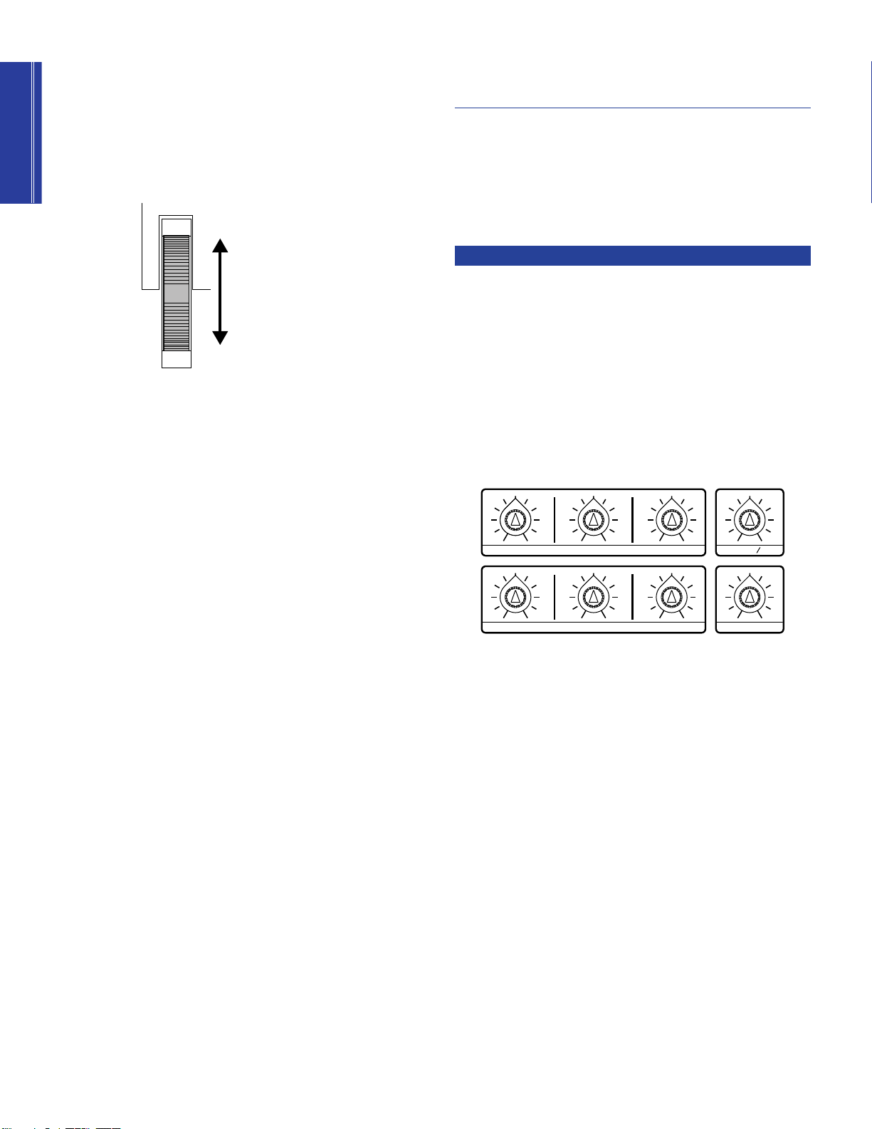
Getting Started
■ SCENE CONTROL Function
Maximum = Scene 2 only
Minimum = Scene 1 only
MODULATION
Halfway = Equal level of
Scene 1 and Scene 2
ATTACK
DECAY
RELEASE DATAASSIGN
1
ASSIGN 2
RESONANCE
CUTOFFCUTOFF LPFHPF
1. Press both [SCENE] buttons simultaneously.
The red LED to the left of both [SCENE] buttons will light to
indicate the SCENE CONTROL function is active.
2. Roll the MODULATION wheel forward and back to adjust
the relative levels of each Scene.
Performance Editing And
Store
As a
control synthesizer
which are readily available as you play, including SOUND
CONTROL knobs for direct tone modification, an Arpeggiator
with a wide selection of arpeggiated chord types and timing
resolutions, and many more. The next three steps on our tour are
actually Performance Edit functions and as such will cause the
edit mark (“E”) to appear in the LCD.
SOUND CONTROL Knobs
The SOUND CONTROL knobs give you direct access to eight
different parameters. All you have to do is turn them left and right
to either slightly or radically alter the tone. They’re so much fun,
you can literally get lost for hours at a time just tweaking the
filters and resonance settings alone — so go ahead and try them
all out!
the CS2x features easy editing functions
As shown in the illustration above, the position of the
MODULATION wheel determines the relative levels of each
Scene, with minimum controller position playing Scene 1 and
maximum position playing Scene 2. Any position between the
two extremes (between a range of 0 ~ 127) will play a blend of
both Scenes accordingly.
n
You can also use a connected Foot Controller for SCENE
CONTROL (pages 12 and 64).
■ Creating And Storing Scenes
You can easily create your own Scenes with the SOUND
CONTROL knobs and store them in a Performance — either
temporarily in the Scene buffer for the currently selected Preset
or User Performance, or permanently in a User Performance. For
details, see page 67.
The center stop position represents the original parameter settings
as stored in the selected Performance, so it only takes a glance at
the various knob positions to know where you stand. And don’t
forget, if you come up with a tone you like, you can store it in
one of the two Scene memories for instant recall (page 67).
A description of the default function assigned to each SOUND
CONTROL knob (printed on the panel below each knob) is
provided on page 19. You can also assign whatever parameters
you like to each knob using the panel edit matrix (page 64).
n
When a Scene is selected or the SCENE CONTROL function
is active, turning the SOUND CONTROL knobs will have no
affect on the tone.
26
Page 27
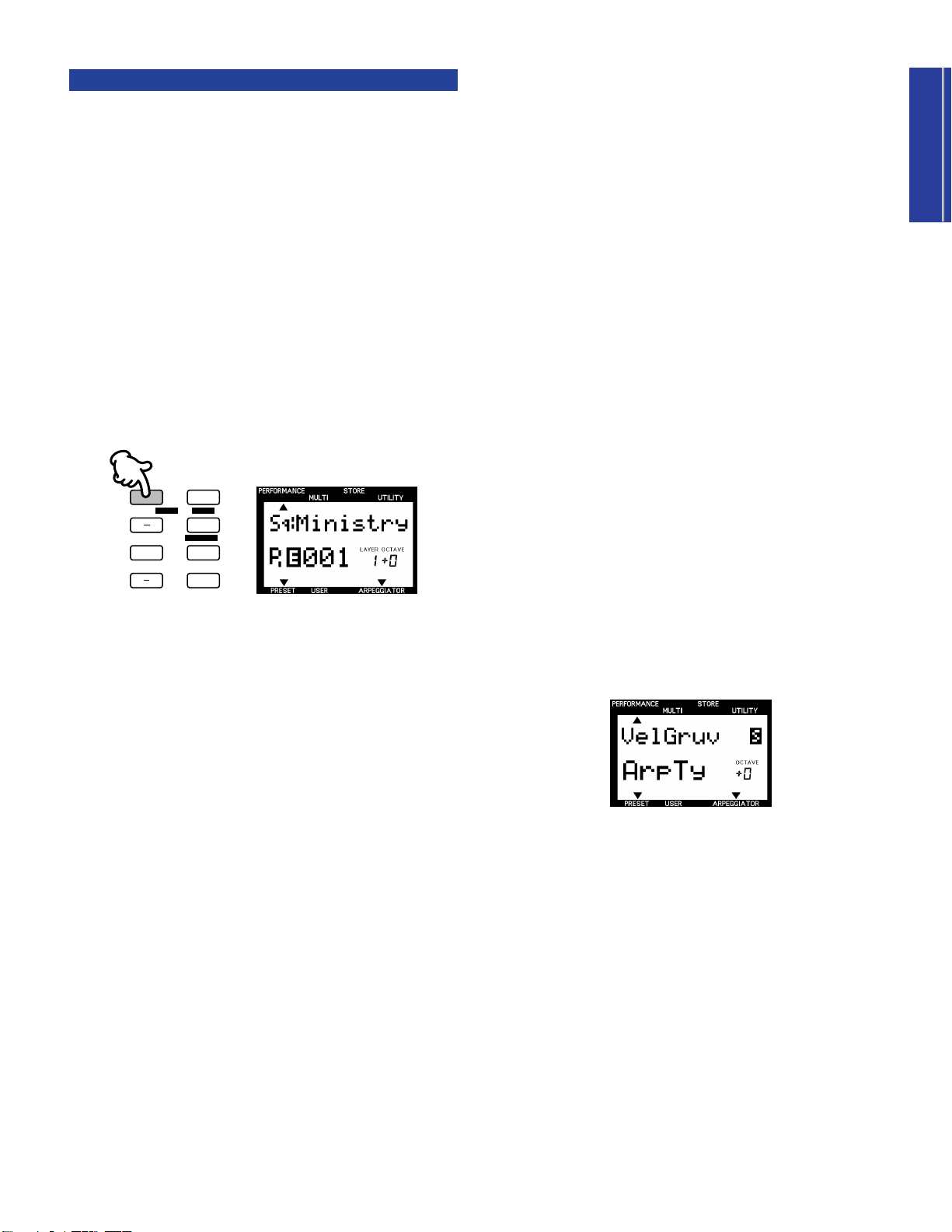
Getting Started
The Arpeggiator
ARPEGGIO
HOLD SHIFT
OCTAVE
PART/LAYER/
+
PRESET USER
PROGRAM
+
The Arpeggiator is another function that you can get carried away
with for hours on end! You’ve probably noticed by now that some
Performances use the Arpeggiator as part of their makeup to
generate arpeggiated chords automatically as you play. What’s
more, the Arpeggiator data can be output as MIDI messages via
the MIDI OUT terminal and recorded by a connected music
sequencer.
Just
how
they play depends on the TYPE, TEMPO, SUBDIVIDE
and SPLIT settings available in the Common Edit 1 menu (page
43) plus the number of notes you play on the keyboard.
(Performances with fast attacks tend to provide the best results.)
n
The Arpeggiator functions are not available in Multi Play
mode.
■ Arpeggiator Hold
The handy ARPEGGIATOR HOLD function lets you play a chord
to start the automatic arpeggio, then take your hands away from
the keyboard and have the arpeggios continue in a loop without
stopping. When you play another chord the arpeggio will change
accordingly.
1. Hold [SHIFT] and press [ARPEGGIO]. The “ARPEGGIATOR”
indicator in the LCD will start blinking.
2. Play a chord and take your hand away. Then play other
chords in the same way to get a feel for the right timing
required.
To stop the arpeggiated chords, press [ARPEGGIO]. To turn off
the ARPEGGIATOR HOLD function but leave the Arpeggiator on,
hold a chord and press [ARPEGGIO] twice.
■ Arpeggiator On/Off
1. Press [ARPEGGIO]. An indicator will appear in the lower
right area of the LCD above the word “ARPEGGIATOR”.
2. Play a series of chords and variate the number of notes (odd
and even) to hear how differently the arpeggiated chords
sound.
To turn off the Arpeggiator, press [ARPEGGIO] again.
■ Arpeggiator Split
The ARPEGGIATOR SPLIT function greatly increases the realtime performance capability of the CS2x. When ARPEGGIATOR
SPLIT is activated, any chord you play to the left of the split point
(B2 and below) will produce an arpeggiated chord, while chords
you play to the right of the split point will play normally.
1. Press [ARPEGGIO] to activate the Arpeggiator function.
2. Set the EDIT PARAMETER ROTARY switch to the Common
Edit 1 menu.
3. Hold [SHIFT] and press the left-most Parameter Value
[UP/DOWN] button (ARPEGGIATOR TYPE parameter).
4. Pressing [UP] will turn on the ARPEGGIATOR SPLIT
function.
A reversed type letter “S” will display in the LCD next to the TYPE
name to indicate the ARPEGGIATOR SPLIT function is on. To turn
it off, hold [SHIFT] and press [DOWN].
n
For more information, see page 44.
27
Page 28

Getting Started
■ Arpeggiator Parameter Settings
PERFORMANCE
MULTI
DEMO
STORE
UTILITY
P BEND
RANGE
TYPE
ARPEGGIATOR
TEMPO
PMOD
SUB
DIVIDE
PERFORM
LEVEL
MW
FMOD
CUTOFF
REV
TYPE
CHO
TYPE
VARI
TYPE
VARI
PARAM
PERFORM
NAME
VARI
DATA
ASSIGN1
PARAM
PORTA
SWITCH
TIME
EFFECT
VARI
EF
FC
CUTOFF
FMOD
COMMON
ASSIGN
BANK
PROGRAM
ATK
TIME
ATK
TIME
DCY
TIME
DCY
TIME
FEG
AEG
SUS
LEVEL
SUS
LEVEL
VOLUME
PAN
REL
TIME
REL
TIME
AMOD PMOD
INIT
LEVEL
ATK
TIME
REV
SEND
EFFECT
CHO
SEND
VARI
SEND
ATK
LEVEL
FMOD
LFO
PEG
DCY
TIME
WAVE
FILTER
CUTOFF
REZ
SPEED
REL
TIME
REL
LEVEL
PHASE
INIT
POLY
MONO
ASSIGN
2
DATAPARAMDEPTHOFFSET
VEL
LIMIT
HIGH
LIMIT
HIGH
LIMIT
LOW
LIMIT
LOW
NOTE
TUNE
NOTE
SFT
DETUNE
LAYER
The main Arpeggiator parameters include TYPE, TEMPO and
SUBDIVIDE. TYPE determines the arpeggio characteristics (up,
down, up and down, random, etc.). TEMPO of course controls
the speed of the arpeggiated chords. SUBDIVIDE determines the
arpeggio timing resolution (eighths, sixteenths, dotted notes,
etc.).
1. Activate the ARPEGGIATOR HOLD function and play a
chord.
2. Set the EDIT PARAMETER ROTARY switch to the Common
Edit 1 menu.
3. Press the TYPE [UP/DOWN] button and try out each
available setting. Also press SUBDIVIDE [UP/DOWN] to
hear how each of these settings affect each TYPE setting.
n
For more information, see Arpeggio Pattern Length,
following, and page 43. Also see the Arpeggiator Type List,
page 43.
Arpeggio Pattern Length
The length of a CS2x arpeggio pattern is determined by three
factors which work together simultaneously: TYPE and
SUBDIVIDE settings, and the total number of notes you play for
an arpeggiated chord.
For example, say you play an arpeggiated pattern with a fournote chord, such as a C major triad with an octave in the root. If
SUBDIVIDE is set to “1/8”, the Arpeggiator breaks down the
chord into eighths, and then arpeggiates it based on the TYPE
setting. If TYPE is set to “UpOct2” the arpeggio will climb over
two octaves, and will repeat after four beats. Then, if you change
SUBDIVIDE to “1/16”, the arpeggio will repeat after two beats.
Furthermore, if you then change TYPE to “UpOct1”, the arpeggio
will repeat after only one beat.
Because the number of notes you play in the chord has a direct
relationship on the pattern length based on SUBDIVIDE
resolution, sometimes unwanted syncopations may be
generated. As a general rule, you can avoid this by choosing an
even number of chord notes for even-numbered SUBDIVIDE
resolutions (1/4, 1/8, 1/16 and 1/32) and an odd number of notes
(e.g. three-note or five-note chords) with odd-numbered
resolutions (1/6, 1/12, 1/24).
However, this doesn’t apply for dotted note rhythms (3/8, 3/16
and 3/32). These resolutions are particularly interesting for oddnumbered beats (e.g. 3/8 or 6/8), so you will need to play chords
with an even number of notes to correctly play back these threepart rhythms.
As an example, set TYPE to “UpOct2” and SUBDIVIDE to “3/8”
resolution. Playing a triad will place the root note on the first beat
in the fourth bar, generating irregular cycles. A four-note chord,
however, generates symmetrical 4-bar cycles. The root note will
be repeated after the first cycle on bar 3, after the second cycle
on bar 5 and after the third cycle on bar 7, and so on, always
landing on the first beat.
In the case of the special Arpeggiator types (16-40), you will
notice that these aren’t particularly effective with triplet rhythms.
Best results are achieved with a 4/4 beat and a SUBDIVIDE
resolution of “1/16”, “1/8” or “1/32”.
28
Page 29
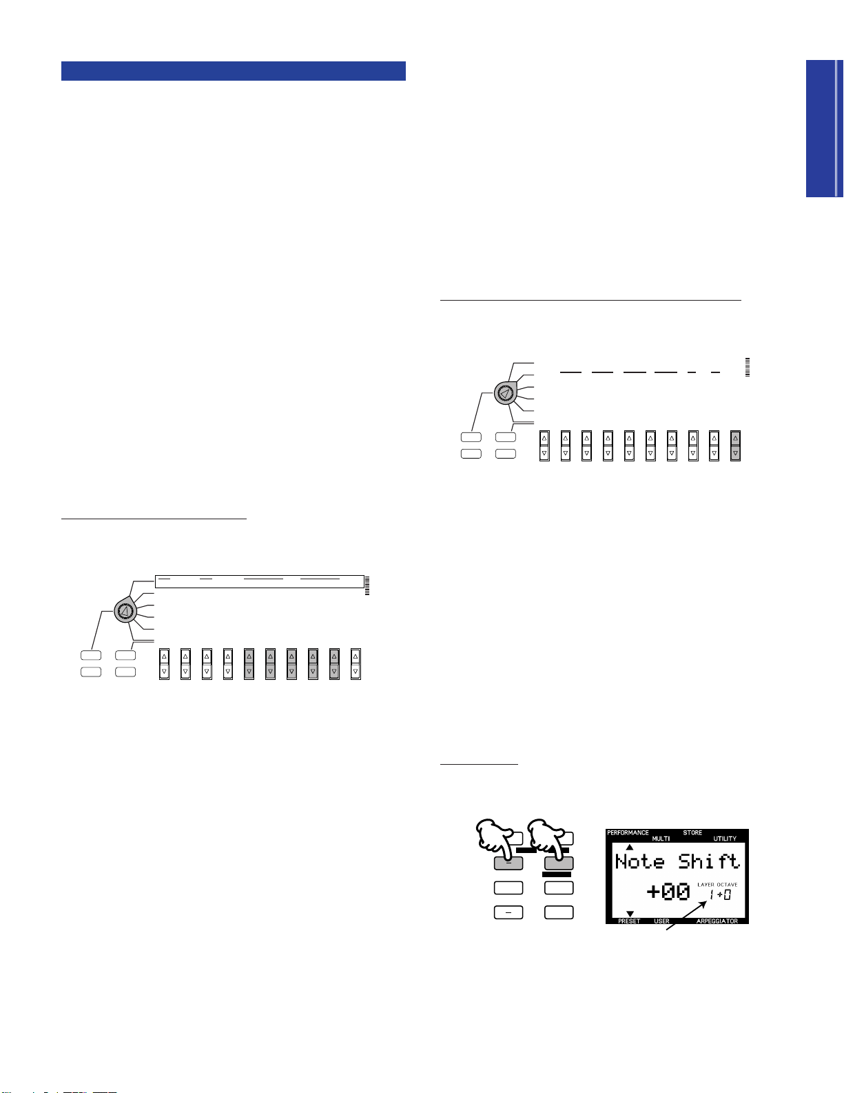
Getting Started
Panel Edit Matrix
PERFORMANCE
MULTI
DEMO
STORE
UTILITY
P BEND
RANGE
TYPE
ARPEGGIATOR
TEMPO
PMOD
SUB
DIVIDE
PERFORM
LEVEL
MW
FMOD
CUTOFF
REV
TYPE
CHO
TYPE
VARI
TYPE
VARI
PARAM
PERFORM
NAME
VARI
DATA
ASSIGN1
PARAM
PORTA
SWITCH
TIME
EFFECT
VARI
EF
FC
CUTOFF
FMOD
COMMON
BANK
PROGRAM
ATK
TIME
ATK
TIME
DCY
TIME
DCY
TIME
FEG
AEG
SUS
LEVEL
SUS
LEVEL
VOLUME
PAN
REL
TIME
REL
TIME
AMOD PMOD
INIT
LEVEL
ATK
TIME
REV
SEND
EFFECT
CHO
SEND
VARI
SEND
ATK
LEVEL
FMOD
LFO
PEG
DCY
TIME
WAVE
FILTER
CUTOFF
REZ
SPEED
REL
TIME
REL
LEVEL
PHASE
INIT
POLY
MONO
ASSIGN
2
DATAPARAMDEPTHOFFSET
VEL
LIMIT
HIGH
LIMIT
HIGH
LIMIT
LOW
LIMIT
LOW
NOTE
TUNE
NOTE
SFT
DETUNE
LAYER
ARPEGGIO
HOLD SHIFT
OCTAVE
PART/LAYER/
+
PRESET USER
PROGRAM
+
Indicates currently selected Layer
PERFORMANCE
MULTI
DEMO
STORE
UTILITY
SYSTEM
P BEND
RANGE
TYPE
ARPEGGIATOR
TEMPO
PMOD
SUB
DIVIDE
PERFORM
LEVEL
MW
FMOD
CUTOFF
REV
TYPE
CHO
TYPE
VARI
TYPE
VARI
PARAM
PERFORM
NAME
VARI
DATA
ASSIGN1
PARAM
PORTA
SWITCH
TIME
EFFECT
VARI
EF
FC
CUTOFF
FMOD
COMMON
ASSIGN
MIDI
BANK
PROGRAM
ATK
TIME
ATK
TIME
DCY
TIME
DCY
TIME
FEG
AEG
SUS
LEVEL
SUS
LEVEL
VOLUME
PAN
REL
TIME
REL
TIME
AMOD PMOD
INIT
LEVEL
ATK
TIME
REV
SEND
EFFECT
CHO
SEND
VARI
SEND
ATK
LEVEL
FMOD
LFO
PEG
DCY
TIME
WAVE
FILTER
CUTOFF
REZ
SPEED
REL
TIME
REL
LEVEL
PHASE
INIT
POLY
MONO
ASSIGN
2
DATAPARAMDEPTHOFFSET
VEL
LIMIT
HIGH
LIMIT
HIGH
LIMIT
LOW
LIMIT
LOW
NOTE
TUNE
NOTE
SFT
DETUNE
LAYER
Although the features we’ve explained so far no doubt provide
you with a wealth of tone control and great music making
options, we’ve really only just begun to scratch the surface of the
CS2x’s power!
The panel edit matrix gives you six menus of Performance Edit
parameters with virtually limitless options for tone control and
customized User Performance creation using the EDIT
PARAMETER ROTARY switch in conjunction with the ten
parameter [UP/DOWN] buttons.
Each parameter is explained and available settings are listed in
the Reference section (starting on page 39). Reading through it —
along with just rolling up your sleeves and trying each one out
one-by-one — will end up making you a veritable CS2x expert!
For the sake of giving you a well-rounded tour right now without
getting in too deep, however, why not try experimenting with a
few basic COMMON and LAYER edit menus to help you get
comfortable dealing with collective and individual Performance
Layers.
■ COMMON Parameters
Each CS2x Performance is made up of anywhere between one
and four Layer voices. Changes you make to parameter settings
in the two COMMON menus will affect all Layer voices equally.
Try out the many different effects.
1. Set the EDIT PARAMETER ROTARY switch to the Common
Edit 1 menu.
3. Use the VARI TYPE [UP/DOWN] button to try out the
different Variation effect types. Use the VARI PARAM
[UP/DOWN] button to select available Variation effect
parameters. Use the VARI DATA [UP/DOWN] button to
select specific parameter data value settings.
You can set the amount of Reverb and Chorus for each Layer
using the EFFECT REV SEND and CHO SEND parameters,
respectively, located in the Layer Edit 4 menu. When EFFECT
VARI SEND is set to “on”, however, Reverb and Chorus send
levels are applied equally to all Layers.
n
For more information about effects, see page 70. Also see the
separate “Data List” book.
Customize the parameter of the ASSIGN 1/DATA knob.
1. Set the EDIT PARAMETER ROTARY switch to the Common
Edit 2 menu.
2. Use the ASSIGN1 PARAM [UP/DOWN] button to determine
which parameter will be affected by the ASSIGN 1/DATA
knob.
There are 30 choices in all. You could, for example, use it to
control Arpeggiator tempo, or left and right panning of the sound,
the overall pitch and much more.
2. Use the REV TYPE [UP/DOWN] button to try out the
different Reverb effect types. Use the CHO TYPE
[UP/DOWN] button to try out the different Chorus effect
types.
n
For a list of available parameters, see page 65.
■ LAYER Parameters
There are four menus of LAYER parameters which affect only the
currently selected Layer when you edit them. (Note that although
the PORTA SWITCH parameter is located in the Common Edit 2
menu, it is in fact a Layer parameter and therefore can be set for
each individual Layer voice.)
Select a Layer.
Press the PART/LAYER [-] and [+] buttons to select a desired
Layer.
29
Page 30

Getting Started
Change the Layer voice.
PERFORMANCE
MULTI
DEMO
STORE
UTILITY
P BEND
RANGE
TYPE
ARPEGGIATOR
TEMPO
PMOD
SUB
DIVIDE
PERFORM
LEVEL
MW
FMOD
CUTOFF
REV
TYPE
CHO
TYPE
VARI
TYPE
VARI
PARAM
PERFORM
NAME
VARI
DATA
ASSIGN1
PARAM
PORTA
SWITCH
TIME
EFFECT
VARI
EF
FC
CUTOFF
FMOD
COMMON
BANK
PROGRAM
ATK
TIME
ATK
TIME
DCY
TIME
DCY
TIME
FEG
AEG
SUS
LEVEL
SUS
LEVEL
VOLUME
PAN
REL
TIME
REL
TIME
AMOD PMOD
INIT
LEVEL
ATK
TIME
REV
SEND
EFFECT
CHO
SEND
VARI
SEND
ATK
LEVEL
FMOD
LFO
PEG
DCY
TIME
WAVE
FILTER
CUTOFF
REZ
SPEED
REL
TIME
REL
LEVEL
PHASE
INIT
POLY
MONO
ASSIGN
2
DATAPARAMDEPTHOFFSET
VEL
LIMIT
HIGH
LIMIT
HIGH
LIMIT
LOW
LIMIT
LOW
NOTE
TUNE
NOTE
SFT
DETUNE
LAYER
PERFORMANCE
MULTI
DEMO
STORE
UTILITY
MASTER
TUNE
KBD
TRANS
SYSTEM
P BEND
RANGE
TYPE
ARPEGGIATOR
TEMPO
PMOD
BANK
PROGRAM
ATK
TIME
ATK
TIME
DCY
TIME
DCY
TIME
FEG
AEG
TUNE
NOTE
SFT
DETUNE
PERFORMANCE
MULTI
DEMO
STORE
UTILITY
P BEND
RANGE
TYPE
ARPEGGIATOR
TEMPO
PMOD
SUB
DIVIDE
PERFORM
LEVEL
MW
FMOD
CUTOFF
REV
TYPE
CHO
TYPE
VARI
TYPE
VARI
PARAM
PERFORM
NAME
VARI
DATA
ASSIGN1
PARAM
PORTA
SWITCH
TIME
EFFECT
VARI
EF
FC
CUTOFF
FMOD
COMMON
BANK
PROGRAM
ATK
TIME
ATK
TIME
DCY
TIME
DCY
TIME
FEG
AEG
SUS
LEVEL
SUS
LEVEL
VOLUME
PAN
REL
TIME
REL
TIME
AMOD PMOD
INIT
LEVEL
ATK
TIME
REV
SEND
EFFECT
CHO
SEND
VARI
SEND
ATK
LEVEL
FMOD
LFO
PEG
DCY
TIME
WAVE
FILTER
CUTOFF
REZ
SPEED
REL
TIME
REL
LEVEL
PHASE
INIT
POLY
MONO
ASSIGN
2
DATAPARAMDEPTHOFFSET
VEL
LIMIT
HIGH
LIMIT
HIGH
LIMIT
LOW
LIMIT
LOW
NOTE
TUNE
NOTE
SFT
DETUNE
LAYER
This is a quick and effective way to easily create an entirely new
Performance!
1. Select a desired Layer.
2. Set the EDIT PARAMETER ROTARY switch to the Layer Edit
4 menu and press the BANK [UP/DOWN] button to select
an available bank.
3. Press the PROGRAM [UP/DOWN] button to select an
available voice.
To set the level of each Layer, simply repeat the process. When
the VOLUME screen is displayed, simply selecting a Layer will
reveal its level setting.
User Performance Store
Now that we’re at the end of the Performance mode tour, it’s
highly likely that you created something along the way that’s
worth storing as a User Performance for recall later. In order to
execute a Performance Store operation, the Performance Name
screen must be displayed in the LCD.
To assign a new voice to each Layer, simply repeat the process.
When the BANK or PROGRAM screen is displayed, simply
selecting a Layer will reveal which bank or voice is currently
selected.
n
For a list of available voices for Performance Layers, see the
separate “Data List” book.
Adjust the relative volume levels of each Layer.
This is a quick and easy way to reshape a Performance which
uses two or more Layers.
1. Select a desired Layer.
2. Set the EDIT PARAMETER ROTARY switch to the Layer Edit
4 menu and press the VOLUME [UP/DOWN] button to
adjust the level.
1. Press the [STORE] button. The Performance Store screen will
display.
2. Press [USER] to select a User Performance bank (U1 or U2).
3. Use the NUMERIC KEYPAD to select the program number
(1 ~ 128) in which you want to store the User Performance.
The number will flash in the screen.
4. Press [ENTER].
A “Sure?” prompt will appear in the LCD. Press [YES] to store the
Performance. Press [NO] to abort the operation.
30
Page 31
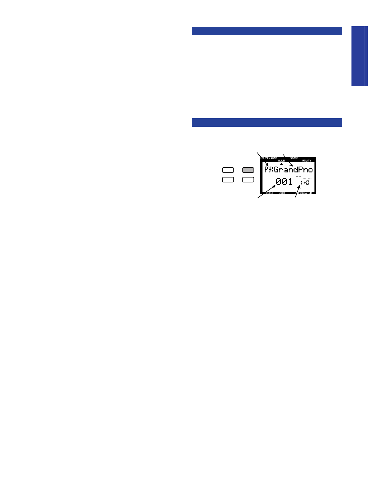
Getting Started
Multi Play Mode
PERFORMANCE MULTI
DEMO
STORE UTILITY
Part Number
Voice Name
Category
Program (Voice) Number
Multi Play mode is especially suitable for multitimbral song
production with up to 16 individual musical instrument “Parts”
using an external MIDI sequencer or computer running a MIDI
music sequencer program. Each CS2x Part is made up of one of
the 586 normal voices and 20 drum voices as well as volume,
panning, effect send and other settings. The CS2x’s 64 notes
maximum available polyphony make sure even your most
intricate composition will record and play back faithfully.
The CS2x is an excellent master MIDI keyboard controller for
sequence recording since it not only transmits MIDI note
messages as you play the keyboard, it also sends program change
messages to change voices as you press panel buttons, and
continuous control change message as you use the PITCH and
MODULATION wheels, SOUND CONTROL knobs and Foot
Controllers.
The CS2x is also an extremely flexible multitimbral MIDI “tone
module” since it can receive MIDI system exclusive and other
messages which give you far greater control over the individual
effects and other parameters not possible using the panel
functions. As an XG format tone generator the CS2x can play
commercially available XG music data (marked with the XG
logo) using an external sequencer as well as General MIDI
System Level 1 files (marked with the GM logo). When used with
a music sequencer software application such as Yamaha’s
XGworks, you can enjoy the full benefits of the CS2x’s XG
capabilities, all with an easy-to-use graphic-oriented user
interface.
If you program the data for all of your basic voice, effects and
other Part settings at the head of the song before the music starts,
you can be assured that the CS2x will always play just as you
want it to, without having to make any tedious panel settings
when setting up.
Sequencer Setup
If you’re using a stand-alone hardware-based sequencer, connect
it to the CS2x’s MIDI terminals using MIDI cables. If a computer,
connect it to the TO HOST terminal using the appropriate cable.
(For details about connections, see page 12.)
n
Refer to the owner’s manual for your sequencer regarding
information about setting it up for multitimbral recording and
play.
The following steps are related to setting up the CS2x for
multitimbral recording and play.
Multi Play Mode Select
Simply pressing the [MULTI] button will enter Multi Play mode.
Take a look at the LCD and see which Part is selected (1 ~ 16).
Note that if you play the keyboard the voice you’ll be playing will
be that of the selected Part. You can use the NUMERIC KEYPAD
(0 ~ 9) and [ENTER] as well as the PROGRAM [-]/[+] buttons to
select any of the basic 128 GM normal voices.
A new CS2x or one that has had the factory settings recalled
(page 69) will be set at PART 1 = “#001-Grand Piano”.
In all, you can store up to nine CS2x Multi setups. Each might act
as a template for an easy start to your most frequently used music
composing, studio recording or live performance situations (page
67).
For the sake of the Quick Tour, we’ll explain the basic Multi Play
mode setup operations, then give you a brief presentation of
putting it all to practical use with a computer based music
sequencer, Yamaha’s XGworks.
n
For more information, see pages 32 and 57. Also see the
separate “Data List” book.
31
Page 32

Getting Started
Part Assign
PERFORMANCE
MULTI
DEMO
STORE
UTILITY
P BEND
RANGE
TYPE
ARPEGGIATOR
TEMPO
PMOD
SUB
DIVIDE
PERFORM
LEVEL
MW
FMOD
CUTOFF
REV
TYPE
CHO
TYPE
VARI
TYPE
VARI
PARAM
PERFORM
NAME
VARI
DATA
ASSIGN1
PARAM
PORTA
SWITCH
TIME
EFFECT
VARI
EF
FC
CUTOFF
FMOD
COMMON
BANK
PROGRAM
ATK
TIME
ATK
TIME
DCY
TIME
DCY
TIME
FEG
AEG
SUS
LEVEL
SUS
LEVEL
VOLUME
PAN
REL
TIME
REL
TIME
AMOD PMOD
INIT
LEVEL
ATK
TIME
REV
SEND
EFFECT
CHO
SEND
VARI
SEND
ATK
LEVEL
FMOD
LFO
PEG
DCY
TIME
WAVE
FILTER
CUTOFF
REZ
SPEED
REL
TIME
REL
LEVEL
PHASE
INIT
POLY
MONO
ASSIGN
2
DATAPARAMDEPTHOFFSET
VEL
LIMIT
HIGH
LIMIT
HIGH
LIMIT
LOW
LIMIT
LOW
NOTE
TUNE
NOTE
SFT
DETUNE
LAYER
ARPEGGIO
HOLD SHIFT
OCTAVE
PART/LAYER/
+
PRESET USER
PROGRAM
+
Number of currently selected Part
PERFORMANCE
MULTI
DEMO
STORE
UTILITY
P BEND
RANGE
TYPE
ARPEGGIATOR
TEMPO
PMOD
SUB
DIVIDE
PERFORM
LEVEL
MW
FMOD
CUTOFF
REV
TYPE
CHO
TYPE
VARI
TYPE
VARI
PARAM
PERFORM
NAME
VARI
DATA
ASSIGN1
PARAM
PORTA
SWITCH
TIME
EFFECT
VARI
EF
FC
CUTOFF
FMOD
COMMON
BANK
PROGRAM
ATK
TIME
ATK
TIME
DCY
TIME
DCY
TIME
FEG
AEG
SUS
LEVEL
SUS
LEVEL
VOLUME
PAN
REL
TIME
REL
TIME
AMOD PMOD
INIT
LEVEL
ATK
TIME
REV
SEND
EFFECT
CHO
SEND
VARI
SEND
ATK
LEVEL
FMOD
LFO
PEG
DCY
TIME
WAVE
FILTER
CUTOFF
REZ
SPEED
REL
TIME
REL
LEVEL
PHASE
INIT
POLY
MONO
ASSIGN
2
DATAPARAMDEPTHOFFSET
VEL
LIMIT
HIGH
LIMIT
HIGH
LIMIT
LOW
LIMIT
LOW
NOTE
TUNE
NOTE
SFT
DETUNE
LAYER
Part Parameter Edit
You can assign any of the 586 XG normal voices (including the
128 GM voices) or 20 drum voices to each of the 16 Parts.
1. Use the PART/LAYER [-] and [+] buttons to select a desired
Part, as displayed in the LCD.
2. Use the BANK [UP/DOWN] button to select a desired voice
bank.
3. Use the PROGRAM [UP/DOWN] button to select a desired
voice.
In Multi Play mode there is only one menu of edit parameters
available, as printed directly above each [UP/DOWN] button.
The position of the EDIT PARAMETER ROTARY switch is
irrelevant.
1. Select a desired Part.
2. Use the [UP/DOWN] button directly below the name of the
parameter which you want to edit to change the available
settings.
Repeat the procedure to edit each individual Part.
n
For details about each Multi edit parameter and available
settings, see page 58.
n
For details about storing a User Multi, see page 68.
n
For a list of available banks and voices, see the separate
“Data List” book.
32
Page 33

XG Operation
Getting Started
XG represents the current state-of-the-art in multitimbral MIDI
technology. In the early days of MIDI, it was very difficult to take
music data created using one particular sequencer and play it
back on another because the instruments assigned to the different
parts were different for each maker and even individual
composer. This meant that when different musicians came
together with their varied MIDI instruments and music data, it
required literally hours and hours of painstaking MIDI channel
and other reassignment and checking operations before the
music session could even begin! Thankfully those nightmare days
are long gone.
General MIDI System Level 1 (GM) was
created in order to standardize the voice
assignments for 128 normal voices plus
drums, so that songs created in the GM
format would play back exactly as the
composer intended regardless of the tone generator
manufacturer — as long as the device supported the GM
standard as marked with the GM logo. These days virtually all
electronic musical instruments and software-based music and
game products support the GM standard.
GM is not without its limitations, however, which is why Yamaha
created the XG format which maintains full compatibility with
the basic MIDI and GM standards, while at the same time
significantly increasing the range of expressiveness possible
through much greater control over voice modifications and
effects, plus provides for many more normal and drum voices to
be available for use.
Multi Play In
Performance Mode
While Multi Play mode is ideal for recording and playback of 16part compositions using the XG voices, you can also use
Performance mode for multitimbral play (using an external music
sequencer) in order to enjoy the full benefits of the broader
dimension of sound possible by the Preset or User Performances,
plus Scene switching, arpeggiated chords and all of the SOUND
CONTROL knobs.
To demonstrate how you can get the biggest benefits from the
CS2x’s multitimbral capabilities, we show you how to put its
MIDI parameter control features into practical use by describing
a few basic operations when using the CS2x with a computer and
Yamaha’s XGworks music sequencer application, a truly
professional level MIDI music sequencer which features
everything you’d expect from the world’s most popular music
software applications, plus the added benefit of greater ease of
access to and control over XG commands. It even accommodates
and lets you create songs in all popular formats, including as
digital audio data such as WAV files.
When the CS2x is used for Multi Play in Performance mode, the
Performance part is programmed as Part 1, and the 12 available
voice parts are programmed in Parts 5 ~ 16. Which voice is used
for each of the 12 Parts is determined by MIDI bank select,
program change and other messages recorded as data in the
sequencer tracks. (For more information, see pages 35 and 56.)
Many of the new XG voices are
variations of basic GM voices which are
stored in additional banks. Each bank is
associated with a specific type of
variation, so that voices are easy to
locate. When using an external sequencer to control the CS2x,
additional banks are selected by the appropriate Bank Select LSB
(Least Significant Bit) and MSB (Most Significant Bit) values.
The XG format also supports a full SFX bank of extension effects,
which are selected by a Bank Select MSB value of 40H and LSB
0H.
What’s more, the XG format also offers high level effects support,
enabling control of effects types, circuit operation, plus internal
parameter settings for both basic and elaborate effects. This
means you can freely control the parameters of the CS2x’s 12
Reverb, 14 Chorus and 62 Variation types of effects
independently using an external sequencer.
The CS2x also features another play mode — TG300B mode —
which lets you play back commercially available MIDI files in
this format.
For more information about MIDI and MIDI related parameters,
see page 72. Also see the separate “Data List” book.
33
Page 34

Getting Started
Using The CS2x With
Parameter
Section
Each MIDI Transmit Channel
XGworks
The XGworks Music Sequencer software application is a
powerful all-in-one “DTM” Desktop Music composing, editing
and mixing system for Windows95. XGworks is especially suited
for the CS2x.
When you start up XGworks, you’ll be greeted by an Application
Window from which you can access a variety of tools for
recording and precise editing of your music.
In XGworks the Track View Window is the central point for song
creation. There are many other tools you can used to construct
your composition.
• The Piano Roll Window and the Drum Window let you edit
MIDI notes graphically.
• The Staff Window displays the notes like sheet music.
• The List Window and the Master Track Window show the data
for each MIDI event.
• The Mixer Window gives you the capability to control many
different functions in realtime while playing back your song.
• The XG Editor Window lets you edit the parameters for the
CS2x.
1. Set the CS2x MIDI Performance receive
channels.
Using Utility mode, set the CS2x MIDI Receive Channel for the
Performance (Part 1 = “A”), as well as Parts 5 ~ 16 (page 63), as
the situation merits.
n
To select the Layer (“A”) or Part (“5 ~ 16”) which you want to
assign a MIDI channel to, use the PART/LAYER [-]/[+]
buttons.
n
If the Performance and another Part are set to the same MIDI
receive channel number, then both timbres will play
simultaneously. Keep this in mind as you set up your Parts, so
that none will unintentionally play the wrong Part data.
n
When using the CS2x as the MIDI master keyboard device
for MIDI data input, you determine which channel the CS2x
is transmitting on using the Utility mode TRANS CH
parameter (page 63).
Every window has many functions which make operation
intuitive and precise, while boosting your productivity and even
having more fun!
n
XGworks operations may appear different depending on the
version of XGworks and your computer conditions.
2. Set the MIDI transmit channel for each
Part track in XGworks.
The Track View Window lets you confirm the MIDI channels for
each CS2x Part using the “Ch.” column.
Tr ack V iew Window
34
Page 35

Getting Started
3. Decide the voice for each Part.
Track 5
Track 6
Track 7
•
•
Track 10
•
•
Piano
Bass
Strings
•
•
Drums
•
•
Piano voice
Bass voice
Strings voice
•
•
Drums voice
•
•
Ch5
Ch6
Ch7
•
•
Ch10
•
•
Ch5
Ch6
Ch7
•
•
Ch10
•
•
XGworks XG/GM Tone Generator
Pan Control
Volume Fader
XGworks lets you use MIDI program change messages (page 75)
to call up the CS2x’s voices. There are many ways to do so. Take
a look at the Track View Window.
Based on the MIDI standard, each voice has its own bank
number and program number. Setting the appropriate bank select
and program change values will call up a specific CS2x voice.
You can set these in XGworks, with intuitive ease. You can assign
a voice to each Part (5 ~ 16).
4.
Set the volume and panning for each Part.
You can control the CS2x’s volume and panning for each Part
using control change messages (page 72) to change the values of
each, over a range of 0 ~ 127. From XGworks you can also
change these manually using the Mixer Window. This sends the
changes you make to volume fader and pan settings for each
individual MIDI channel as control change messages to each
corresponding CS2x Part.
In the parameter section of the Track View Window you can open
the Voice List. Like the CS2x, the voices are arranged in
categories. As shown, you can easily locate and select a voice by
choosing the basic category in column 1, which lists the types of
voice categories available column 2. Choosing a type will list the
available individual voices in column 3, available for selection.
Creating The Setup Data
You can set up the basic part parameters on the CS2x. You can
use the List Window to set up each track’s bank select and
program change data (for voices) at the top of the song as well as
control change data (for volume, panning, effects, etc.)
throughout the song so that the sequence software will play
everything back just as you want.
When you select a voice from the Voice List, that track’s MIDI
transmit channel transmits the bank number/program number
(bank select/program change) to the same MIDI receive channel
as set by the CS2x.
n
In order to ensure automatic setup of all voice and other
parameter settings, you can insert the proper bank
select/program change and other messages at the top of the
song, before the music data starts playing. With XGworks this
is all done with ease using the List Window.
n
For more information, see the owner’s manual for XGworks.
You can program Performance data at the beginning of or
throughout a song so that an original Performance is
automatically selected for playback. This means that even if the
particular User Performance is not stored in the CS2x, the
appropriate data will be transmitted before the song data begins
For details, see page 72.
so that your song plays exactly as you recorded it.
n
The voice changes when the CS2x receives the
corresponding bank select/program change messages. When
you use this method, you can select not only each Part’s
voice but a Performance. The XGworks List Window makes
this especially convenient. Since there are extra “material”
voices available for use in Performance mode, you can
assign any of these to Parts 5 ~ 16. For more information, see
the separate “Data List” book.
It requires setting up the sequencer for a Bulk Dump request to
receive the desired User Performance data. Following is an
explanation of how to do so using the real-time recording
function of XGworks as an example, where track 1 is used for
programming the User Performance data.
35
Page 36

Getting Started
Transmitting Performance Data
VWX
MNO
PQR STU
JKL
SPACE
YES
ENTER
&
GHI
NO
QUICK PC
DEF
ABC
YZ
,
.,
2
0
–
5
8
9
6
3
1
4
7
Press the Play button
to activate recording
Bulk transmit start
Confirm the channel
Select the track for
recording
Press the Record button to
activate recording Standby
1. In Performance mode, select the CS2x Performance you
want to transmit.
2. In Utility mode (TRANS CH parameter), set the MIDI
channel over which you want the CS2x to transmit the data,
such as channel 1.
3. In Utility mode (BULK DUMP parameter), select the “1P erf”
setting.
4. In XGworks, confirm that track 1 is set to channel 1 and
prepare for real-time recording.
6. When Performance data transmission is finished, stop the
XGworks recording. Use the List Window to confirm the
data received by XGworks. You can see that the MIDI data
format (BULK DUMP “3-6-4-2”, as shown in the separate
“Data List” book) hexadecimal messages have been
programmed.
List Window
In the Track View Window you can use the Scissors and Eraser
tools to delete data for measures that don’t need data.
For information about saving, see the owner’s manual for
XGworks.
When you play a song with XGworks that has the received data,
the appropriate CS2x Performance is selected automatically and
played precisely as you recorded it.
5. After starting recording with XGworks, press the CS2x’s
[ENTER] button to transmit the Performance data.
n
Depending on system exclusive data programmed at the top
of the song, you can have the sequencer automatically select
Performance mode, using the system exclusive message as
shown below. This way you can prevent an error caused by
transmitting the Performance bulk data when the CS2x is in
Multi Play mode.
F0 43 1n 63 50 00 06 03 F7 (hexadecimal)
n = Device Number
These settings aren’t limited for use with XGworks only, but will
work with other sequencers as well. Refer to the owner’s manual
of the particular sequencer for related information.
36
Page 37

Getting Started
Simply Dynamite: Yamaha MIDI Magic
Yamaha has a full line-up of professional MIDI instruments from
which you could choose in order to build up a MIDI music
system that’s perfect for your own individual needs. Two in
particular are especially suited for use with the CS2x, as follows:
• QY700 Music Sequencer Ideal for professionals and novices
alike, the QY700 is a full MIDI production center in its own
right complete with easy-to-use MIDI instrument and drum
part composing through a built-in database of musical style
phrases and “groove templates”, 32 “linear” tracks and 16
“pattern” tracks, a full XG multitimbral tone generator
including three digital multi-effects units, plus wide-ranging
editing and on-board mixing features.
• RM1x Sequence Remixer Ideal for dance DJs, the RM1x
features the same basic sequencing and editing functions of
the QY700 — along with hundreds of voices, 960 Preset
patterns and 800 User patterns — plus real-time performance
controls including a 16-key “microkeyboard” for easy
switching of patterns and 8 CONTROL knobs for dynamic
control of the sound on each track. There’s also an arpeggiator,
SMF compatibility, and much more.
37
Page 38

38
Page 39
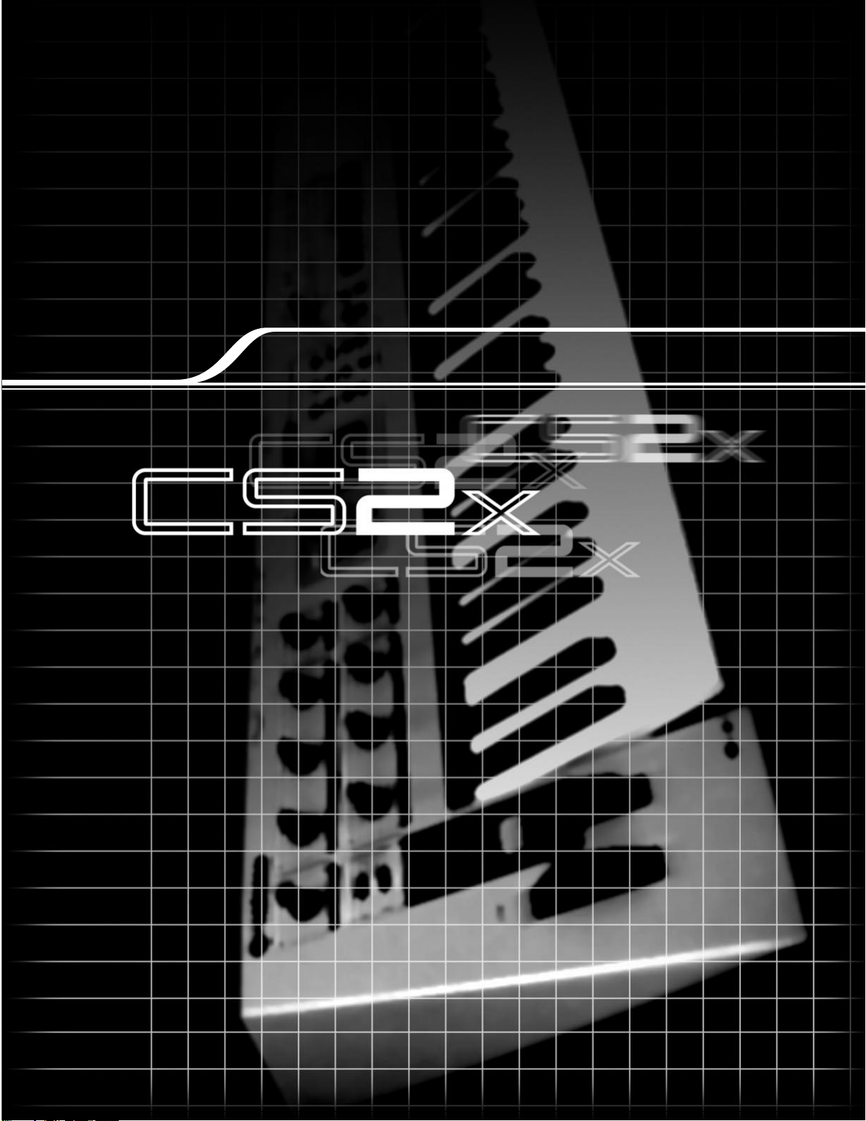
Feature Reference
Feature Reference
Page 40

II: 128 PerformanceI: 128 Performance
Preset Bank
(256 Performance)
II: 128 PerformanceI: 128 Performance
User Bank
(256 Performance)
PERFORMANCE MULTI
DEMO
STORE UTILITY
1
VWX
7
YZ'
8
&
*
9
MNO
4
PQR
5
STU
6
DEF
1
GHI
2
JKL
NO/
QUICK PC
YES
3
ABC
0
SPACE
ENTER
ARPEGGIO
HOLD SHIFT
OCTAVE
PART/LAYER/
+
PRESET USER
PROGRAM
+
ARPEGGIO
HOLD SHIFT
OCTAVE
PART/LAYER/
+
PRESET USER
PROGRAM
+
Feature Reference
Following is a description of each function in the various modes along with available parameter settings.
Performance Mode
Feature Reference
Performance Mode
In Performance mode you can choose from 256 Preset and 256 User Performances. A Performance consists of up to
four “Layer” voices playing simultaneously. You can easily edit each Layer within a Performance so that each sounds
and behaves uniquely. The many available edit parameters give you the flexibility to create a vast variety of
Performance timbres.
Entering Performance Mode
Press [PERFORMANCE]. A [▲] mark will appear in the LCD
below the word “PERFORMANCE” to indicate that Performance
mode is active.
To select the bank you want, press [PRESET] or [USER]. A [▼]
mark will appear in the LCD above the word “PRESET” or
“USER” to indicate which is selected.
PRESET
USER
Performance Play Mode
● Selecting A Bank
There are four banks available: two Preset banks (P1/P2) and
two User banks (U1/U2). Each bank contains 128
Performances.
Each time you press [PRESET] or [USER] toggles between P1/P2
and U1/U2 banks, respectively. The currently selected bank will
be indicated in the LCD to the left of the Performance number.
● Selecting A Performance
1. Use the NUMERIC KEYPAD (0 ~ 9) to select the
Performance number you want.
n
For more information about the factory Performances, see the
Performance Lists in the separate “Data List” book.
40
Page 41
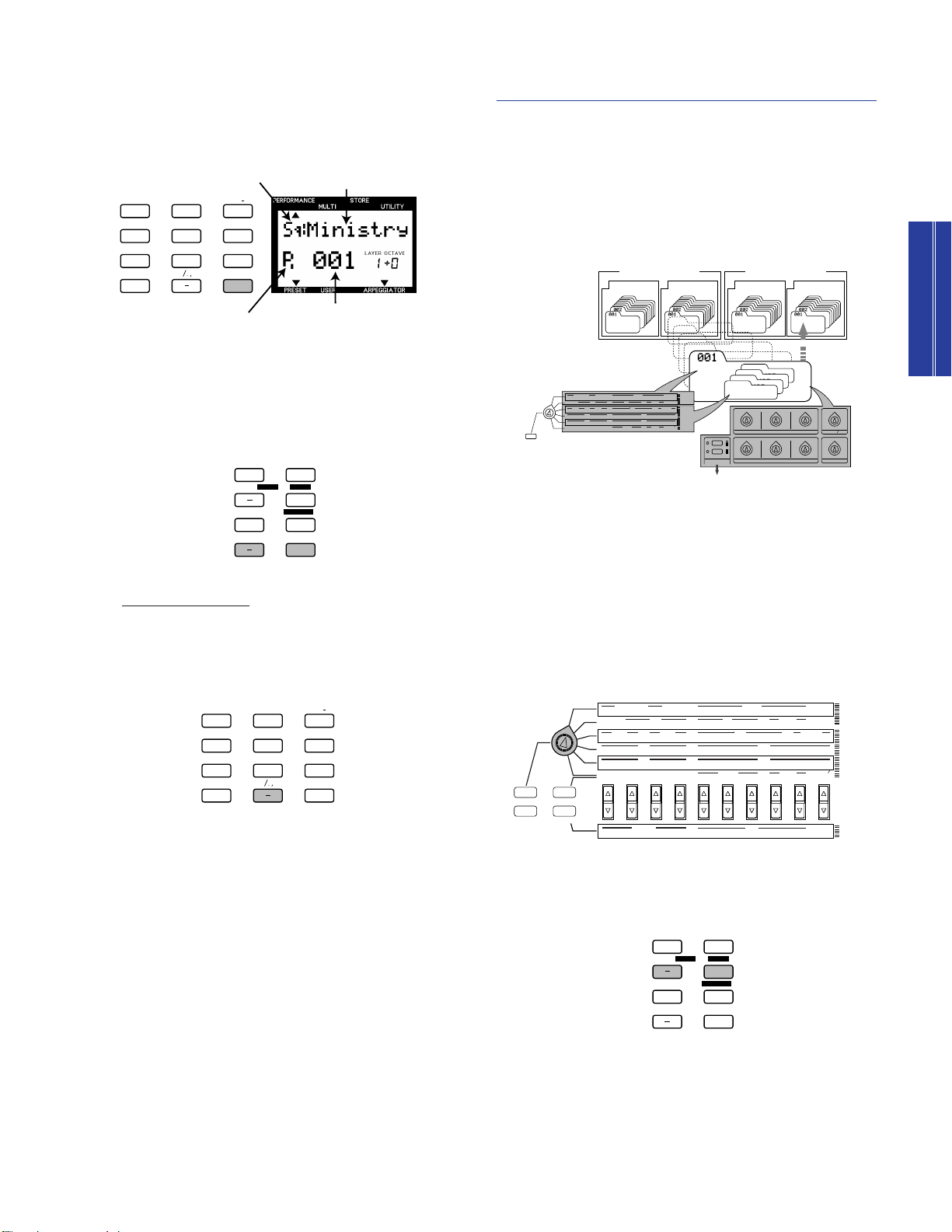
ARPEGGIO
HOLD SHIFT
OCTAVE
PART/LAYER/
+
PRESET USER
PROGRAM
+
PERFORMANCE
MULTI
DEMO
STORE
UTILITY
UTILITY
MASTER
TUNE
KBD
TRANS
VEL
CURVE
VEL
FIX
SYSTEM
P BEND
RANGE
TYPE
ARPEGGIATOR
TEMPO
PMOD
SUB
DIVIDE
PERFORM
LEVEL
MW
FMOD
CUTOFF
REV
TYPE
CHO
TYPE
VARI
TYPE
VARI
PARAM
PERFORM
NAME
VARI
DATA
ASSIGN1
PARAM
PORTA
SWITCH
TIME
EFFECT
VARI
EF
FC
CUTOFF
FMOD
COMMON
ASSIGN
CTRL
NO
BULK
DUMP
LOCAL
MIDI
DEVICE
NO
RCV
CH
TRANS
CH
BANK
PROGRAM
ATK
TIME
ATK
TIME
DCY
TIME
DCY
TIME
FEG
AEG
SUS
LEVEL
SUS
LEVEL
VOLUME
PAN
REL
TIME
REL
TIME
AMOD PMOD
INIT
LEVEL
ATK
TIME
REV
SEND
EFFECT
CHO
SEND
VARI
SEND
ATK
LEVEL
FMOD
LFO
PEG
DCY
TIME
WAVE
FILTER
CUTOFF
REZ
SPEED
REL
TIME
REL
LEVEL
PHASE
INIT
POLY
MONO
ASSIGN
2
DATAPARAMDEPTHOFFSET
VEL
LIMIT
HIGH
LIMIT
HIGH
LIMIT
LOW
LIMIT
LOW
NOTE
TUNE
NOTE
SFT
DETUNE
LAYER
II: 128 PerformanceI: 128 Performance
Preset Bank
(256 Performance)
II: 128 PerformanceI: 128 Performance
User Bank
(256 Performance)
Performance
Layer 4
VOICE
Layer 3
VOICE
Layer 2
VOICE
Layer 1
VOICE
COMMON EDIT
REAL TIME EDIT with
THE SOUND CONTROL KNOBS
STORE IN USER BANK
SAVE AS SCENE 1 or 2
PERFORMANCE
P BEND
RANGE
TYPE
ARPEGGIATOR
TEMPO
PMOD
SUB
DIVIDE
PERFORM
LEVEL
MW
FMOD
CUTOFF
REV
TYPE
CHO
TYPE
VARI
TYPE
VARI
PARAM
PERFORM
NAME
VARI
DATA
ASSIGN1
PARAM
PORTA
SWITCH
TIME
EFFECT
VARI
EF
FC
CUTOFF
FMOD
COMMON
BANK
PROGRAM
ATK
TIME
ATK
TIME
DCY
TIME
DCY
TIME
FEG
AEG
SUS
LEVEL
SUS
LEVEL
VOLUME
PAN
REL
TIME
REL
TIME
AMOD PMOD
INIT
LEVEL
ATK
TIME
REV
SEND
EFFECT
CHO
SEND
VARI
SEND
ATK
LEVEL
FMOD
LFO
PEG
DCY
TIME
WAVE
FILTER
CUTOFF
REZ
SPEED
REL
TIME
REL
LEVEL
PHASE
INIT
POLY
MONO
ASSIGN
2
DATAPARAMDEPTHOFFSET
VEL
LIMIT
HIGH
LIMIT
HIGH
LIMIT
LOW
LIMIT
LOW
NOTE
TUNE
NOTE
SFT
DETUNE
LAYER
LAYER EDIT
ATTACK
DECAY
RELEASE DATAASSIGN
1
ASSIGN 2
RESONANCE
CUTOFFCUTOFF LPFHPF
SCENE
MW FC
2
1
2. Press [ENTER] to confirm the number (1 ~ 128). The
VWX
7
YZ'
8
&
*
9
MNO
4
PQR
5
STU
6
DEF
1
GHI
2
JKL
NO/
QUICK PC
YES
3
ABC
0
SPACE
ENTER
ARPEGGIO
HOLD SHIFT
OCTAVE
PART/LAYER/
+
PRESET USER
PROGRAM
+
VWX
7
YZ'
8
&
*
9
MNO
4
PQR
5
STU
6
DEF
1
GHI
2
JKL
NO/
QUICK PC
YES
3
ABC
0
SPACE
ENTER
Performance Name
Category
Performance Number
Bank
P I (P1) : Preset Bank 1
P II (P2) : Preset Bank 2
U I (U1) : User Bank 1
U II (U2) : User Bank 2
Performance name and number you have selected will
display in the LCD. The Category name will be shown next
to the Performance name.
Press PROGRAM [+] to select the next Performance number.
Press PROGRAM [-] to select the previous Performance
number.
Performance Edit Mode
You can edit any Preset or User Performance to create your
own unique Performance by changing the various COMMON
and LAYER parameter settings. You can then store your new
customized Performance in one of the program memories (1 ~
128) in either the U1 or U2 User Performance bank.
n
Changing any parameter in a Performance will automatically
engage Performance Edit mode.
n
Performance edit parameters are basically divided into two groups:
COMMON parameters which apply equally to all the Layer voices,
and LAYER parameters which apply to each independent Layer
voice.
Performance Mode
Feature Reference
Quick Program Change
The Quick Program Change function lets you select a specific
Performance with the single press of a button, which is especially handy
during a live performance. Here’s how:
1. Press [QUICK PC]. The hundredth and tenth digits of the program
number will display in bold to indicate they are “fixed”.
2. Press a number (0 ~ 9) in the NUMERIC KEYPAD to select the
respective Performance program within the group of ten.
To cancel the function, press [QUICK PC] again.
You can also use the Quick Program Change function when
n
selecting the program number for a Part in Multi Play mode
(page 57).
● Edit Procedure
1. Select an Edit menu.
Turn the EDIT PARAMETER ROTARY switch to choose the
Common Edit (1, 2) or Layer Edit (1, 2, 3, 4) menu with the
parameter you want to edit.
2. Select a Layer (if you want to change the Layer
parameters).
Use LAYER [-]/[+] to select the Layer you want to edit.
n
You do not need to select a Layer if you are editing the COMMON
parameters, since these are applied equally to all Layers in a
Performance.
41
Page 42

3. Select a parameter.
ARPEGGIO
HOLD SHIFT
OCTAVE
PART/LAYER/
+
PRESET USER
PROGRAM
+
PERFORMANCE
MULTI
DEMO
STORE
UTILITY
MASTER
TUNE
KBD
TRANS
SYSTEM
P BEND
RANGE
TYPE
ARPEGGIATOR
TEMPO
PMOD
BANK
PROGRAM
ATK
TIME
ATK
TIME
DCY
TIME
DCY
TIME
FEG
AEG
TUNE
NOTE
SFT
DETUNE
PERFORMANCE
MULTI
DEMO
STORE
UTILITY
MASTER
TUNE
KBD
TRANS
SYSTEM
P BEND
RANGE
TYPE
ARPEGGIATOR
TEMPO
PMOD
BANK
PROGRAM
ATK
TIME
ATK
TIME
DCY
TIME
DCY
TIME
FEG
AEG
TUNE
NOTE
SFT
DETUNE
PERFORMANCE
MULTI
DEMO
STORE
UTILITY
MASTER
TUNE
KBD
TRANS
SYSTEM
P BEND
RANGE
TYPE
ARPEGGIATOR
TEMPO
PMOD
BANK
PROGRAM
ATK
TIME
ATK
TIME
DCY
TIME
DCY
TIME
FEG
AEG
TUNE
NOTE
SFT
DETUNE
Press the Parameter Value [UP/DOWN] button
corresponding to the parameter you want to edit once to
select the parameter and engage Performance Edit mode.
The name of the parameter and current settings will display
in the LCD.
n
Each voice is preset with optimum settings for the parameters, and
Performance Mode
Feature Reference
the value you set for any parameter will offset (add to or subtract
from) the preset value. If the value of a parameter exceeds the
maximum or minimum limit available, the highest or lowest value
will be used, and any setting beyond that will have no affect.
n
The actual value of a parameter is the sum of the value displayed in
the LCD and the value set by the SOUND CONTROL knob.
n
The original voice can be restored and heard by returning to
Performance Play mode (without storing) and moving the SOUND
CONTROL knob to the center position.
n
You can replace the voices currently assigned to each Layer with
different voices or assign a voice to an unused Layer (maximum four
4. Set the data value or setting.
Layer voices in a Performance).
Press the Parameter Value [UP/DOWN] button again to
select a setting. Holding the [UP/DOWN] button scrolls
through the settings. The [UP] button increases the value
and the [DOWN] button decreases the value.
5. Set other parameters.
As you press other Parameter Value [UP/DOWN] buttons,
the corresponding parameters will appear in the LCD. Set all
other parameters to your preference.
n
You can also use the NUMERIC KEYPAD (0 ~ 9) and [ENTER] or the
ASSIGN 1/DATA knob to change the setting. Preceed the number
with [–] for negative values.
To change the value for all four Layers at once, hold [SHIFT]
and press the [UP/DOWN] button. When you press [SHIFT] in
Performance Edit mode, a letter “A” (All) will appear in the LCD
below the word “LAYER” to indicate you’re changing the values
of all Layers.
6. Store the Performance.
When you have finished all editing operations, store the
Performance as a User Performance. For details about how
to store a User Performance, see page 66.
n
The edited settings will be retained in memory even if you turn the
power off during an edit. The Performance you were editing will still
be selected the next time you turn the power on, and you will be
able to pick up from where you left off and continue editing the
Performance.
c
While editing a Performance, if you select another Performance
before you have first stored the data as a User Performance, your
edited data will be lost. For details about storing a User
Performance, see page 66.
n
To exit Performance Edit mode, press the [PERFORMANCE] button
again or the PROGRAM [-]/[+] button once, which will display the
Performance Name screen. You can enter Multi Play mode directly
from Performance mode by pressing the [MULTI] button.
42
 Loading...