

Page 1
SPEAKER SYSTEM
ENGLISH
C112
CM10
C112
V
/C115
V
/CM12
VA
/C115
SUBWOOFER
CW115
V
V
/C215
V
/CM15
VA
/CW118
V
V
V
/CW218
DEUTSCH
FRANÇAIS
V
ESPAÑOL
Owner’s Manual
Thank you for choosing the YAMAHA speaker system.
In order to take maximum advantage of the speaker’s
features and ensure maximum performance and longevity, please read this manual carefully before using the
speaker system. Keep the manual in a safe place for
future reference.
Bedienungsanleitung
Wir beglückwünschen Sie zum Kauf dieses YAMAHA
-Lautsprechersystems. Damit Sie die Ausstattungen dieses Lautsprechersystems optimal nutzen können, und
um maximale Leistung und Lebensdauer sicherzustellen, lesen Sie bitte vor der Inbetriebnahme diese Anleitung sorgfältig durch. Bitte bewahren Sie diese Bedienungsanleitung gut auf, um bei Bedarf darauf zurückgreifen zu können.
Mode d’emploi
Nous vous remercions d’avoir acheté les enceintes
YAMAHA. Pour obtenir les performances optimales de
vos enceintes et garantir une longévité maximale, lisez
attentivement ce mode d’emploi avant d’utiliser les
enceintes. Conservez-le en lieu sûr pour pouvoir vous y
référer ultérieurement.
Manual de instrucciónes
Gracias por escoger el sistema de altavoces YAMAHA.
A fin de aprovechar al máximo las características de los
altavoces y obtener un rendimiento y durabilidad óptimos, lea atentamente este manual antes de utilizar el
sistema. Guarde este manual en un lugar seguro para
futuras consultas.
取取取取扱扱扱扱説説説説明明明明書書
このたびは、ヤマハ製品をお買い求めいただきま
して、まことにありがとうございます。
スピーカーを安全にご使用いただき、優れた性能
を十分に生かして末永くご愛用いただくために、
この取扱説明書をご使用の前に必ずお読みくださ
い。お読みになったあとは保証書とともに保管し
てください。
書書
Page 2
PRECAUTIONS
PLEASE READ CAREFULLY BEFORE PROCEEDING
* Please keep this manual in a safe place for future reference.
WARNING
Always follow the basic precautions listed below to avoid the possibility of serious injury or even death from electrical
shock, short-circuiting, damages, fire or other hazards. These precautions include, but are not limited to, the following:
Do not open Water warning
• Do not open the device or attempt to disassemble the internal parts or modify them in any way. The device contains
no user-serviceable parts. If it should appear to be malfunctioning, discontinue use immediately and have it
inspected by qualified Yamaha service personnel.
CAUTION
Always follow the basic precautions listed below to avoid the possibility of physical injury to you or others, or damage
to the device or other property. These precautions include, but are not limited to, the following:
Location Connections
• If you use a stand, check the stand’s specifications and
make sure that it is sturdy enough to support the weight of
the speaker. You may need to limit the number of people
around the placed stand, in order to avoid toppling the
device or causing damage to the internal components.
• If you use the TS-80 and TS-90 speaker stands manufactured by Ultimate Systems (sold separately) to support the
C112V/C115V/CM10V/CM12V/CM15V speaker models,
be sure to keep the following cautions.
– Use the speaker stands with their legs fully opened.
– Mount only one speaker on each speaker stand.
– Tighten fastening screws securely.
– Remove the speakers from the stands before moving
the stands or adjusting their height.
– Add weight such as sand bags around the stand legs to
prevent them from falling over.
– Use the stand at a maximum height of 140cm (55").
• If you use a metal socket of the CW115V/CW118V subwoofer to allow mounting of a satellite speaker, use a pole
shorter than 90cm (35.4") with an outer diameter of 35mm
(1-3/8").
• When transporting or moving the device, always use two or
more people.
• Before moving the device, remove all connected cables.
• Do not use the speaker’s handles for suspended installation. Doing so can result in damage or injury.
• Do not expose the device to excessive dust or vibrations, or
extreme cold or heat (such as in direct sunlight, near a
heater) to prevent the possibility of panel disfiguration or
damage to the internal components.
• Do not place the device in an unstable position where it
might accidentally fall over.
• Do not expose the device to rain, use it near water or in
damp or wet conditions, or place containers on it containing liquids which might spill into any openings.
• Before connecting the device to other devices, turn off the
power for all devices. Before turning the power on or off for
all devices, set all volume levels to minimum.
• Use only speaker cables for connecting speakers to the
speaker jacks. Use of other types of cables may result in
fire.
• Be sure to observe the amplifier’s rated load impedance
(see page 4), particularly when connecting speakers in
parallel. Connecting an impedance load outside the amplifier’s rated range can damage the amplifier.
Handling caution
• Always turn AC power to the power amplifier on last in any
audio system to avoid speaker damage. When turning
power off, the power amplifier should be turned off first for
the same reason.
• Do not use the device for a long period of time at a high or
uncomfortable volume level, since this can cause permanent hearing loss. If you experience any hearing loss or
ringing in the ears, consult a physician.
• Do not operate the device if the sound is distorting. Prolonged use in this condition could cause overheating and
result in fire.
2
Page 3
This product, when used in combination
with amplification and/or additional loudspeakers, may be capable of producing
sound levels that could cause permanent
hearing loss.
DO NOT operate at high volume levels or at
a level that is uncomfortable. If you experience any discomfort or ringing in the ears, or
suspect an hearing loss, you should consult
an audiologist.
Poly Switch
All full-range loudspeakers are fitted with a self-resetting
poly switch that protects the high-frequency driver from
damage caused by excessive power.
If a loudspeaker cabinet loses high-frequency output, immediately remove power from the unit and wait for two to three
minutes. They should allow the poly switch to reset. Reapply power and check the performance of the high-frequency driver before continuing with the power reduced to a
level that does not cause the poly switch to interrupt the signal.
ENGLISH
To protect your speakers
When choosing a power amplifier to use with your speakers,
make sure that its power output matches the speakers’ power
capacity (refer to the Specifications on page 7). Even if the
amplifier’s power output is lower than the speakers’ PGM
(program) power capacity, the speakers may be damaged
when clipping of a high input signal occurs.
The following may cause damage to speakers:
• Feedback caused when using a microphone.
• Continuous high sound pressure level produced by electronic instruments.
• Continuous high-power output distorted signals.
• Popping noises caused by turning on equipment, or by
connecting or disconnecting system components while the
amplifier is turned on.
On the CW115V/CW118V/CW218V subwoofer, the Poly
Switch protects the woofer and a similar routine should be
followed if its output is lost.
• In any system using two or more speakers, be sure to match
the connection polarities of all speakers to the amplifier(s) –
e.g. always connect “+” to “+” and “-” to “-”. If the polarities
are not properly matched the speakers will be driven out of
phase and the sound will suffer.
• Use only Neutrik NL4FC plugs for connecting Speakon connectors.
Yamaha cannot be held responsible for damage caused by
improper use or modifications to the device.
* Illustrations in this manual are for explanatory purposes
only, and may not match the actual appearance of the product during operation.
* Company names and product names used in this Owner’s
Manual are trademarks or registered trademarks of their
respective owners.
3
Page 4
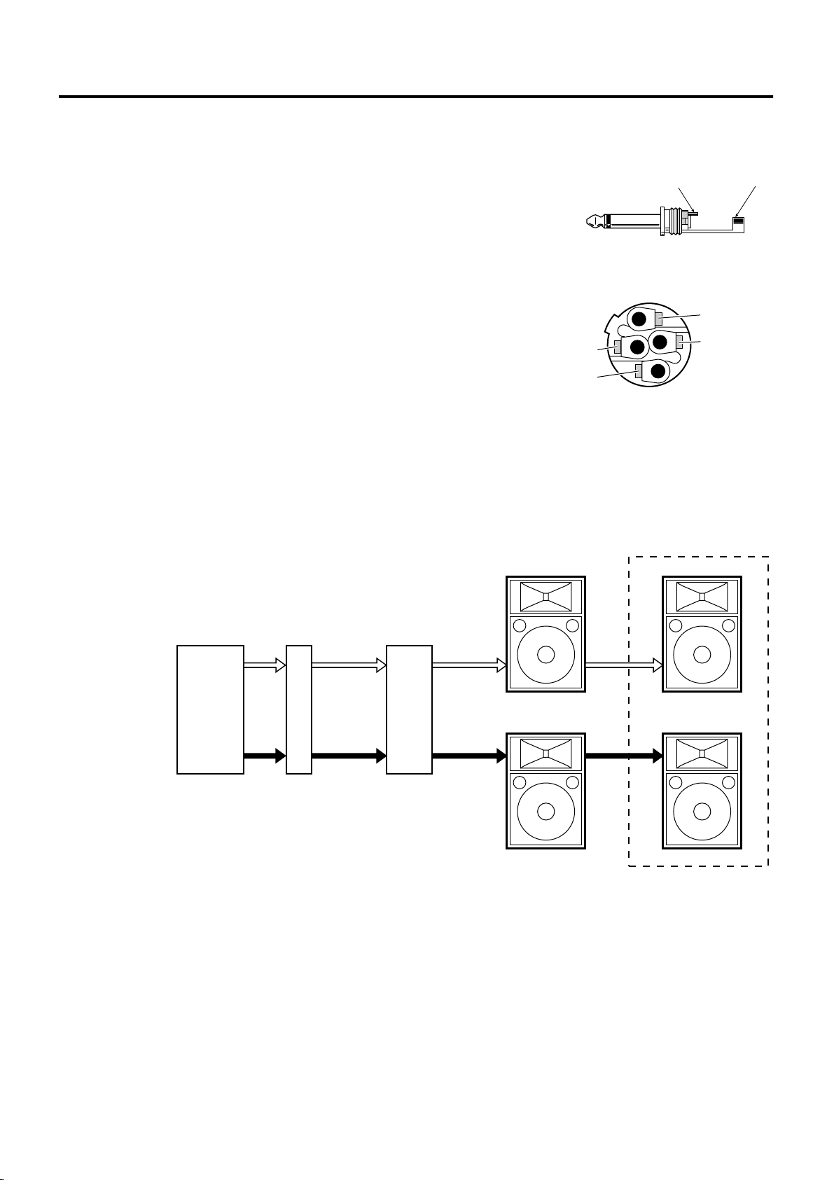
Connecting the Speakers
■ Phone Plug Wiring
Phone plugs for connection to the phone jack inputs should be wired as
shown to the right. Be sure to use proper speaker cable — NOT shielded
instrument or line cable — for all speaker connections.
■ Neutrik Speakon NL4FC Plug Wiring
HOT(+) COLD(–)
If you will be using the Neutrik connectors for speaker input,
wire the plugs as shown to the right. Be sure to use proper speaker
cable — NOT shielded instrument or line cable — for all speaker
connections.
■ Full-range Connection
Each speaker (except for the C112VA/ C115VA) features four input/parallel connectors—two 1/4” phone jacks and
two Neutrik Speakon NL4MP connectors. Use either a phone jack or a Speakon connector to receive input from your
sound system/power amplifier. One of the spare connectors can be used to parallel-connect an additional speaker
(keeping in mind the impedance considerations mentioned below).
MIXING
CONSOLE
L
GRAPHIC
EQUALIZER
2– (NO USE)
1+ : HOT(+)
1– :COLD (–)
Neutrik NL4FC connector
POWER
AMPLIFIER
L
L
SPEAKER
SYSTEMS
2+ (NO USE)
SPEAKER
SYSTEMS
R
R
R
Impedance Considerations
When connecting speakers in parallel be sure to check the rated load impedance of the power amplifier. Most power
amplifiers are capable of safely driving speakers with minimum impedance of 8 ohms or 4 ohms. A pair of parallel-connected 8-ohm speakers have a total impedance of 4 ohms. Two 8-ohm speakers can safely be paralleled on one
output. 4-ohm speakers, however, should not be parallel-connected with other speakers. These models can be connected in parallel, however, if you are using a power amplifier that can safely drive load impedances of 2 ohms or
lower. Check your speaker impedance on page 7.
4
Page 5

■ Subwoofers and the PN90 Crossover Network
Adding subwoofers to speaker systems like the one shown in the diagram can provide extended frequency range and
superior overall sound quality. After dividing the line-level audio from the preamplifier or mixing console into separate frequency bands via the PN90 crossover network, the separate frequency bands are sent to separate power amplifiers.
ENGLISH
MIXING
CONSOLE
L
R
TWO-CHANNEL
GRAPHIC
EQUALIZER
L
INPUTS
RIGHT
R
LEFT
PN90
LEFT
HIGH
RIGHT
TO POWER
AMP INPUTS
LEFT
LOW INPUT
RIGHT
INPUT
TWO-CHANNEL
POWER AMPLIFIER
L
L
OUTPUT
R
R
L
L
OUTPUT
R
R
TWO-CHANNEL
POWER AMPLIFIER
SPEAKER
SYSTEM
SUBWOOFER
SPEAKER
SYSTEM
SUBWOOFER
Precautions for operating the PN90
• Do not connect the PN90 between the power amplifier and speakers. The high voltage levels produced can damage
the PN90.
• Use the PN90 with a load impedance of between 7.5k
• The polarity of the LOW signal is inverted at the crossover point between the LOW and HIGH signals. Compensate for this by reversing the polarity when connecting the power amplifier output jacks to a subwoofer. Note that
you must reverse the polarity between the power amplifier and subwoofers rather than between the PN90 and
power amplifier to prevent damage to the connected device.
• The PN90’s connectors are unbalanced phone jacks. Use shielded audio cable with phone plugs to connect to the
PN90. Do not use speaker cable.
• Adjust the level of the LOW and HIGH signals using the power amplifier volume controls.
Ω and 30kΩ. (Rated load impedance is 15kΩ)
5
Page 6

Suspended and Bracket Installation
• Consult an installation expert to arrange for installation or construction work.
• Choose suspension wire, an installation location, and mounting hardware that are strong enough to support the
weight of the speaker.
• Some fittings may deteriorate over extended periods of time due to wear or corrosion. For safety the installation
should be checked thoroughly at regular intervals.
Yamaha cannot be held responsible for damage or injury caused by insufficient strength of the support structure or improper
installation.
■ Suspended Installation
The C112VA and C115VA can be used in suspended “flying”
rigs by using an appropriate suspension wire.
1. Replace the bolts with the supplied eyebolts (3/8") as shown
in the diagram, and then suspend the speaker using an
appropriate wire.
Bolts
Bolts
Eyebolts
• Use only the supplied eyebolts.
• Use two or more eyebolts for suspended installation. Always use the eyebolts marked .
• Do not suspend a speaker from another suspended
speaker.
Eyebolts
■ Bracket Installation
The C112VA has bracket-mounting screws on the top, bottom,
and sides of the speaker enclosure. The C112VA can be
mounted on a wall or ceiling using the optional brackets listed
below.
Bracket Model
Wall bracket BWS251-300, BWS251-400
Ceiling bracket BCS251
Baton bracket BBS251
Screws (W5/16")
2. The speaker angle can be adjusted for optimum coverage by
adjusting the lengths of the suspension wires, but the downward tilt angle must be less than 45 degrees, as shown in the
diagram.
Maximum
45
Degrees
6
• Use only the specified screws (W5/16")
to attach the bracket to the speaker.
The mounting screws are installed on the speaker
when it leaves the factory. Refer to the instruction manual supplied with your bracket for
installation details.
Page 7

Specifications
Model CM10V C112V C112VA CM12V C115V C115VA CM15V C215V
Enclosure
Speaker Unit
Frequency Response
Power Capacity
Nominal Impedance
Sensitivity
Nominal Dispersion
Crossover Frequency
Input Connectors
Dimensions (W × H × D)
Weight
Included Accessories
LF
HF
NOISE*
PGM
MAX
Horizontal
Vertical
10" cone 12" cone 15" cone 15" cone × 2
1" V.C.driver 2" V.C.driver
70Hz-20kHz 60Hz-16kHz 55Hz-16kHz 42Hz-16kHz
125W 175W 250W 500W
250W 350W 500W 1000W
500W 700W 1000W 2000W
96dB SPL
(1W, 1m)
40˚ 90˚ 90˚ 40˚ 90˚ 90˚ 40˚ 90˚
60˚ 40˚ 40˚ 90˚ 40˚ 40˚ 90˚ 40˚
1.8kHz 2kHz 1.7kHz 1.5kHz
1/4" Phone Jack × 2,
Neutrik Speakon NL4MP × 2
556 × 349
× 273mm
13.3Kg 21.3Kg 21.8Kg 21.8Kg 30.3Kg 29.9Kg 28.8Kg 47.5Kg
——
416 × 628
× 329mm
97dB SPL (1W, 1m) 99dB SPL (1W, 1m)
Barrier Strip
Terminal
416 × 620
× 329mm
Eyebolt
(3/8") × 4
Bass Reflex Type
8Ω 4Ω
1/4" Phone Jack × 2,
Neutrik Speakon NL4MP × 2
628 × 410
× 339mm
——
485 × 715
× 373mm
Barrier Strip
Terminal
485 × 707
× 373mm
Eyebolt
(3/8") × 4
C112V/C112VA /C115V/C115VA CM10V/CM12V/CM15V C215V
99dB SPL
(1W, 1m)
1/4" Phone Jack × 2,
Neutrik Speakon NL4MP × 2
715 × 479
× 339mm
——
491 × 1163
× 593mm
ENGLISH
Model CW115V CW118V CW218V
Enclosure
Speaker Unit
Frequency Response
NOISE*
Power Capacity
Nominal Impedance
Sensitivity
Recommended Crossover Frequency
Input Connectors
Dimensions (W × H × D)
Weight
*: EIA RS-426
PGM
MAX
CW115V/CW118V CW218V
Bass Reflex Type
15" cone 18" cone 18" cone × 2
35Hz-2kHz 30Hz-2kHz
250W 300W 600W
500W 600W 1200W
1000W 1200W 2400W
8Ω 4Ω
95dB SPL (1W, 1m) 96dB SPL (1W, 1m) 98dB SPL (1W, 1m)
90Hz, 12dB/oct.
1/4" Phone Jack × 2, Neutrik Speakon NL4MP × 2
500 × 607 × 528
28Kg 37.2Kg 64.7Kg
mm
605 × 720 × 637
mm
1217 × 574 × 655
mm
Specifications and descriptions
in this owner’s manual are for
information purposes only.
Yamaha Corp. reserves the right
to change or modify products or
specifications at any time without prior notice. Since specifications, equipment or options may
not be the same in every locale,
please check with your Yamaha
dealer.
Unit: mm
7
Page 8

Technical Data/Kennlinien/Données techniques/Datos técnicos
Frequency Response/Impedance
• CM10V • C115V/CM15V/C115VA
110
110
ENGLISH
100
90
80
RESPONSE(dB)
70
60
20
16
8
4
10k1k100
100
RESPONSE(dB)
FREQUENCY(Hz)
• C112V/CM12V/C112VA • C215V
110
100
90
80
RESPONSE(dB)
70
60
20
1k100
FREQUENCY(Hz)
16
8
4
10k
110
100
RESPONSE(dB)
• CW115V • CW118V
110
110
90
80
70
60
90
80
70
60
20
20
FREQUENCY(Hz)
FREQUENCY(Hz)
16
8
4
10k1k100
FRANÇAIS
16
8
DEUTSCH
4
2
10k1k100
ESPAÑOL
• CW218V
100
90
80
RESPONSE(dB)
70
60
20
110
100
90
80
RESPONSE(dB)
70
60
20
1k100
FREQUENCY(Hz)
1k100
FREQUENCY(Hz)
10k
10k
16
100
90
80
RESPONSE(dB)
8
4
70
60
20
16
8
4
10k1k100
FREQUENCY(Hz)
16
8
4
2
33
■
Page 9

■ Horizontal Directivity
• CM10V
• 500Hz
• 1kHz
• 2kHz
330
°
300
°
0°
30°
• 4kHz
0°
330
°
30°
• 8kHz
6
0
°
• 16kHz
300
°
6
0
°
50
40 40302010030 20 10 0
°
270
°
0
4
2
• C112V/CM12V/C112VA
• 500Hz
• 1kHz
• 2kHz
300
°
50
40 40302010030 20 10 0
°
270
°
0
4
2
• C115V/CM15V/C115VA
• 500Hz
• 1kHz
• 2kHz
300
90°
50
120°
°
210
0°
330
°
°
210
330
°
°
°
0
5
1
°
180
30°
6
0
°
90°
50
120°
°
0
5
1
°
180
0°
30°
6
0
°
• 4kHz
• 8kHz
• 16kHz
• 4kHz
• 8kHz
• 16kHz
50
40 40302010030 20 10 0
°
270
°
0
4
2
300
°
50
40 40302010030 20 10 0
°
270
°
0
4
2
300
°
°
210
330
°
210
330
°
°
180
0°
30°
°
°
180
0°
30°
90°
50
120°
°
50
1
6
0°
90°
50
120°
0°
5
1
6
0
°
• C215V
• 500Hz
• 1kHz
• 2kHz
50
40 40302010030 20 10 0
°
270
°
0
4
2
300
°
50
40 40302010030 20 10 0
°
270
°
0
4
2
90°
50
120°
°
210
0°
330
°
°
210
°
0
5
1
°
180
30°
6
0
°
90°
50
120°
°
0
5
1
°
180
• 4kHz
• 8kHz
• 16kHz
50
40 40302010030 20 10 0
°
270
°
0
4
2
300
°
50
40 40302010030 20 10 0
°
270
°
0
4
2
°
210
°
180
0°
330
°
°
210
°
180
90°
50
120°
°
0
5
1
30°
6
0
°
90°
50
120°
°
0
5
1
34
Page 10
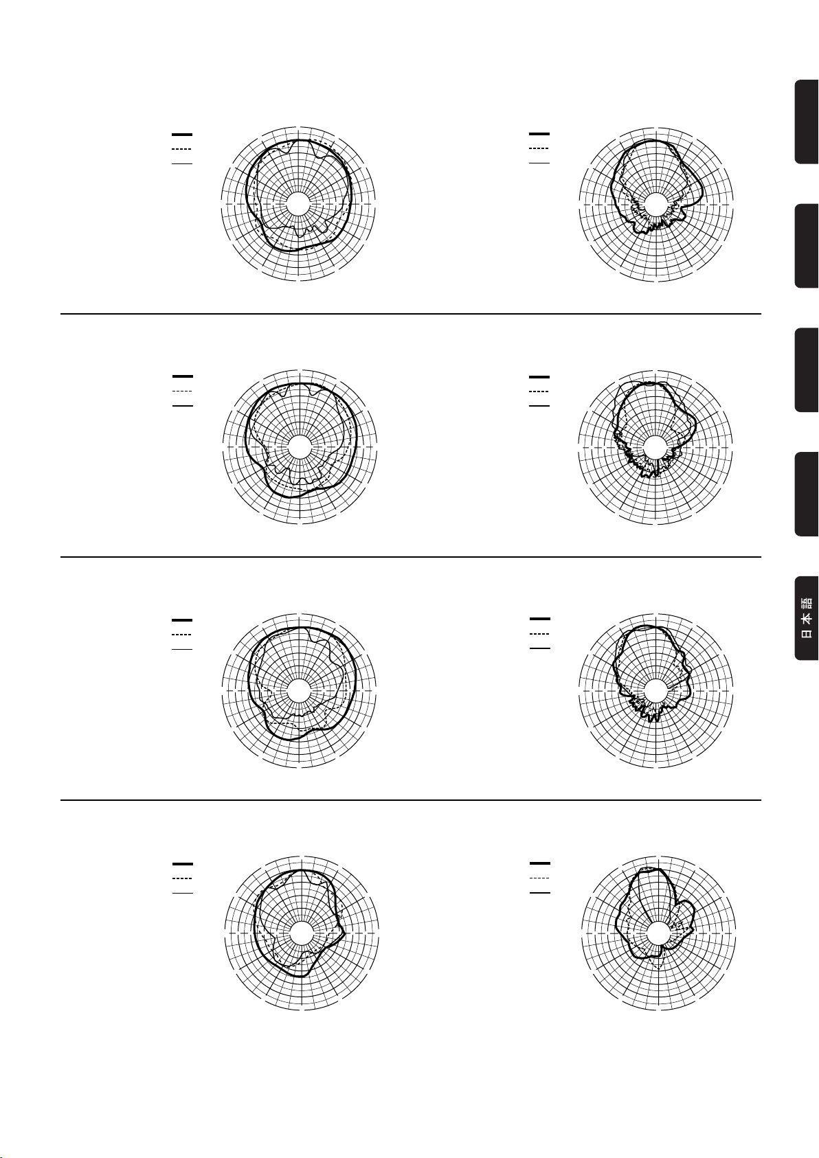
Vertical Directivity
• CM10V
• 500Hz
• 1kHz
• 2kHz
0°
330
°
300
°
30°
6
0
°
• 4kHz
• 8kHz
• 16kHz
300°
0°
330
°
30°
ENGLISH
6
0
°
50
40 40302010030 20 10 0
°
270
°
0
4
2
• C112V/CM12V/C112VA
• 500Hz
• 1kHz
• 2kHz
300
°
50
40 40302010030 20 10 0
°
270
0
4
2
• C115V/CM15V/C115VA
• 500Hz
• 1kHz
• 2kHz
300
°
90°
50
120°
°
210
330
°
°
°
210
330
°
0°
°
180
0°
0°
15
30°
6
0
°
90
°
50
120°
°
0
5
°
180
1
30°
• 4kHz
• 8kHz
• 16kHz
• 4kHz
50
40 40302010030 20 10 0
°
270
°
0
4
2
300
°
50
40 40302010030 20 10 0
°
270
°
0
4
2
°
210
°
180
0°
330
°
°
210
330
°
180
0°
°
90°
50
120°
0°
5
1
30°
6
0
°
90
°
50
120°
°
50
1
30°
DEUTSCH
FRANÇAIS
ESPAÑOL
• 8kHz
6
0
°
• 16kHz
300
°
6
0
°
• C215V
• 500Hz
• 1kHz
• 2kHz
50
40 40302010030 20 10 0
°
270
°
0
4
2
300
°
50
40 40302010030 20 10 0
°
270
°
0
4
2
90°
50
120°
°
210
330
°
°
210
°
0
5
1
°
180
0°
30°
6
0
°
90°
50
120°
°
0
5
1
°
180
• 4kHz
• 8kHz
• 16kHz
50
40 40302010030 20 10 0
°
270
°
0
4
2
300
°
50
40 40302010030 20 10 0
°
270
°
0
4
2
°
210
°
180
0°
330
°
°
210
°
180
90°
50
120°
°
0
15
30°
6
0
°
90°
50
120°
°
0
5
1
35
■
Page 11

For details of products, please contact your nearest Yamaha
representative or the authorized distributor listed below.
Pour plus de détails sur les produits, veuillez-vous adresser à Yamaha ou
au distributeur le plus proche de vous figurant dans la liste suivante.
Die Einzelheiten zu Produkten sind bei Ihrer unten aufgeführten
Niederlassung und bei Yamaha Vertragshändlern in den jeweiligen
Bestimmungsländern erhältlich.
Para detalles sobre productos, contacte su tienda Yamaha más cercana
o el distribuidor autorizado que se lista debajo.
NORTH AMERICA
CANADA
Yamaha Canada Music Ltd.
135 Milner Avenue, Scarborough, Ontario,
M1S 3R1, Canada
Tel: 416-298-1311
U.S.A.
Yamaha Corporation of America
6600 Orangethorpe Ave., Buena Park, Calif. 90620,
U.S.A.
Tel: 714-522-9011
CENTRAL & SOUTH AMERICA
MEXICO
Yamaha de México S.A. de C.V.
Calz. Javier Rojo Gómez #1149,
Col. Guadalupe del Moral
C.P. 09300, México, D.F., México
Tel: 55-5804-0600
BRAZIL
Yamaha Musical do Brasil Ltda.
Av. Reboucas 2636-Pinheiros CEP: 05402-400
Sao Paulo-SP. Brasil
Tel: 011-3085-1377
ARGENTINA
Yamaha Music Latin America, S.A.
Sucursal de Argentina
Viamonte 1145 Piso2-B 1053,
Buenos Aires, Argentina
Tel: 1-4371-7021
PAN AMA AND OTHER LATIN
AMERICAN COUNTRIES/
CARIBBEAN COUNTRIES
Yamaha Music Latin America, S.A.
Torre Banco General, Piso 7, Urbanización Marbella,
Calle 47 y Aquilino de la Guardia,
Ciudad de Panamá, Panamá
Tel: +507-269-5311
EUROPE
THE UNITED KINGDOM
Yamaha-Kemble Music (U.K.) Ltd.
Sherbourne Drive, Tilbrook, Milton Keynes,
MK7 8BL, England
Tel: 01908-366700
GERMANY
Yamaha Music Central Europe GmbH
Siemensstraße 22-34, 25462 Rellingen, Germany
Tel: 04101-3030
SWITZERLAND/LIECHTENSTEIN
Yamaha Music Central Europe GmbH,
Branch Switzerland
Seefeldstrasse 94, 8008 Zürich, Switzerland
Tel: 01-383 3990
AUSTRIA
Yamaha Music Central Europe GmbH,
Branch Austria
Schleiergasse 20, A-1100 Wien, Austria
Tel: 01-60203900
CZECH REPUBLIC/SLOVAKIA/
HUNGARY/SLOVENIA
Yamaha Music Central Europe GmbH,
Branch Austria, CEE Department
Schleiergasse 20, A-1100 Wien, Austria
Tel: 01-602039025
POLAND
Yamaha Music Central Europe GmbH
Sp.z. o.o. Oddzial w Polsce
ul. 17 Stycznia 56, PL-02-146 Warszawa, Poland
Tel: 022-868-07-57
THE NETHERLANDS/
BELGIUM/LUXEMBOURG
Yamaha Music Central Europe GmbH,
Branch Benelux
Clarissenhof 5-b, 4133 AB Vianen, The Netherlands
Tel: 0347-358 040
FRANCE
Yamaha Musique France
BP 70-77312 Marne-la-Vallée Cedex 2, France
Tel: 01-64-61-4000
ITALY
Yamaha Musica Italia S.P.A.
Combo Division
Viale Italia 88, 20020 Lainate (Milano), Italy
Tel: 02-935-771
SPAIN/PORTUGAL
Yamaha-Hazen Música, S.A.
Ctra. de la Coruna km. 17, 200, 28230
Las Rozas (Madrid), Spain
Tel: 91-639-8888
SWEDEN
Yamaha Scandinavia AB
J. A. Wettergrens Gata 1
Box 30053
S-400 43 Göteborg, Sweden
Tel: 031 89 34 00
DENMARK
YS Copenhagen Liaison Office
Generatorvej 6A
DK-2730 Herlev, Denmark
Tel: 44 92 49 00
NORWAY
Norsk filial av Yamaha Scandinavia AB
Grini Næringspark 1
N-1345 Østerås, Norway
Tel: 67 16 77 70
OTHER EUROPEAN COUNTRIES
Yamaha Music Central Europe GmbH
Siemensstraße 22-34, 25462 Rellingen, Germany
Tel: +49-4101-3030
AFRICA
Yamaha Corporation,
Asia-Pacific Music Marketing Group
Nakazawa-cho 10-1, Hamamatsu, Japan 430-8650
Tel: +81-53-460-2313
MIDDLE EAST
TURKEY/CYPRUS
Yamaha Music Central Europe GmbH
Siemensstraße 22-34, 25462 Rellingen, Germany
Tel: 04101-3030
OTHER COUNTRIES
Yamaha Music Gulf FZE
LB21-128 Jebel Ali Freezone
P.O.Box 17328, Dubai, U.A.E.
Tel: +971-4-881-5868
ASIA
THE PEOPLE’S REPUBLIC OF CHINA
Yamaha Music & Electronics (China) Co.,Ltd.
25/F., United Plaza, 1468 Nanjing Road (West),
Jingan, Shanghai, China
Tel: 021-6247-2211
INDONESIA
PT. Yamaha Music Indonesia (Distributor)
PT. Nusantik
Gedung Yamaha Music Center, Jalan Jend. Gatot
Subroto Kav. 4, Jakarta 12930, Indonesia
Tel: 21-520-2577
KOREA
Yamaha Music Korea Ltd.
Tong-Yang Securities Bldg. 16F 23-8 Yoido-dong,
Youngdungpo-ku, Seoul, Korea
Tel: 02-3770-0660
MALAYSIA
Yamaha Music Malaysia, Sdn., Bhd.
Lot 8, Jalan Perbandaran, 47301 Kelana Jaya,
Petaling Jaya, Selangor, Malaysia
Tel: 3-78030900
SINGAPORE
Yamaha Music Asia Pte., Ltd.
#03-11 A-Z Building
140 Paya Lebor Road, Singapore 409015
Tel: 747-4374
TAIWAN
Yamaha KHS Music Co., Ltd.
3F, #6, Sec.2, Nan Jing E. Rd. Taipei.
Taiwan 104, R.O.C.
Tel: 02-2511-8688
THAILAND
Siam Music Yamaha Co., Ltd.
891/1 Siam Motors Building, 15-16 floor
Rama 1 road, Wangmai, Pathumwan
Bangkok 10330, Thailand
Tel: 02-215-2626
OTHER ASIAN COUNTRIES
Yamaha Corporation,
Asia-Pacific Music Marketing Group
Nakazawa-cho 10-1, Hamamatsu, Japan 430-8650
Tel: +81-53-460-2317
OCEANIA
AUSTRALIA
Yamaha Music Australia Pty. Ltd.
Level 1, 99 Queensbridge Street, Southbank,
Victoria 3006, Australia
Tel: 3-9693-5111
COUNTRIES AND TRUST
TERRITORIES IN PACIFIC OCEAN
Yamaha Corporation,
Asia-Pacific Music Marketing Group
Nakazawa-cho 10-1, Hamamatsu, Japan 430-8650
Tel: +81-53-460-2313
PA13
HEAD OFFICE
Yamaha Corporation, Pro Audio & Digital Musical Instrument Division
Nakazawa-cho 10-1, Hamamatsu, Japan 430-8650
Tel: +81-53-460-2441
Ya maha Pro Audio global web site
http://www.yamahaproaudio.com/
Ya m a ha Manual Library
http://www.yamaha.co.jp/manual/
U.R.G., Pro Audio & Digital Musical Instrument Division, Yamaha Corporation
© 2003 Yamaha Corporation
CJY0336 0602CRZC*.*-02B0
Printed in Indonesia
 Loading...