

Page 1

ENGLISH
R
DEUTSCH
FRANÇAIS
IMPORTANT
Check your power supply
Make sure that your local AC
mains voltage matches the voltage specified on the name plate
on the bottom panel. In some areas a voltage selector may be
provided on the bottom panel of
the main keyboard unit near the
power cord. Make sure that the
voltage selector is set for the voltage in your area. The voltage selector is set at 240V when the unit
is initially shipped. To change the
setting use a “minus” screwdriver
to rotate the selector dial so that
the correct voltage appears next
to the pointer on the panel.
WICHTIG
Überprüfung der Stromversorgung
Vergewissern Sie sich vor dem Anschließen an das Stromnetz, daß die
örtliche Netzspannung den
Betriebsspannungswerten auf dem
Typenschild an der Unterseite des Instruments entspricht. In bestimmten
Verkaufsgebieten ist das Instrument
mit einem Spannungswähler an der
Unterseite neben der Netzkabeldurchführung ausgestattet. Falls vorhanden, muß der Spannungswähler
auf die örtliche Netzspannung eingestellt werden. Der Spannungswähler
wurde werkseitig auf 240 V voreingestellt. Zum Verstellen drehen Sie den
Spannungsregler mit einem Schlitzschraubendreher, bis der Zeiger auf
den korrekten Spannungswert weist.
IMPORTANT
Contrôler la source d’alimentation
Vérifiez que la tension spécifiée sur
le panneau arrière correspond à la
tension du secteur. Dans certaines
régions, l’instrument peut être
équipé d’un sélecteur de tension situé sur le panneau inférieur du clavier à proximité du cordon d’alimentation. Vérifiez que ce sélecteur est
bien réglé en fonction de la tension
secteur de votre région. Le sélecteur de tension est réglé sur 240 V
au départ d’usine. Pour modifier ce
réglage, utilisez un tournevis à
lame plate pour tourner le sélecteur
afin de mettre l’indication correspondant à la tension de votre région vis à vis du repère triangulaire
situé sur le panneau.
ESPAÑOL
IMPORTANTE
Verifique la alimentación de
corriente
Asegúrese de que tensión de alimentación de CA de su área corresponde con la tensión especificada en la placa de características del panel inferior de la unidad
del teclado principal, cerca del
cable de alimentación. Asegúrese
de que el selector de tensión esté
ajustado a la tensión de su área.
El selector de tensión se ajusta a
240V cuando la unidad sale de
fábrica. Para cambiar el ajuste,
emplee un destornillador de cabeza “recta” para girar el selector de
modo que aparezca la tensión
correcta al lado del indicador del
panel.
Page 2
SPECIAL MESSAGE SECTION
PRODUCT SAFETY MARKINGS: Yamaha electronic
products may have either labels similar to the graphics
shown below or molded/stamped facsimiles of these
graphics on the enclosure. The explanation of these graphics appears on this page. Please observe all cautions indicated on this page and those indicated in the safety instruction section.
CAUTION
RISK OF ELECTRIC SHOCK
DO NOT OPEN
CAUTION: TO REDUCE THE RISK OF ELECTRIC SHOCK.
DO NOT REMOVE COVER (OR BACK).
NO USER-SERVICEABLE PARTS INSIDE.
REFER SERVICING TO QUALIFIED SERVICE PERSONNEL.
See bottom of Keyboard enclosure for graphic symbol markings
The exclamation point within the equilateral triangle is intended to alert the user to
the presence of important operating and
maintenance (servicing) instructions in the
literature accompanying the product.
ENVIRONMENTAL ISSUES: Yamaha strives to produce products that are both user safe and environmentally
friendly. We sincerely believe that our products and the
production methods used to produce them, meet these
goals. In keeping with both the letter and the spirit of the
law, we want you to be aware of the following:
Battery Notice: This product MAY contain a small nonrechargable battery which (if applicable) is soldered in
place. The average life span of this type of battery is approximately five years. When replacement becomes necessary, contact a qualified service representative to perform the replacement.
Warning: Do not attempt to recharge, disassemble, or
incinerate this type of battery. Keep all batteries away
from children. Dispose of used batteries promptly and as
regulated by applicable laws. Note: In some areas, the
servicer is required by law to return the defective parts.
However, you do have the option of having the servicer
dispose of these parts for you.
Disposal Notice: Should this product become damaged
beyond repair, or for some reason its useful life is considered to be at an end, please observe all local, state, and
federal regulations that relate to the disposal of products
that contain lead, batteries, plastics, etc.
The lightning flash with arrowhead symbol,
within the equilateral triangle, is intended
to alert the user to the presence of
uninsulated “dangerous voltage” within the
product’s enclosure that may be of
sufficient magnitude to constitute a risk of
electrical shock.
IMPORTANT NOTICE: All Yamaha electronic products are tested and approved by an independent safety
testing laboratory in order that you may be sure that when
it is properly installed and used in its normal and customary manner, all foreseeable risks have been eliminated.
DO NOT modify this unit or commission others to do so
unless specifically authorized by Yamaha. Product performance and/or safety standards may be diminished.
Claims filed under the expressed warranty may be denied
if the unit is/has been modified. Implied warranties may
also be affected.
SPECIFICATIONS SUBJECT TO CHANGE: The
information contained in this manual is believed to be
correct at the time of printing. However, Yamaha reserves
the right to change or modify any of the specifications
without notice or obligation to update existing units.
NOTICE: Service charges incurred due to lack of knowledge relating to how a function or effect works (when the
unit is operating as designed) are not covered by the
manufacturer’s warranty, and are therefore the owners
responsibility. Please study this manual carefully and consult your dealer before requesting service.
NAME PLATE LOCATION: The graphic below indicates the location of the name plate. The model number,
serial number, power requirements, etc., are located on
this plate. You should record the model number, serial
number, and the date of purchase in the spaces provided
below and retain this manual as a permanent record of
your purchase.
Model _____________________________________
92-469 1
Serial No. __________________________________
Purchase Date ______________________________
Page 3
PRECAUCIONES
LEER DETENIDAMENTE ANTES DE CONTINUAR
* Guarde estas precauciones en un lugar seguro para su referencia futura.
PRECAUCIÓN
Siempre obedezca las precauciones básicas indicadas abajo para evitar así la posibilidad de lesiones graves o incluso peligro
de muerte debido a descargas eléctricas, incendios u otras contingencias. Estas precauciones incluyen, pero no se limitan, a
los siguientes puntos:
• No abra el instrumento ni trate de desarmar o modificar de
ninguna forma los componentes internos. El instrumento tiene
componentes que no pueden ser reparados por el usuario. En
caso de anormalidades en el funcionamiento, deje de utilizar el
instrumento inmediatamente y hágalo inspeccionar por personal
de servicio calificado de Yamaha.
• No exponga el instrumento a la lluvia, ni lo use cerca del agua o
en lugares donde haya mucha humedad. No ponga recipientes
que contengan líquido encima del instrumento, ya que puede
derramarse y penetrar en el interior del aparato.
• Si el cable o el enchufe de corriente se deteriora o daña, si el
sonido se interrumpe repentinamente durante el uso del
CUIDADO
Siempre obedezca las precauciones básicas indicadas abajo para evitar así la posibilidad de sufrir Ud. u otros lesiones físicas
o de dañar el instrumento u otros objetos. Estas precauciones incluyen, pero no se limitan, a los siguientes puntos:
instrumento o si se detecta olor a quemado o humo a causa de
ello, apague el instrumento inmediatamente, desenchufe el cable
del tomacorriente y haga inspeccionar el instrumento por
personal de servicio calificado de Yamaha.
• Utilice la tensión correcta para su instrumento. La tensión
requerida se encuentra impresa en la placa identificatoria del
instrumento.
• Antes de limpiar el instrumento, desenchufe sin falta el cable de
corriente de la toma de corriente. Jamás enchufe o desenchufe
este cable con las manos mojadas.
• Revise el estado del enchufe de corriente periódicamente o
límpielo siempre que sea necesario.
• No tienda el cable de corriente cerca de fuentes de calor (estufas,
radiadores, etc.), no lo doble demasiado, no ponga objetos
pesados sobre el mismo ni tampoco lo tienda por lugares donde
pueda pasar mucha gente y ser pisado.
• Cuando desenchufe el cable de corriente, hágalo tomándolo del
enchufe y no del cable. Si tira del cable, éste puede dañarse.
• No conecte el instrumento a tomas de corriente usando
conectores múltiples. La calidad de sonido puede verse afectada
o el enchufe puede sobrecalentarse.
• Desenchufe el cable de alimentación eléctrica de la toma de
corriente cuando no vaya a utilizar el instrumento por períodos
de tiempo prolongados y durante tormentas eléctricas.
• Antes de conectar el instrumento a otros componentes
electrónicos, desconecte la alimentación de todos los
componentes. Antes de apagar o encender los componentes,
baje el volumen al mínimo.
• No exponga el instrumento a polvo o vibraciones excesivas ni a
temperaturas extremas (evite ponerlo al sol, cerca de estufas o
dentro de automóviles durante el día), para evitar así la posibilidad
de que se deforme el panel o se dañen los componentes internos.
• No utilice el instrumento cerca de artefactos eléctricos como
televisores, radios o altavoces, ya que éstos pueden causar
interferencias capaces de afectar el correcto funcionamiento de
otros aparatos.
• No ponga el instrumento sobre superficies inestables, donde
pueda caerse por accidente.
• Antes de cambiar el instrumento de lugar, desconecte todos los
cables.
• Para limpiar el instrumento, utilice una paño suave y seco. No
utilice disolventes de pintura, líquidos limpiadores, ni paños
impregnados en productos químicos. Tampoco deje objetos de
vinilo, plástico ni de goma encima del instrumento, ya que pueden
descolorar el panel o el teclado.
• No se apoye con todo el peso de su cuerpo ni coloque objetos
muy pesados sobre los botones, conmutadores o conectores
del teclado.
• No ponga el instrumento pegado contra la pared (deje un espacio
de por lo menos 3 cm/1 pulgada), ya que puede afectar la
circulación de aire y hacer que el instrumento se caliente en
exceso.
• Lea detenidamente la documentación adjunta en la que se
explica el proceso de armado. Si el instrumento no se arma en
el orden correcto, puede dañarse o incluso causar lesiones.
• No utilice el instrumento por mucho tiempo a niveles de volumen
excesivamente altos, ya que ello puede causar pérdida de
audición permanente. Si nota pérdida de audición o si le zumban
los oídos, consulte a un médico.
■USO DEL BANCO (si está incluido)
• No juegue ni se suba al banco. Su uso como herramienta,
escalera o con cualquier otro objetivo puede ser la causa de
accidentes o lesiones.
• En el banco debe sentarse solamente una persona por vez, para
evitar la posibilidad de accidentes o lesiones.
• Si los tornillos del banco se aflojan con el uso, apriételos
periódicamente utilizando la herramienta suministrada.
Yamaha no se responsabiliza por daños debidos a uso
inapropiado o modificaciones hechas al instrumento.
Siempre apague el instrumento cuando no lo usa.
CLP-810S
3
Page 4
Introducción
Enhorabuena por la selección de una Clavinova CLP-810S Yamaha. Su Clavinova es un excelente
instrumento musical que emplea tecnología musical de Yamaha avanzada. Teniendo el cuidado adecuado,
la Clavinova le dará muchos años de placer musical.
● El muestreo estéreo del piano acústico y la
tecnología AWM (memoria avanzada de ondas)
de Yamaha ofrece un realismo una fuerza de
expresión jamás vistos.
● La respuesta a la pulsación semejante a la del
piano, proporciona un gran control de la expre-
● El efecto de reverberación digital añade más
profundidad y expresión al sonido de la
Clavinova.
● Con la compatibilidad MIDI y la amplia gama de
funciones MIDI, la Clavinova puede incorporarse
con facilidad en avanzados sistemas MIDI.
sión y una capacidad excelente de interpretación.
Para aprovechar al máximo el potencial de interpretación y las características de la Clavinova, le aconsejamos que lea completamente este manual de instrucciones y que lo guarde en un lugar seguro para poder
consultarlo en el futuro.
Indice
El panel de control ......................................................................................................... 5
Atril ............................................................................................................................... 6
Para tocar la Clavinova ................................................................................................. 7
Reproducción de las canciones de demostración............................................................. 8
Reverberación................................................................................................................ 9
Los pedales .................................................................................................................... 9
●
Pedal apagador (derecho).......................................................................... 9
●
Pedal suave (izquierdo).............................................................................. 9
Transposición ............................................................................................................... 10
Afinación .......................................................................................................................11
●
Afinación ascendente ................................................................................11
●
Afinación descendente ..............................................................................11
●
Para reponer el tono estándar...................................................................11
Funciones MIDI ............................................................................................................ 12
●
Breve introducción a MIDI ........................................................................ 12
●
Selección de canal de transmisión y recepción MIDI ............................... 12
●
Activación/desactivación de control local ................................................. 13
Localización y reparación de averías............................................................................ 14
Opciones y módulos de expansión ............................................................................... 14
Formato de datos MIDI ............................................................................................. 15
Gráfica de implementación MIDI .............................................................................. 17
Conjunto del soporte del teclado ............................................................................ 18
Especificaciones ....................................................................................................... 24
Accesorios incluidos
● Manual de instrucciones
● Banqueta (incluida u opcional,
dependiendo del destino)
CLP-810S
4
○○○○○○○○○○○○○○○○○○○○○○○○○○○○○○○○○○○○○○○○○○○○○○○○○○○○○○○○
UBICACION DE LA PLACA DE CARACTERISTICAS: La placa de características está situada en el panel inferior. En esta placa se indican el modelo, el
número de serie, la tensión de alimentación, etc. Anote el modelo, el número de
serie, y la fecha de adquisición en los espacios ofrecidos a continuación, y
guwarde este manual como registro permanente de su adquisición.
Modelo
N.° de serie
Fecha de adquisición
Page 5
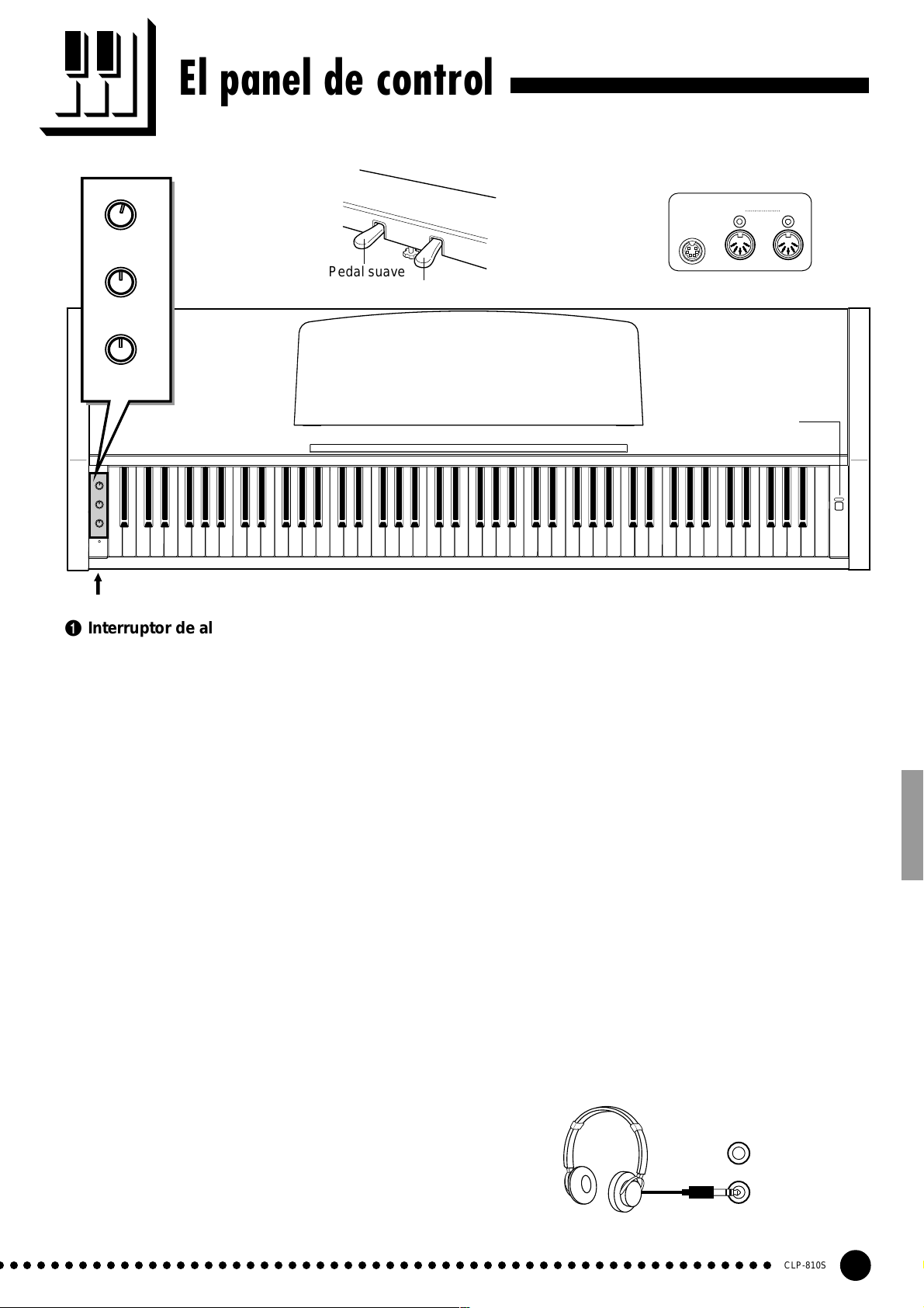
El panel de control
OFF ON
2
VARIATION
Pedal suave
3
MIN MAX
REVERB
4
MIN MAX
MASTER
VOLUME
OFF ON
VARIATION
MIN MAX
REVERB
MIN MAX
MASTER
VOLUME
POWER
8
Tomas PHONES (panel inferior)
C1 D1 E1 F1 G1 A1 B1 C2 D2 E2 F2 G2 A2 B2 C3 D3 E3 F3 G3 A3 B3 C4 D4 E4 F4 G4 A4 B4 C5 D5 E5 F5 G5 A5 B5 C6
B0A0G0F0E0D0C0B-1A-1
1 Interruptor de alimentación [POWER]
Presione el interruptor [POWER] una vez para
conectar la alimentación, y otra vez para desconectarla.
Cuando se conecte la alimentación, se encenderá el
indicador POWER (situado a la izquierda del teclado).
2 Selector de variación [VARIATION]
Con el selector [VARIATION] en la posición OFF,
la CLP-810S produce la voz de piano normal. En la
posición ON, se produce una variación de la voz de
piano (página 7).
3 Control de reverberación [REVERB]
El control [REVERB] ajusta la cantidad de reverberación que se añade al sonido de la Clavinova; para más
detalles, vea la página 9.
4 Control de volumen principal [MASTER
VOLUME]
El control [MASTER VOLUME] ajusta el volumen
(el nivel) del sonido producido por el sistema de sonido
estéreo interno de la Clavinova. El control [MASTER
VOLUME] ajusta también el volumen de los auriculares cuando se han enchufado unos auriculares a la toma
PHONES (página 7).
5
Pedal apagador
6 Toma de PEDAL
7 Conectores MIDI (IN, OUT)
8 Tomas de auriculares (PHONES)
Panel posterior
MIDI
IN OUT
PEDAL
67
1
POWER
D6 E6 F6 G6 A6 B6 C7
Este terminal sirve para conectar el cable del pedal
desde la caja de pedales (consulte el apartado “Montaje
del soporte del teclado” en la página 22).
El conector MIDI recibe los datos MIDI desde un
dispositivo MIDI externo (como por ejemplo la unidad
de discos orquestales Yamaha DOU-10) que pueden
utilizarse para controlar la Clavinova. El conector MIDI
OUT transmite los datos MIDI generados por la
Clavinova (por ejemplo, los datos de velocidad y notas
producidos al tocar el teclado de la Clavinova).
En la sección de “Funciones MIDI”, de la página 12,
se dan más detalles sobre MIDI.
(panel inferior)
Pueden enchufarse dos pares de auriculares estéreo
estándar a estas tomas para la práctica en privado o para
tocar a altas horas de la noche. El sistema de altavoces
interno se desconecta automáticamente cuando se
enchufan unos auriculares a una de las tomas PHONES.
5 Pedales
Los pedales de suave (izquierdo) y apagador (derecho) de la CLP-810S proporcionan una serie de posibilidades de control de la expresión similares a las de un
piano acústico. Vea la página 9- para más detalles.
○ ○○○○○○○○○○○○○○○○○○○○○○○○○○○○○○○○○○○○○○○○○○○○○○○○○○○○○○○
CLP-810S
5
Page 6
Atril
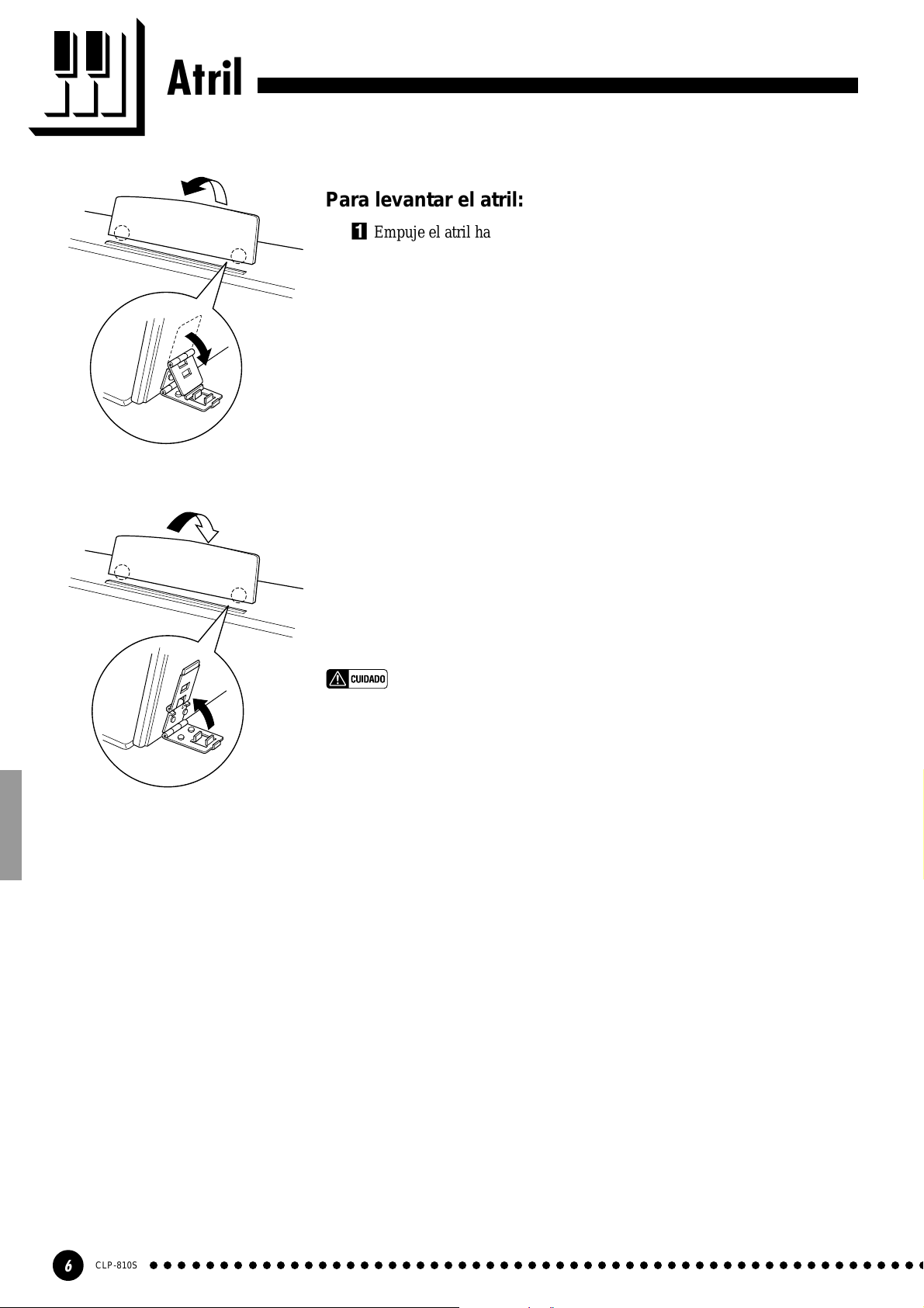
Para levantar el atril:
ZEmpuje el atril hacia arriba y hacia usted por completo.
XBaje los dos soportes metálicos de la izquierda y derecha de la parte
posterior del atril.
CBaje el atril de modo que se apoye en los soportes metálicos.
Como se muestra en la ilustración, el ángulo del atril puede ajustarse en una
de las tres posiciones, de acuerdo con la posición de los soportes metálicos.
Ajuste los soportes metálicos izquierdo y derecho en la misma posición.
Para bajar el atril:
ZEmpuje el atril hacia usted por completo.
XLevante los dos soportes metálicos (de la parte posterior del atril).
CBaje con cuidado el atril hacia atrás hasta que haya bajado por completo.
• No intente utilizar el atril en una posición medio levantada.
Cuando baje el atril, no lo suelte hasta que haya bajado por completo.
CLP-810S
6
○○○○○○○○○○○○○○○○○○○○○○○○○○○○○○○○○○○○○○○○○○○○○○○○○○○○○○○○
Page 7
Para tocar la Clavinova
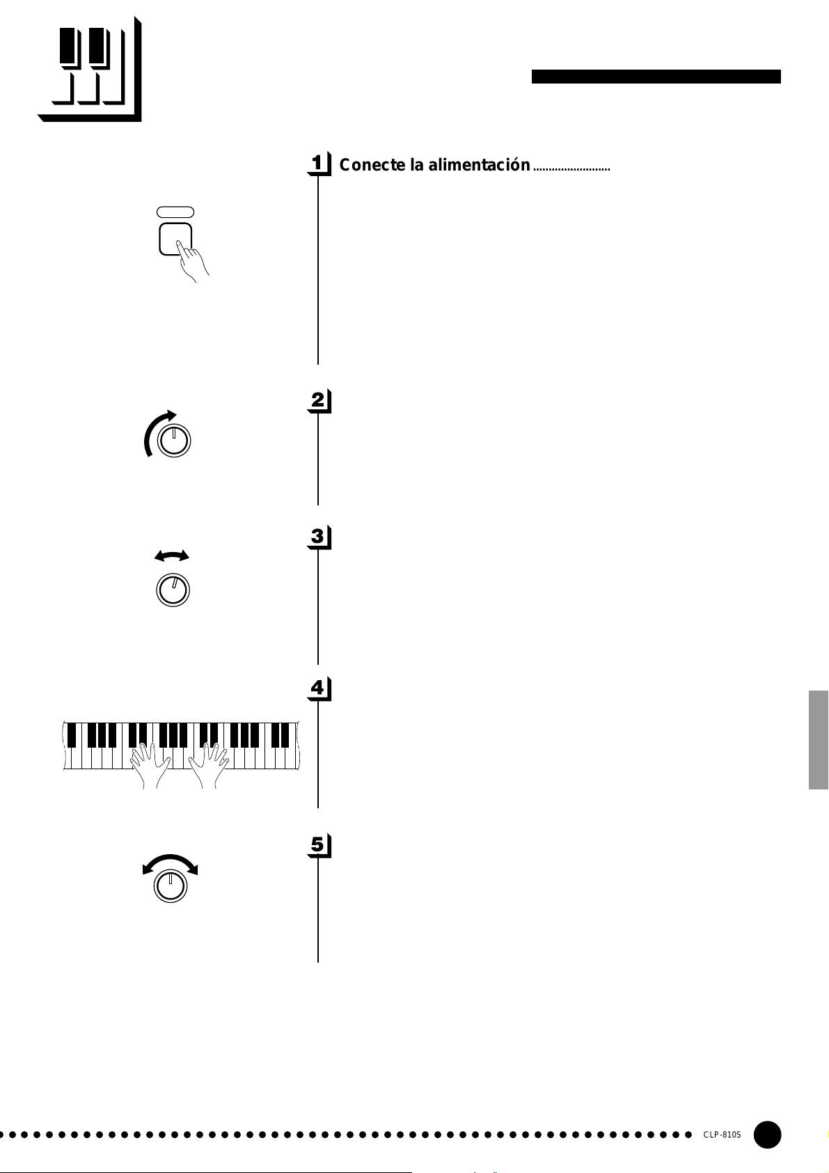
Conecte la alimentación..............................................................................
Después de asegurarse de que la clavija de CA de la Clavinova está
POWER
MIN MAX
MASTER
VOLUME
correctamente enchufada a la misma Clavinova y en un tomacorriente de
CA adecuado, presione el interruptor [POWER], situado a la derecha del
teclado, para conectar la alimentación. En algunas zonas puede suministrarse un adaptador de clavija para adaptarla a la configuración de los
tomacorrientes de CA de la localidad.
Cuando se haya conectado la alimentación, se encenderá el indicador
POWER situado a la izquierda del teclado.
Ajuste el volumen .............................................................................................
Ajuste inicialmente el control [MASTER VOLUME] a una posición
intermedia entre “MIN” y “MAX”, Luego, cuando empiece a tocar,
reajuste la posición del control [MASTER VOLUME] al nivel de audición más adecuado.
OFF ON
VARIATION
MIN MAX
REVERB
Seleccione la voz normal o la variación .......................................
Emplee el selector [VARIATION] para seleccionar la voz normal o la
variación de la Clavinova.
En la posición OFF, se selecciona la voz de piano normal del teclado.
En la posición ON, se selecciona una variación de la voz de piano del
teclado.
Toque............................................................................................................................
La Clavinova ofrece respuesta a la pulsación del teclado, para que el
volumen y el timbre de las notas tocadas pueda controlarse de acuerdo con
la fuerza aplicada al tocar las teclas.
Añada la reverberación necesaria .....................................................
Con el control [REVERB] podrá añadir la cantidad deseada de reverberación al sonido de la Clavinova (página 9).
○ ○○○○○○○○○○○○○○○○○○○○○○○○○○○○○○○○○○○○○○○○○○○○○○○○○○○○○○○
CLP-810S
7
Page 8
A-1C
Reproducción de las canciones de demostración
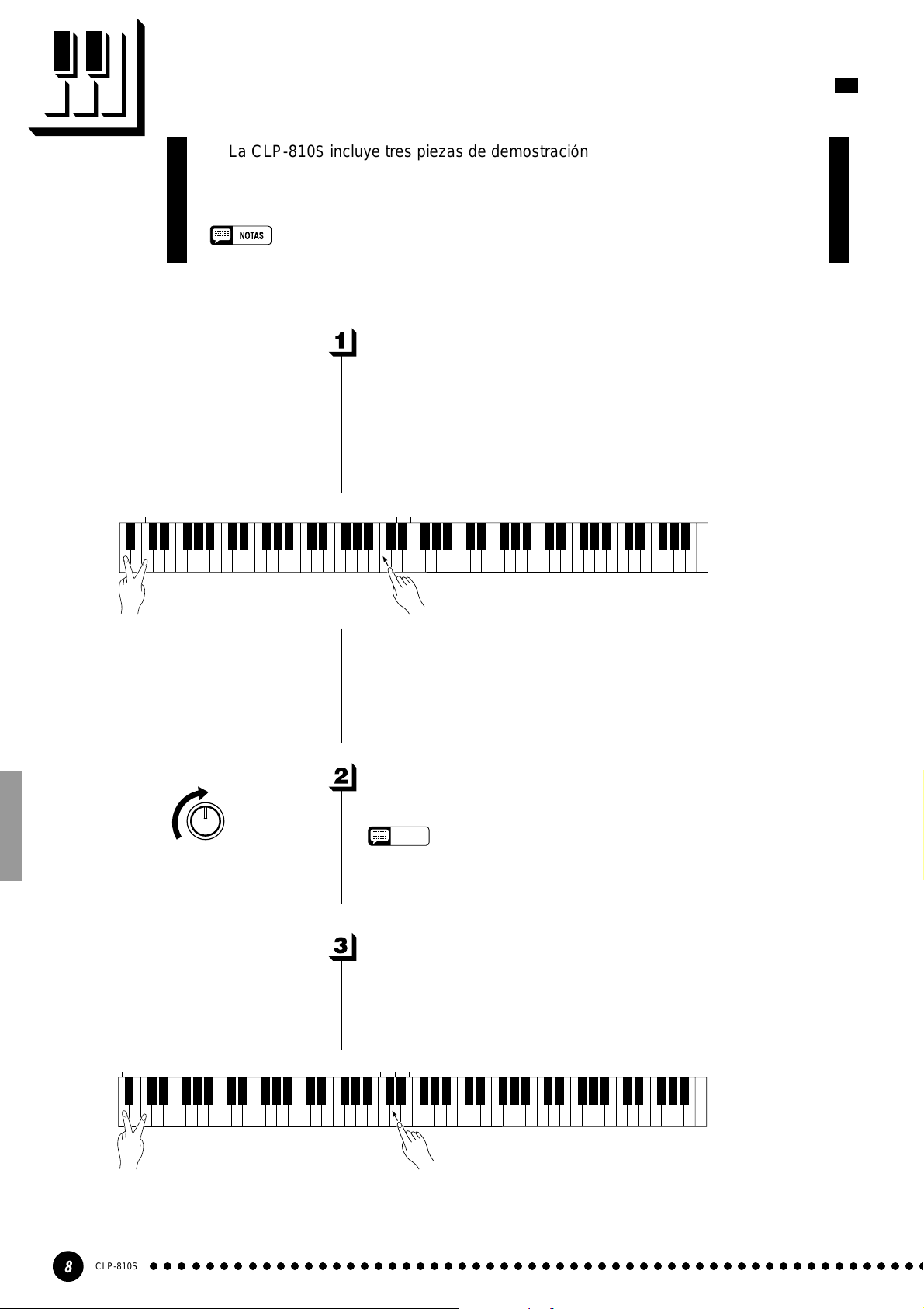
La CLP-810S incluye tres piezas de demostración que demuestran sus posibilidades sonoras. A continuación se indica cómo puede seleccionar y reproducir las
canciones de demostración:
• No se reproduce ninguna recepción MIDI en el modo de demostración.
• Los datos de la canción de demostración no se transmiten a través de los conectores MIDI.
Seleccione una pieza de demostración.........................................
Mientras presionan simultáneamente las teclas A-1 y C0, presione C3,
D3, o E3 para seleccionar e iniciar la pieza de demostración correspon-
diente. Empezando por la pieza seleccionada, las piezas de demostración se
reproducirán en secuencia hasta que se paren.
0
C3D3E
3
A-1C
0
MIN MAX
MASTER
VOLUME
● Las canciones de demostración
• Tecla C3: ...Fantaisie Impromptu / F.F.Chopin
• Tecla D3: ...Für Elise / L.v.Beethoven
• Tecla E3: ... Perpetuum mobile (Sonata No.1) / C.M.v.Weber
Ajuste el volumen .............................................................................................
Utilice el control [MASTER VOLUME] para ajustar el volumen.
NOTE
• Usted podrá tocar el teclado al mismo tiempo que se reproduce la pieza
de demostración.
Detenga la demostración ...........................................................................
Para detener la reproducción de la pieza de demostración, mantenga
presionadas simultáneamente las teclas A-1 y C0, y presione cualquiera de
las teclas C3, D3, o E3. La reproducción de la pieza de demostración se
parará.
3
C3D3E
CLP-810S
8
○○○○○○○○○○○○○○○○○○○○○○○○○○○○○○○○○○○○○○○○○○○○○○○○○○○○○○○○
Page 9
Reverberación
El control [REVERB] le permitirá ajustar la cantidad de efecto de reverberación
digital que se añade al sonido para conseguir mayor profundidad y fuerza de expresión.
Ajuste la profundidad de reverberación empleando el control
[REVERB]. El margen de profundidad es de MIN a MAX. El ajuste MIN
MIN MAX
REVERB
no produce ningún efecto, y el ajuste MAX produce la máxima profundidad de reverberación.
Pedal suave
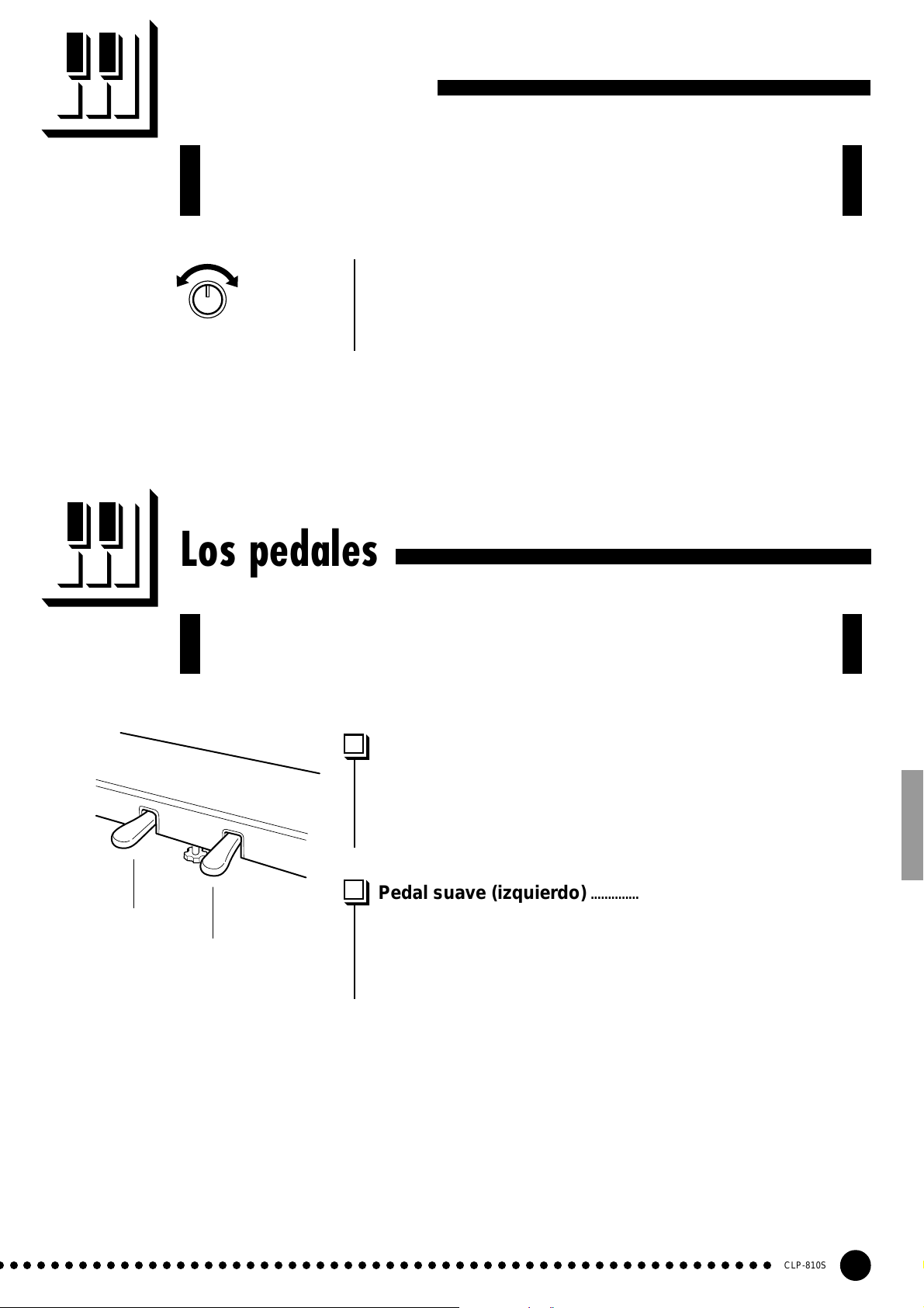
Los pedales
La CLP-810S tiene dos pedales que producen una gama de efectos de expresión similares a los producidos por los pedales de un piano acústico.
Pedal apagador (derecho) .........................................................................
El pedal apagador funciona del mismo modo que el pedal apagador de
un piano acústico. Cuando se pisa el pedal apagador, las notas tocadas
tienen un sostenido largo. Al soltar el pedal, el sostenido de las notas se
detiene (apaga) inmediatamente.
Pedal suave (izquierdo) ...............................................................................
Presionando el pedal suave se reduce el volumen y se cambia ligeramente
Pedal apagador
el timbre de las notas tocadas. El pedal suave no afecta las notas que ya se
están tocando cuando se pisa.
○ ○○○○○○○○○○○○○○○○○○○○○○○○○○○○○○○○○○○○○○○○○○○○○○○○○○○○○○○
CLP-810S
9
Page 10

Transposición
La función TRANSPOSE de la Clavinova hace posible desplazar todo el teclado
ascendente o descendentemente en intervalos de semitono hasta un máximo de
seis semitonos. La “transposición” del tono del teclado de la Clavinova facilita la
interpretación en claves difíciles, y podrá adaptar con facilidad el tono del teclado al
alcance del cantante u otro instrumento.
Las teclas A-1 y C#0 más las teclas F#2 a F#3 del teclado se emplean para la transposición.
ZPresione simultáneamente y mantenga presionadas las teclas A-1 y
C#0.
XPresione cualquier tecla entre F#2 y F#3 de acuerdo con la cantidad
deseada de transposición.*
CSuelte las teclas A-1 y C#0.
3
C
A-1C#
F#
0
2
F#
3
Tono
normal
+3 +6
Transposición
ascendente
-6 -4 -2 +1
-5 -3 -1 0 +2 +4 +5
Transposición
dencendente
* Al presionar la tecla C3 se produce el tono normal del teclado. Al
presionar la tecla de la izquierda de C3 (=B2) se transpone el tono del
teclado un semitono descendentemente, presionand la tecla siguiente de
la izquierda (=Bb2) se transpone descendentemente un tono entero (dos
semitonos), etc. hasta la tecla F#2 que transpone el teclado
descendentemente 6 semitonos. La transposición ascendente se realiza
del mismo modo empleando las teclas de la derecha de C3 hasta F#3
que transpone ascendentemente 6 semitonos.
• Las notas de debajo y encima de A-1 — C7 de la Clavinova suenan una
octava más alta y más baja, respectivamente.
10
CLP-810S
○○○○○○○○○○○○○○○○○○○○○○○○○○○○○○○○○○○○○○○○○○○○○○○○○○○○○○○○
Page 11

A-1B
Afinación
La afinación hace posible afinar el tono de la Clavinova por un margen de 427,0
Hz a 453,0 Hz (correspondiente a los Hz de la nota A3) en intervalos de 0,2 hertz
aproximadamente. El control del tono es útil para afinar la Clavinova para adaptarla
a otros instrumentos o música grabada.
-1
Afinación ascendente....................................................................................
ZPara afinar ascendentemente (aumentar el tono), mantenga presionadas
simultáneamente las teclas A-1 y B-1.
XPresione cualquier tecla entre C3 y B3. Cada vez que se presione una
tecla de este margen, el tono se aumentará aproximadamente 0,2 Hz.
CSuelte las teclas A-1 y B-1.
3
3
C
B
A#
-1
A
A#
A-1B
Afinación descendente ................................................................................
ZPara afinar descendentemente (reducir el tono), mantenga presionadas
simultáneamente las teclas A-1 y A#-1.
XPresione cualquier tecla entre C3 y B3. Cada vez que se presione una
tecla de este margen, el tono se reducirá aproximadamente 0,2 Hz.
CSuelte las teclas A-1 y A#-1.
-1
3
C
3
B
Para reponer el tono estándar*.............................................................
ZPara reponer el tono de ajuste inicial (A3 = 440 Hz), mantenga presio-
nadas simultáneamente las teclas A-1, A#-1 y B-1.
XPresione cualquier tecla entre C3 y B3.
CSuelte las teclas A-1, A#-1 y B-1.
* El tono estándar (A3 = 440 Hz) se ajusta cuando se conecta la alimenta-
ción con el interruptor [POWER].
-1
-1
3
C
3
B
○ ○○○○○○○○○○○○○○○○○○○○○○○○○○○○○○○○○○○○○○○○○○○○○○○○○○○○○○○
CLP-810S
11
Page 12

Funciones MIDI
● Breve introducción a MIDI
Cable MIDI
Datos que se están grabando
Datos de reproducción
MIDI INMIDI OUT
MIDI IN MIDI INMIDI OUTMIDI OUT
DOU-10
Clavinova
MIDI, la Interfaz Digital de Instrumentos Musicales, es una
interfaz de comunicaciones mundial que permite a los instrumentos y equipos musicales compatibles con MIDI compartir la
información musical y controlarse entre sí. Las capacidades de
MIDI hacen posible crear “sistemas” de instrumentos y equipos
MIDI que ofrezca mayor versatilidad y control que el disponible
con componentes individuales. Por ejemplo, la mayor parte de
teclados MIDI (incluyendo la Clavinova, naturalmente)
trasnmiten la información de notas y velocidad (respuesta de
pulsación) a través del conector MIDI OUT siempre que se toca
una nota en el teclado. Si el conector MIDI OUT está conectado
al conector MIDI IN de un segundo teclado (sintetizador, etc.) o
generador de tonos (esencialmente un sintetizador sin teclado), el
segundo teclado o generador de tonos responderá con precisión a
las notas tocadas en el teclado de transmisión original. El
resultado es que usted podrá tocar con efectividad dos instrumentos a la vez, proporcionando sonidos de instrumentos múltiples.
DOU-10
Clavinova
Este mismo tipo de transferencia de información musical se
usa para la grabación de sencuencias MIDI. Una grabadora de
secuencias puede utilizarse para “grabar” datos MIDI recibidos
desde una Clavinova, por ejemplo. Cuando se reproducen los
datos grabados, la Clavinova “reproduce” automáticamente la
interpretación grabada con detalle preciso.
Los ejemplos dados arriba en realidad sólo tocan la superficie.
MIDI puede hacer muchísimo más. La CLP-810S ofrece cierto
número de funciones MIDI que permiten utilizarlo en sistemas
MIDI bastante sofisticados.
• Emplee siempre un cable MIDI de alta calidad para
conectar los terminales MIDI OUT a MIDI IN. No
emplee nunca cables MIDI más largos de unos 15
pies, porque los cables más largos pueden captar
ruido, lo cual puede ocasionar errores de datos.
Selección de canal de transmisión y recepción MIDI......................................................................................
MIDI OUT
DOU-10
MIDI IN MIDI THRU
Generador de tonos
(Ajustado para recibir
en el canal 2 MIDI)
MIDI IN
Clavinova
(Ajustado para recibir en el canal 1 MIDI)
El sistema MIDI permite la transmisión y recepción de datos
MIDI en 16 canales distintos. Se han implementado canales múltiples para permite el control selectivo de ciertos instrumentos o
dispositivos conectados en serie. Por ejemplo, una sola grabadora de
secuencias MIDI puede usarse para “tocar” dos instrumentos o
generados de tonos distintos. Uno de los instrumentos o generadores
de tonos podría ajustarse para recibir sólo en el canal 1, mientras que
el otro para recibir en el canal 2. En esta situación, el primer
instrumento o generador de tonos responderá sólo a la información
del canal 1 transmitida por la grabadora de secuencias, mientras que
el segundo instrumento o generador de tonos responderá sólo a la
información del canal 2. Esto permite a la grabadora de secuencias
“tocar” dos partes completamente distintas en los instrumentos o
generadores de tonos de recepción.
En cualquier disposición de control MIDI, los canales MIDI del
equipo de transmisión y de recepción deben corresponderse para la
transmisión adecuada de los datos. Hay también disponible un modo
de recepción “ALL”, que permite la recepción en todos los 16 canales
MIDI.
12
CLP-810S
○○○○○○○○○○○○○○○○○○○○○○○○○○○○○○○○○○○○○○○○○○○○○○○○○○○○○○○○
Page 13

Funciones MIDI
● Ajuste de los canales MIDI de la Clavinova
0
A-1C#
1
C
2 4 7 9 11 14 16 2 4 7 9 11 14 16
1356810121315 1356810121315
Para ajustar el canal de
transmisión. (C1 - D#2)
ZPresione simultáneamente y mantenga presionadas las teclas A-1 y C#0.
XPresione la tecla del teclado que corresponda al canal MIDI* deseado de transmi-
sión o recepción.
CSuelte las teclas A-1 y C#0.
* Las teclas C1 a D#2 del teclado se emplean para el canal de transmisión MIDI. La
tecla E2 desactiva (“OFF”) la transmisión si usted no desea que la Clavinova
transmita datos MIDI. Las teclas C4 a D#5 se emplean para ajustar el canal de
recepción MIDI como se muestra en la ilustración de abajo. La tecla E5 ajusta el
modo de recepción a “ALL”.
• Cuando se conecta la alimentación, la recepción MIDI se ajusta al modo
ALL y el canal de transmisión se ajusta al 1.
2
D#
E
2
OFF
4
C
Para ajustar el canal de
recepción. (C4 - D#5)
Para modo el ALL
D#
5
E
5
Activación/desactivación de control local.................................................................................................................
El “control local” se refiere al hecho de que, normalmente, el teclado de la
Clavinova controla su generador de tonos interno, permitiendo que las voces internas
MIDI OUT
MIDI
IN
puedan reproducirse directamente desde el teclado. Esta situación es “Activación de
control local” porque el generador de tonos interno está controlado localmente por su
DOU-10
propio teclado.
Sin embargo, el control local puede desactivarse para que el teclado de la Clavinova
Clavinova
no toque las voces internas, pero que la información MIDI apropiada se siga transmitiendo a través del conector MIDI OUT cuando se tocan las teclas en el teclado. Al
mismo tiempo, el generador de tonos responde a la información MIDI recibida a través
del conector MIDI IN.
Cuando se utiliza la unidad de discos orquestales Yamaha DOU-10 con la
Clavinova, por ejemplo, el control local debe desactivarse para grabar empleando sólo
las voces del DOU-10, y activarse cuando se graben las voces de la Clavinova mientras
se escucha la reproducción de las voces del DOU-10.
ZPresione simultáneamente y mantenga presionadas las teclas A-1 y C#0.
XPresione la tecla C6 para cambiar el control local entre OFF y ON.
CSuelte las teclas A-1 y C#0.
• Cuando se conecta la alimentación, el control local se ajusta a “ON”.
6
A-1C#
0
C
○ ○○○○○○○○○○○○○○○○○○○○○○○○○○○○○○○○○○○○○○○○○○○○○○○○○○○○○○○
CLP-810S
13
Page 14

Localización y reparación de averías
Si se encuentra con algo que parece ser un mal funcionamiento, compruebe los
puntos siguientes antes de pensar que ha ocurrido una avería en la Clavinova.
1.No hay sonido cuando se conecta la alimentación
¿Está la clavija de CA correctamente enchufada a la Clavinova y al tomacorriente de CA? Compruebe con
cuidado la conexión de la alimentación de CA. ¿Está el control MASTER VOLUME ajustado a un nivel de
audición razonable?
Asegúrese también que no se hayan enchufado auriculares a la toma PHONES y que el control local (página
13) esté activado (ON).
2.El pedal apagador no funciona
Si el pedal apagador no funciona, o si las notas se sostienen incluso cuando no se pisa el pedal, asegúrese de
que el cable del pedal esté correctamente enchufado en la unidad principal (página 22).
3.La Clavinova reproduce sonido de la radio o TV
Esto puede ocurrir si hay un transmisor de alta potencia en su vecindad. Póngase en contacto con el distribuidor de Yamaha.
4.Ruido estático intermitente
Normalmente se debe a la conexión o desconexión de un electrodoméstico u otro equipo electrónico que se
alimenta con la misma línea de la red de CA que la Clavinova.
5.Aparecen interferencias en la radio o televisor situados cerca de la Clavinova
La Clavinova contiene circuitos digitales que pueden generar ruido de radiofrecuencia. La solución es
apartando la Clavinova del equipo afectado, o viceversa.
Opciones y módulos de expansión
● Opciones
Banqueta BC-8
Es una banqueta cómoda que coordina bien con la Clavinova Yamaha.
Auriculares estéreo HPE-160
Auriculares dinámicos de alto rendimiento y poco peso con almohadillas muy blandas para el oído.
Cubierta de teclado KC-883
Util para mantener el teclado limpio y libre de polvo.
● Módulos de expansión
DOU-10 Unidad de discos orquestales
Una amplia gama de funciones de grabación y reproducción MIDI, más capacidad de reproducción de la
DOC de Yamaha, Disklavier PianoSoft™, y de discos de archivos MIDI General/MIDI estándar.
14
CLP-810S
○○○○○○○○○○○○○○○○○○○○○○○○○○○○○○○○○○○○○○○○○○○○○○○○○○○○○○○○
Page 15

MIDI Data Format/MIDI-Datenformat/
Format des données MIDI/Formato de datos MIDI
If you’re already very familiar with MIDI, or are using a
computer to control your music hardware with computergenerated MIDI messages, the data provided in this section
can help you to control the Clavinova.
Falls Sie bereits mit MIDI vertraut sind oder einen Computer zur Erzeugung von MIDI-Steuermeldungen für die
Instrumente verwenden, können Sie sich zur Steuerung des
Clavinovas nach den im folgenden Abschnitt aufgeführten
Spezifikationen richten.
1 . NOTE ON/OFF
Data format: [9nH] -> [kk] -> [vv]
9nH = Note ON/OFF event (n = channel number)
kk = Note number (Transmit: 09H ~ 78H = A-2 ~ C8 /
Receive: 00H ~ 7FH = C-2 ~ G8)*
vv = Velocity (Key ON = 01H ~ 7FH, Key OFF = 00H)
Data format: [8nH] -> [kk] -> [vv] (reception only)
8nH = Note OFF event (n = channel number)
kk = Note number: 00H ~ 7FH = C-2 ~ G8
vv = Velocity
* If received value exceeds the supported range for the selected
voice, the note is adjusted by the necessary number of octaves.
2 . CONTROL CHANGE
Data format: [BnH] -> [cc] -> [vv]
BnH = Control change (n = channel number)
cc = Control number
vv = Data Range
(1) Bank Select
ccH Parameter Data Range (vvH)
00H Bank Select MSB 00H:Normal
20H Bank Select LSB 00H...7FH
Bank selection processing does not occur until receipt of next Program Change message.
(2) Main Volume (reception only)
ccH Parameter Data Range (vvH)
07H Volume MSB 00H...7FH
(3) Expression
ccH Parameter Data Range (vvH)
0BH Expression MSB 00H...7FH
(4) Damper
ccH Parameter Data Range (vvH)
40H Damper MSB 00H...7FH
(5) Soft Pedal
ccH Parameter Data Range (vvH)
43H Soft Pedal 00H-3FH:off, 40H-7FH:on
(6) Effect1 Depth ( Reverb Send Level )
ccH Parameter Data Range (vvH)
5BH Effect1 Depth 00H...7FH
Adjusts the reverb send level.
3 MODE MESSAGES
Data format: [BnH] -> [cc] -> [vv]
BnH = Control event (n = channel number)
cc = Control number
vv = Data Range
(1) All Sound Off
ccH Parameter Data Range (vvH)
78H All Sound Off 00H
Switches off all sound from the channel. Does not reset Note On and
Hold On conditions established by Channel Messages.
(2) Reset All Controllers
ccH Parameter Data Range (vvH)
79H
Reset All Controllers
Resets controllers as follows.
Controller Value
Expression 127 (max)
Damper Pedal 0 (off)
Sostenuto 0 (off)
Soft Pedal 0 (off)
00H
Si vous êtes très familier avec l’interface MIDI ou si vous
utilisez un ordinateur pour commander votre matériel de
musique au moyen de messages MIDI générés par
ordinateur, les données suivantes vous seront utiles et vous
aideront à commander le Clavinova.
SI usted está ya familiarizado con MIDI, o si emplea una
computadora para controlar sus aparatos musicales con
mensajes MIDI generados por computadora, los datos proporcionados en esta sección le ayudarán a controlar la Clavinova.
(3) Local Control (reception only)
ccH Parameter Data Range (vvH)
7AH Local Control 00H (off), 7FH (on)
(4) All Notes Off
ccH Parameter Data Range (vvH)
7BH All Notes Off 00H
Switches OFF all the notes that are currently ON on the specified
channel. Any notes being held by the damper pedal will continue to
sound until the pedal is released.
(5) Omni Off (reception only)
ccH Parameter Data Range (vvH)
7CH Omni Off 00H
Same processing as for All Notes Off.
(6) Omni On (reception only)
ccH Parameter Data Range (vvH)
7DH Omni On 00H
Same processing as for All Notes Off.
(7) Mono (reception only)
ccH Parameter Data Range (vvH)
7EH Mono 00H
Same processing as for All Sound Off.
(8) Poly (reception only)
ccH Parameter Data Range (vvH)
7FH Poly 00H
Same processing as for All Sound Off.
• When a voice bank MSB/LSB is received, the number is stored in
the internal buffer regardless of the received order, then the stored
value is used to select the appropriate voice when a program
change message is received.
• The Multi-timbre and Poly modes are always active. No change
occurs when OMNI ON, OMNI OFF, MONO, or POLY mode messages are received.
4. PROGRAM CHANGE
Data format: [CnH] -> [ppH]
CnH = Program event (n = channel number)
ppH = Program change number
Program change number
Vioce Bank MSB Bank LSB
PIANO 0 112 0
PIANO (Variation) 0 113 0
Program Change Number
5. SYSTEM REALTIME MESSAGES
Active sensing
[FEH]
• Transmitted every 200 milliseconds.
• If a signal is not received via MIDI for more than 400 milliseconds,
the same processing will take place for All Sound Off, All Notes Off
and Reset All Controllers as when those signals are received.
• Caution: If an error occurs during MIDI reception, the Damper and Soft
effects for all channels are turned off and an All Note Off occurs.
6. SYSTEM EXCLUSIVE MESSAGES
(Universal System Exclusive)
(1) Universal Realtime Message
Data format: [F0H] -> [7FH] -> [XnH] -> [04H] -> [01H] ->
[llH] -> [mmH] -> [F7H]
CLP-810S
15
Page 16

MIDI Data Format/MIDI-Datenformat/Format des données MIDI/Formato de datos MIDI
MIDI Master Volume
• Simultaneously changes the volume of all channels.
• When a MIDI master volume message is received, the volume
only has affect on the MIDI receive channel, not the panel master
volume.
F0H = Exclusive status
7FH = Universal Realtime
7FH = ID of target device
04H = Sub-ID #1=Device Control Message
01H = Sub-ID #2=Master Volume
llH = Volume LSB
mmH = Volume MSB
F7H = End of Exclusive
or
F0H = Exclusive status
7FH = Universal Realtime
XnH = When n is received n=0~F, whichever is received.
X = don’t care
04H = Sub-ID #1=Device Control Message
01H = Sub-ID #2=Master Volume
llH = Volume LSB
mmH = Volume MSB
F7H = End of Exclusive
(2) Universal Non-Realtime Message (GM 0n)
General MIDI Mode On
Data format:
F0H = Exclusive status
7EH = Universal Non-Realtime
7FH = ID of target device
09H = Sub-ID #1=General MIDI Message
01H = Sub-ID #2=General MIDI On
F7H = End of Exclusive
or
F0H = Exclusive status
7EH = Universal Non-Realtime
XnH = When received, n=0~F. X = don’t care
09H = Sub-ID #1=General MIDI Message
01H = Sub-ID #2=General MIDI On
F7H = End of Exclusive
When the General MIDI mode ON message is received, the MIDI
system will be reset to its default settings.
This message requires approximately 50ms to execute, so sufficient
time should be allowed before the next message is sent.
[F0H] -> [7EH] -> [XnH] -> [09H] -> [01H] -> [F7H]
7. SYSTEM EXCLUSIVE MESSAGES (XG Standard)
(1) XG Native Parameter Change
Data format: [F0H] -> [43H] -> [1nH] -> [4CH] -> [hhH] ->
[mmH] -> [llH] -> [ddH] -> [F7H]
F0H = Exclusive status
43H = YAMAHA ID
1nH = When received, n=0~F. When transmitted, n=0.
4CH = Model ID of XG
hhH = Address High
mmH = Address Mid
llH = Address Low
ddH = Data
|
F7H = End of Exclusive
Data size must match parameter size (2 or 4 bytes).
When the XG System On message is received, the MIDI system will
be reset to its default settings.
The message requires approximately 50ms to execute, so sufficient
time should be allowed before the next message is sent.
(2) XG Native Bulk Data (reception only)
Data format: [F0H] -> [43H] -> [0nH] -> [4CH] -> [aaH] ->
[bbH] -> [hhH] -> [mmH] -> [llH] ->
[ddH] ->...-> [ccH] -> [F7H]
F0H Exclusive status
43H YAMAHA ID
0nH When received, n=0~F. When transmitted, n=0.
4CH Model ID of XG
aaH ByteCount
bbH ByteCount
hhH Address High
mmH Address Mid
llH Address Low
ddH Data
| |
| |
ccH Check sum
F7H End of Exclusive
• Receipt of the XG SYSTEM ON message causes reinitialization of
relevant parameters and Control Change values. Allow sufficient
time for processing to execute (about 50 msec) before sending the
Clavinova another message.
• XG Native Parameter Change message may contain two or four
bytes of parameter data (depending on the parameter size).
• For information about the Address and Byte Count values, refer to
Table 1 below. Note that the table’s Total Size value gives the size of
a bulk block. Only the top address of the block (00H, 00H, 00H) is
valid as a bulk data address.
8. SYSTEM EXCLUSIVE MESSAGES (Special Control)
Data format: [F0H] -> [43H] -> [73H] -> [xxH] -> [11H] ->
[0nH] -> [ccH] -> [vvH] -> [F7H]
F0H = Exclusive status
43H = Yamaha ID
73H = Clavinova ID
50H =
11H = Clavinova special control
0nH = Control MIDI change (n=channel number)
cc = Control number
vv = Value
F7H = End of Exclusive
Control 0n ccH vvH
Voice Reserve ch: 00H-0FH 45H 00H : Reserve off
* When Volume, Expression is received for Reserve On, they will be
effective from the next Key On. Reserve Off is normal.
CLP-810S ID
7FH : on*
9. SYSTEM EXCLUSIVE MESSAGES (Others)
Data format:
[F0H] -> [43H] -> [1nH] -> [27H] -> [30H] ->
[00H] -> [00H] -> [mmH] -> [llH] -> [ccH] -> [F7H]
Master Tuning (XG and last message priority) simultaneously
changes the pitch of all channels.
F0H = Exclusive Status
43H = Yamaha ID
1nH = Transmission from n=CLP is always 0. 0-F is received.
27H = Model ID of TG100
30H = Sub ID
00H =
00H =
mmH = Master Tune MSB
llH = Master Tune LSB
ccH = don’t care (under 7FH)
F7H = End of Exclusive
<Table 1>
MIDI Parameter Change table ( SYSTEM )
Address (H) Size (H) Data (H) Parameter Description Default value (H)
00 00 00 4
01 1st bit 3 - 0 → bit 15 - 12 400
02 2nd bit 3 - 0 → bit 11 - 8
03 3rd bit 3 - 0 → bit 7 - 4
04 1 00 - 7F MASTER VOLUME 0 - 127 7F
05 1 — —
06 1 34 - 4C(*2) TRANSPOSE -12 - +12[semitones] 40
7E 00 XG SYSTEM ON 00=XG sytem ON
7F 00 RESET ALL PARAMETERS 00=ON (receive only)
TOTAL SIZE 07
*1: Values lower than 020CH select -50 cents. Values higher than 05F4H select +50 cents.
*2: Values from 28H through 33H are interpreted as -12 through -1. Values from 4DH through 58H are interpreted as +1 through +12.
CLP-810S
16
020C - 05F4(*1)
MASTER TUNE -50 - +50[cent] 00 04 00 00
4th bit 3 - 0 → bit 3 - 0
Page 17

YAMAHA [Clavinova] Date: 1/22, 1998
Model: CLP-810S
Function Transmitted Recognized Remarks
Basic Default 1 1
Channel Changed 1~16 1~16
Default 3 1 *1 Poly Mode only
Mode Messages XX
Altered ***************** X
Note 9~120 0~127
Number : True voice ***************** 21~108
Velocity Note on O 9nH, v=1~127 O v=1~127
Note off X 9nH, v=0 X
After key’s XX
Touch Ch’s XX
Pitch Bender XX
MIDI Implementation Chart Version: 1.0
Control Change
0, 32 OOBank Select
07 XOVolume
11 XOExpression
64 OODamper
66 XOSostenuto
67 OOSoft pedal
91 XXReverb Depth
94 XXEffect Depth
120 XOAll sounds off
121 XOReset All Controllers
Program OO
Change : True # *****************
System Exclusive OO
System : Song Position XX
: Song Select XX
Common : Tune XX
System : Clock XX
Real Time: Commands XX
Aux : Local ON/OFF XO
: All Notes Off XO (123~127)
Messages: Active Sense OO
: Reset XX
Notes : *1 = Recieve Mode is always multi timbre and Poly mode.
Mode 1: OMNI ON, POLY Mode 2: OMNI ON, MONO O: Yes
Mode 3: OMNI OFF, POLY Mode 4: OMNI OFF, MONO X: No
CLP-810S
17
Page 18

1
5 x 40 mm long gold screws
Lange goldene Schrauben
A
DD
B
(5 x 40 mm)
Vis longues dorées de 5 x 40 mm
Tornillos dorados largo
de 5 x 40 mm
6 x 20 mm round-head screws
6 x 20 mm Halbrundschrauben
Vis à tête ronde de 6 x 20 mm
Tornillos de cabeza redonda
de 6 x 20 mm
x 6 1
x 4 2
C
EE
Bundled pedal cord inside
Gebündeltes Pedalkabel
Cordon de pédalier enroulé à l’intérieur
Cable de pedales enrollado en el interior
• Be careful not to confuse parts, and be sure to install all parts in the
correct direction. Please assemble in accordance with the sequence
given below.
• Assembly should be carried out by at least two persons.
• Be sure to use the correct screw size, as indicated above. Use of
incorrect screws can cause damage.
• Be sure to tighten up all screws upon completing assembly of each
unit.
• To disassemble, reverse the assembly sequence given below.
Have a Phillips-head (+) screwdriver ready.
6 x 16 mm flat-head screws
6 x 16 mm Senkschrauben
Vis à tête plate de 6 x 16 mm
Tornillos de cabeza plana de
6 x 16 mm
● AC power cord
● Netzkabel
● Cordon d’alimentation
● Cable de alimentación de CA
x 8 3
Zusammenbau und AufstellungKeyboard Stand Assembly
• Achten Sie darauf, die Teile nicht zu verwechseln, und installieren Sie alle
Teile in der richtigen Ausrichtung. Gehen Sie beim Zusammenbau bitte in
der angegebenen Reihenfolge vor.
• Die Montage sollte von mindestens zwei Personen vorgenommen werden.
• Achten Sie darauf, die richtige Schraubengröße zu verwenden, wie es
oben gezeigt ist. Die Verwendung der falschen Schrauben kann zu Schäden führen.
• Achten Sie während der Montage darauf, bei jedem Arbeitsgang alle
Schrauben festzuziehen.
• Für die Demontage muß die angegebene Reihenfolge umgekehrt befolgt
werden.
Open the box and remove all the parts.
Z
On opening the box you should find the parts shown in the
illustration. Check to make sure that all the required parts are
provided.
Assemble the side panels (D) and feet (E).
X
Secure the feet (E) to the side panels (D) with the 5 x 40
millimeter long gold-colored screws 1 (3 each).
Depending on the unit type, the feet (E) may or may not have
cutouts. If the feet have cutouts, make sure that the cutouts on the
feet face the bracket side of the side panels.
Attach the side panels (D) to the pedal box
C
(C).
Before installing the pedal box, untie and straighten out the
bundled cord attached to the bottom of the pedal box. Don’t discard the vinyl tie, you’ll need it later in step N.
Place the pedal box on top of the brackets attached to the side
panels (D), and attach using the four 6 x 20 millimeter roundhead screws 2 — two screws on each side. Make sure the pedals
extend in the same direction as the feet.
CLP-810S
18
Sie benötigen einen Kreuzschlitzschraubendreher (+).
Öffnen Sie den Karton und nehmen Sie alle Tei-
Z
le heraus.
Im Karton sollten die oben abgebildeten Teile enthalten sein. Prü-
fen Sie zunächst bitte, ob alle Teile vollständig vorhanden sind.
Schrauben Sie die Seitenwände (D) und die
X
Füße (E) zusammen.
Befestigen Sie die Füße (E) mit den vier langen goldenen Schrau-
ben (5 x 40 mm) 1 (jeweils 3 Schrauben) an den Seitenwänden (D).
Die Füße (E) weisen je nach Ausführung einen Ausschnitt auf. Ist
ein solcher Ausschnitt vorhanden, achten Sie beim Zusammenbau
darauf, daß die Ausschnitte der Füße in Richtung der Halterungen an
den Seitewänden weisen.
Befestigen Sie die Seitenwände (D) am Pedal-
C
kasten (C).
Bevor Sie den Pedalkasten montieren, nehmen Sie zunächst das
gebündelte Kabel aus dem Pedalkasten, entfernen den Kabelbinder
und ziehen das Kabel dann gerade aus. Werfen Sie den Kabelbinder
nicht wg, er wird in Schritt N wieder gebraucht.
Setzen Sie den Pedalkasten auf die Winkelbleche der beiden
Seitenwänden (D), und schrauben Sie ihn dann mit den vier Halbrundschrauben (6 x 20 mm) 2 fest (jeweils zwei Schrauben links und
rechts). Achten Sie dabei darauf, daß die Pedale in dieselbe Richtung
weisen wie die vorspringenden Teile der Füße.
Page 19

2 3
● If applicable, align the
cut corner of the
bracket with the corresponding cutouts on
the feet.
● Bei Füßen mit einem
Ausschnitt bringen Sie
die abgeschnittene
Ecke des Winkelblechs
mit dem Ausschnitt im
Fuß zur Deckung.
● Si cela est applicable,
D
D
5 x 40 mm long gold screws 1
Lange goldene Schrauben (5 x 40 mm) 1
Vis longues dorées de 5 x 40 mm 1
Tornillos dorados largo de 5 x 40 mm 1
alignez l’angle coupé
de la ferrure avec les
parties découpées
correspondantes des
pieds.
● Si es aplicable, alinee
la esquina del corte de
la ménsula con los
cortes correspondientes de las platas.
6 x 20 mm round-head screws 2
6 x 20 mm Halbrundschrauben 2
Vis à tête ronde de 6 x 20 mm 2
D
Tornillos de cabeza redonda de 6 x 20 mm 2
D
C
Assemblage du support de clavier
• Veiller à ne pas mélanger les pièces et à les installer dans le sens
correct. Veuillez assembler l’instrument dans l’ordre indiqué cidessous.
• La présence de deux personnes minimum est nécessaire pour procéder au montage.
• Toujours utiliser des vis aux dimensions correctes, comme indiqué
cidessus. I’utilisation de vis aux dimensions incorrectes pourrait en
effet endommager l’instrument.
• Resserrer convenablement toutes les vis après le montage de chaque élément.
• Pour démonter le Clavinova, inverser l’ordre des indications données
ci-dessous.
Munissez-vous d’un tournevis Phillips (cruciforme).
Ouvrez le carton et retirez toutes les pièces
Z
Les pièces indiquées sur l’illustration devraient toutes se trou-
ver dans le carton. Vérifiez qu’il n’en manque aucune.
Montez les panneaux latéraux (D) sur les
X
supports inférieurs (E)
Fixez les pieds (E) sur les panneaux latéraux (D) avec les
longues vis de fixation et dorées de 5 x 40 millimètres 1 (3 de
chaque).
Suivant le type d’instrument utilisé, les pieds (E) peuvent se
présenter avec ou sans parties découpées. Si toutefois la surface
des pieds comportent des parties découpées, faites en sorte de les
orienter vers la ferrure des panneaux latéraux.
Fixez les panneaux latéraux (D) au pédalier
C
(C)
Avant de poser le pédalier, détacher le cordon de la partie
inférieure du pédalier et le dérouler. Ne jetez pas l’attache en
vinyle, vous la réutiliserez ultérieurement à l’étape N.
Placez le pédalier sur les ferrures fixées aux panneaux latéraux
(D) et fixez-le à l’aide des quatre vis à tête ronde de 6 x 20 millimètres 2: deux vis de chaque côté. Veillez à ce que les pédales
soient dirigées dans le même sens que les supports inférieurs.
Conjunto del soporte del teclado
• Observe cuidado para no confundir las piezas, y asegúrese de
montar todas ellas en el sentido correcto. Proceda al montaje en el
orden indicado a continuación.
• El montaje deberá realizarse al menos por dos personas.
• Procure utilizar los tornillos del tamaño adecuado, según se indica
arriba. El empleo de tornillos inadecuados puede ocasionar daños
en el instrumento.
• Asegúrese de apretar bien todos los tornillos después de montar
cada unidad.
• Para desmontar las unidades, invierta la secuencia de montaje
facilitada a continuación.
Tenga preparado un destornillador de cabeza en cruz (+).
Abra la caja y extraiga todas las partes.
Z
Al abrir la caja deberá encontrar todas las partes mostradas en
la ilustración. Compruebe para asegurarse que se proporcionan
todas las partes necesarias.
Monte los paneles laterales (D) y las patas (E).
X
Asegure las patas (E) en los paneles laterales (D) con los tornillos dorados largos de 5 x 40 mm 1 (3 cada una).
Dependiendo del tipo de unidad, las patas (E) pueden tener o
no tener cortes. Si las patas tienen cortes, asegúrese de que los
cortes de las patas queden encarados al lado de la ménsula de los
paneles laterales.
Acople los paneles laterales (D) en la caja
C
de pedales (C).
Antes de instalar la caja de pedales, desate y enderezca el
cable plegado unido a la parte inferior de la caja de pedales. No
tire la abrazadera de vinilo, porque la necesitará en el paso N de
más adelante.
Ponga la caja de pedales en la parte superior de las ménsulas
acopladas a los paneles laterales (D), y acople empleando los
cuatro tornillos de cabeza redonda de 6 x 20 mm 2; dos tornillos
en cada lado. Asegúrese de que el pedal se extiende en la misma
dirección que la pata.
CLP-810S
19
Page 20

4
B
D
6 x 16 mm flat-head screws 3
6 x 16 mm Senkschrauben 3
Vis à tête plate de 6 x 16 mm 3
Tornillos de cabeza plana de 6 x 16 mm 3
Attach the center panel (B) to the side pan-
V
els (D).
The center panel (B) is installed between the side panels (D)
with the brackets on each end toward the rear of the stand assembly. Place the square holes in the center-panel brackets over the
lugs extending from the side panels, then slide down. Each side
of the center panel is attached using two 6 x 16 flat-head screws
3.
Install the main unit (A).
B
Place the main unit (A) on the side panels (D) with the screws
on its bottom panel (toward the rear of the main unit) just behind
the grooves in the brackets located at the top of the side panels.
Then slide the main unit forward until it stops. WATCH YOUR
FINGERS WHEN DOING THIS!!
Align the holes on the bottom panel of the main unit with the
holes in the brackets on the side panels
to produce equal clearance on the left and right sides, as shown in
the illustration), then use the four 6 x 16 millimeter flat-head
screws 3 to attach the main unit. Two screws can be attached
from the front side and two screws from the rear.
• Do not hold the keyboard in any position other than the position
shown in the above illustration.
• Fingers can become pinched between the main unit and the side
panels, be extra careful so as not to drop the main unit.
(also center the main unit
Schrauben Sie die Rückwand (B) an die bei-
V
den Seitenwände (D).
Die Rückwand (B) wird mit den Winkelblechen an beiden
Enden nach hinten weisend an den Seitenwänden (D) befestigt.
Lassen Sie dabei die Führungsnasen an den Seitenwänden in die
Schlitzbohrungen in den beiden Winkelblechen greifen, und
drücken Sie die Rückwand dann nach unten. Sichern Sie die
Rückwand dann mit jeweils zwei kurzen schwarzen Schrauben
3 an den Seitenwänden.
Montieren Sie die Tastatureinheit (A).
B
Setzen Sie die Tastatureinheit (A) so auf den fertigen Ständer,
daß die beiden Schrauben an ihrer Unterseite hinter den Winkelblechen mit Führungsschlitz an der Hinterseite des Ständers zu
liegen kommen. Schieben Sie die Tastatureinheit dann bis zum
Anschlag in die Schlitze. KLEMMEN SIE IHRE FINGER
DABEI NICHT EIN!!
Richten Sie die Schraubenbohrungen an der Unterseite der
Tastatureinheit mit den Bohrungen der Winkelbleche aus
Sie auch darauf, daß sie mittig auf dem Ständer steht, wie in der
Abbildung gezeigt), um die Tastatureinheit dann mit den vier 6 x
16 mm Senkschrauben 3 festzuschrauben. Zwei Schrauben
werden von der Vorderseite her eingeführt, die beiden anderen
von der Rückseite her.
• Halten Sie die Tastatureinheit nur wie in der obigen Abbildung!
• Achten Sie darauf, daß Sie Ihre Finger nicht zwischen Tastatur-
einheit und den Seitenwänden einklemmen — die Tastatureinheit
könnte dadurch zu Fall kommen!
(achten
20
CLP-810S
Page 21

5
10 cm
● Be sure to place your hands at
least 10 centimeters from either
end of the main unit when positioning it.
● Mindestens 10 cm innen unter die
Tastatureinheit greifen.
● Placez bien vos mains à 10 cm au
moins des extrémités du clavier,
lors de sa mise en place.
● Asegúrese de colocar las manos
por lo menos a 10 centímetros
desde los extremos de la unidad
principal cuando la sitúe.
6 x 16 mm flat-head screws 3
6 x 16 mm Senkschrauben 3
Vis à tête plate de 6 x 16 mm 3
Tornillos de cabeza plana de 6 x 16 mm 3
Fixez le panneau central (B) aux panneaux
V
latéraux (D)
Le panneau central (B) doit être posé entre les panneaux latéraux (D) en prenant soin de diriger la ferrure située à chaque
extrémité vers l’arrière du support. Placez les orifices carrés des
ferrures du panneau central sur les languettes dépassant des panneaux latéraux et faites glisser vers le bas. Chaque côté du panneau central doit être fixé à l’aide de deux vis courtes noires 3.
A
10 cm
A
D
A
D
Acople el panel central (B) en los paneles
V
laterales (D).
El panel central (B) se instala entre los paneles laterales (D)
con las ménsulas de cada extremo encaradas hacia la parte posterior del conjunto del soporte. Coloque los orificios cuadrados de
las ménsulas del panel central por encima de las lengüetas que se
extienden desde los paneles laterales, después deslice hacia abajo.
Cada lado del panel central se acopla usando dos tornillos negros
cortos 3.
Installez le clavier (A)
B
Placez le clavier sur les panneaux latéraux (D), avec les vis de
son panneau inférieur (situées vers l’arrière du clavier) placées
immédiatement derrière les rainures des ferrures situées à la
partie supérieure des panneaux latéraux (D), puis faites glisser le
clavier vers l’avant jusqu’à ce qu’il vienne en butée. FAITES
ATTENTION A VOS DOIGTS EN EXECUTANT CETTE
OPERATION!!
Alignez les trous du panneau inférieur du clavier sur les trous
des ferrures des panneaux latéraux
de manière à avoir un jeu identique de chaque côté) utilisez ensuite quatre vis de fixation à tête plate de 6 x 16 millimètres 3
pour immobiliser le clavier. Deux des vis de fixation peuvent être
mises en place de l’avant et deux vis de fixation peuvent être
mises en place de l’arrière.
• Ne tenez pas le clavier d’une autre manière que celle indiquée sur
l’illustration ci-dessus.
• Attention car vous risquez de vous faire pincer les doigts entre le
clavier et les panneaux latéraux de sorte que vous devez veiller à ne
pas faire tomber le clavier.
(centrez également le clavier
Instale la unidad principal (A).
B
Coloque la unidad principal en los paneles laterales (D) con
los tornillos de su panel inferior (hacia la parte posterior de la
unidad principal) justo detrás de las ranuras de la ménsula ubicada en la parte superior de los paneles laterales (D), después deslice el teclado hacia adelante hasta que se pare. ¡TENGA CUIDA-
DO CON SUS DEDOS MIENTRAS LO HACE!
Alinee los orificios del panel inferior de la unidad principal
con los orificios de las ménsulas de los paneles laterales
centre la unidad principal para producir una holgura igual en los
lados derecho e izquierdo, como se muestra en la ilustración), y
emplee entonces los cuatro tornillos de cabeza plana de 6 x 16
milímetros 3 para montar la unidad principal. Dos tornillos
pueden colocarse desde el lado frontal y dos desde el lado posterior.
• No sostenga el teclado en ninguna posición que no sea la posición
mostrada en la ilustración de arriba.
• Podría pillarse los dedos ente la unidad principal y los paneles late-
rales, por lo que deberá tener mucho cuidado que no se caiga la
unidad principal.
(también
CLP-810S
21
Page 22

6 7
● Use the vinyl tie that was removed from the bundled pedal cord in
step C to tie up any slack in the pedal cord.
● Nehmen Sie überlanges Kabel mit dem in Schritt C entfernten
Kabelbinder auf.
● Utilisez l’attache en vinyle qui a été enlevée du cordon de pédalier à
l’étape C pour attacher le fil excédentaire du cordon de pédalier.
● Emplee la abrazadera de vinilo que se sacó del cale plegado de los
pedales en el paso C para fijar el cable de pedales sobrante.
Connect the pedal cord.
N
Pass the pedal cord through the two cord holders on the side
panel. Plug the free end of the cord into the PEDAL connector
on the rear of the main unit.
Voltage Selector
M
Before connecting the AC power cord, check the setting of
the voltage selector which is provided in some areas. To set the
selector for 110V, 127V, 220V or 240V main voltages, use a
“minus” screwdriver to rotate the selector dial so that the correct voltage for your region appears next to the pointer on the
panel. The voltage selector is set at 240V when the unit is
initially shipped.
After the proper voltage has been selected connect the AC
power cord. A plug adaptor may be also provided in some
areas to match the pin configuration of the AC wall outlets in
your area.
Cord holder
Kabelhalter
Serre-câble
Soporte del cable
Schließen Sie das Pedalkabel an.
N
Das vom Pedalkabel kommende Kabel wird an die PEDAL-Buchse
an der Rückseite der Tastatureinheit angeschlossen. Bringen Sie nach
dem Anschluß die Kabelhalter an der Rückwand an, um das Kabel dann
in diese Halter zu klemmen.
Den Spannungswähler einstellen.
M
Bevor Sie nun das Netzkabel anschließen, müssen Sie den
Spannungswähler (falls vorhanden) auf die örtliche Netzspannung einstellen. Zum Verstellen drehen Sie den Spannungswähler mit einem
Schlitzschraubendreher, bis der richtige Spannungswert (110, 127, 220
oder 240) an der Pfeilmarkierung steht. Bei der Auslieferung werden
alle Instrumente mit Spannungswähler auf “240” voreingestellt.
Nachdem Sie den Spannungswähler richtig eingestellt haben, können
Sie nun das Netzkabel anschließen. In manchen Gebieten wird ein
Steckerdapter mitgeliefert, um den Anschluß an die evtl. unterschiedlich
geformte Steckdose zu ermöglichen.
● A voltage selector is provided in some areas.
● Spannungswähler
(nur in bestimmten Verkaufsgebieten)
● Un sélecteur de tension est prévu pour
certaines régions
● El selector de tensión está provisto para
ciertos destinos.
110
240
220
127
Set the adjuster.
<
For stability, an adjuster is provided on the bottom of the
pedal box (C). Rotate the adjuster until it comes in firm contact
with the floor surface. The adjuster ensures stable pedal operation and facilitates pedal effect control. If the adjuster is not in
firm contact with the floor surface, distorted sound may result.
■ After completing the assembly, please
check the following.
• Are there any parts left over?
➔ Review the assembly procedure and correct any errors.
• Is the Clavinova clear of doors and other movable fixtures?
➔ Move the Clavinova to an appropriate location.
• Does the Clavinova make a rattling noise when you shake it?
➔ Tighten all screws.
• Does the pedal box rattle or give way when you step on the
pedals?
➔ Turn the adjuster so that it is set firmly against the floor.
• Are the pedal and power cords inserted securely into the
sockets?
➔ Check the connection.
• If the main unit creaks or is otherwise unsteady when you play
on the keyboard, refer to the assembly diagrams and retighten
all screws.
CLP-810S
22
Justieren Sie schließlich noch den Höhenvers-
<
teller.
Zur Stabilisierung ist an der Unterseite des Pedalkastens (C) ein
Höhenversteller vorgesehen. Schrauben Sie den Höhenversteller heraus,
bis er fest auf dem Fußboden steht. Der Höhenversteller sorgt für stabile
Pedalbetätigung und ermöglicht eine präzise Regelung des Betätigungshubs. Wenn er nicht fest auf dem Boden steht, können beim Treten der
Pedale Klangverzerrungen auftreten.
■ Wenn der Zusammenbau beendet ist, prüfen Sie
bitte folgende Dinge:
• Sind Teile übrig geblieben?
➔ Gehen Sie den Vorgang des Zusammenbaus noch einmal durch und
korrigieren Sie eventuelle Fehler.
• Befindet sich das Clavinova weit genug von Türen und anderen beweglichen Vorrichtungen entfernt?
➔ Bewegen Sie das Clavinova an einen entsprechend sicheren Ort.
• Macht das Clavinova Klappergeräusche, wenn Sie es schütteln?
➔ Ziehen Sie alle Schrauben fest.
• Klappert der Pedalkasten oder gibt er nach, wenn Sie das Pedal treten?
➔ Drehen Sie den Höhenversteller, bis er fest auf dem Fußboden steht.
• Sind Pedal-und Netzkabel richtig an den Buchsen angeschlossen?
➔ Prüfen Sie die Verbindung.
• Wenn die Haupteinheit knarrt oder beim Spielen wackelt, betrachten Sie
die Abbildungen und ziehen Sie alle Schrauben noch einmal nach.
Page 23

8
C
• When moving the instrument after assembly, always hold the lower surface of
the main unit, NEVER the top portion.
Improper handling can result in damage
to the instrument or personal injury.
• Fassen Sie zum Umstellen des Instruments nach dem Zusammenbau stets
unter das Gehäuse; heben Sie es NIEMALS am oberen Teil. Bei Nichtbeachtung dieses Punkts kann das
Instrument beschädigt und im Extremfall
eine Verletzung hervorgerufen werden.
Raccordez le câble du pédalier
N
Le câble du pédalier qui sort du logement de pédalier doit être
raccordé au connecteur PEDAL implanté sur la face arrière du clavier. Une fois branché, fixez les attaches de câble sur la face arrière
en procédant de la façon représentée sur la figure puis emboîtez le
câble dans les attaches.
Sélecteur de tension
M
Avant de connecter le cordon d’alimentation, vérifiez le réglage
du sélecteur de tension qui est prévu pour certaines régions. Pour
régler le sélecteur sur 110 V, 127 V, 220 V ou 240 V, utilisez un
tournevis à lame plate pour tourner le cadran du sélecteur afin de
mettre l’indication correspondant à la tension de votre région vis à
vis du repère triangulaire situé sur le panneau. Le sélecteur de tension est réglé sur 240 V au départ d’usine.
Une fois que vous avez réglé le sélecteur de tension, connectez le
cordon d’alimentation. Un adaptateur de prise peut également être
fourni dans certaines régions pour pouvoir brancher le cordon à la
prise secteur murale.
N’oubliez pas de régler la hauteur du pédalier
<
Pour assurer la stabilité du pédalier (C), un dispositif de réglage a été
prévu à sa partie inférieure. Tournez ce dispositif jusqu’à ce qu’il soit
en contact ferme avec la surface du sol. Ce dispositif assure la stabilité
du pédalier lors de son utilisation et facilite la commande au pied des
effets. Si ce dispositif n’est pas en contact ferme avec le sol, il pourra se
produire une distorsion du son.
■ Lorsque le montage est terminé, veuillez me-
ner à bien les vérifications suivantes.
• Reste-t-il des pièces non utilisées?
➔ Passer en revue la procédure de montage et corriger toute erreur éventuelle.
• Le Clavinova est-il placé à l’écart des portes et de toute autre structure mobile?
➔ Déplacer le Clavinova vers un emplacement approprié.
• Lorsque vous secouez quelque peu le Clavinova, entendez-vous un cliquetis?
➔ Serrer convenablement toutes les vis.
• Le pédalier fait-il du bruit ou s’écarte-t-il lorsque vous appuyez sur les pédales?
➔ Tourner le stabilisateur de sorte que le Clavinova repose fermement sur le
sol.
• Les cordons des pédales et d’alimentation sont-ils bien enfoncés dans les prises?
➔ Vérifier toutes les connexions.
• Si la partie principale de l’appareil craque ou est instable lorsque vous jouez sur le
clavier, consulter les diagrammes de montage et resserrer toutes les vis.
• Pour déplacer l’instrument après le
montage, toujours tenir l’instrument
par la surface inférieure, JAMAIS par
le couvercle. Une mauvaise manipulation peut provoquer des dommages ou
des blessures.
• Cuando mueva el instrumento después del montaje, sostenga siempre la
superficie inferior de la unidad principal. NUNCA por la parte superior. La
manipulación indebida puede causar
daños en el instrumento o personales.
Conecte el cable de los pedales.
N
El cable de los pedales procedente de la caja de pedales debe
enchufarse al conector PEDAL de la parte posterior de la unidad
principal. Una vez se ha conectado, coloque los soportes de cable del
panel posterior como se muestra, y sujete el cable en los soportes.
Selector de tensión
M
Antes de conectar el cable de alimentación de CA, compruebe el
ajuste del selector de tensión que se incorpora para ciertos destinos.
Para ajustar el selector a 110V, 127V, 220V ó 240V de la red de
alimentación, emplee un destornillador de cabeza recta “-” para girar
el selector de modo que la tensión correcta de su zona aparezca al
lado del indicador del panel. El selector de tensión se ajusta a 240V
cuando la unidad sale de fábrica.
Después de haber seleccionado la tensión correcta, enchufe el
cable de alimentación. En algunas zonas puede suministrarse también un adaptador para adaptar la configuración de las patillas de los
tomacorrientes de CA de su localidad.
Asegúrese de ajustar el ajustador.
<
Para la estabilidad del aparato, se proporciona un ajustador en la
parte inferior de la caja de pedales (C). Gire el ajustador hasta que
contacte firmemente con el suelo. El ajustador asegura una operación estable de los pedales y facilita el control del efecto de los pedales. Si el ajustador no contacta firmemente con el suelo, puede resultar en sonido distorsionado.
■ Cuando haya concluido el montaje, comprue-
be los siguientes puntos:
• ¿Ha quedado alguna pieza sin instalar?
➔ Revise el procedimiento de montaje y corrija cualquier error que
se haya podido cometer.
• ¿Está el Clavinova alejado del recorrido de puertas y muebles?
➔ Traslade el Clavinova a una posición adecuada.
• ¿Suena algún ruido de holgura cuando se mueve el Clavinova?
➔ Apriete con firmeza todos los tornillos.
• ¿Vibra o cede la caja de pedales cuando se pisan los pedales?
➔ Gire el estabilizador hasta que apoye firmemente sobre el suelo.
• ¿Están perfectamente insertados los cables de pedal y alimentación
en los conectores?
➔ Revise las conexiones.
• Si la unidad principal cruje o presenta algún signo de inestabilidad
cuando se toca el teclado, consulte los esquemas de montajee y
vuelva a apretar todos los tornillos.
CLP-810S
23
Page 24

Specifications/Technische Daten/Caractéristiques techniques/Especificaciones
CLP-810S
KEYBOARD
POLYPHONY
VOICES
REVERB CONTROL
PEDAL CONTROLS
OTHER CONTROL
JACKS/CONNECTORS
MAIN AMPLIFIERS
SPEAKERS
DIMENTIONS
Music stand down
(W x D x H)
Music stand up
WEIGHT
• Specifications and descriptions in this owner’s manual are for information purposes only.
Yamaha Corp. reserves the right to change or modify products or specifications at any time
without prior notice. Since specifications, equipment or options may not be the same in
every locale, please check with your Yamaha dealer.
• Die technischen Daten und Beschreibungen in dieser Bedienungsanleitung dienen nur der
Information. Yamaha Corp. behält sich das Recht vor, Produkte oder deren technische
Daten jederzeit ohne vorherige Ankündigung zu verändern oder zu modifizieren. Da die
technischen Daten, das Gerät selbst oder Sonderzubehör nicht in jedem Land gleich sind,
setzen Sie sich im Zweifel bitte mit Ihrem Yamaha-Händler in Verbindung.
88 KEYS (A-1 ~ C7)
32 NOTES MAX.
PIANO, PIANO Variation
MIN — MAX
SOFT, DAMPER
MASTER VOLUME
PHONES x 2, MIDI IN, OUT, PEDAL
40W (20W x 2)
14 cm x 2
1379 x 447 x 823 mm (55" x 17-5/8" x 32-3/8")
1379 x 447 x 993 mm (55" x 17-5/8" x 39")
45.0 kg (99.2 lbs.)
• Les caractéristiques techniques et les descriptions du mode d’emploi ne sont données que
pour information. Yamaha Corp. se réserve le droit de changer ou modifier les produits et
leurs caractéristiques techniques à tout moment sans aucun avis. Du fait que les
caractéristiques techniques, les équipements et les options peuvent différer d’un pays à
l’autre, adressez-vous au distributeur Yamaha le plus proche.
• Las especificaciones y descripciones de este manual del propietario tienen sólo el propósito
de servir como información. Yamaha Corp. se reserva el derecho a efectuar cambios o
modificaciones en los productos o especificaciones en cualquier momento sin previo aviso.
Puesto que las especificaciones, equipos u opciones pueden no ser las mismas en todos
los mercados, solicite información a su distribuidor Yamaha.
24
CLP-810S
Page 25

IMPORT ANT SAFETY INSTRUCTIONS
INFORMATION RELATING TO PERSONAL INJURY, ELECTRICAL SHOCK,
AND FIRE HAZARD POSSIBILITIES HAS BEEN INCLUDED IN THIS LIST.
WARNING- When using any electrical or electronic prod-
uct, basic precautions should always be followed. These precautions include, but are not limited to, the following:
1. Read all Safety Instructions, Installation Instructions,
Special Message Section items, and any Assembly Instructions
found in this manual BEFORE marking any connections, including connection to the main supply.
2. Main Power Supply Verification: Yamaha products are
manufactured specifically for the supply voltage in the area
where they are to be sold. If you should move, or if any doubt
exists about the supply voltage in your area, please contact
your dealer for supply voltage verification and (if applicable)
instructions. The required supply voltage is printed on the
name plate. For name plate location, please refer to the graphic
found in the Special Message Section of this manual.
3. This product may be equipped with a polarized plug
(one blade wider than the other). If you are unable to insert the
plug into the outlet, turn the plug over and try again. If the
problem persists, contact an electrician to have the obsolete
outlet replaced. Do NOT defeat the safety purpose of the plug.
4. Some electronic products utilize external power sup-
plies or adapters. Do NOT connect this type of product to any
power supply or adapter other than one described in the owners
manual, on the name plate, or specifically recommended by
Yamaha.
5. WARNING: Do not place this product or any other
objects on the power cord or place it in a position where anyone could walk on, trip over, or roll anything over power or
connecting cords of any kind. The use of an extension cord is
not recommended! If you must use an extension cord, the
minimum wire size for a 25' cord (or less) is 18 AWG. NOTE:
The smaller the AWG number, the larger the current handling
capacity. For longer extension cords, consult a local electrician.
6. Ventilation: Electronic products, unless specifically
designed for enclosed installations, should be placed in locations that do not interfere with proper ventilation. If instructions for enclosed installations are not provided, it must be
assumed that unobstructed ventilation is required.
7. Temperature considerations: Electronic products
should be installed in locations that do not significantly contribute to their operating temperature. Placement of this product close to heat sources such as; radiators, heat registers and
other devices that produce heat should be avoided.
8. This product was NOT designed for use in wet/damp loca-
tions and should not be used near water or exposed to rain. Examples of wet/damp locations are; near a swimming pool, spa, tub,
sink, or wet basement.
9. This product should be used only with the components
supplied or; a cart, rack, or stand that is recommended by the
manufacturer. If a cart, rack, or stand is used, please observe all
safety markings and instructions that accompany the accessory
product.
10. The power supply cord (plug) should be disconnected from
the outlet when electronic products are to be left unused for extended periods of time. Cords should also be disconnected when
there is a high probability of lightening and/or electrical storm
activity.
11. Care should be taken that objects do not fall and liquids are
not spilled into the enclosure through any openings that may exist.
12. Electrical/electronic products should be serviced by a
qualified service person when:
a. The power supply cord has been damaged; or
b. Objects have fallen, been inserted, or liquids have been
spilled into the enclosure through openings; or
c. The product has been exposed to rain: or
d. The product dose not operate, exhibits a marked change
in performance; or
e. The product has been dropped, or the enclosure of the
product has been damaged.
13. Do not attempt to service this product beyond that de-
scribed in the user-maintenance instructions. All other servicing
should be referred to qualified service personnel.
14. This product, either alone or in combination with an ampli-
fier and headphones or speaker/s, may be capable of producing
sound levels that could cause permanent hearing loss. DO NOT
operate for a long period of time at a high volume level or at a
level that is uncomfortable. If you experience any hearing loss or
ringing in the ears, you should consult an audiologist.
IMPORTANT: The louder the sound, the shorter the time period
before damage occurs.
15. Some Yamaha products may have benches and/or acces-
sory mounting fixtures that are either supplied as a part of the
product or as optional accessories. Some of these items are designed to be dealer assembled or installed Please make sure that
benches are stable and any optional fixtures (where applicable) are
well secured BEFORE using. Benches supplied by Yamaha are
designed for seating only. No other uses are recommended.
92-469-2
PLEASE KEEP THIS MANUAL
CLP-810S
25
Page 26

FCC INFORM A TION (U.S.A.)
1. IMPORTANT NOTICE: DO NOT MODIFY THIS UNIT!
This product, when installed as indicated in the instructions contained in this manual, meets FCC requirements. Modifications not
expressly approved by Yamaha may void your authority, granted
by the FCC, to use the product.
2. IMPORTANT : When connecting this product to accessories and/
or another product use only high quality shielded cables. Cable/s
supplied with this product MUST be used. Follow all installation
instructions. Failure to follow instructions could void your FCC
authorization to use this product in the USA.
3. NOTE: This product has been tested and found to comply with
the requirements listed in FCC Regulations, Part 15 for Class “B”
digital devices. Compliance with these requirements provides a
reasonable level of assurance that your use of this product in a
residential environment will not result in harmful interference with
other electronic devices. This equipment generates/uses radio
frequencies and, if not installed and used according to the instructions found in the users manual, may cause interference harmful
to the operation of other electronic devices. Compliance with FCC
* This applies only to products distributed by YAMAHA CORPORATION OF AMERICA.
IMPORTANT NOTICE FOR THE UNITED KINGDOM
Connecting the Plug and Cord
IMPORTANT. The wires in this mains lead are coloured in accordance with the following code:
BLUE : NEUTRAL
BROWN : LIVE
As the colours of the wires in the mains lead of this apparatus may
not correspond with the coloured makings identifying the terminals
in your plug proceed as follows:
The wire which is coloured BLUE must be connected to the terminal which is marked with the letter N or coloured BLACK.
The wire which is coloured BROWN must be connected to the
terminal which is marked with the letter L or coloured RED.
Making sure that neither core is connected to the earth terminal of
the three pin plug.
regulations does not guarantee that interference will not occur in
all installations. If this product is found to be the source of interference, which can be determined by turning the unit “OFF” and
“ON”, please try to eliminate the problem by using one of the
following measures:
Relocate either this product or the device that is being affected by
the interference.
Utilize power outlets that are on different branch (circuit breaker
or fuse) circuits or install AC line filter/s.
In the case of radio or TV interference, relocate/reorient the antenna. If the antenna lead-in is 300 ohm ribbon lead, change the
lead-in to co-axial type cable.
If these corrective measures do not produce satisfactory results,
please contact the local retailer authorized to distribute this type
of product. If you can not locate the appropriate retailer, please
contact Yamaha Corporation of America, Electronic Service Division, 6600 Orangethorpe Ave, Buena Park, CA90620
The above statements apply ONLY to those products distributed
by Yamaha Corporation of America or its subsidiaries.
• This applies only to products distributed by Yamaha-Kemble Music (U.K.) Ltd.
CAUTION: TO PREVENT ELECTRIC SHOCK, MATCH WIDE
BLADE OF PLUG TO WIDE SLOT, FULLY INSERT.
ATTENTION: POUR ÉVITER LES CHOCS ÉLECTRIQUES,
INTRODUIRE LA LAME LA PLUS LARGE DE LA FICHE DANS LA
BORNE CORRESPONDANTE DE LA PRISE ET POUSSER JUSQU’AU
FOND.
• This applies only to products distributed by Yamaha Canada Music Ltd.
• Ceci ne s’applique qu’aux produits distribués par Yamaha Canada Musique Ltée.
Page 27

For details of products, please contact your nearest Yamaha or the
authorized distributor listed below.
Pour plus de détails sur les produits, veuillez-vous adresser à Yamaha
ou au distributeur le plus proche de vous figurant dans la liste suivante.
Die Einzelheiten zu Produkten sind bei Ihrer unten aufgeführten Niederlassung und bei Yamaha Vertragshändlern in den jeweiligen
Bestimmungsländern erhältlich.
Para detalles sobre productos, contacte su tienda Yamaha más cercana
o el distribuidor autorizado que se lista debajo.
NORTH AMERICA
CANADA
Yamaha Canada Music Ltd.
135 Milner Avenue, Scarborough, Ontario,
M1S 3R1, Canada
Tel: 416-298-1311
U.S.A.
Yamaha Corporation of America,
Keyboard Division
6600 Orangethorpe Ave., Buena Park, Calif. 90620,
U.S.A.
Tel: 714-522-9011
CENTRAL & SOUTH AMERICA
MEXICO
Yamaha de Mexico S.A. De C.V.,
Departamento de ventas
Javier Rojo Gomez No.1149, Col. Gpe Del
Moral, Deleg. Iztapalapa, 09300 Mexico, D.F.
Tel: 686-00-33
BRASIL
Yamaha Musical do Brasil LTDA.
Ave. Reboucas 2636, São Paulo, Brasil
Tel: 011-853-1377
ARGENTINA
Yamaha Music Argentina S.A.
Viamonte 1145 Piso2-B 1053,
Buenos Aires, Argentina
Tel: 1-371-7021
PANAMA AND OTHER LATIN
AMERICAN COUNTRIES/
CARIBBEAN COUNTRIES
Yamaha de Panama S.A.
Torre Banco General, Piso 7, Urbanización Marbella,
Calle 47 y Aquilino de la Guardia,
Ciudad de Panamá, Panamá
Tel: 507-269-5311
EUROPE
THE UNITED KINGDOM
Yamaha-Kemble Music (U.K.) Ltd.
Sherbourne Drive, Tilbrook, Milton Keynes,
MK7 8BL, England
Tel: 01908-366700
IRELAND
Danfay Ltd.
61D, Sallynoggin Road, Dun Laoghaire, Co. Dublin
Tel: 01-2859177
GERMANY/SWITZERLAND
Yamaha Europa GmbH.
Siemensstraße 22-34, 25462 Rellingen,
F.R. of Germany
Tel: 04101-3030
AUSTRIA
Yamaha Music Austria
Schleiergasse 20, A-1100 Wien Austria
Tel: 01-60203900
THE NETHERLANDS
Yamaha Music Nederland
Kanaalweg 18G, 3526KL, Utrecht, The Netherlands
Tel: 030-2828411
BELGIUM
Yamaha Music Belgium
Keiberg Imperiastraat 8, 1930 Zaventem, Belgium
Tel: 02-7258220
FRANCE
Yamaha Musique France,
Division Claviers
BP 70-77312 Marne-la-Vallée Cedex 2, France
Tel: 01-64-61-4000
[CL] 13
ITALY
Yamaha Musica Italia S.P.A.,
Home Keyboard Division
Viale Italia 88, 20020 Lainate (Milano), Italy
Tel: 02-935-771
SPAIN
Yamaha-Hazen Electronica Musical, S.A.
Jorge Juan 30, 28001, Madrid, Spain
Tel: 91-577-7270
PORTUGAL
Valentim de Carvalho CI SA
Estrada de Porto Salvo, Paço de Arcos 2780 Oeiras,
Portugal
Tel: 01-443-3398/4030/1823
GREECE
Philippe Nakas S.A.
Navarinou Street 13, P.Code 10680, Athens, Greece
Tel: 01-364-7111
SWEDEN
Yamaha Scandinavia AB
J. A. Wettergrens Gata 1
Box 30053
S-400 43 Göteborg, Sweden
Tel: 031 89 34 00
DENMARK
YS Copenhagen Liaison Office
Generatorvej 8B
DK-2730 Herlev, Denmark
Tel: 44 92 49 00
FINLAND
Warner Music Finland OY/Fazer Music
Aleksanterinkatu 11, P.O. Box 260
SF-00101 Helsinki, Finland
Tel: 0435 011
NORWAY
Norsk filial av Yamaha Scandinavia AB
Grini Næringspark 1
N-1345 Østerås, Norway
Tel: 67 16 77 70
ICELAND
Skifan HF
Skeifan 17 P.O. Box 8120
IS-128 Reykjavik, Iceland
Tel: 525 5000
OTHER EUROPEAN COUNTRIES
Yamaha Europa GmbH.
Siemensstraße 22-34, 25462 Rellingen, F.R. of
Germany
Tel: 04101-3030
AFRICA
Yamaha Corporation,
International Marketing Division
Nakazawa-cho 10-1, Hamamatsu, Japan 430-8650
Tel: 053-460-2312
MIDDLE EAST
TURKEY/CYPRUS
Yamaha Europa GmbH.
Siemensstraße 22-34, 25462 Rellingen,
F.R. of Germany
Tel: 04101-3030
OTHER COUNTRIES
Yamaha Corporation,
International Marketing Division
Nakazawa-cho 10-1, Hamamatsu, Japan 430-8650
Tel: 053-460-2312
HEAD OFFICE Yamaha Corporation, Electronic Musical Instrument Division
IMPORTANT
Check your power supply
Make sure that your local AC
mains voltage matches the voltage specified on the name plate
on the bottom panel. In some areas a voltage selector may be
provided on the bottom panel of
the main keyboard unit near the
power cord. Make sure that the
voltage selector is set for the voltage in your area. The voltage selector is set at 240V when the unit
is initially shipped. To change the
setting use a “minus” screwdriver
to rotate the selector dial so that
the correct voltage appears next
to the pointer on the panel.
Nakazawa-cho 10-1, Hamamatsu, Japan 430-8650
Tel: 053-460-3273
ASIA
HONG KONG
Tom Lee Music Co., Ltd.
11/F., Silvercord Tower 1, 30 Canton Road,
Tsimshatsui, Kowloon, Hong Kong
Tel: 730-1098
INDONESIA
PT. Yamaha Music Indonesia (Distributor)
PT. Nusantik
Gedung Yamaha Music Center, Jalan Jend. Gatot
Subroto Kav. 4, Jakarta 12930, Indonesia
Tel: 21-520-2577
KOREA
Cosmos Corporation
#131-31, Neung-Dong, Sungdong-Ku, Seoul
Korea
Tel: 02-466-0021~5
MALAYSIA
Yamaha Music Malaysia, Sdn., Bhd.
16-28, Jalan SS 2/72, Petaling Jaya, Selangor,
Malaysia
Tel: 3-717-8977
PHILIPPINES
Yupangco Music Corporation
339 Gil J. Puyat Avenue, P.O. Box 885 MCPO,
Makati, Metro Manila, Philippines
Tel: 819-7551
SINGAPORE
Yamaha Music Asia Pte., Ltd.
Blk 202 Hougang, Street 21 #02-01,
Singapore 530202
Tel: 382-1922
TAIWAN
Yamaha KHS Music Co., Ltd.
10F, 150, Tun-Hwa Northroad,
Taipei, Taiwan, R.O.C.
Tel: 02-717-3812
THAILAND
Siam Music Yamaha Co., Ltd.
121/60-61 RS Tower 17th Floor,
Ratchadaphisek RD., Dindaeng,
Bangkok 10320, Thailand
Tel: 02-641-2951
THE PEOPLE’S REPUBLIC OF CHINA
AND OTHER ASIAN COUNTRIES
Yamaha Corporation,
International Marketing Division
Nakazawa-cho 10-1, Hamamatsu, Japan 430-8650
Tel: 053-460-2317
OCEANIA
AUSTRALIA
Yamaha Music Australia Pty. Ltd.
17-33 Market Street, South Melbourne, Vic. 3205,
Australia
Tel: 3-699-2388
NEW ZEALAND
Music Houses of N.Z. Ltd.
146/148 Captain Springs Road, Te Papapa,
Auckland, New Zealand
Tel: 9-634-0099
COUNTRIES AND TRUST
TERRITORIES IN PACIFIC OCEAN
Yamaha Corporation,
International Marketing Division
Nakazawa-cho 10-1, Hamamatsu, Japan 430-8650
Tel: 053-460-2317
WICHTIG
Überprüfung der Stromversorgung
Vergewissern Sie sich vor dem Anschließen an das Stromnetz, daß die
örtliche Netzspannung den
Betriebsspannungswerten auf dem
Typenschild an der Unterseite des Instruments entspricht. In bestimmten
Verkaufsgebieten ist das Instrument
mit einem Spannungswähler an der
Unterseite neben der Netzkabeldurchführung ausgestattet. Falls vorhanden, muß der Spannungswähler
auf die örtliche Netzspannung eingestellt werden. Der Spannungswähler
wurde werkseitig auf 240 V voreingestellt. Zum Verstellen drehen Sie den
Spannungsregler mit einem Schlitzschraubendreher, bis der Zeiger auf
den korrekten Spannungswert weist.
Page 28

M.D.G., EMI Division © Yamaha Corporation 1998
VZ82600 802POCP3.3-01A0 Printed in Japan
 Loading...