

Page 1
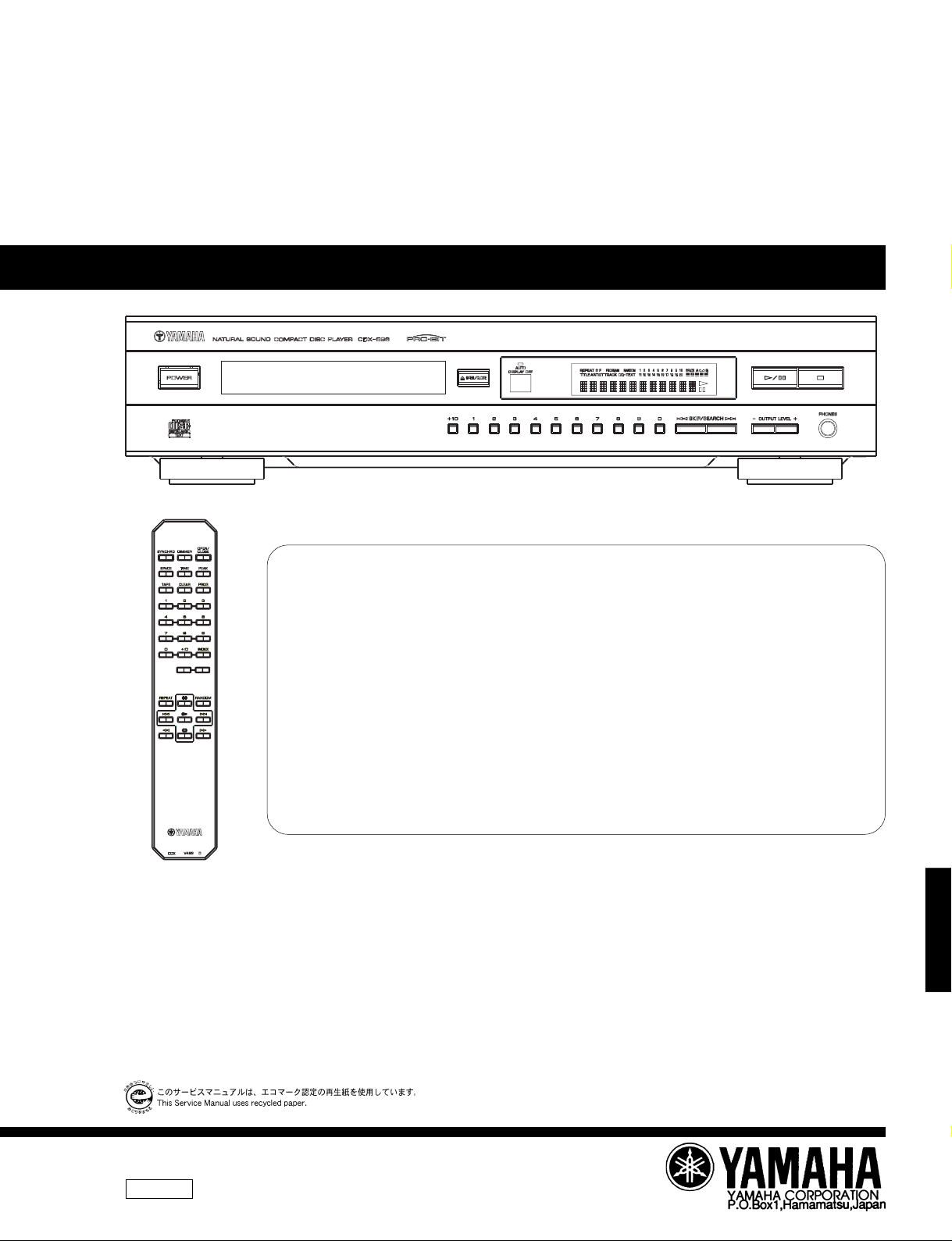
CDX-596
COMPACT DISC PLAYER
CDX-596
SERVICE MANUALSERVICE MANUAL
SERV ICE M A N UAL
TEXT/
This manual has been provided for the use of authorized YAMAHA Retailers and their service personnel.
It has been assumed that basic service procedures inherant to the industry, and more specifically YAMAHA Products, are already
known and understood by the users, and have therefore not been restated.
WARNING: Failure to follow appropriate service and safety procedures when servicing this product may result in personal
OUTPUT LEVEL
+
-
IMPORTANT: The presentation or sale of this manual to any individual or firm does not constitute authorization, certification or
The data provided is believed to be accurate and applicable to the unit(s) indicated on the cover. The research, engineering, and
service departments of YAMAHA are continually striving to improve YAMAHA products. Modifications are, therefore, inevitable
and specifications are subject to change without notice or obligation to retrofit. Should any discrepancy appear to exist, please contact
the distributor's Service Division.
WARNING: Static discharges can destroy expensive components. Discharge any static electricity your body may have accumu-
IMPORTANT: Turn the unit OFF during disassembly and parts replacement. Recheck all work before you apply power to the unit.
00
4
■
CONTENTS
TO SERVICE PERSONNEL ....................................... 1-2
REAR PANELS .............................................................. 3
SPECIFICATIONS .......................................................... 4
INTERNAL VIEW ........................................................... 4
DISASSEMBLY PROCEDURES ................................ 5,6
STANDARD OPERATION CHART ............................ 6,7
TEST MODE ................................................................ 7,8
ERROR MESSAGE................................................... 9,10
DISPLAY DATA ........................................................... 11
injury, destruction of expensive components and failure of the product to perform as specified. For these reasons,
we advise all YAMAHA product owners that all service required should be performed by an authorized
YAMAHA Retailer or the appointed service representative.
recognition of any applicable technical capabilities, or establish a principle-agent relationship of any form.
lated by grounding yourself to the ground buss in the unit (heavy gauge black wires connect to this buss).
IMPORTANT NOTICE
CDX-596
IC DATA .................................................................. 12-16
BLOCK DIAGRAM ....................................................... 17
PRINTED CIRCUIT BOARD ................................... 18-21
IC BLOCK .................................................................... 22
WAVEFORMS .............................................................. 23
SCHEMATIC DIAGRAM .............................................. 24
PARTS LIST ............................................................ 25-33
REMOTE CONTROL TRANSMITTER......................... 34
100708
Page 2
CDX-596
■
TO SERVICE PERSONNEL
1. Critical Components Information.
Components having special characteristics are marked
and must be replaced with parts having specifications equal
to those originally installed.
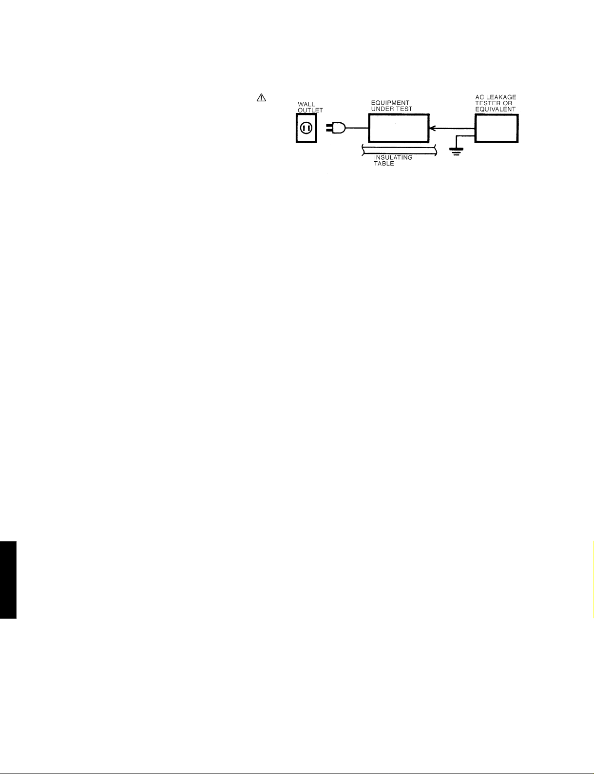
● Meter impedance should be equivalent to 1500 ohm shunted
by 0.15µF.
● Leakage current must not exceed 0.5mA.
● Be sure to test for leakage with the AC plug in both
polarities.
CAUTION: USE OF CONTROLS OR ADJUSTMENTS OR PERFORMANCE OF PROCEDURES OTHER THAN THOSE
CAUTION: USE OF CONTROLS OR ADJUSTMENTS OR PERFORMANCE OF PROCEDURES OTHER THAN THOSE
SPECIFIED HEREIN MAY RESULT IN HAZARDOUS RADIATION EXPOSURE.
SPECIFIED HEREIN MAY RESULT IN HAZARDOUS RADIATION EXPOSURE.
THE COMPACT DISC PLAYER SHOULD NOT BE ADJUSTED OR REPAIRED BY ANYONE EXCEPT PROPERLY
QUALIFIED SERVICE PERSONNEL.
PROTECTION OF EYES FROM LASER BEAM DURING SERVICING
This set employs a laser. Therefore, be sure to carefully
follow the instructions below when servicing .
1. Laser Diode Properties
WARNING: CHEMICAL CONTENT NOTICE!
The solder used in the production of this product contains LEAD. In addition, other electrical/electronic
and/or plastic (where applicable) components may also contain traces of chemicals found by the
California Health and Welfare Agency (and possibly other entities) to cause cancer and/or birth defects
or other reproductive harm.
DO NOT PLACE SOLDER, ELECTRICAL/ELECTRONIC OR PLASTIC COMPONENTS IN YOUR MOUTH
CDX-596
FOR ANY REASON WHATSOEVER!
Avoid prolonged, unprotected contact between solder and your skin! When soldering, do not inhale
solder fumes or expose eyes to solder/flux vapor!
● Material : GaAlAs
● Wavelength : 780 nm
● Emission Duration : Continuous
● Laser Output : max. 44.6 µW*
* This output is the value measured at a distance of
about 200 mm from the objective lens surface on
the Optical Pick-up Block.
2. When checking the laser diode emission, keep your
eyes more than 30 cm away from the objective lens.
If you come in contact with solder or components located inside the enclosure of this product, wash your
hands before handling food.
1
Page 3
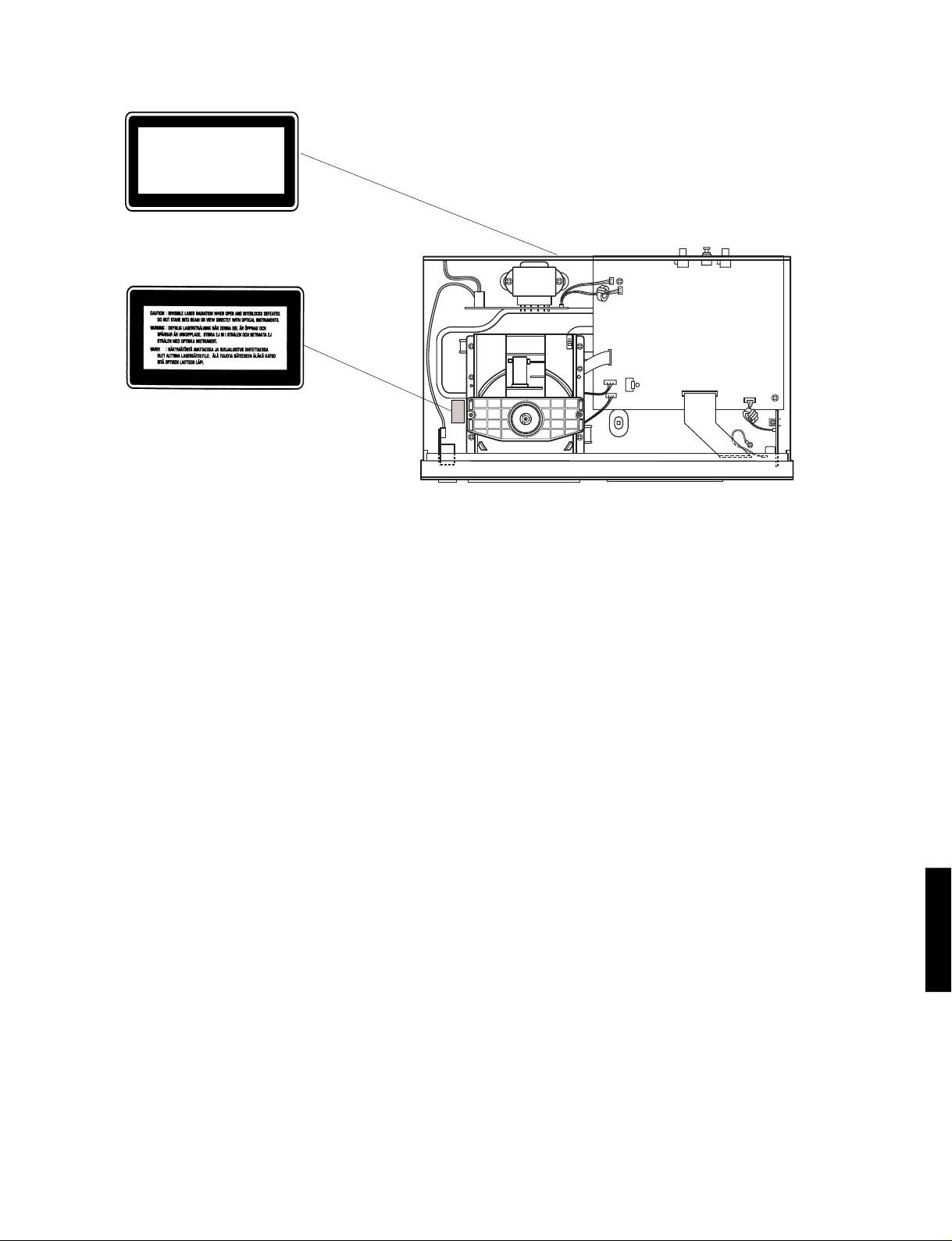
➀ G, B models
CLASS 1 LASER PRODUCT
➁ G, B models
CDX-596
English
➀
THIS PRINTING (SEE POSITION SHOWN IN THE ILLUSTRATION) INFORMS THE USER THAT THE APPARATUS
CONTAINS A LASER COMPONENT.
➁ THIS LABEL (SEE POSITION SHOWN IN THE ILLUSTRATION) WARNS THAT ANY FURTHER PROCEDURE WILL
BRING THE USER INTO EXPOSURE WITH THE LASER BEAM.
CAUTION : USE OF CONTROLS, ADJUSTMENTS OR PERFORMANCE OF PROCEDURES OTHER THAN THOSE
SPECIFIED HEREIN, MAY RESULT IN HAZARDOUS RADIATION EXPOSURE.
Swedish
➀
DENNA MÄRKNING (SE FIGUR) UPPLYSER OM ATT DET I APPARATEN INGÅR EN LASERKOMPONENT AV TYP
KLASS 1.
➁ VARNINGSMÄRKNING (SE FIGUR) FÖR STRÅLNING. INGREPP I APPARATEN BÖR ENDAST FÖRETAGAS AV
FACKMAN MED KÅNNEDOM OM LASER. APPARATEN INNEHÄLLER EN LASERKOMPONENT SOM AVGER
STRÅLNING ÖVERSTIGANDE GRÄNSEN FÖR LASERKLASS 1.
VARNING : OSYNLIG LASERSTRÅLNING NÄR DENNA DEL ÄR ÖPPNAD: BETRAKTA EJ STRÅLEN.
Danish
➀
DETTE MÆRKAT ER ANBRAGT SOM VIST I ILLUSTRATIONEN FOR AT ADVARE BRUGEREN OM AT APPARATET
INDEHOLDER EN LASERKOMPONENT.
➁ DETTE MÆRKAT OM LASEREN ER ANBRAGT PÅ APPARATET SOM EN OPLYSNING OM AT APPARATET
INDEHOLDER ET LASERKOMPONENT.
ADVARSEL : INDGREB BOR KUN FORETAGES AF EN FAGMAND DA DER ER RISIKO FOR RADIOAKTIV
STRÅLING.
ADVARSEL : USYNLIG LASERSTRÅLING VED ÅBNING.
UNDGÅ UDSAETTELSE FOR STRÅLING.
CDX-596
Finnish
VARO! :
AVATTAESSA OLET ALTTIINA NÄKYMÄTTÖMÄLLE LASERSÄTEILYLLE. ÄLÄ KATSO SÄTEESEEN.
2
Page 4
CDX-596
■
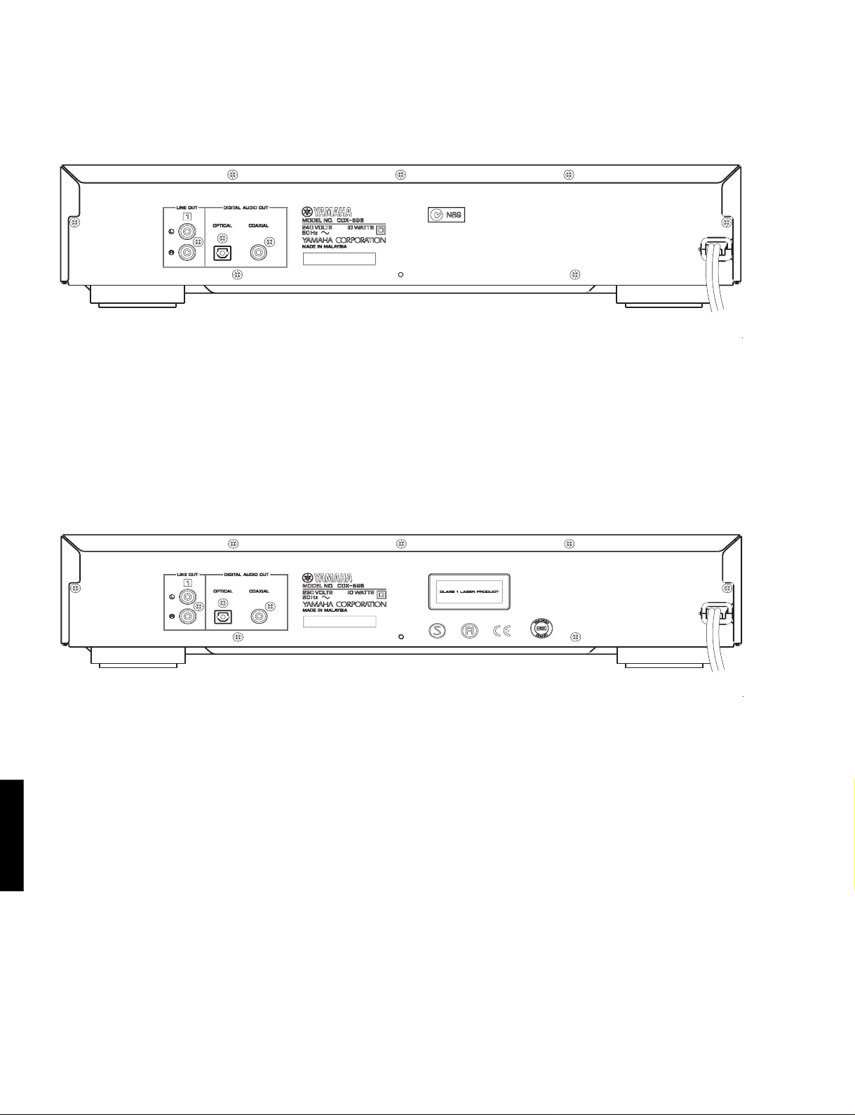
REAR PANELS
A model
G, B models
CDX-596
3
Page 5
■
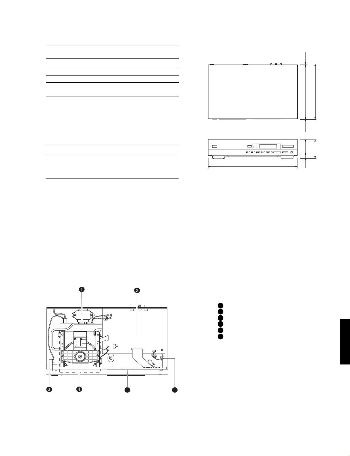
435(17-1/8")
16
(5/8")
96
(3-3/4")
5.5
(3/16")
261.5
(10-5/16")
6
(1/4")
277
(10-7/8")
80
(3-1/18")
SPECIFICATIONS
CDX-596
Output Level
1kHz, 0dB 2.0 ± 0.5Vrms
Signal to Noise Ratio (EIAJ) 115dB
Dynamic Range 100dB
Harmonic Distortion+Noise (1kHz) 0.0025%
Frequency Response
2Hz — 20kHz ±0.5dB
Power Requirements
B, G models 230V AC 50Hz
A model 240V AC 50Hz
Power Consumption 10W
Dimensions (W x H x D) 435 x 96 x 277mm
(17-1/8" x 3-3/4" x 10-7/8")
Weight 3.7kg (7 lbs 11 oz)
Finish
CDX-596BL Black color
CDX-596GD Gold color
CDX-596TI Titanium color
Accessories Pin plug cord
Remote control transmitter
(Dry-cell : x 2: Size “AA”, R06)
*Specifications are subject to change without notice.
● DIMENSION
Unit : mm (inch)
A .............. Australian model
B .................... British model
G ............... European model
■
INTERNAL VIEW
1 MAIN P.C.B. (3)
2 MAIN P.C.B. (1)
3 MAIN P.C.B. (4)
4 CD MECHANISM UNIT
5 MAIN P.C.B. (2)
CDX-596
6 MAIN P.C.B. (5)
5
6
4
Page 6
CDX-596
■
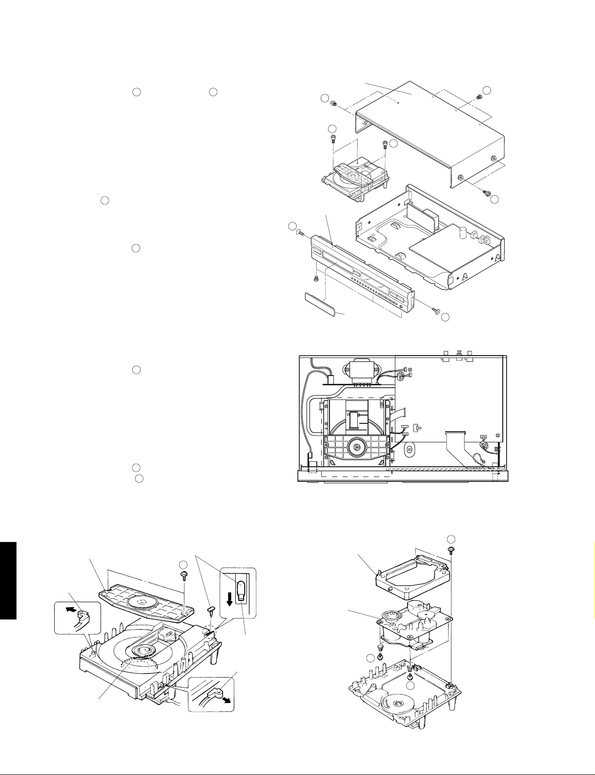
DISASSEMBLY PROCEDURES
(Remove parts in disassembly order as numbered.)
1. Removal of Top Cover
a. Remove 4 screws ( ) and 3 screws
1 2
( )
in Fig. 1.
b. Lift the Top Cover at the rear and move it rear-ward.
2. Removal of Front Panel
a. Press the OPEN/CLOSE key and open the tray.
Then remove the Lid attached to the front edge of the
tray in Fig. 2.
Press the OPEN/CLOSE key and close the tray, then
unplug the power cord.
b. Remove 3 connectors (CB100, CB202, CB301) in Fig.
2.
c. Remove 5 ( ) screws in Fig. 1.
d.
Remove 2 hooks and then pull the Front Panel forward.
3
3. Removal of CD Mechanism Unit
a. Remove 3 connectors (CB1, CB2, CB3) in Fig. 2.
b. Remove 4 screws ( ) in Fig. 1.
4
4. Removal of Tray Unit
a. Remove 2 screws ( ) and then remove the Chuck-
5
ing Unit in Fig. 3.
b. Remove 1 hook and then remove the Stopper Pin in
Fig. 3.
c. Rotate the Drive Gear and then open the Tray Unit in
Fig. 3.
d. Detach the Stoppers on both sides and then pull out
the Tray in Fig. 3.
5. Removal of Pick-up Head
a. Remove 2 screws ( ) in Fig. 4.
b. Remove 4 screws ( ) and then remove the Drive
6
7
Unit in Fig. 4.
c. Remove the gear A in Fig. 5.
d. Pull out the Sled Shaft in Fig. 5.
e. Remove the Pick-up Head.
Front Panel
3
Top Cover
1
4
CB203
CB202
Lid
4
CD Mechanism
Unit
CB201
W201
CB200
W202
CB1
CB2
CB3
PJ101
3
CB101
CB301
2
1
Fig. 1
PJ100
CB100
Fig. 2
CDX-596
5
Chucking Unit
Stopper
Drive Gear
Stopper Pin
5
Sub Chassis (S)
6
Drive Unit
Hook
7
Stopper
7
Fig. 3 Fig. 4
Page 7
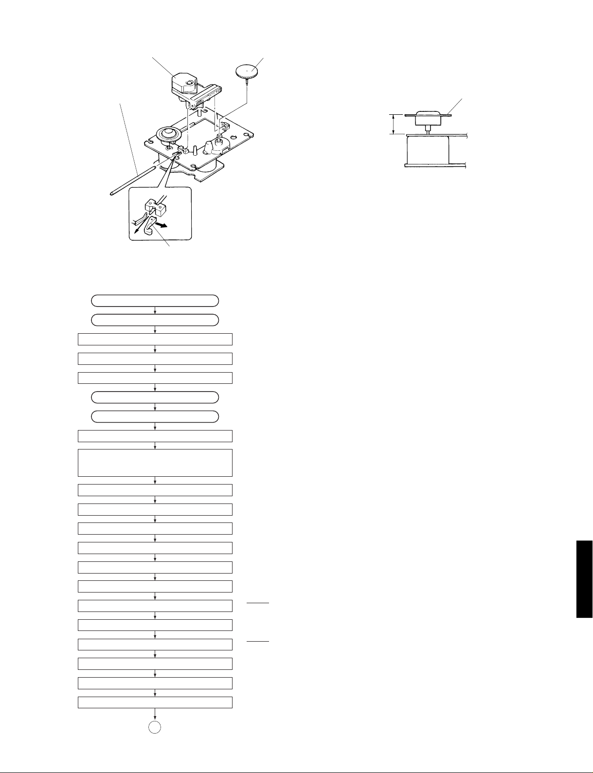
Pick-up Head Gear A
CDX-596
Check that the disc table height is as specified below.
Sled Shaft
Stopper
■
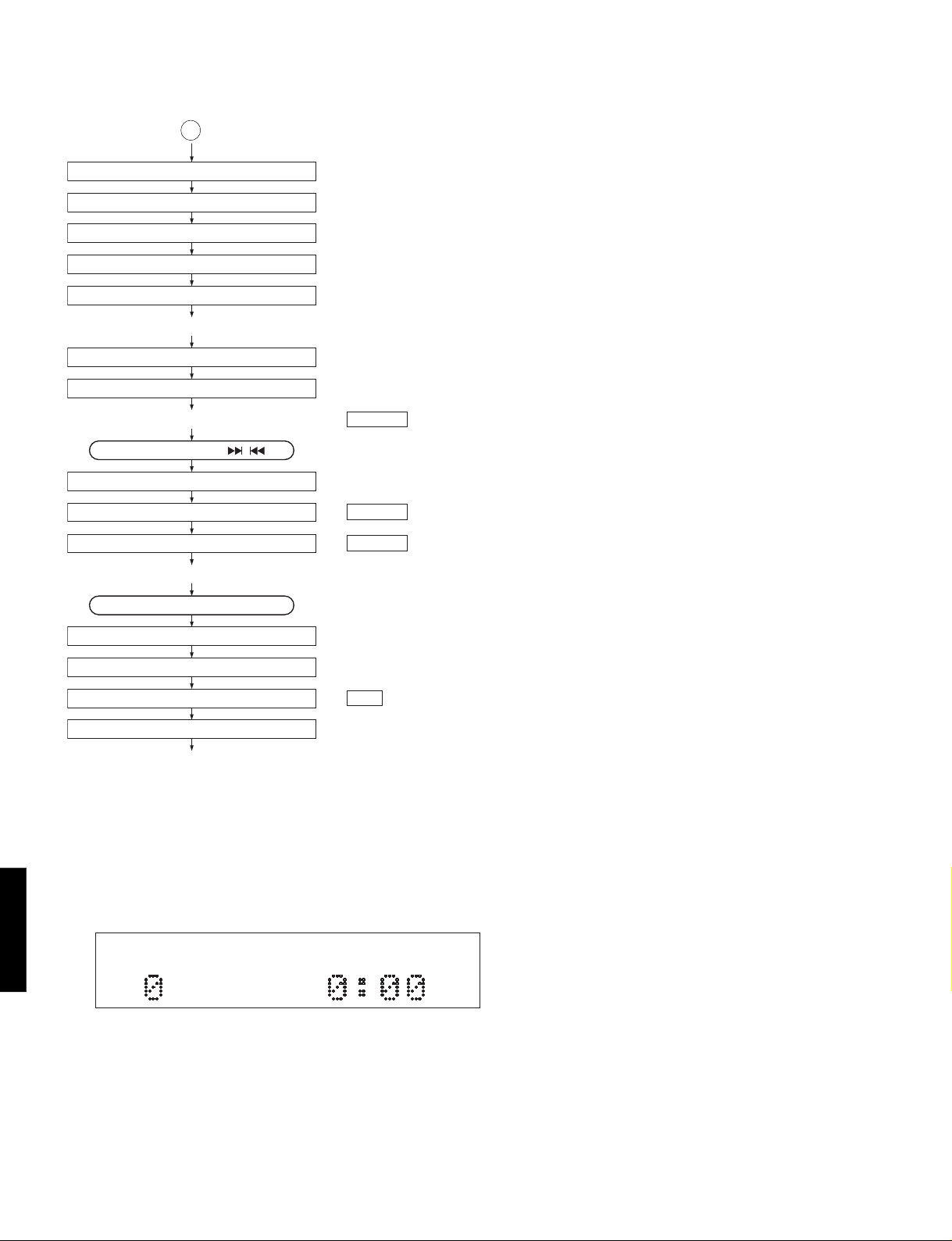
STANDARD OPERATION CHART
POWER ON If a disc is not loaded, "0:00" appears in the time indicator.
Press OPEN/CLOSE key.
Forced feed return operation
Clamp down operation
"OPEN" appears in the TIME indicator.
“TRV” signal is output until detection of LIMIT switch.
Disc Table
19.4 ± 0.2mm
Fig. 5
Tray open
Load a disc.
Press PLAY key or push the tray.
Tray closed
Disc mechanism unit clamped up.
Feed inward switch reached.
Tracking offset auto ADJ
Laser ON
Focus offset auto ADJ
Disc scan
Focus gain rough ADJ
Focus search operation
Focus lock servo ON
Spindle motor accelerated.
Tracking servo ON
Stop after detection of LOADING switch.
Proceeds to next step after detection of LOADING switch.
If FLSW = L (IC300, 21 pin)
Proceeds To Next Step.
LDON = H (IC1, 5 pin)
FLOCK = H → L (IC300, 8 pin)
TLOCK = H → L (IC300, 7 pin)
CDX-596
Spindle servo ON
VCO lock
Feed servo ON
A
6
Page 8
CDX-596
A
Tracking gain rough ADJ
Tracking balance ADJ (only tray OPEN/CLOSE)
Focus balance ADJ
Focus gain ADJ
Tracking gain ADJ
* TOC READ
After searching the beginning, PLAY starts.
After searching the beginning, MUTE is cancelled.
- * Data f etch cycle -
TRACK NO. “1” is searched.
- PLAY -
Set to SEARCH by means of , key.
TRACK search
MUTE ON
- PLAY -
Press the STOP key.
MUTE ON
Spindle motor stop
Laser OFF
Forced feed return
- STOP -
: MUTE OFF = H → L (Q201 Collector)
"0:00" appears in the time indicator.
: MUTE ON = L → H
: MUTE OFF = H → L
"0:00" appears in the time indicator.
: LDON = “H” → “L” (IC1, 5 pin)
■
(1) Turning ON the POWER while pressing the keys “PLAY/PAUSE” and “STOP” will set to the TEST mode.
CDX-596
7
TEST MODE
(When the TEST mode is set, all indicators light for 1 second.)
Page 9
CDX-596
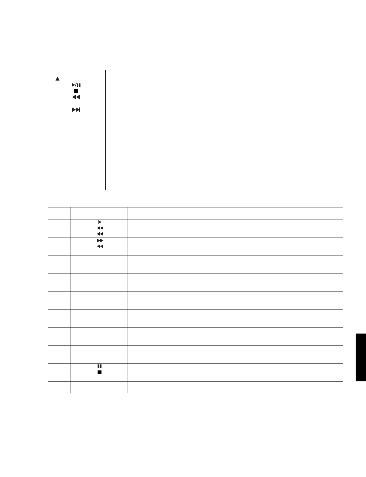
(2) Shown below are the panel key and remote control transmitter functions in the TEST mode.
● Function List of Panel keys Note) "Traverse servo" means the same as "feed servo".
PANEL KEY
OPEN/CLOSE
(SKIP/SEARCH)
(SKIP/SEARCH)
+10
1
2
3
4
5
6
7
8
9
0
Tray open/close.
FOON, TRON, SPON, TVON(FEON).
All stop. (Focus, spindle, feed, laser, tray, etc.) Initializes FL display
Inner circumference traverse servo.
Outer circumference traverse servo.
Rotating the mode of coefficients. (Coefficient mode −−− Coefficient setting −−− product mode)
Pressing twice will set to the product mode.
Returns to product mode.
Auto adjustment mode 1 (TR-off set, FO-off set, FO-rough gain adjustment)
Auto adjustment mode 2 (TR-balance, TR-rough gain adjustment)
Auto adjustment mode 3 (FO-fine gain, TR-fine gain, FO-balance adjustment)
1 TRACK KICK (–) continuously (Coefficient set up mode : address down)
1 TRACK KICK (+) continuously (Coefficient set up mode : address up)
30 TRACK KICK (–) continuously (Coefficient set up mode : upper digit down)
30 TRACK KICK (+) continuously (Coefficient set up mode : upper digit up)
150 TRACK KICK (–) continuously (Coefficient set up mode : lower digit down)
150 TRACK KICK (+) continuously (Coefficient set up mode : lower digit up)
FUNCTION
● Function List of Remote Control Transmitter
CODE
01
02
04
05
06
07
08
0A
0B
0C
0D
0F
10
11
12
13
14
15
16
17
18
19
1A
1B
1E
55
56
57
58
5D
KEY
OPEN/CLOSE
REPEAT S/F
TIME
INDEX
PROG
CLEAR
SPACE
0
1
2
3
4
5
6
7
8
9
+10
RANDOM
DIMMER
TAPE
SYNCHRO
PEAK
Tray open/close.
PLAY (FOON, TRON, TVON(FEON), SPON)
Inner circumference traverse servo.
Inner 10 tracks kick continuously.
Outer 10 tracks kick continuously.
Outer circumference traverse servo.
FOON, TROF (Enter focus search if focus servo is off.)
Checks FL display. (88 8888 --- goes out −−− All lamps.)
FOON, TROF, TVOF(FEOF) (Enter focus search if focus servo is off.)
Rotates or accelerates spindle.
Decelerates spindle. (checking EFM pattern and reflected STAT)
FOOF, TROF, TVOF(EFOF)
150 TRACK KICK (+) continuously (Coefficient set up mode : lower digit up)
Returns to product mode. (tray inoperative.)
Auto adjustment mode 1 (TR-off set, FO-off set, FO-rough gain adjustment)
Auto adjustment mode 2 (TR-balance, TR-rough gain adjustment)
Auto adjustment mode 3 (FO-fine gain, TR-fine gain, FO-balance adjustment)
1 TRACK KICK (–) continuously (Coefficient set up mode : address down)
1 TRACK KICK (+) continuously (Coefficient set up mode : address up)
30 TRACK KICK (–) continuously (Coefficient set up mode : upper digit down)
30 TRACK KICK (+) continuously (Coefficient set up mode : upper digit up)
150 TRACK KICK (–) continuously (Coefficient set up mode : lower digit down)
Rotating the mode of coefficients.
SPON (Spindle servo on.)
Checks FL display. (All lamps −−− 88 8888 −−− goes out.)
FOON, TROF, TVOF(EFOF) (Enter focus search if focus servo is off.)
All stop. (Focus, spindle, traverse, laser, tray, etc.)
Spindle free (off)
TV(Feed) REV
-
CUSTOM CODE = (79)x
FUNCTION
CDX-596
8
Page 10
CDX-596
■
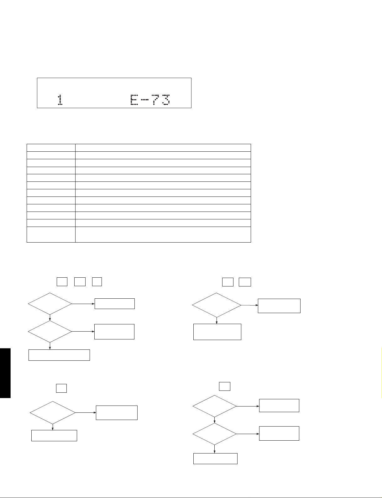
ERROR MESSAGE
(1) When operation is terminated in an abnormal condition (stop or open), pressing STOP on the remote control while
pressing STOP on the panel will set to the error message display enable mode.
(2) Shown below is an example of display. ("E-73" as an example)
(3) This function stays effective till the power is turned OFF. (It is cleared at OFF.)
(4) Listed in the table below are error messages.
● Error Messages List
ERROR MESSAGES
E – X0
E – X1
E – 71
E – 72
E – 73
E – 94
E – A5
E – X7
E – X8
Er r
Data cannot be read after finishing search.
Data cannot be read during PLAY(X=0), PAUSE(X=3), or SCAN(X=2).
At the start, tracking servo is not effective.
At the start, spindle servo PLL is not effective.
At the start, data cannot be read.
Close switch does not work with tray closed.
Open switch does not work with tray open.
Traverse(Feed) inner switch does not work.
Recovery action fails after focus drop.
MN35511AL does not give response of SENSE, with resetting by the
DESCRIPTION
unit’s microcomputer.
1) Error Code Troubleshooting
Error code X0 , X1 , 73 ...... Data cannot be read.
Is disc dirty or
scratched?
NO
Pick-up position
Within disc range
Pick-up defective, Spindle system
defective (Motor fails to run, etc.).
YES
Outermost
(on mirror
surface)
Check by using
another disc.
TRACKING
servo defective.
FEED servo defective.
*No. for each state
(meaning of "X")
PLAY X="0"
SCAN X="2"
PAUSE X="3"
PEAK SEARCH X="4"
SEARCH X="5"
START X="7"
STOP X="8"
LOADING X="9"
OPEN X="–"
NO DISC X="C"
Error codes 94 , A5 ..... Poor tray loading operation.
Does tray
operate when
OPEN/CLOSE key is
pressed?
NO
Motor defective.
Control IC (IC2) defective.
Microcomputer defective.
Loading switch defective.
YES
Poor Microcomputer
defective.
CDX-596
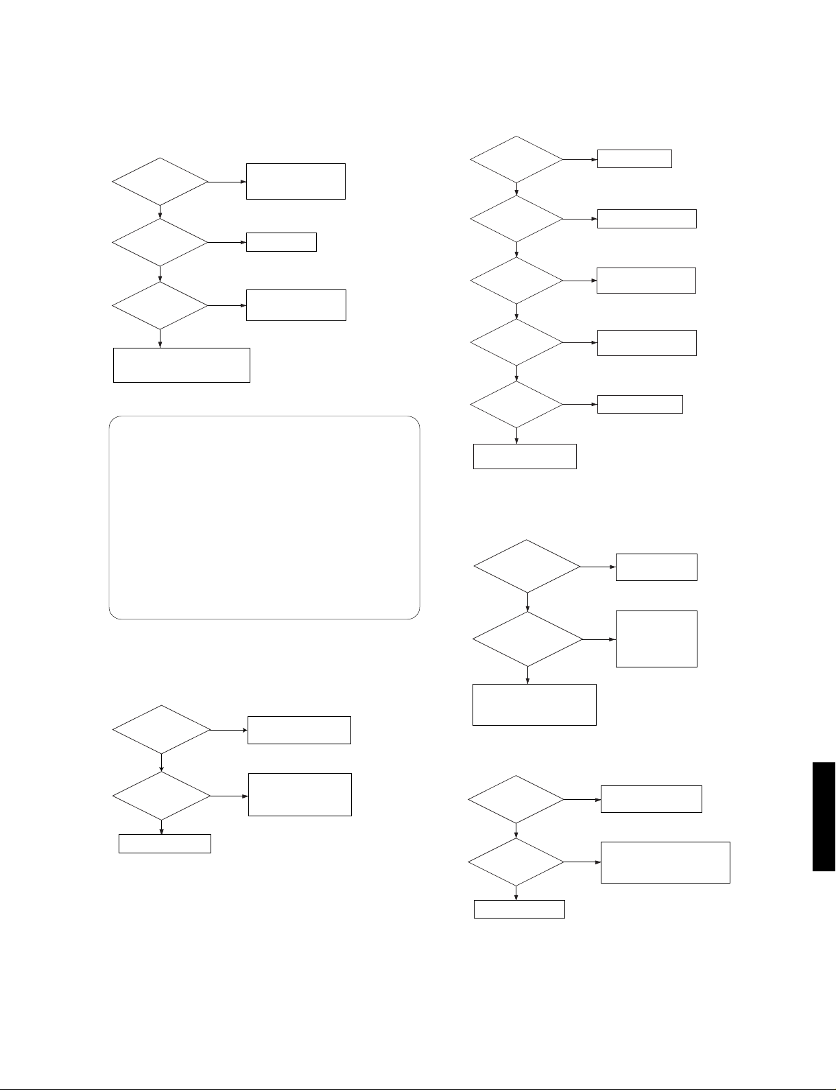
Error code X7 ............. FEED operation defective.
9
Is forced
feed operation
available in TEST
mode?
NO
FEED servo defective.
Microcomputer defective.
YES
Y...Outward
T...Inward
(Limit switch fails)
Feed limit switch
defective.
Microcomputer defective.
Error code X8 ............ Focus drops.
Is disc dirty or
scratched?
NO
Pick-up position
Within disc range
FOCUS servo defective.
Pick-up defective.
YES
Outermost
(on mirror
surface)
Check by using
another disc.
TRACKING servo
defective.
FEED servo defective.
Page 11
CDX-596
2) Troubleshooting from System Malfunctions
a) Tray fails to come out/go in.
Tray starts to
move but stops.
NO
Is output
available at LOADING
terminal?
NO
FLSW = "L"
NO
Limit switch defective.
FEED servo system defective.
Microcomputer, IC1 or IC3 defective.
YES
YES
YES
Poor mechanism
operation.
Wire caught.
Loose gear, etc.
Motor defective.
Microcomputer or
LOADING IC (IC2)
defective.
When tray fails to close completely
(when it stops midway)
[Corrective measure]
1) Turn ON the power and open the tray.
* If it failed to open (head and tray contacting each other),
open it after removing the chucking unit.
2) Turn OFF the power and force the tray to go in fully and
close.
3) With the power turned ON, open and close the tray to
check if the tray close completely.
b) No sound generated, Sound cut during play.
( but time display advances properly)
YES
MUTING applied.
NO
Is normal
digital data input to
DAC IC(IC101)?
NO
NO
IC3 or IC100 defective.
MUTING circuit defective.
Microcomputer defective.
DAC IC(IC101) defective.
YES
Audio amplifier
(IC102,103) defeective.
c) Operates as if no disc loaded. (although loaded)
Does tray
load properly?
YES
Is pick-up at
innermost position?
YES
Is FOCUS
lock done?
YES
Does spindle
motor run?
YES
Is EFMI signal
normal?
YES
IC3 defective.
Microcomputer defective.
NO
Poor tray loading.
NO
Feed limit switch defective.
NO
NO
NO
FOCUS servo
system defective.
Spindle servo
system defective.
Jitter defective.
d) Sound skips.
(Time display fails to advance properly)
Is disc dirty,
scratched or
warped?
NO
Is disc or disc
stabilizer in contact with
mechanism?
NO
Tracking servo system defective.
FEED servo system defective.
FOCUS servo system defective.
Pick-up defective.
YES
YES
Check by using a
known good disc.
Poor mechanism
accuracy.
Floating rubber/
spring deformed.
Pick-up connector
assembly caught.
e) No search provided. (Sound skipped after search)
Is disc dirty,
scratched or
warped?
NO
Is TER
waveform normal?
NO
IC3 defective.
YES
YES
Check by using a
known good disc.
Tracking servo system defective.
FEED servo system defective.
FOCUS servo system defective.
Pick-up defective.
CDX-596
10
Page 12

CDX-596
■
DISPLAY DATA
V300 : 14-BT-56GN
&0
#6
PATTERN AREA
q
● PIN CONNECTION
Pin No. 1 2 3456789101112131415161718192021222324252627282930
Connection F1 F1 NP 14G 13G 12G 11G 10G 9G 8G 7G 6G 5G 4G 3G 2G NX NX NX NX 1G IC P35 P34 P33 P32 P31 P30 P29 P28
Pin No. 31 32 33 34 35 36 37 38 39 40 41 42 43 44 45 46 47 48 49 50 51 52 53 54 55 56 57 58 59 60
Connection P27 P26 NP F2 F2 F2 F2 NP P25 P24 P23 P22 P21 P20 P19 P18 P17 P16 P15 P14 P13 NX NX NX NX P12 P11 P10 P9 P8
Pin No. 61 62 63 64 65 66 67 68 69 70
Connection P7 P6 P5 P4 P3 P2 P1 NP F1 F1
Note 1) F1, F2 ......... Filament
2) NP .............. No Pin
3) NX .............. No Extend pin
4) P1~P35....... Datum Line
5) 1G~14G...... Grid
6) IC ................ Internal Connection
#5
● GRID ASSIGNMENT ● ANODE CONNECTION
CDX-596
11
Page 13

■ IC DATA
IC100: YSZ914B-F
DAFC
CDX-596
VDD
VSS
SYNC/LR
BCKI
128Fs
VSS
VDD
MUTE0
SO0
OMOD1
OMOD0
GSEL1
VDD
VSS
SO1
GSEL0
MUTE1
44 43 42 41 40 39 38 37 36 35 34
1
2
3
SI1
4
SI0
5
6
7
8
9
10
11
FS1
MUTE2
FS0
SO2
IMOD2
WCKO
IMOD1
SO3
IMOD0
BCKO
VDD
VSS
4
SI0
PROBIT DELAY
BIT SHIFT
VSS
INPUT
33
RESET
32
LENG
31
PRO
30
ISM
29
KM0
28
TEST
27
KM1
26
FIX
25
VSS
24
VDD
23
MUTE3
2221201918171615141312
3
SI1
INPUT
LEVEL DET COUNTER CALCULATOR
DELAY
BIT SHIFT
LEVEL DET COUNTER CALCULATOR
VDD
OUTPUT
OUTPUT
11
14
10
15
17
19
16
23
SO0
SO1
MUTE0
MUTE1
SO2
SO3
MUTE2
MUTE3
.oNNIPEMANO/INOITCNUF.oNNIPEMANO/INOITCNUF
1DDVylppusrewoPV5+323ETUMO )etuM:H(langisetuM1hc
2SSVDNG42DDVylppusrewoPV5+
31ISI )3,2hc(NIatadlaireS52SSVDNG
40ISI )1,0hc(NIatadlaireS62XIFI FFO/NOedafssorC
5RL/CNYSI langis.cnyS721MKI lortnocesahpIKCB
6IKCBI )kcolcmetsyS(kcolctiB82TSETI )tseT:L(tseT
7SF821I langisSF821920MKI lortnoc.cnysemarF
8SSVDNG03MSII enilNInarofhcforebmuN
9DDVylppusrewoPV5+13ORPI lortnoctib-orP
010ETUMO )etuM:H(langisetuM0hc23GNELI tib-orpfohtgneldrowtupnI
110OSO TUOatadlaireS0hc33TESERIteseR
21DDVylppusrewoPV5+43SSVDNG
31SSVDNG53DDVylppusrewoPV5+
411OSO TUOatadlaireS1hc630DOMII
612ETUMO )etuM:H(langisetuM2hc832DOMII
712OSO TUOatadlaireS2hc930SFI
81OKCWO kcolcdrowlaireS041SFI
913OSO TUOatadlaireS3hc140LESGI
02OKCBO kcolctiblaireS241LESGI
12SSVDNG340DOMOI
22DDVylppusrewoPV5+441DOMOI
CDX-596
tamrofenilNI511ETUMO )etuM:H(langisetuM1hc731DOMII
lortnocetargnilpmaS
lortnocniaggnitaolF
tamrofenilTUO
12
Page 14

CDX-596
IC3 : MN35511AL
Signal Process Controller (SPC) & D/A Converter
VDDX2X1
VSS
XSEL
CRC
60 59 58 57 56 55 54 53 52 51 50 49 48 47 46 45 44 43 42 41
FLAG
PCK/RESY
EFM
AVSS2
AVDD2
VCOF
PLLF
DSLF
DRF
IREF
ARF
WVEL
PLAY/TRVSTOP
TOFS
DVDD1
RFFNV
TRCRS
CDX-596
/RFDET
VDD
VSS
DVSS1
/RST
/TEST
VDET
BDO
OPT
CLVS/FLAG6
DEMPO
SUBC
SBCK2
40
39
38
37
36
35
34
33
32
31
30
29
28
27
26
25
24
23
22
21
SBCK
CLDCK
LDON
BDO
/RFDET
TRCRS
OFT
VDET
RFENV
TE
FE
TBAL
FBAL
VREF
FOD
TRD
KICK
ECS
ECM
PC
TVD
TRV
CRC
BLKCK
IOSEL
LRCKI
SDATI
BCKI
DIGITAL DE-EMPHASIS
8 TIMES
OVER SAMPLING
DIGITAL FILTER
PLL VCO2
DO
DAC
PEM
(L)
DEMP1/TEST2
PEM
(R)
61
VSOF2
61
VCOF2
62
AVSS1
63
OUT1C
64
OUT1D
65
OUT2D
66
OUT2C
67
AVDD1
68
DEMP0
69
CK384
70
IOSEL
71
/TEST
72
SBCK2
73
SUBC
74
SBCK
75
/CLDCK
76
IPFLAG
SDATI
LRCKI
BCKI
77
78
79
80
1 2 2 4 5 6 7 8 9 101112131415 1617181920
TX
BCLK
LRCK
SRDATA
DVSS1
DVDD1
MCLK
MDATA
MLD
SENSE
/FLOCK
BLKCK
/TLOCK
SQCK
SUBQ
STAT
DMUTE
/RST
DEMP1/TEST2
SMCK/FCLK
STATX1X2
60
57
4
5
18
71
32
FE
33
TE
34
37
35
39
17 58 59 56 19 49 69 8 7 9 44 46 45 47 48 52 53 67 62 15 14 20 68 73 72 74 75 13 55 70 78 80 79 77
A/D CONVERTER
INPUT PORT
XSEL
TIMING
GENERATOR
PITCH CONTROL
MICRO COMPUTER
SERVO
OUTPUT
38
36
PORT
SERVO
SMCK/FCLK
INTERFACE
CPU
D/A
CONVERTER
VCO
VCOF
CK384
MDATA
MCLK
MLD
ARF
DRF
IREF
DSLF
PLLF
EFM
DSL.PLL VCO
EFM DEMODULATION
SYNC INTERPOLATION
SUBCODE DEMODULATION
CIRC ERROR CORRECTION
DEINTERLEAVE
INTERPOLATION
SOFT MUTING
DIGITAL
ATTENUATION
PEAK DETECT
AUTO CUE
PCK/RESY
AVSS
AVDD
SUBCODE
BUFFER
CLV
SERVO
SUBQ
SQCK
SRAM
INTERFACE
CLVS/FLAG6
16K
DIGITAL
AUDIO
TIMING GENERATOR
13
10 43 41 40 11 12 30 31 28 27 22 25 42 29 26 21 16 1 3
WVEL
SENSE
TOFS
LDON
/FLOCK
FBAL
/TLOCK
TBAL
FOD
TRD
TVD
ECS
KICK
VREF
TRV
BCLK
DMUTE
PLAY/TRVSTOP
23 24 6 76 54 51 63 64 66 65 50
2
PC
LRCK
SRDATA
ECM
TX
FLAG
IPFLAG
AVSS2
OUT1C
OUT1D
OUT2C
AVDO2
OUT2D
Page 15

.oNNIPEMANO/INOITCNUF.oNNIPEMANO/INOITCNUF
1KLCBCN14SFOTCN
2KCRLCN24YALPCN
3RDRSCN34LEVWCN
41DDVD
51SSVDDNG54FERII tnerrucecnerefeR
6XTO langisecafretnioidualatigiD64FERDILSDrofsaiB
7KLCMIkcolcUPC74FLSDO/ILSDrofretlifpooL
8ATADMIatadUPC84FLLPO/ILLProfretlifpooL
9DLMI langisdaolUPC94FOCV
01ESNESOlangisesneS052DDVA
11KCOLF/O langiswardovressucoF152SSVADNG
21KCOLT/O langiswardovresgnikcarT25MFECN
31KCKLBO kcolckcolbedoc-buS35KCPCN
41KCQSI kcolcQedoc-buS45GALFCN
51QBUSO langisedocQedoc-buS55CRCCN
61ETUMDIlangisetuM65LESXDNG
71TATSOlangissutatS75SSVDNG
81TSR/IlangisteseR851XI noitallicolatsyrC
91KLCF/KCMSCN952XO noitallicolatsyrC
026GALF/SVLCCN06DDV
12VRTO langisdeefdecrofesrevarT162FOCVDNG
22DVTO langisevirdesrevarT261SSVADNG
32CPCN36C1TUOO langisC1MEP
42MCEO langisevirddecrofeldnipS46D1TUOO langisD1MEP
52SCEO langisevirdeldnipS56D2TUOO langisD2MEP
62KCIKOeslupkciK66C2TUOO langisC2MEP
72DRTO langisevirdgnikcarT761DDVA
82DOFO langisevirdsucoF86OPMEDlangistcetedsisahpme-eD
92FERVO egatloVecnerefeR96483KCOCN
03LABFO langisecnalabsucoF07LESOI)H(tcelesedoM
13LABTO langisecnalabgnikcarT17TSET/)H(tesedomtseT
23EFI langisrorresucoF272KCBSCN
33ETI langisrorregnikcarT37CBUSCN
43VNEFRI langisepolevneFR47KCBSCN
53TEDVDNG57KCDLC/CN
63TFOI langiskcart-ffO67GALFPICN
73SRCRTI langisesolcgnikcarT77IPMEDDNG
83TEDFR/I tcetedlangisFR87ITADSCN
930DBI tcetedtodkcalB97IKCRLCN
04NODLO langisNOresaL08IKCBCN
+
V5
44FRAIlangisFR
+
V5
+
V5
+
V5
+
V5
CDX-596
CDX-596
14
Page 16

CDX-596
IC300 : uPD78076GF-088
System Control
P16/ANI6
P17/ANI7
SS
AV
P130/ANO0
P131/ANO1
REF1
AV
P70/SI2/R
X
D
X
D
P71/SO2/T
P72/SCK2/ASCK
V
P20/SI1
P21/SO1
P22/SCK1
P23/STB
P24/BUSY
P25/SI0/SB0
P26/SO0/SB1
P27/SCK0
P80/A0
P81/A1
SS
P00/INTP0/TI00
P01/INTP1/TI01
P02/INTP2
P03/INTP3
P04/INTP4
P05/INTP5
P06/INTP6
P10/ANI0
P11/ANI1
P12/ANI2
P13/ANI3
P14/ANI4
P15/ANI5
31 32 33 34 35 36 37 38 39 40 41 42 43 44 45 46 47 48 49 50
P83/A3
P82/A2
282930
535251
P85/A5
P84/A4
P87/A7
P86/A6
AV
AV
REF0
DD
P41/AD1
P40/AD0
P43/AD3
P42/AD2
192021222324252627
626160595857565554
P45/AD5
P44/AD4
18
63
P47/AD7
P46/AD6
RESET
151617
666564
P51/A9
P50/A8
XT1/P07
XT2
14
67
P53/A11
P52/A10
V
X1
DD
706968
P55/A13
P54/A12
X2
V
SS
P127/RTP7
V
PP
P57/A15
P56/A14
P126/RTP6
P60
P125/RTP5
P61
P124/RTP4
P62
P120/RTP0
P121/RTP1
P122/RTP2
P123/RTP3
12345678910111213
100
P96
99 98 97 96 95 94 93 92 91 90 89 88 87 86 85 84 83 82 81
P95
P94
P93
P92
P91
P90
P37
P36/BUZ
P35/PCL
P34/TI2
P33/TI1
P32/TO2
P31/TO1
P30/TO0
P103
P102
P101/TI6/TO6
P100/TI5/TO5
P67/ASTB
P63
797877767574737271
P65/WR
P64/RD
80
P66/WAIT
CDX-596
TO0/P30
TI0/INTP0/P00
TI01/INTP1/P01
TO1/P31
TI1/P33
TO2/P32
TI2/P34
TI5/TO5/P100
TI6/TO6/P101
SI0/SB0/P25
SO0/SB1/P26
SCK0/P27
SI1/P20
SO1/P21
SCK1/P22
STB/P23
BUSY/P24
SI2/RxD/P70
SO2/TxD/P71
SCK2/ASCK/P72
ANI0/P10-
ANI7/P17
AV
ANO0/P130
ANO1/P131
AV
INTP0/TI0/P00—
INTP3/CI0/P03
BUZ/P36
PCL/P35
AV
AV
AV
DD
SS
REF
SS
REF1
16-bit TIMER/
EVENT COUNTER
8-bit TIMER/
EVENT COUNTER1
8-bit TIMER/
EVENT COUNTER2
8-bit TIMER/
EVENT COUNTER5
8-bit TIMER/
EVENT COUNTER6
WATCHDOG TIMER
WATCH TIMER
SERIAL
INTERFACE0
SERIAL
INTERFACE1
SERIAL
INTERFACE2
A/D CONVERTER
D/A CONVERTER
INTERRUPT
CONTROL
BUZZER OUTPUT
CLOCK OUTPUT
CONTROL
78K/0
CPU CORE
RAM
DD
PROM
P00
PORT0
PORT1
PORT2
PORT3
PORT4
PORT5
PORT6
PORT7
PORT8
PORT9
PORT10
PORT11
PORT12
PORT13
REAL-TIME
OUTPUT PORT
EXTERNAL
ACCESS
VPPVSSV
SYSTEM
CONTROL
P01-P03
P04
P10-P17
P20-P27
P30-P37
P40-P47
P50-P57
P60-P67
P70-P74
P80, P81
P90-P97
P100-P107
P110-P117
P120-P127
P130,P131
RTP0/P120—
RTP7/P127
AD0/P40—
AD7/P47
A0/P80—
A7/P87
A8/P50—
A15/P57
RD/P64
WR/P65
WAIT/P66
ASTB/P67
RESET
X1
X2
XT1/P04
XT2
15
Page 17

CDX-596
NIP
.oN
10PTR/021PWSPOI hctiwstimilnepoyarT152A/28PKLB/O 1157CLroflangislortnoC
21PTR/12PWSLCI hctiwstimilesolcyarT253A/38POTSRCFAD
32PTR/221PCN354A/48PCN
43PTR/321PETUMO langisetumgolanA455A/58PFFODEEFO langisetumdeeF
54PTR/421PTSR/O langisteseR556A/68PCN
65PTR/521PETUMDO langisetumlatigiD657A/78PCN
76PTR/621PKCOLT/I langisovresgnikcarT750DA/04PCN
87PTR/721PKCOLF/I langisovressucoF851DA/14PCN
9V(CI
012X2XlanimretCSO063DA/34PCN
111X1XlanimretCSO164DA/44PCN
21DDVDDV
312TX2TXCN366DA/64PCN
4170P/1TX1TX
51TESERTESER/I langisteseR568A/05PCN
6100IT/0PTNI/00PMERI langisreviecerlortnocetomeR669A/15P3DKO
7110IT/1PTNI/10PKCKLBI kcolckcolbedocbuS7601A/25P2DKO
812PTNI/20PDELO langislortnocDEL8611A/35P1DKO
913PTNI/30PWSNWODCN9621A/45P0DKO
024PTNI/40PWSPUCN0731A/55PCN
125PTNI/50PWSLFI hctiwstimildeeF17V
226PTNI/60PKCOLC/IkcolC2741A/65PCN
32VA
42VA
520INA/01PCN5716P3KI
621INA/11PCN6726P2KI
722INA/21PCN7736P1KI
823INA/31PCN87DR/46P0KI
924INA/41PADSO/IMORPEErofataD97RW/56PCN
035INA/51PLCSO MORPEErofkcolC08TIAW/66PCN
136INA/61PCN18BTSA/76PCN
237INA/71PCN285OT/5IT/001PCN
33VA
430ONA/031PSLC/NPOO langisesolC/nepO48201PCN
531ONA/131PLRTCGO langislortnocniaG58301PCN
63VA
73DxR/2IS/07PQBUSI langisQedoc-buS781OT/13PCN
83DxT/2OS/17PTATSI langissutatS882OT/23PCN
93KCSA/KCS/27PKCQSO Qedoc-busrofkcolcretsigeR981IT/33PCN
04V
141IS/02PCBUSI langislairesedoc-buS19LCP/53PCN
241OS/12PCN29ZUB/63PCN
341KCS/22P2KCBSO kcolcedoc-buS3973PNATSO langisybdnatS
44BTS/32PDLMO ossecorp-µroflangisdaoLr4909P
54YSUB/42PESNESI langisesneS5919P
640BS/0IS/52POSCN6929P
741BS/0OS/62PATADMO rossecorp-µrofataD7939P
840KCS/72PKLCMO rossecorp-µrofkcolC8949P
940A/08PSC/CN9959P
051A/18PECO 11757CLroflangiselbanepihC00169P
PP
DD
0FER
SS
1FER
SS
EMAN
ECIVEDTIUCRICECIVEDTIUCRIC
)CIDNG952DA/24PCN
DDVA
SSVADNG386OT/6IT/101PCN
SSVDNG092IT/43PCN
O/INOITCNUF
+
V5
+
V5
+
V5
0FERVADNG4706P4KI
2FERV
+
V5
NIP
.oN
265DA/54PCN
467DA/74PCN
SS
3751A/75PCN
680OT/03PCN
EMAN
SSVDNG
O/INOTICNUF
3–0slangistigidyeK
4–0slangisnruterni-yeK
CDX-596
)HotdexiF(
16
Page 18

■
BLOCK DIAGRAM
CDX-596
17
Page 19

ABCDE FGHI J
1
■
PRINTED CIRCUIT BOARD
(Foil side)
FL SW
GND
FEED-
FEED+
SPDL-
SPDL+
#2 #3
CLOSE
GND
OPEN
LOADING-
LOADING+
MAIN P.C.B. (1)
To : MAIN (2)
F2
GNDCEDI
F1VP/BLKCLGND
REM+5K1K3KD3
LEDK0K2K4KD2
KD1
KDO
To : MAIN (5)
R
GND
L
2
8
OPTICAL PICK-UP
8081
KSM-213CCM
100
3
VC
VCC
E
D
A
B
C
F
GND
LD
VR
PD
FCS+
TRK+
TRK-
FCS-
36 19
4
IC1
1
18
30 15
IC2
1
14
2021
40
41
IC3
60 61
1
1
80
IC300
30 31
51
50
41
58
5
#200
AC
#201
GND
AC
AC
F2
F1
17
14
148
7
1
8
To : MAIN (3)
To : MAIN (3)
6
4
18
5
1
45
3444
1
33
IC100
11
12 22
23
1
28
IC101
14 15
4
18
5
• Semiconductor Location
Ref. No. Location
D100
D101
D200
D201
D202
D203
D204
D205
D206
D207
D209
D210
D211
D212
D213
D214
D215
D216
D217
D218
D219
D221
D222
D223
Q1
Q3
Q4
Q5
Q100
Q101
Q102
Q103
Q201
Q202
Q203
Q204
Q205
Q300
IC1
IC2
IC3
IC100
IC101
IC102
IC103
IC104
IC105
IC200
IC300
IC301
I3
H3
G5
F5
F5
F6
F5
C6
D5
D6
D5
F5
D5
D6
D6
D6
D6
D3
D6
D7
C6
F6
G4
G4
C4
E3
D2
G5
F6
H6
G6
G6
F5
E5
E6
D3
C6
F2
D4
E3
F4
H3
H4
G5
H5
H2
D6
E5
G3
G4
7
OPTICALCOAXIAL
DIGITAL AUDIO OUT
LINE OUT
1918
Page 20

ABCDE FGHI J
MAIN P.C.B. (3)
MAIN P.C.B. (2)
MAIN P.C.B. (4)
MAIN P.C.B. (5)
BE
WH
AC
IN
W200
#200
#201
WH
BE
To :
MAIN (1)
To :
MAIN (1)
To :
MAIN (1)
AC
GND
AC
AC
F2
F1
L
GND
R
PHONES
POWER
(STOP) (PLAY)
OUTPUT LEVEL
STOP/SEARCH
0987654321+10
VC
VO
G
OPEN/CLOSE
69 70
241621
32
3435
37 39 51
1
64
1617
32
33
48 49
56 6736
1
IC302
KD0
KD2K4K2K0LED
GNDCL/BLKVPF1
KD1
KD3K3K1
+5V
REMDICE
GND
F2
To : MAIN (1)
Ref. No. Location
D300
D301
D302
D303
D304
IC302
H2
D2
D2
C2
C2
F2
• Semiconductor Location
-
+
1
■
PRINTED CIRCUIT BOARD
(Foil side)
2
3
4
5
6
7
2120
Page 21

CDX-596
■
IC BLOCK
IC1 : AN8882SB
Digital Servo Head Amp
OUT
CEA
NRFDET
3T
8
7
6
ADD
Amp.
ADD
Amp.
36
A
ADD
35
Amp.
C
34
B
ADD
33
Amp.
D
32
Amp.
F
31
Amp.
E
GCA
GCA
18321
LDON
TVREF2
EQCTL
GCA
BCA
GCA
BCA
BCA
BCA
30
T
AL
TFL
FB
IC101:AD1854JRS
A/D Converter
8 x Fs
SERIAL
DATA
INTERFACE
ATTEN/
MUTE
ATTEN/
MUTE
PD/RST
INTERPOLATOR
8 x Fs
INTERPOLATOR
MUTE
L/RCLK
BCLK
SDATA
MCLK
25
26
27
2
ARF
9
RF-A GC
RFDET
AC
V
REF2
232425
FTEO
GCTRL
SERIAL CONTROL
MULTIBIT SIGNAL
DELTAMODULATOR
MULTIBIT SIGNAL
DELTAMODULATOR
CAGC
10
TEOUT
CLATCH
CCLK
INTERFACE
92324
DEEMP
RFC
17
29
TEN
CDATA
EQCTL
11
ENV DET
STANDBY
FL TCTL
28
4195
AL
CC2
TB
V
FILTER
VOLTAGE
REFERENCE
DAC
DAC
18
AVDD
IC2 : AN8785SB
PU Driver
RFOUT
12
13
BDO
OFTR
V
CC1
GND
CBDO
14
BDO
15
COFTR
16
OFTR
26
FEN
27
FEOUT
V
REF2
22
V
REF2
20
V
REF1
2
LD
1
PD
STANDBY
PVCC2
16 10 12 11 18 17 14 13 19 1
Standby
Band gap
V
CC/VREF
Reset Circuit
1.25V
-
+
IN2+
IC102, 103 : NJM5532D
Dual OP-Amp
DVDD
X2MCLK
7
CLOCK
CIRCUIT
OUTPUT
BUFFER
OUTPUT
BUFFER
ZEROR
98/48
10
1
OUT
1
17
OUTL+
OUTL-
16
12
OUTR+
13
OUTR-
228
ZEROL
–V
–IN
+IN
2
1
1
CC
–+
3
4
2814543
D4-
D2+
D2-
+-+-+-+-+-+
+
-
D3-
D4+
-
+
+
-
-
D3+
D1-
PVCC3
+-+-+-+
+
-
D5-
D1+
D5+
28 26 25 24
Thermal
Protection
Circuit
-
+
-
PVCC1
-
+
IN-
4
IN+
5
3
OUT
VREF
6
SW
PGND1
222720
IN5
SVCC
21897232
15
IN4
IN2-
CH4 SW
PGND2
IN3
IN1
IC104 : BA15218
Dual OP-Amp
–+
1
OUT1
+V
CC
8
OUT
2
7
6
5
–IN
+IN
-IN1
2
-
2
+IN1
2
GND
1
+
3
4
8
VCC
OUT2
7
6
-IN2
-
2
+
+IN2
5
IC105: HD74HC00P
2-Input NAND
1
1C
2
1A
3
1Y
4
2C
5
2A
6
2Y
7
GND
IC301 : S-24001ADP
EEPROM
6
SCL
SDA
A2
A1
A0
START/STOP
5
DEVICE ADDRESS
3
2
1
IN
D
Other ICs
IC3: See page 13.
IC100: See page 12.
IC300: See page 15.
22
DET
COMPARATOR
LOAD
IC200 : M5290P
Constant-Voltage Tracking Supply with Reset
VCC
14
V
CC
13
4C
12
4A
11
4Y
10
3C
9
3A
8
3Y
GND
ON/OFF
16 15 12 7
REFERENCE
REGULA TOR
9
ON/OFF
CONTROL
10
1
—VCC
C+
E—
14 13
3
E—
CURRENT
CONTROL
CURRENT
CURRENT
CONTROL
CONTROL
NC
PROTECTION
2
C—
OUTPUT
(+5V)
+
+
4
5
NC
OUTPUT
(—5V)
DELA Y
REFERENCE
11
IN
8
RESET OUT
DELA Y
CIRCUIT
BAL. ADJ.
6
IC302 : LC75711NE
FL Filter
V
CC
8
4
GND
SERIAL CLOCK
CONTROL
COMP
LOAD
INC
R/W
ADDRESS
COUNTER
Y–DECODER
D
OUT
HIGH VOLTAGE GENERAT OR
DATA REGISTER
E2PROM
X–DECODER
SELECTOR
DATA OUTPUT
ACK OUTPUT
CONTROL
VDD
TEST
OSCI
OSCO
CE
VSS
VFL
RES
DI
CL
64
63
62
60
57
55
61
56
59
58
SHIFT REGISTER
CONTROL
OSC DIVIDER
ADDRESS
REGISTER
BLINKCYCLE
REGISTER
DISPLAY
REGISTER
DUTYCYCLE
REGISTER
GRID
REGISTER
INSTRUCTION
DECODER
GENERATOR
GENERATOR
TIMING
GENERATOR
DC
RAM
ADDRESS
COUNTER
BLINK
DISPLAY
CONTROL
DUTY
GRID
CONTROL
CONTROL
LATCH
ROM
RAM
RAM
CG
CG
AD
LATCH
DECODER
1
AM1
2
AM2
ANODE DRIVERGRID DRIVER
35
AM35
36
AA1
37
AA2
38
AA3
39
AA4/G16
40
AA5/G15
41
AA6/G14
42
AA7/G13
43
AA8/G12
44
G11
45
G10
53
G2
54
G1
Page 22

CDX-596
■
WAVEFORMS
A B
Point (EFM : Pin10 of IC1)
V : 0.2V/div H : 0.5 µsec/div
AC range 1 : 1 probe
Point (Pin59 of IC3)
V : 1V/div H : 50 nsec/div
DC range 1 : 1 probe
0V
C D
Point (Pin10 of IC300)
V : 2V/div H : 0.2 µsec/div
DC range 1 : 1 probe
0V
Point (CH1 : Pin1 of IC200)
E
Point (CH2 : Pin8 of IC200)
V : 5V/div H : 2 sec/div
DC range1 1 : probe
0V
-10V
0V
With the POWER switch
turned ON, connect the
power cord to the AC outlet.
This waveform is not available by pushing the
power swich ON and OFF.
Disconnect the power cord
from the AC outlet.
23
Page 23

ABCDEFGH I
■
SCHEMATIC DIAGRAM
1
2
3
4
DIGITAL SERVO HEAD AMP
2.5
2.5
2.5
2.5
2.5
2.5
2.0
2.5
2.7
2.5 0.1
1.4
0
0
4.9
2.8
2.4
1.8
0
2.4
2.6
2.5
5.5
2.5
5.6
0
0
2.5
2.5
5.5
2.6
2.6
4.9
0
4.6
1.8
PU
DRIVER
2.6
2.5
2.5
0.2
3.9
3.9
2.8
2.5
2.5
2.5
2.5
5.5
2.6
2.6
2.4
2.8
~
000
2.4
2.4
5.0
0
5.0
0
2.4
2.5
0
5.0
0
1.8
0
5.0
0
4.9
0
5.0
2.4
2.5
2.5
2.5
2.5
2.5
000
0.1
2.5
2.5
2.5
2.5
2.5
2.4
2.4
2.5
2.5
2.5
2.5
2.5
0
4.9
4.8
0
~
4.9
0
0
0
0
4.9
0.1
4.8
2.5
0
4.9
~
2.4
2.4
0
4.9
4.8
0.1
0
4.9
0
0
0
2.3
2.4
4.9
4.9
0
2.5
1.3
2.5
2.5
1.8
4.9
2.2
SPC & DAC
B
0
0
0
4.9
2.6
4.9
4.9
0
0
0
3.0
3.0
A
2.52.5
2.5
0
0
2.5
0
0
0
DAFC
0
0
5.0
EEPROM
2.5
4.8
0.1
0
4.9
0.3
4.9
DAFC RST
0
4.9
4.9
4.9
4.9
0
4.9
4.9
4.9
4.9
SYSTEM
CONTROL
4.9
1.4
4.8
0.1
4.9
4.9
~
0
4.9
4.9
4.9
0
4.9
4.9
4.9
4.9
C
4.9
0
0
4.9
4.9
4.9
0
0
4.9
000
4.9
0
4.8
4.9
4.9
0
4.7
4.9
2.3
2.7
0
0
0
0
4.9
4.8
0
4.9
4.9
4.9
-0.1
5
D/A CONVERTER
1.8
2.4
4.9
2.4
2.5
0
5.0
0
0
0
0
2.6
5.0
3.3
0
5.0
0
2.3
0
2.4
2.4
0
0
0
0
0
2.3
2.4
MUTE CONTROL
3.7
4.9
4.3
5.1
4.9
4.9
4.3
3.7
5.1
4.9
4.8
5.1
5.1
-5.7
E
4.9
1.3
0
5.7
5.0
5.0
POWER
SUPPLY
-27.7
-22.2
1.2
5.7
5.7
4.9
5.7
5.5
6.2
0
POWER SUPPLY
-27.7
-28.3
5.1
5.1
0
-5.7
POWER
SUPPLY
-10.3
-5.700
-11.0
-10.3
0
9.8
5.7
9.2
0
9.8
9.8
0
-11.0
D
9.2
-29.3
-29.3
6
1.2
0
7
1.2
5
8
5.7
5.7
8
5
0
7
0
6
2
0
3
0
3
1.2
1.2
2
0
LINE AMP & LPF
9.8
0
0
0
0
0
0
9.9
-0.1
-0.1
9.9
-11.0
-0.1
-11.0
-0.1
-0.1
9.8
9.8
9.8
9.8
-0.1
-21.7
-11.0
-11.0
14
2.4
12
13
2.4
10
0
-0.1
-0.1
AC17.5
AC10.9
AC3.4
-23.8
-5.7
-5.7
4
1
0
1
0
4
-5.7
HEADPHONE
9.1
8.8
3
8
0
2
1
0
6
7
0
5
0
4
0
-9.9
-10.3
5.0
11
2.5
00
-5.6
-5.6
0
0
0
0
-5.6
-5.6
0
0
MUTING
AMP
0
PHONES
COAXIAL
OPTICAL
DIGITAL
AUDIO OUT
J
PIN CONNECTION DIAGRAM OF
TRANSISTORS, DIODES AND ICS.
2SA933S(Q,R)
B
C
E
2SA1708(S,T)
6
2SB544(E,F,G)
2SC2878(A,B)
2SD400(E,F)
E
C
B
2SB1565(E,F)
2SD2394(E,F)
IT2
HSS104
E
7
Cathade
PIC-28043TH2
1
2
3
NJM5532D
8
BA15218
S-24C01ADP
Anode
8
HD74HC00P
14
M5290P
16
AN8285SB
AD1854
28
8
1
9
1
15
1
B
C
E
C
B
AN8882SB
36
1
YSZ9148
4
1
LC75711
4
1
7
MN35511
8
uPD7076GF-XXX
14
19
18
2333
34
44
111
3348
49
64
116
4160
61
80
120
50 31
30
51
1
80
81 100
22
12
-25.2
4.9
0
4.9
0
4.9
32
17
40
21
0
4.9
0
0
0
REMOTE
SENSOR
~
~
~
~
-27.1
~
~
~
~
~
~
~
~
~
~
~~~~~~~~~~~~~~~~~~~~~~~
-27.1
-21.9
-21.9
-25.3
-25.4
-25.2
-25.2
-25.2
2.4
4.9
4.9
0.3
4.8
0.1
2.4
DISPLAY
DRIVER
~~~~~~~~~~~~~~~
-25.2
-25.2
-25.2
-25.2
-25.2
-25.2
-25.2
-25.2
-25.2
-25.4
0
0
-25.3
-27.7
-25.2
-25.2
-25.2
-25.2
-25.2
-25.2
-25.2
-25.2
-25.2
-25.2
-24.5
~
~
~
~
~
-21.9
-21.9
~
~
~~~~~~~
-25.2
-24.5
* All voltages are measured with a 10M /DC electric volt meter.
* Components having special characteristics are marked
must be replaced with parts having specifications equal to those
originally installed.
* Schematic diagram is subject to change without notice.
and
24
Page 24

■ WARNING
PA RTS LIST
■
ELECTRICAL PARTS
Components having special characteristics are marked and must be
replaced with parts having specifications equal to those originally installed.
● Carbon resistors (1/6W or 1/4W) are not included in the ELECTRICAL PARTS
List. For the part Nos. of the carbon resistors, refer to the last page.
ABBREVIATIONS IN THIS LIST ARE AS FOLLOWS :
CDX-596
C.A.EL.CHP : CHIP ALUMI. ELECTROLYTIC CAP
C.CE : CERAMIC CAP
C.CE.ARRAY : CERAMIC CAP ARRAY
C.CE.CHP : CHIP CERAMIC CAP
C.CE.ML : MULTILAYER CERAMIC CAP
C.CE.M.CHP : CHIP MULTILAYER CERAMIC CAP
C.CE.SAFTY : RECOGNIZED CERAMIC CAP
C.CE.TUBLR : CERAMIC TUBULAR CAP
C.CE.SMI : SEMI CONDUCTIVE CERAMIC CAP
C.EL : ELECTROLYTIC CAP
C.MICA : MICA CAP
C.ML.FLM : MULTILAYER FILM CAP
C.MP : METALLIZED PAPER CAP
C.MYLAR : MYLAR FILM CAP
C.MYLAR.ML : MULTILAYER MYLAR FILM CAP
C.PAPER : PAPER CAPACITOR
C.PLS : POLYSTYRENE FILM CAP
C.POL : POLYESTER FILM CAP
C.POLY : POLYETHYLENE FILM CAP
C.PP : POLYPROPYLENE FILM CAP
C.TNTL : TANTALUM CAP
C.TNTL.CHP : CHIP TANTALUM CAP
C.TRIM : TRIMMER CAP
CN : CONNECTOR
CN.BS.PIN : CONNECTOR, BASE PIN
CN.CANNON : CONNECTOR, CANNON
CN.DIN : CONNECTOR, DIN
CN.FLAT : CONNECTOR, FLAT CABLE
CN.POST : CONNECTOR, BASE POST
COIL.MX.AM : COIL, AM MIX
COIL.AT.FM : COIL, FM ANTENNA
COIL.DT.FM : COIL, FM DETECT
COIL.MX.FM : COIL, FM MIX
COIL.OUTPT : OUTPUT COIL
DIOD.ARRAY : DIODE ARRAY
DIODE.BRG : DIODE BRIDGE
DIODE.CHP : CHIP DIODE
DIODE.VAR : VARACTOR DIODE
DIOD.Z.CHP : CHIP ZENER DIODE
DIODE.ZENR : ZENER DIODE
DSCR.CE : CERAMIC DISCRIMINATOR
FER.BEAD : FERRITE BEADS
FER.CORE : FERRITE CORE
FET.CHP : CHIP FET
FL.DSPLY : FLUORESCENT DISPLAY
FLTR.CE : CERAMIC FILTER
FLTR.COMB : COMB FILTER MODULE
FLTR.LC.RF : LC FILTER ,EMI
GND.MTL : GROUND PLATE
GND.TERM : GROUND TERMINAL
HOLDER.FUS : FUSE HOLDER
IC.PRTCT : IC PROTECTOR
JUMPER.CN : JUMPER CONNECTOR
JUMPER.TST : JUMPER, TEST POINT
L.DTCT : LIGHT DETECTING MODULE
L.EMIT : LIGHT EMITTING MODULE
LED.DSPLY : LED DISPLAY
LED.INFRD : LED, INFRARED
MODUL.RF : MODULATOR, RF
PHOT.CPL : PHOTO COUPLER
PHOT.INTR : PHOTO INTERRUPTER
PHOT.RFLCT : PHOTO REFLECTOR
PIN.TEST : PIN, TEST POINT
PLST.RIVET : PLASTIC RIVET
R.ARRAY : RESISTOR ARRAY
R.CAR : CARBON RESISTOR
R.CAR.CHP : CHIP RESISTOR
R.CAR.FP : FLAME PROOF CARBON RESISTOR
R.FUS : FUSABLE RESISTOR
R.MTL.CHP : CHIP METAL FILM RESISTOR
R.MTL.FLM : METAL FILM RESISTOR
R.MTL.OXD : METAL OXIDE FILM RESISTOR
R.MTL.PLAT : METAL PLATE RESISTOR
RSNR.CE : CERAMIC RESONATOR
RSNR.CRYS : CRYSTAL RESONATOR
R.TW.CEM : TWIN CEMENT FIXED RESISTOR
R.WW : WIRE WOUND RESISTOR
SCR.BND.HD : BIND HEAD B-TITE SCREW
SCR.BW.HD : BW HEAD TAPPING SCREW
SCR.CUP : CUP TITE SCREW
SCR.TERM : SCREW TERMINAL
SCR.TR : SCREW, TRANSISTOR
SUPRT.PCB : SUPPORT, P.C.B.
SURG.PRTCT : SURGE PROTECTOR
SW.TACT : TACT SWITCH
SW.LEAF : LEAF SWITCH
SW.LEVER : LEVER SWITCH
SW.MICRO : MICRO SWITCH
SW.PUSH : PUSH SWITCH
SW.RT.ENC : ROTARY ENCODER
SW.RT.MTR : ROTARY SWITCH WITH MOTOR
SW.RT : ROTARY SWITCH
SW.SLIDE : SLIDE SWITCH
TERM.SP : SPEAKER TERMINAL
TERM.WRAP : WRAPPING TERMINAL
THRMST.CHP : CHIP THERMISTOR
TR.CHP : CHIP TRANSISTOR
TR.DGT : DIGITAL TRANSISTOR
TR.DGT.CHP : CHIP DIGITAL TRANSISTOR
TRANS : TRANSFORMER
TRANS.PULS : PULSE TRANSFORMER
TRANS.PWR : POWER TRANSFORMER ASS’y
TUNER.AM : TUNER PACK, AM
TUNER.FM : TUNER PACK, FM
TUNER.PK : FRONT-END TUNER PACK
VR : ROTARY POTENTIOMETER
VR.MTR : POTENTIOMETER WITH MOTOR
VR.SW : POTENTIOMETER WITH ROTARY SW
VR.SLIDE : SLIDE POTENTIOMETER
VR.TRIM : TRIMMER POTENTIOMETER
CDX-596
Note) Those parts marked with “#” are not included in the P.C.B. ass'y.
25
Page 25

CDX-596
Schm
Ref. PART NO. Description
* V5004600 P.C.B. MAIN(A)
* V5004700 P.C.B. MAIN(BG)
CB1 V2731000 CN.FMN 16P
CB2 VB390200 CN.BS.PIN 6P
CB3 VB390100 CN.BS.PIN 5P
CB100 VB389900 CN.BS.PIN 3P
CB101 VT707200 L.EMIT TOTX178
CB200 VL844700 CN.BS.PIN 3P
CB201 VB389900 CN.BS.PIN 3P
CB202 VP245600 CN 2P
CB203 VG879900 CN.BS.PIN 2P
* CB300 VU282100 CN 21P
* CB301 VU272100 CN 21P
C1 VJ599100 C.CE.TUBLR 0.1uF 50V
* C2 V4749000 C.EL 150uF 6.3V
C3 UA954470 C.MYLAR 0.047uF 50V
C4 UR818100 C.EL 100uF 6.3V
C5 UR818100 C.EL 100uF 6.3V
C6 UR866100 C.EL 1uF 50V
C7 VJ599100 C.CE.TUBLR 0.1uF 50V
C8 VJ599100 C.CE.TUBLR 0.1uF 50V
C9 UA953100 C.MYLAR 1000pF 50V
C10 VJ599100 C.CE.TUBLR 0.1uF 50V
C11 VF466700 C.CE.TUBLR 47pF 50V
C12 UA655100 C.MYLAR 0.1uF 50V
C13 VG278400 C.CE.TUBLR 220pF 50V
C14 UN865470 C.EL 0.47uF 50V
C15 UA655100 C.MYLAR 0.1uF 50V
C16 UA953120 C.MYLAR 1200pF 50V
C17 UA953270 C.MYLAR 2700pF 50V
C18 UN866470 C.EL 4.7uF 50V
C19 UR837470 C.EL 47uF 16V
C20 VJ599100 C.CE.TUBLR 0.1uF 50V
* C21 V4749000 C.EL 150uF 6.3V
C22 UR818100 C.EL 100uF 6.3V
C23 VF467000 C.CE.TUBLR 1000pF 50V
C24 VJ599100 C.CE.TUBLR 0.1uF 50V
C25 UR818100 C.EL 100uF 6.3V
C26 UR818100 C.EL 100uF 6.3V
C27 UR818100 C.EL 100uF 6.3V
* C28 V4749000 C.EL 150uF 6.3V
C29 UA953330 C.MYLAR 3300pF 50V
CDX-596
C30 UA655100 C.MYLAR 0.1uF 50V
C31 VG278700 C.CE.TUBLR 390pF 50V
C32 VJ599100 C.CE.TUBLR 0.1uF 50V
C33 VJ599100 C.CE.TUBLR 0.1uF 50V
C34 UA954120 C.MYLAR 0.012uF 50V
* C35 V4749000 C.EL 150uF 6.3V
C36 UA655100 C.MYLAR 0.1uF 50V
* C37 UN865220 C.EL 0.22uF 50V
C38 UA655100 C.MYLAR 0.1uF 50V
C39 VJ599100 C.CE.TUBLR 0.1uF 50V
C40 VJ599100 C.CE.TUBLR 0.1uF 50V
New Parts
*
26
Schm
Ref. PART NO. Description
* C41 V4749000 C.EL 150uF 6.3V
* C42 V4749000 C.EL 150uF 6.3V
C44 VJ599100 C.CE.TUBLR 0.1uF 50V
C45 VJ599100 C.CE.TUBLR 0.1uF 50V
C46 UR818100 C.EL 100uF 6.3V
C47 VJ599100 C.CE.TUBLR 0.1uF 50V
C60 VG279100 C.CE.TUBLR 1200pF 16V
C100 VJ599100 C.CE.TUBLR 0.1uF 50V
C101 VJ599100 C.CE.TUBLR 0.1uF 50V
C102 VJ599100 C.CE.TUBLR 0.1uF 50V
* C103 VH619100 C.EL 220uF 6.3V
C106 VJ599100 C.CE.TUBLR 0.1uF 50V
* C107 VH619100 C.EL 220uF 6.3V
C108 VJ599100 C.CE.TUBLR 0.1uF 50V
C109 VJ599100 C.CE.TUBLR 0.1uF 50V
C110 VG287200 C.EL 10uF 50V
C111 VG287200 C.EL 10uF 50V
C112 VJ599100 C.CE.TUBLR 0.1uF 50V
C113 VJ599100 C.CE.TUBLR 0.1uF 50V
C114 VJ599100 C.CE.TUBLR 0.1uF 50V
* C115 Vi715500 C.MYLAR 1000pF 50V
C116 VJ599100 C.CE.TUBLR 0.1uF 50V
* C117 VE016600 C.EL 220uF 6.3V
C118 VA761400 C.CE 47pF 50V
C119 VA761400 C.CE 47pF 50V
* C120 VQ462600 C.MYLAR 220pF 50V
* C121 Vi715500 C.MYLAR 1000pF 50V
C122 VQ572600 C.EL 1uF 100V
* C123 V2508400 C.MYLAR 1000pF 50V
* C124 VQ462600 C.MYLAR 220pF 50V
* C125 V2508400 C.MYLAR 1000pF 50V
C126 VQ572600 C.EL 1uF 100V
* C127 VQ462600 C.MYLAR 220pF 50V
* C128 VQ462600 C.MYLAR 220pF 50V
C129 VQ572600 C.EL 1uF 100V
* C130 UT552100 C.PP 100pF 125V
* C131 VQ562000 C.EL 47uF 25V
* C132 UT552100 C.PP 100pF 125V
* C133 VQ562000 C.EL 47uF 25V
C134 VQ572600 C.EL 1uF 100V
C135 VL883800 C.PP 2200pF 100V
C136 VL883800 C.PP 2200pF 100V
C137 UR818100 C.EL 100uF 6.3V
C138 VF467300 C.CE.TUBLR 0.01uF 16V
C139 UR837330 C.EL 33uF 16V
C141 VJ599000 C.CE.TUBLR 0.047uF 16V
C142 UR838330 C.EL 330uF 16V
C143 UR838330 C.EL 330uF 16V
C144 UR837100 C.EL 10uF 16V
C145 VJ599000 C.CE.TUBLR 0.047uF 16V
C146 VG277700 C.CE.TUBLR 68pF 50V
C147 VG277700 C.CE.TUBLR 68pF 50V
C148 UR837100 C.EL 10uF 16V
New Parts
*
Page 26

CDX-596
Schm
Ref. PART NO. Description
C149 VJ599100 C.CE.TUBLR 0.1uF 50V
C150 VG278600 C.CE.TUBLR 330pF 50V
C151 VG278600 C.CE.TUBLR 330pF 50V
C152 VJ599100 C.CE.TUBLR 0.1uF 50V
C153 VJ599100 C.CE.TUBLR 0.1uF 50V
C154 VJ599100 C.CE.TUBLR 0.1uF 50V
* C155 Vi715500 C.MYLAR 1000pF 50V
* C156 Vi715500 C.MYLAR 1000pF 50V
* C157 UT552100 C.PP 100pF 125V
* C158 UT552100 C.PP 100pF 125V
C200 VJ599100 C.CE.TUBLR 0.1uF 50V
* C201 VN011900 C.EL 100uF 35V
* C202 VN011900 C.EL 100uF 35V
C203 UR866470 C.EL 4.7uF 50V
C204 UR866470 C.EL 4.7uF 50V
* C205 VG288200 C.EL 3300uF 16V
C207 UR838220 C.EL 220uF 16V
C208 VK534100 C.PP 0.01uF 100V
C209 UR865680 C.EL 0.68uF 50V
* C210 VN137400 C.EL 1000uF 16V
C212 VK534100 C.PP 0.01uF 100V
* C213 V5421400 C.EL 3300uF 25V
C214 UR866470 C.EL 4.7uF 50V
C215 UR828100 C.EL 100uF 10V
C216 UR867470 C.EL 47uF 50V
C217 FG644100 C.CE 0.01uF 50V
C218 UR866470 C.EL 4.7uF 50V
C219 UR868100 C.EL 100uF 50V
C220 UR866470 C.EL 4.7uF 50V
C221 VS741700 C.CE.SAFTY 0.01uF 275V
C222 VS741700 C.CE.SAFTY 0.01uF 275V
C223 VS741700 C.CE.SAFTY 0.01uF 275V
C300 VJ599100 C.CE.TUBLR 0.1uF 50V
C301 VJ599100 C.CE.TUBLR 0.1uF 50V
C302 UR818100 C.EL 100uF 6.3V
C305 VG276700 C.CE.TUBLR 24pF 50V
C306 VJ599100 C.CE.TUBLR 0.1uF 50V
C307 VJ599100 C.CE.TUBLR 0.1uF 50V
C308 UM388100 C.EL 100uF 10V
C309 VJ599100 C.CE.TUBLR 0.1uF 50V
D100 VD631600 DIODE 1SS133,176,HSS104
D101 VD631600 DIODE 1SS133,176,HSS104
D200 VD631600 DIODE 1SS133,176,HSS104
D201 VD631600 DIODE 1SS133,176,HSS104
D202 VD631600 DIODE 1SS133,176,HSS104
D203 VS997800 DIODE 1T2
D204 VS997800 DIODE 1T2
D205 VG437700 DIODE.ZENR MTZJ5.6B 5.6V
D206 VV731400 DIODE 2A02M
D207 VV731400 DIODE 2A02M
D209 VV731400 DIODE 2A02M
D210 VG437400 DIODE.ZENR MTZJ5.1B 5.1V
D211 VV731400 DIODE 2A02M
New Parts
*
Schm
Ref. PART NO. Description
D212 VV731400 DIODE 2A02M
D213 VV731400 DIODE 2A02M
D214 VV731400 DIODE 2A02M
D215 VV731400 DIODE 2A02M
D216 VG438000 DIODE.ZENR MTZJ6.2B 6.2V
D217 VS997800 DIODE 1T2
D218 VS997800 DIODE 1T2
D219 VG443300 DIODE.ZENR MTZJ30B 30V
D221 VS997800 DIODE 1T2
D222 VD631600 DIODE 1SS133,176,HSS104
D223 VD631600 DIODE 1SS133,176,HSS104
D300 VS132300 LED(re) SLR-325VCT31
D301 VD631600 DIODE 1SS133,176,HSS104
D302 VD631600 DIODE 1SS133,176,HSS104
D303 VD631600 DIODE 1SS133,176,HSS104
D304 VD631600 DIODE 1SS133,176,HSS104
HS201 VR506800 HEAT.SINK PUH16-25
HS202 Vi835500 HEAT.SINK PH-0124S-B
* IC1 XW249A00 IC AN8882SB
* IC2 XW244A00 IC AN8785SB
* IC3 XW915A00 IC MN35511AL
* IC100 XY080A00 IC YSZ914B-F
* IC101 XY108A00 IC AD1854JRS
IC102 iG142800 IC NJM5532D
IC103 iG142800 IC NJM5532D
IC104 Xi249A00 IC BA15218
IC105 iR000010 IC HD74HC00P 2INN AND
IC200 XD201A00 IC M5290P
* IC300 XW823A00 IC.CPU uPD78076GF-088 CPU
IC301 XS070A00 IC S-24C01ADP EEPROM
IC302 XV633A00 IC LC75711NE FLD
JK100 V2700900 JACK.PHONE JY-6317-03-030GD
L1 VD473700 COIL 60uH
L2 V4769500 FER.BEAD RH03506BT-B-1B
L103 VD473700 COIL 60uH
L104 VB871100 FER.BEAD BL02RN2-R62
L105 V4769500 FER.BEAD RH03506BT-B-1B
L106 Vi530800 TRANS.PULS 3PTD-001
L107 VD473700 COIL 60uH
L108 VD473700 COIL 60uH
L109 VD473700 COIL 60uH
L110 Vi491100 FER.CORE BP53RB19012080M
L111 V4769500 FER.BEAD RH03506BT-B-1B
L112 V4769500 FER.BEAD RH03506BT-B-1B
L120 VD473700 COIL 60uH
L201 VV900900 FLTR 3071-012-0
L300 VD473700 COIL 60uH
* PJ100 V4925200 JACK.PIN 2P
PJ101 V2283400 JACK.PIN 1P
Q1 iB054430 TR 2SB544 D,E,F,G
Q3 VK432900 TR 2SD1915F S,T
Q4 iC287820 TR 2SC2878 A,B
Q5 iA093320 TR 2SA933S Q,R
New Parts
*
27
Page 27

CDX-596
Schm
Ref. PART NO. Description
Q100 iC287820 TR 2SC2878 A,B
Q101 iC287820 TR 2SC2878 A,B
Q102 iC287820 TR 2SC2878 A,B
Q103 iC287820 TR 2SC2878 A,B
Q201 iA093320 TR 2SA933S Q,R
Q202 iD040040 TR 2SD400
Q203 VS883300 TR 2SB1565 E,F
Q204 VS883400 TR 2SD2394 E,F
Q205 VP872600 TR 2SA1708 S,T
Q300 iA093320 TR 2SA933S Q,R
R144 HV755100 R.CAR.FP 100 1/4W
R154 HV755100 R.CAR.FP 100 1/4W
R203 HV755100 R.CAR.FP 100 1/4W
R204 HV755100 R.CAR.FP 100 1/4W
R217 Vi868300 R.FUS 0.68 1/6W
R218 HV755150 R.CAR.FP 150 1/4W
R219 HV755330 R.CAR.FP 330 1/4W
R221 Vi868300 R.FUS 0.68 1/6W
R222 Vi868300 R.FUS 0.68 1/6W
* R305 VK860600 R.ARRAY RGLE5X103J
R310 VF771900 R.ARRAY RGLE8X103J
SW200 VZ364100 SW.PUSH SDDLD1-A2-F-1
SW300 VG392900 SW.TACT SKHVAA
SW301 VG392900 SW.TACT SKHVAA
SW302 VG392900 SW.TACT SKHVAA
SW303 VG392900 SW.TACT SKHVAA
SW304 VG392900 SW.TACT SKHVAA
SW305 VG392900 SW.TACT SKHVAA
SW306 VG392900 SW.TACT SKHVAA
SW307 VG392900 SW.TACT SKHVAA
SW308 VG392900 SW.TACT SKHVAA
SW309 VG392900 SW.TACT SKHVAA
SW310 VG392900 SW.TACT SKHVAA
SW311 VG392900 SW.TACT SKHVAA
SW312 VG392900 SW.TACT SKHVAA
SW313 VG392900 SW.TACT SKHVAA
SW314 VG392900 SW.TACT SKHVAA
SW315 VG392900 SW.TACT SKHVAA
SW316 VG392900 SW.TACT SKHVAA
SW317 VG392900 SW.TACT SKHVAA
* T200 XY083A00 TRANS.PWR (A)
* T200 XY084A00 TRANS.PWR (BG)
U300 V2856200 L.DTCT PIC-28043TH2
V300 V3618100 FL.DSPLY 14-BT-56GN
XL100 VJ719800 RSNR.CRYS 16.9344MHz
XL300 VU763600 RSNR.CE 5MHz
VB966900 CN IMSA-6024
VQ948800 SHEET.FL GD
V3747500 SUPRT
VN008600 SCR.TERM 8.3x13
V3747400 SPACER.FL T4x6x18
EG330030 SCR.BND.HD 3x6 FCRM3-BL
Schm
Ref. PART NO. Description
New Parts
*
New Parts
*
28
Page 28

ABCDE
CDX-596
1
■
EXPLODED VIEW
60
63
63
8
9
2
21
23
2
37
(3)
13
67
11
14
C
69
50
3
5
69
60
D
63
63
62
71
29
4
200-1
2
(4)
5
1-20
1-23
66
6
63
D
1-21
200
1-40
70
20
27
61
2
(2)
1-40
1-3
28
C
A
1-31
1-40
55
A
B
69
2
(5)
B
35
69
27
61
2
(1)
1-40
26
7
1-22
66
29
Page 29

CDX-596
■
MECHANICAL PARTS
Ref.
No. PART NO. Description Remarks Markets
1-3 MF121160 FLEXIBLE FLAT CABLE 21P 160mm
* 1-20 V4210800 FRONT PANEL BL
* 1-20 V4210900 FRONT PANEL TI
* 1-20 V4411100 FRONT PANEL GD
* 1-21 V4211000 PANEL,SUB BL
* 1-21 V4211100 PANEL,SUB TI
* 1-21 V4413900 PANEL,SUB GD
* 1-22 V4210600 WINDOW PANEL,LID
1-23 V0068200 BUTTON GD
1-23 VZ494400 BUTTON 11x22 BL
1-23 VZ494500 BUTTON 11x22 TI
1-31 V2668300 SUPPORT,HP
1-40 EP630290 BIND HEAD P-TITE SCREW 3x6 FCRM3-BL
* 2 V5004600 P.C.B.ASS'Y MAIN (A)
* 2 V5004700 P.C.B.ASS'Y MAIN (BG)
5 VZ573200 CD MECHANISM UNIT KSL-2130CCM
8 V2296800 POWER CORD ASS'Y (A)
8 VN363700 POWER CORD ASS'Y (G)
8 VV437300 POWER CORD ASS'Y (B)
9 V2438700 CORD STOPPER #10P1
11 V5343800 CONNECTOR,FLAT CABLE 16P 260mm
13 MF706100 CONNECTOR ASS'Y 6P 100mm
14 MF705100 CONNECTOR ASS'Y 5P 100mm
20 VZ151800 CHASSIS,MAIN ALL
* 21 V4410900 REAR PANEL (BG)
* 21 V4629800 REAR PANEL (A)
23 V3081200 TOP COVER GD
23 VZ151900 TOP COVER BL
23 VZ152000 TOP COVER TI
* 26 V4200800 LID,CDX BL
* 26 V4200900 LID,CDX TI
* 26 V4411200 LID,CDX GD
27 V0049900 LEG D60xH16 GD
27 VQ780300 LEG D60xH16 BL,TI
28 VS037900 SHEET,TRAY B
29 V3205000 CARD EDGE SPACER KGES-18
35 VU981200 SUPPORT,P.C.B.No.3596
37 VZ262200 SUPPORT PU
50 VU590000 BINDING TIE CBTD001B
55 V2113100 SPACER
60 21991500 PW HEAD S-TITE SCREW 4x8-10 FCRM3-BL BL
60 VD069600 PW HEAD S-TITE SCREW 4x8-10 MFNI-33 GD
60 VH313200 BW HEAD S-TITE SCREW 4x8-10 FNM3-BL TI
61 EP600250 BIND HEAD B-TITE SCREW 3x8 ZMC2-Y
62 EP630640 BIND HEAD P-TITE SCREW 3x20 FCRM3-BL
63 VN413300 BIND HEAD BONDING B-T.SCREW 3x8 MFZN2-BL
66 EP630400 FLAT HEAD B-TITE SCREW 3x6 FCRM3-BL
67 V2728500 BIND HEAD S-TITE SCREW 4x7 MFZN2-BL
69 EP600830 BIND HEAD B-TITE SCREW 3x8 FCRM3-BL
70 V2128100 PW HEAD S-TITE SCREW 3x12-8 MFZN2-Y
71 VT669300 PW HEAD B-TITE SCREW 3x8-8 MFC2
30
ACCESSORIES
* 200 V4926000 REMOTE CONTROL TRANSMITTER CDX4
200-1 AAX13340 LID BLJYE 60050001
VS381600 PIN-PLUG CORD 2P 1.0m
BATTERY,MANGANESE SUM-3,AA,R06
New Parts
*
Page 30

ABCDE
CDX-596
1
■
EXPLODED VIEW
(CD Mechanism Unit)
2
3
4
Stopper
5
6
* The stopper is not supplied with the tray as a spare part.
7
When replacing the tray, keep the removed stopper and reuse it.
Should it be lost and a new one be necessary, order service part 18 Main Chassis (S) and remove the stopper
only from it and use it as a spare part.
31
Page 31

■
MECHANICAL PARTS
Ref.
No. PART NO. Description Remarks Markets
VZ573200 CD MECHANISM UNIT KSL-2130CCM
1 CX680620 TRAY (C) 2130 264629001
3 CX675250 GEAR COVER (S) 262554401
4 CX675210 TRAY GEAR (S) 262553501
5 AX619150 CHUCKING PLATE (S) 262554601
6 EX602890 BW HEAD P-TITE SCREW 2.6x7 262629401
7 BX602660 CHUCKING YOKE (S) 262553701
8 NX610570 MAGNET ASS'Y 145249321
9 CX675240 DAMPER (S) 262554102
10 NX636010 CHUCKING PULLEY 264629101
11 AX624650 SUB CHASSIS ASS'Y (S) 264628801
12 AX624640 COIL, SPRING (F) 264723601
13 AX624630 COIL, SPRING (R) 262723501
14 AX624660 WASHER 2130 264628901
15 EX604270 P-TITE SCREW 2.6x10 768513511
16 AX624620 INSULATOR 262723401
18 AX619160 MAIN CHASSIS (S), OUTSERT 262555206
19 VH554700 BW HEAD P-TITE SCREW 2.6x16 331950151
20 CX675270 DRIVE GEAR (S) 262554701
21 CX675260 CONTROL CAM (S) 262554504
22 KX604780 LEAF SWITCH 169266711
23 LX608390 CONNECTOR PIN 5P 156472111
24 NX613050 PWB, LOADING (S) 164052311
25 JX601470 LOADING MOTOR ASS'Y X26251171
26 CX675200 CENTER GEAR (S) 262527402
27 CX675220 LOADING PULLEY (S) 262553602
28 CX610840 BELT, LOADING MOTOR 365338700
29 EX602880 SCREW 2.6x2.5 262527901
CDX-596
(CD Mechanism Unit)
New Parts
*
32
Page 32

ABCDE
CDX-596
1
2
3
■
EXPLODED VIEW
10
(Drive Unit)
9
4
5
Ref.
No. PART NO. Description Remarks Markets
6
7
33
1 NX635420 MOTOR CHASSIS ASS'Y (MB) X26258771
2 CX679710 MOTOR GEAR ASS'Y X26257691
3 AX623980 SLED SHAFT 262690801
4 CX679720 GEAR, A (S) 262690701
5 EA020036 PAN HEAD SCREW 2x3 ZMC2-Y 762125515
6 KX604660 LEAF SWITCH 157208511
7 NX613040 PWB, MOTOR MOTOR 6P 163967812
8 LX610120 CONNECTOR PIN 6P 156472211
9 CX680030 GEAR 262700301
10 NX636020 OPTICAL HEAD KSS213C
New Parts
*
Page 33

ABCDE
CDX-596
1
2
3
REMOTE CONTROL TRANSMITTER
■
SCHEMATIC DIAGRAM
U1 PT247—001
KI1
KI0
KO0
REF
KO1
KO2
KO3
KO4
KO5
KO6
2
1
20
19
R3
200K
18
17
16
15
14
113
K2 K3 K4 K5
VCC
K8K7 K9 K10 K11 K12
K14K13 K15 K16
K20K19 K21 K22
K26K25 K27 K28 K29 K30
K32K31 K33 K34 K35 K36
K17 K18
Q1
2SD1781K
R1
1
IR—LED
3V
R2 180
VCC
C1
47uF/10V
X1
3.64MHz
3
KI2
4
KI3
5
KI4
6
KI5
7
NC
12
REM
8
VDD
9
OSCO
10
OSCI
11
VSS
4
KEY No.
K2
TEXT/
K3
K4
K5
K7
K8
K9
K10
5
K11
K12
K13
-
OUTPUT LEVEL
+
K14
K15
K16
K17
K18
K19
K20
K21
6
K22
K25
K26
K27
K28
K29
K30
K31
K32
K33
K34
00
7
4
K35
K36
FUNCTION
REPEAT
0
8
5
OPEN/CLOSE
CLEAR
1
9
6
STOP
PLAY
TIME/TEXT
2
+10
SEARCH
OUTPUT LEVELPEAK
INDEX
3
RANDOM
I SKIP
PROG
4
OUTPUT LEVEL+
TAPE
SYNCHRO
SKIP I
SPACE
7
DIMMER
PAUSE
SEARCH
CUSTOM CODE
(HEX)
79
79
79
79
79
79
79
79
79
79
79
79
79
79
79
79
79
79
79
79
79
79
79
79
79
79
79
79
79
79
79
79
DATA CODE
(HEX)
08
10
18
15
01
0D
11
19
16
56
02
0A
12
1A
06
1D
5D
0B
13
1B
04
0C
14
1C
57
58
07
0F
17
1E
55
05
34
Page 34

Parts List for Carbon Resistors
CDX-596
Value
1.0
1.8
2.2
3.3
4.7
5.6
10
15
22
27
33
39
47
56
68
75
82
91
100
110
120
150
160
180
200
220
270
330
390
430
470
510
560
680
820
910
1.0 k
1.2 k
1.5 k
1.8 k
2.0 k
2.2 k
2.4 k
2.7 k
3.0 k
3.3 k
3.6 k
3.9 k
4.7 k
5.1 k
5.6 k
6.8 k
8.2 k
9.1 k
1/4W Type Part No.
HJ35 3100
HJ35 3180
HJ35 3220
HJ35 3330
HJ35 3470
HJ35 3560
HF45 4100
HJ35 4150
HF45 4220
HJ35 4270
HF45 4330
HJ35 4470
HF45 4470
HF45 4560
HF45 4680
HF45 4750
HF45 4820
HF45 4910
HF45 5100
HJ35 5110
HF45 5120
HF45 5150
HJ35 5160
HF45 5180
HF45 5200
HF45 5220
HF45 5270
HF45 5330
HF45 5390
HF45 5430
HF45 5470
HF45 5510
HF45 5560
HF45 5680
HF45 5820
HF45 5910
HF45 6100
HF45 6120
HF45 6150
HF45 6180
HJ35 6200
HF45 6220
HJ35 6240
HF45 6270
HF45 6300
HF45 6330
HJ35 6360
HF45 6390
HF45 6470
HF45 6510
HF45 6560
HF45 6680
HF45 6820
HF45 6910
1/6W Type Part No.
HF85 3100
❊
HF85 3220
HF85 3330
HF85 3470
HF85 3560
HF45 4100
HF85 4150
HF45 4220
HF85 4270
HF45 4330
HF85 4390
HF45 4470
HF45 4560
HF45 4680
HF45 4750
HF45 4820
HF45 4910
HF45 5100
HF85 5110
HF45 5120
HF45 5150
❊
HF45 5180
HF45 5200
HF45 5220
HF45 5270
HF45 5330
HF45 5390
HF45 5430
HF45 5470
HF45 5510
HF45 5560
HF45 5680
HF45 5820
HF45 5910
HF45 6100
HF45 6120
HF45 6150
HF45 6180
HF85 6200
HF45 6220
HF85 6240
HF45 6270
HF45 6300
HF45 6330
HF85 6360
HF45 6390
HF45 6470
HF45 6510
HF45 6560
HF45 6680
HF45 6820
HF45 6910
Value
10 k
11 k
12 k
13 k
15 k
18 k
22 k
24 k
27 k
30 k
33 k
36 k
39 k
47 k
51 k
56 k
62 k
68 k
82 k
91 k
100 k
110 k
120 k
150 k
180 k
220 k
270 k
300 k
330 k
390 k
470 k
560 k
680 k
820 k
1.0 M
1.2 M
1.5 M
1.8 M
2.2 M
3.3 M
3.9 M
4.7 M
1/4W Type Part No.
HF45 7100
HF45 7110
HJ35 7120
HF45 7130
HF45 7150
HF45 7180
HF45 7220
HF45 7240
HJ35 7270
HF45 7300
HF45 7330
HF45 7360
HF45 7390
HF45 7470
HF45 7510
HF45 7560
HF45 7620
HF45 7680
HF45 7820
HF45 7910
HF45 8100
HF45 8110
HF45 8120
HF45 8150
HF45 8180
HJ35 8220
HF45 8270
HF45 8300
HF45 8330
HJ35 8390
HF45 8470
HJ35 8560
HJ35 8680
HJ35 8820
HF45 9100
HJ35 9120
HJ35 9150
HJ35 9180
HJ35 9220
HJ35 9330
HJ35 9390
HJ35 9470
1/4W Type
HJ35
10mm
1/6W Type Part No.
HF45 7100
HF45 7110
HF85 7120
HF45 7130
HF45 7150
HF45 7180
HF45 7220
HF45 7240
HF85 7270
HF45 7300
HF45 7330
HF45 7360
HF45 7390
HF45 7470
HF45 7510
HF45 7560
HF45 7620
HF45 7680
HF45 7820
HF45 7910
HF45 8100
HF45 8110
HF45 8120
HF45 8150
HF45 8180
HF85 8220
HF45 8270
HF45 8300
HF45 8330
HF85 8390
HF45 8470
HF85 8560
HF85 8680
HF85 8820
HF45 9100
❊
HF85 9150
HF85 9180
HF85 9220
HF85 9330
❊
HF85 9470
1/4W Type
HF45
1/6W Type
HF85
5mm
1992
CDX-596
35
Page 35

CDX-596
CDX -596
CDX-596
 Loading...