

Page 1
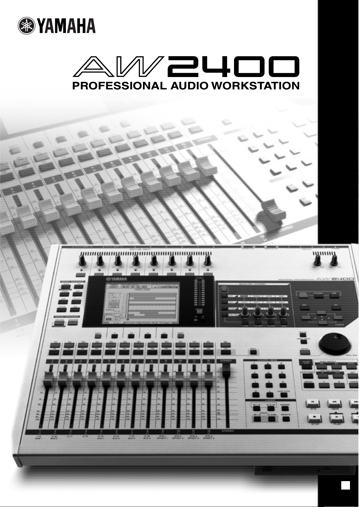
Owner’s Manual
EN
Page 2

FCC INFORMATION (U.S.A.)
1. IMPORTANT NOTICE: DO NOT MODIFY THIS
UNIT!
This product, when installed as indicated in the instructions contained in this manual, meets FCC requirements.
Modifications not expressly approved by Yamaha may
void your authority, granted by the FCC, to use the product.
2. IMPORTANT: When connecting this product to acces-
sories and/or another product use only high quality
shielded cables. Cable/s supplied with this product MUST
be used. Follow all installation instructions. Failure to follow instructions could void your FCC authorization to use
this product in the USA.
3. NOTE: This product has been tested and found to com-
ply with the requirements listed in FCC Regulations, Part
15 for Class “B” digital devices. Compliance with these
requirements provides a reasonable level of assurance
that your use of this product in a residential environment
will not result in harmful interference with other electronic
devices. This equipment generates/uses radio frequencies and, if not installed and used according to the
instructions found in the users manual, may cause interference harmful to the operation of other electronic
* This applies only to products distributed by YAMAHA CORPORATION OF AMERICA. (class B)
devices. Compliance with FCC regulations does not guarantee that interference will not occur in all installations. If
this product is found to be the source of interference,
which can be determined by turning the unit “OFF” and
“ON”, please try to eliminate the problem by using one of
the following measures:
Relocate either this product or the device that is being
affected by the interference.
Utilize power outlets that are on different branch (circuit
breaker or fuse) circuits or install AC line filter/s.
In the case of radio or TV interference, relocate/reorient
the antenna. If the antenna lead-in is 300 ohm ribbon
lead, change the lead-in to co-axial type cable.
If these corrective measures do not produce satisfactory
results, please contact the local retailer authorized to distribute this type of product. If you can not locate the
appropriate retailer, please contact Yamaha Corporation
of America, Electronic Service Division, 6600 Orangethorpe Ave, Buena Park, CA90620
The above statements apply ONLY to those products distributed by Yamaha Corporation of America or its subsidiaries.
COMPLIANCE INFORMATION STATEMENT
(DECLARATION OF CONFORMITY PROCEDURE)
Responsible Party : Yamaha Corporation of America
Address : 6600 Orangethorpe Ave., Buena Park, Calif. 90620
Telephone : 714-522-9011
Type of Equipment : Professional Audio Workstation
Model Name : AW2400
This device complies with Part 15 of the FCC Rules.
Operation is subject to the following conditions:
1) this device may not cause harmful interference, and
2) this device must accept any interference received including interference that may cause undesired operation.
See user manual instructions if interference to radio reception is suspected.
* This applies only to products distributed by
YAMAHA CORPORATION OF AMERICA.
IMPORTANT NOTICE FOR THE UNITED KINGDOM
Connecting the Plug and Cord
WARNING: THIS APPARATUS MUST BE EARTHED
IMPORTANT. The wires in this mains lead are coloured in accordance
with the following code:
As the colours of the wires in the mains lead of this apparatus may not
correspond with the coloured markings identifying the terminals in your
plug proceed as follows:
The wire which is coloured GREEN-and-YELLOW must be connected to
the terminal in the plug which is marked by the letter E or by the safety
earth symbol or colored GREEN or GREEN-and-YELLOW.
The wire which is coloured BLUE must be connected to the terminal
which is marked with the letter N or coloured BLACK.
The wire which is coloured BROWN must be connected to the terminal
which is marked with the letter L or coloured RED.
GREEN-AND-YELLOW : EARTH
BLUE : NEUTRAL
BROWN : LIVE
(FCC DoC)
• This applies only to products distributed by Yamaha-Kemble Music (U.K.) Ltd. (3 wires)
AW2400 Owner’s Manual
2
Page 3
CAUTION
RISK OF ELECTRIC SHOCK
DO NOT OPEN
CAUTION: TO REDUCE THE RISK OF
ELECTRIC SHOCK, DO NOT REMOVE
COVER (OR BACK). NO USER-SERVICEABLE
PARTS INSIDE. REFER SERVICING TO
QUALIFIED SERVICE PERSONNEL.
The above warning is located on the rear of the unit.
IMPORTANT SAFETY INSTRUCTIONS
Explanation of Graphical Symbols
The lightning flash with arrowhead symbol
within an equilateral triangle is intended to
alert the user to the presence of
uninsulated “dangerous voltage” within
the product’s enclosure that may be of
sufficient magnitude to constitute a risk of
electric shock to persons.
The exclamation point within an
equilateral triangle is intended to alert the
user to the presence of important operating
and maintenance (servicing) instructions
in the literature accompanying the product.
1 Read these instructions.
2Keep these instructions.
3 Heed all warnings.
4 Follow all instructions.
5 Do not use this apparatus near water.
6 Clean only with dry cloth.
7 Do not block any ventilation openings. Install in
accordance with the manufacturer’s instructions.
8 Do not install near any heat sources such as
radiators, heat registers, stoves, or other apparatus
(including amplifiers) that produce heat.
9 Do not defeat the safety purpose of the polarized or
grounding-type plug. A polarized plug has two blades
with one wider than the other. A grounding type plug
has two blades and a third grounding prong. The wide
blade or the third prong are provided for your safety. If
the provided plug does not fit into your outlet, consult
an electrician for replacement of the obsolete outlet.
10 Protect the power cord from being walked on or
pinched particularly at plugs, convenience
receptacles, and the point where they exit from the
apparatus.
11 Only use attachments/accessories specified by the
manufacturer.
12 Use only with the cart, stand,
tripod, bracket, or table
specified by the manufacturer,
or sold with the apparatus.
When a cart is used, use
caution when moving the cart/
apparatus combination to
avoid injury from tip-over.
13 Unplug this apparatus during lightning storms or
when unused for long periods of time.
14 Refer all servicing to qualified service personnel.
Servicing is required when the apparatus has been
damaged in any way, such as power-supply cord or
plug is damaged, liquid has been spilled or objects
have fallen into the apparatus, the apparatus has
been exposed to rain or moisture, does not operate
normally, or has been dropped.
WARNING
TO REDUCE THE RISK OF FIRE OR ELECTRIC SHOCK, DO NOT EXPOSE THIS APPARATUS TO RAIN OR MOISTURE.
(98-6500)
This product contains a high intensity lamp that contains a small amount of mercury.
Disposal of this material may be regulated due to environmental considerations.
For disposal information in the United States, refer to the Electronic Industries Alliance web site:
www.eiae.org
* This applies only to products distributed by YAMAHA CORPORATION OF AMERICA.
AW2400 Owner’s Manual
(mercury)
3
Page 4
PRECAUTIONS
PLEASE READ CAREFULLY BEFORE PROCEEDING
* Please keep this manual in a safe place for future reference.
WARNING
Always follow the basic precautions listed below to avoid the possibility of serious injury or even death from
electrical shock, short-circuiting, damages, fire or other hazards. These precautions include, but are not
limited to, the following:
Power supply/Power cord
• Only use the voltage specified as correct for the device. The required
voltage is printed on the name plate of the device.
• Use only the included power cord.
• Do not place the power cord near heat sources such as heaters or
radiators, and do not excessively bend or otherwise damage the cord,
place heavy objects on it, or place it in a position where anyone could
walk on, trip over, or roll anything over it.
• Be sure to connect to an appropriate outlet with a protective grounding
connection. Improper grounding can result in electrical shock.
Do not open
• Do not open the device or attempt to disassemble the internal parts or
modify them in any way. The device contains no user-serviceable parts. If
it should appear to be malfunctioning, discontinue use immediately and
have it inspected by qualified Yamaha service personnel.
Water warning
• Do not expose the device to rain, use it near water or in damp or wet
conditions, or place containers on it containing liquids which might spill
into any openings.
• Never insert or remove an electric plug with wet hands.
If you notice any abnormality
• If the power cord or plug becomes frayed or damaged, or if there is a
sudden loss of sound during use of the device, or if any unusual smells
or smoke should appear to be caused by it, immediately turn off the
power switch, disconnect the electric plug from the outlet, and have the
device inspected by qualified Yamaha service personnel.
• If this device should be dropped or damaged, immediately turn off the
power switch, disconnect the electric plug from the outlet, and have the
device inspected by qualified Yamaha service personnel.
CAUTION
Always follow the basic precautions listed below to avoid the possibility of physical injury to you or others, or
damage to the device or other property. These precautions include, but are not limited to, the following:
Power supply/Power cord
• Remove the electric plug from the outlet when the device is not to be
used for extended periods of time, or during electrical storms.
• When removing the electric plug from the device or an outlet, always
hold the plug itself and not the cord. Pulling by the cord can damage it.
Location
• Before moving the device, remove all connected cables.
• When setting up the device, make sure that the AC outlet you are using is
easily accessible. If some trouble or malfunction occurs, immediately
turn off the power switch and disconnect the plug from the outlet.
•Avoid setting all equalizer controls and faders to their maximum.
Depending on the condition of the connected devices, doing so may
cause feedback and may damage the speakers.
• Do not expose the device to excessive dust or vibrations, or extreme cold
or heat (such as in direct sunlight, near a heater, or in a car during the
day) to prevent the possibility of panel disfiguration or damage to the
internal components.
AW2400 Owner’s Manual
4
• Do not place the device in an unstable position where it might
accidentally fall over.
• The plastic side panels do not provide a secure grip, and should not be
used as handles when moving or transporting the unit. Carrying the unit
by the plastic side panels can result in the unit being dropped, which
could damage the unit and/or cause personal injury.
• Do not block the vents. This device has ventilation holes at the top/front/
rear to prevent the internal temperature from becoming too high. In
particular, do not place the device on its side or upside down. Inadequate
ventilation can result in overheating, possibly causing damage to the
device(s), or even fire.
• Do not use the device in the vicinity of a TV, radio, stereo equipment,
mobile phone, or other electric devices. Doing so may result in noise,
both in the device itself and in the TV or radio next to it.
(5)-4 1/2
Page 5

Connections
Handling caution
• Before connecting the device to other devices, turn off the power for all
devices. Before turning the power on or off for all devices, set all volume
levels to minimum.
• Be sure to connect to a properly grounded power source. A ground screw
is provided on the rear panel of this device for maximum safety and
shock prevention. If the mains outlet is not grounded, be sure to connect
the ground screw to a confirmed ground point before plugging the device
into the mains. Improper grounding can result in electrical shock.
• When turning on the AC power in your audio system, always turn on the
power amplifier LAST, to avoid speaker damage. When turning the power
off, the power amplifier should be turned off FIRST for the same reason.
• Do not insert your fingers or hands in any gaps or openings on the
device (vents, disc slots, etc.).
•Avoid inserting or dropping foreign objects (paper, plastic, metal, etc.)
into any gaps or openings on the device (vents, disc slots, etc.) If this
happens, turn off the power immediately and unplug the power cord from
the AC outlet. Then have the device inspected by qualified Yamaha
service personnel.
• Do not use headphones for a long period of time at a high or
uncomfortable volume level, since this can cause permanent hearing
loss. If you experience any hearing loss or ringing in the ears, consult a
physician.
• Do not rest your weight on the device or place heavy objects on it, and
avoid use excessive force on the buttons, switches or connectors.
XLR-type connectors are wired as follows (IEC60268 standard): pin 1: ground, pin 2: hot (+), and pin 3: cold (-).
Insert TRS phone jacks are wired as follows: sleeve: ground, tip: send, and ring: return.
Yamaha cannot be held responsible for damage caused by improper use or modifications to the device, or data that is lost or destroyed.
Always turn the power off when the device is not in use.
The performance of components with moving contacts, such as switches, volume controls, and connectors, deteriorates over time. Consult qualified Yamaha
service personnel about replacing defective components.
(5)-4 2/2
AW2400 Owner’s Manual
5
Page 6
Caution for Laser
This product utilizes a laser.
Use of control, adjustment or performance of procedures other than those specified herein may result in hazardous radiation exposure.
Do not open covers and do not repair yourself. Refer servicing to qualified personnel.
Laser properties of the Drive
Laser Class : Class 1 (HHS and IEC 825-1)
Wavelength : for CD 784 nm
for DVD 662 nm
The label shown below is located on the rear of this product.
CLASS 1 LASER PRODUCT
The label shown below is located on the top of the internal CD-RW drive.
CAUTION
ATTENTION
VORSICHT
ADVARSEL
ADVARSEL
VARNING
VAR O!
CAUTION: CLASS 3B VISIBLE AND INVISIBLE LASER RADIATION WHEN OPEN. AVOID EXPOSURE TO BEAM.
CLASS 3B VISIBLE AND INVISIBLE LASER RADIATION WHEN OPEN. AVOID EXPOSURE TO BEAM.
CLASSE 3B RAYONNEMENT LASER VISIBLE ET INVISIBLE EN CAS D’OUVERTURE.
EXPOSITION DANGEREUSE AU FAISCEAU.
KLASSE 3B SICHTBARE UND UNSICHTBARE LASERSTRAHLUNG, WENN ABDECKUNG GEÖFFNET.
NICHT DEM STRAHL AUSSETZEN.
KLASSE 3B SYNLIG OG USYNLIG LASERSTRÅLING VED ÅBNING. UNDGÅ UDS/ETTELSE FOR STRÅLING.
KLASSE 3B SYNLIG OG USYNLIG LASERSTRÅLING NÅR DEKSEL ÅPNES. UNNGÅ EKSPONERING FOR STRÅLEN.
KLASS 3B SYNLIG OCH OSYNLIG LASERSTRÅLNING NÄR DENNA DEL ÄR ÖPPNAD. STRÅLEN ÄR FARLIG.
KURSSI 3B NÄKYVÄ JA NÄKYMÄTÖN AVATTAESSA OLET ALTTIINA LASERSÄTEILYLLE, ÄLÄ KATSO SÄTEESEN.
Handling the CD-R/RW media
Please observe the following points when handling the disc.
Failure to do so may cause problems such as the recorded data being lost, the drive to malfunction, or the
printed label to become blurred.
• Do not place the disc in locations of direct sunlight, high temperature, or high humidity.
• Do not touch the recording surface of the disc.
Hold the disc at the edges.
• Gently wipe dust or dirt off of the recording surface of the disc.
Use an air duster or cleaner to remove dust. Vigorously rubbing the surface of the disc with a dry cloth may
scratch the disc.
• If the disc surface needs cleaning, wipe gently from the center to the outside of the disc with a soft damp
cloth, then gently wipe off remaining moisture in the same way with a clean dry cloth.
• Do not write on the disc or affix labels to it.
• Do not wipe the disc with chemicals or detergents.
• Do not bend or drop the disc.
AW2400 Owner’s Manual
6
Page 7

Internal Hard Disk Precautions
• During some hard disk operations a small amount of vibration might be felt at the control panel and you
might hear some mechanical noises. This is normal.
• Do not subject the unit to strong physical shock. Excessive physical shock can damage the internal hard
disk.
•Always turn the power off when moving the unit from one location to another. Data on the internal hard disk
can be lost or corrupted if the unit is moved while the power is on.
Copyright Notice
Copyright and other intellectual property laws in various countries permit reproduction of copyrighted materials under certain requirements. The observance of applicable laws for use of this product, however, is your
responsibility. Yamaha disclaims any liability for violation of such laws in association with the use of this
product.
Although this product is designed for original music production, it can be utilized to make reproduction of
copyrighted music and other sound products. While certain reproduction and use of reproduced materials are
permitted under applicable laws, such reproduction and use without license may constitute copyright infringement and other violation of laws. Since violation of such laws can have serious consequences, you may wish
to consult a legal expert about your planned use of this product.
This product incorporates and bundles computer programs and contents in which Yamaha owns copyrights or
with respect to which it has license to use others’ copyrights. Such copyrighted materials include, without limitation, all computer software, styles files, MIDI files, WAVE data and sound recordings. Any unauthorized use
of such programs and contents outside of personal use is not permitted under relevant laws. Any violation of
copyright has legal consequences. DON’T MAKE, DISTRIBUTE OR USE ILLEGAL COPIES.
The illustrations and LCD screens as shown in this owner’s manual are for instructional purposes only, and may
appear somewhat different from those on your instrument.
AW2400 Owner’s Manual
7
Page 8

Contents
1. Before you start 11
Introduction................................................................. 11
Remember to back up your data ................................ 11
About the built-in CD-RW drive ..................................12
Using the CD-RW drive .............................................. 12
Installing an optional card........................................... 13
2. Introducing the AW2400 15
Features of the AW2400 ............................................15
AW2400 terminology .................................................. 17
Recorder section.................................................... 17
Mixer section.......................................................... 18
Overall.................................................................... 19
Parts of the AW2400 and what they do......................20
Top panel ...............................................................20
Rear panel .............................................................28
Front panel............................................................. 29
Basic operation of the AW2400..................................30
Viewing the display ................................................ 30
Accessing a screen/page....................................... 31
Switching a button on/off........................................ 31
Editing a value in the display .................................31
Using Additional Function Buttons .........................31
Entering text........................................................... 32
Switching Mixing Layers ........................................33
Using the Selected Channel section ......................33
3. Connection and Setup 37
Connection .................................................................37
Turning the power on/off ............................................38
Adjusting the input level .............................................39
4. Listening to the demo song 41
Loading the demo song..............................................41
Playing the demo song...............................................42
5. Recording to a sound clip 43
Recording a sound clip...............................................43
Playing a sound clip ...................................................45
6. Track recording 47
Creating a new song ..................................................47
Direct recording and Mixed recording.........................49
Assigning input signals to tracks
(Direct recording)............................................... 51
Assigning input signals to tracks
(Mixed recording) ..............................................54
Recording on a track...................................................56
Saving the current song..............................................57
Pairing channels .........................................................58
Applying EQ To an Input Signal..................................60
Applying Compression to an Input Signal...................61
Handy Recording Functions .......................................62
Using the Metronome .............................................62
Switching virtual tracks...........................................63
Using the Undo List ................................................64
7. Overdubbing 65
About overdubbing......................................................65
Assigning the input signal to a track ...........................66
Setting the mix balance and pan ................................67
Overdubbing ...............................................................68
Punch-in/out................................................................69
Manual punch-in/out...............................................69
Auto punch-in/out ...................................................70
8. Mixdown and bounce operations 73
About mixdown and bouncing.....................................73
Mixdown procedure ....................................................75
Playing back the stereo track......................................78
Bounce (ping-pong) recording procedure ...................79
Convenient functions for mixdown/bounce .................82
Fader Group assignments......................................82
Mute Group assignments .......................................83
Using the Solo function ..........................................84
9. Transport/Locate Operation 87
The Transport Section Keys .......................................87
Move To a Specified Location ....................................87
Using the locator.........................................................88
Using markers.............................................................90
Adjusting the position of a locate point or marker.......91
Adjusting the position of a locate point...................91
Adjusting the position of a marker ..........................92
Erasing a locate point or marker.................................93
Repeat playback of a specific region
(the A-B Repeat function) ...........................................93
Finding a location while monitoring the sound
(the Nudge function) ...................................................94
Finding a location while viewing the waveform...........95
10. Meters 97
Level Meter Types ......................................................97
AW2400 Owner’s Manual
8
Page 9

Contents
11. Patching and signal flow 99
Input signal patching ..................................................99
Patching for Direct Recording ................................99
Patching for Mixed Recording.............................. 102
Output signal patching.............................................. 104
12. Channel Operation 105
Displaying the mix parameters
for individual channels..............................................105
Channel Library Operation .......................................108
Calling the Channel Library screen...................... 108
Changing Channel Library Names....................... 109
Storing Channel Library settings.......................... 109
Recalling Channel Library settings ......................110
Erasing Channel Library settings .........................110
13. AUX 111
About the AUX buses ............................................... 111
AUX Send Level Adjustment .................................... 111
Using external effects with the AUX buses ..............113
14. Effects 115
About the Internal Effects ......................................... 115
Recalling Effect Library settings ............................... 116
Applying Effects via Send and Return......................117
Inserting an Effect Into a Channel ............................ 119
Editing Effects ..........................................................121
Effect Library Operations.......................................... 122
Call the Effect Library Screen .............................. 122
Changing Effect Library Names ...........................122
Storing Effect Library settings ..............................123
Erasing Effect Library settings ............................. 123
Correcting a Vocal Track (Pitch Fix)......................... 124
15. Track operations and editing 127
About the AW2400’s tracks ...................................... 127
Audio track operations.............................................. 128
About audio tracks ............................................... 128
Viewing all audio tracks .......................................128
Muting a specific audio track................................ 129
Switching the virtual track of an audio track......... 129
Editing virtual track names for an audio track ......130
Stereo track operations ............................................130
About the stereo track.......................................... 130
Recording on the stereo track.............................. 131
Playing back the stereo track............................... 131
Switching the virtual track of the stereo track ......132
Editing the name of a virtual track
for the stereo track ..........................................132
The Trigger Track Function ......................................133
About Trigger Track..............................................133
Using the Trigger Track Function .........................134
Editing tracks ............................................................135
Basic procedure for track editing ..............................136
List of editing command............................................138
ERASE .................................................................138
DELETE ...............................................................138
INSERT ................................................................138
COPY ...................................................................139
MOVE...................................................................140
EXCHANGE .........................................................141
TIME COMP (Time Compression/Expansion)......141
PITCH (Pitch Change)..........................................142
IMPORT CD AUDIO.............................................142
IMPORT CD WAV ................................................142
IMPORT USB WAV..............................................142
IMPORT TRACK ..................................................142
EXPORT...............................................................142
MERGE ................................................................142
Importing audio data/WAV files ................................143
Importing from the CD-RW drive ..........................143
Importing audio data from another song ..............145
16. Pan, EQ, and Dynamics Processing 147
Pan Control...............................................................147
4-band EQ ................................................................149
Dynamics Processing ...............................................151
Using the Gates....................................................151
Using the Compressors........................................152
EQ/Dynamics Processor Library Operation..............154
Accessing the EQ/Dynamics Library screens ......154
Changing EQ/Dynamics Library Names...............156
Recalling EQ/Dynamics Library settings ..............156
Storing EQ/Dynamics Library settings..................157
Erasing EQ/Dynamics Library settings.................157
17. Scene Memory 159
About Scene Memory ...............................................159
Scene Memory Operation.........................................159
Renaming a scene ...............................................160
Recalling scene data............................................160
Storing scene data ...............................................161
Deleting scene data..............................................161
Protecting a scene................................................161
Using the Recall Safe function..................................162
Moving scenes..........................................................163
AW2400 Owner’s Manual
9
Page 10

Contents
18. Song management 165
About songs .............................................................165
Managing Your Songs..............................................167
Editing various settings for the song ........................174
Creating a tempo map..............................................175
Backing up songs ..................................................... 177
Restoring songs .......................................................178
Exchanging Song Data
With Other AW-series Audio Workstations............... 180
19. Automix 181
About Automix .......................................................... 181
Automix Operation.................................................... 181
Creating a New Automix Recording.....................182
Recording the Automix Data ................................ 183
Automix Playback ................................................185
Punch In and Out of Automix ............................... 185
Command Editing Automix data
In a Specified Region ...............................................186
Editing Individual Automix Events ............................188
Automix Library Operation........................................ 190
About the Automix Library Page .......................... 190
Changing Automix Names ................................... 190
Storing Automix settings ...................................... 191
Recalling Automix settings................................... 191
Erasing Automix settings .....................................191
Protecting Automix Data ...................................... 192
20. MIDI 193
What you can do using MIDI ....................................193
Basic MIDI Settings .................................................. 194
MIDI Synchronization Message Setup .....................198
Connecting to External Equipment........................... 200
Synchronizing the AW2400
With External MIDI Devices............................. 200
Switching AW2400 scenes
from an external MIDI device ..........................201
Recording/playing AW2400
mix operations on an external sequencer .......202
Using the MIDI Remote function ..............................204
About the MIDI Remote function.......................... 204
Using the MIDI Remote function presets ............. 204
Using User-defined Remote function ................... 206
Remotely controlling a tone generator module .... 207
21. Utility functions 209
Using the test tone oscillator ....................................209
AW2400 Preferences ...............................................210
Initializing the internal hard disk ...............................212
22. Creating an audio CD 213
Creating an audio CD ...............................................213
Types of media that you can use
with the CD-RW drive ...............................................213
Writing an audio CD..................................................214
Basic settings for the CD-RW drive ..........................215
Writing audio data.....................................................216
Writing Track At Once ..........................................217
Writing Disc At Once ............................................218
Finalizing CD-R/RW media.......................................220
Erasing CD-RW media .............................................221
Playing an audio CD .................................................222
23. Digital Input/Output &
Optional Card Settings 223
Wordclock and Cascade Settings.............................223
Select the Wordclock Source ...............................223
Fine Adjustment Of Overall
Song Pitch (Vari-pitch).....................................226
Cascade-connecting External Devices.................226
Check the Status Of the Digital Input Signal.............227
Plug-in Card Settings................................................228
24. USB 229
What You Can Do With USB ....................................229
WAV File Transfer (USB Storage Mode) ..................230
Switching to the USB Storage Mode....................230
Exiting the USB Storage Mode.............................232
Copying Exported WAV Files
To the Computer..............................................233
Importing Copied WAV Files
From the Computer..........................................234
Appendix 237
Mastering library list..................................................237
EQ Parameter list .....................................................238
Dynamics Parameters ..............................................240
Gate Parameter list...................................................243
Compressor Parameter list .......................................243
Effects Parameters ...................................................245
Troubleshooting ........................................................258
Display message list .................................................263
About the CD-ROM included with the AW2400 ........266
MIDI data format .......................................................272
MIDI Implementation Chart.......................................276
Specifications............................................................277
Dimensions ...............................................................279
Index .........................................................................280
Block diagram ...........................................................284
AW2400 Owner’s Manual
10
Page 11

Chapter 1
■ Trademarks
■ Yamaha Website (English only)
■ Yamaha Manual Library
■ Responsibility for loss of data, etc.
Before you start
This chapter explains what you should know before you begin using the
AW2400.
Introduction
■ Check the included items
The AW2400 package contains the following items. If any
are missing, please contact your dealer.
• The AW2400
•Power cord
• Owner’s manual (this book)
• CD-ROM
■ Copyright
Copying of commercially available music sequence data
and/or digital audio files for any purpose other than your
own personal use is strictly prohibited.
• Macintosh is a registered trademark of Apple Computer,
Inc. USA in the United States and other countries.
• Windows is a registered trademark of Microsoft Corporation USA in the United States and other countries.
• Cubase SX and Nuendo are trademarks of Steinberg
Media Technologies AG.
• Logic is a registered trademark of Apple Computer, Inc.
USA in the United States and other countries.
• SONAR is a registered trademark of Twelve Tone Systems, Inc.
• ProTools is a trademark or registered trademark of Avid
Technology, Inc. and affiliated companies.
• Other company names and product names in this document are the trademarks or registered trademarks of
their respective owners.
1
Before you start
Remember to back up your data
■ Storing produced data
Produced data can be lost due to breakdown or mistaken
operation. We recommend that you store all important
data on your computer, CD-R/CD-RW discs, or other
external storage medium.
http://www.yamahasynth.com/
http://www.yamaha.co.jp/manual/
Yamaha will accept no responsibility for any damages
(including consequential or incidental) incurred by the
customer or any third party as a result of loss or impairment of the data stored on the hard disk or CD-R media,
regardless of whether such loss could have been or actually was foreseen by Yamaha.
Nor does Yamaha guarantee the media against any defect
that may render it unusable.
AW2400 Owner’s Manual
11
Page 12
About the built-in CD-RW drive • Using the CD-RW drive
About the built-in CD-RW drive
1
A built-in CD-RW drive is a device that lets you create or
Before you start
play audio CDs, backup and restore data from the internal
hard disk, and read data from a CD-ROM.
IMPORTANT
• Even if a CD-RW drive is operating normally, it may fail a read
or write operation approximately once in five hundred times.
•Yamaha will take no responsibility for any damages, direct or
consequential, that may result from the use of the above CDRW drive.
■ Handling
1 Never touch the objective lens.
B Be careful that the objective lens does not become
dusty or dirty.
C If the objective lens becomes dusty, use a commer-
cially available blower etc. to blow the dust off with
clean air.
D Since the inside of the drive contains powerful mag-
netic circuitry, do not allow any magnetic material to
come near the drive. (In particular, any metallic fragments, screws, or pins that enter the drive mechanism
will cause operation to fail.)
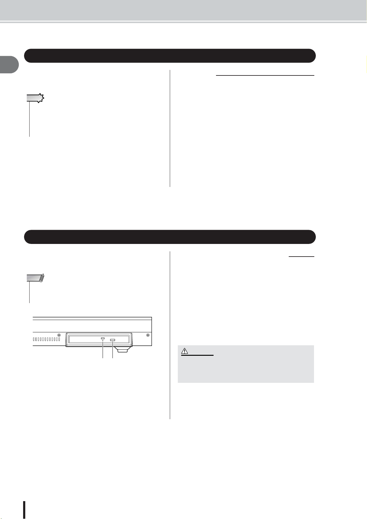
Using the CD-RW drive
To insert a disc into the CD-RW drive, press the eject
switch. The disc tray will open. Place the disc on the tray,
and gently push the disc tray in.
NOTE
• The disc tray is ejected electrically. If the disc tray is not ejected
when you press the eject switch, turn on the power of the AW2400
and press the eject switch once again.
Eject switchEject hole
■ Removing a CD in an emergency
If you are unable to remove the disc by pressing the eject
switch, insert a wire of less than 2 mm diameter (such as a
straightened paper clip) into the eject hole, and push gently. However, pressing the eject switch will not eject the
disc when the AW2400 is in the following states, so do not
use this method in such cases.
• When the AW2400’s power is “OFF”
• When the disc is being accessed (data is being read,
written, or erased)
• While in CD PLAY mode
CAUTION
• This removal method is for use in emergencies such as when
you cannot remove the disc due to a malfunction of the disc
tray or a power failure. Do not use this method unnecessarily,
since doing so will damage the CD-RW drive.
AW2400 Owner’s Manual
12
Page 13
Installing an optional card
■ Available optional cards
By installing a separately sold mini-YGDAI card in a rearpanel slot, you can add analog input/output jacks to the
AW2400 or allow connection of external digital devices.
The following types of cards can be used.
Card type Model
MY4-AD 4
AD card
DA card
Digital I/O card
Waves Plug-in
DSP card
mLAN card MY16-mLAN 16 IEEE1394 24bit
MY8-AD
MY8-AD24
MY8-AD96
MY4-DA 4
MY8-DA96 8 24 bit
MY8-AE
MY8-AE96
MY8-AE96S
MY16-AE 16
MY8-AT 8
MY16-AT 16
MY8-TD 8
MY16-TD 16
Y96K 8 ADAT 24bit
Number of
channels
8
8
Refer to the Yamaha Pro Audio global website for the
most recent information on I/O cards.
http://www.yamahaproaudio.com
Digital
format
—
—
AES/EBU
ADAT
TASCAM
Bit
depth
24 bit
20 bit
24 bit
20 bit
24 bit
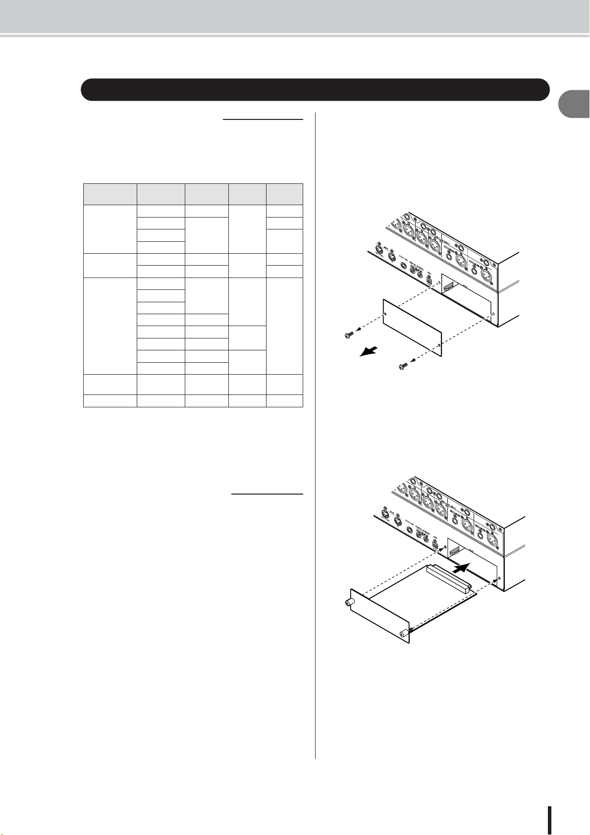
Installing an optional card
To install an optional mini-YGDAI card, proceed as
follows.
Make sure that the power is turned off.
1
Loosen the screws that hold the slot cover
2
in place, and remove the slot cover.
Keep the removed slot cover in a safe place.
Align the edges of the card with the guard
3
rails inside the slot, and insert the card into
the slot.
Push the card all the way into the slot so that the connector at the end of the card is correctly mated with the
connector inside the slot.
1
Before you start
■ Installing an optional card
Before installing a card, you must check the Yamaha website to make sure that this device is compatible.
http://www.yamahaproaudio.com
Use the screws included with the card to
4
fasten the card in place.
Malfunctions or incorrect operation may occur if the
card is not fastened.
AW2400 Owner’s Manual
13
Page 14

1
Before you start
AW2400 Owner’s Manual
14
Page 15
Chapter 2
Introducing the AW2400
This chapter describes the features of the AW2400, the name of each part
and its function, and introduces terminology you need to know when using
the AW2400.
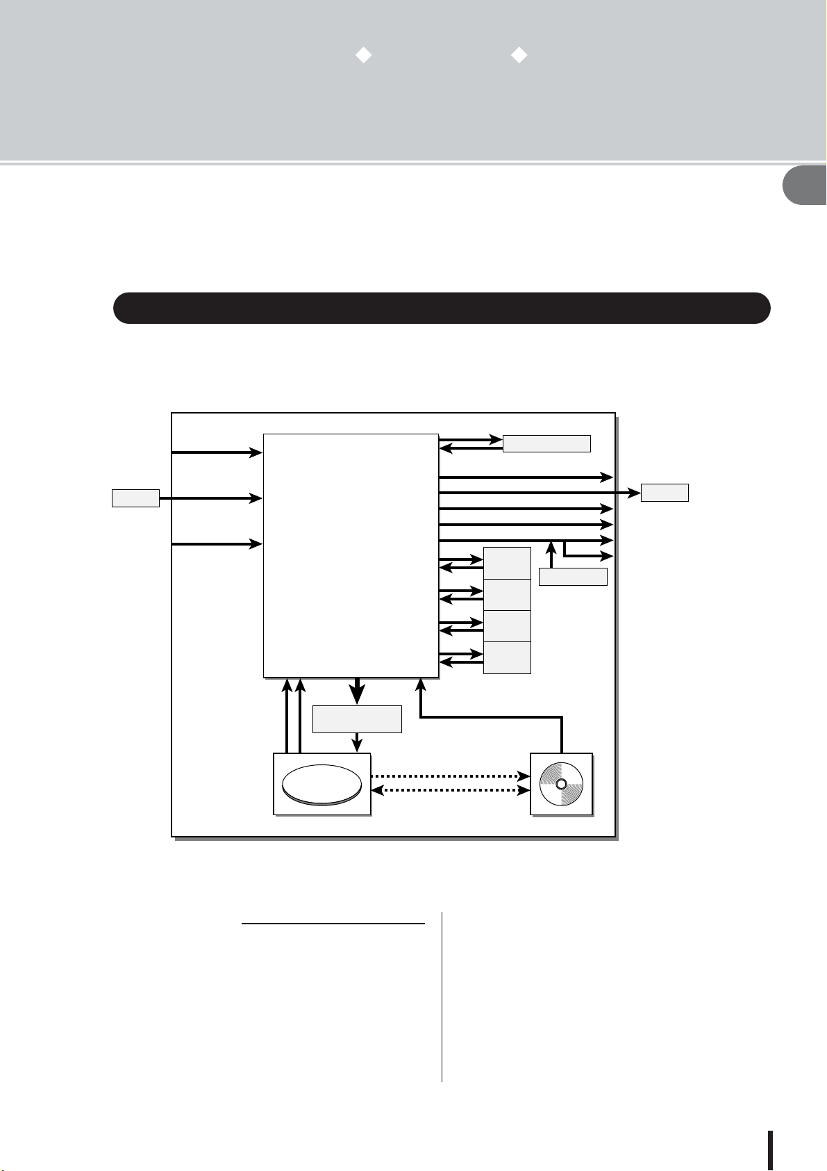
Features of the AW2400
The AW2400 is an audio workstation that combines a digital mixer, multi-effect processor, hard
disk recorder, and CD-RW drive.
The following diagram shows the signal flow within the AW2400.
[MIC/LINE
INPUT]
jacks 1–8
I/O card
[DIGITAL
STEREO IN]
connector
I/O slot
×8
Input channels 1–16
Tr ack channels 1–24
×16
Effect return channels 1–4
×2
Bus1 L/R, Bus2 L/R
AUX buses 1–4
Effect buses 1–4
Stereo buses L/R
Stereo output channel
Mixer
×2
×2
×4
×16
×2
×2
×2
2
×
×
2
×
2
×
2
2
×
×2
Effect 1
×2
Effect 2
×2
Effect 3
×2
Effect 4
Internal Effects
Sound clip
[OMNI OUT] jacks 1-4
I/O card
[DIGITAL STEREO OUT] connector
[STEREO OUT] jacks
[MONITOR OUT] jacks
[PHONES] jack
Metronome
2
Introducing the AW2400
Recorder input
patching
×
24 ×24×2
CD Write
Data Backup/Restore
WAV File Import
Recorder CD-R/RW drive
CD Play
Now let’s take a more detailed look at each section of the AW2400.
■ Mixer section
● Plenty of input channels with professional
features
The AW2400 digital mixer features 24-bit AD/DA conversion with 32-bit internal processing for uncompromised
sound quality. 16 input channels, 24 track channels, and 4
stereo effect return channels provide plenty of input
capacity for most mixing situations.
The 8 AD input ([MIC/LINE INPUT] jacks 1–8), channels 1–16 on an optional I/O card installed in I/O slot, or
the stereo [DIGITAL STEREO IN] connector can be
selected for input.
The track channel 1–24 inputs are permanently assigned
to tracks 1–24, and the effect return channel 1–4 inputs are
permanently assigned to the outputs of internal effect processors 1–4.
AW2400 Owner’s Manual
15
Page 16

Features of the AW2400
● Totally redesigned operation
The AW2400 is designed to be operated directly by the
musician (guitarist, vocalist, drummer etc.). Input signal
track assignment, mixdown and bounce recording settings, tracking with effects/EQ/dynamics, compressor set-
2
tings, and much more can be easily handled with simple,
Introducing the AW2400
straightforward operation.
● Four-band EQ and dynamics processors on
each channel
Four-band full-parametric EQ and dynamics processing is
provided on virtually every channel. You can recall the
desired preset from the library, and use the panel knobs
and keys to quickly adjust the settings.
● Four high-quality multi-effect units built-in
The four built-in effect units deliver a wide variety of
effects including ambience effects such as reverb and
delay, modulation type effects such as chorus and flanger,
and guitar-type effects such as distortion and amp simulation. These effects can be used either via send/return, or
inserted into a desired channel.
● Automix capability
Full automix production power is provided with 13 motor
faders for comprehensive fader control, pan control, scene
recall and library recall capability.
● I/O slot for expansion with optional I/O cards
Expanded inputs and outputs can be provided in ADAT,
TASCAM, AES/EBU, and other formats. Optional DSP
cards can also be used to provide extra signal processing
capability via the I/O slot.
■ Recorder section
● 16-track Simultaneous Recording & 24-track
Simultaneous Playback (16-bit songs)
You can record multiple instrument tracks one by one, or
set up multiple mics to record a drum set or a live performance by an entire band. A stereo track for direct mixdown of all 24 tracks is also provided, letting you manage
the multi-track audio and the two-track mix as a single
data package.
8 virtual tracks are available for the recorder tracks as well
as the stereo track. When recording parts or when doing a
mix, you can switch virtual tracks to record multiple takes
and select the best take later.
The “bit depth” (number of quantization bits) of the audio
data recorded on each track can individually be set to 16
or 24 bits for each song. 16-bit songs allow simultaneous
recording of up to 16 tracks, and simultaneous playback of
up to 24 tracks. 24-bit songs allow simultaneous recording
up to 8 tracks, and simultaneous playback of up to 12
tracks (→ p. 165).
The recording sampling frequency can also be set to either
44.1 kHz or 48 kHz (the selected sampling has no effect
on the number of simultaneous record or playback tracks).
● Trigger track function
The “Trigger Track” function allows the track [ON] keys
and faders to be used to start and stop playback of
recorded tracks. This is ideal for performance situations in
which you want to switch phrases or patterns in real time,
or when you need to start background music on cue, for
example.
● Versatile editing functionality
Audio data recorded on a track can be copied, moved, or
edited using a variety of commands. You can make
detailed edits, or even make radical changes to the structure of the song by using the same riff repeatedly or
increasing the number of choruses.
“Time Compression” lets you compress or expand the
time axis of the audio data over a range of 50%–200%.
“Pitch Change” lets you modify the pitch over a range of
up or down one octave. You can use the Undo function to
undo the results of as many as the last fifteen editing operations.
● A variety of Locate methods, and auto
punch-in/out
Eight locate points (start/end, relative zero, A/B, in/out,
quick locator) and 99 markers can be assigned at any
desired point in the song for quick access via Locate operations. Auto punch-in/out and A-B repeat playback functions are also provided. The AW2400 also has a
metronome that follows the tempo map.
● Sound Clip function
The Sound Clip function lets you record and play back an
input signal without using the recorder tracks. You can use
this function to make quick sketches of song or arrangement ideas. You can transfer recorded sound clip data to
the recorder as required.
● Vocal Editing with Pitch Fix
A Pitch Fix function is provided to allow precise adjustment of the pitch of a vocal track as well as the generation
of chorus parts from a main vocal line. This feature can
also be used to change the character of a vocal sound.
AW2400 Owner’s Manual
16
Page 17
■ Connecting to a Computer
1
2
3
4
5
6
7
8
1
2 3 4 5 6 7 8
1
2
3
4
5
6
7
8
21 22 23 24
Audio tracks
Stereo track
Virtual tracksVirtual tracks
Features of the AW2400 • AW2400 terminology
■ CD-RW drive
A dedicated CD-RW drive is installed in the AW2400. You
can produce an audio CD containing the stereo mixes of
songs recorded on the hard disk. Markers assigned within
a song can also be used as the CD track numbers. You can
even use advanced techniques such as assigning more than
one track number within a single song. The CD-RW drive
can also be used to backup/restore songs, to play back
audio CDs, and to load WAV data from a CD-ROM.
The AW2400 can be directly connected to a computer via
the built-in USB interface, which enables transferring
audio files as well as MIDI messages. This allows WAVformat audio files to be copied between the AW2400 and
computer for convenient management and processing in
computer-based applications, and “backup” song files can
be stored on the computer’s memory media.
AW2400 terminology
Here’s a quick overview of terminology used with the AW2400.
2
Introducing the AW2400
Recorder section
■ Tracks
A location where data is recorded is called a “track.” The
AW2400’s recorder section uses the following types of
track.
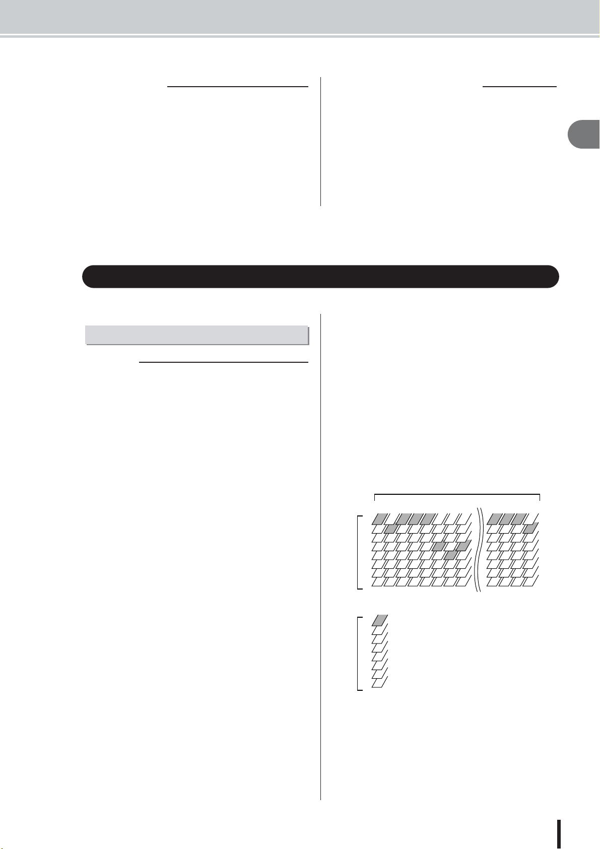
● Audio tracks
The physical tracks used to record and play back audio
data are called “audio tracks,” or simply “tracks.” The
AW2400 has 24 audio tracks. You can record 16 tracks
simultaneously, and play back 24 tracks simultaneously
(16-bit songs).
● Stereo track
The AW2400 has a “stereo track” that is independent from
audio tracks 1–24, and which records and plays a stereo
audio signal. The stereo track is used mainly as a dedicated mixdown track for recording the final mix.
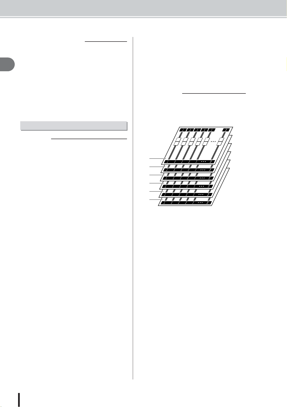
● Virtual tracks
Each of the 24 audio tracks and the stereo track consists of
eight “virtual” tracks. For the audio tracks and the stereo
track, only one virtual track can be recorded or played at
any time. However, you can switch virtual tracks to continue recording other takes while preserving the previously-recorded content.
The diagram below shows the concept of virtual tracks.
The horizontal rows indicate audio tracks 1–24, and the
vertical columns correspond to virtual tracks 1–8. The
shaded areas indicate the virtual track that is currently
selected for recording or playback.
● Trigger tracks
The “Trigger Track” function allows the track [ON] keys
and faders to be used to start and stop playback of
recorded tracks. When the Trigger Track function is
engaged and you press a track channel [ON] key, the corresponding track will playback one time from the beginning of the song to the end of the recorded data.
AW2400 Owner’s Manual
17
Page 18
AW2400 terminology
■ Locate points/markers
Locations within a song that you specified in order to execute a function such as auto punch-in/out or A-B repeat
playback are called “locate points.” Locate points include
2
in/out points and the A/B points. You can use the Locate
section keys to move instantly to these points.
Introducing the AW2400
You can assign “markers” at desired locations within a
song independently of the locate points so that you can
find these locations quickly. The AW2400 lets you set up
to ninety-nine markers (1–99). By using the keys Locate
section you can move instantly to the previous or next
marker.
Mixer section
■ Channels
A signal path that processes a single signal within the
mixer and sends it to various sections is called a “channel.”
The mixer section of the AW2400 provides the following
channels.
● Input channels 1–16
Input channels provide level control, EQ, and dynamics
processing for signals that are input via the [MIC/LINE
INPUT] jacks 1–8, the [DIGITAL STEREO IN] connector, and/or an I/O card installed in the rear-panel slot, and
send them to the recorder tracks or to the [STEREO OUT]
jacks.
● Track channels 1–24
These channels provide level adjustment, EQ, and dynamics processing for the audio playback signals from audio
tracks 1–24 of the recorder, and send the signals to the stereo track and the [STEREO OUT] jacks. You can also perform “bounce recording” by sending these channels to
different tracks.
● Effect return channels 1–4
These channels send the signals returned from the internal
effects to the stereo track and the [STEREO OUT] jacks.
● Stereo output channel
This channel provides level adjustment, EQ, and dynamics
processing for the stereo bus signal (which carries the mix
of the other channels), and sends it to the stereo track or to
the [STEREO OUT] jacks. The same signal is also output
from the [MONITOR OUT] jacks and from the
[PHONES] jack.
● AUX send master channels 1–4
Provide final level adjustment for the AUX buses, as well
as EQ and dynamics processing.
● Effect send master channels 1–4
Provide final level adjustment for the effect buses, as well
as dynamics processing.
■ Mixing Layers
In order to efficiently handle numerous input channels the
AW2400 mixer section channels are organized in “mixing
layers”. The diagram shows an overview of the AW2400’s
6 mixing layers.
A
B
C
D
E
F
The channels available in each of the mixing layers are as
follows.
1 Mixing Layer IN 1-8
Input channels 1–8 and effect return channels 1–4.
B Mixing Layer IN 9-16
Input channels 9–16 and effect return channels 1–4.
C Mixing Layer MASTER
Bus master channels 1/2, AUX send master channels 1–4,
and effect send master channels 1–4.
D Mixing Layer TRACK 1-12
Track channels 1–12.
E Mixing Layer TRACK 13-24
Track channels 13–24.
F REMOTE Layer
A special layer for remote control of external MIDI
devices.
● Bus master channels 1/2
Provide level adjustment, EQ, and dynamics processing
for the signals from bus 1 and bus 2, and sends the signals
to the audio tracks.
AW2400 Owner’s Manual
18
Page 19

■ Mix Parameters
Overall
■ Songs
■ Scenes and scene memories
■ Libraries
■ Tempo map
■ System data
Channel pan, EQ, dynamics processor and other settings
are known as “mix parameters”. All mix parameters can
be saved together as “scenes” that can be recalled whenever necessary. Furthermore, specialized libraries are provided for various parameter groups – EQ, effects, etc. –
that can be saved and recalled individually for each channel.
■ Paired channels
For effect return channels 1–4, stereo output channel, and
bus master channel 1–2, the parameters (except for pan)
are always linked for adjacent pairs of channels. These are
called “paired channels.”
For input channels 1–16, track channels 1–24, and AUX
send master channels 1–4, you can also assign adjacent
odd-numbered/even-numbered channels to function as
paired channels. The parameters (except for pan and
phase) of paired channels will be linked, so that adjusting
one parameter will cause the same parameter of the other
channel to be adjusted accordingly.
■ Buses
A signal route that mixes the signals from multiple channels and sends them to an output jack or recorder track
input is called a “bus.”
Unlike channels, which handle only a single signal, a bus
can combine multiple signals into one or two (stereo) outputs and send them to a destination.
The AW2400’s mixer section provides the following
buses.
AW2400 terminology
The smallest unit by which the AW2400 manages a composition is called a “song.” When you save a song on the
hard disk, all data necessary for reproducing that song will
be saved; i.e., not just the audio data, but also the mixer
settings and the automix settings. You can return to the
original state at any time by loading the saved song.
A “scene” is a stored set of settings for the mixer section
and effects. The area of memory that holds the scenes is
called “scene memory,” and 99 scenes can be stored for
each song. Scene memories are saved on the hard disk as
part of the song.
A “library” is an area of memory that stores individual settings such as for EQ or dynamics. The AW2400 has separate libraries for EQ, dynamics, effect, channel, and
mastering settings.
Recalling a scene affects all mixer section settings, while
the libraries allow only specified settings to be recalled as
required. You can also save the settings from one channel
and copy them to other channels, for example.
Each library is saved on the hard disk as part of the song.
2
Introducing the AW2400
● Stereo bus
This bus mixes the input signals to stereo, and sends them
via the stereo output channel to the stereo track of the
recorder or to the [STEREO OUT] jacks. Normally the
same signal output via the [STEREO OUT] jacks is also
output via the [MONITOR OUT] and [PHONES] jacks.
● AUX buses 1–4
These buses mix the signals from the track, input, and
effect return channels and send them to the specified output connector. Use these when you will use an external
effect processor, or to create a mix differing from the stereo channel for musicians to monitor.
● Effect buses 1–4
These buses combine the signals from the track and input
channels, and input them to built-in effects 1–4.
● Bus 1, Bus 2
These buses mix track, input, and effect return channels
and send them to the inputs of free tracks. Bus 1 and bus 2
are used for bounce (ping-pong) recording.
The “tempo map” records changes in tempo and time signature that occur during the course of a song. The tempo
map is saved on the hard disk as part of the song.
Various global settings that apply to all songs are collectively referred to as “system data.” System data is stored
on the hard disk independently of the individual songs.
AW2400 Owner’s Manual
19
Page 20
Parts of the AW2400 and what they do
Parts of the AW2400 and what they do
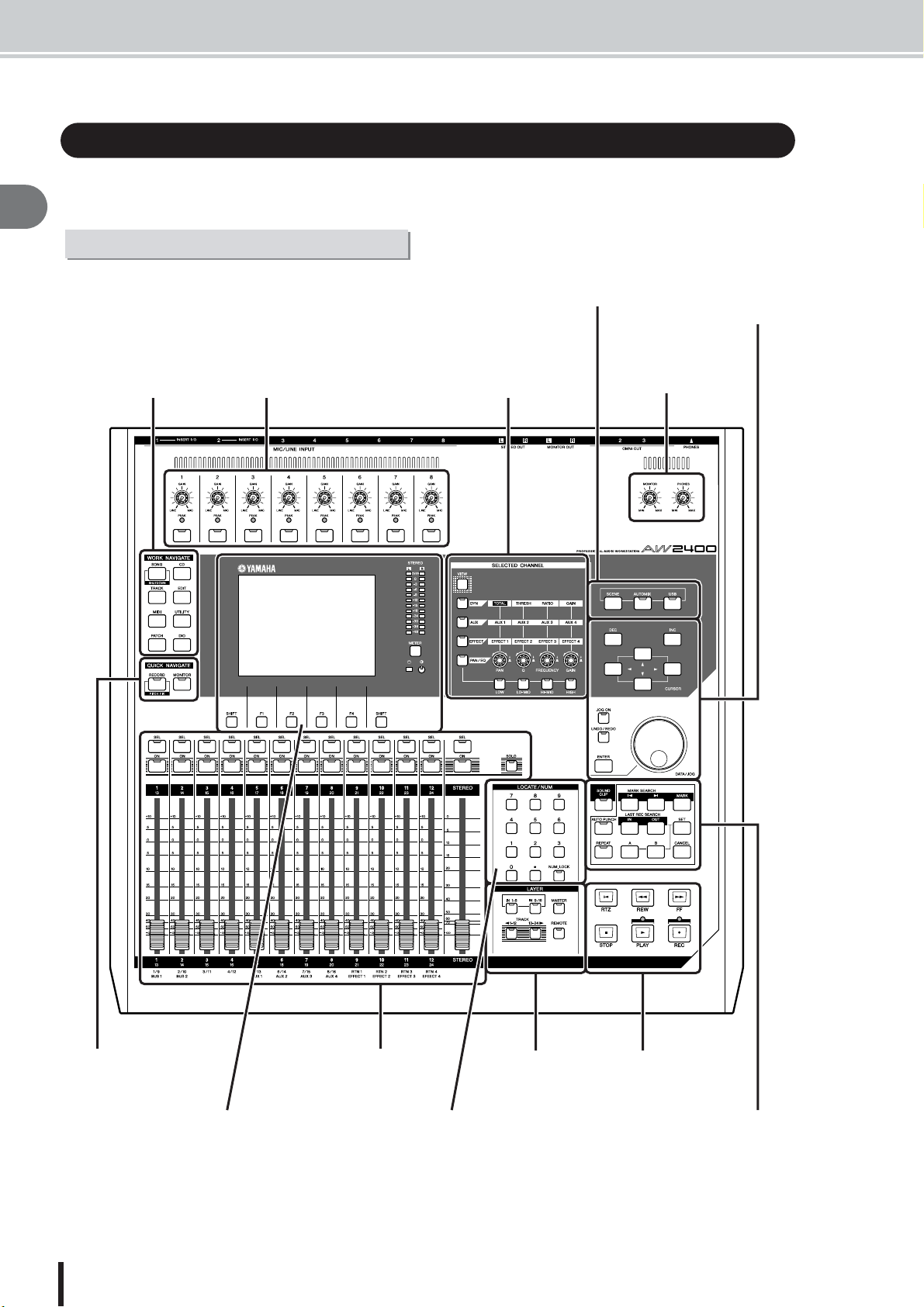
This section explains the names and functions of the various items on the AW2400’s top panel,
rear panel, and front panel.
2
Introducing the AW2400
Top panel
Scene/Automix/USB section (P. 24) Data entry/control
section (P. 25)
Work Navigate
section (P. 21)
Analog Input section (P. 21)
Selected Channel
section (P. 24)
Monitor section (P. 24)
Quick Navigate section
(P. 21)
AW2400 Owner’s Manual
20
Display section (P. 22)
Mixer section (P. 23)
Locate/Number section (P. 25)
Layer section (P. 26)
Tr ansport section
(P. 27)
Locate section (P. 27)
Page 21
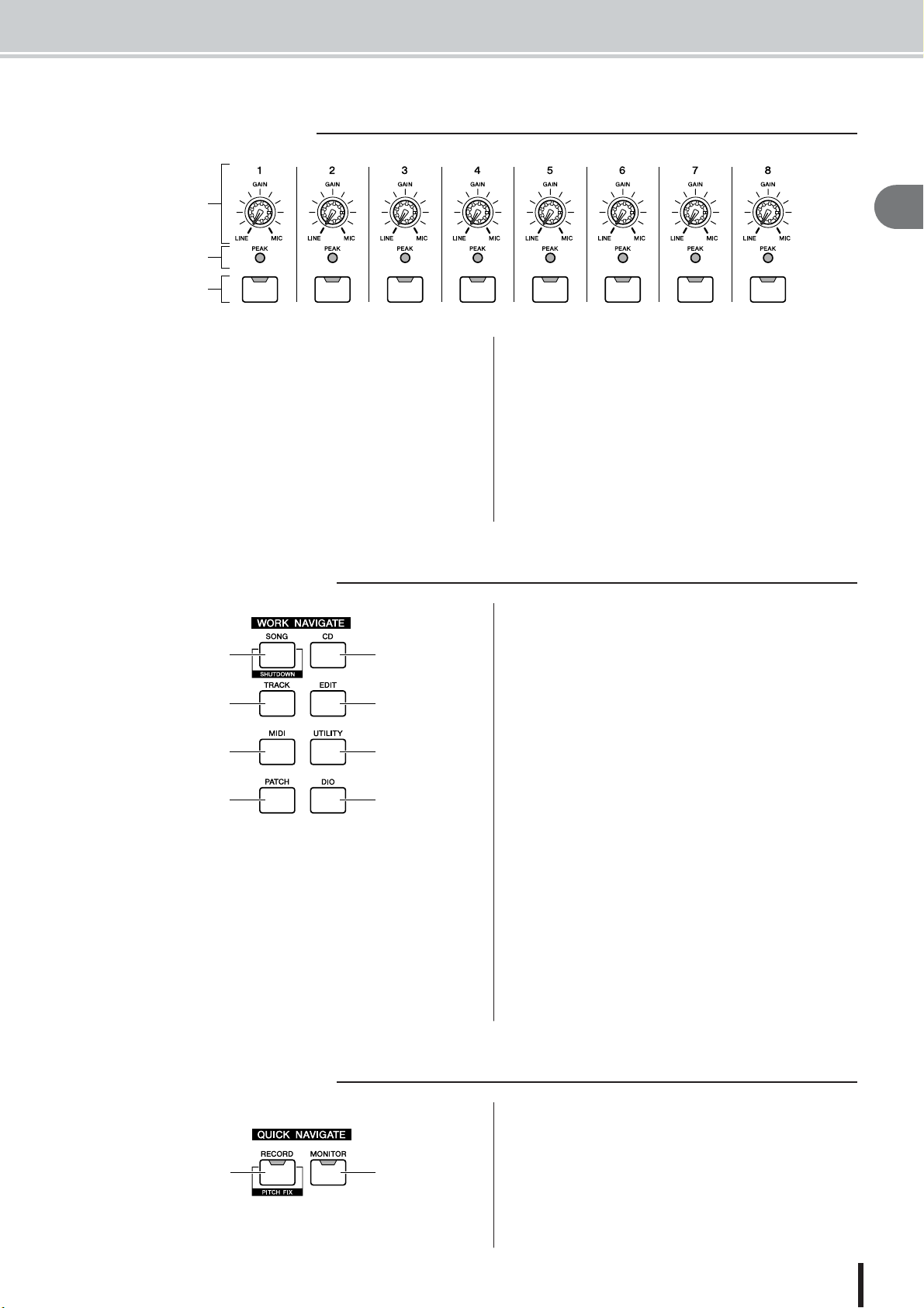
■ Analog Input section
Parts of the AW2400 and what they do
1
2
C
1 [GAIN] knobs 1–8
These adjust the sensitivity of the rear panel MIC/LINE
INPUT jacks 1–8 to input signals.
B [PEAK] Indicators
These indicators will light red if the peak signal level after
the [GAIN] knob reaches or exceeds 3-dB below clipping.
To set the optimum record level, set the [GAIN] knob so
that the indicator flashes only briefly on the highest peaks
that will be encountered during the recording.
■ Work Navigate section
1
3
5
G
1 [SONG] key
This key accesses the SONG screen, where you can save
or load songs, and perform the shut-down procedure.
B [CD] key
This key accesses the CD screen, where you can write or
play an audio CD, and backup or restore data.
2
4
6
H
C [INPUT SEL] keys 1–8
These keys select the mixer input channel that you will
operate.
C [TRACK] key
This key accesses the TRACK screen, where you can
check whether each track contains data, and switch the
virtual tracks that will be used for recording and playback.
D [EDIT] key
This key accesses the EDIT screen, where you can copy or
erase tracks.
E [MIDI] key
Accesses the MIDI screen where you can set up MIDI
synchronization, scene change, and other settings.
F [UTILITY] key
Press this key to access the UTILITY screen with settings
for the unit’s test tone oscillator, digital inputs and outputs, and other utility parameters.
G [PATCH] key
Accesses the PATCH screen where you can patch output
signals as required.
H [DIO] key
The [DIO] key accesses the DIO screen which includes
the clock source and I/O card settings.
2
Introducing the AW2400
■ Quick Navigate section
1
2
1 [RECORD] key
This key accesses the RECORD screen, where you can
quickly assign the signal to be recorded to the input of
each track, and make settings for recording.
B [MONITOR] key
The MONITOR screen, accessed by this key, includes settings for fader grouping, the solo function, and more.
AW2400 Owner’s Manual
21
Page 22
Parts of the AW2400 and what they do
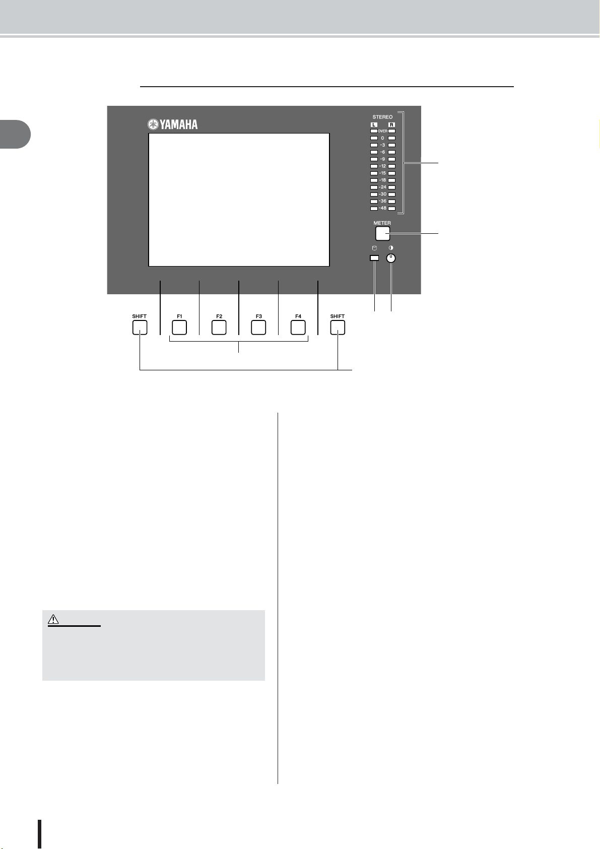
■ Display section
2
Introducing the AW2400
2
1
C
E4
6
1 Display
The backlit display screen provides easy visual access to
all functions and parameters.
B Stereo Meters
These 12-segment levels meters show the final output signals levels on the stereo bus.
C [METER] key
Calls the METER screen which includes the channel, bus,
and other level meters.
D Contrast
Adjusts the brightness of the display.
E Access indicator
This indicator indicates the access status of the internal
hard disk. When the hard disk is being read or written, this
indicator will light.
CAUTION
•Never turn off the power of the AW2400 when the access indicator is lit. Doing so will not only damage the data on the
internal hard disk, but may also damage the hard disk itself.
When you want to turn off the power of the AW2400, you must
perform the shutdown procedure (
→
p. 38).
G
F [F1]–[F4] keys
These keys operate the “tabs” shown at the bottom of the
display screen. They can access other pages in a group of
functions, or in some cases execute specific functions.
G [SHIFT] key
“Shifts” the function of the tabs at the bottom of the display to show additional functions, when applicable. “Shift
functions” can be executed by pressing the appropriate
functions key – [F1] to [F4] – while holding the [SHIFT]
key.
AW2400 Owner’s Manual
22
Page 23
■ Mixer section
• The [STEREO SEL] keys, [STEREO ON] keys, and [STEREO]
faders always operate stereo channels. These keys and faders are
not affected by the LAYER section settings.
Parts of the AW2400 and what they do
1C B D G
2
Introducing the AW2400
E6
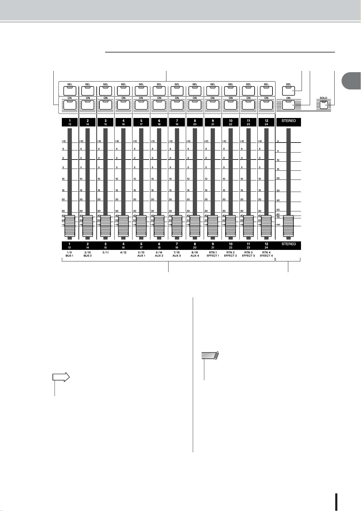
1 [SEL] keys 1–12
B [STEREO SEL] key
Selects the channel to be operated. The [SEL] key of the
currently selected channel will light.
C [ON] keys 1–12
D [STEREO ON] key
Turns the corresponding channel ON or OFF. The [ON]
key will be lit when the corresponding channel is ON, and
out when the channel is OFF. The [ON] keys are also used
to specify solo channels when the solo function is on.
HINT
• When Trigger Track mode is engaged, the [ON] key can be used to
start/stop playback of the corresponding track.
E Faders 1–12
The faders adjust recorder track playback levels, input
channel input levels, and effect return channel input levels
according to the mixing layer currently selected via the
LAYER section.
F [STEREO] fader
Adjusts the output level of the stereo bus.
NOTE
G [SOLO] key
Turns the solo function ON or OFF.
AW2400 Owner’s Manual
23
Page 24
Parts of the AW2400 and what they do
■ Selected Channel section
2
1
Introducing the AW2400
B
C
D
E
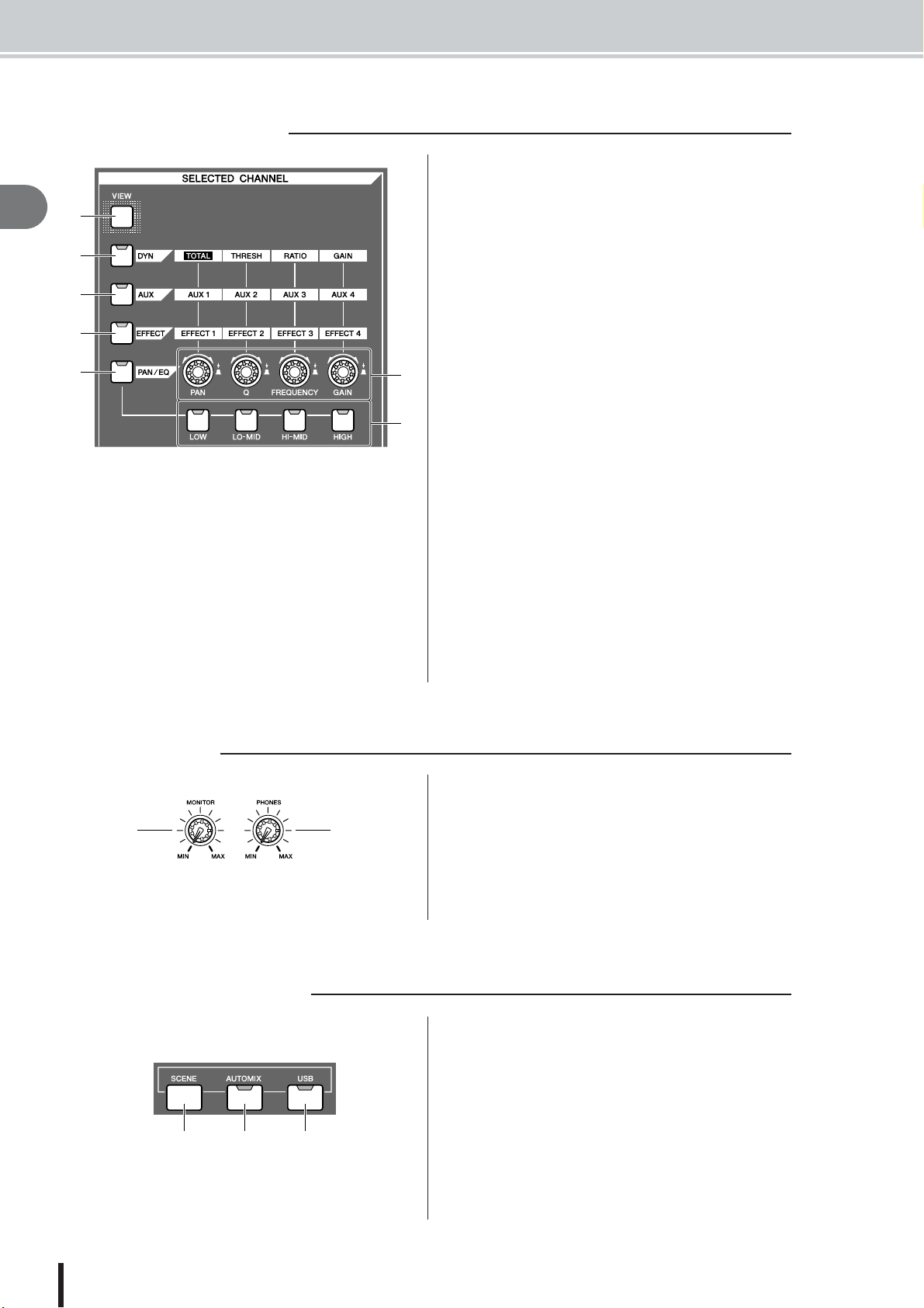
1 [VIEW] key
This key accesses the CH VIEW screen, where you can
check the level of each channel, or perform on-screen
adjustments to the faders and other mix parameters of
each channel.
B [DYN] key
Calls the DYNAMICS screen for the currently selected
channel. You can then press any of the SELECTED
CHANNEL knobs — 1 through 4 — to access the corresponding dynamics parameters.
C [AUX] key
Calls the AUX screen for the currently selected channel.
You can then press any of the SELECTED CHANNEL
knobs — 1 through 4 — to access the corresponding AUX
parameters.
D [EFFECT] key
Calls the EFFECT screen for the currently selected channel. You can then press any of the SELECTED CHANNEL knobs — 1 through 4 — to access the corresponding
EFFECT parameters.
E [PAN/EQ] key
Calls the PAN/EQ screen for the currently selected chan-
F
nel. After pressing the [PAN/EQ] key, you can press any
of the Selected Channel knobs 1 through 4 to switch the
G
PAN/EQ screen pages.
F SELECTED CHANNEL knobs 1–4
These knobs are used to adjust the various parameters for
the selected channel. Press any of these knobs after pressing the [DYN], [AUX], [EFFECT] or [PAN/EQ] key to
call the corresponding parameter screen.
G [LOW], [LO-MID], [HI-MID], and [HIGH] keys
These keys specify the EQ band to be adjusted by the
SELECTED CHANNEL knobs when the EQ screen EQ
page is showing.
■ Monitor section
1
■ Scene/Automix/USB section
1 2 3
2
1 [MONITOR] knob
This knob adjusts the level of the signal that is output from
the [MONITOR OUT] jacks.
B [PHONES] knob
This knob adjusts the level of the signal that is output from
the [PHONES] jack.
1 [SCENE] key
This key accesses the SCENE screen, where you can save
or recall scene memories.
B [AUTOMIX] key
This key accesses the AUTOMIX screen which allows
control and editing of automix operations.
C [USB] key
The [USB] keys calls up the USB screen with parameters
related to USB operation.
AW2400 Owner’s Manual
24
Page 25
■ Data entry/control section
• This key will light if Undo is possible.
• If you press and hold this key, the UNDO LIST screen will appear.
Here you can turn the [DATA/JOG] dial to revert to as many as the
last fifteen operations (
→
p. 64).
BA
C
D
E
G
Parts of the AW2400 and what they do
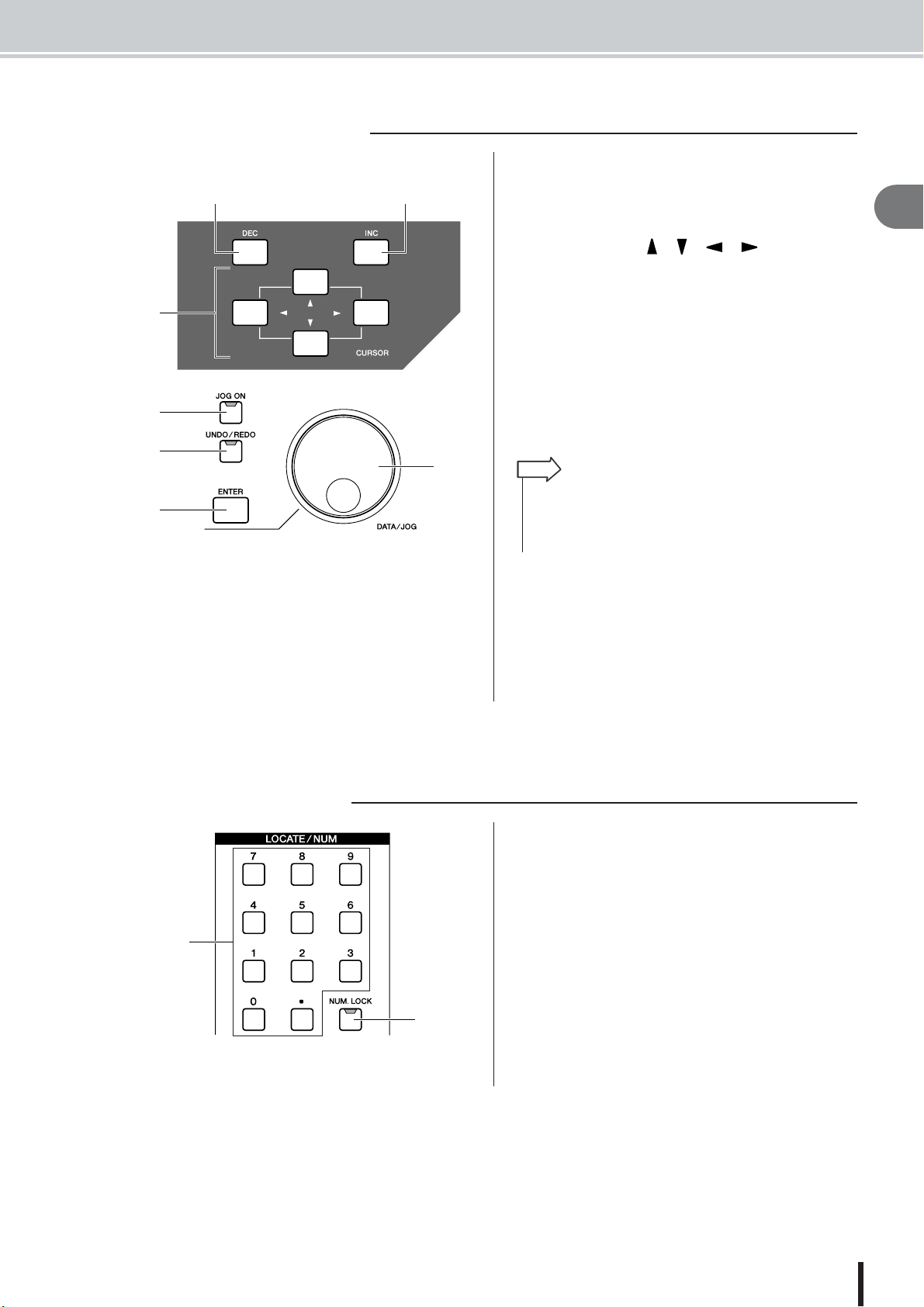
1 [INC] key
Increments (increases) the selected value by 1.
B [DEC] key
Decrements (decreases) the selected value by 1.
C [Cursor] keys ([ ]/[ ]/[ ]/[ ] keys)
These keys move the cursor (the blinking frame) around
the screen to select a specific item.
D [JOG ON] key
This key is an on/off switch for the Nudge function which
uses the [DATA/JOG] dial. When this function is on, the
key will light.
E [UNDO/REDO] key
This key cancels the results of a recording or track editing
operation (Undo), or re-executes a cancelled operation
(Redo).
HINT
2
Introducing the AW2400
F
■ Locate/Number section
1
F [ENTER] key
Use this key to operate an on-screen button, or to execute
a specific function.
G [DATA/JOG] dial
Use this dial to change the value of a parameter. If the
[JOG ON] key is on, this dial operates the Nudge function.
1 [LOCATE] keys
These keys allow you to move directly to preset “locate”
points. These keys are also used for character and number
entry.
B [NUM.LOCK] key
This key allows you to specify a destination locate point in
measures/beats.
B
AW2400 Owner’s Manual
25
Page 26
Parts of the AW2400 and what they do
■ Layer section
ABC
2
Introducing the AW2400
5D F
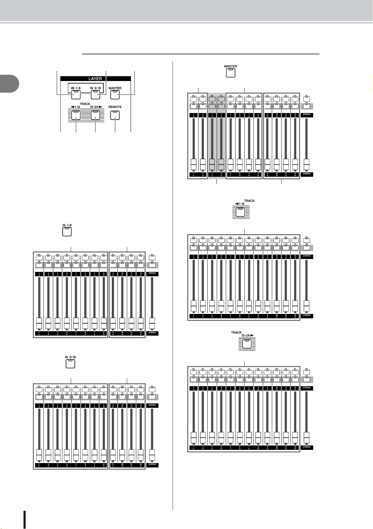
1 [IN 1-8] key
B [IN 9-16] key
C [MASTER] key
D [TRACK 1-12] key
E [TRACK 13-24] key
Select the mixing layer to be operated by the [SEL] 1–12
keys, the [ON] 1–12 keys, and faders 1–12. The mixing
layers that can be controlled when each of these keys are
engaged are as follows:
● [IN 1-8] key
Input channels 1–8 Effect Return channels 1–4
● [MASTER] key
Bus Master 1–2 AUX Send Master 1–4
No Control Effect Send Master 1–4
● [TRACK 1-12] key
Tr ack channels 1–12
● [IN 9-16] key
Input channels 9–16 Effect Return channels 1–4
AW2400 Owner’s Manual
26
● [TRACK 13-24] key
Tr ack channels 13–24
F [REMOTE] key
This key accesses the REMOTE screen, where you can
use the front panel faders and [ON] keys to control an
external MIDI device or sequencer software on your computer.
Page 27
■ Locate section
E [IN]/[OUT] keys
1C
B
E
D
7
F
I
H
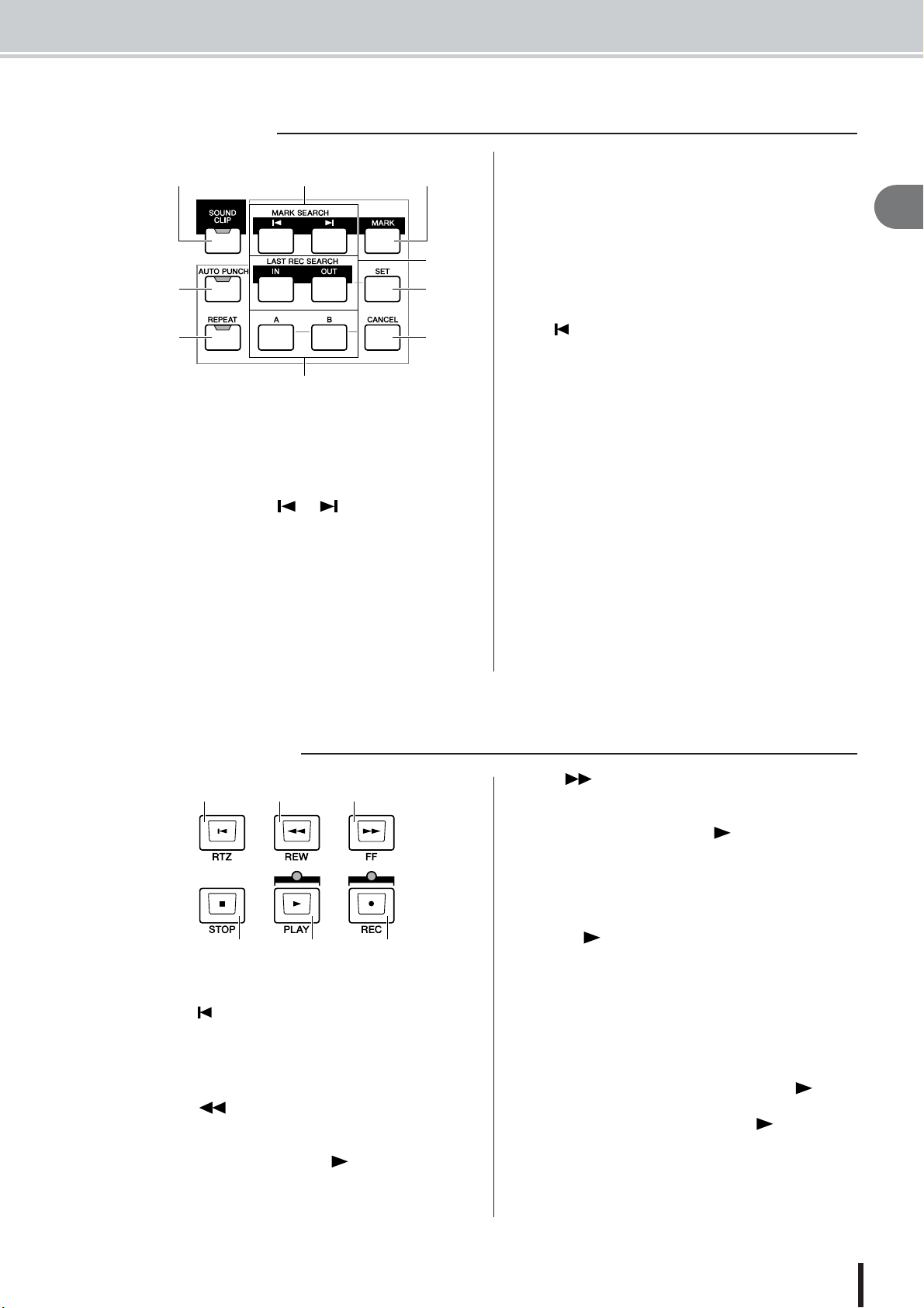
1 [SOUND CLIP] key
This key accesses the SOUND CLIP screen, where you
can record or play sound clips.
B MARK SEARCH [ ]/[ ] keys
These keys search for markers placed within the song.
C [MARK] key
This key places a marker at the current location of the
song.
D [AUTO PUNCH] key
This key switches the audio punch-in/out function on/off,
letting you automate recording.
These keys specify the points at which auto punch-in/out
recording will begin (the In point) and end (the Out point).
These keys can also be used as locate keys to move
directly to the In point or Out point.
F [SET] key
Sets the in/out or A/B points in conjunction with the [IN]/
[OUT], [A]/[B], and [LOCATE] keys. Also sets the relative zero time point when pressed simultaneously with the
RTZ [ ] key.
G [REPEAT] key
This key switches the A-B repeat function on/off, letting
you repeatedly play a specified region.
H [A]/[B] keys
These keys specify the points at which the Repeat function
will begin (point A) and end (point B). These keys can
also be used as locate keys to move directly to point A or
point B.
I [CANCEL] key
Use this key in conjunction with the [IN]/[OUT] keys, the
[A]/[B] keys or the [LOCATE] key to cancel a locater that
you registered.
Parts of the AW2400 and what they do
2
Introducing the AW2400
■ Transport section
1 B C
4 E F
1 RTZ [ ] key
This key moves directly to the absolute zero time location
or the relative zero time location. Used in conjunction
with the [SET] key, this registers the current location as
the relative zero time.
B REW [ ] key
This key rewinds the song location. Press the key repeatedly to alternate between 8x speed and 16x speed.
Press the STOP[■] key or PLAY[ ] key to stop rewind.
C FF [ ] key
This key fast-forwards the song location. Press the key
repeatedly to alternate between 8x speed and 16x speed.
Press the STOP[■] key or PLAY[ ] key to stop fast-forward.
D STOP [■] key
This key stops playback, recording, fast-forward, or
rewind. Trigger track playback will also stop.
E PLAY [ ] key
If you press this key while the recorder is stopped, playback will begin. If you press this key while holding down
the REC [●] key, recording will begin. If you press this
key during fast-forward or rewind, normal-speed playback
will begin. If you press this key during recording, recording will stop and playback will resume (“punch-out”).
F REC [●] key
If you hold down this key and press the PLAY [ ] key
while the recorder is stopped, recording will begin. If you
hold down this key and press the PLAY [ ] key during
playback, you will switch from playback to recording
(“punch-in”).
AW2400 Owner’s Manual
27
Page 28
Parts of the AW2400 and what they do
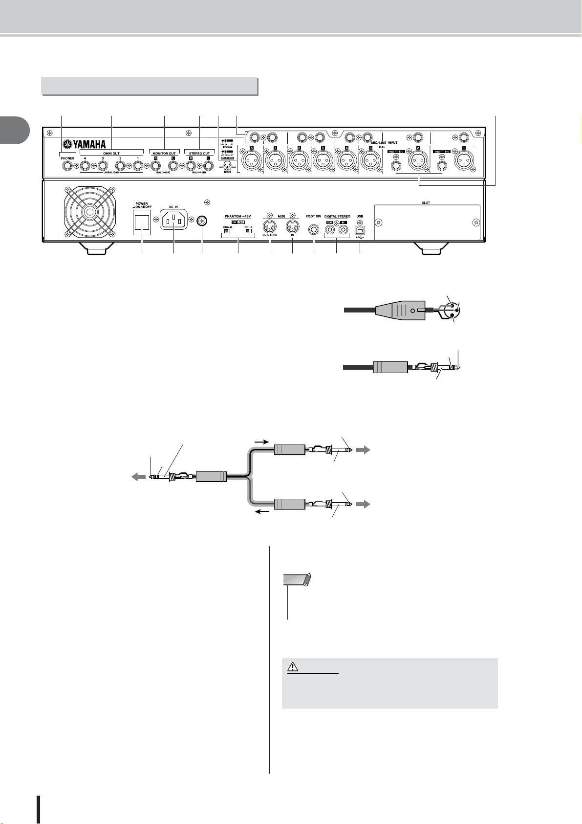
Rear panel
4G EF
B1C
2
Introducing the AW2400
H I KJ O P
1 [MIC/LINE INPUT] jacks 1–8 (XLR)
These are XLR-3-31 type balanced input jacks. Nominal input level is
from -46 dBu to +4 dBu. Connector wiring is as shown below.
B [MIC/LINE INPUT] jacks 1–8 (TRS phone)
These are TRS phone type balanced input jacks. Nominal input level is
from -46 dBu to +4 dBu. Connector wiring is as shown below.
C [INSERT I/O] jacks 1–2
These TRS phone jacks allow external signal processing gear to be inserted
into the signal received at the [MIC/LINE INPUT] jacks 1–2. Nominal
input level is 0 dBu, and the pin assignments are as follows:
L M N
Male XLR connector
1/4" TRS phone plug
Q
1 (ground)
Ring (cold)
Sleeve (ground)
3 (cold)
2 (hot)
Tip (hot)
Sleeve (ground)
OUT
IN
To the INSERT I/O
jack of the AW2400
1/4" TRS
phone plug
D [STEREO OUT] jacks
These are TRS phone type balanced output jacks that output the signals of the stereo bus. Nominal output level is
+4 dBu.
E [MONITOR OUT] jacks
These are TRS phone type balanced output jacks that output the monitor signals of the stereo bus or the solo bus.
Nominal output level is +4 dBu.
F [OMNI OUT] jacks 1–4
The unbalanced phone jacks output the signals specified in
the PATCH screen Output page. Nominal output level is 0
dBu.
G [PHONES] jack
This is a 1/4" TRS phone output jack for connecting your
headphones for monitoring. This jack always outputs the
same signal as the [MONITOR OUT] jacks.
1/4" TRS
phone plug
1/4" TRS
phone plug
Sleeve (ground)
Tip (OUT)
To the input jack of the
external processor
Sleeve (ground)
Tip (IN)
To the output jack of the
external processor
H [POWER] switch
Switches the power ON and OFF.
NOTE
• When switching the power of the AW2400 ON or OFF, always follow the “Turning the power on/off” procedures described on
page 38.
I [AC IN] connector
Connect the supplied power cord to this connector.
CAUTION
• Use only the supplied power cord for this unit. The use of an
inappropriate replacement may be a fire and electrical shock
hazard.
J Ground Screw
For maximum safety the ground screw should be properly
connected to a confirmed ground point. Proper grounding
will also ensure minimum hum, noise, and interference.
AW2400 Owner’s Manual
28
Page 29
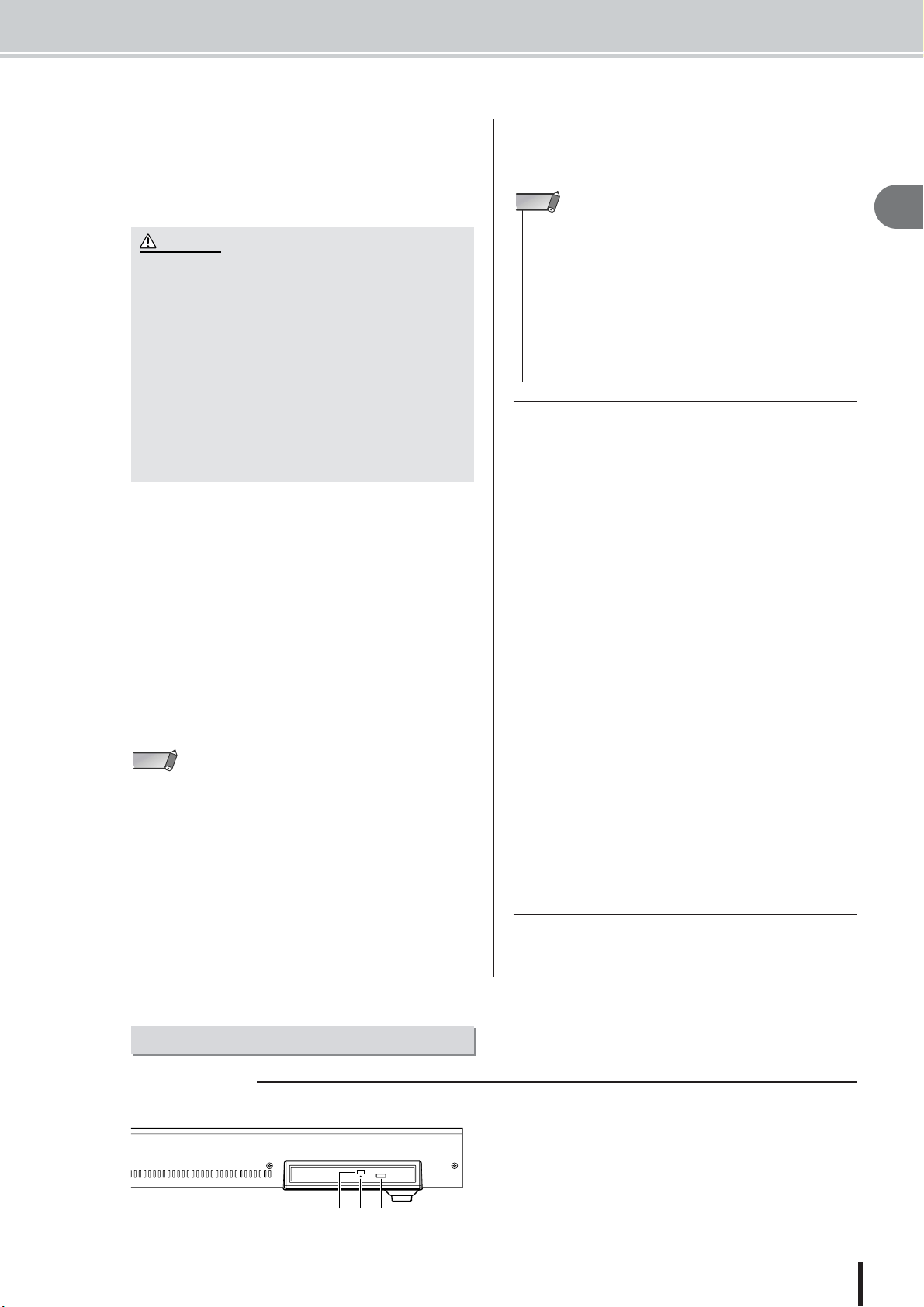
Parts of the AW2400 and what they do
CAUTION
• The USB interface cannot be directly connected to external hard
disks or CD-R/RW drives.
• The AW2400 can be connected to either a USB 2.0 or USB 1.1
interface, but data transfer will be slower if a USB 1.1 interface is
used.
• When connecting via USB 2.0 be sure to use a cable specified for
USB 2.0 use.
• The USB MIDI driver provided on the supplied CD-ROM must be
properly installed to allow MIDI message transmission and reception.
K PHANTOM +48V [CH1-4] and [CH5-8] switches
Independent phantom power switches are provided for the
XLR-type [MIC/LINE INPUT] jack groups 1 through 4
(CH1-4) and 5 through 8 (CH5-8). Turn phantom power to
the appropriate jacks ON when using one or more phantom-powered condenser microphones.
• Be sure to turn the phantom power switches off when phantom power is not required.
• Make sure that no equipment other than phantom-powered
microphones is connected to the XLR inputs of the input
group for which phantom power is turned on. Applying phantom power to devices that are not phantom-powered can
cause damage. Balanced dynamic microphones, however,
can usually be connected without adverse effect.
•To prevent speakers damage turn power amplifiers (or powered speakers) off when switching phantom power on or off.
It’s also a good idea to turn all master faders and output volume controls down to minimum. The noise generated when
phantom power is switched on or off can damage system
components and may even cause hearing damage if amplified to sufficiently high levels.
L [MIDI IN] connector
M [MIDI OUT/THRU] connector
These connectors allow MIDI messages to be exchanged
with external devices.
MIDI IN receives MIDI messages.
MIDI OUT/THRU can be internally switched to function
either as a MIDI OUT (which transmits MIDI messages
generated within the AW2400) or MIDI THRU (which retransmits messages that are received at the MIDI IN connector).
N FOOT SW jack
An optional foot switch (Yamaha FC5) can be connected
here to control transport operations such as start/stop, or to
perform punch-in/out operations.
NOTE
• The appropriate operation may not occur if you use a foot switch
other than the Yamaha FC5 (or equivalent).
O [DIGITAL STEREO IN/OUT] connectors
This RCA pin jack allows digital-audio connection to
external equipment via coaxial cable. The connector supports IEC-60958 consumer-format digital audio.
P USB connector
This connector allows the unit to be directly connected to
a USB-equipped computer via a standard USB cable
(compatible with USB 2.0). When the USB Storage mode
is selected WAV files and song files can be transferred
between the AW2400 and the computer. In the “normal”
mode the USB connection can be used for MIDI control.
The USB interface does not directly handle audio signals.
NOTE
Caution when using the USB connector
You must observe the following points when connecting the AW2400 to your computer via the USB connector. If you fail to observe these points, your
computer or the AW2400 may stop operating (“hang
up”), causing data to be corrupted or lost. If the computer or the AW2400 stops working, turn the power
off and then on again, and restart the computer.
• Before connecting the computer via the USB connector, disable the power management mode (suspend/sleep/standby/hibernate) on your computer.
• Connect the USB connector to the computer before
you power-on the AW2400.
•Execute the following before turning the power to the
AW2400 on/off, connecting/disconnecting the USB
cable, or turning the USB Storage mode on/off.
• Close all application programs.
• If the USB Storage mode is off, make sure that data is
not being transmitted from and to the AW2400.
• If the USB Storage mode is engaged, make sure that
no read or write operations are in progress.
• If the USB Storage mode is engaged, safely remove
the AW2400 from the Windows taskbar or drag the
AW2400 icons from the Macintosh desktop to the
trash after closing all AW2400 windows.
• Leave an interval of at least six seconds between
powering the AW2400 on and off, or between disconnecting and connecting the USB cable.
Q SLOT
An optional card can be installed here.
2
Introducing the AW2400
Front panel
■ CD-RW drive
1 Eject switch
This switch ejects the disc tray.
B Eject hole
This hole allows you to open the disc tray manually.
C Access indicator
123
This indicator will light while the CD inserted in the drive
is being accessed.
AW2400 Owner’s Manual
29
Page 30
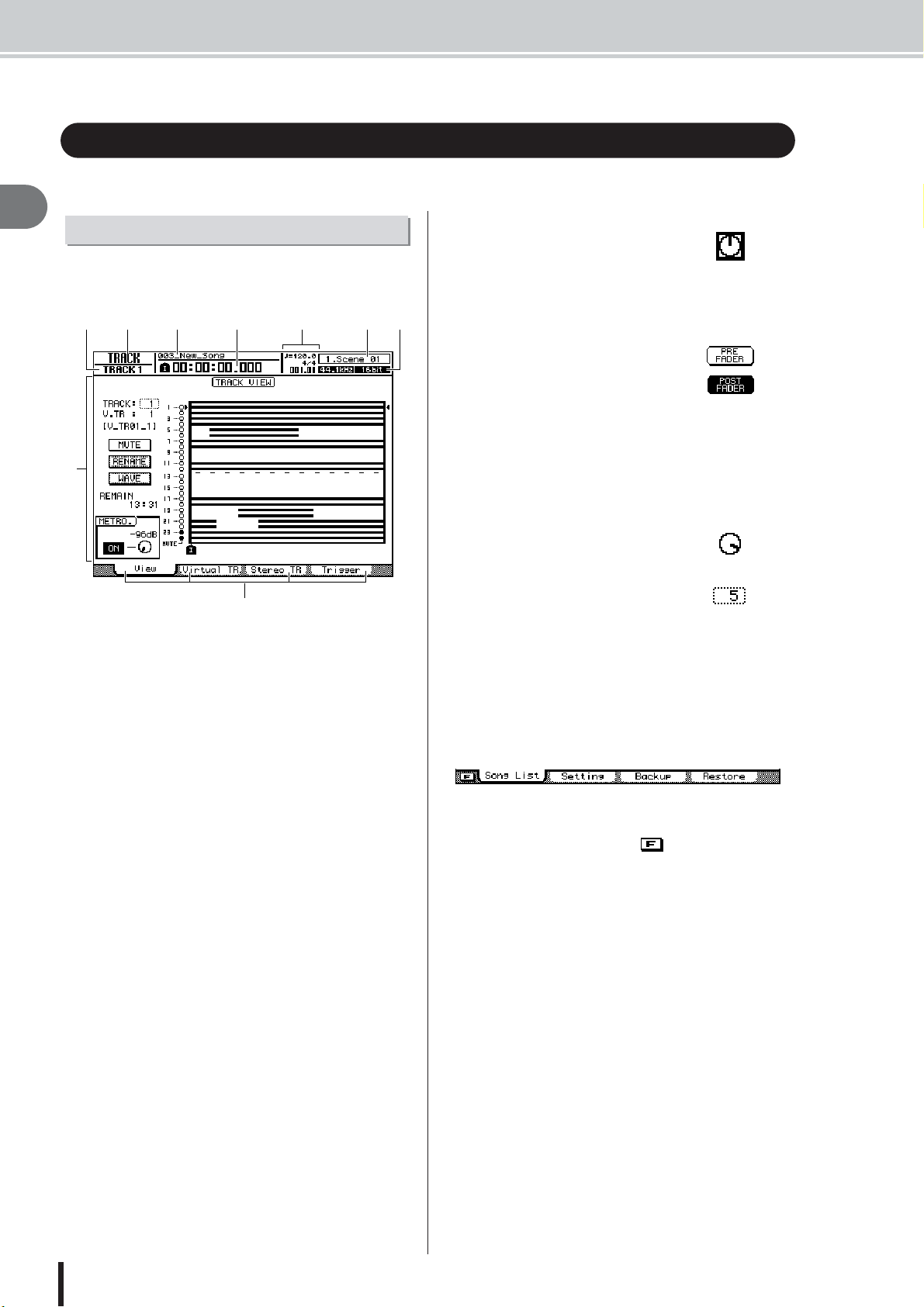
Basic operation of the AW2400
Basic operation of the AW2400
This section explains basic operation of the AW2400.
2
Introducing the AW2400
Viewing the display
The display of the AW2400 shows the following information.
B
A
C
D
H
I
1 Screen name
This is the name of the currently selected screen.
B Selected channel
This indicates the mixer channel that is selected for operation.
C Song name
The name of the currently selected song.
D Counter (left side)
This indicates the current location within the song. The
current-time display format can be selected via the SONG
screen Setting page. The choices are standard time (hours
: minutes : seconds . milliseconds) or timecode (hours :
minutes : seconds : frames . sub-frames)
E Counter (right side)
This indicates the current location within the song in measures/beats. The measures/beats are calculated according
to the tempo and time signature specified in the tempo
map for the song. The current tempo and time signature
are displayed above this value.
F Scene information
The number and name (first eight characters) of the currently selected scene.
G Sampling Rate/Quantization Bits
The sampling rate and quantization bits (bit depth) of the
currently selected song.
H Main screen
The information displayed in this area will depend on the
key/knob that was last pressed. The following types of
object are displayed in the main screen.
EFG
● Cursor
The blinking frame within the display is called the “cursor.” When an
object in the screen is enclosed by
the cursor, that object is selected for
operation.
● Buttons
Buttons in the display are used to
switch a parameter on/off, to select
one of multiple choices, or to execute
a specific function. A button that is
currently on will be displayed in
“inverse” form (black background
with white text). A button that is currently off will be displayed in normal
form (black text against a white
background).
● Knob/parameter display area
The knob/parameter display area
within the display is used to edit the
value of the corresponding parameter.
Knob
parameter
display area
Off
On
I Tabs
When a screen includes a number of pages, corresponding
tabs will appear along the bottom of the display. The tabs
are used to switch between the various pages related to the
current screen.
In some cases the tabs also become “additional function
buttons” when the [SHIFT] key is pressed. When additional functions are available an mark will appear in
the lower left corner of the display.
AW2400 Owner’s Manual
30
Page 31

Accessing a screen/page
Switching a button on/off
Editing a value in the display
Using Additional Function Buttons
Additional Function Buttons
Basic operation of the AW2400
When you want to edit an internal setting of the AW2400,
or to edit a parameter that cannot be operated by a fader or
knob on the top panel, you will need to access the desired
screen and page.
Press the key or knob for the desired
1
screen.
The keys and knobs of various sections listed below
have their own screens, and the corresponding screen
will be displayed when you press a key or knob.
• All keys in the Work Navigate section
• All keys in the Quick Navigate section
• The [METER] key in the Display section
• The [VIEW]/[DYN]/[AUX]/[EFFET]/[PAN/EQ] keys of
the Selected Channel section
• All knobs of the Selected Channel section
• All keys of the Scene/Automix/USB section
• The [REMOTE] key of the Layer section
• The [SOUND CLIP] key of the Locate section
HINT
• Press a SELECTED CHANNEL knob after pressing the
SELECTED CHANNEL [DYN], [AUX], [EFFECT, or [PAN/EQ]
key to access the related display screen.
• When you switch screens, the page that was last used in that
screen will be displayed.
Use the [F1]–[F4] keys to select different
2
pages within a screen.
The [F1]–[F4] keys correspond to the tabs as follows.
Here’s how to switch a button in the screen on/off.
Use the [CURSOR] keys to
1
move the cursor to the
desired button in the screen.
Press the [ENTER] key.
2
The button will be switched on/off.
If you move the cursor to a button
that executes a specific function and
then press the [ENTER] key, that
function will be executed.
Here’s how to edit the value of a knob or parameter shown
in the display.
Use the [CURSOR] keys to
1
move the cursor to the
desired knob or parameter
value.
Turn the [DATA/JOG] dial or
2
press the [INC]/[DEC] keys to
edit the value.
2
Introducing the AW2400
[F1] key [F2] key [F3] key [F4] key
HINT
•You can access the pages in sequence by repeatedly pressing the key referred to in step 1, above.
When an mark appears in the lower left corner of the
display the tabs shown along the bottom of the display can
be switched to provide additional functions.
Press the [SHIFT] key when any screen with
1
an mark in the lower left corner is
showing.
The additional function buttons will appear in place of
the tabs along the bottom of the display while the
[SHIFT] key is held.
While holding the [SHIFT] key press the
2
[F1]–[F4] button to execute the corresponding function.
AW2400 Owner’s Manual
31
Page 32

Basic operation of the AW2400
Entering text
When you create a new song or save a scene memory or
library setting, a popup window will appear allowing you
to assign a name for the song or setting.
2
Introducing the AW2400
C
E
D
This popup window contains the following items and
functions.
1 Text input box
This box lets you input characters, numbers, and symbols.
The character currently selected for editing is shown
inverted (white on black). When you save the data for the
first time, the box will contain a default name. The
inverted highlight can be moved as required by using the
[DATA/JOG] dial.
B CANCEL button
If you move the cursor to this button and press the
[ENTER] key, you will return to the previous screen without changing the name.
C OK button
If you move the cursor to this button and press the
[ENTER] key, the scene/library will be saved or the new
song will be created.
D SHIFT LOCK button
Switches between upper or lower case characters, or the
type of symbol to be entered at the current edit position in
the text entry box.
E / buttons
Move the inverted edit position left or right.
HINT
• The inverted edit position can also be moved left or right by using
F INS button
Inserts an under-bar space (“_”) at the inverted edit position. All characters following the insert are moved to the
right. Pressing the [INC] key has the same effect as the
INS button.
B
A
the [DATA/JOG] dial.
H I
G
F
G DEL button
Deletes the character at the inverted edit position. All
characters following the delete are moved to the left.
Pressing the [DEC] key has the same effect as the DEL
button.
H Text palette
This displays the characters, numbers, and symbols that
can be input in the text input box. To enter a new character
at the inverted edit position, move the cursor to the desired
character in the text palette and press the [ENTER] key.
The available characters and symbols are as follows:
A–Z a–z SPC(space) , . ! " # & / * + - < > : ;
I Number Palette
Selects the number to be entered in the text entry box. To
enter a number at the inverted edit position, move the cursor to the desired number in the palette and press the
[ENTER] key.
By repeatedly pressing the [ENTER] key you can sequentially select and enter the characters displayed for each
number button. For example, if you move the cursor to “1”
in the number palette and then repeatedly press the
[ENTER] key you will sequentially select the following
number/characters for entry: 1 → P → Q → R → S → p →
q → r → s → 1, and then the cycle repeats.
■ Using the [LOCATE] Keys
To Enter Characters & Numbers
The [LOCATE] keys in the LOCATE/NUMBER section
can be used to enter characters and numbers in the same
way as the number palette. Repeatedly press the appropriate [LOCATE] key (0–9) to select the required number or
character.
The numbers and characters selected by each key are as
follows:
[LOCATE]
Key Number
00
11 → P → Q → R → S → p → q → r → s
22 → T → U → V → t → u → v
33 → W → X → Y → Z → w → x → y → z
44 → G → H → I → g → h → i
55 → J → K → L → j → k → l
66 → M → N → O → m → n → o
77
88 → A → B → C → a → b → c
99 → D → E → F → d → e → f
Selected Number/Character
(Arrows indicate selection sequence)
NOTE
•To add characters to a name that has less than the maximum
number of characters, move the cursor to the INS button and
press the [ENTER] key to insert “_”, then change the name as
required.
AW2400 Owner’s Manual
32
Page 33

Switching mixing layers affects the functions of [ON] keys 1–12, [SEL]
Switching Mixing Layers
Layer Section
Currently selected channel.
keys 1–12, and faders 1–12, allowing efficient control in a variety of signalrouting configurations. Remote control of external equipment is also possible.
Different mixing layers are selected via the keys in the LAYER section. The
key corresponding to the currently selected mixing layer will be lit.
The mixer section controls correspond to the various mixing layers as follows:
Basic operation of the AW2400
2
LAYER
Section Key
[IN 1-8] Input Channels 1–8 Effect Return Channels 1–4
[IN 9-16] Input Channels 9–16 Effect Return Channels 1–4
[MASTER]
[TRACK 1-12] Tr ack Channels 1–12
[TRACK 13-24] Tr ack Channels 13–24
[REMOTE] *
1 2 3 4 5 6 7 8 9 10 11 12 STEREO
Bus Masters
1–2
No Control AUX Send Masters 1–4 Effect Send Masters 1–4
Fader Section
* Operation depends on settings. Refer to page 204 for details.
For example, if the LAYER section [IN 1-8] key is engaged and the [SEL] 1
key is pressed, input channel 1 will be selected. If the LAYER section
[TRACK 1-12] is then engaged and the same [SEL] 1 key is pressed, track
channel 1 will be selected.
HINT
• The [STEREO SEL] key, [STEREO ON] key, and [STEREO] fader always control the
stereo output channel. These controls are not affected by layer switching.
Using the Selected Channel section
You can use the knobs and keys of the Selected Channel section to directly
operate the mix parameters (EQ, dynamics, pan, etc.) of the currently
selected channel.
Introducing the AW2400
Stereo Output
Channel Control
Use the [SEL] keys or [STEREO SEL] key to select the
1
channel that you want to operate.
The currently selected channel is indicated in the upper left of the
screen. The channels correspond to each key as follows.
• [SEL] keys 1–12............ Input channels 1–16, Track channels 1–24,
• [STEREO SEL] key....... Stereo output channel
HINT
• The channels to be selected by [SEL] keys 1–12 are switched via the LAYER
section.
Effect Return channels 1–4
AW2400 Owner’s Manual
33
Page 34

Basic operation of the AW2400
Press the SELECTED CHANNEL section [DYN], [AUX],
2
[EFFECT], or [PAN/EQ] key so that its indicator light,
according to the parameters you want to control.
With the default settings the screen corresponding to the pressed key will
2
appear automatically. The display will not change if the UTILITY screen
Preference page AUTO DISPLAY button is set to OFF (→ p. 211).
Introducing the AW2400
The parameters that can be controlled by the SELECTED CHANNEL
knobs are as follows:
Selected Key (Lit) Knob 1 Knob 2 Knob 3 Knob 4
[DYN]
[AUX]
[EFFECT]
[PAN/EQ] Pa n Equalizer Q. Equalizer frequency. Equalizer gain.
Multiple compressor parameters, or the last parameter
operated, depending on the
control status.
Send level from channel to
AUX 1.
Send level from channel to
EFFECT 1.
Compressor threshold. Compressor ratio. Compressor gain.
Send level from channel to
AUX 2.
Send level from channel to
EFFECT 2.
Send level from channel to
AUX 3.
Send level from channel to
EFFECT 3.
Send level from channel to
AUX 4.
Send level from channel to
EFFECT 4.
HINT
• After selecting a channel, press the SELECTED CHANNEL [VIEW] key to call
the CH VIEW screen where you can edit the channel signal routing and all of the
channel parameters. Refer to page 105 for details on the CH VIEW screen.
NOTE
• The parameter controlled by SELECTED CHANNEL knob 1 when the [DYN] key
is engaged depends on the current operating status (
• If you operate SELECTED CHANNEL knob 1 immediately after recalling a setup
from the compressor preset library, multiple compressor parameters will be
adjusted simultaneously, changing the overall effect of the compressor (the type
of change depends on the recalled preset library setup).
• When individual compressor parameters for a channel have been adjusted via
the DYNAMICS screen, the last parameter adjusted is assigned to SELECTED
CHANNEL knob 1 (the last-adjusted parameter is individually retained for each
channel).
Rotate SELECTED CHANNEL knobs 1–4 to adjust the cor-
3
→
p. 153).
responding parameters as required.
If the UTILITY screen Preference page AUTO DISPLAY button is set to
OFF, a popup window showing the corresponding parameter name and
the value will appear while the knob is being operated.
AW2400 Owner’s Manual
34
Page 35

If you want more precise editing control over the parame-
4
ter selected in step 2, above, press the corresponding
SELECTED CHANNEL knob (1–4) to call up the screen
containing the related parameters.
Basic operation of the AW2400
Selected Key (Lit) Knob 1 Knob 2 Knob 3 Knob 4
[DYN] DYNAMICS Screen DYNAMICS Screen DYNAMICS Screen DYNAMICS Screen
[AUX] AUX1 Screen AUX2 Screen AUX3 Screen AUX4 Screen
[EFFECT] EFFECT1 Screen EFFECT2 Screen EFFECT3 Screen EFFECT4 Screen
[PAN/EQ] PAN/EQ Screen PAN/EQ Screen PAN/EQ Screen PAN/EQ Screen
NOTE
• The display will not change if the SELECTED CHANNEL knob is simply rotated.
To switch screens the knobs must be pressed.
• Other gate functions can be accessed via the DYNAMICS screen, but only
pages and parameters related to compressor operation can be accessed via the
SELECTED CHANNEL knobs.
Move the cursor in the screen to the desired parameter,
5
and use the [DATA/JOG] dial or the [ENTER] key to operate the parameter.
2
Introducing the AW2400
AW2400 Owner’s Manual
35
Page 36

2
Introducing the AW2400
AW2400 Owner’s Manual
36
Page 37

Chapter 3
Connection and Setup
This chapter will describe the AW2400 setup process from connection to
instruments and other external equipment up to getting sound from a monitor
system.
Connection
3
The following connection diagram shows a typical AW2400 setup. Connect your microphones,
instruments, and other external gear as shown in the diagram.
DAW system Monitor system
Audio interface
[MONITOR OUT] jacks
[PHONES] jack
Headphones
[OMNI OUT] jacks
Effect processor
HDR
I/O card
[DIGITAL STEREO
IN/OUT] connectors
I/O SLOT
[USB] connector
Connection and Setup
Effect processor
[INSERT I/O] jacks
[MIC/LINE INPUT] jacks
Microphones
Rhythm machine
Synthesizer
MUSIC PRODUCTION SYNTHESIZER
AW2400 Owner’s Manual
37
Page 38

Turning the power on/off
Turning the power on/off
Follow the procedure outlined below when turning the AW2400 power ON and OFF. Failure to follow this procedure can result in damage to the internal hard disk or your external monitor system.
Call the SONG screen Song List page by
■ Turning the power on
3
In a system that includes the AW2400, turn the power to
Connection and Setup
each device on in the following order.
1 External devices such as audio sources and effect
processors connected to the input/output jacks of
the AW2400
B The AW2400 itself
C The monitor system connected to the AW2400’s out-
put jacks
CAUTION
• Before you turn on the power, make sure that the power cord
is securely connected to the AW2400 and to the AC outlet. If
the power is disconnected while the AW2400 is in use, the
AW2400 or it’s internal hard disk may be damaged.
1
pressing the Work Navigate section [SONG]
key located in the upper left of the top panel
as many times as necessary.
When you turn on the AW2400 power a startup screen will
appear briefly, and then the following screen will appear.
■ Turning the power off (shut down)
In a system that includes the AW2400, turn the power to
each device off in the following order.
1 The monitor system connected to the AW2400’s out-
put jacks
B The AW2400 itself
C External devices such as audio sources and effect
processors connected to the input/output jacks of
the AW2400
When turning the AW2400 power off, be sure to perform
the following “shut-down” procedure.
SHUTDOWN button
Using the CURSOR keys located in the
2
upper right of the top panel, move the cursor (the blinking area in the screen) to the
SHUTDOWN button.
Press the [ENTER] key located in the mid-
3
dle right of the top panel.
A popup window will ask you whether you want to
save the current song.
Move the cursor to the YES button if you
4
want to save the current song, or to the NO
button if you do not want to save it. Then
press the [ENTER] key.
When the “Now safe to turn off...” message
5
appears, turn off the [POWER] switch
located on the rear panel.
AW2400 Owner’s Manual
38
IMPORTANT
• If you turn off the AW2400 power without performing the
above shutdown procedure, not only will any unsaved
changes be lost, but you also risk damaging the data on
the hard disk, and damaging or drastically shortening the
lifespan of the hard disk itself as well as the internal CDRW drive. Please use caution.
Page 39

Adjusting the input level
1/4" phone ↔ phone cable
Synthesizer/
rhythm machine
[MIC/LINE INPUT] jacks
1–8 (TRS phone)
• The XLR and TRS phone jacks for the same channel cannot
be used simultaneously. Connecting sources to both inputs
on the same channel at the same time can result in interference and a severely degraded input signal.
• The [GAIN] knobs adjust the gain (sensitivity) of the analog
input stage. In order to make recordings with the greatest
dynamic range and minimum noise, set the [GAIN] knob as
high as possible without causing clipping.
Adjusting the input level
Here’s the basic procedure for setting up an input channel to which a microphone or instrument
is connected via [MIC/LINE INPUT] jack 1–8, and adjusting the input level while monitoring the
signal via the stereo bus.
Turn down the [GAIN] knob for the [MIC/
1
LINE INPUT] jack to which your instrument/
mic is connected. Also lower the [STEREO]
fader to the – ∞ position.
Connect a microphone or instrument to the
2
appropriate [MIC/LINE INPUT] jack.
[MIC/LINE INPUT] jacks 1–8 can be used with the
following sources.
● [MIC/LINE INPUT (XLR)] jacks 1–8
These are XLR-type balanced input jacks. Use a male
XLR ↔ female XLR cable to connect your microphone, direct box, or a guitar/bass preamp that has a
balanced output jack.
Balanced cable
(male XLR ↔ female XLR)
[MIC/LINE INPUT]
jacks 1–8 (XLR)
HINT
• When using condenser microphones or direct boxes that
require phantom power, turn on the rear-panel [CH1-4] switch
which supplies phantom power to [MIC/LINE INPUT] jacks 1–
4, and/or the [CH5-8] switch which supplies phantom power to
[MIC/LINE INPUT] jacks 5–8 as required.
Mic
Preamp or effect processor with balanced output
Direct box
Electric
guitar/bass
These connectors will also accept unbalanced output
from instruments such as synthesizers or rhythm
machines via standard mono 1/4" phone ↔ 1/4" phone
jack cables.
NOTE
While playing the connected
3
instrument or supplying
appropriate sound to the
connected microphone,
rotate the corresponding
[GAIN] knob clockwise to
adjust the input sensitivity
so that the [PEAK] indicator
lights only occasionally.
HINT
3
Connection and Setup
● [MIC/LINE INPUT (TRS phone)] jacks 1–8
These are TRS-type balanced input jacks. Use a 1/4"
TRS phone ↔ female XLR cable to connect your
microphone, direct box, or a guitar/bass preamp that
has a balanced output jack.
1/4" TRS phone ↔
female XLR cable
[MIC/LINE INPUT] jacks
1–8 (TRS phone)
Mic
Preamp or effect processor with balanced output
Direct box
Electric
guitar/bass
AW2400 Owner’s Manual
39
Page 40

Adjusting the input level
Call the METER screen Input/RTN page by
4
either pressing the Display section
[METER] key as many times as necessary,
or by pressing the [F1] key after pressing
the [METER] key.
The input channel input levels are displayed at the top
of this screen.
3
Connection and Setup
Input channel input level display
HINT
• If the level meter goes into the “OVER” region, check that the
corresponding input fader is set to 0dB and reduce the level of
the [GAIN] knob.
While playing the connected instrument,
8
raise the [STEREO] fader to the 0 dB position.
With the initial default settings the
input channels are patched to the
AW2400’s stereo bus. Signals sent to
the stereo bus are output via the
[STEREO OUT], [MONITOR
OUT], and [OMNI OUT] jacks after
being adjusted by the [STEREO]
fader. When the [STEREO] fader is
raised the level of the stereo bus signal will be displayed on the Display
section stereo meter. You can now
rotate the [MONITOR] or
[PHONES] knob clockwise to hear
sound from your monitor system or
headphones.
Move the cursor to the POST FADER button
5
in the lower area of the screen and press
the [ENTER] key.
When the POST FADER button is turned on the signal
levels immediately following the fader are displayed
on the meters.
Press the Layer section [IN 1-8] so that it’s
6
indicator lights to switch to the IN 1-8 mixing layer.
You can now use [ON] keys 1–8, [SEL] keys 1–8, and
faders 1–8 to operate input channels 1–8.
HINT
• With the initial default settings the signals from [MIC/LINE
INPUT] jacks 1–8 are assigned to the corresponding input
channels 1–8. You can change these settings as required.
Refer to “Direct recording and Mixed recording” on page 49
for details.
Make sure that the [ON] key for the channel
7
receiving the microphone or instrument
signal is engaged and its indicator is lit,
then raise the channel fader to the 0dB
position.
If you play the instrument or
play into the microphone you
should see the level meter on
the display respond accordingly, but you won’t hear any
output from your monitor system yet because the [STEREO] fader is still all the way
down.
NOTE
• If the stereo meter does not respond even though the input
channel level meter is showing the presence of a signal when
the [STEREO] fader is raised, check that the input channel is
patched to the stereo bus (
That completes the initial setup and level adjustment procedure required to begin recording on the AW2400. Levels
will have to be readjusted whenever you change the
microphone or instrument input connections or change the
output level of an instrument (level changes will often
occur when you change synth patches).
By using the [GAIN] knob to raise the level as far as possible without allowing distortion to occur, you can ensure
that the input signal is converted into digital form with the
highest possible quality before it is input to the mixer section.
→
p. 105).
AW2400 Owner’s Manual
40
Page 41

Chapter 4
• If you select NO, any changes that you made to the current
song since you last saved it will be lost.
Listening to the demo song
When the AW2400 is shipped from the factory, its hard disk contains a demo song. This chapter
explains how to load and play back the demo song.
Loading the demo song
Here’s how to load the demo song from the hard disk.
Press the Work Navigate section [SONG]
1
key.
The SONG screen will appear, where you can save or
load songs.
Call the Song List page by either pressing
2
the [SONG] key as many times as necessary, or by pressing the [F1] key after
pressing the [SONG] key.
In this page, you can select a song on the hard disk,
and load or delete it.
B
A
3
4
4
Move the cursor to the song list, and then
use the [DATA/JOG] dial or [INC]/[DEC] keys
to select the song “The_Only_One.”
Listening to the demo song
Move the cursor to the LOAD button in the
screen, and press the [ENTER] key.
A popup window like the following will appear. This
window asks you whether you want to save the current
song.
1 Song list
This area lists the songs that are saved on the hard
disk. The line enclosed by the dotted frame in the center of the list indicates the song that is selected for
operations. The highlighted line indicates the song that
is currently loaded into the AW2400. (This is called
the “current song.”)
NOTE
• Each row of the list will display the song name, data size, bit
depth (16/24 bit), and sampling rate (44.1/48 kHz).
B LOAD button
Loads the selected song.
Move the cursor to either YES (save the cur-
5
rent song) or NO (don’t save the current
song), and press the [ENTER] key.
The song data will be loaded, and “The_Only_One”
will become the current song.
NOTE
“You’re the Only One”
© Timothy Akers
AW2400 Owner’s Manual
41
Page 42

Playing the demo song
Playing the demo song
Here’s how to play back the demo song you loaded, and adjust the monitor level.
Make sure that the AW2400’s [MONITOR]
1
knob, [PHONES] knob, and the volume of
your monitor system are turned down.
Press the PLAY [ ] key.
2
4
Listening to the demo song
The demo song will begin playing.
To adjust the monitor level appropriately,
3
use the AW2400’s [MONITOR] knob,
[PHONES] knob and the volume control of
your monitor system.
HINT
• The demo song uses the Scene function to switch the settings
of the mixer. This means that playback will occur using the
pre-specified balance — you do not need to operate the faders.
To stop the song, press the STOP [■] key.
4
AW2400 Owner’s Manual
42
Page 43

Chapter 5
Recording to a sound clip
The AW2400 has a Sound Clip function that lets you record and play back
independently of the recorder section. You can use a sound clip to quickly
record and play back your performances on an audio source connected to
the AW2400. This is an ideal way to capture ideas for a song or arrangement,
or to record a simple accompaniment for practicing a part.
This chapter explains how sound clips can be recorded using an instrument
or microphone connected to an input jack.
Recording a sound clip
The post-fader signal of the stereo output channel can be recorded directly to a sound clip. For
playback, the signal will be sent to the stereo output channel immediately before the stereo fader
(EQ and dynamics cannot be applied to sound clip playback).
5
Recording to a sound clip
● Signal flow when using a sound clip
[MIC/LINE INPUT]
jacks
Input
channels
Metronome
Sound
clip
Stereo
output
channel
Stereo bus
Mixer section
AW2400 Owner’s Manual
43
Page 44

Recording a sound clip
Connect the required instrument and/or
1
microphone input sources and set up the
levels as described in “Connection and
Setup” on page 37.
Press the Locate section [SOUND CLIP]
2
key.
The SOUND CLIP screen will appear, where you can
record and play sound clips.
5
Recording to a sound clip
C
D
A
B
EFG
To use the metronome, move the cursor to
3
the metronome button and press the
[ENTER] key.
To change the tempo of the metronome,
4
move the cursor to the tempo value and
turn the [DATA/JOG] dial.
NOTE
• The time signature of the metronome is determined by the
tempo map setting that was active prior to accessing the
SOUND CLIP screen. Please be aware that the setting cannot be edited from this screen. (For details on tempo map settings
→
p. 62)
Hold down the Transport section REC [●]
5
key and press the PLAY [ ] key.
The metronome will start and the counter display will
advance. The SOUND CLIP screen counter always
starts from 0 and indicates the current time in minutes/
seconds/milliseconds. This counter is separate from
the normal song counter.
Play the part to be recorded in time with the
6
metronome.
1 Tempo
Sets the tempo of the metronome used when recording
sound clips.
B Time signature
Shows the time signature of the metronome.
C Metronome button
Switches the metronome on/off.
D Metronome knob
Adjusts the volume of the metronome. The value
above the knob shows the current setting in dB.
E START button
Specifies the current location as the start point of the
sound clip (the location at which playback will begin).
The current location is shown in minutes/seconds/milliseconds to the left.
F END button
Specifies the current location as the end point of the
sound clip (the location at which playback will end).
The current location is shown in minutes/seconds/milliseconds to the left.
G CLIP button
Turn this button on to enable the START button (
and END button (
F) settings.
E)
HINT
• The metronome sound will not be recorded. If necessary, you
can move the cursor to the metronome knob and turn the
[DATA/JOG] dial to adjust the volume of the metronome
sound.
• The knobs/keys of the selected channel are active even while
the SOUND CLIP screen is showing. If necessary, you can
apply EQ and dynamics processing to the signal being
recorded.
Press the STOP [■] key to stop recording.
7
and symbols on the display indicate the start and
end point.
HINT
• With the default AW2400 settings a maximum of 30 seconds
can be recorded to a sound clip. If you continue recording for
longer than 30 seconds, the last 30 seconds recorded will be
retained (the counter display during recording will continue to
advance).
•You can specify up to 180 seconds as the maximum length
that can be recorded in a sound clip. You are free to make this
setting before creating a new song, but this cannot be
changed once the song has been created. (
→
p. 47)
NOTE
• The Recorder section cannot be used for recording and playback while the SOUND CLIP screen is showing.
AW2400 Owner’s Manual
44
Page 45

Playing a sound clip
• The START button, END button, and CLIP button are disabled
while the sound clip is playing.
• The data region between the specified Start and End points
can be copied to an audio track of the Recorder section by
using the EDIT screen COPY command (
→
p. 139).
• When you record a new sound clip, the previous recorded
sound clip will be erased. Please be aware that the Undo
function cannot be used to recover a deleted sound clip. Even
if you save the song immediately prior to recording a new
sound clip, the previous sound clip will not be restored if you
recall the song data.
• The recorded contents of the sound clip are stored individually for each song.
Playing a sound clip
Press the PLAY [ ] key to hear the
1
recorded sound clip.
The sound clip will play repeatedly from the start
point to the end point. To stop playback press the
STOP [■] key. If you record again, the previous data
will be overwritten.
The Transport section keys will have the following
functions while the SOUND CLIP screen is showing.
Key Function
RTZ [ ] key
REW [ ] key
FF [ ] key
STOP [■] key
PLAY [ ] key
REC [●] key
HINT
•You will not hear the metronome while a sound clip is playing,
but you can still monitor the signals of input channels 1–16.
Returns to the location at which you
began recording. If the CLIP button is on,
this returns to the Start point.
Rewinds the current location toward the
beginning. You will stop when you reach
the location at which you began recording
or the Start point.
Fast-forwards the current location. You will
stop when you reach the location at which
you stopped recording or the End point.
Stops playback, recording, rewind, or fastforward.
Starts playback. Pressing this key during
playback does nothing.
If you hold down this key while stopped
and press the PLAY [ ] key, recording
will begin. Pressing this key during playback does nothing.
Stop playback, move the cursor to the CLIP
3
button, and press the [ENTER] key.
The CLIP button will be engaged, and the specified
Start point and End point will be enabled.
NOTE
HINT
To exit the SOUND CLIP screen, press the
4
Work Navigate section (except for [PATCH]
key) or Quick Navigate section keys,
[AUTOMIX] key, [USB] key, [REMOTE] key,
or [SOUND CLIP] key.
A popup window will ask you for confirmation. Move
the cursor to the OK button to exit the SOUND CLIP
screen, or to the CANCEL button to cancel, then press
the [ENTER] key.
You can return to the SOUND CLIP screen by pressing the [SOUND CLIP] key even after having exited
the screen, then play back the previously recorded
content or record a new performance.
NOTE
5
Recording to a sound clip
The playback region of a sound clip can be
2
changed by specifying new Start and End
points as described below.
● Specifying the Start point
Stop at the location that you want to specify as the
Start point, move the cursor to the START button, and
press the [ENTER] key.
The START button will be engaged and the current
location will be registered as the Start point.
● Specifying the End point
Stop at the location that you want to specify as the End
point, move the cursor to the END button, and press
the [ENTER] key.
The END button will be engaged and the current location will be registered as the End point.
HINT
AW2400 Owner’s Manual
45
Page 46

5
Recording to a sound clip
AW2400 Owner’s Manual
46
Page 47

Chapter 6
• Songs recorded with a sampling frequency of 48 kHz cannot
be written to an audio CD.
Track recording
This chapter explains how to record the audio signal from an instrument or
microphone connected to the AW2400 to the tracks of a song.
Creating a new song
Before you can begin recording on the AW2400 you need to create a new song.
HINT
• When you start up the AW2400 for the first time, an empty song will be loaded automatically.
If you use this automatically-loaded song, the procedure described here is not necessary.
Call the SONG screen Song List page by
1
either pressing the Work Navigate section
[SONG] key as many times as necessary, or
by pressing the [F1] key after pressing the
[SONG] key.
The currently selected song in the Song List will be
highlighted (inverted).
NEW button
Move the cursor to the NEW button and
2
press the [ENTER] key.
A popup window will ask you whether you want to
save the current song.
Move the cursor to YES (to save the current
3
song) or NO (if you don’t want to save the
current song) and press the [ENTER] key.
A popup window containing the various settings for
the new song will appear.
The following settings can be made via this popup
window.
•Fs............................... The sample rate of the new
song can be set to either
44.1 kHz or 48 kHz.
• Recbit ........................ The bit depth of the new
song can be set to either 16
or 24 bits.
• Sound Clip Time ....... The sound clip record time
can be set to between 30–
180 seconds.
NOTE
6
Tr ack recording
AW2400 Owner’s Manual
47
Page 48

Creating a new song
4
6
Tr ack recording
When each parameter has been set as
required, move the cursor to the OK button
and press the [ENTER] key.
Next, a popup window will appear allowing you to
specify settings that will be carried over from the current song.
The following items are available:
• SCENE button............Scene memories
• TEMPO button...........Tempo map
• LIBRARY button........EQ, dynamics, effects, and
channel libraries
For example, if you have saved effect settings in a
library for the current song and would like to use these
settings for the new song as well, you would turn on
the LIBRARY button.
Enter a name for the song (for details on
6
name entry refer to page 32).
NOTE
•A new song cannot be given the same name as an existing
song.
• The song name can also be edited later (
To create the new song, move the cursor to
7
the OK button and press the [ENTER] key.
A new song will be created, and you will return to the
SONG screen Song List page.
If you move the cursor to the CANCEL button
(instead of the OK button) and press the [ENTER] key,
you will return to the SONG screen Song List page
without creating a new song.
→
p. 169).
Select the buttons of the items you want to
5
carry over from the current song, move the
cursor to the OK button, and press the
[ENTER] key.
The NAME EDIT popup window will appear, allowing you to enter a name for the song.
AW2400 Owner’s Manual
48
Page 49

Direct recording and Mixed recording
■ Direct recording
Direct recording and Mixed recording
Instruments and/or microphones connected to the AW2400 can be recorded to tracks in one of
the following two ways.
With this method only one input channel is assigned to each recorder track. Although
direct recording requires the same number of tracks as the number of input channels
you use, it has the advantage that you will be free to adjust the volume, pan (stereo position), and EQ of each individual instrument after it has been recorded.
6
Tr ac k 1
Tr ac k 2
Tr ac k 3
Tr ac k 4
Tr ac k 5
[MIC/LINE INPUT]
jacks
Input
channels
Tr ack recording
Stereo
output
channel
Mixer section
Recorder section
AW2400 Owner’s Manual
49
Page 50

Direct recording and Mixed recording
■ Mixed recording
With this method, you can send multiple input channels to Bus 1 or Bus 2, and assign
the mixed signal to one through four tracks. Mixed recording requires fewer tracks, but
you will need to decide on the final volume, pan, and tone of each instrument at the time
of recording (you will not be able to adjust these parameters independently after recording.)
6
Tr ack recording
Tr ac k 1
Tr ac k 2
Tr ac k 3
Tr ac k 4
Tr ac k 5
Tr ac k 6
[MIC/LINE INPUT]
jacks
Input
channels
Stereo
output
channel
Bus 1
Bus 2
Recorder section
NOTE
• The way in which you assign the input signals to tracks will depend on the
method you choose.
AW2400 Owner’s Manual
50
Mixer section
Page 51

Assigning input signals to tracks
lit
(Direct recording)
This section describes the patching procedure to assign
instruments and/or microphones connected to [MIC/LINE
INPUT] jacks 1–8 to independent tracks for direct recording.
HINT
• See page 99 for more details on patching for direct recording.
Lower the [STEREO] fader to the – ∞ posi-
1
tion.
Referring to “Connection and Setup” on
2
page 37, connect your instruments and/or
microphones and set up the input levels.
Call the RECORD screen Direct page by
3
either pressing the Quick Navigate section
[RECORD] key as many times as necessary,
or by pressing the [F1] key after pressing
the [RECORD] key.
Input channel signals can be directly patched to the
recorder’s tracks via the RECORD screen Direct page.
When this page is called the [INPUT SEL] keys in the
upper area of the top panel will flash red.
Input channels
Input select
Direct recording and Mixed recording
Check that “AD1–8” appears in the input
4
select field on the left side of the page.
Input channels 1–8 or 9–16 can be selected as the
input source via the input select field. When “AD1–8”
is showing the AW2400’s AD inputs ([MIC/LINE
INPUT] jacks 1–8) are selected as the input source. If
a different input source is selected move the cursor to
the input select field and use the [DATA/JOG] dial or
[INC]/[DEC] keys to select “AD1–8”.
Press the [INPUT SEL] key for the input
5
channel to which your instrument/microphone is connected.
The corresponding [INPUT SEL] key will light red,
and the remaining [INPUT SEL] keys will go dark.
If, for example, you have selected input channel 1 as
your record source the top panel keys will appear as
follows.
The display will appear as shown here.
HINT
•You can also select an input channel by
moving the cursor to the symbol of the
desired input channel and pressing the
[ENTER] key.
6
Tr ack recording
Tr ac ks
NOTE
•To select the [DIGITAL STEREO IN] connector as the record source you will need
to assign the [DIGITAL STEREO IN] connector to an adjacent pair of odd- and
even-numbered tracks via the DIGITAL IN
field (1.2–15.16). See page 100 for details.
Press the Layer section [TRACK 1-12] key
6
so that its indicator lights.
This selects the TRACK 1-12 mixing layer so you can
use [ON] keys 1–12, [SEL] keys 1–12, and faders 1–
12 to operate track channels 1–12. At this point faders
1–12 will move to the current level settings for track
channels 1–12.
Press the [SEL] key of the track channel on
7
which you want to record.
The selected input channel and track will be connected
internally. At this time, only the selected [INPUT
SEL] key and [SEL] key will be flashing red. The
flashing [SEL] key indicates that the corresponding
track is in record-ready mode.
If, for example, you have patched input channel 1 to
track 1 the top panel keys will appear as follows.
AW2400 Owner’s Manual
51
Page 52

Direct recording and Mixed recording
flash
Check that the Layer section [TRACK 1-12]
10
key is lit, then raise the fader of the track
selected as the record destination to an
appropriate monitor level.
Normally when recording you don’t monitor the input
channel signal before it is recorded, but rather via the
track channel after it has passed through the recorder.
This lets you monitor the signal that is actually being
recorded as well as adjust the volume and tone of the
monitor signal without affecting the signal that is
being recorded.
Tr ack channels
(Layer section [TRACK 1-12] key lit)
6
Tr ack recording
The display will appear as shown here.
HINT
• Input channels that are patched to tracks
will be automatically disconnected from the
stereo bus and their signal will not be output via the [STEREO OUT] or [MONITOR
OUT] jacks (the signals being recorded can
be monitored via the track channel being
recorded).
• When an input is disconnected from a
track, that input is automatically re-patched
to the stereo bus.
•You can also select a track by moving the
cursor to the symbol of the desired track
and pressing the [ENTER] key.
NOTE
• The track numbers of muted tracks will be displayed as
(mute), but you can still record to muted tracks.
• Since 24-bit songs can have a maximum of 12 play tracks (
p. 165), tracks 13–24 are muted and will not play back.
If you want to record more than
8
one instrument or microphone
simultaneously, assign other
input channels to tracks in the
same way.
● To Adjust Volume/Balance
Set the fader of the corresponding track channel as
required.
● To Adjust Pan
After pressing the [SEL] key of the corresponding
channel press the Selected Channel section [PAN/EQ]
key so that its indicator lights. Selected Channel knob
1 can now be used to adjust panning for the channel
currently selected via the [SEL] keys. For more details
refer to “Pan Control” on page 147.
NOTE
• In the direct-record mode adjusting the pan of the record
source input channel has no effect.
To check the level of a signal being applied
11
to a record-ready track press the [METER]
key and then the [F2] key.
This calls the METER screen Track page. In this page
you can monitor the levels of the signals at the inputs
→
of track channels 1–24, sent from the input channels to
the recorder tracks.
HINT
•To cancel a patched connection press the
[INPUT SEL] key so that it lights red, then
press the [SEL] key of the track that is
selected as the record destination. To cancel all connections, move the cursor to the
SAFE button and press the [ENTER] key.
Raise the [STEREO] fader to the 0 dB posi-
9
tion.
At this point the track channel faders are set to – ∞, so
no sound will be heard from the monitor system.
AW2400 Owner’s Manual
52
Move the cursor to the PRE EQ button and
12
press the [ENTER] key.
The input levels of the track channels corresponding to
the record-ready tracks will be displayed. If any of the
signals reach the “OVER” level the input level setting
will need to be reduced. Refer to “Connection and
Setup” on page 37 and readjust the input levels.
Page 53

● Monitor signal flow during recording
Recorder section
Tr ac k 1
Tr ac k 2
Tr ac k 3
Tr ac k 4
Tr ac k 5
Direct recording and Mixed recording
from the input
channels
6
Track
channels
Stereo bus
This completes the patch setup for direct recording.
NOTE
• If you switch the RECORD display page after doing the patch setup all your patch
settings will be undone and lost (a confirmation popup window will appear).
Remember to stay on the same RECORD page until recording is finished.
Stereo
output
channel
Tr ack recording
Mixer section
AW2400 Owner’s Manual
53
Page 54

Direct recording and Mixed recording
Assigning input signals to tracks (Mixed recording)
Use the following procedure to set up the patching so you
can mix and record the signals from multiple instruments/
mics connected to [MIC/LINE INPUT] jacks 1–8 to one
or more tracks.
HINT
• Refer to page 102 for more details on patching for mixed recording.
Press the [INPUT SEL] key for the input
5
channel to which your instrument/microphone is connected.
The currently selected [INPUT
SEL] key will light orange, and
that input channel will be selected
for operation.
The symbol for the corresponding input channel will be highlighted in the screen, and a line
will appear indicating that this
channel is connected to the bus.
1
6
Tr ack recording
2
3
Lower the [STEREO] fader to the – ∞ position.
Referring to “Connection and Setup” on
page 37, connect your instruments and/or
microphones and set up the input levels.
Call the RECORD screen Mixed page by
either pressing the Quick Navigate section
[RECORD] key as many times as necessary,
or by pressing the [F2] key after pressing
the [RECORD] key.
Via the RECORD screen Mixed page you can patch
multiple input channels to either of the AW2400’s stereo buses (Bus1 and Bus2), allowing mixed signals to
be assigned to up to four tracks.
Input channels
Input select
Repeatedly press the same [INPUT SEL]
6
key to select the bus to which you want to
send the signal from that input channel.
Each time you press the [INPUT SEL] key the screen
will change as follows.
AOff
BBus 1 L/R
On
CBus 1 L
On
DBus 1 R
On
E
Bus 2 L/R
On
FBus 2 L
On
GBus 2 R
On
To
A
Tr ac ks
Check that “AD1–8” appears in the input
4
select field on the left side of the page. If a
different input source is selected move the
cursor to the input select field and use the
[DATA/JOG] dial or [INC]/[DEC] keys to
select “AD1–8”.
AW2400 Owner’s Manual
54
HINT
• Input channels that are patched to Bus1 or Bus2 will be automatically disconnected from the stereo bus and their signal
will not be output via the [STEREO OUT] or [MONITOR OUT]
jacks (the signals being recorded can be monitored via the
track channel being recorded).
• When an input is disconnected from Bus1 or Bus2, that input
is automatically re-patched to the stereo bus.
•You can also switch to Bus1/Bus2 by moving the cursor to the
symbol of the desired input channel and pressing the
[ENTER] key.
Use the same procedure to specify other
7
input channels as recording sources as
required.
NOTE
•To select the [DIGITAL STEREO IN] connector as the record
source you will need to assign the [DIGITAL STEREO IN]
connector to an adjacent pair of odd- and even-numbered
tracks via the DIGITAL IN field (1.2–15.16). See page 102 for
details.
Page 55

Press the Layer section [TRACK 1-12] key
• The track numbers of muted tracks will be displayed as
(mute), but you can still record to muted tracks.
• Since 24-bit songs can have a maximum of 12 play tracks (
→
p. 165), tracks 13–24 are muted and will not play back.
• When the outputs from multiple channels are mixed and
recorded it may be necessary to adjust the input channel faders to prevent the combined signal level from getting too high.
•We recommend that you not use the [GAIN] knob to adjust
the volume balance of the input channels. This will degrade
the S/N ratio, and may cause the sound to distort.
•To hear the input channel pan settings via the monitor system
the track channels corresponding to the two record-destination tracks should be assigned as a pair.
8
so that its indicator lights.
This selects the TRACK 1-12 mixing layer so you can
use [ON] keys 1–12, [SEL] keys 1–12, and faders 1–
12 to operate track channels 1–12. At this point check
that all faders are set to their minimum –
∞ positions.
Direct recording and Mixed recording
NOTE
Press the [SEL] key(s) for the record-desti-
9
nation track(s).
You can select up to four tracks for recording. Bus1 L
and Bus2 L can be assigned to odd-numbered tracks,
while Bus1 R and Bus2 R can be assigned to evennumbered tracks. The [SEL] keys of track channels to
which buses have been assigned will flash red and the
record-ready mode will be engaged.
For example, the display will change as shown when
the track channel 1 [SEL] key is pressed repeatedly.
A Connected to Bus1 L
B Connected to Bus2 L
No Connection
C
Raise the [STEREO] fader to the 0 dB posi-
10
tion.
Check that the Layer section [TRACK 1-12]
11
key is lit, then raise the fader of the track
selected as the record destination to an
appropriate monitor level.
The signal sent to the track via Bus1/Bus2 will be output via the [STEREO OUT] and [MONITOR OUT]
jacks.
To set the level and pan for input channels
12
1–8 press the Layer section [IN 1-8] key so
that its indicator lights.
If multiple input channels are patched to the same bus
the individual level and pan settings for each input
cannot be changed after recording. For this reason it is
necessary to set up the individual channel levels and
pan applied to Bus1/Bus2 as required before recording.
● To Adjust Volume/Balance
Set the input channel 1–8 faders as required.
● To Adjust Pan
After pressing the [SEL] key of the corresponding
input channel press the Selected Channel section
[PAN/EQ] key so that its indicator lights. Selected
Channel knob 1 can now be used to adjust panning for
the channel currently selected via the [SEL] keys. For
more details refer to “Pan Control” on page 147.
6
Tr ack recording
To A
HINT
• This operation can also be carried out by moving the cursor to
the mark of the record track and repeatedly pressing the
[ENTER] key.
• When paired tracks (
nation the pan settings of the odd- and even-numbered tracks
will automatically be set to left and right, respectively, allowing
the pair to be used as a stereo track.
• When a single track is selected as the record destination the
pan of the corresponding track channel will automatically be
set to center.
•To cancel all connections, move the cursor to the SAFE button and press the [ENTER] key.
→
p. 58) are selected as the record desti-
NOTE
AW2400 Owner’s Manual
55
Page 56

Direct recording and Mixed recording • Recording on a track
13
6
Tr ack recording
To monitor the signal levels sent from
Bus1/Bus2 to the record-ready tracks press
the [METER] key and then the [F3] key.
This calls the METER screen Master page, allowing
visual monitoring of the output levels from Bus1 and
Bus2.
Bus1 and Bus2 output level.
Move the cursor to the POST FADER button
14
and press the [ENTER] key.
The post-fader signal levels will be displayed.
If the signal levels reach “OVER” on the meters press
the Layer section [MASTER] key so that it lights to
select the MASTER mixing layer, and use fader 1
(Bus1) and fader 2 (Bus2) to adjust the master levels
for Bus1 and Bus2 as required.
NOTE
• If you switch the RECORD display page after doing the patch
setup all your patch settings will be undone and lost (a confirmation popup window will appear). Remember to stay on the
same RECORD page until recording is finished.
Recording on a track
Now that the necessary preparations have been completed, let’s record on a track.
Call the TRACK screen View page by either
1
pressing the Work Navigate section
[TRACK] key as many times as necessary,
or by pressing the [F1] key after pressing
the [TRACK] key.
This page can be used to confirm which tracks do and
do not contain recorded data. You can also make any
required metronome settings via this page (refer to
page 62 for metronome instructions).
Tr ac k view
Press the Transport section RTZ [ ] key to
2
return to the beginning of the song.
Hold down the Transport section REC [●]
3
key and press the PLAY [ ] key to start
recording.
Recording will begin on the track set up as the record
destination. In the track view within the screen, the
vertical line that indicates the current location will
advance towards the right.
NOTE
• Recording will not begin if no track is in the record-ready
mode.
To stop recording, press the STOP [■] key.
4
The recorded audio data will appear in bar-graph form
in the track view.
The data entry/control section [UNDO/REDO] key
will light. This indicates that you can press the
[UNDO/REDO] key to execute the Undo function.
AW2400 Owner’s Manual
56
To hear the recording from the beginning,
5
press the RTZ [ ] key to return the
counter display to zero and press the PLAY
[] key.
Page 57

• The song save operation always saves the current song,
regardless of the song that is selected in the list.
•You cannot save a song that is protected. If, for example, you
have edited the mixer settings and need to save the song, you
must disable the protect setting and then save the song. (For
details on song protection, refer to page 172)
•A number of other operations are available in the SONG
screen List page. Refer to “Managing Your Songs” on
page 167 for details.
• In the following situations a popup window will ask whether
you want to save the current song: when you load an existing
song from the hard disk, when you create a new song, or
when you shut-down the AW2400.
•We recommend that you frequently save the song you are
working on or enable the Auto Save function (
→
p. 211) as a
safeguard against accidents such as the AW2400’s power
cable being accidentally disconnected.
Recording on a track • Saving the current song
If you want to redo the recording, press the
6
[UNDO/REDO] key.
The [UNDO/REDO] key will go out, and you will
return to the state prior to recording. Repeat steps 2–5.
If you are satisfied with the recorded con-
7
tent, save the song. (For details on saving,
refer to “Saving the current song”.)
Please be aware that the recorded content will be lost
if you turn off the AW2400 power before saving the
song.
When you finish recording, press the Quick
8
Navigate Section [RECORD] key once
again, move the cursor to the SAFE button,
and press the [ENTER] key.
When the confirmation popup window appears so
move the cursor to the OK button and press the
[ENTER] key. The input-to-track assignments will be
cancelled. The REC [●] key will be disabled to prevent accidental recording.
Saving the current song
This section explains how to save the current song to the hard disk. If you accidentally turn off
the AW2400 power without saving the song, all recordings or operations that you performed
since last saving the song will be lost. You should make a habit of saving the song at appropriate
breaks in your work.
6
Tr ack recording
Call the SONG screen Song List page by
1
either pressing the Work Navigate section
[SONG] key as many times as necessary, or
by pressing the [F1] key after pressing the
[SONG] key.
SAVE button
Move the cursor to the SAVE button and
2
press the [ENTER] key.
A popup window will ask you to confirm that you
want to save the current song.
To save the song, move the cursor to the
3
YES button and press the [ENTER] key.
If you move the cursor to the NO button (instead of the
YES button) and press the [ENTER] key, the Save
operation will be cancelled.
NOTE
HINT
AW2400 Owner’s Manual
57
Page 58

Pairing channels
Pairing channels
Adjacent odd- and even-numbered input channels (1/2–15/16), track channels (1/2–23/24), and
AUX send master channels (1/2 and 3/4) can be set as pairs. When channels are paired most of
their parameters are linked for optimum efficiency and easy when handling stereo signals.
Channels can be set as pairs either via the MONITOR screen or by using the panel [INPUT SEL]
or [SEL] keys.
NOTE
• When channels are paired always operate only the fader of one channel. Attempting to
operate both faders at once can result in damage to the faders’ motor drive system.
Move the cursor to the MONOx2 button of a
■ Pairing Channels via
6
Tr ack recording
the MONITOR Screen
Call the MONITOR screen Pair page by
1
either pressing the Quick Navigate section
[MONITOR] key as many times as necessary, or by pressing the [F1] key after
pressing the [MONITOR] key.
This page contains the following items.
2
channel you want to assign as a stereo pair
and press the [ENTER] key.
A pairing confirmation popup window will appear.
DE
A
B
C
1 INPUT field
Pairs or disengages pairing for input channels 1–16.
B TRACK field
Pairs or disengages pairing for track channels 1–24.
C AUX OUT field
Pairs or disengages pairing for AUX send channels 1–
4.
D MONOx2 buttons
Indicate that the adjacent channels are functioning as
independent mono channels.
E STEREO buttons
Indicate that the two channels are functioning as a stereo pair.
The popup window contains the following items.
• INPUT (TRACK, AUX OUT) x → y
(x= odd number, y= even number)
.................. Copy the settings of channel x
to y, and pair them.
• INPUT (TRACK, AUX OUT) y →x
(x= odd number, y= even number)
.................. Copy the settings of channel y
to x, and pair them.
• RESET BOTH ....... Initialize both channels, and
pair them.
• CANCEL ............... Cancel pairing.
Move the cursor to the appropriate button
3
in the popup window and press the
[ENTER] key.
The MONOx2 button will change to a STEREO button. The following parameters are linked for paired
channels.
● Input Channels
All mix parameters other than the [GAIN] knob and
phase/pan settings.
● Track Channels
All mix parameters other than the phase/pan settings.
● AUX Send Master Channels
All mix parameters.
AW2400 Owner’s Manual
58
Page 59

To disengage a pair, move the cursor to the
■ Channel Pairing Using
the Panel Keys
• The [INPUT SEL] 1–8 keys can also be used to pair input
channels 1–8.
4
corresponding STEREO button and press
the [ENTER] key.
A popup window will ask you to confirm that you
want to disengage the pair.
Move the cursor to the OK button and press
5
the [ENTER] key to confirm and disengage
the pair.
The STEREO button will change to a MONOx2 button. If you move the cursor to the CANCEL button
rather than the OK button and press the [ENTER] key
the disengage-pair operation will be aborted and the
channels will remain paired.
Pairing channels
Use the Layer section keys to select the mix
1
layer containing the channels you want to
pair.
While holding the [SEL] key of one channel
2
that you want to pair, press the [SEL] key of
the adjacent channel.
A popup window will appear, asking you to confirm
the pairing.
The popup window contains the same items as the
MONITOR screen used for channel pairing.
HINT
6
Tr ack recording
HINT
• All channel pairs can be disengaged at once by pressing the
[F1] key while holding the Display section [SHIFT] key.
•For paired channels set the pan control to either full left or
right to achieve nominal level (i.e. the same level before and
after the pan control). For channels that are not paired nominal level is achieved with the pan control set to center.
Move the cursor to the appropriate button
3
in the popup window and press the
[ENTER] key.
The channels specified via the [SEL] keys will be
paired.
To disengage pairing, press the [SEL] key
4
of one of the paired channels while holding
the [SEL] key of the other channel.
A popup window will ask you to confirm that you
want to disengage the pair.
To disengage the pair, press the OK button.
5
If you decide not to disengage the pair,
move the cursor to the CANCEL button and
press the [ENTER] key.
AW2400 Owner’s Manual
59
Page 60

Applying EQ To an Input Signal
Applying EQ To an Input Signal
The AW2400 provides versatile 4-band equalizers on every channel that can be directly operated
via the Selected Channel section keys and knobs.
This section describes the procedure for applying EQ to input channels 1–8.
1
6
Tr ack recording
2
3
Press the Layer section [IN 1-8] key so that
its indicator lights, the press the [SEL] key
for the channel to which EQ is to be
applied.
HINT
• The [INPUT SEL] 1–8 keys can also be used to select an
input channel for equalization.
Press the Selected Channel section [PAN/
EQ] key so that its indicator lights. Press
Selected Channel knob 1, 2, 3, or 4 and the
PAN/EQ screen will appear.
Press the Display section [F3] key to call
the EQ/Att. page.
The EQ settings are available via this page.
EQ ON/OFF button
To turn the EQ on, move the cursor to the
4
EQ ON/OFF button and press the [ENTER]
key.
Press the Selected Channel section [LOW],
5
[LO-MID], [HI-MID] or [HIGH] key to select
the EQ band to be adjusted.
Use Selected Channel section knobs 2–4 to
6
adjust the EQ as required.
When the [PAN/EQ] key is lit, Selected Channel
knobs 2–4 perform the following functions: knob 2
adjusts the Q, knob 3 adjusts the center frequency, and
knob 4 adjusts the gain of the selected band.
Repeat steps 5 and 6 to set all bands as
7
required.
HINT
• In addition to the ability for fine EQ control as described
above, the supplied EQ library contains preset EQ setups for
a variety of instruments that can be recalled and used or
edited as required. Refer to “Pan, EQ, and Dynamics Processing” on page 147 for details.
HINT
•Pages can also be selected by repeatedly pressing Selected
Channel section knobs 1–4.
AW2400 Owner’s Manual
60
Page 61

Applying Compression to an Input Signal
• If necessary the individual compressor parameters can be
adjusted via this page. Refer to “Using the Compressors” on
page 152 for details.
List RECALL button
Applying Compression to an Input Signal
The AW2400 provides dynamics processing capability on all input and track channels: compression on the track channels, and both compression and gating on the input channels. The dynamics processor parameters are adjusted manually via the Selected Channel section in the same
way as the EQ parameters. A range of dynamics presets for a variety of instruments is also provided in the dynamics library.
In this section we’ll see how to recall dynamics processor preset from the library and apply compression to the channel 1–8 signals.
Press the Layer section [IN 1-8] key so that
1
its indicator lights, the press the [SEL] key
for the channel to which compression is to
be applied.
HINT
• The [INPUT SEL] 1–8 keys can also be used to select an
input channel for compression.
Press the Selected Channel section [DYN]
2
key so that its indicator lights.
The DYNAMICS screen will appear.
NOTE
• If the AUTO DISPLAY function is set to OFF, the DYNAMICS
screen will not appear automatically when the [DYN] key is
pressed. In this case press one of the Selected Channel
knobs (1–4) after pressing the [DYN] key so that its indicator
lights. For details about the AUTO DISPLAY function refer to
“AW2400 Preferences” on page 210.
Press the Display section [F3] key, or press
3
the [DYN] key as many times as necessary
until the Comp Edit page appears.
The compressor settings are available via this page.
Move the cursor to the COMP ON/OFF but-
4
ton and press the [ENTER] key to turn the
compressor on.
This activates the compressor for the corresponding
input channel.
HINT
Press the Display section [F4] key.
5
The DYNAMICS screen Comp Lib. page will appear.
Compressor library presets can be recalled via this
page. The currently selected compressor type and its
graphic response curve are shown at the top of the display.
6
Tr ack recording
COMP ON/OFF button
HINT
•Pages can also be switched by repeatedly pressing a
Selected Channel knob.
Use the [DATA/JOG] dial or [INC]/[DEC]
6
keys to select the library setting to be
recalled.
The setting highlighted by a dotted frame is currently
selected for recall.
Each setting has a name that indicates the instrument
or application it is intended to be used for. The compressor types and response curves are displayed to the
left of the list.
AW2400 Owner’s Manual
61
Page 62

Applying Compression to an Input Signal • Handy Recording Functions
7
8
6
Tr ack recording
Move the cursor to the RECALL button and
press the [ENTER] key.
A popup window confirming the recall operation will
appear.
To actually recall the selected setting move
the cursor to the OK button and press the
[ENTER] key.
The selected setting will be recalled and the compressor type and parameters will change accordingly.
Repeat steps 6–8 as necessary to select various presets
until you find one that best suits your application.
Use Selected Channel knob 1 to change the
9
overall effect of the compressor.
When the knob is operated the DYNAMICS screen
Comp Edit page will appear. If Selected Channel knob
1 is operated while the [DYN] key is engaged, multiple compressor parameters are adjusted simultaneously to change the overall effect of the compressor
(the actual change will depend on the preset selected
from the library).
NOTE
• If a Selected Channel knob is operated while the AUTO DISPLAY function is OFF, rather than the display switching to the
Comp Edit page a popup window containing the relevant
parameters will appear. For details about the AUTO DISPLAY
function refer to “AW2400 Preferences” on page 210.
Handy Recording Functions
This section describes a number of functions that are handy for recording.
Using the Metronome
Activating the metronome and setting the tempo and volume.
Call the TRACK screen View page by either
1
pressing the Work Navigate section
[TRACK] key as many times as necessary,
or by pressing the [F1] key after pressing
the [TRACK] key.
A
B
1 Metronome button
Switches the metronome on/off.
B Metronome knob
Adjusts the metronome volume level. The current
value is shown above the knob in dB units.
Move the cursor to the metronome button
2
and press the [ENTER] key.
The metronome will be turned on. In this state the
metronome will sound during recording and playback.
The metronome will begin sounding when
3
the PLAY [ ] key is pressed to begin playback.
Move the cursor to the metronome knob and use the
[DATA/JOG] dial or [INC]/[DEC] keys to adjust the
metronome level as required.
To change the tempo or time signature, first
4
press the STOP [■] key to stop the
recorder. Call the EDIT screen Tempo Map
page by either pressing the Work Navigate
section [EDIT] key as many times as necessary, or by pressing the [F2] key after
pressing the [EDIT] key.
The Tempo Map page lets you create a tempo map that
specifies the tempo and time signature of the song.
The tempo and time signature that you specify here
will be the basis for the measure/beat display counter,
the internal metronome, and the MTC (MIDI Time
Code) transmitted and received by the AW2400.
AW2400 Owner’s Manual
62
Page 63

A
Switching virtual tracks
B
A
1 Tempo map events
These are the events recorded in the tempo map. When
you create a new song, a tempo map event of time signature = 4/4 and tempo = 120 will be created at the
beginning of the song (measure 1, beat 1).
Handy Recording Functions
Each audio track contains eight virtual tracks. After overdubbing a solo part, you can switch the virtual track for
that track, and record a different take while preserving the
previously-recorded content.
Call the TRACK screen Virtual TR page by
1
either pressing the Work Navigate section
[TRACK] key as many times as necessary,
or by pressing the [F2] key after pressing
the [TRACK] key.
6
Tr ack recording
Move the cursor to the TEMPO field of the
5
event, and use the [DATA/JOG] dial or [INC]/
[DEC] keys to set the tempo value.
The tempo can be set from 30 to 250 (BPM).
If necessary, move the cursor to the METER
6
field and use the [DATA/JOG] dial or [INC]/
[DEC] keys to change the time signature.
The time signature can be set from 1/4 to 8/4.
HINT
• It is also possible to change the tempo or time signature during a song. For details, refer to “Creating a tempo map” (
p. 175).
1 Virtual tracks
Indicates the status of virtual tracks 1–8. The virtual
track that is currently selected for each track is indi-
→
cated by a “●” symbol. Of the virtual tracks that are
currently not selected, those that have been recorded
are indicated by “ ”, and those that have not yet been
recorded are indicated as “–”.
B Tracks
Use the cursor keys to select the virtual
2
track number that you want to assign to the
desired track.
Press the [ENTER] key.
3
The “●” symbol will be displayed at the position of
the newly-selected virtual track. This virtual track will
now be used for recording/playback.
AW2400 Owner’s Manual
63
Page 64

Handy Recording Functions
Using the Undo List
By using the AW2400’s Undo list, you can not only cancel
the most recent recording or editing operation, but even
backtrack through your work for as many as fifteen operations.
This is convenient when, for example, after performing
several overdubs you decide that you would rather go back
to the state immediately after you had recorded the third
solo.
Press and hold the [UNDO/REDO] key.
1
The UNDO LIST popup window will appear.
6
Tr ack recording
A
Move the cursor to the EXIT button and
4
press the [ENTER] key.
The popup window will close, and you will return to
the previous screen.
HINT
• Please note that if you record or edit after “undoing” back to a
certain step, the undo/redo data subsequent to that step will
be erased. For example if you “undo” the previous three
steps, and then perform a recording or editing operation, the
undo/redo data for the previous steps 1 and 2 will be erased.
• If you press the [UNDO/REDO] key while it is lit the previous
operation will be undone without opening the Undo List (the
key indicator will go out when the UNDO operation is performed). Press the [UNDO/REDO] key a second time to
“redo” the undone operation.
1 Undo list
This is a list of the previous recording and editing
operations. From the left, the list shows a step number
that indicates the order in which the operations were
performed, the content of the operation, and the track/
virtual track that was affected by the recording or editing operation.
The current song is now in the state of the step that is
highlighted.
The step enclosed by a dotted frame indicates the step
to which the song will be returned by the Undo function.
NOTE
• If you have already cancelled recent operations using the
Undo function before displaying the Undo list, previous steps
may not remain at all.
Use the [DATA/JOG] dial or [INC]/[DEC]
2
keys to select a step number.
Move the cursor to the OK button and press
3
the [ENTER] key.
The current song will revert to the state of the step you
selected.
AW2400 Owner’s Manual
64
Page 65

Chapter 7
Overdubbing
This chapter explains how you can record additional performances on other
tracks while you listen to the previously-recorded tracks.
About overdubbing
“Overdubbing” is the process of recording additional performances on other tracks while you
monitor the playback of previously-recorded tracks.
The diagram below shows the signal flow when you play back tracks 1–4 and overdub track 5. In
this example, the signal that is input from [MIC/LINE INPUT] jack 1 is routed through recorder
track 5 and sent to track channel 5. This signal is then sent to the stereo bus, mixed with the playback sound of track channels 1–4, and output from the [STEREO OUT] jacks and the [MONITOR
OUT] jacks / [PHONES] jack.
7
● Signal flow when overdubbing
Recorder section
[MIC/LINE
INPUT] jacks
Input
channels
Tr ac k 1
Tr ac k 2
Tr ac k 3
Tr ac k 4
Tr ac k 5
Track
channels
Overdubbing
Stereo output
channel
Stereo bus
Mixer section
AW2400 Owner’s Manual
65
Page 66

Assigning the input signal to a track
Assigning the input signal to a track
In order to overdub, you must first assign the mic or instrument to a new track. The basic procedure is the same as when recording the first track.
7
Overdubbing
Lower the [STEREO] fader to the – ∞ posi-
1
tion.
Connect your instrument or mic to a [MIC/
2
LINE INPUT] jack.
Call the RECORD screen Direct page by
3
either pressing the Work Navigate section
[RECORD] key as many times as necessary,
or by pressing the [F1] key after pressing
the [RECORD] key.
Assign the input channel to which your
4
instrument/mic is connected to a new track,
and adjust the level.
For details on this step, refer to “Assigning input signals to tracks (Direct recording)” (→ p. 51).
The diagram below shows an example of when input
channel 1 is assigned to track 5.
HINT
• In this example we will use “direct recording,” in which one
input channel is assigned to one track. However, you may
also use “mixed recording,” in which multiple input channels
are sent to the Bus 1/2 and recorded on one through four
tracks.
AW2400 Owner’s Manual
66
Page 67

Setting the mix balance and pan
•For details on how to adjust the pan, EQ, and dynamics processing, refer to “Pan, EQ, and Dynamics Processing” (
→
p. 147).
Setting the mix balance and pan
Here’s how to set the volume balance and pan for the previously-recorded tracks and the tracks
that you now will be overdubbing.
While you play back the song, raise the
1
track channel faders for the previouslyrecorded tracks to an appropriate monitoring level.
HINT
•For example if you’ve already recorded tracks 1–4, press the
Layer section [TRACK 1-12] key to make it light, and use the
top panel faders 1–4 to control track channels 1–4.
Press the [SEL] key for a previously-
2
recorded track, and press the Selected
Channel section [PAN/EQ] key so that its
indicator lights.
Rotate the Selected Channel knob 1 to
3
adjust the pan.
Adjust the pan in the same way for the other track
channels.
Stop the recorder, and while producing
4
sound on your instrument, adjust the fader
of the recording-destination track channel
so that the monitoring level is appropriate.
The track channel for the recording-destination track
will send the input signal to the stereo bus while
recording or stopped, and will send the track playback
signal to the stereo bus during playback. This means
that in order to monitor the input signal, you must stop
the recorder.
Press the [SEL] key for the recording-desti-
5
nation track channel, and press the
Selected Channel section [PAN/EQ] key so
that its indicator lights.
Rotate the Selected Channel knob 1 to
6
adjust the pan.
In the same way as for the input channel signal, you
can also use EQ and dynamics (compressor) to process
the track channel.
By operating the track channel you’ve selected as the
recording-destination, you can adjust the panning or
tone of the monitor signal without affecting the signal
that is actually recorded.
HINT
7
Overdubbing
HINT
• The position of the track channel faders will not affect the
recording level. However if you set the faders to 0 dB, the
playback volume will be the same as when you recorded the
tracks.
AW2400 Owner’s Manual
67
Page 68

Overdubbing
Overdubbing
Now you can overdub onto the track that you selected as the recording-destination.
7
Overdubbing
Call the TRACK screen View page by either
1
pressing the Work Navigate section
[TRACK] key as many times as necessary,
or by pressing the [F1] key after pressing
the [TRACK] key.
This page displays all tracks side by side, making it
easy to see the relationship between tracks and the current location within the song.
In the transport section, hold down the REC
2
[●] key and press the PLAY [ ] key.
Recording will begin.
While monitoring the previously-recorded
3
tracks, play the instrument that you want to
overdub.
To stop recording, press the STOP [■] key.
4
The [UNDO/REDO] key in the data entry / control
section will light.
To listen to the recorded performance from
5
the beginning, press the RTZ [ ] key to
return the counter display to zero, and
press the PLAY [ ] key.
HINT
• If you recorded from the middle of the song, you can press the
[IN] key to move to the location at which you began recording.
If you are satisfied with the recorded perfor-
6
mance, save the song. (For details on saving → p. 57)
If you decide to re-do the recording, press the [UNDO/
REDO] key to cancel the recording, and repeat steps
2–6.
AW2400 Owner’s Manual
68
Page 69

Punch-in/out
• If no track has been enabled for recording, the foot switch will
alternate between Play and Stop operations.
3
2
1
4
5
24
play playrecord
punch-in punch-out
Punch-in/out
If you make a mistake while overdubbing, you can re-record just the region in which you made
the mistake. This process is called “punch-in/out.”
Punch-in/out can be performed either as “manual punch-in/out” in which you switch between
recording and playback manually, or as “auto punch-in/out” in which recording and playback will
switch automatically when you reach the locations you specify beforehand.
To stop playback, press the STOP [■] key
Manual punch-in/out
Here’s how to perform punch-in/out using the keys of the
transport section or a foot switch.
If you want to perform punch-in/out using a
1
foot switch, connect a separately sold foot
switch (Yamaha FC5 or equivalent) to the
rear panel FOOT SW jack.
Call the RECORD screen Direct page, and
2
make sure that your instrument/mic is
assigned to the track on which you want to
punch-in.
Locate to a point earlier than where you
3
want to punch-in.
For details on Locate operation, refer to “Move To a
Specified Location” on page 87.
You may find it convenient to register a marker at a
location one or two measures earlier than the point at
which you want to punch-in, so you can quickly return
to that point. (For details on registering a marker →
p. 90)
7
(or press the foot switch).
The [UNDO/REDO] key in the data entry / control
section will light.
HINT
To listen to the newly-recorded content,
8
locate to a point just before the punch-in
point, and press the PLAY [ ] key.
If you are satisfied with the newly-recorded
9
content, save the song. (For details on saving → p. 57)
If you decide to re-do the recording, press the [UNDO/
REDO] key to cancel the recording, and repeat steps
3–7.
The following diagram shows the manual punch-in/out
procedure.
7
Overdubbing
Press the Transport section PLAY [ ] key.
4
(Alternatively, press the foot switch.)
The song will begin playing. At this time, the track
playback sound of the recording-destination track
channel will be sent to the stereo bus, so you will not
be able to monitor the input signal.
At the point where you want to begin
5
recording, hold down the PLAY [ ] key
and press the REC [●] key (or press the
foot switch once again), and begin playing
your instrument.
The recording-destination track will switch from playback to recording (“punch-in”).
At the point where you want to stop record-
6
ing, press the PLAY [ ] key (or press the
foot switch).
The recording-destination track will switch from
recording back to playback (“punch-out”).
AW2400 Owner’s Manual
69
Page 70

Punch-in/out
Auto punch-in/out
Auto punch-in/out is a function that performs the punch-in
and punch-out operations automatically. In order to use
this function, you must first specify the punch-in location
(the In point) and the punch-out location (the Out point).
Call the RECORD screen Direct page, and
1
make sure that your instrument/mic is
assigned to the track on which you want to
punch-in.
Locate to the point at which you want to
2
punch-in.
Hold down the Locate section [SET] key
3
7
Overdubbing
and press the [IN] key.
The current location will be registered as the In point.
Locate to the point at which you want to
4
punch-out.
Hold down the Locate section [SET] key
5
and press the [OUT] key.
The current location will be registered as the Out
point.
HINT
• If you want to set the In and Out points more precisely, you
can use the Nudge function (
a short region before or after the current location, or use the
WAVE DISPLAY popup window (
the contents of the track as a waveform.
• The In point and Out point will be updated each time you
record. The location at which you last started recording will be
registered as the In point, and the location at which you last
stopped recording will be registered as the Out point.
Press the Locate section [AUTO PUNCH]
6
→
p. 94) which repeatedly plays
→
p. 69) which lets you view
key.
The [AUTO PUNCH] key will light, and the Auto
Punch-in/out function will be enabled. You will automatically locate to a point a specific distance (the “preroll time”) ahead of the In point. This point is called
the “pre-roll point.”
NOTE
• If the auto punch-in/out region is too short or too long (less
than approximately 100 msec or greater than one hour), an
error message will appear, and you won’t be able to specify
the Out point.
•You can’t change the In/Out points if the [AUTO PUNCH] key
is lit. If you need to change the In/Out points, you must first
defeat the Auto Punch-in/out function.
To rehearse the auto punch-in/out, press
7
the PLAY [ ] key.
When you press the PLAY [ ] key while the [AUTO
PUNCH] key is lit, the following will occur.
1 The PLAY [ ] key will light, and playback will
begin from the pre-roll point.
B When you reach the auto punch-in point, the REC
[●] key will begin blinking, and the signal that you
are monitoring from the recording-destination
track channel will switch from the track playback
to the input signal (recording-source). (However,
recording will not actually occur.)
C When you reach the auto punch-out point, the
REC [●] key will go dark, and the signal that you
are monitoring from the recording-destination
track channel will return to the track playback.
D When you reach a point that is a specific distance
(the “post-roll time”) after the Out point (this point
is called the “post-roll point”), you will return to
the pre-roll point and stop.
HINT
• If you turn the Locate section [REPEAT] key on before step 7,
operations 1–4 of step 7 will be repeated up to fifteen times.
(The A-B Repeat function is disabled during this time.) If you
want to stop repeating the rehearsal, press the [REPEAT] key
once again or press the STOP [■] key.
• With the initial settings of the AW2400, the pre-roll and postroll times are each set to four seconds. You can adjust these
values in a range of 0–20 seconds (
To perform the actual auto punch-in/out,
8
→
p. 210, 211).
stop the recorder, then hold down the REC
[●] key and press the PLAY [ ] key.
When you press the REC [●] key + PLAY [ ] key
while the [AUTO PUNCH] key is lit, the following
will occur.
1 Only the PLAY [ ] key will light, and playback
will begin from the pre-roll point.
B When you reach the auto punch-in point, the REC
[●] key will light, and recording will begin
(“punch-in”).
C When you reach the auto punch-out point, the
REC [●] key will go dark, recording will stop, and
you will return to playback mode (“punch-out”).
D When you reach the post-roll point, you will return
to the pre-roll point and stop. At this time, the
[UNDO/REDO] key in the data entry / control section will light.
To check the newly-recorded content, press
9
the [AUTO PUNCH] key to make it go dark,
and then press the PLAY [ ] key.
AW2400 Owner’s Manual
70
Page 71

If you are satisfied with the newly-recorded
10
content, save the song. (For the Save procedure → p. 57)
If you decide to re-do the recording, you can go back
to the best take using the Undo list after performing
several overdubs by repeating steps 6–9 (→ p. 64).
The following diagram shows the auto punch-in/out
procedure.
Punch-in/out
1
2
3
4
5
24
actual recording
locate
Pre-roll
point
play playrehearsal
rehearsal
Auto punch-in
point
punch-in punch-out
Auto punch-out
point
Post-roll
point
7
Overdubbing
AW2400 Owner’s Manual
71
Page 72

7
Overdubbing
AW2400 Owner’s Manual
72
Page 73

Chapter 8
Mixdown and bounce operations
This chapter explains mixdown operations, in which you mix previouslyrecorded tracks and record the result on the stereo track. This chapter also
explains how bouncing (ping-pong recording), in which you combine multiple
tracks into one to four tracks.
About mixdown and bouncing
“Mixdown” is the process by which the signals recorded on the recorder tracks are mixed to stereo, and recorded on the internal stereo track to complete the song. The contents of the stereo
track can be used without further processing as material to create an audio CD.
The diagram below shows the signal flow during mixdown. The playback of each track is sent to the stereo bus,
passes through the stereo output channel, and is recorded
on the stereo track. At this time you can also add the signals from input channels.
● Signal flow during mixdown
[MIC/LINE
INPUT]
jacks
Recorder section
Tr ac k 1
Tr ac k 2
Tr ac k 3
Tr ac k 4
Tr ac k 5
8
Effect
send
Mixdown and bounce operations
Internal Effects
Stereo
track
Input channels
Track channels
Stereo bus
Effect return channels
Stereo output channel
Effect
return
Mixer section
AW2400 Owner’s Manual
73
Page 74

About mixdown and bouncing
“Bouncing” is the action of mixing the signals recorded
on multiple tracks, and recording the mixed result into one
to four vacant tracks. (This action is also called “pingpong recording.”) For example if you’ve recorded individual instruments of a drum set on multiple tracks, you can
bounce these tracks down to two tracks, and then switch
the bounce-source tracks to different virtual tracks so that
they will be free to record new instruments.
Bouncing differs from mixdown in the following ways.
• The destination of the track channels is Bus 1/Bus 2
rather than the stereo bus.
• The recording-destination will be a vacant audio
track (or tracks).
•You can’t add the signals of input channels.
● Signal flow during bouncing
8
Mixdown and bounce operations
Effect send
The diagram below shows the signal flow during bouncing. This diagram shows an example in which the track 1–
8 signals are bounced to tracks 9–12. After bouncing, you
can switch the virtual tracks for tracks 1–8, and use these
tracks to record other instrumental performances.
Recorder
section
Tr ac k 1
Tr ac k 2
Tr ac k 3
Tr ac k 4
Tr ac k 5
Tr ac k 6
Tr ac k 7
Tr ac k 8
Tr ac k 9
Tr ac k 10
Tr ac k 11
Tr ac k 12
Internal Effects
Effect return channels
Effect return
Track channels
Stereo output channel
Bus 1
Bus 2
AW2400 Owner’s Manual
74
Mixer section
Page 75

Mixdown procedure
• Pressing the [F1] key while holding the Display section
[SHIFT] key has the same effect as the SAFE button.
Mixdown procedure
In this procedure you will select the channels that you want to mix down (track channels, input
channels, and effect return channels), and record them to the stereo track.
Lower the [STEREO] fader to the – ∞ posi-
1
tion.
Call the RECORD screen Mixdown page by
2
either pressing the Quick Navigate section
[RECORD] key as many times as necessary,
or by pressing the [F4] key after pressing
the [RECORD] key.
The Mixdown page is where you can perform mixdown operations. In this page you can select the channels that will be recorded via the stereo bus onto the
stereo track.
BA
C
D
E
F G HI
1 DIGITAL IN
This lets you assign an input channel to the [DIGITAL
STEREO IN] connector.
Here you can choose from the following items.
• 1.2–15.16...... The signal from the [DIGITAL STE-
REO IN] connector will be assigned
to adjacent odd-numbered/evennumbered input channels 1/2–15/16.
• ---- ................. The [DIGITAL STEREO IN] connec-
tor will not be used.
HINT
• In order for the digital audio signal sent from an external
device to the [DIGITAL STEREO IN] connector to be assigned
to an input channel, the clock of the external device and the
AW2400 must be synchronized (
• The DIGITAL IN setting takes priority over the setting of the
Input Select field. If you assign DIGITAL IN to an input channel, a symbol will be displayed for the two corresponding
input numbers in the Input Select field. This symbol indicates
that DIGITAL IN is assigned.
• If the STEREO BUS CASCADE button in the DIO screen Setting page is set to ENABLE, “ST BUS” will appear as the DIGITAL IN assignment, and the assignment can’t be changed.
→
p. 223).
B Input Select
Here you can select the input sources that will be
patched to input channels 1–8 or 9–16. You can select
the following input sources.
• AD1–8 ................. The input signals from the AD
inputs ([MIC/LINE INPUT] jacks
1–8)
• SLOT1–8............. The input signals from inputs
1–8 of the digital I/O card
• SLOT9–16........... The input signals from inputs
9–16 of the digital I/O card
• ----........................ Not selected
C Stereo bus
Indicates the on/off status of the channels being sent to
the stereo bus. The numbers within the screen correspond to the following channels.
• INPUT 1–16......... Input channels 1–16
• RETURN 1–4 ......Effect Return channels 1–4
• TRACK 1–24....... Track channels 1–24
D Tracks
This is the track channel number. Move the cursor to
the number and press the [ENTER] key to switch track
muting on/off.
E LIBRARY button
Accesses the mastering library, where you can recall
EQ and dynamics settings specifically for the stereo
output channel.
F DITHER ON/OFF button
This is an on/off switch for “dithering,” which is a process that reduces the perceived quantization noise
when you convert a digital audio signal to a lower bit
depth.
G REC button
Puts the stereo track in record-ready mode.
H SAFE button
Defeats the record-ready state of the stereo track. This
will also execute MUTE CLEAR (
HINT
I).
I MUTE CLEAR button
This clears the Mute status of all tracks.
However depending on the bit depth of the song, there
may be cases in which some tracks cannot be
unmuted. If so, tracks will be muted consecutively
starting with the last-numbered track.
8
Mixdown and bounce operations
AW2400 Owner’s Manual
75
Page 76

Mixdown procedure
8
Mixdown and bounce operations
Use the Layer section keys, the [INPUT
3
SEL] keys, and the [SEL] keys to select the
channels that you want to send to the stereo bus.
For example, repeatedly pressing [INPUT SEL] key 1
(or the [SEL] key of input channel 1) will make the
screen change as follows.
NOTE
• The track numbers of muted tracks will be displayed as
(mute).
• Since 24-bit songs can have a maximum of 12 play tracks (
p. 165), tracks 13–24 are muted and will not play back.
•You can switch track muting on/off by moving the cursor to the
track channel number and pressing the [ENTER] key.
• If you’re using effects via an effect bus, the mixdown will not
include the effect sound unless you add the corresponding
effect return channel to the stereo bus. For details on using
effects, refer to “Applying Effects via Send and Return” (
p. 117).
HINT
• All channels will be turned on by default. However in order to
obtain the best S/N ratio, you should turn off any channels
that you are not using.
If you want to use the mastering library,
7
move the cursor to the LIBRARY button and
press the [ENTER] key.
The MASTERING LIBRARY popup window will
appear.
You can use the mastering library to quickly recall
dedicated settings for the stereo output channel. These
settings include EQ and dynamics processor settings
that are appropriate for application to the final mix.
Library numbers 0–13 are read-only, and library number 0 is data to initialize the stereo output channel.
→
Use the [DATA/JOG] dial or [INC]/[DEC]
8
keys to select the desired library data, then
move the cursor to the RECALL button and
→
press the [ENTER] key.
The mastering library settings will be recalled. Play
back your song while you try various settings to find
the best one.
To exit the MASTERING LIBRARY popup window,
move the cursor to the EXIT button and press the
[ENTER] key.
Raise the [STEREO] fader to the 0 dB posi-
4
tion.
While you play back the song, raise the
5
track channel faders to an appropriate level.
Adjust the mix parameters of each channel,
6
such as EQ, dynamics, and pan.
HINT
•You can use the CH VIEW screen View page to view a list of
the mix parameters (EQ, pan, effect send etc.) of a desired
channel (
→
p. 105).
If necessary, you can press the [STEREO
9
SEL] key to select the stereo output channel, and use the Selected Channel section
to make fine adjustments to the EQ and
dynamics processor settings.
Operations are the same as for an input channel,
except for the fact that the EQ and dynamics processor
of the stereo output channel always operate in stereo,
and that the dynamics processor has no gate.
AW2400 Owner’s Manual
76
Page 77

Mixdown procedure
• Instead of using the AW2400’s internal stereo track, you can
also mixdown to an external recorder connected to the [STEREO OUT] jacks or [DIGITAL STEREO OUT] connector. In
this case, start playback on the AW2400 after you’ve put your
external recorder in record mode.
To check the level of the signal that is being
10
output to the stereo track, press the
[METER] key, then press the [F3] key.
The METER screen Master page will appear.
Indicates the output level of
the stereo output channel
Move the cursor to the POST FADER button
11
and press the [ENTER] key.
The post-fader signal level will be displayed.
If the level meter reaches the “OVER” position, lower
the [STEREO] fader.
Press the [RECORD] key to return to the
12
RECORD screen Mixdown page.
Move the cursor to the REC button, and
13
press the [ENTER] key to turn the button
on.
The top panel [STEREO SEL] key will blink red. This
blinking indicates that the stereo track is in recordready mode.
Press the RTZ [ ] key to rewind the song.
14
Then hold down the REC [●] key and press
the PLAY [ ] key.
The song will begin playing, and the playback will be
recorded on the stereo track.
When you reach the end of the song, move
15
the cursor to the SAFE button in the screen
and press the [ENTER] key.
A popup window will ask you to confirm that you
want to cancel record-ready mode. Move the cursor to
the OK button and press the [ENTER] key.
HINT
Save the song.
16
If the song is not saved after it has been recorded as a
stereo track, it cannot be selected for burning to a CD.
8
Mixdown and bounce operations
AW2400 Owner’s Manual
77
Page 78

Playing back the stereo track
Playing back the stereo track
When you’ve finished the mixdown, you can play back the stereo track as follows.
8
Mixdown and bounce operations
Call the TRACK screen Stereo TR page by
1
either pressing the Work Navigate section
[TRACK] key as many times as necessary,
or by pressing the [F3] key after pressing
the [TRACK] key.
ST TR MODE ON/OFF button
Switch the ST TR MODE ON/OFF button ON.
2
When this button is on, the stereo track output will be
sent to a point directly before the [STEREO] fader,
and can be monitored from the [STEREO OUT] jack,
the [MONITOR OUT] jack, or the [PHONE] jack. At
this time, the record-ready status of all tracks will be
cancelled.
Press the RTZ [ ] key to rewind the song,
3
and press the PLAY [ ] key.
The stereo track will be played back. Use the [STEREO] fader to adjust the monitor level.
When you are ready to return to normal
4
recording/playback of the audio tracks,
switch the ST TR MODE ON/OFF button off.
HINT
• If any audio tracks are in record-ready mode, a popup window
will ask you to confirm that you want to defeat the recordready status. If you want to play back the stereo track, move
the cursor to the OK button and press the [ENTER] key.
NOTE
• The EQ and dynamics processor of the stereo output channel
are disabled while the stereo track is playing back.
AW2400 Owner’s Manual
78
Page 79

Bounce (ping-pong) recording procedure
• Pressing the [F1] key while holding the Display section
[SHIFT] key has the same effect as the SAFE button.
AOff
To
A
E
Bus2 L/R
On
BBus1 L/R
On
CBus1 L
On
FBus2 L
On
GBus2 R
On
DBus1 R
On
• If a track channel is selected as a bounce-source, its assignment to the stereo bus will automatically be turned off.
• The track numbers of muted tracks will be displayed as
(mute), but you can still record to muted tracks.
• Since 24-bit songs can have a maximum of 12 play tracks (
→
p. 165), tracks 13–24 are muted and will not play back.
•To switch track muting on/off, move the cursor to a track channel number and press the [ENTER] key.
Bounce (ping-pong) recording procedure
Here’s how to bounce (ping-pong) multiple tracks down to one to four tracks.
Lower the [STEREO] fader to the – ∞ posi-
1
tion.
Call the RECORD screen Bounce page by
2
either pressing the Quick Navigate section
[RECORD] key as many times as necessary,
or by pressing the [F3] key after pressing
the [RECORD] key.
In the Bounce page you can select the bounce-source
tracks, and then record them via bus 1 or bus 2 onto
one to four tracks.
A
B
C
D
G SAFE button
When you move the cursor to this button and press the
[ENTER] key, all bounce-source and bounce-destination assignments will be cancelled. This will also execute the MUTE CLEAR (
HINT
In the PLAY TRACK area, select a bounce-
3
F) operation.
source track, move the cursor to the
symbol for that track, and press the
[ENTER] key.
Each time you press the [ENTER] key, the screen will
change as follows.
8
1 PLAY TRACK
Selects the bounce-source tracks.
B Bus 1, Bus 2
The four horizontal lines indicate the Bus1 L/R and
Bus2 L/R signal route. This lets you see the on/off status of the signals that are sent from the bounce-source
tracks, and see the selected bounce-destination
track(s).
C RETURN
Selects the bounce-source effect return channels.
D RECORD TRACK
Here you can select the bounce-destination track(s).
E PITCH FIX button
Position the cursor at this button and press [ENTER]
to engage the PITCH FIX mode. Use PITCH FIX to
correct the pitch and other properties of a vocal track
(→ p. 124).
F MUTE CLEAR button
This button clears the mute status of all tracks.
However depending on the bit depth of the song and
on the number of tracks that are enabled for recording,
there may be cases in which some tracks cannot be
unmuted. If so, tracks will be muted consecutively
starting with the last-numbered track.
E F G
HINT
AW2400 Owner’s Manual
Mixdown and bounce operations
79
Page 80

Bounce (ping-pong) recording procedure
If you want to add an effect return channel
4
as a bounce-source, press the [SEL] key of
that effect return channel.
In the same way as for PLAY TRACK in step 3, you
can repeatedly press the [SEL] key to select the bus to
which the signal is sent.
NOTE
• If you are using an effect via an effect bus, the bounce operation will not include the effect sound unless you add the signal
of the corresponding effect return channel to the bounce-destination bus. For details, refer to “Applying Effects via Send
8
Mixdown and bounce operations
and Return” (
HINT
•To control the effect return channels, make the Layer section
[IN 1-8] key (or [IN 9-16] key) light.
In the RECORD TRACK area, select a
5
bounce-destination track, move the cursor
to the symbol for that track, and press
the [ENTER] key.
→
p. 117).
You can select up to four bounce-destination tracks.
The odd-numbered tracks can be connected to Bus1 L
or Bus2 L, and the even-numbered tracks can be connected to Bus1 R or Bus2 R. The [SEL] key will blink
red, indicates that the corresponding track is selected
as the bounce-destination.
In the same way as for the PLAY TRACK, you can
repeatedly press the [ENTER] key to select the signal
of the desired input bus.
For example if you move the cursor to the symbol
for RECORD TRACK 1 and repeatedly press the
[ENTER] key, the screen will change as follows.
HINT
•You can also select a track by repeatedly pressing the [SEL]
key of a track channel.
• If you move the cursor to the SAFE button and press the
[ENTER] key, all connections will be cancelled.
• The track numbers of muted tracks will be displayed as
(mute), but you can still record to muted tracks.
• If an unpaired track is selected as a recording-destination, the
pan of the corresponding track channels will be set to the center. If two paired tracks are selected, the pan of the corresponding odd-numbered/even-numbered track channels will
be spread to left and right respectively.
Raise the [STEREO] fader and the faders of
6
the track channel(s) you selected as the
bounce-destination to the 0 dB position.
Press the RTZ [ ] key to rewind the song.
7
Then hold down the REC [●] key and press
the PLAY [ ] key.
The song will begin playing back, and will be
recorded on the bounce-destination track(s).
While you record the song, raise the faders
8
of the bounce-source track channels and
effect return channels to an appropriate
level. Adjust the pan, EQ, and dynamics of
each channel as necessary.
NOTE
• The bounce-destination faders and pans will not affect the
content that is recorded.
• When Auto Punch-in/out is engaged, you can monitor the
bounce source track channels during playback even when not
recording.
A Connected to BUS1 L
B Connected to BUS2 L
C No connection
To
To check the level that is being output from
9
Bus 1/Bus 2 to the bounce-destination
tracks, press the [METER] key and then the
[F3] key.
The METER screen Master page will appear.
Here you can check the output levels for Bus 1 and
Bus 2.
Bus 1 and Bus 2 output levels
A
AW2400 Owner’s Manual
80
Page 81

Move the cursor to the POST FADER but-
10
ton, and press the [ENTER] key.
The post-fader signal levels will be displayed.
If the level meter reaches the “OVER” position, press
the Layer section [MASTER] key to make it light (the
MASTER mixing layer is selected), and lower fader 1
(Bus 1) and fader 2 (Bus 2).
NOTE
• All of the current patch settings will be erased if you switch the
RECORD screen page after making signal assignments. (A
popup window will ask you whether you really want to erase
the assignments.) Be careful not to switch the RECORD
screen page until you’ve finished recording.
To stop bounce-recording, press the STOP
11
[■] key.
To hear the bounce-recorded results from
12
the beginning, press the RTZ [ ] key to
return the counter display to zero, and then
press the PLAY [ ] key.
When playing back the bounce-destination tracks, be
careful not to switch the RECORD screen to a page
other than the Bounce page or to defeat the bounce settings.
If you do so, the connection from the bounce-source
track channels to the stereo bus will automatically be
restored. This will cause the bounce-source and
bounce-destination signals to be duplicated.
Bounce (ping-pong) recording procedure
8
HINT
• If desired, you can use the [UNDO/REDO] key to cancel the
bounce-recording operation (
track of the bounce-destination and record another take (
p. 63).
When you’ve finished the bounce opera-
13
→
p. 64), or switch the virtual
tion, press the Quick Navigation section
[RECORD] key once again, move the cursor
to the SAFE button in the screen, and press
the [ENTER] key.
A popup message will ask you for confirmation. Move
the cursor to the OK button and press the [ENTER]
key to defeat all bounce settings.
Mixdown and bounce operations
→
AW2400 Owner’s Manual
81
Page 82

Convenient functions for mixdown/bounce
Convenient functions for mixdown/bounce
Here we will explain some functions that you will find convenient when performing mixdown or
bounce operations.
Use the Layer section keys, the [INPUT
Fader Group assignments
Fader Grouping is a function that links the fader operations of multiple channels. For example if you’ve recorded
multiple track channels of drums or chorus, you can
assign these drum channels or chorus channels to the same
fader group so that moving any one of the faders in the
group will adjust all of the levels together.
Call the MONITOR screen Fader Grp. page
1
by either pressing the Quick Navigate section [MONITOR] key as many times as nec-
8
Mixdown and bounce operations
essary, or by pressing the [F2] key after
pressing the [MONITOR] key.
This page contains the following items.
CBA
3
SEL] keys, and the [SEL] keys to select the
channels that you want to assign to this
fader group.
The assignment to the fader group will alternately be
switched on or off each time you press the [INPUT
SEL] key or [SEL] key.
HINT
• If you want to defeat all assignments for the fader group
you’re currently operating, hold down the Display section
[SHIFT] key and press the [F1] key.
• If you want to defeat all assignments in the Fader Grp. page,
hold down the [Display section [SHIFT] key and press the [F2]
key.
Repeat steps 2–3 to make assignments for
4
other fader groups.
1 ENABLE field
Use these buttons to switch fader groups A–D on/off.
The A–D buttons will be highlighted to indicate fader
groups that are turned on. You will also use this field to
select the fader group that you want to operate.
B INPUT field
C TRACK field
These areas indicate the fader group to which each
input channel 1–16 and track channel 1–24 is
assigned. The “●” symbol indicates channels that are
assigned, and the “...” symbol indicates channels that
are not assigned.
In the ENABLE field, move the cursor to the
2
button A–D of the fader group that you want
to operate.
NOTE
•You can’t assign a single channel to more than one fader
group.
To enable a fader group, move the cursor to
5
the A–D buttons and press the [ENTER]
key.
Buttons A–D can be turned on/off independently.
Operate a channel that is assigned to a
6
fader group.
The faders of all channels assigned to that fader group
will move in tandem.
NOTE
• When operating channels that are assigned to a fader group,
you must use only one fader. If you attempt to move two or
more faders simultaneously, the motor faders will be stressed,
and possibly damaged.
HINT
• If you want to adjust the fader value for only a specific channel
that is assigned to a fader group, operate its fader while holding down the [SEL] key or [INPUT SEL] key for that channel.
• The fader group assignments are available even when Trigger
Tr ack mode is engaged.
• The fader group assignments in the Fader Grp. page can be
copied to the Mute Grp. page by holding down the Display
section [SHIFT] key and pressing the [F4] key.
AW2400 Owner’s Manual
82
Page 83

Mute Group assignments
• If you want to defeat all assignments for the mute group you’re
currently operating, hold down the Display section [SHIFT]
key and press the [F1] key.
• If you want to defeat all assignments in the Mute Grp. page,
hold down the [Display section [SHIFT] key and press the [F2]
key.
•You can’t assign a single channel to more than one mute
group.
• If you make mute group assignments while the [ON] keys of
the assigned channels are in a mixed state (some on, some
off), the on/off setting of each channel will alternate.
• The mute group assignments in the Mute Grp. page can be
copied to the Fader Grp. page by holding down the Display
section [SHIFT] key and pressing the [F4] key.
Mute Grouping is a function that links the [ON] key operations of multiple channels. This lets you mute multiple
instruments by pressing a single [ON] key, or press a single key to alternate the on/off status of multiple track
channels.
Convenient functions for mixdown/bounce
Use the Layer section keys, the [INPUT
3
SEL] keys, and the [SEL] keys to select the
channels that you want to assign to this
mute group.
The assignment to the mute group will alternately be
switched on or off each time you press the [INPUT
SEL] key or [SEL] key.
Call the MONITOR screen Mute Grp. page
1
by either pressing the Quick Navigate section [MONITOR] key as many times as necessary, or by pressing the [F3] key after
pressing the [MONITOR] key.
This page contains the following items.
1 ENABLE field
Use these buttons to switch mute groups E–H on/off,
or to select the mute group that you want to operate.
The E–H buttons will be highlighted to indicate mute
groups that are turned on.
B INPUT field
C TRACK field
These areas indicate the mute group to which each
input channel 1–16 and track channel 1–24 is
assigned. The “●” symbol indicates channels that are
assigned, and the “...” symbol indicates channels that
are not assigned.
HINT
CBA
Repeat steps 2–3 to make assignments for
4
other mute groups.
NOTE
8
To enable a mute group, move the cursor to
5
the E–H buttons and press the [ENTER] key.
Buttons E–H can be turned on/off independently.
Operate a channel that is assigned to a
6
mute group.
The [ON] keys of all channels assigned to that mute
group will operate simultaneously.
HINT
Mixdown and bounce operations
In the ENABLE field, move the cursor to the
2
button E–H of the mute group that you want
to operate.
AW2400 Owner’s Manual
83
Page 84

Convenient functions for mixdown/bounce
Using the Solo function
Solo is a function that lets you monitor only a specific
channel. The AW2400 provides a versatile Solo function
that lets you make Solo settings that are best for your situation.
Call the MONITOR screen Solo page by
1
either pressing the Quick Navigate section
[MONITOR] key as many times as necessary, or by pressing the [F4] key after
pressing the [MONITOR] key.
This page contains the following items.
8
Mixdown and bounce operations
Use the SOLO MODE field to choose the
3
operating mode for the Solo function.
You can turn on one or the other of the following buttons.
• RECORDING SOLO button
If this button is on, the soloed signal(s) will be sent
via the dedicated Solo bus and output from the
[MONITOR OUT] jacks and [PHONES] jack. This
will not affect the signals that are being output from
the stereo bus or Bus 1/Bus 2. With this setting,
even channels that are not assigned to the stereo
bus or Bus B/bus 2, or channels whose [ON] key is
off, can be monitored from the [MONITOR OUT]
jacks or [PHONES] jack.
CBA
This setting is convenient when you want to monitor
only specific channels without affecting the
recorded content while recording tracks or during
mixdown.
• MIXDOWN SOLO button
If this button is on, only the soloed signal(s) will be
sent via the stereo bus and output from the [STEREO OUT] jacks, [MONITOR OUT] jacks, and
[PHONES] jack; other channels will be muted. With
this setting, you won’t be able to monitor channels
that are not assigned to the stereo bus, or channels
whose [ON] key is turned off.
This setting is convenient when you want everything
except for the specified channel(s) to be muted.
1 SEL MODE field
This selects how you will select the signal(s) to be
monitored when the Solo function is on.
B SOLO MODE field
This selects the mode in which the Solo function will
operate.
C SOLO SAFE CHANNEL field
Here you can select channels that will be excluded
from the Solo function if MIXDOWN SOLO mode is
selected in the SOLO MODE field.
In the SEL MODE field, choose the way in
2
which the signal(s) to be monitored will be
selected when the Solo function is on.
You can turn on one or the other of the following buttons.
• LAST SOLO button
If this button is on, you will be monitoring only the
single channel whose [ON] key was last pressed.
• MIX SOLO button
If this button is on, you will be monitoring all channels whose [ON] key was pressed after enabling the
Solo function.
If you selected RECORDING SOLO mode in
4
step 3, use the SOLO MODE field to select
the point from which the soloed signal will
be sent.
Use the following two buttons of the SOLO MODE
field to select the send point.
• PRE FADER button
If this button is on, the pre-fader signal will be sent
to the Solo bus. In this case, the fader and pan settings of each channel will be ignored, and the signal
that is output from the [MONITOR OUT] jacks and
the [PHONES] jack will be monaural.
• AFTER PAN button
If this button is on, the post-fader post-pan signal
will be sent to the Solo bus. In this case, the fader
and pan setting of each channel will affect the signal
that is sent from the [MONITOR OUT] jacks and the
[PHONES] jack.
HINT
• If RECORDING SOLO mode is selected, you can turn the
SOLO MODE field’s TRIM knob to adjust the signal level sent
to the Solo bus.
AW2400 Owner’s Manual
84
Page 85

If you selected MIXDOWN SOLO mode in
5
step 3, you can (if desired) select channels
that will be excluded from Solo operations.
Use the buttons in the SOLO SAFE CHANNEL field
to specify the channels that will be excluded from Solo
operations. Move the cursor to a desired button and
press the [ENTER] key (you may select more than
one). These buttons correspond to the following channels.
• INPUT .........................Input channels 1–16
• EFFECT RETURN......Effect return channels 1–4
• TRACK........................Track channels 1–24
The channels you select here will not be muted even if
you turn on the Solo function. If you select effect
return channels 1–4 here, you’ll be able to monitor
with effects even when the Solo function is on.
To activate the Solo function, press the
6
Mixer section [SOLO] key.
The [SOLO] key and the [ON] key of the selectable
channels will blink.
Convenient functions for mixdown/bounce
8
Use the Layer section keys and [ON] keys
7
to select the channels that you want to
solo.
The operations that are valid while Solo is activated
will depend on the settings in the MONITOR screen
Solo page.
To defeat the Solo function, press the
8
[SOLO] key once again.
Mixdown and bounce operations
AW2400 Owner’s Manual
85
Page 86

8
Mixdown and bounce operations
AW2400 Owner’s Manual
86
Page 87

Chapter 9
Transport/Locate Operation
This chapter covers transport key operation, use of the locate/marker functions, and a range of
other playback features.
The Transport Section Keys
The functions of the Transport section keys change according to the current state of the recorder
(playback, stopped, etc.), as listed in the chart below.
Key
PLAY[ ] key — Play Play Play
STOP[■] key Stop — Stop Stop Stop
REW[ ] key Rewind Rewind
FF[ ] key Fast forward Fast forward Fast forward
RTZ[ ] key Return to zero and play Return to zero and stop
REC[●] key
The REC [●] key has no effect if no tracks are set to the record standby mode.
Playing Stopped Rewinding Fast Forwarding Recording
Press simultaneously
with PLAY [ ] key to
begin recording (Punch
In)
Press simultaneously
with PLAY [ ] key to
begin recording
Recorder Status
Rewind speed
(8x ↔ 16x)
Return to zero and play
or stop (depending on
Play/Stop status prior to
rewind)
———
Rewind —
Fast forward speed
(8x ↔ 16x)
Return to zero and play
or stop (depending on
Play/Stop status prior to
fast forward)
Stop record and play
(Punch Out)
—
—
Move To a Specified Location
The AW2400 allows you to move directly to any location in a song by numerically specifying the
desired locate point.
9
Tr ansport/Locate Operation
With the recorder stopped, press the
1
Locate/Number section [NUM.LOCK] key so
that its indicator lights.
A popup window will appear into which you can enter
the destination locate point.
Enter the locate point in measures/beats.
2
You can use either of the following two methods to
enter the locate point.
● Use the [DATA/JOG] dial or [INC]/[DEC]
keys
Move the cursor to the measure or beat field, and use
the [DATA/JOG] dial or [INC]/[DEC] keys to set as
required.
AW2400 Owner’s Manual
87
Page 88

Move To a Specified Location • Using the locator
● Use the [LOCATE] keys
The locate point can also be numerically entered
directly using the [LOCATE] keys 1–9. Move the cursor to the measure or beat field and use the [LOCATE]
1–9 keys to enter the locate point numerically.
The “.” key can be used to quickly move the cursor
between the beat and measure fields.
When the locate point has been specified
3
press the [ENTER] key.
As long as the cursor is not on the CANCEL button
pressing the [ENTER] will execute the move to the
specified location. If you move the cursor to the CANCEL button and press the [ENTER] key no change in
location will occur and the popup window will close.
Using the locator
“Locate points” can be specified within a song in order to execute functions such as auto punchin/out and A-B repeat. You can use this function to “locate” (move the current location of the
song) to one of these points just by pressing a single key. On the AW2400, you can use the following locate points.
● In/Out points
9
These locate points are used to specify the region for auto
Tr ansport/Locate Operation
punch-in/out (→ p. 70). Normally, the beginning and end
of the recording you last performed will be automatically
set as the In point and Out point. However, you may
change these points as desired.
● A/B points
These locate points are used to specify the region for the
A-B Repeat function (→ p. 93). The A point and B point
can be set to any point in a song, either via the panel keys
or on-screen editing.
● Quick Locator points
Locate/Number section [LOCATE] keys 1–9 can be
assigned to specific locations within a song, and then you
can move directly to the assigned locations simply by
pressing the corresponding [LOCATE] keys.
Start point
Counter
display format
ABS
SECOND
TIME CODE
Start point
Counter
display format
ABS
SECOND
TIME CODE
= 00:00:00:00.00
00:00:00:00.00 00:00:05:00.00 00:00:10:00.00
00:00:00:00.00 00:00:05:00.00
00:00:00:00.00 00:00:05:00.00
S
= 00:00:05:00.00
00:00:00:00.00 00:00:05:00.00 00:00:10:00.00
–00:00:05:00.00 00:00:00:00.00 00:00:05:00.00
23:59:55:00.00 00:00:00:00.00 00:00:05:00.00
S
00:00:10:00.00
00:00:10:00.00
● Start/end points
These locate points normally correspond to the beginning
and end of the song. When you create a new song, the
Start point will initially be set to absolute time
00:00:00.000. When you record, the end of the song will
automatically be set as the End point. If you record past
the previously-set End point, the End point will automatically be adjusted to the new song end point.
If you select SECOND or TIME CODE as the counter display format, the Start point will be the origin (“zero
point”) of the time and time code that are displayed. This
means that if you change the Start point, the display will
change accordingly, depending on the counter display format.
AW2400 Owner’s Manual
88
HINT
• When you create an audio CD, the Start and End points can be
used to specify the region of the stereo track that will be written to
the audio CD (
• When the AW2400 transmits MTC to an external device, the Start
point will be the origin (“zero point”) of the time code that is generated. The Start point will also serve as the origin (measure 1 beat
1) for the measures displayed in the counter.
→
p. 214).
● Relative zero point
This locate point stores the relative zero position. You will
move to this location when you press the RTZ [ ] key
in the transport section. Initially the relative zero point
will be the same as absolute time 00:00:00.000, but you
can change this if desired via the panel controls or onscreen editing.
If you select RELATIVE as the counter display format,
the current location will be displayed with the Relative
Zero point as 0.
Page 89

Using the locator
Locator icons
• Locate point settings are stored on the hard disk as part of
the song.
• Locate points can be adjusted as desired (
→
p. 91). Locate
points other than the Start point and End point may also be
erased (
→
p. 93).
The procedure for registering the current location in one
of the locate points, and then moving to that locate point is
as follows.
Move the song to the point that you want to
1
register as a locate point.
You can set locate points while the song is playing or
stopped.
Hold down the [SET] key and press the key
2
for the desired locate point.
The locate points correspond to the following keys.
AEB
To move to a registered locate point, press
3
the corresponding key while the song is
stopped or playing.
The song will move to that location.
Registered locate points are displayed in the TRACK
screen Track View page as shown below.
The characters/numbers shown on the display correspond to the locate types are as follows:
Displayed Character/
Number
I In point
O Out point
AA point
BB point
L1–L9 Quick Locator points
S Start point
E End point
R Relative Zero point
Locate Type
9
F
1 [IN] key ......................... In point
B [OUT] key ..................... Out point
C [A] key .......................... A point
D [B] key .......................... B point
E [LOCATE] key 1–9........ Quick Locator points
F RTZ [ ] key ............... Relative Zero point
NOTE
• The In point and Out point will be updated automatically when
you perform a record operation.
• If you want to change the Start point or End point, use the
EDIT screen Mark Adj. page. These points cannot be set
directly via the panel controls.
C
D
HINT
AW2400 Owner’s Manual
Tr ansport/Locate Operation
89
Page 90

Using markers
Using markers
“Markers” are symbols that you assign to desired locations in a song so that those points can be
quickly located later. You can assign up to 99 markers in each song. Use the MARK SEARCH
[ ]/[ ] keys to find and move to markers.
9
Tr ansport/Locate Operation
Move to the position in the song at which
1
you want to assign a marker.
You can assign markers while the song is playing or
stopped.
Press the [MARK] key.
2
The display will briefly indicate “MARK POINT
SET.” This indicates that a marker has been set. A new
marker will be added each time you press the [MARK]
key. Markers are automatically numbered 1–99 starting at the beginning of the song. If you register a new
marker between two existing markers, markers following the insert will be automatically renumbered.
Press the [ ] key to locate to the previous
3
marker, or press the [ ] key to locate to
the next marker.
The song will move to that location.
Assigned markers will appear as numbers 1–99 in the
TRACK screen Track View page.
Marker icon
HINT
• When creating an audio CD, you can use markers to divide
the stereo track into individual tracks that will be written to the
audio CD (
→
p. 214).
Register a new marker
HINT
• Marker settings are stored on the hard disk as part of the
song.
• Markers can be deleted (
desired.
• If you press the [MARK] key at a location in which a marker
has already been registered, the display will indicate “CANNOT SET MARK,” and a new marker will not be created.
→
p. 93) or moved (→ p. 92) as
AW2400 Owner’s Manual
90
Page 91

Adjusting the position of a locate point or marker
Adjusting the position of a locate point
B
C
A
• If a locate point has not been registered “--” will appear in the
numerical field.
Adjusting the position of a locate point or marker
Here’s how you can adjust the position of a previously-registered locate point or marker. These
operations are performed via the EDIT screen Mark Adj. page.
To call this page press the Work Navigate section [EDIT]
key as many times as necessary, or press the [F3] key after
pressing the [EDIT] key.
Call the EDIT screen Mark Adj. page by
1
either pressing the Work Navigate section
[EDIT] key as many times as necessary, or
A
B
E
C
D
by pressing the [F3] key after pressing the
[EDIT] key.
The Locator Position field is used to edit
2
the various locate points (not including the
Quick Locator points).
The positions for each locator are displayed in the
Locator Position field.
9
1 Locator Position field
Shows the various locate points (Quick Locator points not
included).
B Quick Locator/Marker field
Shows the Quick Locator or Marker points.
C LOCATOR button
D MARKER button
These buttons determine whether the Quick Locator or
Marker points appear in the Quick Locator/Marker field.
E DELETE button (Marker display only)
Deletes the currently selected marker.
1 Locate points
Shows the type of locate point and its abbreviation.
B Position
Shows the position of each locate point in time code or
the current counter display format.
C Measure/beat
Shows the position of each locate point as measures/
beats. This value is calculated based on the tempo and
time signature of the tempo map (→ p. 175).
The format in which the position is displayed will
depend on the locate point. The following table shows
the display format for each locate point.
Locate point Position Measure/Beat
REL.ZERO Time code --
START Time code Measure/beat
END Time code Measure/beat
IN Counter display format Measure/beat
OUT Counter display format Measure/beat
A Counter display format Measure/beat
B Counter display format Measure/beat
Tr ansport/Locate Operation
HINT
AW2400 Owner’s Manual
91
Page 92

Adjusting the position of a locate point or marker
Move the cursor to the locate point value
3
that you want to adjust, and use the [DATA/
JOG] dial or [INC]/[DEC] keys to change the
value.
A “Change START Position?” popup window will ask
you for confirmation when you attempt to change the
Start point value. Move the cursor to the OK button
and press the [ENTER] key, and then change the
value.
NOTE
• Changing the Start point will cause locations already
recorded in a track to move relative to the measure lines
defined by the tempo map. Please keep this in mind if you are
using measure display for the metronome.
To adjust the location of a quick locator
4
point, move the cursor to the LOCATOR
button in the Quick Locator/Marker filed
and press the [ENTER] key.
When the LOCATOR button is on, the Quick Locator/
9
Tr ansport/Locate Operation
Marker field will list the quick locate points that have
been registered.
Adjusting the position of a marker
Call the EDIT screen Mark Adj. page by
1
either pressing the Work Navigate section
[EDIT] key as many times as necessary, or
by pressing the [F3] key after pressing the
[EDIT] key.
If you want to adjust the position of a
2
marker, move the cursor to the MARKER
button in the Quick Locator/Marker field.
When the MARKER button is on, the Quick Locator/
Marker field will list the markers that have been registered.
A
B
C
D
A
B
1 List
Lists the quick locator points that have been registered. The line that is enclosed by a dotted frame is
selected for editing.
B Quick locator points
These are the quick locator point numbers 1–9.
C Position
Shows the position of each quick locator point using
the counter display format.
D Measure/beat
Shows the position of each quick locator point in measure/beat units.
Move the cursor to the quick locator point
5
numbers, and use the [DATA/JOG] dial or
[INC]/[DEC] keys to scroll through the list
so that the dotted frame encloses the quick
locator point number that you want to edit.
C
D
1 List
Lists the markers that have been registered. The line
that is enclosed by a dotted frame is selected for editing.
B Markers
These are the marker numbers 1–99.
C Position
Shows the position of each marker using the counter
display format.
D Measure/beat
Shows the position of each marker in measure/beat
units.
Move the cursor to the marker numbers,
3
and use the [DATA/JOG] dial or [INC]/[DEC]
keys to scroll through the list so that the
dotted frame encloses the marker number
that you want to edit.
Move the cursor to the value that you want
4
to edit, and use the [DATA/JOG] dial or
[INC]/[DEC] keys to edit the value.
Move the cursor to the value that you want
6
to edit, and use the [DATA/JOG] dial or
[INC]/[DEC] keys to edit the value.
AW2400 Owner’s Manual
92
Page 93

■ Erasing a marker
• Playback will stop automatically when the A/B region has
been repeated 99 times.
• If you press the [REPEAT] key while the song is playing,
repeat playback between the A and B points will begin automatically, regardless of the current position.
• If you perform a record operation while the A-B Repeat function is engaged, the A-B Repeat function will be temporarily
disabled.
Erasing a locate point or marker • Repeat playback of a specific region (the A-B Repeat function)
Erasing a locate point or marker
If necessary, you can erase a registered locate point (except for the Relative Zero, Start, and End
points) or marker.
NOTE
•A locate point that has been erased cannot be recovered.
■ Erasing a locate point
To erase a locate point, hold down the Locate section
[CANCEL] key and press the corresponding locate key
([IN]/[OUT] key, [A]/[B] key or [LOCATE] key 1–9). The
selected locate point will be erased, and the “LOCATE
POINT ERASED” message will be displayed briefly.
To erase a marker, locate to the marker that you want to
erase, and then press the [MARK] key while holding
down the Locate section [CANCEL] key. The corresponding marker will be erased, and the “MARK POINT
ERASED” message of will be displayed briefly.
Markers can also be erased by using the DELETE button
in the EDIT screen Mark Adj. page.
Repeat playback of a specific region (the A-B Repeat function)
The AW2400 provides an “A-B Repeat” function that repeatedly plays the region between the A
point and B point. This is useful when you want to repeatedly play back a certain region of the
song while adjusting the mix.
Register the A point and B point at the loca-
1
tions at which you want to start and end
repeat playback.
For details on how to set the A point and B point, refer
to “Using the locator” (→ p. 88).
HINT
• If you set the B point earlier than the A point, the B → A region
will play repeatedly.
Press the [REPEAT] key while the transport
2
is stopped.
The [REPEAT] key will light and the A-B Repeat
function will be engaged. The song will automatically
locate to the A point.
NOTE
• The A and B points must be at least one second apart. If they
are closer than one second a “REPEAT POINTS TOO
CLOSE” message will appear when you press the [REPEAT]
key and repeat playback will not be possible.
HINT
To stop playback, press the STOP [■] key.
4
Playback will stop, but the A-B Repeat function will
remain active. When the A-B Repeat function is on,
pressing the PLAY [ ] key will immediately resume
repeat playback regardless of the current position.
Press the [REPEAT] key to cancel repeat
5
playback.
The [REPEAT] key indicator will go out and the A-B
Repeat function will be cancelled. If you cancel the AB Repeat function during repeat playback, normal
playback will continue from that point.
HINT
9
Tr ansport/Locate Operation
Press the PLAY [ ] key to begin repeat
3
playback.
Playback will begin from the A point. When the B
point is reached playback will automatically begin
again from the A point.
AW2400 Owner’s Manual
93
Page 94

Finding a location while monitoring the sound (the Nudge function)
Finding a location while monitoring the sound (the Nudge function)
“Nudge” is a function that repeatedly plays a short region before or after the current location. By
using the Nudge function, you can find a precise location while listening to playback. This is useful when you need to specify a location precisely, such as when specifying auto punch-in/out
points, or when editing the contents of a track.
9
Tr ansport/Locate Operation
Locate to the vicinity of the point you want
1
to find.
Press the [JOG ON] key while the transport
2
is stopped.
The [JOG ON] key will light, and the Nudge function
will be engaged. A fixed region (referred to as the
“nudge time”) starting at the current location will play
repeatedly.
To move the current location forward, turn
3
the [DATA/JOG] dial to the right. To move
the current location backward, turn the
[DATA/JOG] dial to the left.
If time display is selected as the counter display format, you can move the current location forward or
backward in millisecond units. If time code display is
selected, you can move in sub-frame units.
Current
location
Song
track
To turn off the Nudge function, press the
4
[JOG ON] key or the transport section
STOP [■] key.
The [JOG ON] key indicator will go out, and the
Nudge function will be cancelled.
Nudge time
HINT
•You can use locate points or markers to change the location,
or register locate points or markers while using the Nudge
function.
• The nudge direction and time can be adjusted as required.
Refer to “AW2400 Preferences” on page 210 for details.
AW2400 Owner’s Manual
94
Page 95

Finding a location while viewing the waveform
• The WAVE DISPLAY popup window cannot be displayed
while the recorder is running.
•You can use the Mixer section [SEL] or [STEREO SEL] keys
to switch the track being viewed even after displaying the
WAVE DISPLAY popup window.
Finding a location while viewing the waveform
The AW2400 lets you find a location while viewing the waveform of the sound recorded on a
track.
Locate to the vicinity of the point you want
1
to find.
Call the TRACK screen Track View page by
2
either pressing the Work Navigate section
[TRACK] key as many times as necessary,
or by pressing the [F1] key after pressing
the [TRACK] key.
TRACK field
WAVE button
Move the cursor to the TRACK field, and
3
use the [DATA/JOG] dial or [INC]/[DEC] keys
to select the number of the track corresponding to waveform you want to view.
Move the cursor to the WAVE button and
4
press the [ENTER] key.
The WAVE DISPLAY popup window will appear.
This popup window displays the waveform of the
audio data recorded in the track selected in step 3 (1–
24 or ST-L/R).
A
B
C
D
E
F
1 TRACK
Indicates the currently selected track number. You can
also move the cursor to this field and use the [DATA/
JOG] dial or [INC]/[DEC] keys to switch tracks.
B Counter
Displays the location of the vertical line (pointer) indicating the current location in the WAVE DISPLAY
popup window. You can move the cursor to this field
and use the [DATA/JOG] dial or [INC]/[DEC] keys to
move the current location forward or backward.
C SCALE
By moving the cursor to this area and using the
[DATA/JOG] dial or [INC]/[DEC] keys you can
expand or shrink the waveform display along the time
axis. The value of this field indicates the length of time
displayed in the WAVE DISPLAY popup window.
If you select 1SEC, the distance from the left to right
edge of the screen will correspond to one second.
Selecting SAMPLE will produce the highest magnification, and each horizontal pixel will correspond to
one sample.
D AMP
By moving the cursor to this area and using the
[DATA/JOG] dial or [INC]/[DEC] keys you can
expand or shrink the waveform display along the
amplitude axis. The value of this field indicates the
level range of the waveform displayed in the WAVE
DISPLAY popup window. If you select 0 dB, the top
and bottom edges of the screen will correspond to the
maximum level.
E LISTEN button
If you move the cursor to this button and press the
[ENTER] key the waveform in the display area of the
WAVE DISPLAY popup window will be played once.
During playback the vertical line (pointer) that indicates the current location will move, and the counter
value will change accordingly.
Normal transport operation is disabled while using the
LISTEN button.
F EXIT button
Move the cursor to this button and press the [ENTER]
key to exit the WAVE DISPLAY popup window and
return to the previous Track View page.
HINT
9
Tr ansport/Locate Operation
AW2400 Owner’s Manual
95
Page 96

Finding a location while viewing the waveform
Move the cursor to the SCALE/AMP fields
5
and use the [DATA/JOG] dial or [INC]/[DEC]
keys to adjust the vertical and horizontal
scale of the waveform display as required.
To specify a location within the popup win-
6
dow, move the cursor to the counter and
turn the [DATA/JOG] dial.
Turning the dial to the right will move the pointer forward, and turning the dial to the left will move it backward. If necessary, you can use the LISTEN button to
play the waveform region shown in the WAVE DISPLAY popup window, and check the location by listening.
HINT
• The locators and markers within a song can also be used to
position the pointer (
• The current counter location can be saved to a locater or
marker (
→
p. 88, 90).
→
p. 88, 90).
9
Tr ansport/Locate Operation
When you have finished specifying the
7
location, move the cursor to the EXIT button and press the [ENTER] key.
You will return to the previous Track View page, and
the location that you specified in the popup window
will remain the current location. Register the location
as a locate point or marker as required.
AW2400 Owner’s Manual
96
Page 97

Chapter 10
C
D
EF G
Meters
This section describes how the level meters can be shown on the display
screen, and how they can be used to the check levels of various signals
through the system.
Level Meter Types
Four display pages accessible via the METER screen are used to access the various level meter
displays. Press the [METER] key to call the METER screen, and then either press the [METER]
key as many times as necessary until the desired page appears, or press the function key ([F1]–
[F4]) corresponding to the desired page.
The contents of the various METER displays are as follows:
■ METER screen Input/RTN page ([F1] key)
■ METER screen Track page ([F2] key)
● Input/RTN Page
Displays the input and fader levels for input channels 1–
16 as well as effect return channels 1–4.
A
B
D
EF G
● Track Page
Displays the input and fader levels for track channels 1–
24.
The following items are displayed:
1 Input channel 1–16 input levels
B
Effect return channel 1–4 input levels
C Track channel 1–24 input levels
The level meters display the input levels for the corresponding channels, while the numbers below the level
meters show the fader levels in dB.
D PRE EQ button
Pre-EQ levels (levels prior to the EQ stage) are displayed
when this button is on.
E PRE FADER button
Pre-fader levels (levels prior to the faders) are displayed
when this button is on.
F POST FADER button
Post-fader levels (levels after the faders) are displayed
when this button is on.
10
Meters
AW2400 Owner’s Manual
97
Page 98

Level Meter Types
10
Meters
G PEAK HOLD button
This button switches the level meter peak hold function
on/off. When this button is on, an indicator will show the
signal peaks.
HINT
• The Input/RTN page and Track page PRE EQ/PRE FADER/POST
FADER button settings are linked, while the Master page settings
are independent.
• The PEAK HOLD button setting affects all METER pages.
• Pressing the [F1] key while holding the Display section [SHIFT]
key has the same effect as the PEAK HOLD button.
■ METER screen Master page ([F3] key)
Displays the output and fader levels for BUS1 L/R, BUS2
L/R, AUX bus 1–4, effect bus 1–4, and the stereo bus.
ABC
HINT
• These PRE EQ/PRE FADER/POST FADER settings are independent from those on other pages.
• The PEAK HOLD button setting affects all METER pages.
• Pressing the [F1] key while holding the Display section [SHIFT]
key has the same effect as the PEAK HOLD button.
■ METER screen Output page ([F4] key)
Displays the output and fader levels for a digital I/O card
installed in the card slot, the [OMNI OUT] 1–4 outputs,
and the [DIGITAL STEREO OUT] outputs.
A
D
E
FG H
The following items are displayed:
1 BUS1 L/R, BUS2 L/R output levels
B
AUX bus 1–4 output levels
C Effect bus 1–4 output levels
D Stereo bus output level
The level meters display the output levels for the corresponding channels, while the numbers below the level
meters show the fader levels in dB.
E PRE EQ button
Pre-EQ levels (levels prior to the EQ stage) are displayed
when this button is on.
F PRE FADER button
Pre-fader levels (levels prior to the faders) are displayed
when this button is on.
G POST FADER button
Post-fader levels (levels after the faders) are displayed
when this button is on.
H PEAK HOLD button
This button switches the level meter peak hold function
on/off.
BC D
The following items are displayed:
1 Output levels for the card installed in the
slot
[OMNI OUT] 1–4 output levels
B
C [DIGITAL STEREO OUT] output levels
The level meters display the output levels for the corresponding channels, while the numbers below the level
meters show the fader levels in dB.
D PEAK HOLD button
This button switches the level meter peak hold function
on/off.
HINT
• The PEAK HOLD button setting affects all METER pages.
• Pressing the [F1] key while holding the Display section [SHIFT]
key has the same effect as the PEAK HOLD button.
AW2400 Owner’s Manual
98
Page 99

Chapter 11
Patching for Direct Recording
B
C
A
IH
GE F
D
Patching and signal flow
This chapter explains patching and channel signal flow.
Input signal patching
To record a mic or instrument connected to the AW2400, you can use either of two recording
methods; Direct Recording or Mixed Recording. The patching method will depend on the recording method you use.
■ Direct Recording
With this method only one input channel is assigned to
each recorder track. Although direct recording requires the
same number of tracks as the number of input channels
you use, it has the advantage that you will be free to adjust
the volume, pan (stereo position), and EQ of each track
after it has been recorded.
Input channel 1
Input channel 2
Input channel 3
Input channel 4
Audio track 1
Audio track 2
Audio track 3
Audio track 4
This section explains how to patch the signals of input
channels to tracks when you’re using the Direct Recording
method.
Call the RECORD screen Direct page by
1
either pressing the Quick Navigate section
[RECORD] key as many times as necessary,
or by pressing the [F1] key after pressing
the [RECORD] key.
This page contains the following items.
11
Input channel 15
Input channel 16
Audio track 23
Audio track 24
■ Mixed Recording
With this method, you can send multiple input channels to
Bus 1 or Bus 2, and assign the mixed signal to one through
four tracks. Mixed recording requires fewer tracks, but
you will need to decide on the final volume, pan, and tone
of each instrument at the time of recording (you will not
be able to adjust these parameters independently after
recording.)
Input channel 1
Input channel 2
Input channel 3
Input channel 4
Input channel 15
Input channel 16
Bus 1
L/R
Bus 2
L/R
Audio track 1
Audio track 2
Audio track 3
Audio track 4
Audio track 23
Audio track 24
Patching and signal flow
1 Input Select
Here you can select the inputs (input signals) that will
be patched to input channels 1–8 or 9–16. You can
choose from the following inputs.
• AD 1–8 ........... Analog input signals from [MIC/LINE
INPUT] jacks 1–8
• SLOT 1–8....... Input signals from inputs 1–8 of an
I/O card installed in the slot
• SLOT 9–16..... Input signals from inputs 9–16 of an
I/O card installed in the slot
• ----................... Not selected
AW2400 Owner’s Manual
99
Page 100

Input signal patching
11
Patching and signal flow
B Input channels
This area indicates the connection state of input channels 1–16. When you move the cursor to the symbol and press the [ENTER] key, the symbol will be
highlighted and the corresponding input channel will
be selected as a recording source.
C Tracks
This area indicates the connection state of tracks 1–24.
When you move the cursor to the symbol and press
the [ENTER] key, the symbol will be highlighted and
the corresponding track will be selected as a recording
destination. You can switch a track’s mute status on/off
by moving the cursor to the number that indicates the
track number and pressing the [ENTER] key.
D REMAIN
This indicates the remaining recordable time. The
remaining time will depend on the number of tracks
that are enabled for recording.
E DIGITAL IN
This assigns the [DIGITAL STEREO IN] connector to
an input channel. Here you can select from the following items.
• 1.2–15.16........Assign the signal of the [DIGITAL
STEREO IN] connector to a pair of
adjacent odd-numbered/even-numbered input channels (1/2–15/16).
• ---- ...................The [DIGITAL STEREO IN] connec-
tor will not be used.
The DIGITAL IN setting takes priority over other inputs
selected in the Input Select area. When you assign the
DIGITAL IN to an input channel, the corresponding
input number in the Input Select area will change to a
symbol. This indicates that a signal has already been
assigned to the corresponding input channel.
NOTE
• If you enable cascade connection, the digital audio signal
received from the [DIGITAL STEREO IN] connector will be
sent directly to the stereo bus. While this state exists, the DIGITAL IN field will indicate “ST BUS,” and cannot be changed
until you disable cascade connection.
F DIRECT OUT
Here you can select the send position from which the
signal of an input channel or track channel is sent to
direct output.
• PRE FADER................The pre-fader signal
• POST FADER .............The post-fader signal
G MULTI CONNECTION ON/OFF button
If this button is on, you can connect a set of eight input
channels and eight tracks in a single operation.
H MUTE CLEAR button
This button clears the mute status of all tracks.
However depending on the bit depth of the song and
on the number of tracks that are enabled for recording,
there may be cases in which some tracks cannot be
unmuted. If so, tracks will be muted consecutively
starting with the last-numbered track.
I SAFE button
When you move the cursor to this button and press the
[ENTER] key, all input channel and track channel
assignments will be cancelled. This will also execute
the MUTE CLEAR (
HINT
• Pressing the [F1] key while holding the Display section
[SHIFT] key has the same effect as the SAFE button.
Move the cursor to the Input Select field,
2
H) operation.
and use the [DATA/JOG] dial or the [INC]/
[DEC] keys to select the input that will be
patched to each input channel.
For example if you want mics/instruments connected
to [MIC/LINE INPUT] jacks 1–8 to be patched to
input channels 1–8, you would make settings as shown
below.
Move the cursor to the symbol for the
3
record-source input channel, and press the
[ENTER] key.
The symbol will be highlighted, and the corresponding
input channel will be selected as a recording source.
The corresponding [INPUT SEL] key (or the [SEL]
key of the corresponding input channel) will light red,
and the remaining [INPUT SEL] keys (or the [SEL]
keys of the remaining input channels) will go dark.
If the selected input channel is not yet assigned to a
track, all [SEL] keys for the track channels will blink
red, indicating that they can be selected as the recording destination.
If the selected input channel has already been assigned
to a track, only the [SEL] key of the corresponding
track channel will blink red.
For example if you selected input channel 1 as the
recording source, the top panel keys will be as follows.
lit
flash
Tr ack channels
(Layer section [TRACK 1-12] key lit)
100
AW2400 Owner’s Manual
 Loading...