

Page 1
HOME THEATER SOUND SYSTEM
AVX-S30
(AVC-S30 + NX-S30 + NX-SW30)
BAL
OWNER’S MANUAL
Page 2
CAUTION: READ THIS BEFORE OPERATING YOUR UNIT.
1 To assure the finest performance, please read this manual
carefully. Keep it in a safe place for future reference.
2 Install this sound system in a well ventilated, cool, dry, clean
place with at least 10 cm on the top, 10 cm on the left and right,
and 10 cm at the back of AVC-S30, and 20 cm on the top, 20 cm
on the left and right, and 20 cm at the back of NX-SW30 — away
from direct sunlight, heat sources, vibration, dust, moisture, and/
or cold.
3 Locate this unit away from other electrical appliances, motors, or
transformers to avoid humming sounds.
4 Do not expose this unit to sudden temperature changes from cold
to hot, and do not locate this unit in an environment with high
humidity (i.e. a room with a humidifier) to prevent condensation
inside this unit, which may cause an electrical shock, fire,
damage to this unit, and/or personal injury.
5 Avoid installing this unit where foreign object may fall onto this
unit and/or this unit may be exposed to liquid dripping or
splashing. On the top of this unit, do not place:
– Other components, as they may cause damage and/or
discoloration on the surface of this unit.
– Burning objects (i.e. candles), as they may cause fire, damage
to this unit, and/or personal injury.
– Containers with liquid in them, as they may fall and liquid
may cause electrical shock to the user and/or damage to this
unit.
6 Do not cover this unit with a newspaper, tablecloth, curtain, etc.
in order not to obstruct heat radiation. If the temperature inside
this unit rises, it may cause fire, damage to this unit, and/or
personal injury.
7 Do not plug in this unit to a wall outlet until all connections are
complete.
8 Do not operate this unit upside-down. It may overheat, possibly
causing damage.
9 Do not use force on switches, knobs and/or cords.
10 When disconnecting the power cable from the wall outlet, grasp
the plug; do not pull the cable.
11 Do not clean this unit with chemical solvents; this might damage
the finish. Use a clean, dry cloth.
12 Only voltage specified on this unit must be used. Using this unit
with a higher voltage than specified is dangerous and may cause
fire, damage to this unit, and/or personal injury. YAMAHA will
not be held responsible for any damage resulting from use of this
unit with a voltage other than specified.
13 Do not attempt to modify or fix this unit. Contact qualified
YAMAHA service personnel when any service is needed.
The cabinet should never be opened for any reasons.
14 When not planning to use this unit for long periods of time (i.e.
vacation), disconnect the AC power plug from the wall outlet.
15 Be sure to read the “Troubleshooting” section on common
operating errors before concluding that this unit is faulty.
16 Before moving this unit, press STANDBY/ON to set this unit in
standby mode, and disconnect the AC power plug from the wall
outlet.
17 Condensation will form when the surrounding temperature
changes suddenly. Disconnect the power cable from the outlet,
then leave the unit alone.
18 When using the unit for a long time, the unit may become warm.
Turn the power off, then leave the unit alone for cooling.
19 Install this unit near the AC outlet and where the AC power plug
can be reached easily.
This unit is not disconnected from the AC power source as
long as it is connected to the wall outlet, even if this unit itself
is turned off. This state is called the standby mode. In this
state, this unit is designed to consume a very small quantity of
power.
The name plate is located on the bottom of the unit.
(Bottom of AVC-S30)
MODEL NO. AVC-S30
MADE IN MALAYSIA
MODEL NO. AVC-S30
MADE IN MALAYSIA
Name plate
WARNING
TO REDUCE THE RISK OF FIRE OR ELECTRIC SHOCK,
DO NOT EXPOSE THIS APPLIANCE TO RAIN OR
MOISTURE.
■ For U.K. customers
If the socket outlets in the home are not suitable for the plug
supplied with this appliance, it should be cut off and an
appropriate 3 pin plug fitted. For details, refer to the instructions
described below.
Note
The plug severed from the mains lead must be destroyed, as a
plug with bared flexible cord is hazardous if engaged in a live
socket outlet.
■ Special Instructions for U.K. Model
IMPORTANT
THE WIRES IN MAINS LEAD ARE COLOURED IN
ACCORDANCE WITH THE FOLLOWING CODE:
Blue: NEUTRAL
Brown: LIVE
As the colours of the wires in the mains lead of this apparatus may not correspond with the coloured markings
identifying the terminals in your plug, proceed as follows:
The wire which is coloured BLUE must be connected to
the terminal which is marked with the letter N or coloured
BLACK. The wire which is coloured BROWN must be
connected to the terminal which is marked with the letter L
or coloured RED.
Making sure that neither core is connected to the earth
terminal of the three pin plug.
CAUTION
Page 3

CONTENTS
PREPARATION
Supplied Parts.........................................................2
Controls and Functions .......................................... 3
Front panel ................................................................ 3
Remote control........................................................... 4
Placing the Speakers............................................... 6
Placing the Satellite Speakers ................................... 7
Placing the subwoofer................................................ 7
Connecting the Speakers ........................................ 8
Connecting External Components ........................ 9
Digital connection ..................................................... 9
Analog connection .................................................. 10
Using the Remote Control.................................... 11
Replacing the batteries ............................................ 11
OPERATION
Basic Operation .................................................... 12
Enjoying Sounds with Specific Speaker
Channels ............................................................ 13
Enjoying realistic sounds (CINEMA DSP) ............ 13
Enjoying stereo sounds with multi speaker
channels (Dolby Pro Logic II) ............................ 13
Using the DVS function
(Dolby Virtual Speaker) ..................................... 13
Enjoying Sounds in a Variety of Ways............... 14
Listening with headphones
(“SILENT CINEMA”) ....................................... 14
Listening at low volume (Night Listening) ............ 14
CONFIGURATIONS
Adjusting the Speaker Balance ............................15
Adjusting the speaker balance with test tones ........ 15
Adjusting the speaker balance during playback ..... 16
Adjusting the Orientation of the Virtual
Surround Speakers............................................16
ADDITIONAL INFORMATION
Status Indicator .....................................................18
Volume level ........................................................... 18
Input signal ............................................................. 18
Troubleshooting.....................................................19
Recommended Virtual Surround Speaker
Settings ...............................................................20
Glossary..................................................................21
Specifications .......................................... back cover
■ Introduction
The Yamaha Home Theater Sound System “AVX-S30” consists of the AV amplifier (AVC-S30), satellite speakers (NXS30) and subwoofer (NX-SW30). This product provides you with the best sound possible with simple operations,
allowing you to enjoy various audio sources. We hope the “AVX-S30” brings you great listening pleasure and
satisfaction.
■ About this manual
• This manual provides information relevant only to the YAMAHA Home Theater Sound System “AVX-S30”. For information on the
DVD player “DVD-S30”, refer to the “DVD-S30 OWNER’S MANUAL”. For information on other AV components, refer to the
manual for that product.
• In this manual, operations that can be performed using either the front panel buttons or remote control are explained using the remote
control.
• y indicates a tip for your operation. Notes contain important information about safety and operating instructions.
• This manual is printed prior to production. Design and specifications are subject to change in part as a result of improvements, etc. In
case of differences between the manual and the product, the product has priority.
1
Page 4
PREPARATION
PREPARATION
Supplied Parts
This product consists of the following parts. Before connecting speakers or a TV to this product, make sure you received
all of the following parts. (The remote control is supplied with the DVD-S30.)
AV amplifier (AVC-S30) x 1
Satellite speaker (NX-S30) x 2
Subwoofer (NX-SW30) x 1
Accessories
System control cable
(5 m) x 1
Subwoofer cable
(1-pin, 5 m) x 1
Speaker cable
(for satellite, 5 m) x 2
Amplifier stand x 2
Non-skid pad (large)
x 1 set (4 pieces)
Non-skid pad (small)
x 2 sets (8 pieces)
Owner’s Manual
(this manual)
HOME THEATER SOUND SYSTEM
AVX-S30
(AVC-S30 + NX-S30 + NX-SW30)
OWNER’S MANUAL
BAL
y
You can place the amplifier vertically (STANDBY/ON becomes the top and VOLUME becomes the bottom as the diagram below) using
the supplied amplifier stands.
STANDBY/ON
Amplifier stand
VOLUME
2
Page 5
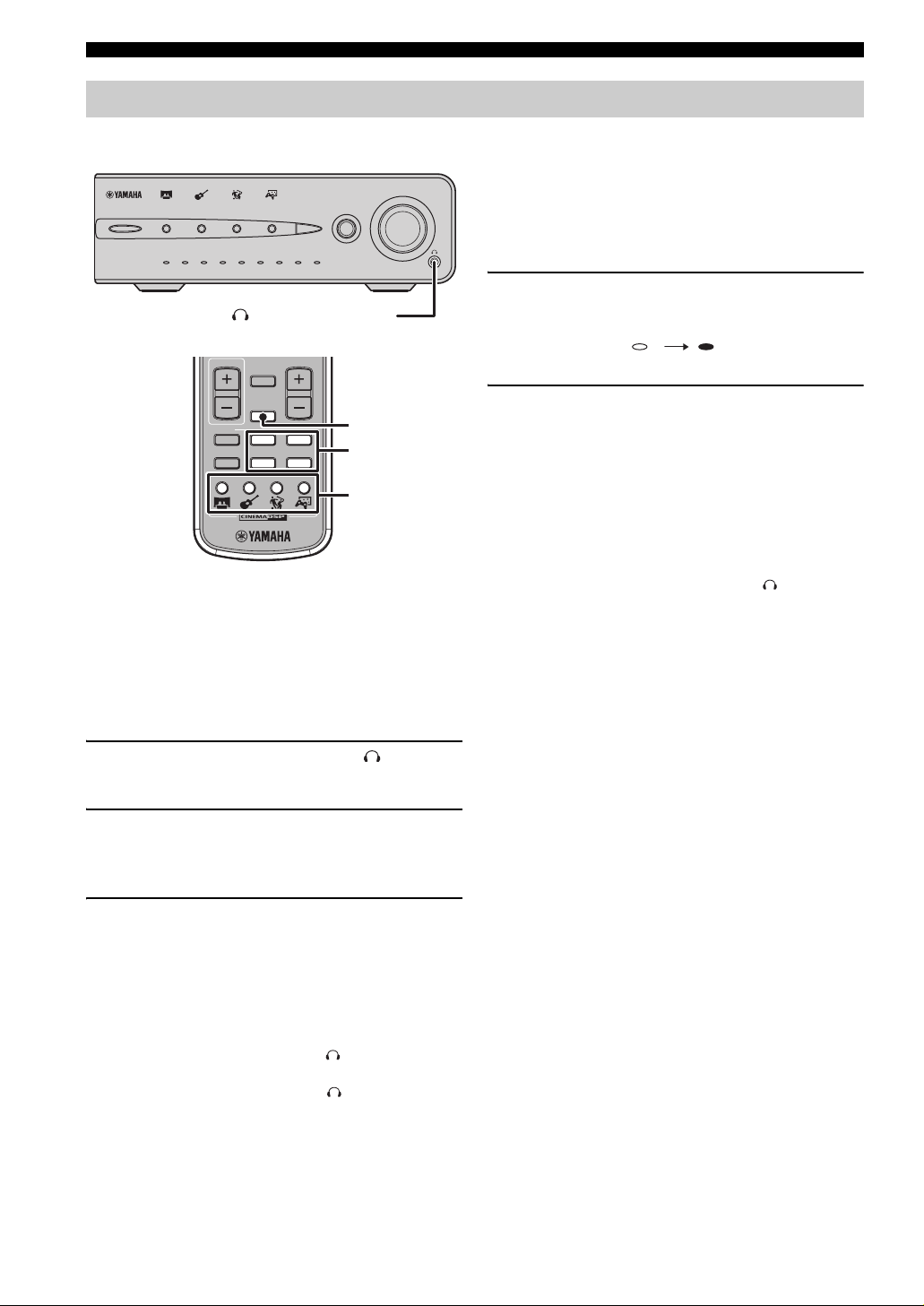
Controls and Functions
9
■ Front panel
STANDBY/ON
MOVIE
MUSIC
3
SPORTS
GAME
MODE
INPUT
PREPARATION
PREPARATION
864712 5
VOLUME
4321
NIGHT MUSICMOVIEAU TODTS qVS
qDigital
12345
0+2+4+6+8-8 -6 -4 -2
1 STANDBY/ON
Turn this unit on or set it to the standby mode.
y
While the unit is in the standby mode, the unit consumes a small
amount of power.
2 CINEMA DSP buttons
Select CINEMA DSP programs. (page 13)
3 CINEMA DSP indicator
Lights up the icon for the CINEMA DSP program
currently selected. (page 13)
4 MODE
Switches the Dolby Pro Logic II modes. (page 13)
5 INPUT
Selects an input source.
q Pro Logic II
6789
SILENT CINEMA
0
6 Input indicator
Lights up the input number currently selected.
7 VOLUME
Adjusts the overall volume level.
8 Remote control sensor
Receives signals from the remote control.
9 Status indicator
Shows the input signal type (page 18) or Dolby Pro Logic
II mode (page 13) currently selected. Also, you can check
the volume level (page 18) when adjusting it.
0 SILENT CINEMA jack
Connects the headphones. (page 14)
3
Page 6
PREPARATION
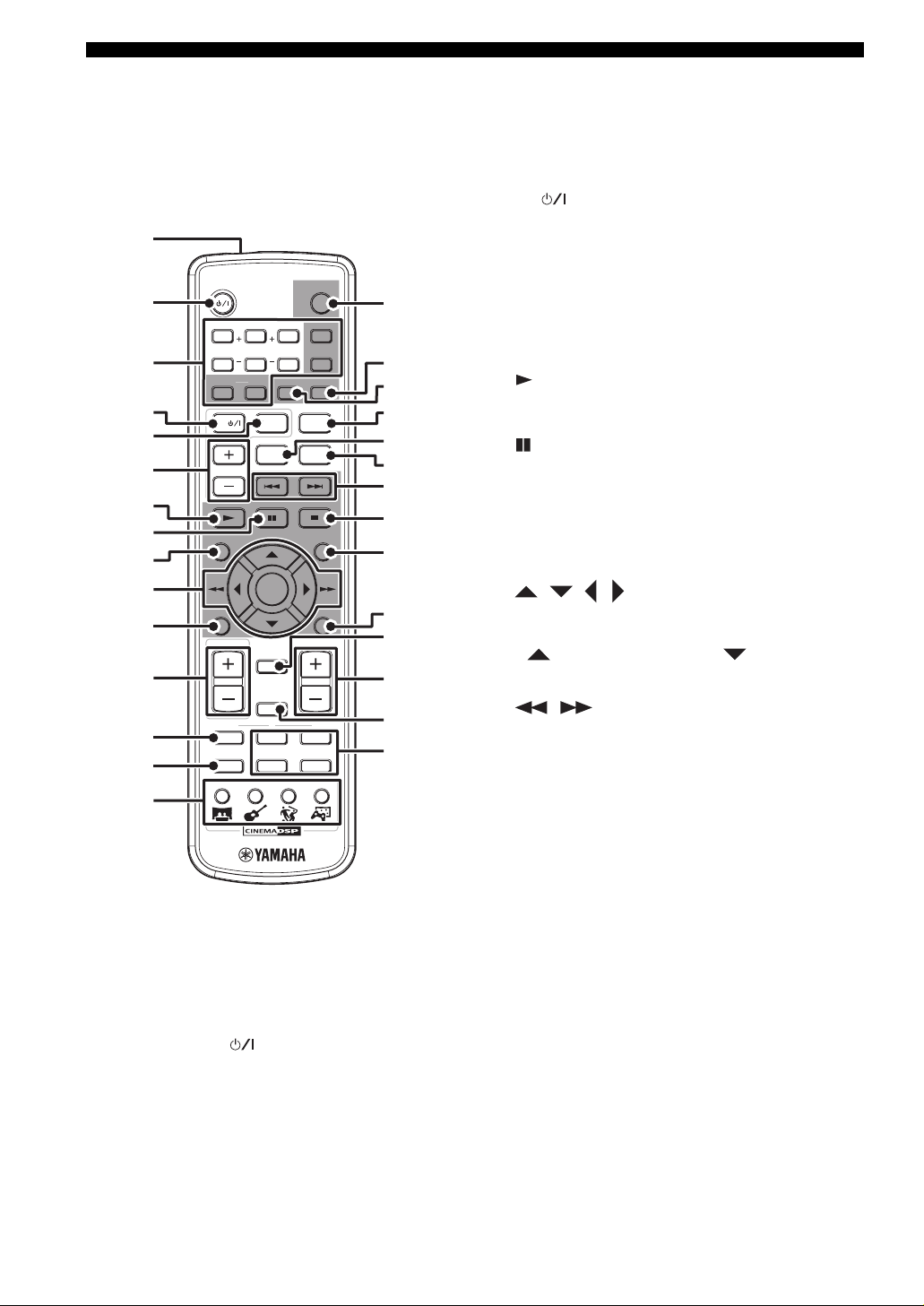
■ Remote control
You can control both the AV amplifier (AVC-S30) and DVD player (DVD-S30) with the supplied remote control. Read
the following for the function of each button. (The buttons shaded in the illustration below are used to control the DVDS30. For details on DVD-S30 operations, refer to the “DVD-S30 OWNER’S MANUAL”.)
1
2
3
4
5
6
STANDBY/ON
SW CENTER SURR
5678
REPEAT SUBTITLEAUDIO
*
*
*
TV
TV CH
A-B
09
TV INPUT
qVS
STANDBY/ON
321
SHIFT
DUAL MONO
DVD
ANGLE
ZOOM
F
4
G
H
I
J
K
L
7
8
9
0
A
B
C
D
ON SCREEN
TV VOL
*
TEST
MODE
MOVIE SPORTS GAMEMUSIC
SETUP
ENTER
RETURNMENU
VOLUME
MUTE
NIGHT
LR
21
INPUT
43
M
N
O
P
Q
R
S
E
*
To control your TV with these buttons, you need to set the
appropriate remote control code. For details, refer to “DVDS30 OWNER’S MANUAL”.
4 TV
*
Turns the TV on, or set it to the standby mode.
5 TV INPUT
*
Switches the TV inputs.
6 TV CH +/–
*
Switches the TV channels.
7 (Play)
Starts disc playback on the DVD-S30.
8 (Pause)
Pauses disc playback on the DVD-S30.
9 ON SCREEN
Displays the On-Screen Menu on the TV screen while
operating the DVD-S30.
0 , , , , ENTER
Operates the On-Screen Menu or specify various
parameters while operating the DVD-S30.
Press to slow reverse and press to slow forward
on the DVD-S30.
, (Search)
Fast forwards/fast reverses playback on the DVD-S30
with a specific speed.
A MENU
Displays the DVD menu on the TV screen while playing
back a DVD on the DVD-S30.
Turns on/off the Playback Control menu on the TV screen
while playing back a VCD on the DVD-S30.
B TV VOLUME +/–
Adjusts the TV volume level.
*
1 Infrared signal transmitter
Sends signals to the units.
2 STANDBY/ON ( )
Turns the AVC-S30 on, or set it to the standby mode.
y
This unit consumes a small amount of power during the standby
mode.
3 Number buttons (1 to 9, 0)
Input numerals to specify parameters such as track or
chapter numbers while operating the DVD-S30.
4
C TEST
Outputs a test tone. (page 15)
D MODE
Switches between the Dolby Pro Logic II modes.
(page 13)
E CINEMA DSP buttons
Selects a CINEMA DSP program. (page 13)
F STANDBY/ON (DVD)
Turns the DVD-S30 on, or set it to the standby mode.
Page 7

PREPARATION
G SUBTITLE
Selects the subtitle language of the DVD video while
operating the DVD-S30.
H AUDIO
Selects the audio language of the DVD video or the audio
channel setting of the VCD and SVCD while operating the
DVD-S30.
I SHIFT
While holding down SHIFT, press a button below to
enable the corresponding operation.
SW +/–: Adjusts the subwoofer channel volume.
(page 16)
CENTER +/–: Adjusts the center speaker channel
volume. (page 16)
SURR +/–: Adjusts the surround speaker channel
volume. (page 16)
ANGLE: Selects the disc viewing angle while operating
the DVD-S30.
ZOOM: Selects the zoom setting of the DVD while
operating the DVD-S30.
REPEAT: Enables the Repeat Play mode on the DVDS30.
A–B: Enables the A-B Repeat mode on the DVD-S30.
R NIGHT
Turns on/off the Night Listening mode. (page 14)
S INPUT buttons
Select an input source.
L/R buttons
While a test tone is output, press L to set the orientation of
the virtual surround speaker (L), and press R to set the
orientation of the virtual surround speaker (R). (page 16,
17)
PREPARATION
J qVS (Dolby Virtual Speaker)
Turns on/off the DVS mode. (page 13)
K DUAL MONO
This button is not used for U.K., Australia, and Asia
models.
L , (Skip)
Skips to the start of current track or next track while
operating the DVD-S30.
Press and hold to fast reverse or to fast
forward disc playback on the DVD-S30.
M (Stop)
Stops disc playback on the DVD-S30.
N SETUP
Displays or closes the Setup menu on the TV while
operating the DVD-S30.
O RETURN
Returns the DVD menu to the previous screen while
operating the DVD-S30.
P MUTE
Turns off the volume.
Q VOLUME +/–
Adjusts the overall volume level.
5
Page 8
PREPARATION
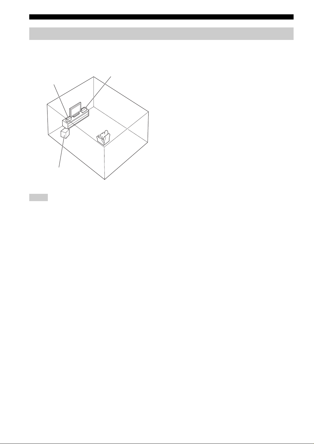
Placing the Speakers
To enjoy quality sounds thoroughly, you need to place the speakers in their appropriate positions and install them
correctly. After deciding the speaker layout, follow the procedure below to install the speakers.
Satellite speaker (R)
Satellite speaker (L)
Place the left/right speakers on both sides of your TV at equal
distances. We recommend that you place the speakers at the
height of your ears at the listening position, and keep the speakers
at least 80 cm (2’ 6”) apart while they are placed 80 cm (2’ 6”)
away from the side walls.
Main roles: Produces front channel (stereo) sounds. Also
produces center channel sounds (dialogues or vocal sounds) and
surround channel sounds effectively using the Yamaha Air
Surround system.
Subwoofer (NX-SW30)
Satellite speakers (L, R) (NX-S30)
Place the subwoofer near a front speaker and turn it slightly
toward the center of the room to reduce wall reflections.
Main roles: Produces bass sounds and low frequency (LFE)
sounds contained in Dolby Digital or DTS.
Subwoofer
Notes
• Be sure to place the satellite speaker (L) on the left of the TV and the satellite speaker (R) on the left of the TV since the speakers are
not symmetrical. Check the (L) and (R) marks printed on the back of each speaker to identify them.
• To create better acoustic field, you need to place the satellite speakers properly and adjust the orientation of the virtual surround
speakers suited for your listening environment. Also, the arrangement of furniture affects the acoustic field. For details, refer to
“Adjusting the Orientation of the Virtual Surround Speakers” (page 16).
• If the speakers interfere with TV reception, noises may appear on the TV screen. In such a case, move the speakers a little away from
the TV.
• Bass sounds produced by the subwoofer may be heard differently depending on the listening position and subwoofer location.
To enjoy desired sounds, try to change the location of the subwoofer according to the listening position.
6
Page 9
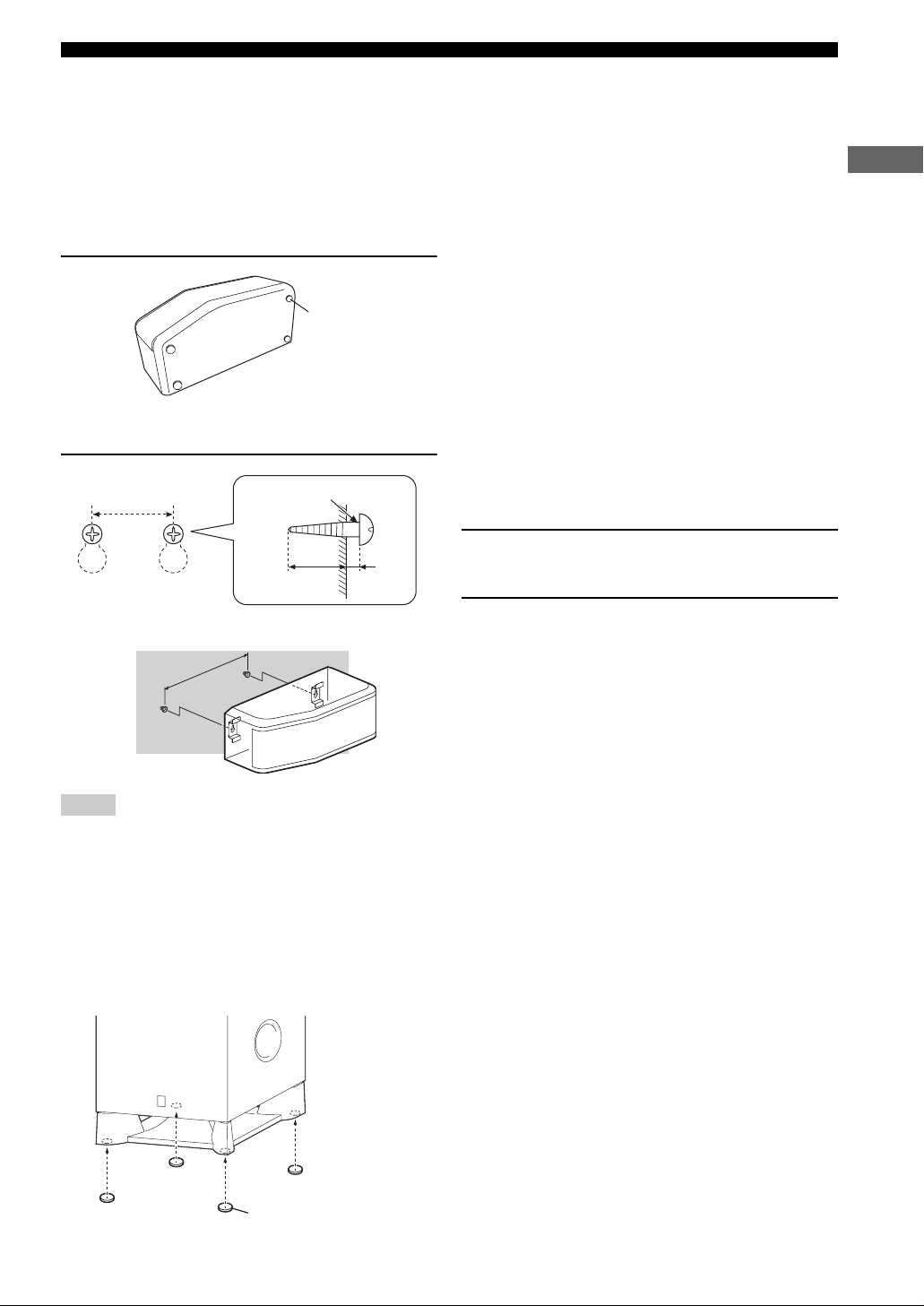
PREPARATION
■ Placing the Satellite Speakers
You can place the satellite speakers on a rack, or attach them to a wall. Please select an installation method that suits your
room layout.
y
You can attach the satellite speaker to a commercially available speaker bracket or speaker stand using the screw holes on the bottom of
the speakers. In this case, be sure to use 6M (diameter of 6 mm) screws.
To place on a rack
Attach the non-skid pads (small) to the bottom of
each speaker, and then place them on level hard
Non-skid pad
(small)
To attach to a wall
surfaces.
y
Using non-skid pads prevents the speakers from sliding when
they vibrate, and ensures quality sound production.
PREPARATION
198 mm
(7-25/32”)
Diameter of 3.5 to 4 mm
(1/8” to 5/32”)
You can attach the speakers to a wall using commercially
available screws (Diameter: 3.5 to 4 mm (1/8” to 5/32”), Length:
24 mm (15/16”) or more). One speaker requires two screws.
1 Install two screws in the wall where you want
20 mm (25/32”)
or more
4 mm
(5/32”)
to place the speaker.
2 Hang the speaker on the screws using the
198 mm (7-25/32”)
Notes
• One speaker weighs about 1.4 kg (3 lbs 3 oz). To attach a speaker to a wall using screws, the wall must be firm. Do not attach a speaker
to a wall that is made of weak materials such as plaster or veneered woods. Doing so may cause the speaker to fall.
• Make sure you use specified screws to attach a speaker to a wall. Using clamps other than specified screws, such as short screws, nails,
or two-sided tape, may cause the speaker to fall.
• When connecting the speakers, fix the speaker cables in place so that cables do not loosen. If your foot or hand accidentally gets
caught on a loose speaker cable, the speaker may fall.
• After attaching each speaker, check that the speaker is fixed securely. YAMAHA will bear no responsibility for any accidents caused
by improper installations.
holes in the back of the speaker.
■ Placing the subwoofer
Non-skid pad (large)
Attach the non-skid pads (large) to the bottom of
the subwoofer, and then place the subwoofer on
a level hard floor.
y
Using non-skid pads prevents the subwoofer from sliding when it
vibrates, and ensures quality sound production.
7
Page 10
PREPARATION
Connecting the Speakers
Follow the procedure below to connect the satellite speakers (NX-S30) and subwoofer (NX-SW30) to the AV amplifier
(AVC-S30).
Notes
• Do not connect the power cables of the AV amplifier and subwoofer until all cable connections are completed.
• Do not use excessive force when inserting the cable plug. Doing so may damage the cable plug or speaker jack.
Connect the cable plugs to the
speaker jack of the same color until
you hear a click.
White: Insert the cable plug facing the tub
upwards.
Red: Insert the cable plug facing the tub
downwards.
SPEAKERS
Tab
L
R
SPEAKER IMPE
D
AN
C
E
:6Ω
M
IN
.
Satellite speaker (L)
Satellite cable
(supplied, white plug)
To A C o utlet
System control cable
(supplied)
SYSTEM
INPUT
CONNECTOR
Subwoofer
INPUT
4231
L
R
SYSTEM
SUBWOOFER
OUT
CONNECTOR
Subwoofer cable (supplied)
To A C outl e t
AV amplifier
SPEAKERS
L
R
SPEAKER IMPEDANCE:6ΩMIN.
Satellite cable
(supplied, red plug)
Satellite speaker (R)
8
Page 11
PREPARATION
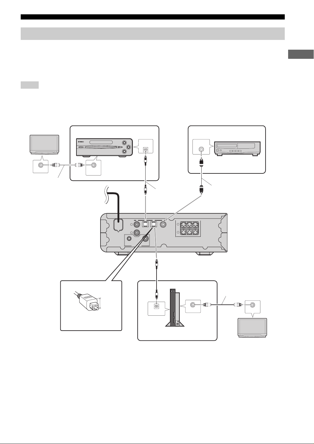
Connecting External Components
The AV amplifier “AVC-S30” has four input jacks (optical digital x 2, coaxial digital x 1, analog x 1). Before connecting
your external components to the AV amplifier, check the output jacks of the components and be sure to use correct
connection cables.
■ Digital connection
Notes
• Do not connect the power cables of the AV amplifier and external components until all cable connections are completed.
• The digital terminals of this unit support PCM, Dolby Digital, DTS signal system.
• The digital terminals support digital signals of which sampling frequency is 96 kHz or less.
PREPARATION
TV (monitor)
VIDEO INPUT
Video pin cable
(supplied with
DVD- S30)
DVD player (DVD-S30)
VIDEO OUT
(VIDEO)
To A C ou t l et
About optical cables
14 mm
Use an optical cable with
the plug of 14 mm or less
(shown above).
s
e
CONNECTOR
SYSTEM
p
INPUT
L
R
SUBWOOFER
DIGITAL OUT
(OPTICAL)
Optical cable
(supplied with
DVD- S30)
4231
OUT
Optical cable
(commercially available)
OPTICAL
DIGITAL OUTPUT
TV game console etc.
DIGITAL OUTPUT
SPEAKERS
L
R
SPEAKER IMPEDANCE:6ΩMIN.
VIDEO OUTPUT
CD player with coaxial
digital output
COAXIAL
Coaxial cable
(commercially available)
Video pin cable
(commercially
available)
VIDEO INPUT
TV (monitor)
9
Page 12
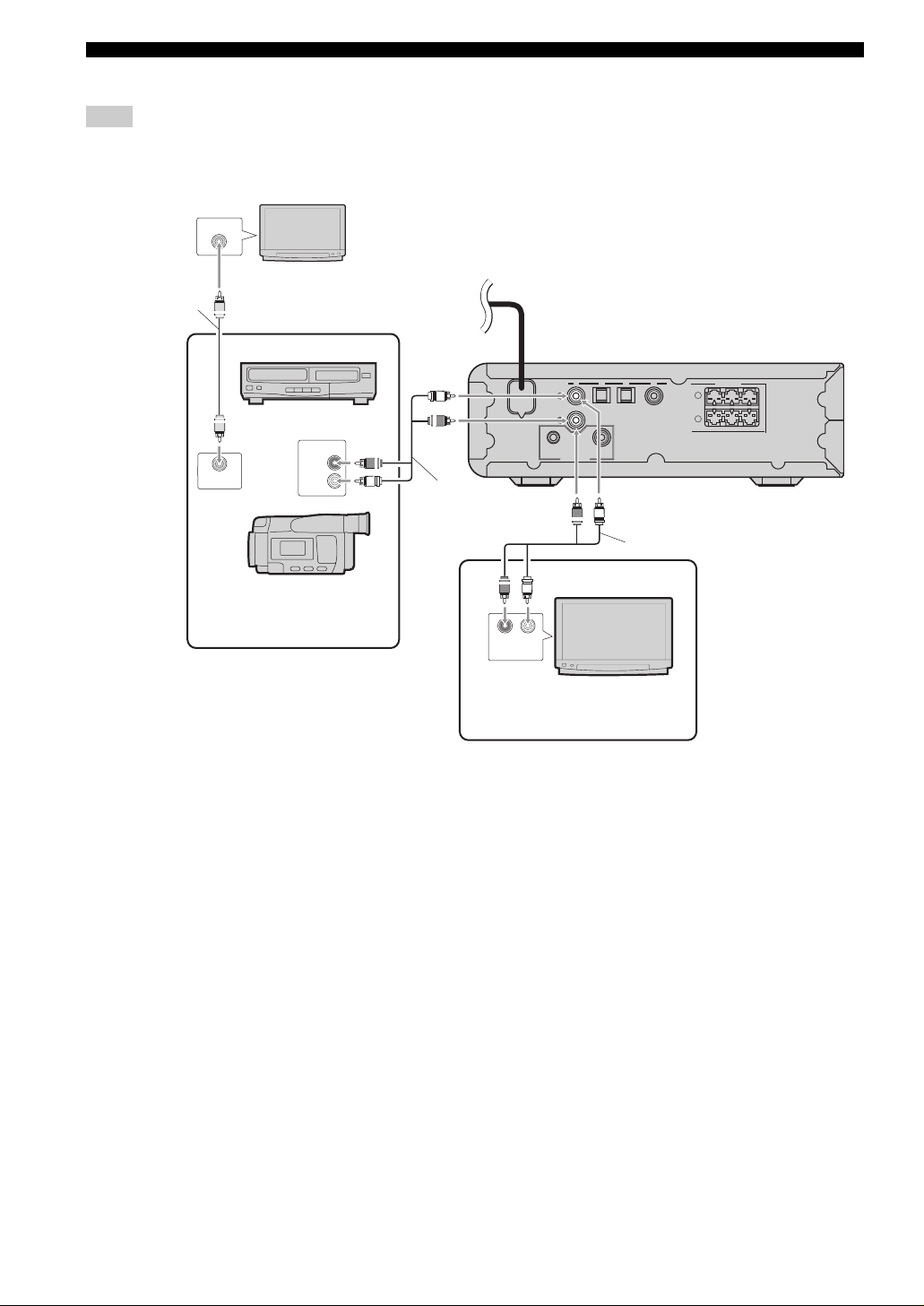
PREPARATION
■ Analog connection
Note
Do not connect the power cables of the AV amplifier and external components until all cable connections are completed.
TV (monitor)
VIDEO INPUT
Video pin cable
(commercially
available)
VIDEO OUTPUT
VCR etc.
AUDIO OUTPUT
R
L
(R)
(L)
To AC outlet
(L)
(R)
Audio pin
cable
(commercially
available)
SYSTEM
CONNECTOR
(R)
INPUT
L
R
SUBWOOFER
4231
L
R
SPEAKER IMPEDANCE:6ΩMIN.
OUT
(L)
Audio pin cable
(commercially available)
SPEAKERS
Video camera or TV game
console etc. with no digital
output
RL
AUDIO OUTPUT
(L)(R)
TV
Connect the TV to the AV
amplifier to enjoy TV sounds on
the system.
10
Page 13

PREPARATION
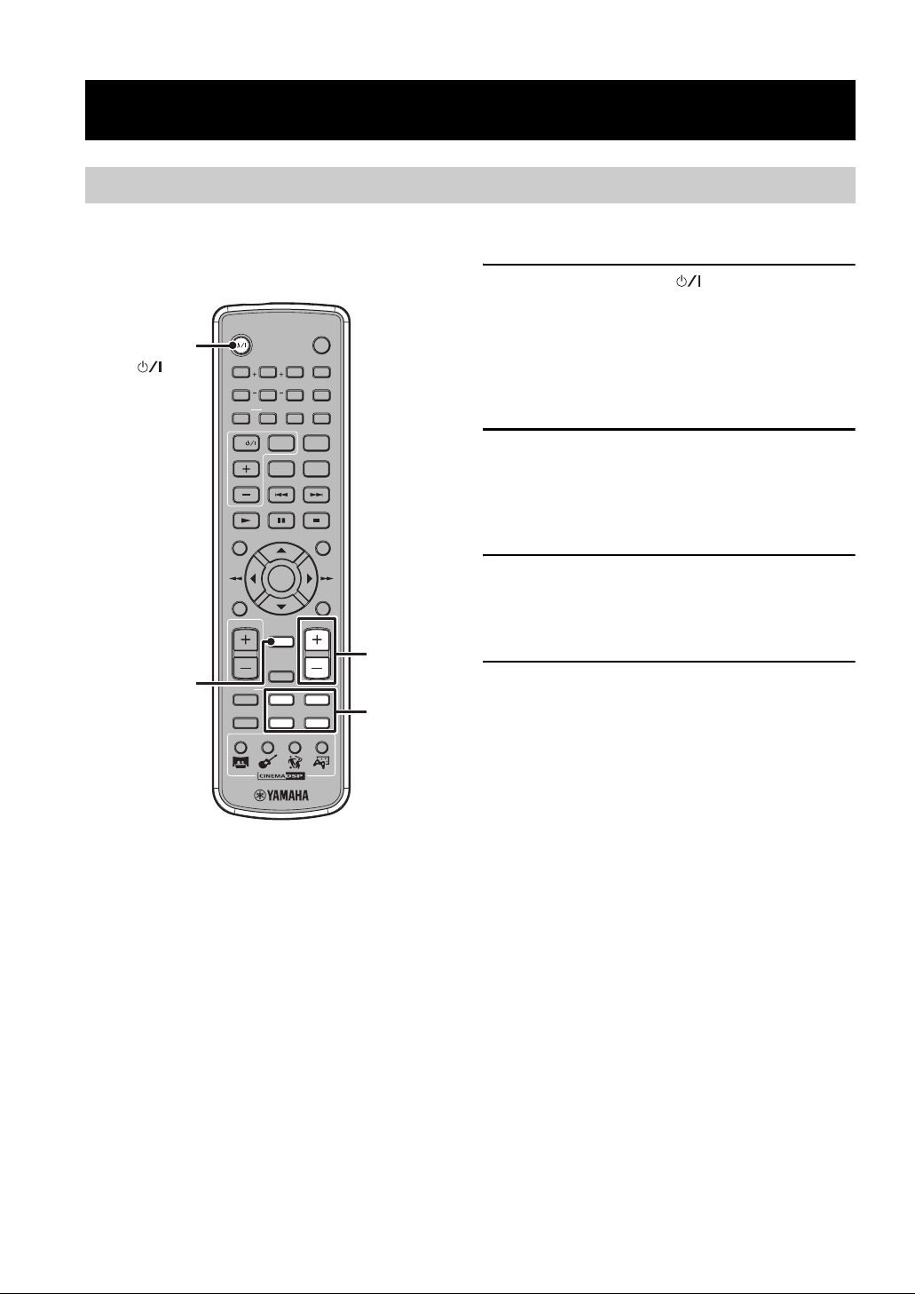
Using the Remote Control
Use the remote control within 6 m (20 feet) of the AV
amplifier and point it toward the remote control sensor.
VOLUME
STANDBY/ON
MOVIE
MUSIC
NIGHT MUSICMOVIEAUTODTS qVS
qDigital
12345
SPORTS
0+2+4+6+8-8 -6 -4 -2
GAME
MODE
q Pro Logic II
6789
INPUT
Within 6 m
SILENT CINEMA
4321
(20 feet)
30˚ 30˚
■ Replacing the batteries
If the batteries grow old, the effective operation distance of the remote control decreases considerably. If this happens, replace the
batteries with two new ones as soon as possible.
Notes
• Be careful not to spill liquid on the remote control.
• Be careful not to drop the remote control.
• Do not leave the remote control in the following places:
– hot or humid places, such as near a heater or in a bathroom
– extremely cold places
– dusty places
1 Press the mark on the battery cover and
slide off the cover.
PREPARATION
2 Insert the two new batteries (AA, R06, UM-3)
into the battery compartment.
Press
Make sure you insert the batteries according to the
polarity markings (+ and –).
3 Close the battery cover.
Notes
• Do not use an old battery together with new one.
• Do not use different types of batteries (for example, alkaline and manganese) together. Each type of battery has its own characteristics
even if they are similar in shape.
• If the batteries run out, immediately remove them from the remote control to prevent an explosion or acid leak.
• Dispose of the batteries according to the regional regulations.
• If a battery starts leaking, dispose of it immediately. Be careful not to let leaking battery acid come into contact with your skin or
clothing. Before inserting new batteries, wipe the compartment clean.
• Replace the batteries within two minutes to preserve the memory in the remote control.
11
Page 14
OPERATION
OPERATION
Basic Operation
Once you have finished all cable connections (pages 8-10) and remote control preparation (page 11), follow the
procedure below to start from basic playback operation.
1 Press STANDBY/ON ( ).
This unit turns on and the indicators on the front
panel light up.
y
This unit has the auto-sleep function which automatically
switches to the standby mode if you do not operate the unit
for about 24 hours while the unit is turned on.
2 Press one of the INPUT buttons (1 to 4) to
select an input source.
For example, if the DVD-S30 is connected to the
INPUT (1) jack on the rear panel of this unit, press
INPUT (1) to select the DVD-S30.
STANDBY/ON
()
STANDBY/ON
SW CENTER SURR
5678
REPEAT SUBTITLEAUDIO
A-B
09
TV
TV INPUT
qVS
TV CH
ON SCREEN
STANDBY/ON
321
DVD
ANGLE
ZOOM
SHIFT
DUAL MONO
SETUP
4
MUTE
TV VOL
TEST
MODE
MOVIE SPORTS GAMEMUSIC
ENTER
RETURNMENU
VOLUME
MUTE
NIGHT
LR
21
INPUT
43
VOLUME
+/–
INPUT
buttons
3 Start playback on the selected external
component.
For information on the external component, refer to
the manual for that product.
4 Press VOLUME +/– to adjust the volume
level.
y
To turn off the volume temporarily, press MUTE. While the
mute function is on, the Input indicators (other than one
currently selected) blink. To disable the mute function, press
MUTE once again.
Now, please try various features of this unit!
To enjoy high realistic sensational sounds with a DSP
program
→ “Enjoying realistic sounds (CINEMA DSP)” (page 13)
To enjoy stereo sounds such as CD audio with virtual
multi channels
→ “Enjoying stereo sounds with multi speaker channels (Dolby
Pro Logic II)” (page 13)
To enjoy virtual surround sounds with the DVS function
→ “Using the DVS function (Dolby Virtual Speaker)” (page 13)
To configure the orientation of virtual surround
speakers
→ “Adjusting the Orientation of the Virtual Surround Speakers”
(page 16)
12
Page 15
OPERATION
Enjoying Sounds with Specific Speaker Channels
The sound program features allow you to enjoy various kinds of audio such as movie or music. Please choose a program
based on your listening preference, and not purely on the name of the program.
y
This unit automatically memorizes the settings assigned to each input (1 to 4). If you select another input, the unit automatically recalls
the last settings for the selected input.
■ Enjoying stereo sounds with multi speaker channels (Dolby Pro Logic II)
The Dolby Pro Logic II modes reproduce 5.1-channel
audio from the stereo sounds.
Press MODE repeatedly to select the desired
Dolby Pro Logic mode.
Each time you press the button, the mode changes as
follows.
q
Pro Logic II
q
Pro Logic II
q
Pro Logic II
MUSICMOVIEAUTO
MUSICMOVIEAUTO
MUSICMOVIEAUTO
678
AUTO (q Pro Logic II Off)
678
q Pro Logic II MOVIE
678
q Pro Logic II MUSIC
MODE
TV
TV CH
ON SCREEN
TV VOL
TEST
MODE
MOVIE SPORTS GAMEMUSIC
SHIFT
TV INPUT
DUAL MONO
VS
q
SETUP
ENTER
RETURNMENU
VOLUME
MUTE
NIGHT
LR
21
INPUT
43
qVS
CINEMA DSP
buttons
OPERATION
■ Enjoying realistic sounds (CINEMA DSP)
The CINEMA DSP programs reproduce realistic sounds
with the multi speaker channels.
Press one of the CINEMA DSP buttons.
The icon for the selected CINEMA DSP program lights
up.
The characteristics of each CINEMA DSP program are as
follows.
Movie
Produces the rich acoustical presence of a movie theater.
Music
Magnifies the feeling of listening to live rock or jazz in a
concert hall.
Sports program
In a live stereo sports broadcast, announcer voices are
central, engulfed in the cheers and emotional whirl of the
stadium.
Game program
Gives TV games extra depth and surround.
To reproduce the original sounds, press the
CINEMA DSP button currently selected or MODE.
■ Using the DVS function (Dolby Virtual Speaker)
The Dolby Virtual Speaker (DVS) function reproduces
5.1-channel-like realistic sensational sounds with the front
and subwoofer channels only.
Press qVS.
The Status indicator (qVS) lights up.
To disable the DVS function, press qVS once again.
qVS
y
• Activating the DVS function automatically cancels the
CINEMA DSP program currently selected. Also, you cannot
select a CINEMA DSP program while the DVS function is
activated. To select a CINEMA DSP program, press qVS to
disable the DVS function.
• Activating the DVS function while a stereo signal is input
automatically selects the Dolby Pro Logic II Movie mode.
• When a Mono or Dual Mono signal is input, the DVS function
is not available.
• When headphones are connected to the SILENT CINEMA
jack on the unit, the DVS function is not available.
qVS
99
13
Page 16
OPERATION
Enjoying Sounds in a Variety of Ways
You can enjoy the presence of sound effects even when you use headphones or reduce the volume level.
VOLUME
4321
STANDBY/ON
MOVIE
MUSIC
NIGHT MUSICMOVIEAUTODTS qVS
qDigital
12345
SPORTS
0+2+4+6+8-8 -6 -4 -2
GAME
q Pro Logic II
6789
INPUT
MODE
SILENT CINEMA
SILENT CINEMA jack
TV VOL
TEST
MODE
MOVIE SPORTS GAMEMUSIC
VOLUME
MUTE
NIGHT
LR
21
INPUT
43
NIGHT
INPUT
buttons
CINEMA DSP
buttons
■ Listening with headphones (“SILENT CINEMA”)
“SILENT CINEMA” allows you to enjoy multi-speaker
simulation sounds with headphones.
*
“SILENT CINEMA” is a registered trademark of YAMAHA
CORPORATION.
■ Listening at low volume (Night Listening)
The Night Listening function tones down large sound
effect and clears speech or vocal sounds.
1 Press NIGHT.
The Status indicator (NIGHT) lights up.
NIGHT
NIGHT
1
1
2 Press the INPUT button for the desired input
source, then start playback on the external
component.
To disable the Night Listening function, press
NIGHT once again.
y
• If you activate a CINEMA DSP program or the DVS
function with the Night Listening function, you can enjoy
realistic sensational sounds at low volume.
• When headphones are connected to the SILENT
CINEMA jack on the unit, the Night Listening functions
is not available.
1 Connect the headphones to the SILENT
CINEMA jack on the unit.
2 Press the INPUT button for the desired input
source, then start playback on the external
component.
3 As needed, press the CINEMA DSP button for
the desired CINEMA DSP program.
y
• Low frequency sounds (LFE signals) are mixed with other
channel audio.
• If you do not select a CINEMA DSP program when a stereo
signal is input, the headphone produces normal stereo sound.
• When headphones are connected to the SILENT CINEMA
jack, the speakers do not output any sounds.
• When headphones are connected to the SILENT CINEMA
jack on the unit, the DVS function is not available.
14
Page 17
CONFIGURATIONS
CONFIGURATIONS
Adjusting the Speaker Balance
The initial speaker settings are suitable for most conditions. However, depending on room conditions or listening
position, you may need to adjust the speaker balance manually. In this case, adjust the speaker balance using test tones at
first.
y
• When headphones are connected to the SILENT CINEMA jack on the unit, the adjustment is not available.
• Adjust the speaker balance at your listening position with the remote control.
■ Adjusting the speaker balance with test tones
ON SCREEN
SETUP
CONFIGURATIONS
ENTER
RETURNMENU
VOLUME
MUTE
NIGHT
LR
21
INPUT
43
VOLUME +/–
TEST
TV VOL
TEST
MODE
MOVIE SPORTS GAMEMUSIC
1 Press TEST.
The CINEMA DSP indicators blink and each speaker
outputs the test tone for about 2.5 seconds in order.
2 While a test tone is output from the speaker
channel you want to adjust, press VOLUME
+/– to adjust the volume level of the currently
selected speaker channel.
Front (L)
Subwoofer
Surround
(L)
: Satellite speaker and subwoofer
: Virtual speaker
Center
Front (R)
Surround
(R)
3 To confirm the adjustment, press TEST.
y
• You can check the volume level in detail with the Status
indicator (page 18).
• While adjusting the volume level of a speaker, other speakers do
not output test tones.
• The adjustable range for the volume level of each speaker
channel is as follows.
– Front (L, R): –6 (Min) to ±0 dB (Max)
– Center: –4 (Min) to + 4 dB (Max)
– Surround (L, R): –4 (Min) to +4 dB (Max)
– Subwoofer: –8 (Min) to +8 dB (Max)
• You cannot adjust the volume level of the center speaker
channel and surround speaker channels while the DVS function
is activated.
• To reset the volume level of all speaker channels to the factory
settings, press INPUT on the front panel while a test tone is
output. (This procedure also resets the orientations of the virtual
surround speakers.)
15
Page 18
CONFIGURATIONS
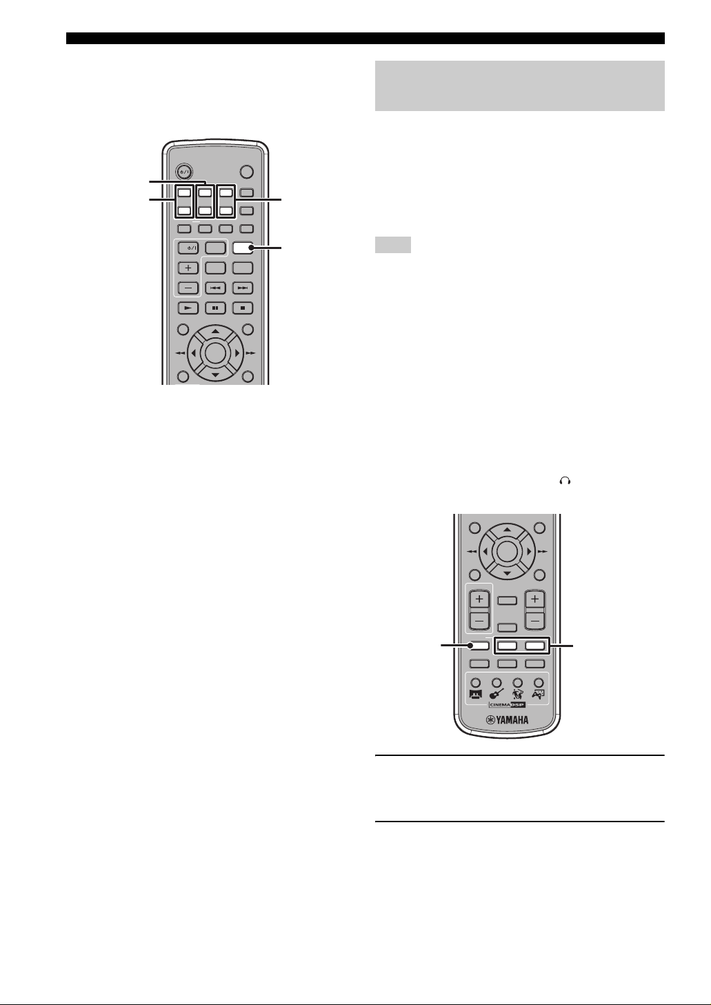
■ Adjusting the speaker balance during playback
If you feel the speaker balance is not proper during
playback, follow the procedure below.
STANDBY/ON
CENTER +/–
SW +/–
SW CENTER SURR
5678
REPEAT SUBTITLEAUDIO
TV
TV CH
ON SCREEN
During playback, carry out the following
operation for your purpose.
To adjust the volume level of the center speaker
channel:
While holding down SHIFT, press CENTER +/–.
To adjust the volume level of the surround
speaker channels:
While holding down SHIFT, press SURR +/–.
To adjust the volume level of the subwoofer
channel:
While holding down SHIFT, press SW +/–.
y
• We recommend that you first adjust the speaker balance with
test tones (page 15).
• You can check the volume level in detail with the Status
indicator (page 18).
• The adjustable range for the volume level of each speaker
channel is as follows.
– Center: –4 (Min) to + 4 dB (Max)
– Surround: –4 (Min) to +4 dB (Max)
– Subwoofer: –8 (Min) to +8 dB (Max)
• You cannot adjust the left and right surround speakers
individually with this procedure. To adjust them individually,
carry out the “Adjusting the speaker balance with test tones”
procedure (page 15).
STANDBY/ON
DVD
ANGLE
4321
ZOOM
A-B
09
SHIFT
TV INPUT
DUAL MONO
VS
q
SETUP
ENTER
RETURNMENU
SURR +/–
SHIFT
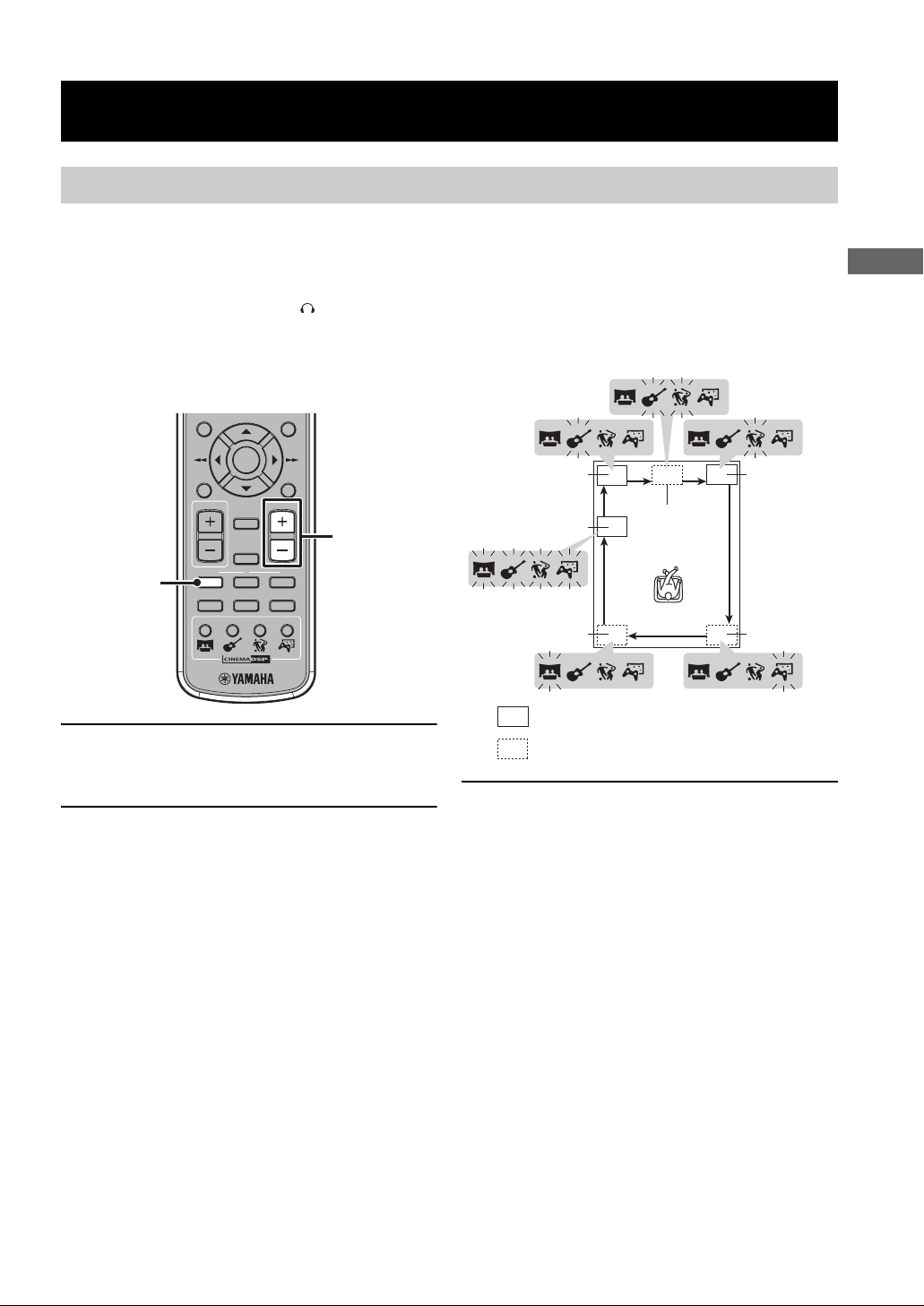
Adjusting the Orientation of the Virtual Surround Speakers
This unit employs the Yamaha Air Surround system that
enables the surround sound field using six speaker units
built in two satellite speakers. To create better acoustic
field, please adjust the orientation of the virtual surround
speakers suited for your listening environment. You can
select from five presets for each satellite speaker (L and
R).
Note
To create better acoustic field, you may need to change the
arrangement of the satellite speakers or furniture. For example,
the Air Surround system does not work well (or does not work at
all) in the following situations.
– The satellite speakers are placed inside the rack.
– The satellite speakers are not placed perpendicular to the side
walls.
– There is an obstacle at the front (or diagonally in front) of
satellite speakers.
– A piece of furniture is placed at the reflection points (A, B).
– There are no reflection faces (walls or windows).
y
• You cannot adjust the orientation of the virtual surround
speakers while the DVS function is activated. To adjust it, press
qVS to disable the DVS function.
• When headphones are connected to the SILENT CINEMA
jack on the unit, the adjustment is not available.
ON SCREEN
TV VOL
TEST
TEST
MODE
MOVIE SPORTS GAMEMUSIC
1 Press TEST.
Each speaker outputs the test tone for about 2.5
seconds in order.
SETUP
ENTER
RETURNMENU
VOLUME
MUTE
NIGHT
LR
21
INPUT
43
L/R
16
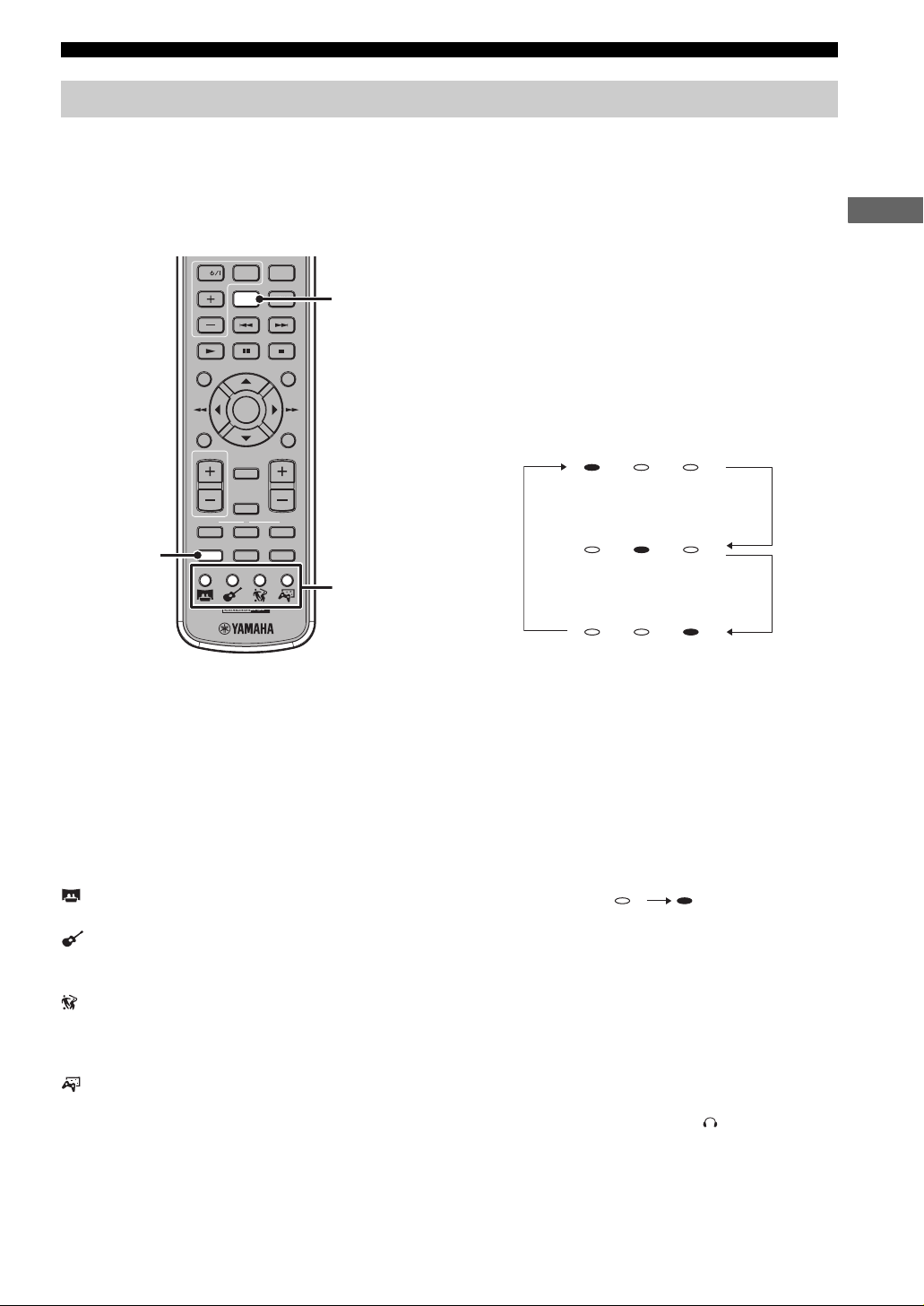
2 Press L once to check the current orientation
of the virtual left surround speaker, or press
R once to check the current orientation of the
virtual right surround speaker.
The Status indicator blinks to show the current
orientation for about 2.5 seconds. By the factory
setting, “40°” is selected for each speaker.
Page 19

CONFIGURATIONS
3 While the Status indicator is blinking, press L
repeatedly to select an orientation of the
virtual left surround speaker, or press R
repeatedly to select an orientation of the
virtual right surround speaker.
Each time you press the button, the orientation
changes as follows.
20°
(Five status indicators from
the right or left light up)
30°
(Four status indicators from
the right or left light up)
40°
(Three status indicators from
the right or left light up)
50°
(Two status indicators from
the right or left light up)
60°
(Rightmost or leftmost status indicator
lights up)
y
Adjust the angle so that the first reflection point (A) is located
posterior to the listening position and surround speaker channel
audio reaches the listening position after reflections as shown
below. For information on the recommended listening
environment and virtual surround speaker settings, refer to
“Recommended Virtual Surround Speaker Settings” (page 20).
Satellite speaker (L) Satellite speaker (R)
Press L to
adjust
A
BB
Satellite speaker (L) Satellite speaker (R)
Press L to
adjust
A
B
Press R to
adjust
A
Press R to
adjust
A
B
4 To confirm the adjustment, press TEST.
y
To reset the orientations to the factory settings, press INPUT on
the front panel while a test tone is output. (This procedure also
resets the speaker balance.)
CONFIGURATIONS
17
Page 20

ADDITIONAL INFORMATION
q
q
ADDITIONAL INFORMATION
Status Indicator
You can check the volume level or audio input signal types on the Status indicator.
■ Volume level
Volume level of each speaker channel (difference based on the system volume, unit: dB)
Status
indicator
1
-8
1-82
-6
2
-6
2-63
-4
3
-4
3-44
-2
4
-2
4-25
0
0
(green)
Front (L, R)
–6 –5 –4 –3 –2 –1.5 –1 –0.5 ±0
Center,
Surround
–4 –3.5 –3 –2.5 –2 –1.5 –1 –0.5 ±0
(L, R)
Subwoofer
Status
indicator
–8 –7 –6 –5 –4 –3 –2 –1 ±0
6
5
+2
0
6
+2
+26+4
7
7
+4
+47+6
8
8
+6
+68+8
9
9
+8
(green)
Front (L, R)
––––––––
Center,
Surround
+0.5 +1 +1.5 +2 +2.5 +3 +3.5 +4
(L, R)
Subwoofer
+1 +2 +3 +4 +5 +6 +7 +8
■ Input signal
This unit automatically handles input signals. You cannot switch the signal type manually. For details on each signal
type, refer to “Glossary” (page 21).
Digital
23456
AUTODTS
When a Dolby Digital signal is input
5
Digital
23456
23456
AUTODTS
AUTODTSqDigital
When a DTS signal is input
When an analog signal or PCM signal is input
y
The status indicator “AUTO” turns off when one of the CINEMA DSP programs or Dolby Pro Logic modes is selected.
18
Page 21

ADDITIONAL INFORMATION
Troubleshooting
If there is any problem with this unit, check the following items. If you cannot solve your problem with the following
remedies or if your problem is not listed below, turn off and unplug this unit, then consult the nearest authorized
YAMAHA dealer or service center.
Problem Cause Solution
Power turns on but immediately
shuts off
The speakers make no sound The volume may be set to minimum level. Adjust the volume level. (page 12)
Sound is too low on one side The cables may be connected improperly. Make sure all cables are connected properly.
Speaker channels other than the
front ones make no sound
The center speaker channel
makes no sound
The surround speaker channels
make no sound
The subwoofer makes no sound The volume of the subwoofer may be set to
Sound is poor (noisy) The speaker cable may be shorted. Make sure all cables are connected properly.
This unit does not operate
properly
A digital or high-frequency
equipment produces noises
The remote control does not work
for operating this unit
The power cable may be connected
improperly.
The speaker cable may be shorted. Make sure all speaker cables are connected
This unit may receive a strong electrical
shock such as from a lightening bolt or
excessive static electricity.
The Mute function may be enabled. Cancel the Mute function. (page 12)
The input source or input setting may be
incorrect.
The cables may be connected improperly. Make sure all cables are connected properly.
You may be listening to stereo sounds
without the sound field effect.
You may be listening to an audio source
(Dolby Digital or DTS) that does not
contain any special effect signal.
The volume of the center speaker channel
may be set to minimum level.
You may be listening to a Dolby Digital or
DTS audio source.
The volume of the surround speaker
channels may be set to minimum level.
minimum level.
The subwoofer cable or system control
cable may be connected improperly.
You may be listening to an audio source that
does not contain any low tone signal.
This unit may receive a strong electrical
shock, such as from a lightening bolt or
excessive static electricity, or drop in power
supply.
This unit may be placed close to the digital
equipment or high-frequency equipment.
This unit may be operated outside the
remote control operation range.
The remote control sensor on this unit may
be exposed to direct sunlight or lighting.
The batteries may be worn out. Replace the batteries. (page 11)
Make sure the power cable is plugged into the
outlet firmly.
properly.
Set this unit to the Standby mode, then
disconnect the power cable. Wait for about 30
seconds, then connect the power cable and turn
on this unit.
Select the correct input source or input setting.
(page 12)
(pages 8-10)
(pages 8-10)
Press CINEMA DSP to enable the sound field
effect. (page 13)
Select another sound field program. (page 13)
Adjust the volume level of the center speaker
channel using test tones. (page 15)
Dolby Digital and DTS audio sources do not
contain a center speaker signal.
Adjust the volume level of the surround
speaker channels using test tones. (page 15)
Adjust the volume level of the subwoofer.
(page 15)
Make sure all cables are connected properly.
(page 8)
The subwoofer does not support signals
outside the specified range.
(pages 8-10)
Set this unit to the Standby mode, then
disconnect the power cable. Wait for about 30
seconds, then connect the power cable and turn
on this unit.
Place this unit further away from such
equipment.
For information on the remote control
operation range, refer to “Using the Remote
Control” (page 11).
Change the lighting or this unit’s orientation.
ADDITIONAL INFORMATION
19
Page 22

ADDITIONAL INFORMATION
Recommended Virtual Surround Speaker Settings
If you cannot adjust the orientation of the virtual surround speakers well (page 16), use the following information for
reference.
Note
To create better acoustic field, you may need to change the arrangement of the satellite speakers or furniture.
Satellite speaker (L) Satellite speaker (R)
3
1
TV
1.1 m
(3.6 ft)
0.6 m
(2.0 ft)
4
5
0.7 m
(2.3 ft)
2
Room size:
(Length 1 × Width 2)
2.7 m × 2.7 m (8.8 ft × 8.8 ft) 0.8 m (2.6 ft) 1.4 m (4.6 ft) 30°
3.6 m × 2.7 m (11.8 ft × 8.8 ft)
2.7 m × 3.6 m (8.8 ft × 11.8 ft)
3.6 m × 3.6 m (11.8 ft × 11.8 ft)
3.6 m × 4.5 m (11.8 ft × 14.8 ft)
4.5 m × 3.6 m (14.8 ft × 11.8 ft)
Distance of satellite speakers
and side walls:
3 and 4
0.8 m (2.6 ft) 1.4 m (4.6 ft) 30°
0.8 m (2.6 ft) 2.2 m (7.2 ft) 20°
0.8 m (2.6 ft) 1.4 m (4.6 ft) 30°
1.2 m (3.9 ft) 1.4 m (4.6 ft) 40°
1.6 m (5.2 ft) 1.3 m (4.3 ft) 50°
0.8 m (2.6 ft) 2.2 m (7.2 ft) 20°
1.2 m (3.9 ft) 2.1 m (6.9 ft) 30°
1.6 m (5.2 ft) 1.9 m (6.2 ft) 40°
0.8 m (2.6 ft) 2.2 m (7.2 ft) 20°
1.2 m (3.9 ft) 2.1 m (6.9 ft) 30°
1.6 m (5.2 ft) 1.9 m (6.2 ft) 40°
0.8 m (2.6 ft) 2.2 m (7.2 ft) 20°
1.2 m (3.9 ft) 2.1 m (6.9 ft) 30°
1.6 m (5.2 ft) 1.9 m (6.2 ft) 40°
2.0 m (6.6 ft) 1.7 m (5.6 ft) 50°
Distance of satellite speakers
and listening position:
5
Recommended setting
20
Page 23

Glossary
ADDITIONAL INFORMATION
■ Air Surround
Front surround sound system which is developed by
Yamaha enables the surround sound field using six
speaker units built in two satellite speakers. In comparison
with traditional front surround technologies, the Air
Surround system enables a wide range of natural surround
sound field.
■ Channel (ch)
A channel is an audio type that has been divided based on
range and other characteristics.
Ex. 5.1 channel
• Front speakers, Left (1ch), Right (1ch)
• Center speaker (1 ch)
• Surround speakers, Left (1ch), Right (1ch)
• Subwoofer (1 ch x 0.1
*
In contrast to a full 1-channel band, a component designed to
enhance low frequency sound for added effect.
*
= 0.1 ch)
■ CINEMA DSP
(Digital Sound Field Processor)
Since the Dolby Surround and DTS systems were
originally designed for use in movie theaters, their effect
is best felt in a theater having many speakers and designed
for acoustic effects. Since home conditions, such as room
size, wall material, number of speakers, and so on, can
differ so widely, it’s inevitable that there are differences in
the sound heard as well. Based on a wealth of actually
measured data, YAMAHA CINEMA DSP uses
YAMAHA original sound field technology to combine
Dolby Pro Logic, Dolby Digital and DTS systems to
provide the visual and audio experience of movie theater
in the listening room of your own home.
■ Dolby Digital
Digital surround sound system which is developed by
Dolby Laboratories provides completely independent
multi-channel audio. With 3 front channels (left, center,
and right) and 2 surround stereo channels, Dolby Digital
provides five full-range audio channels. With an additional
channel especially for bass effects (called LFE, or low
frequency effect), the system has a total of 5.1-channels
(LFE is counted as 0.1 channel). By using 2-channel
stereo for the surround speakers, more accurate moving
sound effects and surround sound environment are
possible than with Dolby Surround.
■ Dolby Pro Logic II
It is an improved matrix decoding technology that
provides better spatiality and directionality on Dolby
Surround programmed material; provides a convincing
three-dimensional sound field on conventional stereo
music recordings; and is ideally suited to bring the
surround experience to automotive sound. While
conventional surround programming is fully compatible
with Dolby Surround Pro Logic II decoders, soundtracks
will be able to be encoded specifically to take full
advantage of Pro Logic II playback, including separate left
and right surround channels. (Such material is also
compatible with conventional Pro Logic decoders).
■ DTS (Digital Theater System)
Digital surround sound system developed by Digital
Theater Systems, Inc., which provides 5.1 channel audio.
With an abundance of audio data, it is able to provide
authentic-sounding effects.
■ DVS (Dolby Virtual Speaker)
Front surround sound system which is developed by
Dolby Laboratories provides 5.1-channel audio.
■ PCM (Pulse Code Modulation)
A signal that is changed to digital format without
compression. A CD is recorded with 16-bit sound at 44.1
kHz, while DVD recording is anywhere from 16 bits at 48
kHz to 24 bits at 192 kHz, which makes it a higher quality
sound than CD. This signal also has a type called Packed
PCM (PPCM) that can be compressed without any loss of
data.
■ Sampling frequency
The number of sampling (process for digitalizing analog
signals) per second. In principle, the higher the sampling
rate, the wider the frequency range that can be played
back, and the higher the quantized bit rate, the finer the
sound that can be reproduced.
■ “SILENT CINEMA”
“SILENT CINEMA” was developed by YAMAHA as a
natural, realistic sound effect DSP algorithm for
headphones. Parameters for headphones have been set for
each sound field so that accurate representations of all the
sound field programs can be enjoyed on headphones.
ADDITIONAL INFORMATION
21
Page 24

©
Specifications
Amplifier
• Model name.........................................................................AVC-S30
• Min RMS output power................ 30 W × 6 (1 kHz, 6 Ω , 1% THD)
•Max power
Front L/R............................................. 35 W × 6 (6 Ω , 10% THD)
• Input sensitivity (analog)....................................................... 200 mV
• Phones output/impedance...................125 mV/8 Ω (1 kHz, 200 mV)
• Power supply
Australia model ....................................................AC 240 V, 50 Hz
Taiwan model............................................... AC 110-120 V, 60 Hz
Korea model .........................................................AC 220 V, 60 Hz
U.K. and Asia models .......................................... AC 230 V, 50 Hz
• Power consumption
Taiwan model......................................................................... 44 W
Other models .......................................................................... 35 W
• Standby power consumption ......................................... 0.4 W or less
• Dimensions (W × H × D) ....................................215 × 70 × 305 mm
(Approx. 8 15/32” × 2 3/4 × 12”)
• Weight ...................................................................................... 2.6 kg
(Approx. 5 lbs 12 oz)
Satellite speaker
• Model name...........................................................................NX-S30
• Type............ Full range acoustic suspension magnetic shielding type
• Driver ............................ 5 cm (2”) cone magnetic shielding type × 3
• Input impedance ........................................................................... 6 Ω
• Dimensions (W × H × D) ....................................240 × 80 × 105 mm
(Approx. 9 1/2” × 3 3/16” × 4 5/32”)
• Weight ......................................... ............................................. 1.4 kg
(Approx. 3 lbs 3 oz)
Subwoofer
• Model name .......................................................................NX-SW30
• Type ........... Advanced YAMAHA Active Servo Technology System
• Driver...........................16 cm (6 1/2”) cone magnetic shielding type
• Input impedance .......................................................................12 kΩ
• Output power .................................... 50 W (100 Hz, 5Ω, 10% THD)
• Power supply
U.K. model .......................................................... AC 230 V, 50 Hz
Australia model ................................................... AC 240 V, 50 Hz
Korea model......................................................... AC 220 V, 60 Hz
Taiwan model...........................................AC 110-120 V, 50/60 Hz
Asia model...............................................AC 220-240 V, 50/60 Hz
• Power consumption ................................................................... 40 W
• Dimensions (W × H × D) ..................................280 x 325 x 289 mm
(Approx. 11 1/32” × 12 13/16” × 11 3/8”)
• Weight.............................................. ......................................... 8.2 kg
(Approx. 17 lbs 10 oz)
“SILENT CINEMA” is a trademark of YAMAHA CORPORATION.
The AV amplifier (AVC-S30) employs Yamaha Air Surround system
which enables the surround sound field using six speaker units built in
two satellite speakers.
The subwoofer (NX-SW30) employs Advanced Yamaha Active Servo
Technology which YAMAHA has developed for reproducing higher
quality super-bass sound.
YAMAHA ELECTRONICS CORPORATION, USA
YAMAHA CANADA MUSIC LTD.
YAMAHA ELECTRONIK EUROPA G.m.b.H.
YAMAHA ELECTRONIQUE FRANCE S.A.
YAMAHA ELECTRONICS (UK) LTD.
YAMAHA SCANDINAVIA A.B.
YAMAHA MUSIC AUSTRALIA PTY, LTD.
135 MILNER AVE., SCARBOROUGH, ONTARIO M1S 3R1, CANADA
J A WETTERGRENS GATA 1, BOX 30053, 400 43 VÄSTRA FRÖLUNDA, SWEDEN
6660 ORANGETHORPE AVE., BUENA PARK, CALIF. 90620, U.S.A.
SIEMENSSTR. 22-34, 25462 RELLINGEN BEI HAMBURG, GERMANY
RUE AMBROISE CROIZAT BP70 CROISSY-BEAUBOURG 77312 MARNE-LA-VALLEE CEDEX02, FRANCE
YAMAHA HOUSE, 200 RICKMANSWORTH ROAD WATFORD, HERTS WD18 7GQ, ENGLAND
17-33 MARKET ST., SOUTH MELBOURNE, 3205 VIC., AUSTRALIA
QD-Bass Technology QD-Bass (Quatre Dispersion Bass) technology
uses square, pyramid-shaped reflective plates to radiate the sound in
four horizontal directions.
VIRTUAL SPEAKER
Manufactured under license from Dolby Laboratories. “Dolby”, “Pro
Logic” and the double-D symbol are trademarks of Dolby
Laboratories.
“DTS” and “DTS Digital Surround” are registered trademarks of
Digital Theater Systems, Inc.
2005 All rights reserved.
Printed in Malaysia WF66610
Page 25

DVD PLAYER
DVD-S30
BAVL
OWNER’S MANUAL
Page 26

CAUTION: READ THIS BEFORE OPERATING YOUR UNIT.
1 To assure the finest performance, please read this manual
carefully. Keep it in a safe place for future reference.
2 Install this sound system in a well ventilated, cool, dry, clean
place with at least 10 cm on the top, 10 cm on the left and right,
and 10 cm at the back of DVD-S30 — away from direct sunlight,
heat sources, vibration, dust, moisture, and/or cold.
3 Locate this unit away from other electrical appliances, motors, or
transformers to avoid humming sounds.
4 Do not expose this unit to sudden temperature changes from cold
to hot, and do not locate this unit in an environment with high
humidity (i.e. a room with a humidifier) to prevent condensation
inside this unit, which may cause an electrical shock, fire,
damage to this unit, and/or personal injury.
5 Avoid installing this unit where foreign object may fall onto this
unit and/or this unit may be exposed to liquid dripping or
splashing. On the top of this unit, do not place:
– Other components, as they may cause damage and/or
discoloration on the surface of this unit.
– Burning objects (i.e. candles), as they may cause fire, damage
to this unit, and/or personal injury.
– Containers with liquid in them, as they may fall and liquid
may cause electrical shock to the user and/or damage to this
unit.
6 Do not cover this unit with a newspaper, tablecloth, curtain, etc.
in order not to obstruct heat radiation. If the temperature inside
this unit rises, it may cause fire, damage to this unit, and/or
personal injury.
7 Do not plug in this unit to a wall outlet until all connections are
complete.
8 Do not operate this unit upside-down. It may overheat, possibly
causing damage.
9 Do not use force on switches, knobs and/or cords.
10 When disconnecting the power cable from the wall outlet, grasp
the plug; do not pull the cable.
11 Do not clean this unit with chemical solvents; this might damage
the finish. Use a clean, dry cloth.
12 Only voltage specified on this unit must be used. Using this unit
with a higher voltage than specified is dangerous and may cause
fire, damage to this unit, and/or personal injury. YAMAHA will
not be held responsible for any damage resulting from use of this
unit with a voltage other than specified.
13 Do not attempt to modify or fix this unit. Contact qualified
YAMAHA service personnel when any service is needed.
The cabinet should never be opened for any reasons.
14 When not planning to use this unit for long periods of time (i.e.
vacation), disconnect the AC power plug from the wall outlet.
15 Be sure to read the “Troubleshooting” section on common
operating errors before concluding that this unit is faulty.
16 Before moving this unit, press STANDBY/ON to set this unit in
standby mode, and disconnect the AC power plug from the wall
outlet.
17 Condensation will form when the surrounding temperature
changes suddenly. Disconnect the power cable from the outlet,
then leave the unit alone.
18 When using the unit for a long time, the unit may become warm.
Turn the power off, then leave the unit alone for cooling.
19 Install this unit near the AC outlet and where the AC power plug
can be reached easily.
This unit is not disconnected from the AC power source as
long as it is connected to the wall outlet, even if this unit itself
is turned off. This state is called the standby mode. In this
state, this unit is designed to consume a very small quantity of
power.
DANGER
When this unit is plugged to the wall outlet, do not place your
eyes close to the opening of the disc tray and other openings to
look into inside.
The laser component in this product is capable of emitting
radiation exceeding the limit for Class 1.
WARNING
TO REDUCE THE RISK OF FIRE OR ELECTRIC SHOCK,
DO NOT EXPOSE THIS APPLIANCE TO RAIN OR
MOISTURE.
■ For U.K. customers
If the socket outlets in the home are not suitable for the plug
supplied with this appliance, it should be cut off and an
appropriate 3 pin plug fitted. For details, refer to the instructions
described below.
Note
The plug severed from the mains lead must be destroyed, as a
plug with bared flexible cord is hazardous if engaged in a live
socket outlet.
■ Special Instructions for U.K.
Model
IMPORTANT
THE WIRES IN MAINS LEAD ARE COLOURED IN
ACCORDANCE WITH THE FOLLOWING CODE:
Blue: NEUTRAL
Brown: LIVE
As the colours of the wires in the mains lead of this apparatus may not correspond with the coloured markings
identifying the terminals in your plug, proceed as follows:
The wire which is coloured BLUE must be connected to
the terminal which is marked with the letter N or coloured
BLACK. The wire which is coloured BROWN must be
connected to the terminal which is marked with the letter L
or coloured RED.
Making sure that neither core is connected to the earth
terminal of the three pin plug.
i
Page 27

CAUTION: READ THIS BEFORE OPERATING YOUR UNIT.
CAUTION
Use of controls or adjustments or performance of procedures
other than those specified herein may result in hazardous
radiation exposure.
CAUTION - VISIBLE AND / OR INVISIBLE LASER RADIATION
WHEN OPEN. AVOID EXPOSURE TO BEAM.
VARNING - SYNLIG OCH / ELLER OSYNLIG LASERSTRÅNING NÄR
DENNA DEL ÄR Ö PPNAD. STRÅLEN ÄR FARLIG.
VARO ! AVATTAESSA OLET ALTTINA NÄKYVÄLLE JA / TAI
NÄKYMÄTÖMÄLLE LASERSÄTEILYLLE.
ÄLÄ KATSO SÄTEESEEN.
VARNING - SYNLIG OCH / ELLER OSYNLIG LASERSTRÅLNING NÄR
DENNA DEL ÄR ÖPPNAD. BETRAKTA EJ STRALEN.
VORSICHT ! SICHTBARE UND / ODER UNSICHTBARE
LASERSTRAHLUNG WENN ABDECKUNG GEÖFFNET.
NICHT DEM STRAHL AUSSETZEN.
● The name plate is located on the bottom of the unit.
MODEL NO. DVD-S30
MADE IN MALAYSIA
MODEL NO. DVD-S30
MADE IN MALAYSIA
ii
Page 28

NOTES ON DISCS
About region codes
The region code (an ID number assigned to each market
region) is set for normal DVD players and DVD video
discs. The DVD-S30 supports the discs with the region
codes shown below. For details, read the information on
the disc jacket.
Destination
U.K.
Europe
Australia
Korea
Ta iw an
Asia
Region code of
the DVD player
2
4
3
Playable discs
ALL
2
ALL
4
ALL
3
Notes about discs
• This unit is designed for use with DVD video, Video CD, Super
video CD, Audio CD, CD-R, CD-RW, DVD+RW, DVD+R,
DVD-R, DVD-RW and DVD-RW (VR format).
• The DVD player cannot play a CD-R, CD-RW, DVD-R, DVDRW, DVD+R or DVD+RW disc that has not been finalized.
Finalizing is a process that prepares a disc for playback on a
compatible device.
• This unit is not compatible with 8-cm discs.
• Only use discs from a reputable manufacturer. Some discs
cannot be played back, depending on recording conditions and
disc characteristics.
• Do not use discs with non-standard shapes or sizes.
Handling of discs
• Do not touch the surface of the
disc. Hold a disc by its edge and
center hole.
• Do not leave a disc in the unit when
you are not playing it.
• Do not write on the disc with a pencil or other marker.
• Do not stick tape, seals or other attachments to a disc, and do
not bring into contact with glue.
• Do not use an adaptor or protective cover to prevent scratches.
• Do not use a disc whose surface can be printed with a
commercially available label printer.
• Do not put a disc in a place with
direct sunlight, high
temperature, high humidity or a
lot of dust.
• If a disc becomes dirty, wipe it
with a clean, dry cloth from the
center out to the edge. Do not use
record cleaner or paint thinner.
• Do not use a commercially
available lens cleaner.
Caution
• Some DVD video or video CD discs may operate and function
differently than noted in this manual. That is by manufacturer
design and not a defect in this unit. For details read the
information on the disc jacket.
• Some discs cannot be played depending on the recording
conditions such as PC environment and application software.
Failure can also result from disc characteristics and condition,
like material quality, scratches or curvature.
iii
Page 29

CONTENTS
PREPARATION
Supplied Parts ........................................................ 2
Controls and Functions ......................................... 3
Front panel ................................................................ 3
Remote control .......................................................... 4
Connections ............................................................ 6
Using the Remote Control ..................................... 7
Replacing the batteries .............................................. 7
OPERATION
Getting Started ....................................................... 8
Step 1: Turning on the power ................................... 8
Step 2: Setting the TV color system ......................... 8
Step 3: Setting the OSD language ............................ 9
Step 4: Setting the disc language
(audio, subtitle, disc menu) .................................. 9
Supported Disc Types .......................................... 10
Basic Playback Operations ................................. 11
Repeating Playback (Repeat Play) ..................... 12
To repeat between two points
(A-B Repeat) ...................................................... 12
Specifying an elapsed time for playback
(Time Search) ................................................... 13
Time Search on DVD ............................................. 13
Time Search on VCD/SVCD .................................. 13
Time Search on CD ................................................ 14
Customizing Playback Order
(Program Play) ................................................. 14
Selecting Audio and Subtitle Languages ........... 15
Zooming the Picture ............................................ 15
Selecting a Viewing Angle ................................... 16
Operating the Disc Menu .................................... 16
To operate the DVD menu ...................................... 16
To operate the Playback Control menu .................. 16
Restricting Playback ........................................... 17
Setting the Parental Control level ........................... 17
Locking discs .......................................................... 17
Changing the password ........................................... 18
Playing MP3 or JPEG (Kodak) Picture
Discs .................................................................. 18
Viewing JPEG (Kodak) pictures in thumbnailed
form ..................................................................... 19
Setting the Remote Control Code ....................... 19
Changing Playback Settings on the TV
(On-Screen Menu) ........................................... 20
On-Screen menu items ............................................ 20
Configuring the Various Parameters
(Setup Menu) .................................................... 21
Setup menu items .................................................... 22
ADDITIONAL INFORMATION
Troubleshooting ....................................................24
General .................................................................... 24
Remote control ....................................................... 24
Disc playback ......................................................... 25
Glossary .................................................................26
Copyright and Logo Marks .................................27
Language Codes ...................................................28
Remote Control Codes .........................................29
Specifications ........................................................30
■ About this manual
• This manual provides information relevant only to the
YAMAHA DVD player “DVD-S30”.
• In this manual, operations that can be performed using either
the front panel buttons or remote control are explained using the
remote control.
• y indicates a tip for your operation. Notes contain important
information about safety and operating instructions.
• This manual is printed prior to production. Design and
specifications are subject to change in part as a result of
improvements, etc. In case of differences between the manual
and the product, the product has priority.
1
Page 30

PREPARATION
PREPARATION
Supplied Parts
This product consists of the following parts. Before connecting an amplifier or a TV to this product, make sure you
received all of the following parts.
DVD player (DVD-S30) x 1
Accessories
Remote control
STANDBY/ON
REPEAT SUBTITLEAUDIO
ON SCREEN
TV VOL
MOVIE SPORTS GAMEMUSIC
SW CENTER SURR
5678
A-B
09
TV
TV INPUT
qVS
TV CH
ENTER
MUTE
NIGHT
LR
TEST
MODE
321
INPUT
STANDBY/ON
DVD
ANGLE
ZOOM
SHIFT
DUAL MONO
SETUP
RETURNMENU
VOLUME
21
43
4
Battery x 2
(AA, R06, UM-3)
DVD player stand
x 2
Optical cable
(60 cm) x 1
Owner’s Manual
(this manual)
BAVL
DVD PLAYER
DVD-S30
OWNER’S MANUAL
Video pin cable
(1 m) x 1
y
You can place the DVD player vertically (STANDBY/ON becomes the top and h becomes the bottom as the diagram below) using the
supplied DVD player stands.
STANDBY/ON
DVD player stand
h
2
Page 31

Controls and Functions
■ Front panel
PREPARATION
PREPARATION
1 2 43
STANDBY/ON
6
1 STANDBY/ON
Turn this unit on or set it to the standby mode.
y
When the unit is in the standby mode, the unit consumes a small
amount of power.
2 Front panel display
Displays playback information or settings.
3 (Eject)
Ejects a disc in the unit.
Note
Do not push the ejected disc when reloading it. To reload the
ejected disc, press or h, or remove the disc from the disc
loading slot fully, then insert it to the disc loading slot once again.
5
s
p
e
7 8
6 Disc loading slot
Insert a disc to be played.
Note
Place the disc with the data side facing down. If the DVD player
is placed vertically, place the disc with the data side facing left.
7 e (Pause)
Pauses disc playback. (page 11)
8 h (Play)
Starts disc playback. (page 11)
4 s (Stop)
Stops disc playback. (page 11)
5 Remote control sensor
Receives signals from the remote control.
3
Page 32

PREPARATION
■ Remote control
Read the following for the function of each button. The buttons shaded in the illustration below are used to control the
YAMAHA AV amplifier “AVC-S30” (included if you purchase DVX-S30). For details on AVC-S30 operations, refer to
the “AVX-S30 OWNER’S MANUAL”.
1
2
3
4
5
6
7
8
9
0
A
B
C
D
E
5 TV INPUT
*
Switches the TV inputs.
STANDBY/ON
SW CENTER SURR
5678
REPEAT SUBTITLEAUDIO
*
*
*
TV
TV CH
A-B
09
TV INPUT
qVS
STANDBY/ON
321
SHIFT
DUAL MONO
DVD
ANGLE
ZOOM
F
4
G
H
I
J
K
L
M
ON SCREEN
SETUP
N
6 TV CH +/–
Switches the TV channels.
7 (Play)
Starts disc playback. (page 11)
8 (Pause)
Pauses disc playback. (page 11)
9 ON SCREEN
Displays the On-Screen Menu on the TV. (page 20)
0 , , , , ENTER
Operates the On-Screen Menu or specify various
*
parameters.
ENTER
RETURNMENU
TV VOL
*
TEST
MODE
MOVIE SPORTS GAMEMUSIC
VOLUME
MUTE
NIGHT
LR
21
INPUT
43
O
P
Q
R
S
Press to slow reverse and press to slow forward.
(page 11)
, (Search)
Fast forwards/fast reverses disc playback with a specific
speed. (page 11)
A MENU
Displays the DVD menu on the TV. (page 16) While
playing back a VCD, press this button to display or close
the Playback Control menu. (page 16)
B TV VOLUME +/–
*
Adjusts the TV volume level.
*
To control your TV with these buttons, you need to set the
appropriate remote control code. (page 29)
1 Infrared signal transmitter
Sends signals to the units.
2 STANDBY/ON ( )
Turns the AVC-S30 on, or set it to the standby mode.
3 Number buttons (1 to 9, 0)
Input numerals to specify parameters such as track or
chapter numbers.
4 TV
*
Turns the TV on, or set it to the standby mode.
4
C TEST
Outputs a test tone on the AVC-S30.
D MODE
Switches between Dolby Pro Logic II modes on the AVCS30.
E CINEMA DSP buttons
Selects a CINEMA DSP program on the AVC-S30.
F STANDBY/ON (DVD)
Turns the DVD-S30 on, or set it to the standby mode.
y
When the unit is in the standby mode, the unit consumes a small
amount of power.
G SUBTITLE
Selects the subtitle language of the DVD video. (page 15)
Page 33

PREPARATION
H AUDIO
Selects the audio language of the DVD video or the audio
channel setting of the video CD and super video CD.
(page 15)
I SHIFT
While holding down SHIFT, press a button below to
enable the corresponding operation.
SW +/–: Adjusts the subwoofer channel volume on the
AVC-S30.
CENTER +/–: Adjusts the center speaker channel volume
on the AVC-S30.
SURR +/–: Adjusts the surround speaker channel volume
on the AVC-S30.
ANGLE: Selects the disc viewing angle. (page 16)
ZOOM: Selects the zoom setting. (page 15)
REPEAT: Enables the Repeat Play mode. (page 12)
A–B: Enables the A-B Repeat mode. (page 12)
J qVS (Dolby Virtual Speaker)
Turns on/off the DVS mode on the AVC-S30.
K DUAL MONO
(Taiwan model only)
Switches audio outputs (main audio and sub audio) on the
AVC-S30 when multiple audio signals are input into the
AVC-S30.
S INPUT buttons
Select an input source volume on the AVC-S30.
L/R buttons
While a test tone is output volume on the AVC-S30, press
L to set the orientation of the virtual surround speaker (L),
and press R to set the orientation of the virtual surround
speaker (R).
PREPARATION
L , (Skip)
Skips to the start of current track or next track. (page 11)
Press and hold to fast reverse or to fast
forward disc playback. (page 11)
M (Stop)
Stops disc playback. (page 11)
N SETUP
Displays the Setup menu on the TV.
O RETURN
Returns the disc menu to the previous screen. (page 16)
P MUTE
Turns off the volume on the AVC-S30.
Q VOLU ME +/–
Adjusts the overall volume level volume on the AVC-S30.
R NIGHT
Turns on/off the Night Listening mode volume on the
AVC-S30.
5
Page 34

PREPARATION
Connections
This section explains how to connect the DVD-S30 to your TV or external AV amplifier (AVC-S30 etc.). For connections
related to external AV amplifier, refer to the manual for it.
Note
Connect the power cord of the DVD player or external components after connection of all cables are complete.
to AC outlet
AV amplifier
(AVC-S30 etc.)
STANDBY/ON
MOVIE
MUSIC
SPORTS
NIGHT
qDigital
12345
0+2+4+6+8-8 -6 -4 -2
GAME
qPro Logic II
MOVIEAUTOMAIN/SUBAACDTS DVS
6789
VOLUME
4321
INPUT
MODE
MUSIC
OPTICAL DIGITAL
INPUT
SILENT CINEMA
Optical cable (supplied)
Other video connections
(to enjoy high quality pictures)
• To make component video connection instead of video
connection using the supplied video pin cable, connect
COMPONENT (Y, P
component video input jacks of the TV using a commercially
available component video cable.
• To make SCART connection (U.K model only) instead of video
connection using the supplied video pin cable, connect SCART
jack of the DVD-S30 and SCART input jack of the TV using a
commercially available SCART cable.
y
COMPONENT jacks can output a progressive scan signal. To
enjoy high quality DVD video with progressive scan mode, set
“PROGRESSIVE” in the Setup menu to “ON” (page 23).
B, PR) jacks of the DVD-S30 and
SCART (U.K.
model only)
MAINS
DIGITAL
OUT
PCM/
q DIGITAL
/MPEG
OPTICAL
L
R
AUDIO OUT
TV (monitor)
VIDEO
INPUT
Video pin cable
(supplied)
VIDEO OUT
COMPONENT
PB
VIDEOYP
R
Other audio connection
To make analog audio connection instead of digital
connection using the optical cable, connect AUDIO OUT
(L, R) jacks of the DVD-S30 and audio input jacks of the
AV amplifier using a commercially available audio pin
cable.
6
Page 35

PREPARATION
Using the Remote Control
Use the remote control within 6 m (20 feet) of the DVD
player and point it toward the remote control sensor.
STANDBY/ON
s
p
e
30˚ 30˚
Within 6 m
(20 feet)
■ Replacing the batteries
If the batteries grow old, the effective operation distance of the remote control decreases considerably. If this happens, replace the
batteries with two new ones as soon as possible.
Notes
• Be careful not to spill liquid on the remote control.
• Be careful not to drop the remote control.
• Do not leave the remote control in the following places:
– hot or humid places, such as near a heater or in a bathroom
– extremely cold places
– dusty places
1 Press the mark on the battery cover and
slide off the cover.
PREPARATION
2 Insert two new batteries (AA, R06, UM-3) into
Press
the battery compartment.
Make sure you insert the batteries according to the
polarity markings (+ and –).
3 Close the battery cover.
Notes
• Do not use an old battery together with new one.
• Do not use different types of batteries (for example, alkaline and manganese) together. Each type of battery has its own characteristics
even if they are similar in shape.
• If the batteries run out, immediately remove them from the remote control to prevent an explosion or acid leak.
• Dispose of the batteries according to the regional regulations.
• If a battery starts leaking, dispose of it immediately. Be careful not to let leaking battery acid come into contact with your skin or
clothing. Before inserting new batteries, wipe the compartment clean.
• Replace the batteries within two minutes to preserve the memory in the remote control.
7
Page 36

OPERATION
OPERATION
Getting Started
Before starting playback operation, follow the procedure below to set up the DVD player settings.
Number
buttons
STANDBY/ON
SW CENTER SURR
5678
REPEAT SUBTITLEAUDIO
TV
TV CH
ON SCREEN
TV VOL
TEST
MODE
MOVIE SPORTS GAMEMUSIC
STANDBY/ON
321
A-B
09
TV INPUT
qVS
ENTER
VOLUME
MUTE
NIGHT
LR
INPUT
DVD
ANGLE
ZOOM
SHIFT
DUAL MONO
SETUP
RETURNMENU
21
43
STANDBY/ON
4
(DVD)
SETUP
, ,
, , ENTER
■ Step 1: Turning on the power
1 Turn on the TV and AV amplifier (AVC-S30
etc.), and then press STANDBY/ON (DVD) to
turn on the DVD player (DVD-S30).
The front panel display turns on.
y
This unit has the auto-sleep function which automatically
switches to the standby mode if you do not operate the unit
for about 30 minutes while playback is stopped.
■ Step 2: Setting the TV color system
This unit is compatible with both NTSC and PAL. Select
the color system that matches your TV. (The default
setting is “PAL” for U.K. and Australia models and
“MULTI” for Taiwan and Asia models)
VIDEO SETUP PAGE
TV TYPE PAL
TV DISPLAY MULTI
PROGRESSIVE NTSC
PICTURE SETTING
SET TV STANDARD
1 Press SETUP to display the Setup menu on
the TV.
2 Press or to select “VIDEO SETUP
PAGE”, press or to select “TV TYPE”,
and then press .
3 Press or to select “PAL”, “MULTI” or
“NTSC”, and then press ENTER.
PAL :
Select this if your TV employs PAL system.
MULTI:
Select this if your TV is compatible with both PAL
and NTSC. The output format will be in accordance
with the video signal of the disc.
NTSC:
Select this if your TV employs NTSC system.
2 Select the DVD input on the TV and AV
amplifier (AVC-S30 etc.).
The default screen appears on the TV.
8
Page 37

OPERATION
4 Press or to select “OK”, and then press
ENTER.
Repeat step 4 in the re-confirmation screen.
CHANGING MULTI TO PAL:
1.ENSURE THAT YOUR TV SUPPORTS
PAL STANDARD.
2.IF THERE IS A DISTORTED PICTURE
DISPLAYED ON THE TV. WAIT 15
SECONDS FOR AUTO RECOVER.
OK CANCEL
CONFIRM AGAIN TO USE NEW TV
TYPE SETTING.
OK CANCEL
y
To return to the previous menu, press . To close the Setup
menu, press SETUP.
Notes
• When using a wide-screen TV, set “TV DISPLAY” in “VIDEO
SETUP PAGE” to “16:9”. For details, refer to “TV DISPLAY”
(page 23).
• Setting an incorrect TV color system distorts the picture on the
TV and makes menu operations difficult. To switch the TV
color system (NTSC and PAL) in such a case, press and then
AUDIO while no disc is inserted (“NO DISC” appears on the
front panel display).
■ Step 3: Setting the OSD language
You can select a language used for the on-screen display.
(The default setting is “ENGLISH”.)
■ Step 4: Setting the disc language (audio, subtitle, disc menu)
If you set the disc language, this unit will automatically
switch to the selected language (for audio, subtitle and
disc menu) when a disc is loaded. If the selected language
is not available on the disc, the disc’s default language will
be used instead. (The default setting is “ENGLISH” for
audio and disc menu and “OFF” for subtitle.)
PREFERENCE PAGE
AUDI O ENGLISH
SUBTITLE CHINESE
DISC MENU JAPANESE
PARENTAL KOREAN
PBC FRENCH
MP3 / JPEG NAV SPANISH
VR LIST PROTUGUESE
PREFERRED AUDIO LANGUAGE
1 Press SETUP to display the Setup menu on
the TV.
2 Press to select “PREFERENCE PAGE”,
press or to select “AUDIO”,
“SUBTITLE” or “DISC MENU”, and then
press .
Note
“PREFERENCE PAGE” is available only when no disc is
inserted or the unit is in the Stop mode (page 11).
OPERATION
GENERAL SETUP PAGE
DISC LOCK
DISPLAY DIM
PROGRAM ENGLISH
OSD LANGUAGE
SCREEN SAVER
SLEEP FRANÇAIS
SET OSD LANGUAGE
1 Press SETUP to display the Setup menu on
the TV.
2 Press or to select “GENERAL SETUP
PAGE”, press or to select “OSD
LANGUAGE”, and then press .
3 Press or to select a language, and
then press ENTER.
y
To return to the previous menu, press . To close the Setup
menu, press SETUP.
3 Press or to select a language, and
then press ENTER.
If the desired language is not listed, select
“OTHERS”, use the Number buttons to enter the 4digit language code (page 28), then press ENTER.
y
To return to the previous menu, press . To close the Setup
menu, press SETUP.
9
Page 38

OPERATION
Supported Disc Types
You can enjoy movie or music discs with this unit. Since some disc operations are limited to specific disc types, the
supported disc types are indicated using the icons shown below. Each icon means that the operation is limited to the
corresponding disc type. Operations with no icon indicated are available for all disc types.
DVD/DVD-VR
DVD
VIDEO CD/
SUPER VIDEO CD
VCD
About MP3 and JPEG picture discs
Root
Album (Folder)
Track (File)
Music CD
CD
You can play MP3 files recorded on a CD-R or CD-RW
with similar uses as a music CD. The DVD player regards
folders in the MP3 disc as albums, and files as tracks (as
shown on the left). Also you can play JPEG picture files
recorded on a CD-R or CD-RW. For details about how to
play JPEG picture discs, refer to “Playing MP3 or JPEG
(Kodak) Picture Discs” (page 18).
What is MP3?
“MP3” is a standard technology and format for
compressing an audio sequence into a small-sized file.
However it preserves the original level of sound quality
when it is played.
Notes
• Depending on recording conditions such as recording software
settings, the DVD player may not be able to play the disc or
play tracks in the order they were recorded.
• The DVD player is compatible with a bit rate range of 32, 64,
96, 128, 192, or 256 kbps and variable bit encoded MP3 files.
• The DVD player is compatible with a sampling frequency of 32,
44.1, or 48 kHz.
What is JPEG?
“JPEG” is a compression format for still images. With
only a slight drop in image quality (part of the data is
removed), still image data can be compressed to
approximately 1/10 to 1/100 of its original size.
10
Note
This unit does not support the progressive JPEG format.
Page 39

Basic Playback Operations
Follow the procedures below to carry out basic disc playback operations.
Notes
• If the inhibit icon ( or ) appears on the TV when a button
is pressed, it means the function is not available on the current
disc or the current status.
• Depending on the disc, some operations may be different or
restricted.
Number
buttons
,
STANDBY/ON
SW CENTER SURR
5678
REPEAT SUBTITLEAUDIO
TV
TV CH
ON SCREEN
TV VOL
STANDBY/ON
DVD
ANGLE
4321
ZOOM
A-B
09
SHIFT
TV INPUT
DUAL MONO
qVS
ENTER
MUTE
SETUP
RETURNMENU
VOLUME
,
,
To advance frame-by-frame
Press to pause playback, then press repeatedly.
Each time you press , playback advances one frame at a
time. To return to normal playback, press .
To fast reverse or fast forward
To fast reverse, press . To fast forward, press .
Each time you press the button, the speed increases
(decreases).
y
You can also fast-reverse or fast-forward the playback by pressing
and holding or , and change the speed by pressing
or during search.
To slow reverse or slow forward
To slow reverse press . To slow forward, press .
Each time you press the button, the speed increases
(decreases).
y
The Slow reverse feature is not available for VCDs and SVCDs.
DVD
OPERATION
VCD
DVD
OPERATION
VCD
To start playback
Insert the disc into the disc loading slot.
y
This unit automatically starts playback when a disc is loaded. In
case that the disc has the start menu, you may need to press to
start playback.
To stop playback
Press .
y
This unit automatically memorizes the stopping position when
playback is stopped. If you press , playback resumes from
where it left off. If you press once again, the stopping position
will be cleared from the memory. (This is called “Stop mode”)
To pause playback
Press .
To return to normal playback, press .
To skip chapters (tracks)
To skip to the start of the current chapter (track), press
.
To skip to the next chapter (track), press .
To skip to the previous chapter (track), quickly press
twice.
Note
The Skip feature may not work properly when playing back a
VCD or SVCD using the Playback Control feature (page 16).
To specify a chapter (track) for playback
Use the Number buttons to enter the chapter (track)
number you want to play.
To specify 1-digit number, press a number key to enter the
track number and then ENTER, or press 0 and then a
number key to enter the track number.
11
Page 40

OPERATION
Repeating Playback (Repeat Play)
You can repeat single chapter (track), single title, or entire disc. Also, you can set two points to repeat the specified
section of a title (track) with A-B Repeat.
Notes
• Repeat Play may not work depending on DVD disc types.
• The Shuffle feature is not available for DVD-VRs.
• Repeat Play does not work while playing back a VCD or SVCD
using the Playback Control feature (page 16).
REPEAT
STANDBY/ON
SW CENTER SURR
5678
REPEAT SUBTITLEAUDIO
TV
TV CH
STANDBY/ON
DVD
ANGLE
4321
ZOOM
A-B
09
SHIFT
TV INPUT
DUAL MONO
qVS
A–B
SHIFT
1 Play back the disc, title, or chapter (track)
you want to repeat.
2 While holding down SHIFT, press REPEAT to
select the Repeat Play mode.
Each time you press the button, the mode changes as
follows:
■ To repeat between two points (A-B Repeat)
You can repeat the specified section of a title (track) by
setting two points (start and end points).
Note
You can use A-B Repeat only within one title (track).
1 Play back the title or track that includes the
section you want to repeat.
2 At the position where you want to set as the
start point of the repeat section, hold down
SHIFT and press A–B.
“A” appears on the TV.
3 At the position where you want to set as the
end point of the repeat section, hold down
SHIFT and press A–B again.
“AB” appears on the TV and A-B Repeat starts.
To cancel A-B Repeat
While holding down SHIFT, press A–B once.
DVD/DVD-VR
OFF (Normal playback)
CHAPTER (Repeat Play by chapter)
TITLE (Repeat Play by title)
ALL (Repeat Play by disc)
SHUFFLE (Playback at random order)
↓
↓
↓
↓
↓
VCD/SVCD/CD
OFF (Normal playback)
TRACK (Repeat Play by track)
ALL (Repeat Play by disc)
SHUFFLE (Playback at random order)
↓
↓
↓
↓
To cancel Repeat Play
While holding down SHIFT, press REPEAT to select
“OFF”.
12
Page 41

OPERATION
Specifying an elapsed time for playback (Time Search)
You can specify an elapsed time where you want playback
to start.
Notes
• Using the Time Search feature for a VCD or SVCD
automatically closes the Playback Control menu (page 16).
• You cannot specify an elapsed time that exceeds the total time.
STANDBY/ON
Number
buttons
ON
SCREEN
SW CENTER SURR
5678
REPEAT SUBTITLEAUDIO
TV
TV CH
ON SCREEN
TV VOL
■ Time Search on DVD
1 While playing back a disc, press ON SCREEN
to display the On-Screen menu on the TV.
MENU
TITLE 01 / 03
CHAPTER 01 / 28
AUDIO 3 / 2.1CH ENGLISH
SUBTITLE OFF
BITRATE 44 TT ELAPSED 0:00:06
STANDBY/ON
DVD
ANGLE
4321
ZOOM
A-B
09
SHIFT
TV INPUT
DUAL MONO
qVS
SETUP
ENTER
MUTE
RETURNMENU
VOLUME
, , ,
2 Press or to select “TT TIME” or
“CH TIME”, and then press .
TT TIME:
Select this if you want to specify an elapsed time for
the current title.
CH TIME:
Select this if you want to specify an elapsed time for
the current chapter.
3 Use the Number buttons to enter hours,
minutes, and seconds.
Playback skips to the specified position.
y
To return to the previous menu, press . To close the On-Screen
menu, press ON SCREEN.
■ Time Search on VCD/SVCD
1 While playing back a disc, press ON SCREEN
to display the On-Screen menu on the TV.
MENU
TRACK 01 / 01
DISC TIME 1:06:33
TRACK TIME 1:06:33
REPEAT OFF
BITRATE 44 TOTAL ELAPSED 0:00:06
2 Press or to select “DISC TIME” or
“TRACK TIME”, and then press .
DISC TIME:
Select this if you want to specify an elapsed time for
the entire disc.
TRACK TIME:
Select this if you want to specify an elapsed time for
the current track.
3 Use the Number buttons to enter hours,
minutes, and seconds.
Playback skips to the specified position.
y
To return to the previous menu, press . To close the On-Screen
menu, press ON SCREEN.
OPERATION
13
Page 42

OPERATION
■ Time Search on CD
1 Press ON SCREEN repeatedly to select
“DISC GO TO”, “TRACK GO TO” or “SELECT
TRACK”.
↓
DISC GO TO:
(Specify an elapsed time for the entire disc)
↓
TRACK GO TO:
(Specify an elapsed time for the current track)
↓
SELECT TRACK:
(Specify a track number)
2 Use the Number buttons to enter hours,
minutes, and seconds (or track number if you
select “SELECT TRACK” in step 1).
Playback skips to the specified position.
Customizing Playback Order (Program Play)
You can customize the playback order for chapters or
tracks stored in the disc. This unit can memorize playback
order of 10 discs (20 chapters or 20 tracks for each disc).
Notes
• The Playback Control feature (page 16) is not available during
Program Play of a VCD or SVCD.
• The Program Play feature is not available for MP3 and JPEG
(Kodak) discs.
Number
buttons
STANDBY/ON
SW CENTER SURR
5678
REPEAT SUBTITLEAUDIO
TV
TV CH
ON SCREEN
STANDBY/ON
DVD
ANGLE
4321
ZOOM
A-B
09
SHIFT
TV INPUT
DUAL MONO
qVS
,
SETUP
SETUP
TV VOL
ENTER
MUTE
RETURNMENU
VOLUME
, , , ,
ENTER
1 While the disc is loaded in the unit, press
SETUP to display the Setup menu on the TV.
2 Pres
s
or to select “GENERAL SETUP
PAGE”, pres
s
or to select
“PROGRAM”, and then press
.
3 Press ENTER to display the Input menu.
4 Press , , or to select a program
number, and then press ENTER.
Pressing or switches the program list to
the previous/next page.
5 To program the order for a DVD disc, use the
Number buttons and ENTER to enter a title
number, and then enter a chapter number.
To program the order for a VCD, SVCD, or CD,
use Number button and ENTER to enter a
track number.
Repeat steps 4 and 5 until you select all desired
chapters (tracks).
14
Page 43

OPERATION
6 To start playback with the Program Play
feature, pres
“START”, and then press ENTER.
y
• To cancel the Program Play feature, press ,
select “Exit” in the program list, then press ENTER.
• To remove a chapter or track from Program Play, pres
,
,
ENTER.
s
,
,
or to select
,
or to
s
or to select the program number, then press
Selecting Audio and Subtitle Languages
DVD
You can select audio and subtitle languages for disc
playback. If no language is selected, the default languages
specified in the Setup menu (page 21) are selected.
Notes
• This selection is available only with multi-language compatible
discs. Also, languages available for each disc may vary. For
information on your disc, refer to the operating instructions in
the disc’s menu or on its jacket.
• For VCDs and SVCDs, you can switch the audio channel
settings (stereo, monaural, etc.) by pressing AUDIO. You
cannot select audio and subtitle languages for those discs.
STANDBY/ON
AUDIO
REPEAT AUDIO
VCD
SW CENTER SURR
5678
A-B SUBTITLE
09
TV
TV INPUT
TV CH
qVS
STANDBY/ON
DVD
ANGLE
4321
ZOOM
SHIFT
DUAL MONO
SUBTITLE
Zooming the Picture
DVD
VCD
You can zoom in or zoom out the picture during disc
playback.
STANDBY/ON
SW CENTER SURR
5678
REPEAT SUBTITLEAUDIO
TV
TV CH
ON SCREEN
TV VOL
STANDBY/ON
DVD
ANGLE
4321
ZOOM
A-B
09
SHIFT
TV INPUT
DUAL MONO
VS
q
SETUP
ENTER
RETURNMENU
VOLUME
MUTE
ZOOM
SHIFT
, , ,
1 While playing back a disc, hold down SHIFT
and press ZOOM repeatedly.
Each time you press the button, the picture scale
changes as follows.
2X → 3X → 4X → 1/2 → 1/3 → 1/4 → original scale (1X)
↑
2 If you select “2X”, “3X” or “4X” in step 1,
pres
s
,
,
or to pan through the
enlarged picture.
y
To return to the original picture scale, hold down SHIFT and
press ZOOM repeatedly to select the original scale.
OPERATION
To select an audio language, while playing back a
disc, press AUDIO repeatedly until the desired
language appears on the TV.
To select a subtitle language, while playing back
a disc, press SUBTITLE repeatedly until the
desired language appears on the TV.
y
To turn off the subtitle, press SUBTITLE repeatedly to select
“OFF”.
15
Page 44

OPERATION
Selecting a Viewing Angle
DVD
You can select the desired viewing angle during DVD
playback.
Note
This selection is available only with multi-angle compatible discs.
Also, viewing angles available for each disc may vary. For
information on your disc, refer to the operating instructions in the
disc’s menu or on its jacket.
STANDBY/ON
SW CENTER SURR
5678
REPEAT SUBTITLEAUDIO
TV
TV CH
STANDBY/ON
DVD
ANGLE
4321
ZOOM
A-B
09
SHIFT
TV INPUT
DUAL MONO
qVS
ANGLE
SHIFT
While playing back a disc, hold down SHIFT and
press ANGLE repeatedly until the desired
viewing angle is selected.
Operating the Disc Menu
Many DVD and VCD (SVCD) include original
navigational menus called “DVD menu” and “Playback
Control menu”. These menus provide a convenient way to
operate the disc. Follow the procedure below to use a
DVD menu or Playback Control menu with this unit.
■ To operate the DVD menu
DVD
1 Press MENU to display the DVD menu on the
TV.
y
Depending on the disc, the DVD menu may automatically appear
after the disc is loaded.
2 Press , , or to select a menu
item, then press ENTER to confirm the
selection.
■ To operate the Playback Control menu
If you play back a VCD or SVCD that includes the
Playback Control feature, the menu automatically appears
on the TV. To operate the Playback Control menu with this
unit’s remote control, use the following buttons.
Number buttons: Selects an item.
: Moves to the next screen.
or RETURN: Returns to the previous screen.
ENTER: Confirms the selected item.
MENU: Displays or closes the Playback Control menu.
y
If you set “PBC” in the Setup menu to “OFF” (page 23), the
Playback Control menu is not displayed automatically when
playing back a disc.
VCD
Note
Menu contents or operation method of each disc may vary. For
information on your disc, refer to the operation instructions in the
disc’s menu or on its jacket.
Number
buttons
STANDBY/ON
SW CENTER SURR
5678
REPEAT SUBTITLEAUDIO
TV
TV CH
STANDBY/ON
DVD
ANGLE
4321
ZOOM
A-B
09
SHIFT
TV INPUT
DUAL MONO
qVS
,
ON SCREEN
SETUP
, , , ,
MENU
TV VOL
ENTER
RETURNMENU
VOLUME
ENTER
RETURN
16
Page 45

OPERATION
Restricting Playback
DVD
You can set playback restrictions for certain discs using Parental Control. Only users who know the password (page 18)
can access the locked discs.
■ Setting the Parental Control level
You can restrict playback according to a predetermined
4 Press the number buttons to enter the 6-digit
password, then press ENTER.
level (Parental Control level). For information on the
Parental Control level of each disc, refer to the instruction
on its jacket.
Number
buttons
STANDBY/ON
SW CENTER SURR
5678
REPEAT SUBTITLEAUDIO
TV
TV CH
STANDBY/ON
DVD
ANGLE
4321
ZOOM
A-B
09
SHIFT
TV INPUT
DUAL MONO
qVS
Notes
• The default password is “000000”. To change the password,
carry out the “Changing the password” procedure (page 18).
• If you forget your password, enter “000000” instead of entering
your password.
y
• To return to the previous menu, press . To close the Setup
menu, press SETUP.
• To unlock the Parental Control temporarily for playback, use
the Number buttons to enter the password in the password input
area (displayed when the locked disc is loaded), and then press
ENTER.
■ Locking discs
ON SCREEN
TV VOL
ENTER
MUTE
SETUP
RETURNMENU
VOLUME
SETUP
, , , ,
ENTER
1 Press SETUP to display the Setup menu on
the TV.
2 Press or to select “PREFERENCE
PAGE”, press or to select
“PARENTAL”, and then press .
PREFERENCE PAGE
AUDIO 2 G
SUBTITLE 3 PG
DISC MENU 4 PG 13
PARENTAL 5 PGR
PBC 6 R
MP3 / JPEG NAV 7 NC17
VR LIST 8 ADULT
SET PARENTAL CONTROL
Note
“PREFERENCE PAGE” is available only when no disc is
inserted or the unit is in the Stop mode (page 11).
3 Press or to select a Parental Control
level, and then press ENTER.
1 to 7: Users cannot play a disc that is rated above the level
without entering the password. (The smaller the number, the
stricter the Parental Control level.)
8 (Default setting): Users can play all discs without
entering the password.
You can prevent up to 40 specific discs from playback by
locking the discs.
Number
buttons
STANDBY/ON
SW CENTER SURR
5678
REPEAT SUBTITLEAUDIO
TV
TV CH
ON SCREEN
TV VOL
STANDBY/ON
DVD
ANGLE
4321
ZOOM
A-B
09
SHIFT
TV INPUT
DUAL MONO
qVS
ENTER
MUTE
SETUP
RETURNMENU
VOLUME
SETUP
, , , ,
ENTER
1 While the disc to be locked is loaded into the
unit, press SETUP to display the Setup menu
on the TV.
2 Press or to select “GENERAL SETUP
PAGE”, press or to select “DISC
LOCK”, and then press .
3 Press or to select “LOCK”, and then
press ENTER.
OPERATION
17
Page 46

OPERATION
To disable a lock applied to a disc
Select “UNLOCK” in step 3.
y
• To return to the previous menu, press . To close the Setup
menu, press SETUP.
• To unlock the Disc Lock temporarily for playback, use the
Number buttons to enter the password in the password input
area (displayed when the locked disc is loaded), and then press
ENTER.
■ Changing the password
Follow the procedure below to change the password to
access locked disc temporarily.
1 Press SETUP to display the Setup menu on
the TV.
2 Press or to select “PREFERENCE
PAGE”, press or to select
“PASSWORD”, then press .
Note
“PREFERENCE PAGE” is available only when no disc is
inserted or the unit is in the Stop mode (page 11).
3 Press ENTER to display the Password
change screen.
Playing MP3 or JPEG (Kodak) Picture Discs
You can play back MP3 data recorded on a CD-R or
CD-RW disc, or view a JPEG disc or Kodak disc on the
TV. For information on basic playback operations, refer to
“Basic Playback Operations” (page 11).
Notes
• This unit cannot display special characters such as double-byte
characters used for folder and file names.
• Depending on the disc format, characteristics, or recording
conditions, the unit may not read or play back some discs
properly.
• If a disc contains a folder consisted of more than 500 files, the
unit may not read or play back the disc properly.
Number
buttons
STANDBY/ON
SW CENTER SURR
5678
REPEAT SUBTITLEAUDIO
TV
TV CH
STANDBY/ON
DVD
ANGLE
4321
ZOOM
A-B
09
SHIFT
TV INPUT
DUAL MONO
VS
q
4 Use the Number buttons to enter the current
6-digit password in the “OLD PASSWORD”
area, enter the new 6-digit password in the
“NEW PASSWORD” and “CONFIRM PWD”
areas, then press ENTER.
Notes
• The default password is “000000”.
• If you forget your password, enter “000000” instead of your
password.
y
To return to the previous menu, press . To close the Setup
menu, press SETUP.
ON SCREEN
SETUP
, , , ,
TV VOL
ENTER
MUTE
RETURNMENU
VOLUME
ENTER
1 Insert the disc into the disc loading slot.
For a Kodak disc, the slide show starts automatically.
If it does not start, press .
For an MP3 or JPEG disc, the disc menu appears on
the TV. To start the slide show for the JPEG disc,
press .
2 Press or to select a folder, then press
ENTER.
The file list of the selected folder appears on the TV.
3 Press , , or Number buttons to select a
file, then press ENTER.
Playback starts from the selected file to the end of the
folder.
18
Page 47

y
• While playing back a JPEG (Kodak) picture disc, you can zoom
in or zoom out the picture by pressing ZOOM repeatedly while
holing down SHIFT. Also, you can pan through the enlarged
picture by pressing , , or .
• While playing back a JPEG (Kodak) picture disc, you can flip the
picture by pressing or flip the picture horizontally by pressing
. Also you can rotate it 90 degrees by pressing or .
• While playing back a JPEG (Kodak) picture disc, you can select a
scan effect by pressing ANGLE repeatedly while holing down SHIFT.
• For an MP3 or JPEG (Kodak) picture disc, you can set the playback
mode by pressing REPEAT repeatedly while holing down SHIFT.
OPERATION
Setting the Remote Control Code
If you set the remote control code (page 29) for your TV
on the remote control of this unit, you can operate the
specific functions of your TV with the remote control.
Note
Depending on the product, this unit’s remote control may not be
able to operate some TVs. In this case, use the remote control
supplied with the TV.
OPERATION
SHUFFLE
↓
(Plays back all files in the current folder at
random order)
SINGLE
↓
(Plays back the selected file once, then
returns to the menu)
REPEAT ONE
↓
(Shows the selected JPEG image, or plays
back the selected MP3 file repeatedly)
REPEAT FOLDER
↓
(Plays back all files in the selected folder
repeatedly)
↓
FOLDER
(Plays back all files in the selected folder
once, then returns to the menu)
■ Viewing JPEG (Kodak) pictures in
thumbnailed form
You can view the content of the selected folder or disc as
small thumbnail images.
1 While playing back a JPEG (Kodak) picture
disc, press .
The JPEG pictures appear in thumbnailed form.
Pressing or switches the thumbnail list to
the previous/next page.
Number
buttons
TV
TV CH +/–
STANDBY/ON
SW CENTER SURR
5678
REPEAT SUBTITLEAUDIO
TV
TV CH
ON SCREEN
TV VOL
STANDBY/ON
DVD
ANGLE
4
321
ZOOM
A-B
09
SHIFT
TV INPUT
qVS
ENTER
MUTE
DUAL MONO
SETUP
RETURNMENU
VOLUME
SHIFT
TV INPUT
TV VOL +/–
NIGHT
LR
TEST
MODE
MOVIE SPORTS GAMEMUSIC
INPUT
21
43
1 While holding down SHIFT, press TV ,
then while still holding down SHIFT, use the
Number buttons to enter the three-digit
remote control code (page 29).
The default setting is “242 (Yamaha)”.
2 To view a specified picture in full size, press
, , or to select a thumbnail image,
then press ENTER.
y
• To start the slide show from the first picture of the current page,
press , , or to select , then press ENTER.
• To return to the disc menu, press MENU.
2 Carry out one of the following operation to
check if the remote control works on the TV.
If it does not work, try another remote control code (if
there is another choice).
TV : Turn the TV on, or set it to the standby
mode.
TV INPUT: Switches the TV inputs.
TV VOL +/–: Adjusts the TV volume level.
TV CH +/–: Switches the TV channels.
19
Page 48

OPERATION
Changing Playback Settings on the TV (On-Screen Menu)
You can view and change the settings for the current DVD or VCD (SVCD) playback using the TV (On-Screen menu).
Note
Displaying the On-Screen menu for a VCD or SVCD automatically closes the Playback Control menu (page 16).
y
Although the On-Screen menu is shown in English in the procedure below, you can display the menu in other language by setting the
OSD language (page 9).
1 While playing back a disc, press ON SCREEN
2 To change the settings, press or to
Number
buttons
STANDBY/ON
SW CENTER SURR
5678
REPEAT SUBTITLEAUDIO
A-B
09
TV
TV INPUT
TV CH
qVS
STANDBY/ON
DVD
ANGLE
4321
ZOOM
SHIFT
DUAL MONO
3 To select a parameter, press or , then
ON
SCREEN
ON SCREEN
TV VOL
ENTER
MUTE
SETUP
RETURNMENU
VOLUME
, , , ,
ENTER
y
To return to the previous menu, press . To close the On-Screen
menu, press ON SCREEN.
■ On-Screen menu items
Items for DVD Description
TITLE
CHAPTER
AUDIO
SUBTITLE
ANGLE
TT TIME
CH TIME
REPEAT
TIME DISP.
The current title and the number of titles in the disc
The current chapter and the number of chapters in the disc
The current settings for audio channels and audio language
The current setting for subtitle language
The current angle and the number of angles in the disc
The total time of the current title
The total time of the current chapter
The current setting for the Repeat Play feature
The current setting for the time display
to display the On-Screen menu on the TV.
The On-Screen menu shows the settings for the
current playback. Depending on the disc currently
played back, items of the On-Screen menu vary.
select an item, then press .
press ENTER. To enter numbers or time, use
the number buttons.
Items for VCD/SVCD Description
TRACK
DISC TIME
TRACK TIME
REPEAT
TIME DISP.
The current track and the number of track in the disc
The total time of the disc
The total time of the current track
The current setting for the Repeat Play feature
The current setting for the time display
20
Page 49

OPERATION
Configuring the Various Parameters (Setup Menu)
In the Setup menu, you can configure the various
parameters or operate useful functions. Follow the
procedure below to operate the Setup menu. For details on
each menu or available parameters, refer to “Setup menu
items” (page 22).
Number
buttons
STANDBY/ON
SW CENTER SURR
5678
REPEAT SUBTITLEAUDIO
TV
TV CH
ON SCREEN
TV VOL
TEST
MODE
MOVIE SPORTS GAMEMUSIC
STANDBY/ON
321
A-B
09
TV INPUT
qVS
ENTER
VOLUME
MUTE
NIGHT
LR
INPUT
DVD
ANGLE
ZOOM
SHIFT
DUAL MONO
SETUP
RETURNMENU
21
43
4
SETUP
, , , ,
ENTER
1 Press SETUP to display the Setup menu on
the TV.
2 Press or to select “GENERAL SETUP
PAGE”, “AUDIO SETUP PAGE”, “VIDEO
SETUP PAGE” or “PREFERENCE PAGE”.
OPERATION
Note
“PREFERENCE PAGE” is available only when no disc is
inserted or the unit is in the Stop mode (page 11).
3 Press or to select the desired menu,
then press .
If the selected menu contains one submenu, press
ENTER.
If the selected menu contains two or more submenus,
press or to select the desired submenu, then
press ENTER.
4 Press or to select the desired
parameter, then press ENTER.
For configuring some parameters, you need to enter
the password by pressing the Number buttons.
y
To return to the previous menu, press . To close the Setup
menu, press SETUP.
21
Page 50

OPERATION
■ Setup menu items
Page Menu Submenu Parameter
GENERAL
SETUP PAGE
AUDIO
SETUP PAGE
DISC LOCK
DISPLAY DIM
PROGRAM INPUT MENU
OSD LANGUAGE
SCREEN SAVER
SLEEP
ANALOG OUTPUT
DIGITAL
AUDIO
CD UPSAMPLING
DIGITAL
OUTPUT
LPCM
OUTPUT
*1
See page 17 for details. (Default: UNLOCK)
You can set brightness for the front panel display. (Default: 100%)
100%: Full brightness
70%: Medium brightness
40%: Dimming the front panel display
See page 14 for details.
See page 9 for details. (Default: ENGLISH)
The screen saver function allows you to prevent the TV screen from burn-in.
(Default: ON)
ON: Turns off the TV screen when disc playback is stopped or paused for more than
15 minutes.
OFF: Disables the screen saver function.
The sleep function allows you to turn off this unit automatically after a preset time.
(Default: OFF)
15 MINS: Turns off this unit after 15 minutes.
30 MINS: Turns off this unit after 30 minutes.
45 MINS: Turns off this unit after 45 minutes.
60 MINS: Turns off this unit after 60 minutes.
OFF: Disables the sleep function.
You can configure the analog output setting. (Default: STEREO)
STEREO: Delivers sounds from only the two front speaker channels.
LT /R T: Delivers sounds from the multi speaker channels.
You can configure the digital output setting according to your optional audio
equipment connections. (Default: ALL)
OFF: Disables the digital output.
ALL: Select this if you connect this unit to a multi-channel decoder/amplifier using a
digital connection.
PCM ONLY: Select this if your amplifier is not capable of decoding multi-channel
audio.
If you connect this unit to a PCM compatible amplifier using a digital connection,
configure the LPCM output setting. The higher the sampling rate, the better the sound
quality.
(Default: 48KHz)
48KHz: Plays back a disc recorded at the sampling rate of 48 kHz.
96KHz: Plays back a disc recorded at the sampling rate of 96 kHz.
You can convert your music CD to a higher sampling rate using sophisticated digital
signal processing for better sound quality. If you have activated the upsampling, this
unit will automatically switch to stereo mode. (Default: OFF)
OFF: Disables the CD upsampling function.
88.2KHz (X2): Converts the sampling rate of the CDs twice higher than original.
176.4KHz (X4): Converts the sampling rate of the CDs for times higher than original.
*1
“CD UPSAMPLING” is available only when a music CD is loaded in this unit.
22
Page 51

OPERATION
Page Menu Submenu Parameter
VIDEO SETUP
*2
PAG E
TV TYPE
TV DISPLAY
PROGRESSIVE
*3
PICTURE SETTING
PREFERENCE
PAG E
*4
AUDIO
SUBTITLE
DISC MENU
PARENTAL
PBC
MP3/JPEG NAV
VR LIST
PASSWORD
CHANGE
DEFAULT RESET
*2
The video settings of your TV also affect the display image. Make sure you configure the video settings of your TV as well as this
See page 8 for details. (Default: PAL for U.K. and Australia models, MULTI for
Taiwan and Asia models)
You can set the aspect ratio of this unit according to the TV. When the selected format
is not available on the disc, this setting will not affect the disc playback.
(Default: 4:3 PAN SCAN)
4:3 PAN SCAN: Select this if you have a normal TV and want both sides of the
picture to be trimmed or formatted to fit your TV screen.
4:3 LETTER BOX: Select this if you have a normal TV. In this case, a wide picture
with black bands on the upper and lower portions of the TV screen will be displayed.
16:9: Select this if you have a wide-screen TV.
When connecting this unit to a progressive scan compatible TV using a component
video connection, you can enjoy high-quality DVD video with the progressive scan
mode. (Default: OFF)
ON: Enables the progressive scan.
OFF: Disables the progressive scan.
You can select the picture color setting from three predefined sets or configure in
detail. (Default: STANDARD)
STANDARD: Uses standard TV picture settings.
BRIGHT: Makes the TV picture brighter.
SOFT: Makes the TV picture softer.
PERSONAL: You can adjust Brightness, Contrast, Tint and Color (saturation)
individually. (Press or to select an item, press or to adjust the
parameter, then press ENTER to confirm the adjustment.)
See page 9 for details. (Default: ENGLISH)
See page 9 for details. (Default: OFF)
See page 9 for details. (Default: ENGLISH)
See page 17 for details. (Default: 8)
You can enable or disable the auto-display function of the Playback Control menu for
VCDs and SVCDs. (Default: ON)
ON: Displays the Playback Control menu automatically when a disc is played back.
OFF: Starts playback of a disc without displaying the Playback Control menu.
You can enable or disable the navigator menu function when an MP3 disc or JPEG
disc includes the menu. (Default: WITH MENU)
WITHOUT MENU: Displays all the files contained in the MP3 disc or JPEG disc.
WITH MENU: Displays only the folder menu of the MP3 disc or JPEG disc.
You can select the original list or play list used for playback of VR (Video Recording)
format discs. (Default: ORIGINAL LIST)
ORIGINAL LIST: Select this to play the originally recorded titles on the disc.
PLAY LIST: Select this to play the edited version of the disc. (This feature is
available only when a play list has been created.)
See page 18 for details.
Resets all settings to the initial parameters (except the password).
unit’s video setup.
*3
The progressive scan mode is only available if you connect this unit to a progressive scan compatible TV using a component video
connection.
*4
“PREFERENCE PAGE” is available only when no disc is inserted or the unit is in the Stop mode (page 11).
OPERATION
Note
CONSUMERS SHOULD NOTE THAT NOT ALL HIGH DEFINITION TELEVISION SETS ARE FULLY COMPATIBLE WITH
THIS PRODUCT AND MAY CAUSE ARTIFACTS TO BE DISPLAYED IN THE PICTURE. IN CASE OF 525 PROGRESSIVE
SCAN PICTURE PROBLEMS, IT IS RECOMMENDED THAT YOU SWITCH THE CONNECTION TO THE “STANDARD
DEFINITION” OUTPUT. IF THERE ARE QUESTIONS REGARDING YOUR VIDEO MONITOR COMPATIBILITY WITH THIS
UNIT, PLEASE CONTACT OUR CUSTOMER SERVICE CENTER.
This unit is compatible with the complete line of YAMAHA products, including the projectors DPX-1100, LPX-510 and the plasma
monitor PDM-4210/4210E.
23
Page 52

ADDITIONAL INFORMATION
ADDITIONAL INFORMATION
Troubleshooting
If there is any problem with your system, check the following items. If you cannot solve your problem with the following
remedies or if your problem is not listed below, turn off and unplug the unit, then consult the nearest authorized
YAMAHA dealer or service center.
■ General
Problem Cause Solution
Power turns on but immediately
shuts off
The speakers make no sound
The TV shows no picture
This unit suddenly turns off
The power cable may be connected
improperly.
This unit may receive a strong electrical
shock such as from a lightening bolt or
excessive static electricity.
The cables may be connected improperly.
The disc loaded into this unit may be not
compatible.
A DTS source is played back using an analog
output jack.
A DTS source is played back while “PCM
ONLY” is selected for “DIGITAL
OUTPUT” in the Setup menu.
The cables may be connected improperly.
The Sleep feature (page 22) might be set.
Make sure the power cable is plugged into the
outlet firmly.
Set this unit to the Standby mode, then
disconnect the power cable. Wait for about
30 seconds, then connect the power cable
and turn on this unit.
Make sure all cables are connected properly.
(
page 6)
Make sure you use a disc supported by this
unit. (
page iii)
Use a digital connection to play back a DTS
source.
Select “ALL” for “DIGITAL OUTPUT” in
the Setup menu. (
Make sure all cables are connected properly.
(
page 6)
Turn on this unit and play the source again.
page 22)
■ Remote control
Problem Cause Solution
The remote control does not
work for operating this unit
24
The remote control may be operated
outside the remote control operation
range.
The remote control sensor on this unit
may be exposed to direct sunlight or
lighting (inverted fluorescent lamps).
The batteries may be worn out. Replace the batteries with new ones. (
For information on the remote control
operation range, refer to “Using the Remote
Control” (
Change the lighting or this unit’s orientation.
page 7).
page 7)
Page 53

■ Disc playback
Problem Cause Solution
A disc cannot be inserted into
this unit
Some button operations do not
work
Playback does not start or
stops immediately when
pressing
An audio or subtitle language
does not switch
No subtitles appear
A viewing angle does not
switch
DVD videos cannot be copied
with the VCR
Picture looks poor
The TV (monitor) does not show
the picture properly
The screen size of the TV or
monitor looks strange
(the image is distorted or the
subtitle is missing)
The TV shows overlapped
picture partly
The disc is ejected without an
operation
p
ADDITIONAL INFORMATION
This unit is not turned on. Turn on this unit and insert the disc after “NO
This unit is in the initialization process. Wait for a while and insert the disc after “NO
This unit is not ready for disc loading. Wait for a while and insert the disc after “NO
Another disc is already inserted into this
unit.
You may be trying to reload the ejected disc
by pushing it.
Some discs do not support certain functions.
The disc may be dirty. Wipe the disc clean.
The disc loaded into this unit may be not
compatible.
When moved this unit from a cold place to
warm one, condensation may be form on the
disc reading lens.
The disc may not support the multi-language
feature.
The subtitle may be set to “OFF”. Select a subtitle language you want to display.
The disc may not contain subtitle data. Make sure you use a disc with subtitle data.
When using the A-B Repeat feature
(page 12), the subtitle may not appear at the
parts other than the selected section.
The disc may not support the multi-angle
feature.
You may be trying to copy a copy-protected
DVD.
In some cases, picture may look poor while
fast forwarding or reversing, but this is not a
defect.
In the Setup menu, “TV SYSTEM” does not
match the specifications of your TV.
The progressive scan mode may be used with
a TV that does not support it.
“TV DISPLAY” in the Setup menu or the
setting of your TV does not match the size of
your TV.
When the progressive scan mode is activated,
image with a 4:3 aspect ratio are played on a
16:9 wide television screen.
The disc content does not match the
progressive scan mode due to the editing
method or other conditions.
The disc loaded into this unit may be not
compatible.
DISC” appears on the front panel display.
DISC” appears on the front panel display.
DISC” appears on the front panel display.
Eject the disc from this unit, and then insert the
disc you want to play back after “NO DISC”
appears on the front panel display.
Press or p, or remove the disc from the disc
loading slot fully and then insert it once again.
Make sure you use a disc supported by this unit.
(page iii)
Wait for one to two hours, then try again.
Make sure you use a disc that supports the
multi-language feature.
(page 15)
Cancel the A-B Repeat feature. (page 12)
Make sure you use a disc that supports the
multi-angle feature.
Most commercially available DVDs include
copy protect features. You cannot make a copy
of these DVDs.
Carry out the procedure “Step 2: Setting the TV
color system”. (page 8)
Disable the progressive scan mode. (page 23)
Change “TV DISPLAY” in the Setup menu
(page 23) or the setting of your TV.
Change “TV DISPLAY” in the Setup menu.
(page 23)
If you cannot adjust the ratio, turn off the
progressive scan mode. (page 23)
Disable the progressive scan mode. (page 23)
Make sure you use a disc supported by this unit.
(page iii)
ADDITIONAL INFORMATION
25
Page 54

ADDITIONAL INFORMATION
Glossary
■ Channel (ch)
A channel is an audio type that has been divided based on
range and other characteristics.
Ex. 5.1 channel
• Front speakers, Left (1ch), Right (1ch)
• Center speaker (1 ch)
• Surround speakers, Left (1ch), Right (1ch)
• Subwoofer (1 ch x 0.1
* In contrast to a full 1-channel band, a component designed to
enhance low frequency sound for added effect.
*
= 0.1 ch)
■ COMPONENT VIDEO OUT
Jacks for inputting or outputting a component video
signal. Component video signal consists of three lines, the
luminance signal (Y) and two color difference signals
B/CB, PR/CR), which enable to provide high-quality
(P
video.
■ DTS (Digital Theater Systems)
Digital surround sound system developed by Digital
Theater Systems, Inc., which provides 5.1 channel audio.
With an abundance of audio data, it is able to provide
authentic-sounding effects.
■ NTSC (National Television System
Committee)
NTSC is a video signal system (525 lines, 30 frames per
second) used in North America, Central America, a
number of South American countries, and some Asian
countries, including Japan.
■ PCM (Pulse Code Modulation)
A signal that is changed to digital format without
compression. A CD is recorded with 16-bit sound at 44.1
kHz, while DVD recording is anywhere from 16 bits at 48
kHz to 24 bits at 192 kHz, which makes it a higher quality
sound than CD. This signal also has a type called Packed
PCM (PPCM) that can be compressed without any loss of
data.
■ Progressive scan
A method of displaying all scanning lines in a frame at
once, reducing flicker noticeable on a larger screen and
creating a sharp and smooth image.
■ Sampling frequency
The number of sampling (process for digitalizing analog
signals) per second. In principle, the higher the sampling
rate, the wider the frequency range that can be played
back, and the higher the quantized bit rate, the finer the
sound that can be reproduced.
■ Title, Chapter (DVD)
DVD video lets you divide a disc in a big way by titles or a
small way by chapters. Each division is either called a title
number or a chapter number.
■ Track (CD/Video CD/Super Video CD)
A CD, VCD or SVCD can be divided into a number of
segments (tracks). Each division is called a title number.
■ PAL (Phase Alternating Line)
PAL is a video signal system (625 lines, 25 frames per
second) used in the United Kingdom, much of the rest of
western Europe, several South American countries, some
Middle East and Asian countries, several African
countries, Australia, New Zealand, and other Pacific
island countries.
■ Pan & Scan and Letterbox
In general, DVD Video is produced for viewing on a wide
television screen with an aspect ratio of 16:9. This means
you can now view most material with the intended aspect
ratio on a wide-screen television.
This ratio will not fit on a standard television that has an
aspect ratio of 4:3. Two picture styles, Pan & Scan and
Letterbox, deal with this problem.
• Pan & Scan cuts off the left and right portions of the
picture to fill the screen.
• Letterbox inserts black bands at the top and bottom of
the picture to reproduce an aspect ratio of 16:9.
26
Page 55

Copyright and Logo Marks
This product incorporates copyright protection technology
that is protected by method claims of certain U.S. patents
and other intellectual property rights owned by
Macrovision Corporation and other rights owners. Use of
this copyright protection technology must be authorized
by Macrovision Corporation, and is intended for home and
other limited viewing uses only unless otherwise
authorized by Macrovision Corporation. Reverse
engineering or disassembly is prohibited.
Manufactured under license from Dolby Laboratories.
“Dolby” and the double-D symbol are trademarks of
Dolby Laboratories.
“DTS” and “DTS Digital Out” are trademarks of Digital
Theater Systems, Inc.
ADDITIONAL INFORMATION
ADDITIONAL INFORMATION
MPEG Layer-3 audio decoding technology licensed from
Fraunhofer IIS and Thomson multimedia.
27
Page 56

ADDITIONAL INFORMATION
Language Codes
If your desired language for “AUDIO” “SUBTITLE” and “DISC MENU” is not listed in the Setup menu
(page 9), select “OTHER”, then enter the 4-digit language code for your desired language.
Abkhazian 6566
Afar 6565
Afrikaans 6570
Albanian 8381
Amharic 6577
Arabic 6582
Armenian 7289
Assamese 6583
Avestan 6569
Aymara 6589
Azerbaijani 6590
Bashkir 6665
Basque 6985
Belarusian 6669
Bengali 6678
Bihari 6672
Bislama 6673
Bokmål, Norwegian 7866
Bosnian 6683
Breton 6682
Bulgarian 6671
Burmese 7789
Castilian, Spanish 6983
Catalan 6765
Chamorro 6772
Chechen 6769
Chewa; Chichewa; Nyanja 7889
Chichewa; Chewa; Nyanja 7889
Chinese 9072
Chuang; Zhuang 9065
Church Slavic; Slavonic 6785
Church Slavonic; Church 6785
Chuvash 6786
Cornish 7587
Corsican 6779
Czech 6783
Danish 6865
Dutch 7876
Dzongkha 6890
English 6978
Esperanto 6979
Estonian 6984
Faroese 7079
Fijian 7074
Finnish 7073
French 7082
Frisian 7089
Gaelic; Scottish Gaelic 7168
Gallegan 7176
Georgian 7565
German 6869
Gikuyu; Kikuyu 7573
Greek 6976
Guarani 7178
Gujarati 7185
Hausa 7265
Hebrew 7269
Herero 7290
Hindi 7273
Hiri Motu 7279
Hungarian 7285
Icelandic 7383
Ido 7379
Interlingua (International) 7365
Inuktitut 7385
Inupiaq 7375
Irish 7165
Italian 7384
Japanese 7465
Javanese 7486
Kalaallisut 7576
Kannada 7578
Kashmiri 7583
Kazakh 7575
Khmer 7577
Kikuyu; Gikuyu 7573
Kinyarwanda 8287
Kirghiz 7589
Komi 7586
Korean 7579
Kuanyama; Kwanyama 7574
Kurdish 7585
Kwanyama; Kuanyama 7574
Lao 7679
Latin 7665
Latvian 7686
Letzeburgesch; 7666
Limburgan; Limburger 7673
Limburger; Limburgan 7673
Lingala 7678
Lithuanian 7684
Luxembourgish 7666
Macedonian 7775
Malagasy 7771
Malay 7783
Malayalam 7776
Maltese 7784
Manx 7186
Maori 7773
Marathi 7782
Marshallese 7772
Moldavian 7779
Mongolian 7778
Nauru 7865
Navaho, Navajo 7886
Navajo; Navaho 7886
Ndebele, North 7868
Ndebele, South 7882
Ndonga 7871
Nepali 7869
North Ndebele 7868
Northern Sami 8369
Norwegian 7879
Norwegian Bokmål; Bokmål 7866
Norwegian Nynorsk 7878
Nyanja; Chichewa; Chewa 7889
Nynorsk, Norwegian 7878
Occitan; Provençal 7967
Old Bulgarian; Old Slavonic 6785
Old Slavonic; Old Bulgarian 6785
Oriya 7982
Oromo 7977
Ossetian; Ossetic 7983
Ossetic; Ossetian 7983
Pali 8073
Panjabi 8065
Persian 7065
Polish 8076
Portuguese 8084
Provençal; Occitan (post) 7967
Pushto 8083
Quechua 8185
Raeto-Romance 8277
Romanian 8279
Rundi 8278
Russian 8285
Samoan 8377
Sango 8371
Sanskrit 8365
Sardinian 8367
Scottish Gaelic; Gaelic 7168
Serbian 8382
Shona 8378
Sindhi 8368
Sinhalese 8373
Slavonic; Church Slavic 6785
Slovak 8375
Slovenian 8376
Somali 8379
Sotho, Southem 8384
South Ndebele 7882
Spanish; Castilian 6983
Sundanese 8385
Swahili 8387
Swati 8383
Swedish 8386
Tagalog 8476
Tahitian 8489
Tajik 8471
Tamil 8465
Tatar 8484
Telugu 8469
Thai 8472
Tibetan 6679
Tigrinya 8473
Tonga (Tonga Islands) 8479
Tsonga 8483
Tswana 8478
Turkish 8482
Turkmen 8475
Twi 8487
Uighur 8571
Ukrainian 8575
Urdu 8582
Uzbek 8590
Vietnamese 8673
Volapük 8679
Walloon 8765
Welsh 6789
Wolof 8779
Xhosa 8872
Yiddish 8973
Yoruba 8979
Zhuang; Chuang 9065
Zulu 9085
28
Page 57

ADDITIONAL INFORMATION
Remote Control Codes
If you set the remote control code for your TV on the remote control of this unit (page 19), you can
operate the specific functions of your TV with the remote control.
Notes
• Depending on the product, this unit’s remote control may not be able to operate some TVs. In this case, use the remote control
supplied with the TV.
• If there are multiple choices of remote control codes for your TV, try them in order until you find the proper code.
TV
ADMIRAL 292, 293, 216
AIWA 294, 276, 283, 284
AKAI 295, 296
ALBA
AOC 297
BELL &
HOWELL 292
BESTAR 298
BLAUPUNKT 229, 222
BLUE SKY 298
BRANDT 223
BROC SONIC 297
BUSH 296
BY DESIGN 201, 202
CLATRONIC 298
CRAIG 224
CROSLEX 225, 298
CURTIS MATHIS
DAEWOO 297, 298, 224, 227, 228
DAYTRON 239
DUAL 298
DWIN 293, 281
EMERSON 297, 224, 239, 232
FURGUSON 223, 265, 266
FIRST LINE 298
FISHER 295, 233
FRABA 298
FUJITSU 289
FUNAI 277, 278
GE 293, 297, 234, 235, 236
GOODMANS 296, 298, 223
GRUNDIG 229, 238, 249
HITACHI 297, 239, 242, 243, 285
ICE 296
IRRADIO 296
ITT/NOKIA 244, 245
JC PENNY 293, 297, 234, 237
JVC 296, 246, 247, 286
KENDO 298
KTV 297, 239
LG/GOLDSTAR
LOEWE 298, 248
LXI 293, 297, 225, 226, 233, 298
MAGNAVOX 297, 225, 239, 298
MARANTZ 298, 210
MATSUI 295
MEDION 203, 204, 298
MEMOREX 297, 216
MITSUBISHI 299, 297, 259, 287
NAD 226, 255
NEC 297, 252, 282
NOKIA 244, 245
NOKIA OCEANIC
NORDMENDE 265, 266
ONWA 296
296
297, 226
297, 298, 239, 237
245
ADDITIONAL INFORMATION
PANASONIC 234, 235, 236, 253, 288, 211
PHILCO 297, 225, 239, 298
PHILIPS 225, 205, 298
PIONEER 226, 235, 254, 255, 268
PORTLAND 297, 256
PROSCAN 293, 221
PROSCAN 231, 241, 251
PROTON 297, 250, 260, 270
QUASAR 234, 235
RADIO SHACK299, 293, 297
RCA 293, 297, 234, 256, 257, 258,
221
RUNCO 220, 230, 271
SABA 223, 269, 265, 266
SAMPO 281, 297, 280
SAMSUNG 297, 239, 248, 262, 275
SANYO 295, 233, 279, 272, 273, 274,
212
SCHNEIDER 296
SCOTT 297
SHARP 292, 239, 232, 213
SIEMENS 229
SIGNATURE 216
SIGNATURE 292
SONY 263, 214
SYLVANIA 297, 225
SYNPHONIC 217, 218, 219
TELEFUNKUN 269, 264, 265, 266
THOMSON 223, 266
TOSHIBA 292, 226, 267, 215
VIDECH 297, 242
WARDS 297, 239, 232, 216
YAMAHA 299, 292, 242, 285, 287, 253
ZENITH 216, 261, 271
29
Page 58

ADDITIONAL INFORMATION
Specifications
AUDIO SECTION
• Audio Output Level (1 kHz, 0 dB)............................................... 2 V
• Signal to Noise Ratio ................................................ 105 dB or more
• Dynamic Range ......................................................... 100 dB or more
• Total Harmonic Distortion ..........................................0.003% or less
• Frequency Response
DVD (fs 96 kHz).......................................................... 4 to 44 kHz
DVD (fs 48 kHz).......................................................... 4 to 22 kHz
SVCD (fs 48 kHz)........................................................ 4 to 22 kHz
SVCD (fs 44.1 kHz)..................................................... 4 to 20 kHz
CD/VCD....................................................................... 4 to 20 kHz
VIDEO SECTION
• Video Signal Level
Composite ...................................................................1 Vp-p/75 Ω
Component ........................................................... 1 Vp-p/75 Ω (Y)
0.7 Vp-p/75 Ω (PB, PR)
SCART (U.K. model)............................................... 0.7 Vp-p/75 Ω
GENERAL
• Power Supply
U.K. model .......................................................... AC 230 V, 50 Hz
Australia model ................................................... AC 240 V, 50 Hz
Korea model......................................................... AC 220 V, 60 Hz
Taiwan model.......................................... AC 110–120 V, 50/60 Hz
Asia model.............................................. AC 220–240 V, 50/60 Hz
• Power consumption ..................................................................... 8 W
• Standby Power Consumption ....................................... less than 1 W
• Laser Pickup
Type ..................................................Semiconductor laser GaAIAs
Wave length ............................650 nm (DVD), 780 nm (VCD/CD)
Output Power............................ 7 mW (DVD), 10 mW (VCD/CD)
• Dimensions (W x H x D) .....................................215 x 70 x 315 mm
(Approx. 8 15/32” x 2 3/4” x 12 13/32”)
• Weight....................................................................................... 2.4 kg
(Approx. 5 lbs 5 oz)
Specifications are subject to change without notice.
30
Page 59

YAMAHA ELECTRONICS CORPORATION, USA
©
YAMAHA CANADA MUSIC LTD.
YAMAHA ELECTRONIK EUROPA G.m.b.H.
YAMAHA ELECTRONIQUE FRANCE S.A.
YAMAHA ELECTRONICS (UK) LTD.
YAMAHA SCANDINAVIA A.B.
YAMAHA MUSIC AUSTRALIA PTY, LTD.
135 MILNER AVE., SCARBOROUGH, ONTARIO M1S 3R1, CANADA
J A WETTERGRENS GATA 1, BOX 30053, 400 43 VÄSTRA FRÖLUNDA, SWEDEN
6660 ORANGETHORPE AVE., BUENA PARK, CALIF. 90620, U.S.A.
SIEMENSSTR. 22-34, 25462 RELLINGEN BEI HAMBURG, GERMANY
RUE AMBROISE CROIZAT BP70 CROISSY-BEAUBOURG 77312 MARNE-LA-VALLEE CEDEX02, FRANCE
YAMAHA HOUSE, 200 RICKMANSWORTH ROAD WATFORD, HERTS WD18 7GQ, ENGLAND
17-33 MARKET ST., SOUTH MELBOURNE, 3205 VIC., AUSTRALIA
2005 All rights reserved.
Printed in Malaysia WF75850
 Loading...