

Page 1
703
703-28199-P0
SIDE MOUNT REMOTE CONTROL INSTRUCTION
INSTRUCTIONS COMMANDE A DISTANCE
MONTAGE LATERAL
INSTRUCCIONES DEL CONTROL REMOTO DEL
AMORTIGUADOR LATERAL
サイドマウントリモートコントロール取扱説明書
EN
FR
ES
JP
q
Read this manual carefully before operation.
q
Il convient de lire attentivement ce manuel avant l’utilisation.
q
Lea atentamente este manual antes del uso.
q
本書をよく読んでからお使いください。
Page 2

CONTENTS
1. MAIN COMPONENTS................................................................2
2. OPERATION ..............................................................................3
(1) Remote control lever ......................................................................... 3
(2) Neutral interlock trigger ..................................................................... 3
(3) Neutral throttle lever .......................................................................... 3
(4) Main switch ....................................................................................... 3
(5) Choke switch ..................................................................................... 3
(6) Engine shut-off cord (lanyard) and clip ............................................. 4
(7) Engine stop button ............................................................................ 4
(8) Power trim and tilt switch .................................................................. 4
(9) Throttle friction adjuster .................................................................... 4
3. SAFETY FUNCTIONS ...............................................................5
(1) Warning buzzer ................................................................................. 5
(2) Neutral switch ................................................................................... 5
EnglishFrançaisEspañol
4. REMOTE CONTROL BOX POSITIONING AND REMOTE
CONTROL CABLE LENGTH .....................................................5
(1) Remote control box position ............................................................. 5
(2) Remote control cable length ............................................................. 5
5. INSTALLING THE REMOTE CONTROL CABLES ....................5
6. CHANGE IN THE REMOTE CONTROL LEVER POSITION .....7
7. CHANGE FROM THE PUSH-TO-OPEN THROTTLE TYPE
TO THE PULL-TO-OPEN THROTTLE TYPE .............................8
8. THROTTLE OPENING ADJUSTMENT AT REVERSE ............10
9. REMOTE CONTROL BOX FOR TWIN-ENGINE......................10
10. NOTE ON STORAGE ...............................................................10
日本語
Page 3
This remote control box has designed that both shift and throttle control can be actuated by operating the remote
control lever. For the correct operation and installation of the remote control box, please read this instructions carefully and thoroughly.
In this instructions particularly important information is distinguished in the following ways.
This is the safety alert symbol. It is used to alert you to potential personal injury hazards. Obey all safety messages that follow this symbol to avoid possible injury or death.
A WARNING indicates a hazardous situation which, if not avoided, could result in death or serious injury.
A NOTICE indicates special precautions that must be taken to avoid damage to the remote control box or
other property.
TIP
A TIP provides key information to make procedures easier or clearer.
Designs and specications are subject to change without notice.
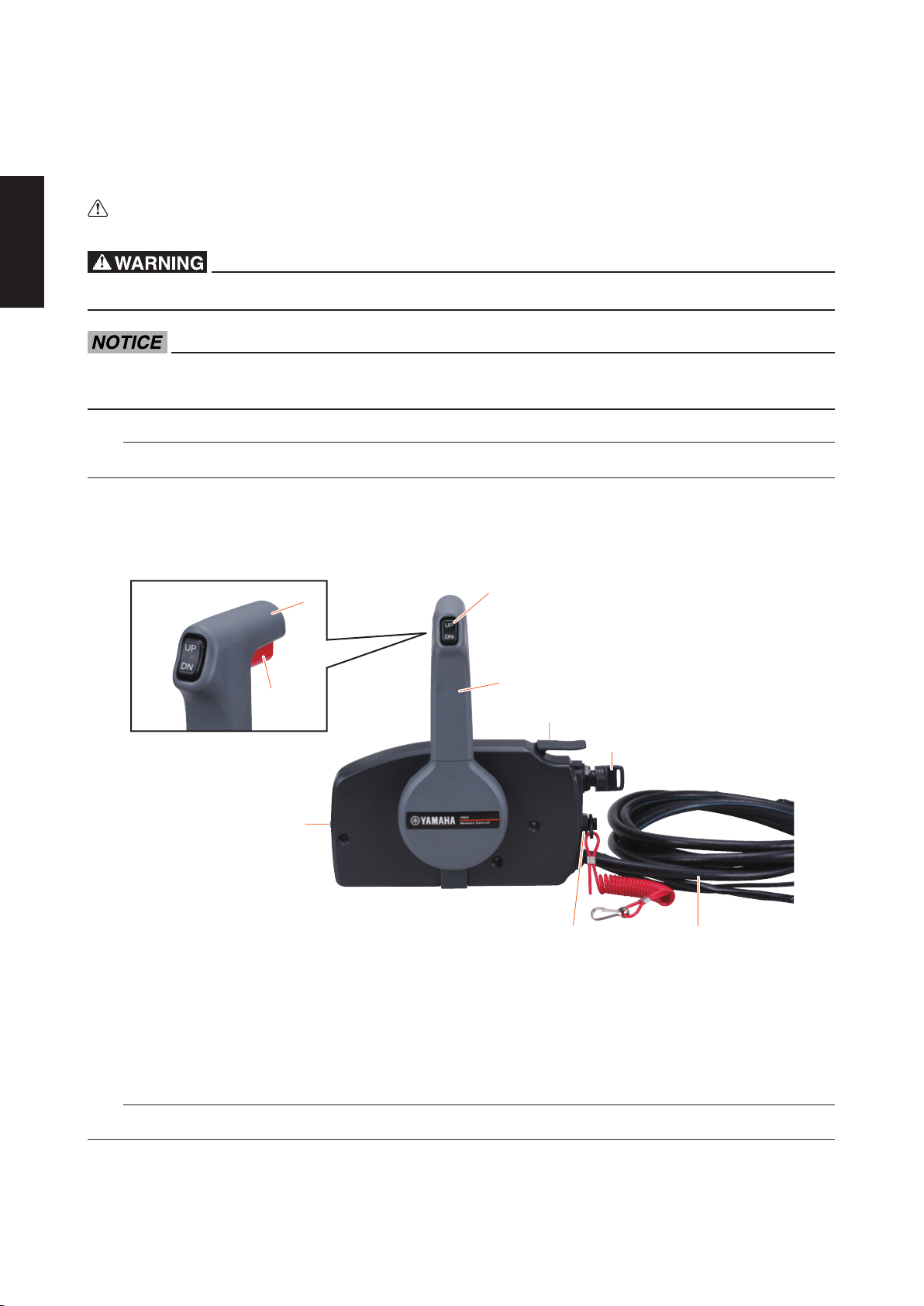
1. MAIN COMPONENTS
2
1. Grip
2. Neutral interlock trigger
3. Power trim and tilt switch*
4. Neutral throttle lever
5. Main switch/Choke switch*
1
3
9
4
5
8
6 7
6. Engine shut-off switch/Engine stop switch*
7. Wire harness (2, 7, or 10 pin)*
8. Throttle friction adjuster
9. Remote control lever
TIP
The mark (*) differs on the remote control specications.
2
Page 4
2. OPERATION
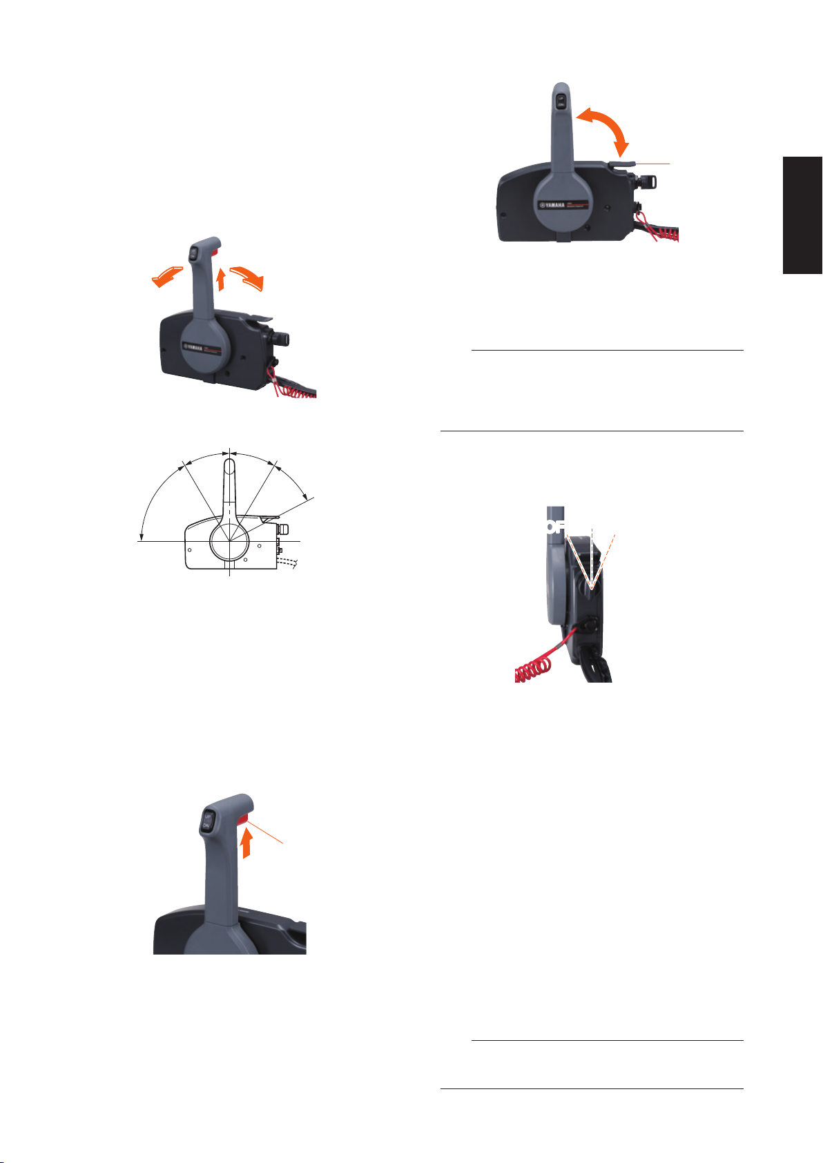
(1) Remote control lever
Moving the lever forward from the neutral position
engages forward gear. Pulling the lever back from
neutral engages reverse. The engine will continue to
run at idle until the lever is moved about 32° (a detent can be felt). Moving the lever farther opens the
throttle, and the engine will begin to accelerate.
F
F
2 3
5
6
R
N
1
R
44
5
6
2
3
1
1. Neutral throttle lever
2. Fully open
3. Fully closed
TIP
The neutral throttle lever will operate only when the
remote control lever is in neutral. The remote control
lever will operate only when the neutral throttle lever
is in the closed position.
(4) Main switch
The main switch controls the ignition system; its operation is described below.
ON
OFF
START
1. Neutral “N”/Fully closed
2. Forward “F” (about 32°)
3. Reverse “R” (about 32°)
4. Shift
5. Throttle
6. Fully open
(2) Neutral interlock trigger
Keeps the remote control lever in the neutral position. To shift in gear position, first pull the neutral
interlock trigger up and move the lever.
1
1. Neutral interlock trigger
(3) Neutral throttle lever
To open the throttle without shifting into either forward or reverse, put the remote control lever in the
neutral position and lift the neutral throttle lever.
“OFF” (off)
•
With the main switch in the “OFF” (off) position,
the engine stops. (The key can be removed.)
“ON” (on)
•
With the main switch in the “ON” (on) position, the
accessory can be used. (The key cannot be removed.)
“START” (start)
•
With the main switch in the “START” (start) position, the star ter motor turns to start the engine.
When the key is released, it returns automatically
to the “ON” (on) position.
(5) Choke switch
To activate the choke system, press in the main
switch while the key is turned to the “ON” (on) or
“OFF” (off) position. The choke system will activate
and supply the rich fuel mixture required to start the
cold engine. (When the key is released, the choke
system will deactivate automatically.)
TIP
The choke switch functions, only with the engine
has the remote choke system.
3
Page 5
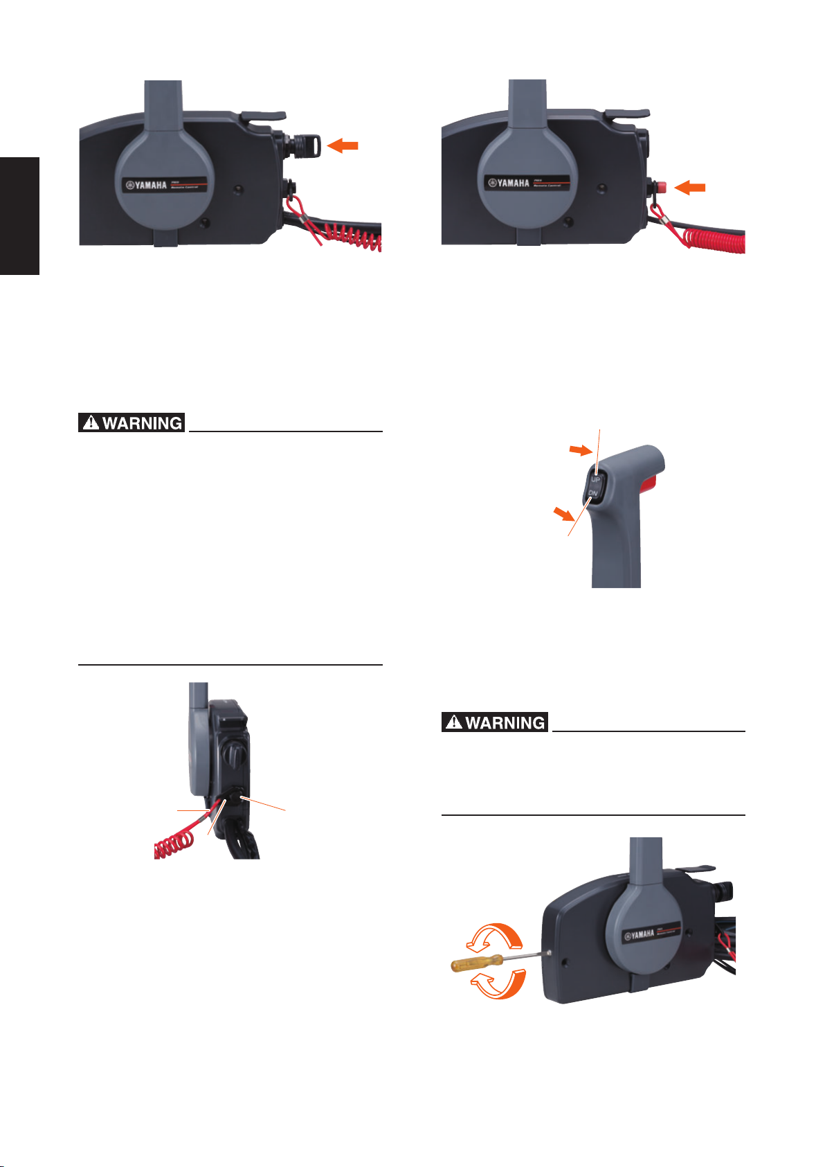
(6) Engine shut-off cord (lanyard) and clip
The clip must be attached to the engine shut-off
switch for the engine to run. The cord should be attached to a secure place on the operator’s clothing,
or arm or leg. Should the operator fall overboard or
leave the helm, the cord will pull out the clip, stopping ignition to the engine. This will prevent the boat
from running away under power.
(8) Power trim and tilt switch
The power trim and tilt system adjusts the outboard
motor angle in relation to the transom. Pushing the
switch “UP” (up) trims the outboard motor up, and
then tilts it up. Pushing the switch “DN” (down) tilts
the outboard motor down and trims it down. When
the switch is released, the outboard motor will stop
in its current position.
Attach the engine shut-off cord (lanyard) to a
•
secure place on your clothing, or your arm or
leg while operating.
Do not attach the cord to clothing that could
•
tear loose. Do not route the cord where it
could become entangled, preventing it from
functioning.
Avoid accidentally pulling the cord during nor-
•
mal operation. Loss of engine power means
the loss of most steering control. Also, without
engine power, the boat could slow rapidly. This
could cause people and objects in the boat to
be thrown forward.
1
3
2
UP
DN
(9) Throttle friction adjuster
A friction device provides adjustable resistance to
movement of the remote control lever, and can be
set according to operator preference. To increase
resistance, turn the adjuster clockwise. To decrease
resistance, turn the adjuster counterclockwise.
Do not over tighten the throttle friction adjuster.
If there is too much resistance, it could be difficult to move the remote control lever, which
could result in an accident.
1. Engine shut-off cord (lanyard)
2. Clip
3. Engine shut-off switch
(7) Engine stop button
The engine stop button (red) stops the engine when
the button is pushed.
4
Page 6
3. SAFETY FUNCTIONS
Depending on the combination of the remote control
box and engine, following function may not apply
some models. Refer to the Outboard motor Owner’s
Manual for further information.
(1) Warning buzzer
The buzzer will sound if the engine overheats, the
engine oil pressure drops (4
engine oil tank nearly empties (2-stroke engine)
which activated by the sensor installed on the engine.
If the warning buzzer sounds, turn off the engine
and check the cooling water inlet and engine oil
quantity. Then, return to nearest port immediately at low speeds. Please consult your Yamaha
dealer.
-stroke engine) or the
inner core) remote control cable to the 300 mm
(12 in) or less in diameter.
Bending the cable sharper than this limit could
cause shorten the life span of the cable and
increase resistance to the movement of the remote control lever.
A
BC
1
1. Loop
(2) Neutral switch
The neutral switch prevents the engine from starting with in-gear position. When the remote control
lever is in forward or reverse, the engine cannot be
started by operating the main switch.
4. REMOTE CONTROL BOX POSITIONING AND REMOTE CONTROL CABLE LENGTH
Incorrect selection or installation of a remote
control box may result in sudden and unexpected loss of control, thus resulting in a serious accident. Please consult your Yamaha dealer.
(1) Remote control box position
The remote control box should be set in a position
which it does not obstruct the operations of the remote control lever and switches.
Make sure there is no obstruction on the path of the
remote control cables.
(2) Remote control cable length
Measure the distance from the “A” point (the center
of the remote control box) to the “C” point (the center
of the engine) through the “B” point (a corner of the
transom). Add 1 m (3 ft) length to make a loop in the
motor-well.
Position the remote control cables and check that
they are long enough. Connect the cables to the engine and make sure they do not interfere with other
components when the steering is fully turned and
the engine is fully tilted up.
Do not bend the 33C type (standard inner core)
remote control cable to the 400 mm (16 in) or
less in diameter, and the 33HPC type (low-friction
5. INSTALLING THE REMOTE CONTROL CABLES
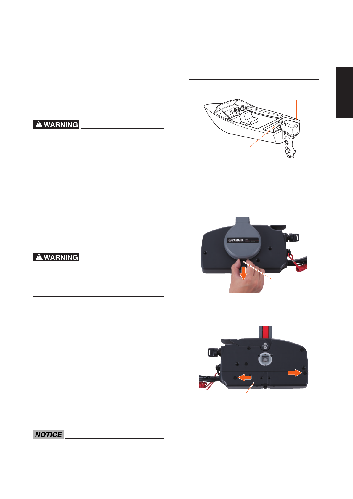
1) Pinch the wire cover with your ngers and pull it
out to remove.
1
1. Wire cover
2) Remove the two screws, and remove the back
panel (lower).
1
1. Back panel (lower)
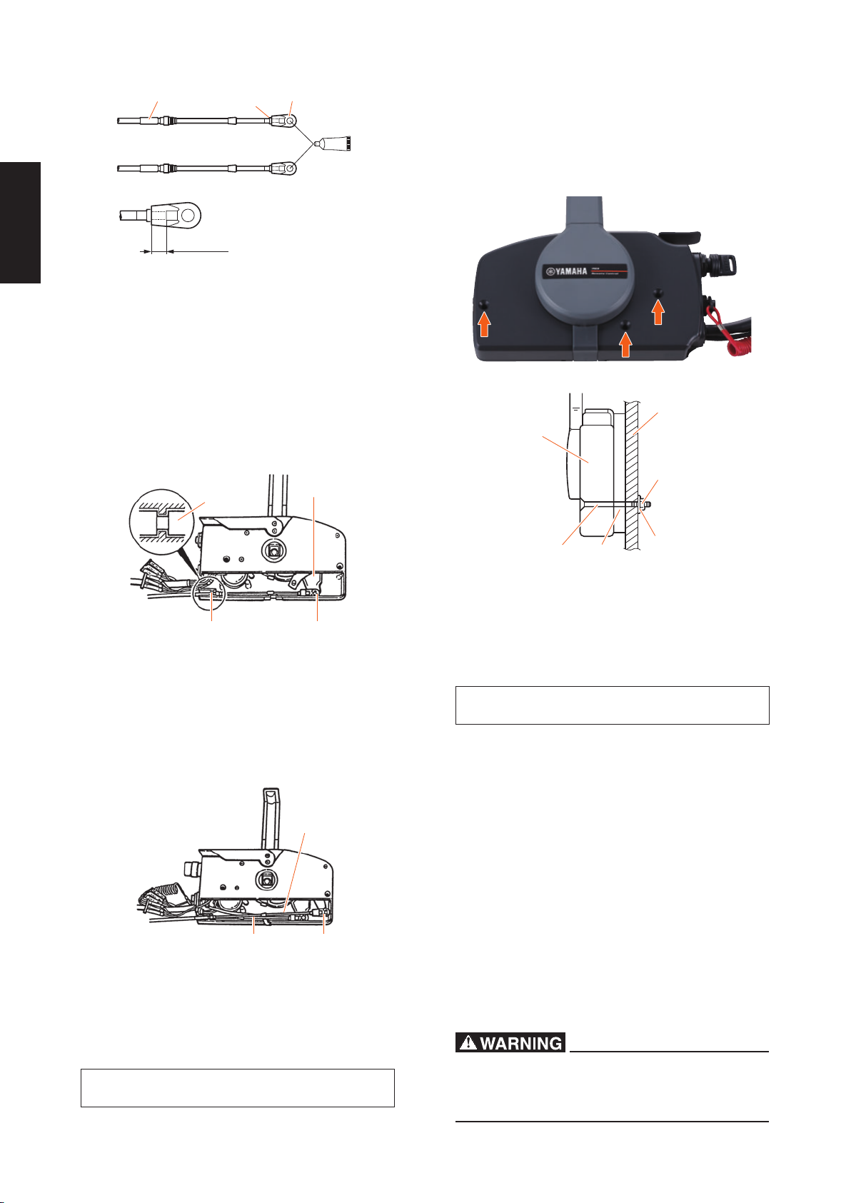
3) Screw in the cable joints about 11 mm (0.4 in)
over the ends of the remote control cables,
and tighten the locknuts. Before installing the
cable joints, apply the water-resistance grease
(Yamaha Grease A) to the holes in the cable
joints.
5
Page 7
1
2
3
A
4
11mm (0.4 in)
1. Remote control cable
2. Locknut
3. Cable joint
4. Apply grease
4) Insert the remote control cable outer groove
for shifting into the housing clamp so that the
groove on its end fits over the ridge in the
clamp. Fit the cable joint over the pin on the end
of the shift arm, and secure it with the circlip.
5) Fit the original grommet in the clamp groove.
8) After connecting the remote control cables,
install the remote control box in the previously
determined position using the ttings. It will be
easy to install the remote control box if the premounting holes are marked beforehand using
the remote control box mounting holes.
6
1
3
2
14
1. Circlip
2. Shift arm
3. Grommet
4. Clamp groove
6)
Connect the remote control cable for the throt-
tle to the throttle arm in the same manner.
1
32
1. Remote control cable for throttle
2. Remote control cable for shifting
3. Circlip
7) Secure the back panel (lower) with the two
screws, and install the wire cover.
Back panel screw:
4 Nm, 0.4 kgf-m, 3.0 lb-ft
5
2
3
1. Remote control box
2. Screw
3. Spacer
4. Washer
5. Nut
6. Bulwark
Remote control box screw:
7 Nm, 0.7 kgf-m, 5.2 lb-ft
9) Refer to the applicable service manual and connect the remote control cables both for shifting
and throttle and wire harnesses to the engine.
When connecting, set the remote control lever
to the neutral position, and place the neutral
throttle lever in the fully closed position.
10) By operating the remote control lever few times,
check that when the lever is turned to forward
or reverse until it stops once (about 32°), the
gear shifts, and that when the lever is turned
further from this position to forward, the throttle fully opens. Next, make sure that when the
remote control lever is returned to the neutral
position, the throttle on the engine side is completely closed. If not fully closed, adjust the
positions of cable joints on the engine side, and
install them again.
The cable joints on the engine side must be
screwed in at least 8 mm (0.3 in) over the remote
control cables.
4
6
Page 8
6. CHANGE IN THE REMOTE
7
2 3
CONTROL LEVER POSITION
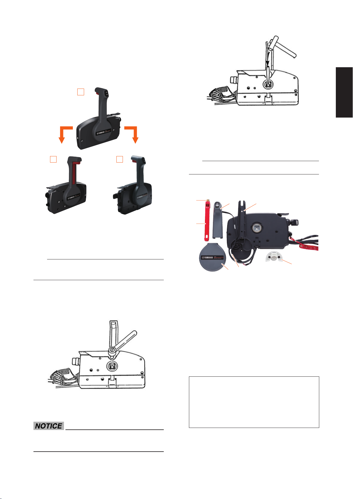
This remote control box can change the remote control lever to the opposite position as shown below.
Besides, the grip can be changed to reverse. Follow
the procedure for repositioning.
A
4) Remove the remote control lever cover and remove the power trim and tilt switch leads from
the guide of the remote control lever.
5) Remove two screws and neutral lock holder.
6) Remove the screw and neutral interlock trigger.
B C
A. Original remote control lever position
B. Repositioned remote control lever and grip
C. Repositioned remote control lever
TIP
Steps 4), 6) to 9), 11) to 13) are not necessary if the
grip is not repositioned.
1) Pinch the wire cover with your ngers, and pull
it out to remove.
2) Using a socket wrench (12 mm), loosen the
bolt.
TIP
Make sure not to drop the spring.
7) Remove two screws and pull the grip from remote control lever.
16
5
4
1. Remote control lever
2. Remote control lever cover
3. Power trim and tilt switch leads
4. Neutral lock holder
5. Neutral interlock trigger
6. Grip
7. Spring
8) Reverse the grip and put it into the remote control lever and secure it with two screws.
9) Install the neutral interlock trigger with the
screw.
10) Reverse the remote control box and secure the
neutral lock holder with two screws.
Screws
Grip screw:
3 Nm, 0.3 kgf-m, 2.2 lb-ft
3) Place a punch on the bolt head, and by tapping
it with a hammer, remove the remote control
lever from the remote control box.
Use care not to damage power tri m and t ilt
switch leads.
Neutral interlock trigger screw:
3 Nm, 0.3 kgf-m, 2.2 lb-ft
Neutral lock holder screw:
4 Nm, 0.4 kgf-m, 3.0 lb-ft
11) Align the power trim and tilt switch leads at the
upper taped position with the end of the grip,
and the center taped position with the exit of
the spiral slit.
7
Page 9
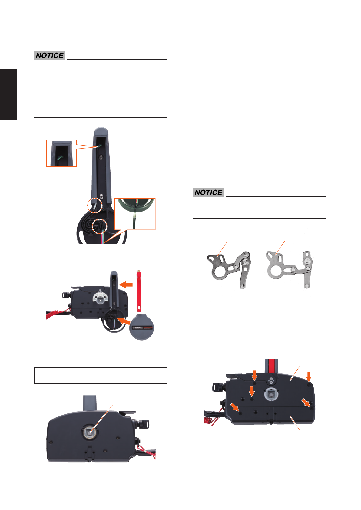
12) Install the power trim and tilt switch leads between those positioning tapes into the spiral slit.
Make sure not to pinch the power trim and tilt
•
switch leads between the remote control lever
and the grip.
Make sure that the plate located at the lower
•
end of the power trim and tilt switch leads is
facing upward and that the power trim and tilt
switch leads are not twisted.
TIP
Make sure that the excess portion of the power trim
and tilt switch leads are put in the box so that the
leads are not twisted or slackened while installing
the wire cover.
7. CHANGE FROM THE PUSH-TOOPEN THROTTLE TYPE TO THE
PULL-TO-OPEN THROTTLE TYPE
The remote control box permits to change from the
push-to-open throttle type to the pull-to-open throttle
type by changing some inner parts and their positions.
This instructions explain the procedure for changing
from the push-to-open throttle type to the pull-toopen throttle type. Therefore, if it has to be changed
from the pull-to-open type to the push-to-open type,
simply reverse the procedure.
When reinstalling parts, apply the water-resistant grease (Yamaha Grease A) to moving parts.
13) Install the neutral interlock trigger and remote
control lever cover to the remote control lever.
14) Install the remote control lever, and secure it
with the bolt and washer from the back side.
Remote control lever bolt:
13 Nm, 1.3 kgf-m, 9.6 lb-ft
1
1
1. Throttle arm for pull-to-open throttle type
2. Throttle arm for push-to-open throttle type
1) Pinch the wire cover with your ngers and pull it
out to remove.
2) Remove the ve screws, and remove both rear
housing (upper) and back panel (lower).
2
1
1. Bolt
2
1. Rear housing (upper)
2. Back panel (lower)
8
Page 10
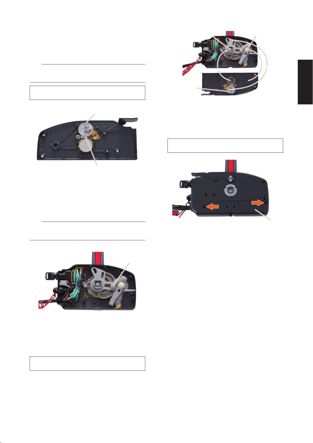
3) Remove the two screws holding the neutral
throttle lever, and remove the throttle drum. Rotate the drum 180°, and install it again with the
same screws.
TIP
Use care so that the roller does not jump out due to
spring force.
1
2
Throttle drum screw:
4 Nm, 0.4 kgf-m, 3.0 lb-ft
1
2
1. Throttle drum
2. Roller
4) Remove the throttle arm for the push-to-open
throttle type, and install the throttle arm for the
pull-to-open throttle type.
TIP
Use care not to lose the cam roller attached to the
throttle arm.
3
1. Main shaft
2. Throttle arm shaft
3. Drive pin
6) Secure the back panel (lower) with the two
screws, and install the wire cover.
Back panel screw:
4 Nm, 0.4 kgf-m, 3.0 lb-ft
1
1. Back panel (lower)
1
1. Cam roller
5) Align the main shaft and throttle arm shaft with
the grooves, and align the drive pin with the
slot, and secure the rear housing (upper) with
the three screws.
Rear housing screw:
4 Nm, 0.4 kgf-m, 3.0 lb-ft
9
Page 11
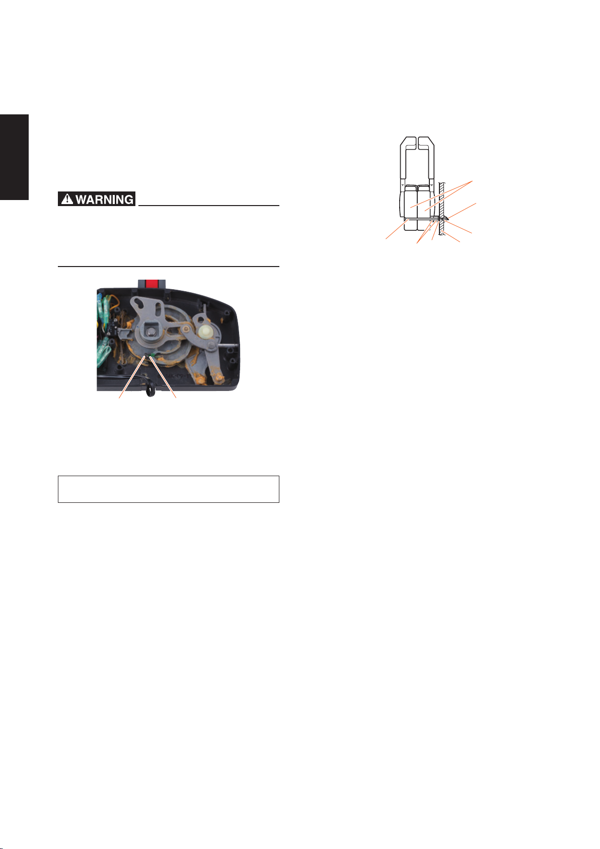
8. THROTTLE OPENING ADJUSTMENT AT REVERSE
1) Remove the wire cover, remove the screws,
and remove the rear housing (upper) and back
panel (lower).
2) Loosen the locknut, and adjust the throttle by
turning the adjusting bolt. Turning the adjusting bolt to the left makes the throttle opening
larger, and turning it to the right makes the
opening smaller.
If the reverse throttle opening is too large, it
may lead to an error in control operation. Set
the remote control lever so that it does not turn
more than 60° to the reverse.
9. REMOTE CONTROL BOX FOR TWIN-ENGINE
For twin-engine application, combine two remote
control boxes using the twin-attachment kit (P/N:
703-48290-01).
6
5
1
1. Screw
2. Spacer
3. Bulwark
4. Washer
5. Nut
6. Remote control box
2
4
4
3
1
1. Adjusting bolt
2. Locknut
3) After adjusting, tighten the adjusting bolt and
locknut.
Adjusting bolt, Locknut:
4 Nm, 0.4 kgf-m, 3.0 lb-ft
4) Install both rear housing (upper) and back panel (lower) with screw, and install the wire cover.
2
10. NOTE ON STORAGE
Follow the instructions below when storing the remote control box for a long period of time.
1) Remove the cable joints and apply water-resistant grease (Yamaha grease A) to the threaded
portion of the inner cable.
2) Also apply water-resistant grease (Yamaha
grease A) to inner parts of the remote control
box, particularly to contact surfaces of moving
parts. If any rust is found, remove it and apply
the grease (Yamaha grease A).
3) Avoid bending the cables into a loop as much
as possible. But if they have to be looped, the
loop diameter should be more than 1 m (40 in).
4) Select a dry place for storage.
10
Page 12

Printed in Japan
Dec. 2014 !
(E, F, ES, J)
Printed on recycled paper
Imprimé sur papier recyclé
Impreso en papel reciclado
再生紙を使用しています。
 Loading...