

Page 1
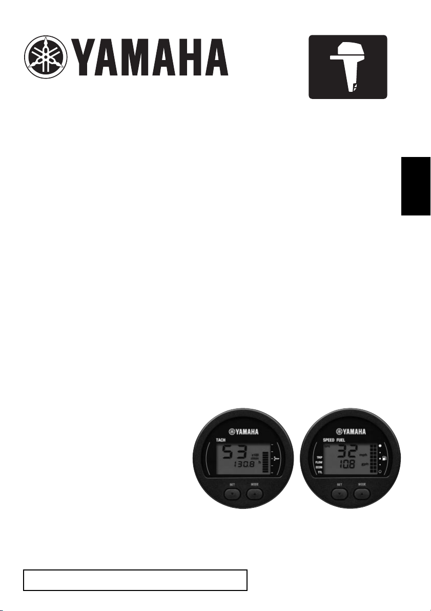
6Y8 MULTIFUNCTION
METERS
(ROUND STYLE)
OPERATION MANUAL
Read this manual carefully before operation.
LIT-18626-10-48
6Y8-2819W-70-E0
Page 2

Read this manual carefully before operating the meters. Keep this manual onboard in
a waterproof bag when boating.
Page 3
Important manual information
NOTICE
TIP:
6Y8 Multifunction Meters (Round style)
OPERATION MANUAL
©2013 by Yamaha Motor Co., LTD.
1st Edition, December 2013
All rights reserved.
Any reprinting or unauthorized use without the
written permission of Yamaha Motor Co., LTD.
is expressly prohibited.
Printed in Japan
To the owner
Thank you for selecting this product. This Operation Manual contains information needed for
proper operation. A thorough understanding of these simple instructions will help you obtain
maximum enjoyment from your new Yamaha. If you have any question about the operation
of the meters, please consult a Yamaha dealer.
In this Operation Manual particularly important information is distinguished in the following
ways.
This is the safety alert symbol. It is used to alert you to potential personal injury hazards.
Obey all safety messages that follow this symbol to avoid possible injury or death.
WARNING
A WARNING indicates a hazardous situation which, if not avoided, could result in
death or serious injury.
A NOTICE indicates special precautions that must be taken to avoid damage to the
outboard motor or other property.
A TIP provides key information to make procedures easier or clearer.
Information about the Operation Manual
Yamaha continually seeks advancements in product design and quality. Therefore, while this
manual contains the most current product information available at the time of printing, there
may be minor discrepancies between the product and this manual.
Page 4

The 6Y8 Multifunction Meters (Round style)
enables the display of information through
digital communication with the engine.
The operations of the set button and the
mode button are described in this manual as
follows.
Optional parts such as the speed sensor,
cooling water pressure sensor, Multi sensor,
GPS, and Y-COP are described in this manual by assuming that the parts are installed
and set up on the outboard motor.
The 6Y8 Multifunction Meters (Round style)
described in this manual consists of the following.
• Tachometer unit
(Part No.: 6Y8-8350T-20)
• Speed & Fuel meter unit
(Part No.: 6Y8-83500-20)
The 6Y8 Multifunction Meters (Round style)
is compatible with the following outboard motors.
4-stroke models:
Fuel injection models only
2-stroke models:
HPDI models only
Button operations:
• [SET]
Press the [SET] button one time.
• [MODE]
Press the [MODE] button one time.
• [SET] or [MODE]
Press the [SET] button or the [MODE] button one time.
• [SET] (1 second)
Press the [SET] button for 1 second.
• [MODE] (4 seconds)
Press the [MODE] button for 4 seconds.
• [MODE] (1 second) (2 times)
Press the [MODE] button two times, 1 second each time.
• [SET] + [MODE]
Press the [SET] button and the [MODE]
button simultaneously.
• [SET] + [MODE] (1 second)
Press the [SET] button and the [MODE]
button simultaneously for 1 second.
Page 5

Table of contents
1. Tachometer unit...................... 1
Description ........................................... 2
Activating the meter.............................. 2
Periodic maintenance notification ........... 3
Tachometer .......................................... 3
Trim meter ............................................ 3
Multifunction display ............................. 4
Cooling water temperature display.......... 5
Battery voltage display ............................ 5
Total hour/Trip hour display .................... 6
Cooling water pressure display
(optional) ............................................. 7
Oil pressure display
(4-stroke models) ................................ 7
Oil level display (2-stroke models) .......... 8
Y-COP display (optional)......................... 8
Water detection warning ......................... 9
Engine trouble warning ........................... 9
Changing backlight settings ................. 9
Adjusting trolling speed ...................... 10
Changing settings (custom mode)...... 10
Switching to custom mode .................... 10
01 (resetting maintenance intervals) ..... 11
02 (setting trim angle) ........................... 11
03 (setting corresponding engine)......... 12
04 (system number reset [when connected
to digital electronic control])............... 13
2. Speed & Fuel meter unit .......14
Description..........................................15
Activating the meter............................ 15
Speedometer ...................................... 15
Fuel meter .......................................... 16
Multifunction display ........................... 17
Fuel flow display.................................... 18
Fuel economy display (optional) ........... 18
Total fuel consumption display.............. 18
Water surface temperature display
(optional) ........................................... 19
Depth display (optional) ........................ 19
Clock (optional) ..................................... 19
Trip display (optional)............................ 20
Changing backlight settings................ 20
Changing settings (custom mode) ...... 20
Switching to custom mode .................... 20
01 (setting displayed units) ................... 21
02 (setting fuel tank sensor).................. 23
03 (setting correction value).................. 23
3. Setting up the meters............25
Setting conditions ...............................25
Initial settings...................................... 25
Tachometer unit .................................... 25
Speed & Fuel meter unit ....................... 25
Page 6
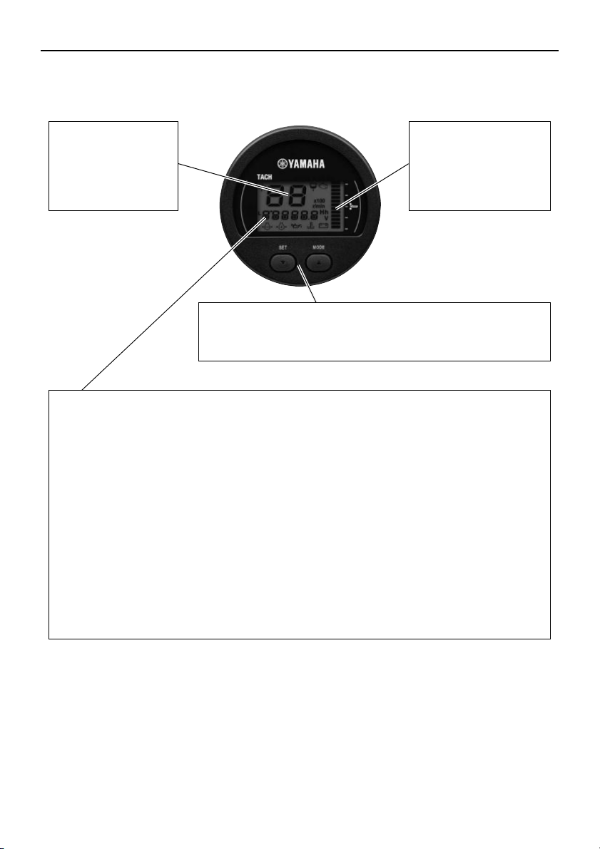
Tachometer unit
TIP:
Tachometer
The tachometer
shows the engine
revolutions per
minute. (page 3)
Trim meter
The trim meter shows
the trim angle of the
outboard motor in 13
levels. (page 3)
Multifunction display (page 4)
• Display of each engine information on the screen can be switched between numeric
values and graphic displays. In addition, when an engine malfunction occurs, each
icon blinks to warn of the malfunction.
Cooling water temperature display (page 5)
Battery voltage display (page 5)
Total hour/Trip hour display (page 6)
Cooling water pressure display (optional: cooling water pressure sensor
has been installed) (page 7)
Oil pressure display (4-stroke models) (page 7)
Oil level display (2-stroke models) (page 8)
Y-COP (Yamaha Customer Outboard Protection) display (optional) (page 8)
Water detection warning (page 9)
Engine trouble warning (page 9)
• Periodic maintenance intervals are notified.
Periodic maintenance notification (page 3)
Operation buttons for adjusting trolling speed
Use [SET] or [MODE] to adjust the trolling speed randomly.
(page 10)
1. Tachometer unit
Depending on the model of the outboard motor, some functions may not be compatible. For
detailed information, consult a Yamaha dealer.
1
Page 7
Tachometer unit
ab
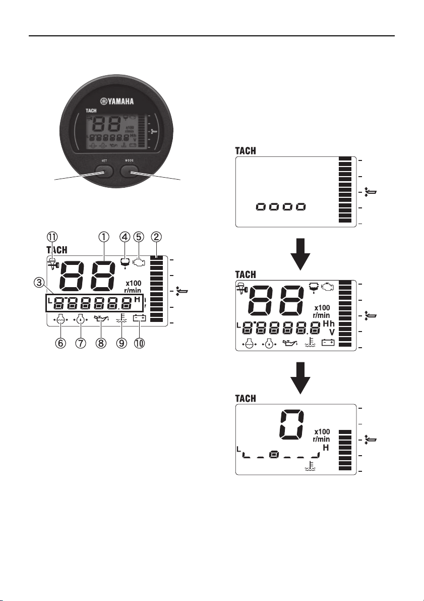
Description
a [SET] button
b [MODE] button
Activating the meter
When the engine start switch is turned to
ON, the meter is activated and “oooo” appears on the multifunction meter. Then, all
the displays come on and the display switches to the normal display after the total hour
display comes on.
a Tachometer
b Trim meter
c Multifunction display
d Water detection warning icon
e Engine trouble warning/maintenance
icon
f Cooling water pressure icon
g Oil pressure icon (4-stroke models)
h Oil level icon (2-stroke models)
i Cooling water temperature icon
j Battery voltage icon
k Y-COP icon
2
Page 8
Tachometer unit
TIP:
TIP:
When Y-COP is locked, after all the display
segments come on and then go off, the
Y-COP icon (y) remains on and the tachometer shows “–”.
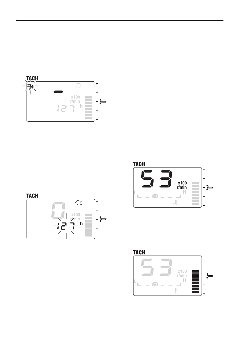
Periodic maintenance notification
When more than 100 hours have elapsed
since the previous maintenance period
(when the meter was reset), the engine trouble warning/maintenance icon comes on and
the elapsed time is displayed.
[SET] or [MODE]: To return to the normal
display.
• The elapsed time blinks every time the engine is started until it is reset. In addition,
the engine trouble warning/maintenance
icon (m) remains on until it is reset.
• When the hours of engine operation exceed 100 hours and the periodic maintenance notification is activated, consult an
authorized Yamaha dealer for periodical
maintenance.
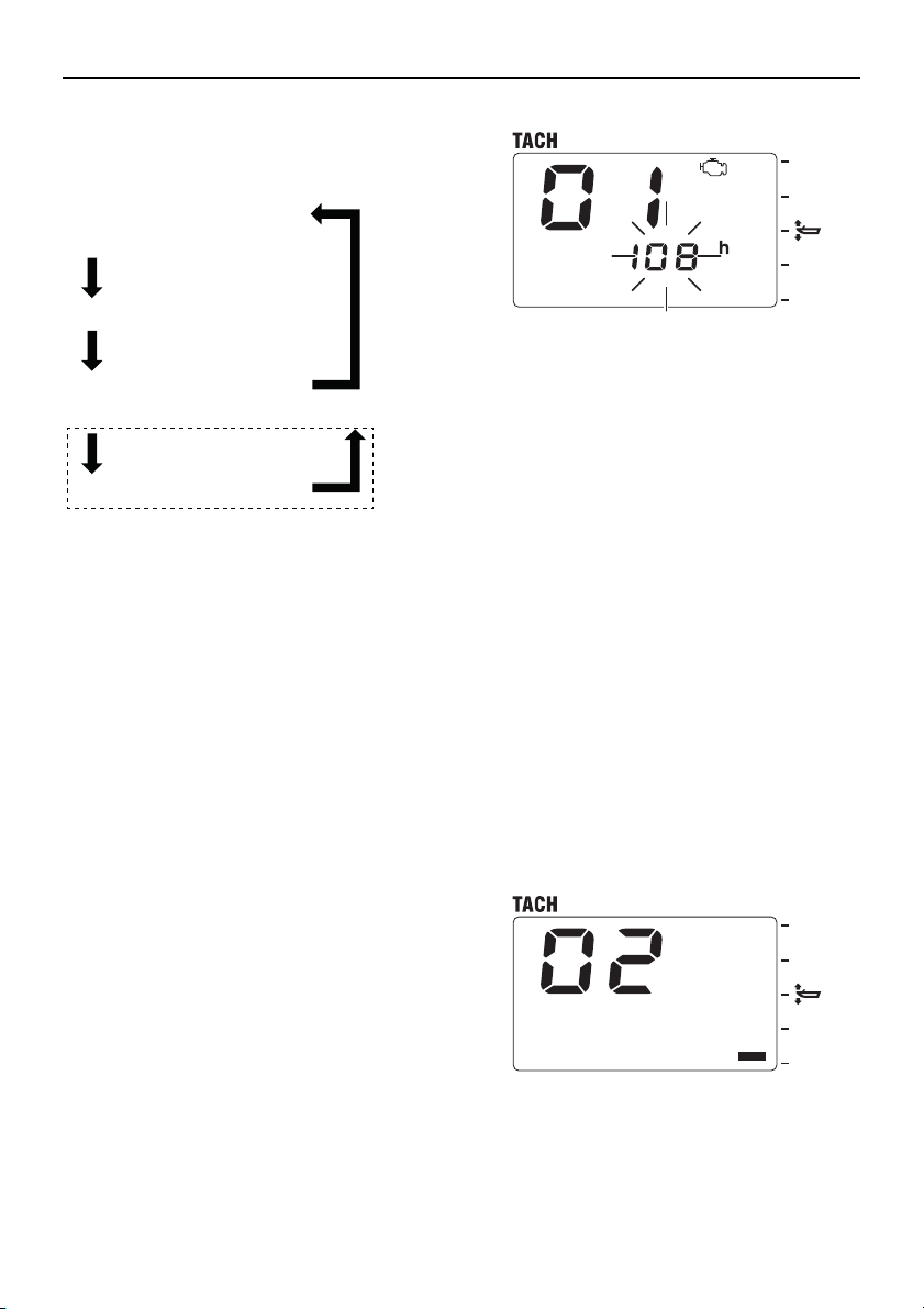
• To reset the maintenance period, see “01
(resetting maintenance intervals)” in
“Changing settings (custom mode)”.
Tachometer
The tachometer shows the engine revolutions per minute.
Trim meter
The trim meter shows the trim angle of the
outboard motor in 13 levels.
3
Page 9
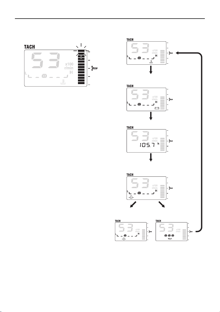
When the tilt angle of the outboard motor ex-
Cooling water
temperature
Battery voltage level/
Battery voltage value
Total hour/Trip hour
Cooling water pressure
(optional)
Oil pressure
(4-stroke)
Oil level
(2-stroke)
[MODE]
[MODE]
[MODE]
[MODE]
ceeds the trim range, the top segment blinks.
Multifunction display
The multifunction display shows various information using numeric values or graphics.
[MODE]: To switch between the displays.
Tachometer unit
[MODE]
When the engine start switch is turned to
OFF, the last display shown is shown first
when the engine start switch is turned to ON
again (by default, battery voltage level/value
is displayed).
4
Page 10
Tachometer unit
TIP:
NOTICE
TIP:
Battery voltage level
Battery voltage value
[SET] [SET]
• If an optional sensor is not connected to
the meter, the cooling water pressure will
not be displayed.
• Display of oil pressure (4-stroke) is only
available on F150 or larger models.
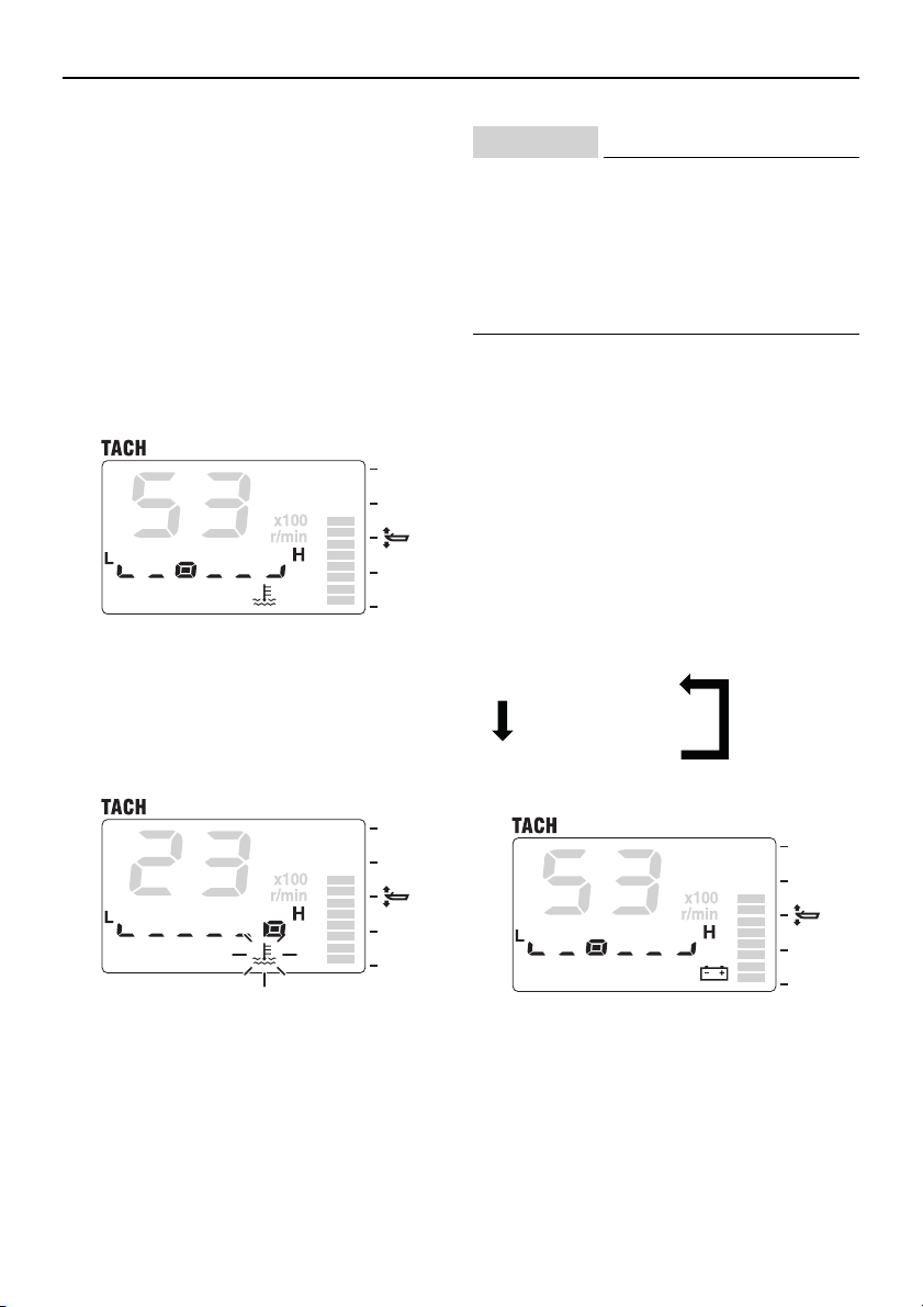
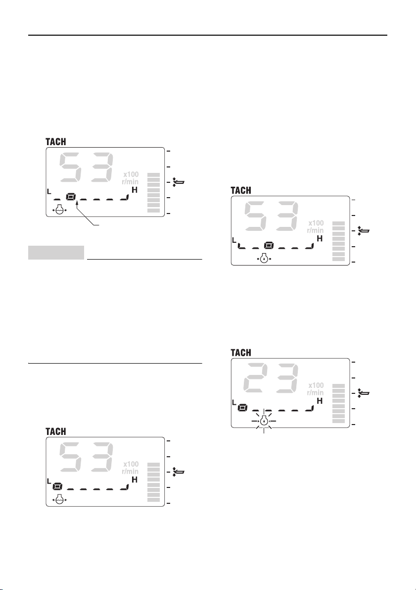
Cooling water temperature display
The cooling water temperature icon (t)
comes on and the cooling water temperature
is shown in 6 levels.
When the engine overheats, the cooling water temperature icon (t) blinks to warn of
the malfunction. At the same time, the engine speed will be limited and the buzzer
sounds.
• When the overheat warning comes on,
turn the engine off and check the cooling water inlet for clogs.
• If you cannot locate and correct the
cause, consult a Yamaha dealer immediately.
The cooling water temperature graphic display shows “L” for low and “H” for high.
Battery voltage display
The battery voltage icon (b) comes on
and the battery voltage of the engine is
shown in 6 levels or the voltage value is
shown.
[SET]: To switch between the display formats.
5
Page 11
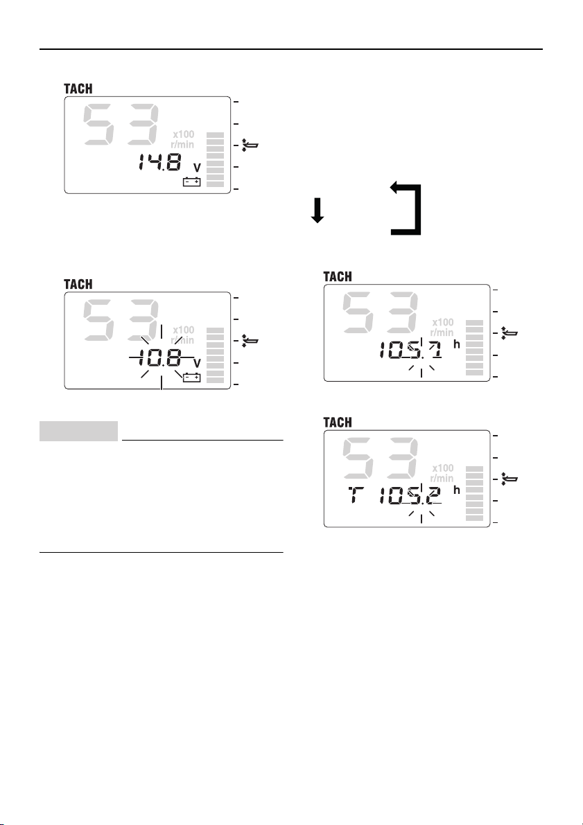
When the battery voltage decreases to less
NOTICE
TIP:
TIP:
Total hour
Trip hour (T)
[SET] [SET]
than 12 volts or increases to 16 volts or more
the voltage value blinks.
Tachometer unit
Total hour/Trip hour display
The total hour display shows the total hours
of engine operation and the trip hour display
shows the trip hours (T).
[SET]: To switch between the display formats.
• When the low battery voltage warning
comes on, check the battery and the
wiring.
• If you cannot locate and correct the
cause, consult a Yamaha dealer immediately.
The battery voltage graphic display shows
“L” for low and “H” for high.
[SET] + [MODE] (1 second): Press [SET]
and [MODE] for 1 second to reset the trip
hours (T).
• The total hours of engine operation cannot
be reset.
• The decimal point blinks when the hour
count is active.
6
Page 12
Tachometer unit
NOTICE
TIP:
10 psi (69 kPa)
Cooling water pressure display (optional)
The cooling water pressure icon (c) comes
on and the cooling water pressure is shown
in 6 levels.
If an optional water pressure sensor is not
connected, cooling water pressure will not be
displayed.
• If the cooling water pressure drops to
10 psi (69 kPa) or less during cruising
with the throttle fully open, turn the engine off and check the cooling water inlet for clogs.
• If you cannot locate and correct the
cause, consult a Yamaha dealer immediately.
• The cooling water pressure graphic display shows “L” for low and “H” for high.
• On some models, the buzzer function can
be deactivated using the [SET] or [MODE]
button.
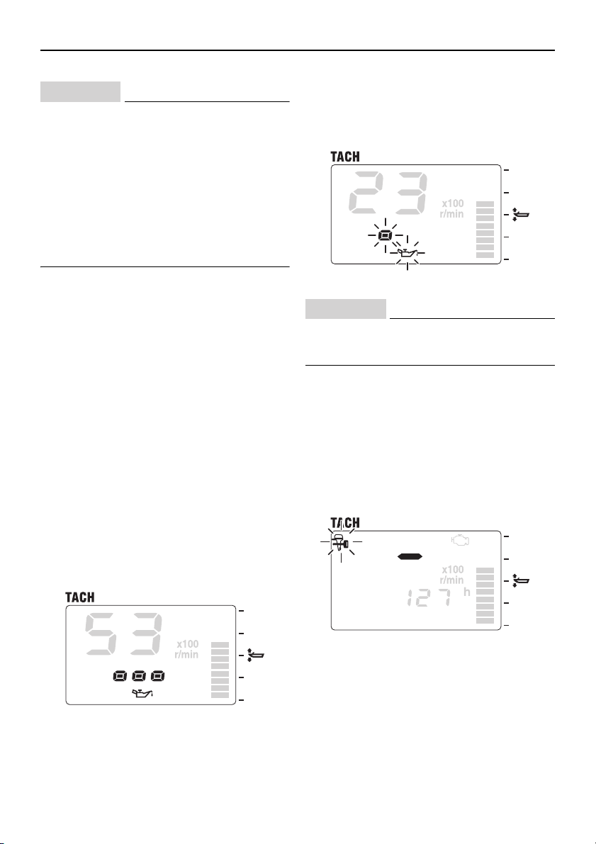
Oil pressure display (4-stroke models)
The oil pressure icon (p) comes on and the
engine oil pressure is shown in 6 levels.
When the engine oil pressure drops to less
than the specified value, the oil pressure icon
(p) blinks to warn of the malfunction. At the
same time, the engine speed will be limited
and the buzzer sounds.
If the cooling water pressure decreases, the
cooling water pressure icon (c) blinks and
the buzzer sounds to warn of the malfunction.
7
Page 13
NOTICE
• Do not operate the engine without en-
TIP:
NOTICE
gine oil. Severe engine damage can result.
• Check the oil level by following the procedure described in the Owner’s Manual of the outboard motor.
• If you cannot locate and correct the
cause, consult a Yamaha dealer immediately.
• The oil pressure graphic display shows “L”
for low and “H” for high.
• The low oil pressure warning does not display the engine oil level.
• On outboard motor models smaller than
F150, the oil pressure display may not be
available.
• Depending on the operating conditions
such as when the engine is operated at extremely low speeds, the oil pressure may
be shown as low even when the engine is
operating properly.
Tachometer unit
When the engine oil level is low, the oil level
icon (l) blinks to warn of the malfunction. At the same time, the engine speed will
be limited and the buzzer sounds.
Do not operate the engine without engine
oil. Severe engine damage can result.
Y-COP display (optional)
When Y-COP is locked, after all the display
segments come on and then go off, the
Y-COP icon (y) remains on and the tachometer shows “–”.
For the Y-COP unlocking procedure, see
Owner’s Manual of the outboard motor.
Oil level display (2-stroke models)
The oil level icon (l) comes on and the
engine oil level is shown in 3 levels.
8
Page 14
Tachometer unit
TIP:
TIP:
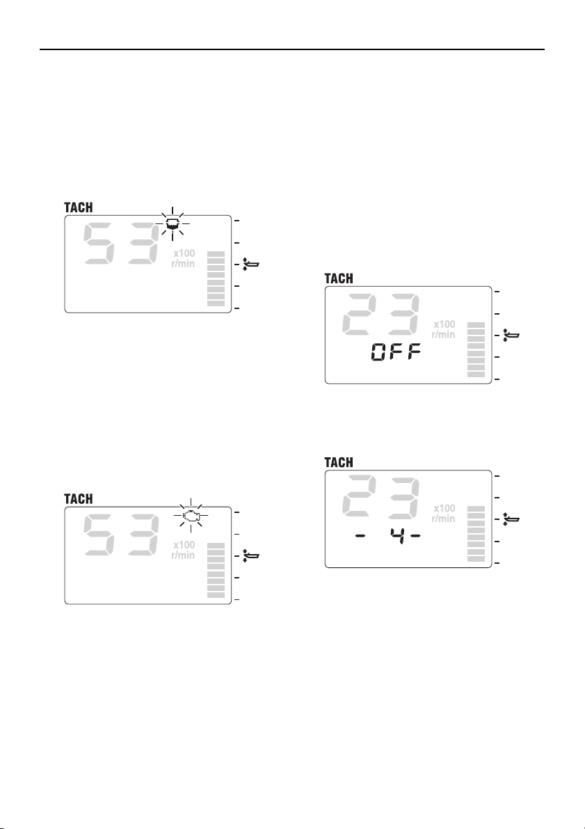
Water detection warning
When water has accumulated in the water
separator (fuel filter), the water detection
warning icon (w) blinks and the buzzer
sounds when the shift is in neutral to warn of
the malfunction. Consult a Yamaha dealer
immediately.
[SET] or [MODE]: To deactivate the buzzer.
Engine trouble warning
When engine trouble occurs, the engine
trouble warning/maintenance icon (m)
blinks to warn of the malfunction. Consult a
Yamaha dealer immediately.
Changing backlight settings
The backlight can be turned on or off, or the
brightness level of the backlight can be
changed for all meters synchronously.
1. [SET] + [MODE]: To activate the backlight mode.
2. [SET]: To switch between the backlight
on and off. When the backlight is on, the
brightness level is displayed. When the
backlight is off, “OFF” is displayed.
3. [MODE]: To switch between the five
brightness levels (1–5).
The engine trouble warning/maintenance
icon (m) flashes until the malfunction is repaired.
9
4. [SET] + [MODE]: To return to the normal
display.
Page 15
TIP:
• The backlight default settings are “OFF”
TIP:
and brightness level is 1.
• If no operations are carried out for 5 seconds or more, the display returns to the
normal display.
• The backlight settings can be changed
from all meters and all displays.
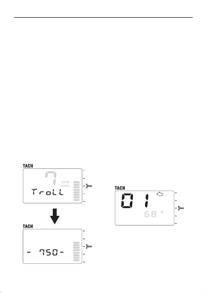
Adjusting trolling speed
The trolling speed can be adjusted randomly
by increasing or decreasing it approximately
50 r/min within the specified range depending on the model.
This function is not available for outboard
motors that are not equipped with the trolling
speed adjustment function.
1. [MODE] (1 second): After “TROLL” is dis-
played on the multifunction display, press
MODE for 1 second to activate the trolling speed setting mode.
Tachometer unit
2. [SET]: To decrease the engine speed.
3. [MODE]: To increase the engine speed.
4. [SET] (1 second): To return to the normal
display and to cancel the trolling speed
setting mode.
• The trolling speed setting mode is also
canceled when the engine is turned off or
when the engine speed exceeds
3,000 r/min.
• When warming up a cold engine, the troll-
ing speed cannot be decreased below the
engine high idle speed during warm up.
Changing settings (custom mode)
Switching to custom mode
In the custom mode, the meter function settings can be changed. Each setting function
number is shown in the tachometer display.
1. Turn the engine off and the engine start
switch to ON.
2. [MODE] (4 seconds): To activate the
custom mode.
10
Page 16
Tachometer unit
TIP:
TIP:
01 (resetting maintenance intervals)
[MODE] (1 sec.)
02 (setting trim angle)
[MODE] (1 sec.)
03 (setting corresponding
engine)
[MODE] (1 sec.)
04 (system number reset)
Only when connected to digital electronic
remote control.
[MODE]
(1 sec.)
3. [MODE] (1 second): To switch between
the setting function numbers and to
switch to the change settings display.
3. [SET] + [MODE] (1 second): To reset the
elapsed time to “0h” and return to the normal display.
Press the [SET] button for 1 second from
step 2 to cancel the resetting of the elapsed
time and return to the normal display.
4. Change each setting and return to the
normal display. To change the settings,
see the corresponding sections for each
setting function.
If no operations are carried out for 30 seconds or more or if the engine is started, the
settings will not be applied and the display
returns to the normal display.
01 (resetting maintenance intervals)
The elapsed time from the previous maintenance interval (when the meter was reset)
can be reset.
1. Turn the engine off and the engine start
switch to ON.
2. [MODE] (4 seconds): To activate the
custom mode and to switch to the resetting display.
11
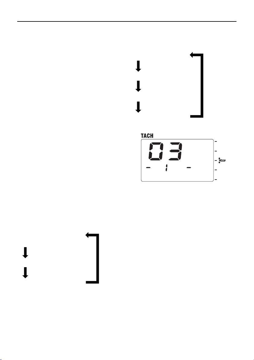
02 (setting trim angle)
The trim angle can be set to zero. Fully trim
the outboard motor down.
1. Turn the engine off and the engine start
switch to ON.
2. [MODE] (4 seconds): To activate the
custom mode.
3. [MODE] (1 second): To switch between
the setting function numbers and to
switch to the zero adjustment display.
Page 17
Tachometer unit
TIP:
TIP:
01 (resetting maintenance
intervals)
[MODE] (1 sec.)
02 (setting trim angle)
[MODE] (1 sec.)
03 (setting corresponding engine)
[MODE]
(1 sec.)
-1- (engine number 1)
[MODE]
-2- (engine number 2)
[MODE]
-3- (engine number 3)
[MODE]
-4- (engine number 4)
[MODE]
4. [SET] + [MODE] (1 second): To adjust
the trim angle to zero using the current
trim position as the standard value and
return to the normal display.
Press the [SET] button for 1 second from
step 3 to cancel the adjustment of the trim
angle to zero and return to the normal display.
03 (setting corresponding engine)
The engine that corresponds to this meter
can be selected, in case of multi-engine applications. The port outboard motor is set to
“-1- (engine number 1)” and the starboard
outboard motor is set to “-2- (engine number
2).”
1. Turn the engine off and the engine start
switch to ON.
2. [MODE] (4 seconds): To activate the
custom mode.
3. [MODE] (1 second) (2 times): To switch
between the setting function numbers
and to switch to the change settings display.
4. [MODE]: To switch between the displayed engine numbers.
5. [SET] (1 second): To change the corresponding engine and return to the normal
display.
By default, the meters are set to “-1- (engine
number 1).”
12
Page 18

Tachometer unit
TIP:
01 (resetting maintenance
intervals)
[MODE] (1 sec.)
02 (setting trim angle)
[MODE] (1 sec.)
03 (setting corresponding
engine)
[MODE] (1 sec.)
04 (system number reset)
[MODE]
(1 sec.)
04 (system number reset [when connected to digital electronic control])
The system number information stored on
the Gateway and meter that are connected
to the digital electronic control can be reset.
1. Turn off the engine, and then turn the engine start switch to ON.
2. [MODE] (4 seconds): To enter the custom mode.
3. [MODE] (1 second) (3 times)
4. Press to switch between the setting function numbers and to switch to the change
settings display.
5. [SET] + [MODE] (1 second): To reset the
system number and return to the normal
display.
In step 4, pressing [SET] for 1 second will
stop the resetting process and return to the
normal display.
13
Page 19
2. Speed & Fuel meter unit
TIP:
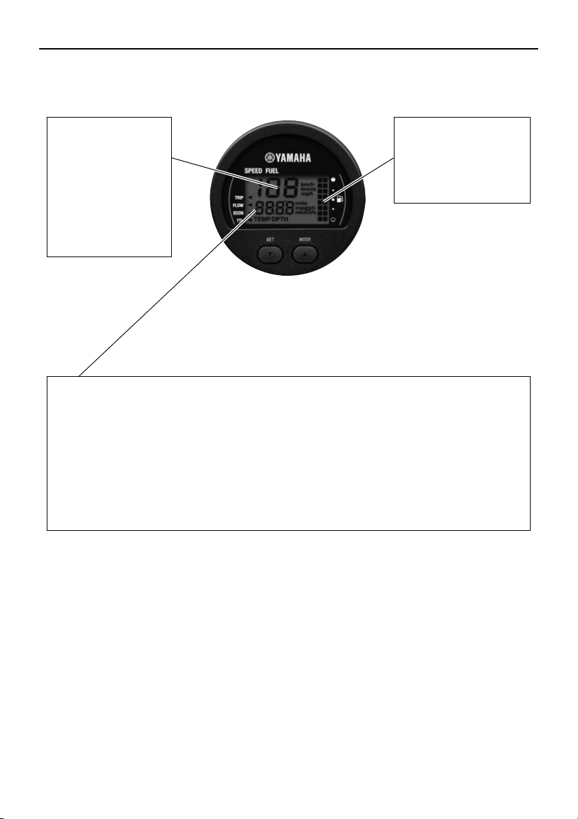
Speedometer
Shows the speed of
the boat. The
display unit can be
switched between
miles per hour
(mph), knots, or
kilometers per hour
(km/h). (page 15)
Fuel meter
The fuel meter shows
the remaining fuel
level in 8 levels.
(page 16)
Multifunction display (page 17)
• The following items can be selected to be shown on the display in numeric values.
Fuel flow display (page 18)
Fuel economy display (page 18)
Total fuel consumption display (page 18)
Water surface temperature display (optional) (page 19)
Depth display (optional) (page 19)
Clock (optional) (page 19)
Trip display (optional) (page 20)
Speed & Fuel meter unit
The gallons (g) displayed on this meter are US gallons, not imperial gallons. One US gallon
is equivalent to approximately 3.8 liters.
14
Page 20
Speed & Fuel meter unit
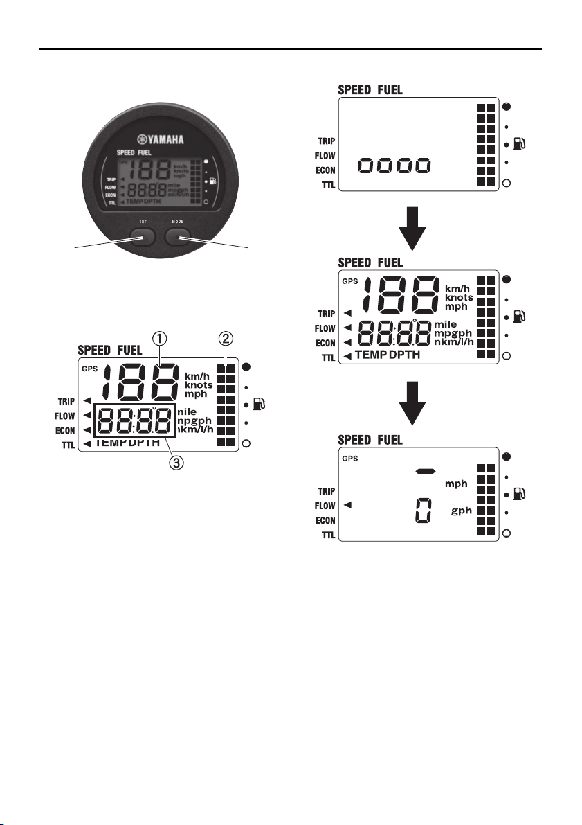
ab
Description
a [SET] button
b [MODE] button
a Speedometer
b Fuel meter
c Multifunction display
Activating the meter
When the engine start switch is turned to
ON, the meter is activated and “OOOO” appears on the multifunction meter. Then, all
the displays come on and the display switches to the normal display after a few seconds.
15
Speedometer
The speedometer shows the ground speed
or the water speed of the boat.
To display the ground speed, the GPS must
be connected to the meter. To display the
water speed, an optional sensor (speed sensor or Multi sensor) must be connected to the
meter.
Page 21
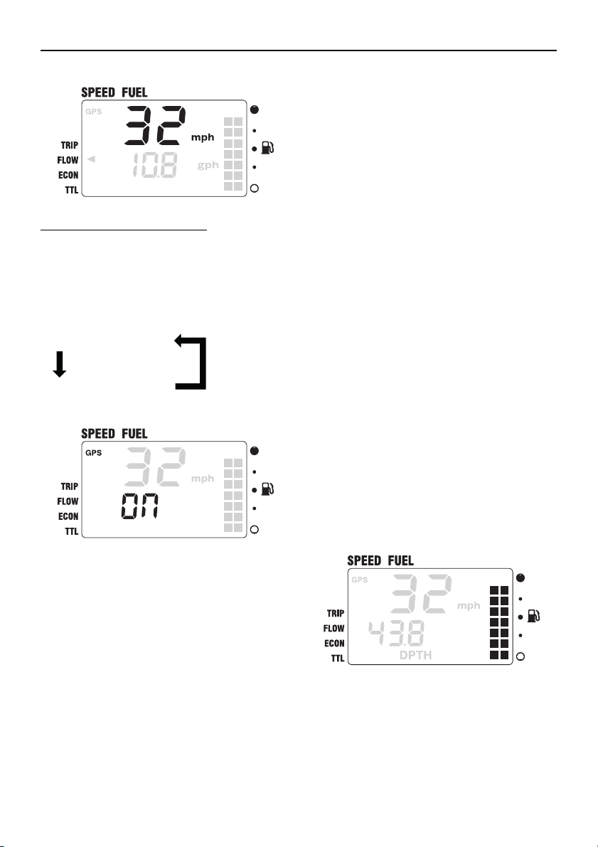
Switching the speed sensors:
TIP:
“On” (ground speed)
“OFF” (water speed)
[MODE] [MODE]
1. [SET] (4 seconds): To activate the speed
sensor setting mode.
2. [MODE]: To switch between the speed
sensor types.
Speed & Fuel meter unit
• If no operations are carried out for 30 seconds or more, the display returns to the
normal display.
• When signals from the GPS cannot be received even when the GPS function is on,
the GPS display goes off and the water
speed is displayed when an optional sensor is connected.
• Miles per hour (mph), knots, or kilometers
per hour (km/h) can be selected to be
shown on the speedometer display. To
change the displayed unit, see “01 (setting
displayed units)” in “Changing settings
(custom mode)”.
Fuel meter
The fuel meter shows the remaining fuel level in 8 levels and all the segments are displayed when the fuel tank is full. When the
fuel level is low, the last segment blinks.
When 2 fuel tanks are connected, each segment is divided into two, right and left, and remaining fuel level in each tank is displayed
individually (when only one tank is connected, both segments are synchronized).
3. [SET] (1 second): To set the speed sensor and return to the normal display.
16
Page 22
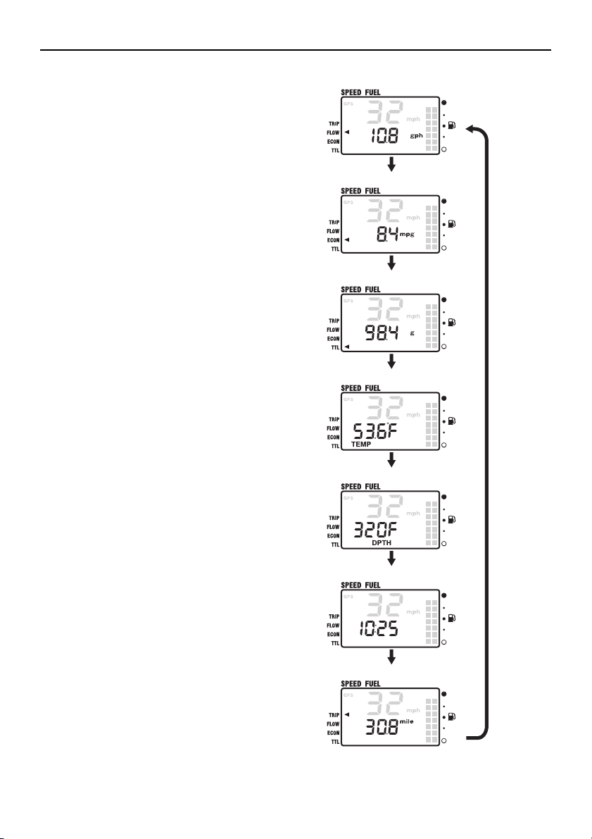
Speed & Fuel meter unit
TIP:
FLOW
[MODE]
ECON (optional)
[MODE]
TTL
[MODE]
TEMP (optional)
[MODE]
DPTH (optional)
[MODE]
Clock (optional)
[MODE]
TRIP (optional)
[MODE]
The fuel tank sensor setting can be changed
according to the fuel tank sensor type. To
change the fuel tank sensor setting, see “02
(setting fuel tank sensor)” in “Changing settings (custom mode)”.
Multifunction display
The multifunction display shows various information using numeric values.
[MODE]: To switch between the displays.
17
Page 23
When the engine start switch is turned to
TIP:
TIP:
TIP:
OFF, the last display shown is shown first
when the engine start switch is turned to ON
again.
• To change the various settings, see
“Changing settings (custom mode)”.
• If an optional sensor is not connected to
the meter, the corresponding display will
not be displayed.
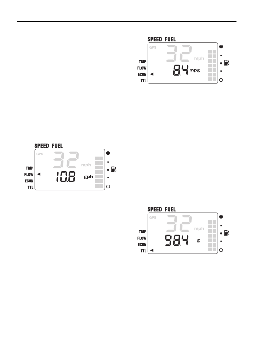
Fuel flow display
FLOW shows the total fuel consumption per
hour of all engines.
Speed & Fuel meter unit
• Fuel economy is affected by the type of
boat being operated and the operating
conditions, and it is constantly changing.
• Miles per gallon (mpg), nautical miles per
liter (nm/l), or kilometers per liter (km/l) can
be selected to be shown on the ECON display. To change the displayed unit, see “01
(setting displayed units)” in “Changing settings (custom mode)”.
Total fuel consumption display
TTL shows the total fuel consumption of all
engines.
Gallons per hour (gph) or liters per hour (l/h)
can be selected to be shown on the FLOW
display. To change the displayed unit, see
“01 (setting displayed units)” in “Changing
settings (custom mode)”.
Fuel economy display (optional)
ECON shows the distance traveled per unit
of fuel.
If an optional speed sensor, optional multi
sensor, or GPS is not connected, ECON will
not be displayed.
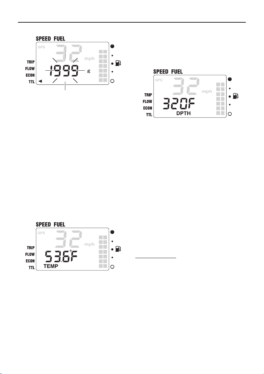
The TTL display cannot measure over 1,999
gallons or 1,999 liters. When the total fuel
consumption of all engines exceeds 1,999
gallons or 1,999 liters, the numeric value
blinks to indicate that the total fuel consumption cannot be measured.
18
Page 24
Speed & Fuel meter unit
TIP:
TIP:
TIP:
[SET] + [MODE] (1 second): To reset the
TTL display.
Gallons (g) or liters (l) can be selected to be
shown on the TTL display. To change the
displayed unit, see “01 (setting displayed
units)” in “Changing settings (custom
mode)”.
Water surface temperature display (optional)
TEMP shows the water surface temperature.
If an optional multi sensor is not connected,
TEMP (water surface temperature) will not
be displayed.
Depth display (optional)
DPTH shows the water depth.
If an optional multi sensor is not connected,
DPTH will not be displayed.
Feet (F) or meters (m) can be selected to be
shown on the DPTH display. To change the
displayed unit, see “01 (setting displayed
units)” in “Changing settings (custom
mode)”.
Clock (optional)
The clock shows the time in 12 hours. The local time is easily displayed by calculating the
longitude information received from the GPS
communication data. Set the time as necessary.
If a GPS is not connected, the clock will not
be displayed.
Fahrenheit (°F) or Celsius (°C) can be selected to be shown on the TEMP display. To
change the displayed unit, see “01 (setting
displayed units)” in “Changing settings (custom mode)”.
19
Setting the time:
1. [SET]: To activate the time setting mode
and switch to the time setting display.
Page 25
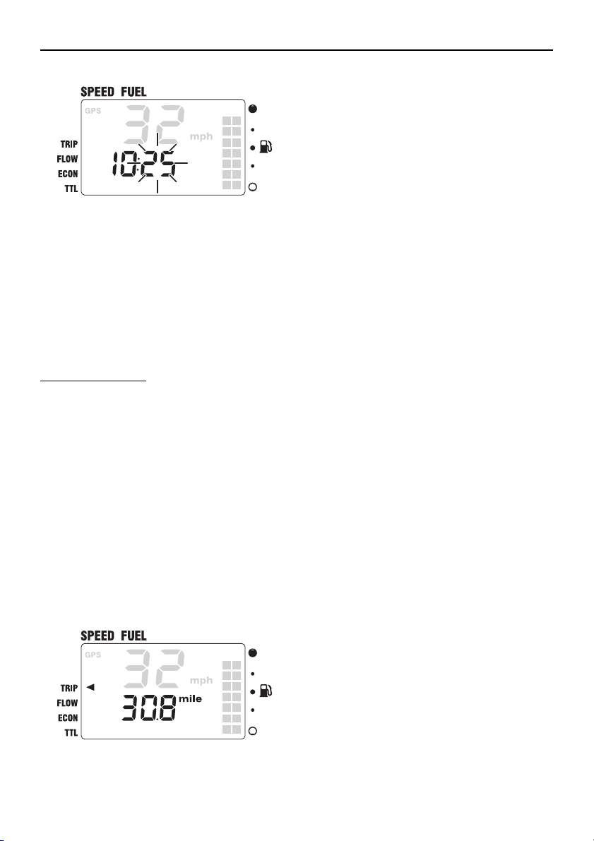
2. [MODE]: To change the minutes. Press
TIP:
TIP:
and hold to advance quickly.
3. [SET]: To set the hours.
4. [MODE]: To change the hours. Press
and hold to advance quickly.
5. [SET]: To set the time and return to the
normal display.
Resetting the time:
1. [SET]: To activate the time setting mode
and to switch to the time setting display.
2. [SET] + [MODE] (1 second): To reset the
time to “0:00” and return to the normal
display.
Trip display (optional)
TRIP shows the information from the speed
sensor, multi sensor, and GPS converted to
the distance traveled.
If an optional speed sensor, optional multi
sensor, or GPS is not connected, TRIP will
not be displayed.
Speed & Fuel meter unit
[SET] + [MODE] (1 second): To reset the
distance traveled.
• The distance traveled is affected by currents and other operating conditions and
may differ from the actual distance traveled.
• Miles (mile), nautical miles (nm), or kilometers (km) can be selected to be shown on
the TRIP display. To change the displayed
unit, see “01 (setting displayed units)” in
“Changing settings (custom mode)”.
Changing backlight settings
The backlight can be turned on or off, or the
brightness level of the backlight can be
changed for all meters synchronously.
The backlight setting procedure is the same
as that of the tachometer unit.
To change the backlight settings, see
“Changing backlight settings” in “1. Tachometer unit”.
Changing settings (custom mode)
Switching to custom mode
In the custom mode, the meter function settings can be changed. Each setting function
number is displayed in the speedometer display.
1. Turn the engine off and the engine start
switch to ON.
2. [MODE] (4 seconds): To activate the
custom mode.
20
Page 26
Speed & Fuel meter unit
TIP:
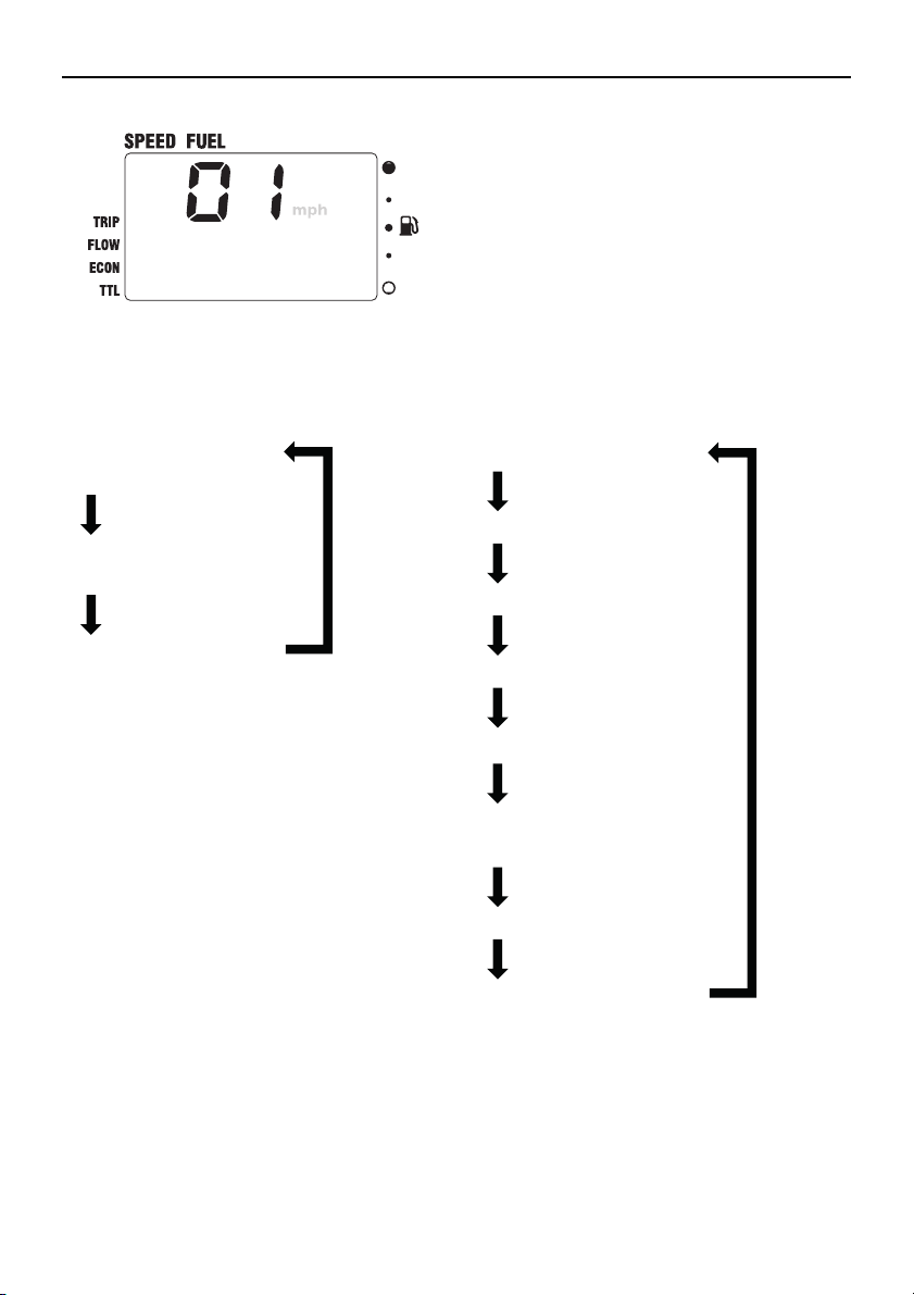
01 (setting displayed units)
[MODE] (1 sec.)
02 (setting fuel tank
sensor)
[MODE] (1 sec.)
03 (setting correction
value)
[MODE]
(1 sec.)
Speedometer
[MODE]
TRIP (trip)
[MODE]
FLOW (fuel flow)
[MODE]
ECON (fuel economy)
[MODE]
TTL (total fuel consumption)
[MODE]
TEMP (water surface
temperature)
[MODE]
DPTH (depth)
[MODE]
Clock
[MODE]
3. [MODE] (1 second): To switch between
the setting function numbers and to
switch to the change settings display.
01 (setting displayed units)
The units that are shown in each display can
be changed. The indicator of the selected
display blinks.
1. Turn the engine off and the engine start
switch to ON.
2. [MODE] (4 seconds): To activate the
custom mode and to switch to the change
settings display.
3. [MODE]: To switch between the displays.
4. Change each setting and return to the
normal display. To change the settings,
see the corresponding sections for each
setting function.
If no operations are carried out for 30 seconds or more or if the engine is started, the
settings will not be applied and the display
returns to the normal display.
21
Page 27
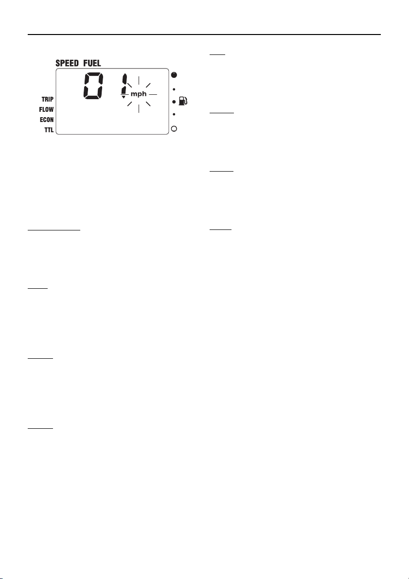
* In the display example, the speedometer is
TIP:
shown.
4. [SET]: To switch between the displays.
In addition, the display can be selected to
be shown or hidden.
Speedometer
The display unit can be switched between
miles per hour (mph), kilometers per hour
(km/h), or knots. The default setting is miles
per hour (mph).
TRIP
The display unit can be switched between
miles (mile), nautical miles (nm) or kilometers (km), or the display can be selected to
be shown or hidden. The default setting is
miles (mile).
FLOW
The display unit can be switched between
gallons per hour (gph) or liters per hour (l/h),
or the display can be selected to be shown or
hidden. The default setting is gallons per
hour (gph).
ECON
The display unit can be switched between
miles per gallon (mpg), nautical miles per liter (nm/l) or kilometers per liter (km/l), or the
display can be selected to be shown or hidden. The default setting is miles per gallon
(mpg).
Speed & Fuel meter unit
TTL
The display unit can be switched between
gallons (g) or liters (l), or the display can be
selected to be shown or hidden. The default
setting is gallons (g).
TEMP
The display unit can be switched between
Fahrenheit (°F) or Celsius (°C), or the display
can be selected to be shown or hidden. The
default setting is Fahrenheit (°F).
DPTH
The display unit can be switched between
feet (F) or meters (m), or the display can be
selected to be shown or hidden. The default
setting is feet (F).
Clock
By default, the clock is displayed. The clock
can be selected to be shown or hidden.
5. [SET] (1 second): To change the displayed unit and return to the normal display.
• When the speedometer unit settings are
changed, the TRIP, FLOW, ECON, TTL,
TEMP, and DPTH unit settings are collectively changed automatically. To change
the settings for each displayed unit individually, repeat steps 3 and 4.
• Press the [SET] and [MODE] buttons si-
multaneously for 1 second from step 2 to
reset all displayed units to the default settings.
22
Page 28
Speed & Fuel meter unit
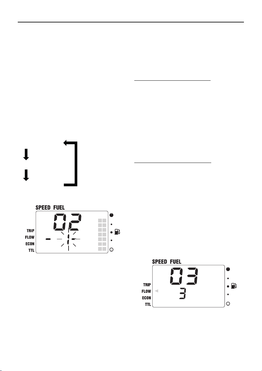
-1- (ABYC-US)
[MODE]
-2- (EUROPE)
[MODE]
-3- (YAMAHA)
[MODE]
02 (setting fuel tank sensor)
The fuel tank sensor type that is connected
to this meter can be selected.
1. Turn the engine off and the engine start
switch to ON.
2. [MODE] (4 seconds): To activate the
custom mode.
3. [MODE] (1 second): To switch between
the setting function numbers and to
switch to the change settings display.
4. [MODE]: To switch between the fuel tank
sensor types.
03 (setting correction value)
The displayed fuel flow value can be calibrated within –7 to +7 percent. The difference in
the fuel consumption display and the actual
fuel consumption is calibrated.
Checking the calibration value:
1. Operate the outboard motor on a full tank
of fuel.
2. After operating the outboard motor, fill
the fuel tank. Compare the amount of fuel
filled into the fuel tank with the fuel consumed shown on the fuel consumption
display and set the calibration value to
the difference if necessary.
Changing the calibration value:
1. Turn the engine off and the engine start
switch to ON.
2. [MODE] (4 seconds): To activate the
custom mode.
3. [MODE] (1 second) (2 times): To switch
between the setting function numbers
and to switch to the change settings display.
4. [MODE]: To switch between the calibration values.
5. [SET] (1 second): To change the fuel
tank sensor type and return to the normal
display.
23
5. [SET] (1 second): To change the calibration value and return to the normal display.
Page 29

TIP:
• The fuel flow display may differ depending
on the operating conditions.
• When the fuel flow calibration value is
changed, the FLOW, TTL, and ECON displays are shown calibrated.
Speed & Fuel meter unit
24
Page 30

Setting up the meters
3. Setting up the meters
Setting conditions
Meters may not function properly under the
following conditions:
1. When the meter is installed close to noise
sources such as generator, radio, or antenna wire. Make sure to keep a distance
of at least 30 cm (11.8 in) between the
meter and the noise source.
2. When the ambient temperature is high.
Please use the meter at temperature of
80 °C (176 °F) or lower.
3. When an incompatible aftermarket de-
vice is connected. Connect a device that
meets the setting requirements (such as
NMEA0183 compatible GPS).
Initial settings
Before operating the meter, be sure to
change the default settings as described below. For the setting procedures, see the corresponding setting procedure for each
meter.
Tachometer unit
03 (setting corresponding engine)
Select the engines compatible to this meter.
(page 12)
02 (setting trim angle)
Adjust the trim angle to zero. (page 11)
Speed & Fuel meter unit
02 (setting fuel tank sensor)
Set the meter according to the fuel tank sensor type. (page 23)
For detailed information, consult a Yamaha
dealer.
25
Page 31

Page 32

Printed in Japan
December 2013 - 5.0 x 1 ABE Printed on recycled paper
 Loading...