

Page 1
OWNER’S MANUAL
Read this manual carefully before operating this
outboard motor.
40V
50H
63B-28199-7N-E0
Page 2

EMU25053
Read this manual carefully before operating this outboard motor. Keep this
manual onboard in a waterproof bag when boating. This manual should stay
with the outboard motor if it is sold.
Page 3
Important manual information
TIP:
TIP:
EMU25108
To the owner
Thank you for selecting a Yamaha outboard
motor. This Owner’s Manual contains information needed for proper operation, maintenance and care. A thorough understanding
of these simple instructions will help you obtain maximum enjoyment from your new
Yamaha. If you have any question about the
operation or maintenance of your outboard
motor, please consult a Yamaha dealer.
In this Owner’s Manual particularly important
information is distinguished in the following
ways.
: This is the safety alert symbol. It is
used to alert you to potential personal injury
hazards. Obey all safety messages that follow this symbol to avoid possible injury or
death.
EWM00782
A WARNING indicates a hazardous situation which, if not avoided, could result in
death or serious injury.
ECM00702
A NOTICE indicates special precautions
that must be taken to avoid damage to the
outboard motor or other property.
there is any question concerning this manual, please consult your Yamaha dealer.
To ensure long product life, Yamaha recommends that you use the product and perform
the specified periodic inspections and maintenance by correctly following the instructions in the owner’s manual. Any damage
resulting from neglect of these instructions is
not covered by warranty.
Some countries have laws or regulations restricting users from taking the product out of
the country where it was purchased, and it
may be impossible to register the product in
the destination country. Additionally, the warranty may not apply in certain regions. When
planning to take the product to another country, consult the dealer where the product was
purchased for further information.
If the product was purchased used, please
consult your closest dealer for customer reregistration, and to be eligible for the specified services.
The 40VEO, 40VMHO, 50HETO and the
standard accessories are used as a base for
the explanations and illustrations in this manual. Therefore some items may not apply to
every model.
EMU25123
A TIP provides key information to make procedures easier or clearer.
Yamaha continually seeks advancements in
product design and quality. Therefore, while
this manual contains the most current product information available at the time of printing, there may be minor discrepancies
between your machine and this manual. If
40V, 50H
OWNER’S MANUAL
©2020 by Yamaha Motor Co., Ltd.
1st Edition, November 2019
All rights reserved.
Any reprinting or unauthorized use
without the written permission of
Yamaha Motor Co., Ltd.
is expressly prohibited.
Printed in Japan
Page 4

Table of contents
Safety information............................. 1
Outboard motor safety .....................1
Propeller .............................................. 1
Rotating parts ...................................... 1
Hot parts.............................................. 1
Electric shock ...................................... 1
Power trim and tilt................................ 1
Engine shut-off cord (lanyard) ............. 1
Gasoline .............................................. 2
Gasoline exposure and spills .............. 2
Carbon monoxide ................................ 2
Modifications ....................................... 2
Boating safety ..................................2
Alcohol and drugs................................ 2
Personal flotation devices (PFDs) ....... 2
People in the water.............................. 2
Passengers ......................................... 2
Overloading ......................................... 3
Avoid collisions.................................... 3
Collisions with floating or submerged
objects.............................................. 3
Weather............................................... 4
Passenger training .............................. 4
Boating safety publications.................. 4
Laws and regulations .......................... 4
General information .......................... 5
Identification numbers record...........5
Outboard motor serial number ............ 5
Key number ......................................... 5
EC Declaration of Conformity
(DoC)............................................. 5
CE Marking ......................................6
Read manuals and labels................. 7
Warning labels .................................... 7
Specifications and requirements... 10
Specifications ................................. 10
Installation requirements ................ 11
Boat horsepower rating ..................... 11
Mounting outboard motor .................. 11
Remote control requirements.........11
Battery requirements......................12
Battery specifications ........................ 12
Propeller selection ......................... 12
Start-in-gear protection .................. 13
Engine oil requirements ................. 13
Why Yamalube .................................. 13
Fuel requirements.......................... 13
Gasoline ............................................13
Muddy or acidic water.................... 14
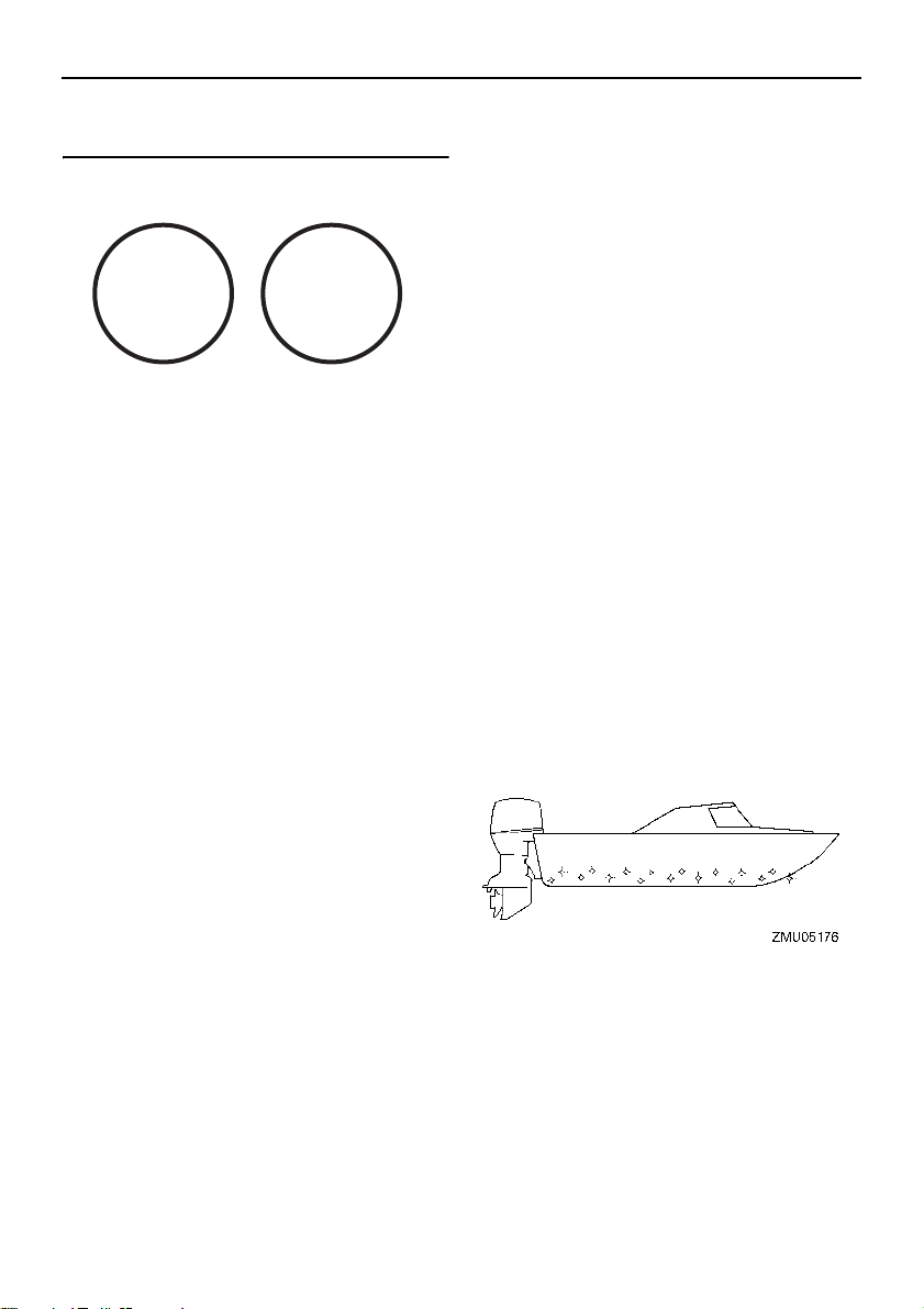
Anti-fouling paint ............................ 14
Outboard motor disposal
requirements............................... 14
Emergency equipment................... 15
Components .................................... 16
Components diagram..................... 16
Fuel tank............................................ 18
Fuel joint............................................ 19
Fuel gauge ........................................ 19
Fuel tank cap..................................... 19
Air vent screw.................................... 19
Remote control box ...........................19
Remote control lever .........................19
Neutral interlock trigger .....................20
Neutral throttle lever .......................... 20
Tiller handle ...................................... 20
Gear shift lever ................................. 20
Throttle grip ......................................20
Throttle indicator ............................... 21
Throttle friction adjuster..................... 21
Engine shut-off cord (lanyard) and
clip.................................................. 21
Engine stop button ........................... 22
Pull-type choke knob ......................... 22
Manual starter handle........................ 22
Main switch........................................ 23
Steering friction adjuster ................... 23
Steering friction adjuster.................... 23
Power trim and tilt switch on remote
control or tiller handle..................... 24
Power trim and tilt switch on bottom
cowling ........................................... 24
Trim tab with anode........................... 25
Trim rod (tilt pin) ................................25
Tilt lock mechanism........................... 25
Page 5

Table of contents
Tilt support lever for power trim and
tilt model......................................... 26
Tilt support lever for manual tilt
model ............................................. 26
Cowling lock lever(s) (turn type)........ 26
Alert indicator ................................... 27
Instruments and indicators ............ 28
Indicators ....................................... 28
Alert indicator for three indicators...... 28
Overheat-alert indicator..................... 28
Oil level-alert indicator....................... 28
Digital tachometer ..........................28
Tachometer ....................................... 29
Trim meter ......................................... 29
Hour meter ........................................ 29
Oil level indicator (digital type) .......... 29
Overheat-alert indicator..................... 30
Analog tachometer ......................... 30
Oil level indicators (three
indicators 2) ................................... 30
Analog trim meter...........................31
Engine control system.................... 32
Alert system ...................................32
Overheat alert.................................... 32
Oil level alert and oil filter clogging
alert ................................................ 33
Installation .......................................35
Installation ...................................... 35
Mounting the outboard motor ............ 35
Clamping the outboard motor............ 36
Operation .........................................38
First-time operation ........................ 38
Breaking in engine............................. 38
Getting to know your boat ................. 38
Checks before starting engine .......38
Fuel level ........................................... 39
Remove the top cowling .................... 39
Fuel system ....................................... 39
Controls ............................................. 39
Engine shut-off cord (lanyard) ........... 40
Oil ...................................................... 40
Engine ...............................................40
Operation after long period of
storage ........................................... 40
Install top cowling .............................. 41
Power trim and tilt system .................41
Battery ............................................... 42
Filling fuel and engine oil ............... 42
Filling fuel for portable tank ...............42
Filling oil for manual starter model .... 43
Filling oil for electric start models ......43
Oil level indicator operation ............... 45
Operating engine ........................... 46
Sending fuel (portable tank) ..............46
Starting engine ..................................47
Checks after starting engine .......... 51
Cooling water .................................... 51
Warming up engine........................ 51
Choke start models ........................... 51
Electric start and prime start
models ........................................... 52
Checks after engine warm up ........ 52
Shifting .............................................. 52
Stop switches ....................................52
Shifting........................................... 52
Stopping boat................................. 53
Stopping engine............................. 54
Procedure.......................................... 54
Trimming outboard motor............... 55
Adjusting trim angle for manual tilt
models ........................................... 55
Adjusting trim angle (Power trim
and tilt) ...........................................56
Adjusting boat trim............................. 57
Tilting up and down........................ 58
Procedure for tilting up (manual tilt
models) ..........................................58
Procedure for tilting up (power trim
and tilt models)............................... 59
Procedure for tilting down (manual
tilt models)...................................... 60
Procedure for tilting down (power
trim and tilt models)........................ 60
Page 6

Table of contents
Shallow water ................................61
Power trim and tilt models ................. 61
Cruising in other conditions............62
Maintenance..................................... 63
Transporting and storing outboard
motor ........................................... 63
Clamp screw mounting models ......... 63
Storing outboard motor...................... 63
Procedure.......................................... 64
Lubrication......................................... 65
Cleaning the outboard motor............. 65
Checking painted surface of
outboard motor............................... 65
Periodic maintenance..................... 65
Replacement parts ............................ 66
Severe operating conditions.............. 66
Maintenance chart 1.......................... 67
Maintenance chart 2.......................... 69
Greasing............................................ 70
Cleaning and adjusting spark plug .... 71
Checking fuel filter............................. 72
Inspecting idle speed......................... 72
Checking water in engine oil tank...... 73
Inspecting wiring and connectors ...... 73
Checking propeller ............................ 73
Removing propeller ........................... 74
Installing propeller ............................. 74
Changing gear oil .............................. 75
Cleaning fuel tank.............................. 77
Inspecting and replacing anode(s) .... 77
Checking battery (for electric start
models) .......................................... 78
Connecting the battery ...................... 78
Disconnecting the battery.................. 79
Engine fails to operate ................... 86
Cold engine fails to start.................... 86
Treatment of submerged motor ..... 88
INDEX ............................................... 89
Trouble Recovery............................ 80
Troubleshooting .............................80
Temporary action in emergency..... 83
Impact damage.................................. 83
Replacing fuse................................... 83
Power trim and tilt will not operate .... 84
Starter will not operate ...................... 84
Emergency starting engine................ 85
Page 7

Safety information
EMU33623
Outboard motor safety
Observe these precautions at all times.
EMU36502
Propeller
People can be injured or killed if they come
in contact with the propeller. The propeller
can keep moving even when the motor is in
neutral, and sharp edges of the propeller can
cut even when stationary.
Stop the engine when a person is in the
water near you.
Keep people out of reach of the propeller,
even when the engine is off.
EMU40272
Rotating parts
Hands, feet, hair, jewelry, clothing, personal
flotation device (PFD) straps, etc., can become entangled with internal rotating parts of
the engine, resulting in serious injury or
death.
Keep the top cowling in place whenever possible. Do not remove or replace the top cowling with the engine running.
Only operate the engine with the top cowling
removed according to the specific instructions in the manual. Keep hands, feet, hair,
jewelry, clothing, PFD straps, etc., away
from any exposed moving parts.
EMU33641
Hot parts
During and after operation, engine parts are
hot enough to cause burns. Avoid touching
any parts under the top cowling until the engine has cooled.
EMU33651
Electric shock
Do not touch any electrical parts while starting or operating the engine. They can cause
shock or electrocution.
EMU33662
Power trim and tilt
Body parts can be crushed between the motor and the clamp bracket when the motor is
trimmed or tilted. Keep body parts out of this
area at all times. Be sure no one is in this
area before operating the power trim and tilt
mechanism.
The power trim and tilt switches operate
even when the main switch is off. Keep people away from the switches whenever working around the motor.
Never get under the lower unit while it is tilted, even when the tilt support lever is locked.
Severe injury could occur if the outboard motor accidentally falls.
EMU33672
Engine shut-off cord (lanyard)
Attach the engine shut-off cord so that the
engine stops if the operator falls overboard
or leaves the helm. This prevents the boat
from running away under power and leaving
people stranded, or running over people or
objects.
Always attach the engine shut-off cord to a
secure place on your clothing or your arm or
leg while operating. Do not remove it to leave
the helm while the boat is moving. Do not attach the cord to clothing that could tear
loose, or route the cord where it could become entangled, preventing it from functioning.
Do not route the cord where it is likely to be
accidentally pulled out. If the cord is pulled
during operation, the engine will shut off and
you will lose most steering control. The boat
could slow rapidly, throwing people and objects forward.
1
Page 8

Safety information
EMU33811
Gasoline
Gasoline and its vapors are highly flammable and explosive. Always, refuel ac-
cording to the procedure on page 46 to
reduce the risk of fire and explosion.
EMU33821
Gasoline exposure and spills
Take care not to spill gasoline. If gasoline
spills, wipe it up immediately with dry rags.
Dispose of rags properly.
If any gasoline spills onto your skin, immediately wash with soap and water. Change
clothing if gasoline spills on it.
If you swallow gasoline, inhale a lot of gasoline vapor, or get gasoline in your eyes, get
immediate medical attention. Never siphon
fuel by mouth.
EMU33901
Carbon monoxide
This product emits exhaust gases which contain carbon monoxide, a colorless, odorless
gas which may cause brain damage or death
when inhaled. Symptoms include nausea,
dizziness, and drowsiness. Keep cockpit and
cabin areas well ventilated. Avoid blocking
exhaust outlets.
EMU33781
Modifications
Do not attempt to modify this outboard motor. Modifications to your outboard motor
may reduce safety and reliability, and render
the outboard unsafe or illegal to use.
EMU33742
Boating safety
This section includes a few of the many important safety precautions that you should
follow when boating.
EMU33711
Alcohol and drugs
Never operate after drinking alcohol or taking
drugs. Intoxication is one of the most common factors contributing to boating fatalities.
EMU40281
Personal flotation devices (PFDs)
Have an approved PFD on board for every
occupant. Yamaha recommends that you
must wear a PFD whenever boating. At a
minimum, children and non-swimmers
should always wear PFDs, and everyone
should wear PFDs when there are potentially
hazardous boating conditions.
EMU33732
People in the water
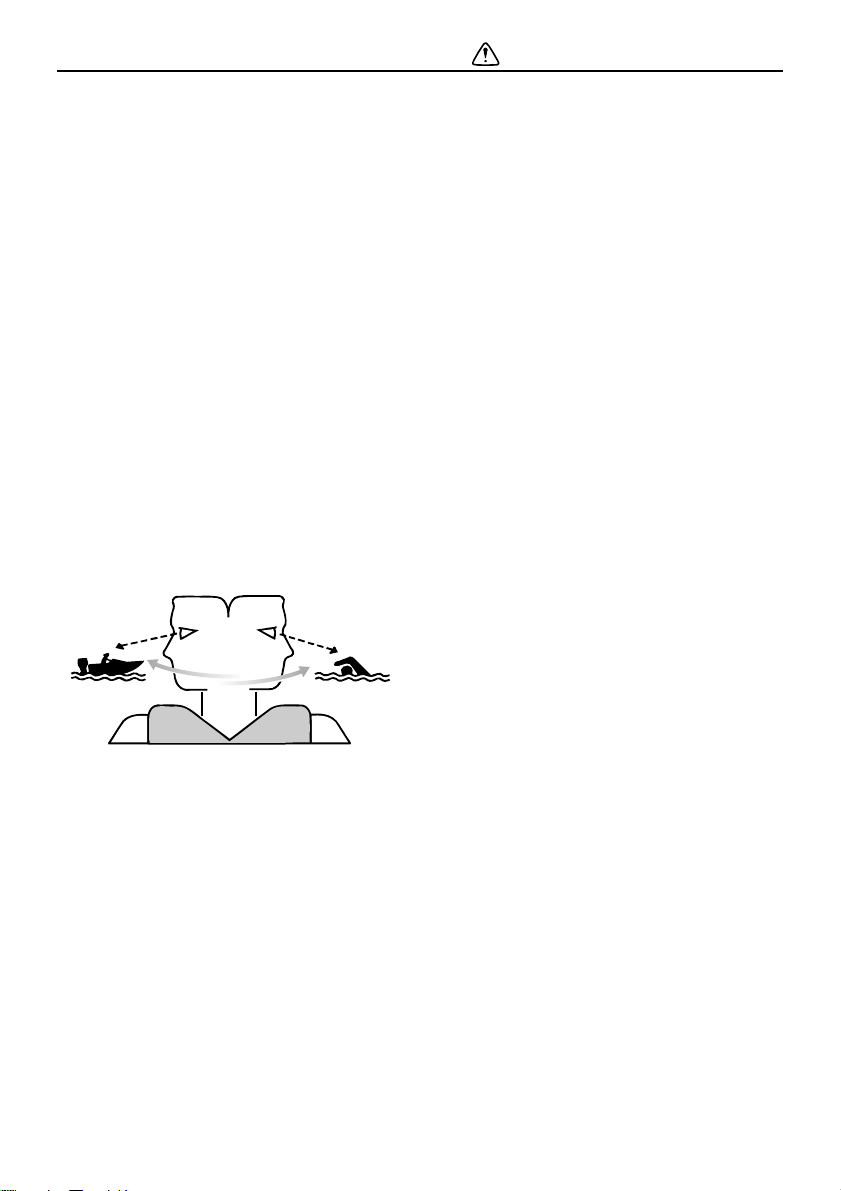
Always watch carefully for people in the water, such as swimmers, skiers, or divers,
whenever the engine is running. When
someone is in the water near the boat, shift
into neutral and stop the engine.
Stay away from swimming areas. Swimmers
can be hard to see.
The propeller can keep moving even when
the motor is in neutral. Stop the engine when
a person is in the water near you.
EMU33752
Passengers
Consult your boat manufacturer’s instructions for details about appropriate passenger
locations in your boat and be sure all passengers are positioned properly before accelerating and when operating above an idle
speed. Standing or sitting in non-designated
locations may result in being thrown either
overboard or within the boat due to waves,
wakes, or sudden changes in speed or direction. Even when people are positioned properly, alert your passengers if you must make
2
Page 9
Safety information
ZMU06025
any unusual maneuver. Always avoid jumping waves or wakes.
EMU33763
Overloading
Do not overload the boat. Consult the boat
capacity plate or boat manufacturer for maximum weight and number of passengers. Be
sure that weight is properly distributed according to the boat manufacturer’s instructions. Overloading or incorrect weight
distribution can compromise the boat’s handling and lead to an accident, capsizing or
swamping.
EMU33773
Avoid collisions
Scan constantly for people, objects, and other boats. Be alert for conditions that limit your
visibility or block your vision of others.
Operate defensively at safe speeds and
keep a safe distance away from people, objects, and other boats.
Do not follow directly behind other boats or
waterskiers.
Avoid sharp turns or other maneuvers that
make it hard for others to avoid you or understand where you are going.
Avoid areas with submerged objects or
shallow water.
Ride within your limits and avoid aggres-
sive maneuvers to reduce the risk of loss
of control, ejection, and collision.
Take early action to avoid collisions. Re-
member, boats do not have brakes, and
stopping the engine or reducing throttle
can reduce the ability to steer. If you are
not sure that you can stop in time before
hitting an obstacle, apply throttle and turn
in another direction.
EMU48100
Collisions with floating or
submerged objects
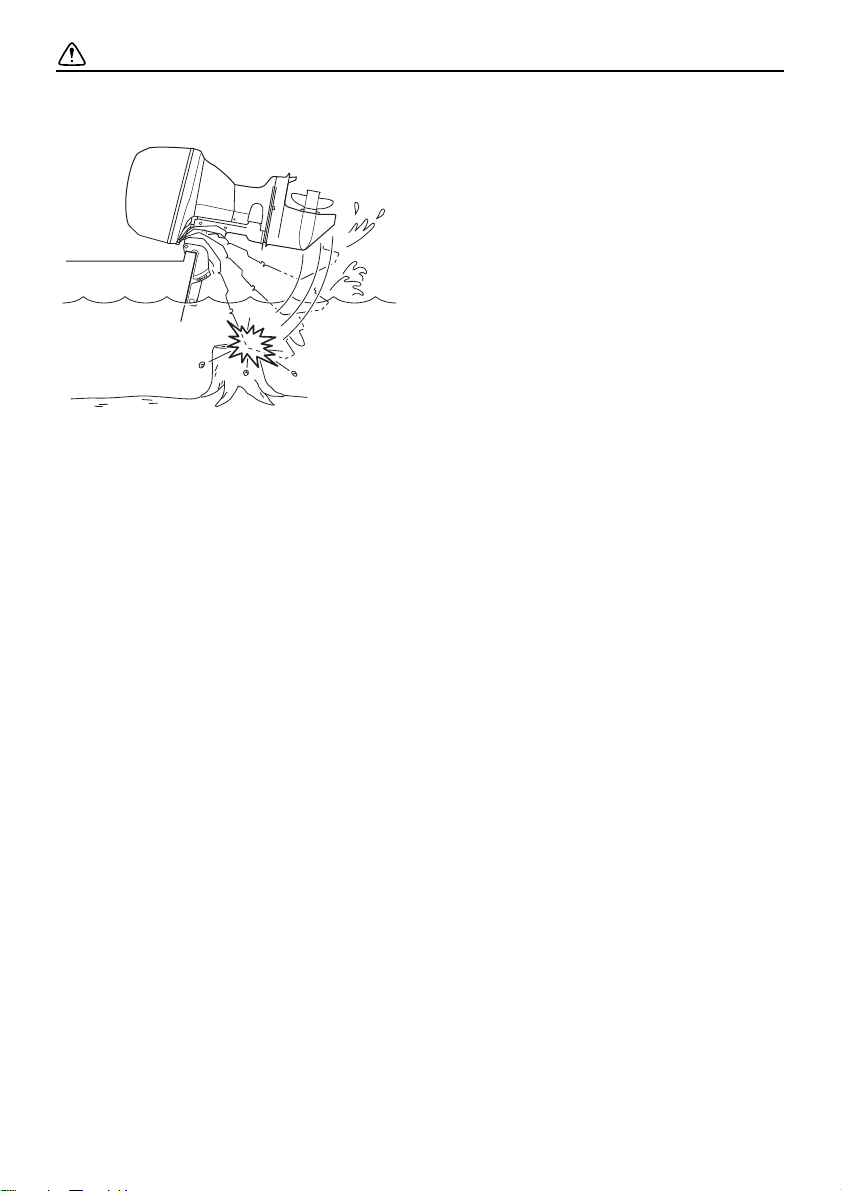
If the outboard motor hits a floating object or
an obstacle in the water while cruising, the
following could occur:
The passengers and any loose equipment
or luggage could be thrown forward due to
the sudden deceleration.
Parts of the outboard motor could come
loose as a result of the impact and could
be thrown into the boat.
The boat or outboard motor could be dam-
aged as a result of the impact.
When you operate the boat in an area where
there might be floating objects or obstacles
in the water, be sure to adjust the trim angle
of the outboard motor, slow down, and operate carefully. For further information, see
page 61.
If the outboard motor hits a floating object or
an obstacle in the water, make sure that
there are no abnormalities with the boat and
the outboard motor. If anything abnormal is
found, return to the nearest harbor at low
speed and have a Yamaha dealer inspect
the outboard motor.
3
Page 10
Safety information
EMU33791
Weather
Stay informed about the weather. Check
weather forecasts before boating. Avoid
boating in hazardous weather.
EMU33881
Passenger training
Make sure at least one other passenger is
trained to operate the boat in the event of an
emergency.
EMU33891
Boating safety publications
Be informed about boating safety. Additional
publications and information can be obtained
from many boating organizations.
EMU33602
Laws and regulations
Know the marine laws and regulations where
you will be boating—and obey them. Several
sets of rules prevail according to geographic
location, but all are basically the same as the
International Rules of the Road.
4
Page 11
General information
ZMU02931
1
3412
1
EMU25172
Identification numbers record
EMU25186
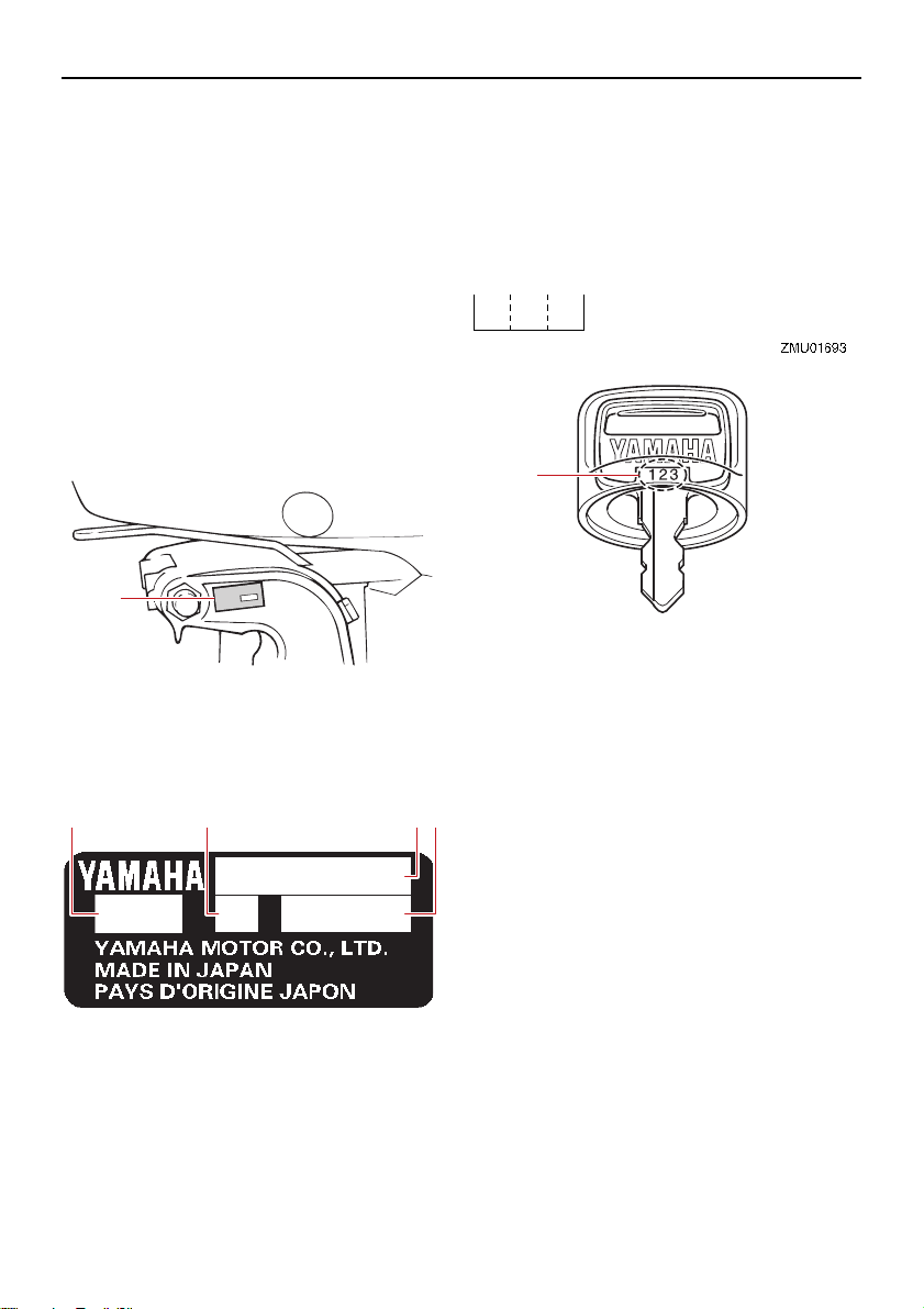
Outboard motor serial number
The outboard motor serial number is
stamped on the label attached to the port
side of the clamp bracket.
Record your outboard motor serial number in
the spaces provided to assist you in ordering
spare parts from your Yamaha dealer or for
reference in case your outboard motor is stolen.
1. Outboard motor serial number location
1. Serial number
2. Model name
3. Motor transom height
4. Approved model code
EMU25192
Key number
If a main key switch is equipped with the motor, the key identification number is stamped
on your key as shown in the illustration. Record this number in the space provided for
reference in case you need a new key.
1. Key number
EMU38983
EC Declaration of Conformity
(DoC)
This declaration is included with outboard
motors that conform to European regulations.
This outboard motor conforms to certain portions of the European Parliament directive
relating to machinery.
Each conformed outboard motor accompanied with EC DoC. EC DoC contains the following information;
Name of engine manufacturer
Model name
Product code of model (Approved model
code)
Code of conformed directives
5
Page 12
General information
1
ZMU06040
EMU38995
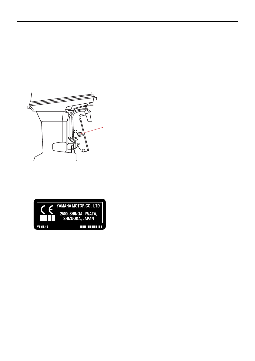
CE Marking
This label is affixed to outboard motors that
conform to European regulations.
Outboard motors affixed with this “CE” marking conform with the directives of;
2006/42/EC, 94/25/EC - 2003/44/EC,
2014/30/EU, and 2004/108/EC, 2013/53/EU.
1. CE marking location
6
Page 13
General information
ZMU07315
3
2
1
EMU33524
Read manuals and labels
Before operating or working on this outboard motor:
Read this manual.
Read any manuals supplied with the boat.
Read all labels on the outboard motor and the boat.
If you need any additional information, contact your Yamaha dealer.
EMU33836
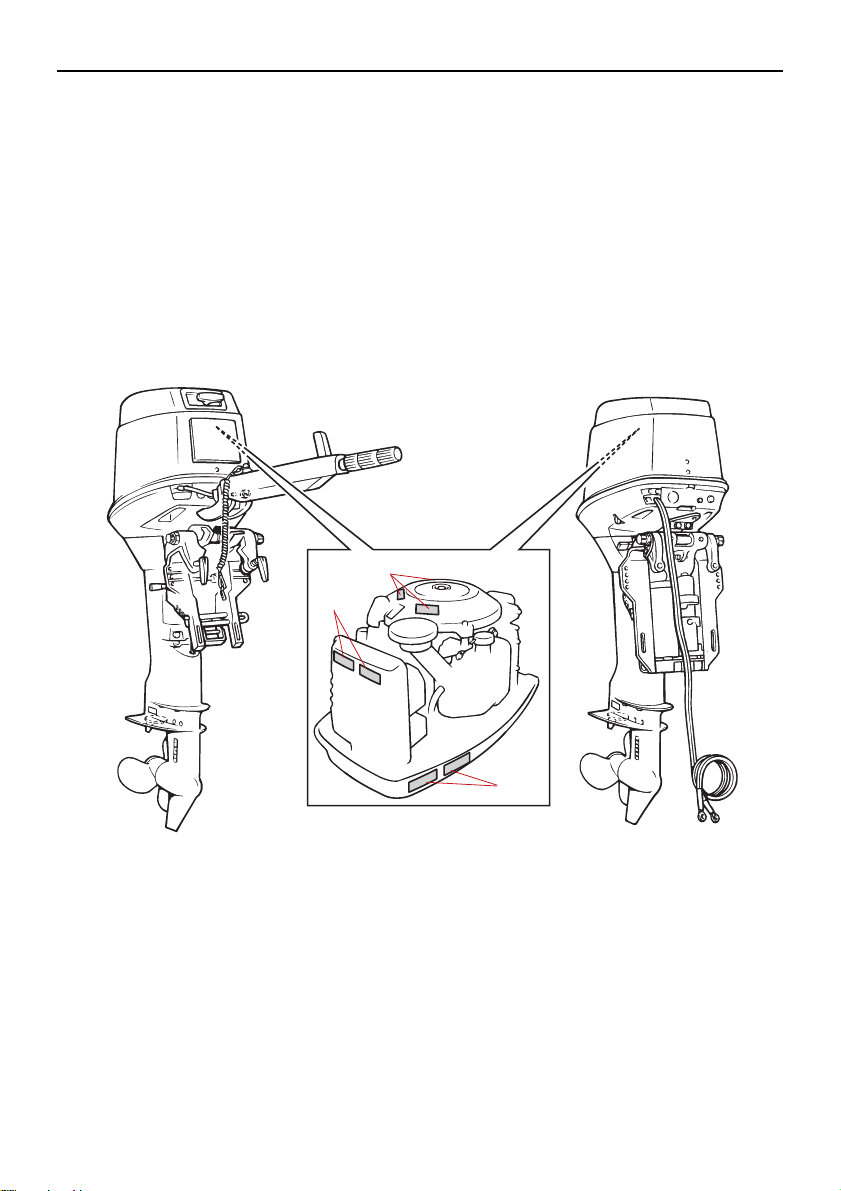
Warning labels
If these labels are damaged or missing, contact your Yamaha dealer for replacements.
7
Page 14
General information
6EE-G2794-40
6EE-G2794-50
6EE-H1994-40
6EE-H1994-50
6EE-H1995-40
6EE-H1995-50
ZMU05706
1
2
3
EMU33913
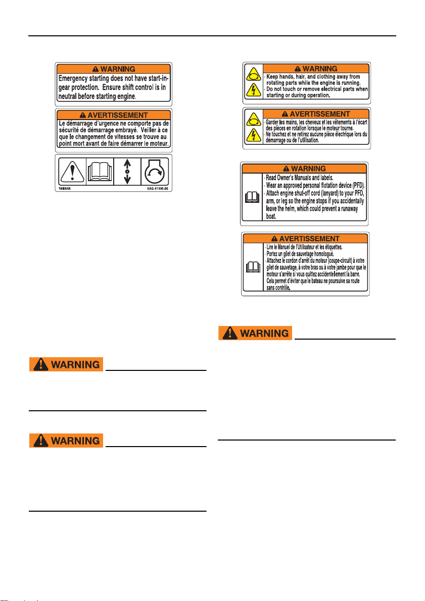
Contents of labels
The above warning labels mean as follows.
1
EWM01692
Emergency starting does not have startin-gear protection. Ensure shift control is
in neutral before starting engine.
2
EWM01682
Keep hands, hair, and clothing away
from rotating parts while the engine is
running.
Do not touch or remove electrical parts
when starting or during operation.
8
3
EWM01672
Read Owner’s Manuals and labels.
Wear an approved personal flotation
device (PFD).
Attach engine shut-off cord (lanyard) to
your PFD, arm, or leg so the engine
stops if you accidentally leave the
helm, which could prevent a runaway
boat.
Page 15
General information
ZMU05664
ZMU05666
ZMU05667
ZMU05668
EMU33844
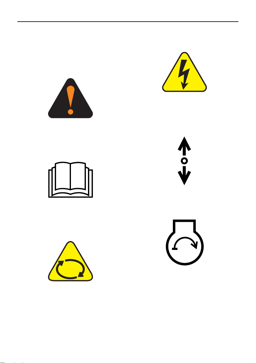
Symbols
The following symbols mean as follows.
Notice/Warning
ZMU05696
Read Owner’s Manual
Electrical hazard
Remote control lever/gear shift lever operating direction, dual direction
Engine start/ Engine cranking
Hazard caused by continuous rotation
ZMU05665
9
Page 16

Specifications and requirements
TIP:
EMU38092
Specifications
“(AL)” stated in the specification data below
represents the numerical value for the aluminum propeller installed.
EMU48360
Dimension and weight:
Overall length:
1281 mm (50.4 in) (40VMHO)
670 mm (26.4 in) (40VEO, 50HETO)
Overall width:
349 mm (13.7 in) (40VEO, 40VMHO)
360 mm (14.2 in) (50HETO)
Overall height S:
1223 mm (48.1 in) (40VMHO)
Overall height L:
1319 mm (51.9 in) (40VEO, 50HETO)
1350 mm (53.1 in) (40VMHO)
Motor transom height S:
406 mm (16.0 in) (40VMHO)
Motor transom height L:
533 mm (21.0 in)
Dry weight (AL) S:
76 kg (167 lb) (40VMHO)
Dry weight (AL) L:
77 kg (170 lb) (40VEO)
78 kg (171 lb) (40VMHO)
88 kg (194 lb) (50HETO)
Performance:
Full throttle operating range:
4500–5500 r/min
Rated power:
29.4 kW (40 HP) (40VEO, 40VMHO)
36.8 kW (50 HP) (50HETO)
Idle speed (in neutral):
750–850 r/min
Power unit:
Type:
2-stroke L3
Total displacement:
Bore stroke:
Ignition system:
Spark plug with resistor (NGK):
Spark plug gap:
Steering system:
Starting system:
Starting carburetion system:
Battery rating (CCA/EN):
Battery rating (20HR/IEC):
Alternator output:
Maximum generator output:
Lower unit:
Gear shift positions:
Gear ratio:
Trim and tilt system:
Propeller mark:
3
698 cm
67.0 66.0 mm (2.64 2.60 in)
CDI
BR7HS-10 (40VEO, 40VMHO)
BR8HS-10 (50HETO)
0.9–1.0 mm (0.035–0.039 in)
Remote steering (40VEO, 50HETO)
Tiller handle (40VMHO)
Electric starter (40VEO, 50HETO)
Manual starter (40VMHO)
Choke valve (40VMHO)
Prime start (40VEO, 50HETO)
347–411 A (40VEO, 50HETO)
40 Ah (40VEO, 50HETO)
80 W (40VMHO)
6 A (40VEO, 50HETO)
Forward-neutral-reverse
1.85 (24/13)
Manual tilt (40VEO, 40VMHO)
Power trim and tilt (50HETO)
G
(42.6 c.i.)
10
Page 17
Specifications and requirements
Fuel and oil:
Recommended fuel:
Regular unleaded gasoline
Min. research octane number (RON):
90
Fuel tank capacity:
24 L (6.34 US gal, 5.28 Imp.gal)
Recommended engine oil:
YAMALUBE 2-stroke outboard motor
oil
Recommended engine oil:
TC-W3
Lubrication system:
Oil injection
Engine oil tank capacity:
1.5 L (1.59 US qt, 1.32 Imp.qt)
Recommended gear oil:
YAMALUBE outboard gear oil or Hypoid gear oil
Recommended gear oil grade:
SAE 90 API GL-4
Gear oil quantity:
0.430 L (0.455 US qt, 0.378 Imp.qt)
Noise and vibration level:
Operator sound pressure level (ICOMIA
39/94):
89.5 dB(A) (40VEO, 40VMHO)
Vibration on tiller handle (ICOMIA 38/94):
Vibration on tiller handle is under 2.5
2
m/s
(40VMHO)
EMU33556
Installation requirements
EMU33566
Boat horsepower rating
EWM01561
Overpowering a boat can cause severe
instability.
Before installing the outboard motor(s), confirm that the total horsepower of your outboard motor(s) does not exceed the boat’s
maximum horsepower rating. See the boat’s
capacity plate or contact the manufacturer.
EMU40491
Mounting outboard motor
EWM02501
Improper mounting of the outboard mo-
tor could result in hazardous condi-
tions such as poor handling, loss of
control, or fire hazards.
Because the outboard motor is very
heavy, special equipment and training
is required to mount it safely.
Your dealer or other person experienced in
proper rigging should mount the outboard
motor using correct equipment and complete
rigging instructions. For further information,
see page 35.
EMU33582
Remote control requirements
EWM01581
If the engine starts in gear, the boat can
move suddenly and unexpectedly, pos-
sibly causing a collision or throwing
passengers overboard.
If the engine ever starts in gear, the
11
Page 18
Specifications and requirements
ZMU04606
-
x
123
start-in-gear protection device is not
working correctly and you should discontinue using the outboard. Contact
your Yamaha dealer.
The remote control unit must be equipped
with a start-in-gear protection device(s). This
device prevents the engine from starting unless it is in neutral.
EMU25695
Battery requirements
EMU25723
Battery specifications
Battery rating (CCA/EN):
347–411 A (40VEO, 50HETO)
Battery rating (20HR/IEC):
40 Ah (40VEO, 50HETO)
The engine cannot be started if battery voltage is too low.
EMU36293
Mounting battery
Mount the battery holder securely in a dry,
well-ventilated, vibration-free location in the
boat. WARNING! Do not put flammable
items, or loose heavy or metal objects in
the same compartment as the battery.
Fire, explosion or sparks could result.
[EWM01821]
Battery cable
The battery cable size and length are critical.
Consult your Yamaha dealer about the battery cable size and length.
make. The type, size, and design of your propeller have a direct impact on acceleration,
top speed, fuel economy, and even engine
life. Yamaha designs and manufactures propellers for every Yamaha outboard motor
and every application.
Your outboard motor came with a Yamaha
propeller selected to perform well over a
range of applications, but there may be uses
where a different propeller would be more
appropriate.
Your Yamaha dealer can help you select the
right propeller for your boating needs. Select
a propeller that will allow the engine to reach
the middle or upper half of the operating
range at full throttle with the maximum boatload. Generally, select a larger pitch propeller for a smaller operating load and a smaller
pitch propeller for a heavier load. If you carry
loads that vary widely, select the propeller
that lets the engine run in the proper range
for your maximum load but remember that
you may need to reduce your throttle setting
to stay within the recommended engine
speed range when carrying lighter loads.
To check the propeller, see page 73.
EMU34196
Propeller selection
Next to selecting an outboard motor, selecting the right propeller is one of the most important purchasing decisions a boater can
12
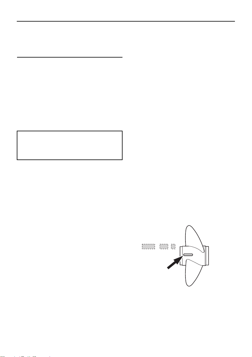
1. Propeller diameter in inches
2. Propeller pitch in inches
3. Type of propeller (propeller mark)
Page 19
Specifications and requirements
x
-
123
ZMU04607
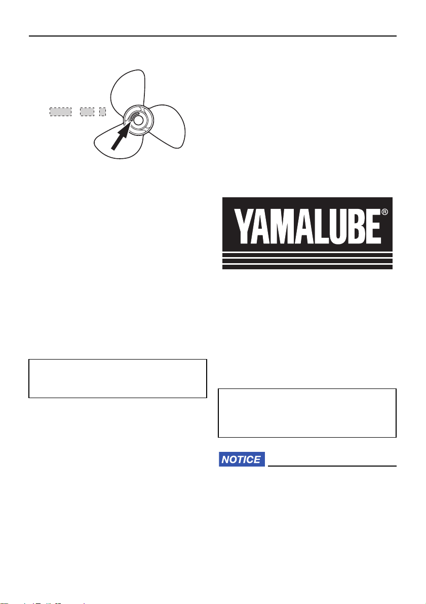
1. Propeller diameter in inches
2. Propeller pitch in inches
3. Type of propeller (propeller mark)
EMU25771
Start-in-gear protection
Yamaha outboard motors or Yamaha-approved remote control units are equipped
with start-in-gear protection device(s). This
feature permits the engine to be started only
when it is in neutral. Always select neutral
before starting the engine.
EMU25653
Engine oil requirements
Recommended engine oil:
YAMALUBE 2-stroke outboard motor
oil
If the recommended engine oil is not available, another 2-stroke engine oil with an
NMMA-certified TC-W3 rating may be used.
EMU48120
Why Yamalube
YAMALUBE oil is a Genuine YAMAHA Part
born of the engineers’ passion and belief that
engine oil is an important liquid engine component. We form teams of specialists in the
fields of mechanical engineering, chemistry,
electronics and track testing, and have them
develop the engine together with the oil it will
use. Yamalube oils take full advantage of the
base oil’s qualities and blend in the ideal balance of additives to make sure the final oil
clears our performance standards. Thus, Yamalube mineral, semisynthetic and synthetic
oils have their own distinct characters and
value. Yamaha’s experience gained over
many years of research and development
into oil since the 1960’s helps make Yamalube the best choice for your Yamaha engine.
EMU36361
Fuel requirements
EMU40203
Gasoline
Use a good quality gasoline that meets the
minimum octane rating. If knocking or pinging occurs, use a different brand of gasoline
or premium unleaded fuel.
Recommended fuel:
Regular unleaded gasoline
Min. research octane number (RON):
90
ECM01982
Do not use leaded gasoline. Leaded
gasoline can seriously damage the en-
gine.
Avoid getting water and contaminants
in the fuel tank. Contaminated fuel can
cause poor performance or engine
13
Page 20
Specifications and requirements
TIP:
E5 E10
damage. Use only fresh gasoline that
has been stored in clean containers.
This mark identifies the recommended fuel
for this outboard motor as specified by European regulation (EN228).
Check that gasoline nozzle has the same
identifier when fueling.
Gasohol
There are two types of gasohol: gasohol containing ethanol (E5 and E10) and that containing methanol. Ethanol can be used if the
ethanol content does not exceed 10% and
the fuel meets the minimum octane ratings.
E85 is a fuel containing 85% ethanol and
must not be used in your outboard motor. All
ethanol blends containing more than 10%
ethanol can cause fuel system damage or
cause engine starting and running problems.
Yamaha does not recommend gasohol containing methanol because it can cause fuel
system damage or engine performance
problems.
It is recommended that you install a waterseparating marine fuel filter assembly (10 micron minimum) between your boat’s fuel tank
and outboard motor when using ethanol.
Ethanol is known to allow moisture to be absorbed into boat fuel tanks and systems.
Moisture in the fuel can cause corrosion of
metallic fuel system components, starting
and running complaints and require additional fuel system maintenance.
EMU36881
Muddy or acidic water
Yamaha strongly recommends that you have
your dealer install the optional chromiumplated water pump kit if you use the outboard
motor in muddy or acidic water conditions.
However, depending on the model it might
not be required.
EMU36331
Anti-fouling paint
A clean hull improves boat performance. The
boat bottom should be kept as clean of marine growth as possible. If necessary, the
boat bottom can be coated with an anti-fouling paint approved for your area to inhibit
marine growth.
Do not use anti-fouling paint which includes
copper or graphite. These paints can cause
more rapid engine corrosion.
EMU40302
Outboard motor disposal
requirements
Never illegally discard (dump) the outboard
motor. Yamaha recommends consulting the
dealer about discarding the outboard motor.
14
Page 21

Specifications and requirements
EMU36353
Emergency equipment
Keep the following items onboard in case
there is trouble with the outboard motor.
A tool kit with assorted screwdrivers, pli-
ers, wrenches (including metric sizes), and
electrical tape.
Waterproof flashlight with extra batteries.
An extra engine shut-off cord (lanyard)
with clip.
Spare parts, such as an extra set of spark
plugs.
Consult your Yamaha dealer for details.
15
Page 22
Components
TIP:
ZMU03344
1
2
3
4
5
6
7
16
8
9
10
11
12
13
14
15
EMU46722
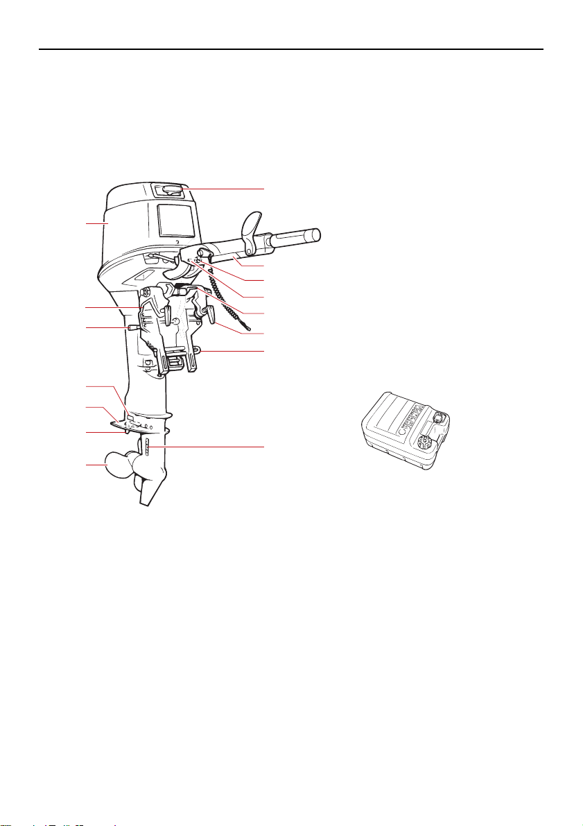
Components diagram
* May not be exactly as shown; also may not be included as standard equipment on all models (order from dealer).
40VMHO
1. Manual starter handle
2. Tiller handle*
3. Choke knob
4. Alert indicator
5. Tilt lock lever
6. Clamp screw
7. Trim rod
8. Cooling water inlet
9. Propeller
10. Trim tab (anode)
11. Anti-cavitation plate
12. Anode
13. Tilt support lever
14. Clamp bracket
15. Top cowling
16
16. Fuel tank*
Page 23
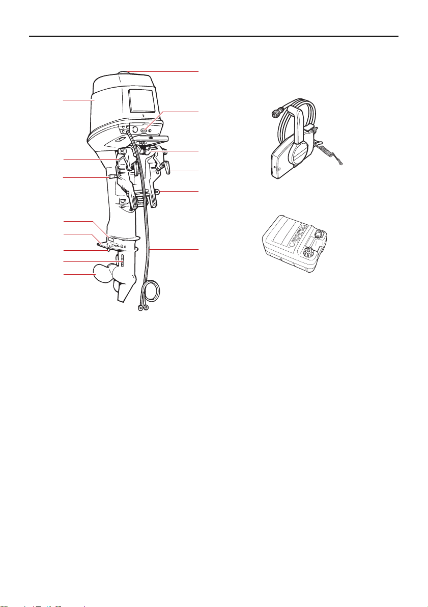
40VEO
7
8
9
10
11
12
13
14
1
15
16
2
3
4
5
6
1. Oil tank filler cap
2. Alert indicator(s)
3. Tilt lock lever
4. Clamp screw
5. Trim rod
6. Battery cable
7. Propeller
8. Cooling water inlet
9. Trim tab (anode)
10. Anti-cavitation plate
11. Anode
12. Tilt support lever
13. Clamp bracket
14. Top cowling
15. Remote control box (side mount type)
16. Fuel tank*
Components
17
Page 24
Components
1
12
13 14 15
16
2
3
5
4
6
7
3
8
9
10
11
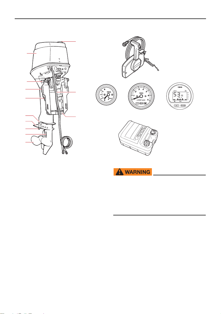
50HETO
1. Oil tank filler cap
2. Battery cable
3. Anode(s)
4. Propeller
5. Cooling water inlet
6. Trim tab (anode)
7. Anti-cavitation plate
8. Trim rod
9. Clamp bracket
10. Tilt support lever
11. Top cowling
12. Remote control box (side mount type)
13. Trim meter*
14. Tachometer*
15. Digital tachometer
16. Fuel tank*
EMU25804
Fuel tank
If your model was equipped with a portable
fuel tank, its function is as follows.
18
EWM00021
The fuel tank supplied with this engine is
its dedicated fuel reservoir and must not
be used as a fuel storage container. Commercial users should conform to relevant
licensing or approval authority regulations.
Page 25
Components
ZMU02284
3
1
4
2
1
2
3
5
4
6
7
ZMU01723
1
23
44
5
5
6
6
7
7
F
N
R
ZMU01725
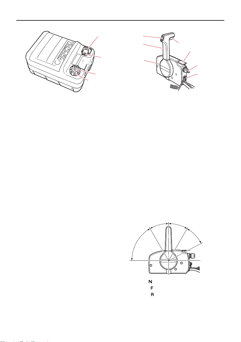
1. Fuel joint
2. Fuel gauge
3. Fuel tank cap
4. Air vent screw
EMU25831
Fuel joint
This joint is used to connect the fuel line.
EMU25842
Fuel gauge
This gauge is located on either the fuel tank
cap or on the fuel joint base. It shows the approximate amount of fuel remaining in the
tank.
EMU25851
Fuel tank cap
This cap seals the fuel tank. When removed,
the tank can be filled with fuel. To remove the
cap, turn it counterclockwise.
EMU25861
Air vent screw
This screw is on the fuel tank cap. To loosen
the screw, turn it counterclockwise.
1. Power trim and tilt switch
2. Remote control lever
3. Neutral interlock trigger
4. Neutral throttle lever
5. Main switch
6. Engine shut-off switch
7. Throttle friction adjuster
EMU26191
Remote control lever
Moving the lever forward from the neutral position engages forward gear. Pulling the lever back from neutral engages reverse. The
engine will continue to run at idle until the lever is moved about 35 (a detent can be felt).
Moving the lever farther opens the throttle,
and the engine will begin to accelerate.
EMU26182
Remote control box
The remote control lever actuates both the
shifter and the throttle. The electrical switches are mounted on the remote control box.
1. Neutral “ ”
2. Forward “ ”
3. Reverse “ ”
4. Shift
5. Fully closed
19
Page 26
Components
TIP:
1
2
N
ZMU01728
22
1
3
2
1
3
6. Throttle
7. Fully open
EMU26202
Neutral interlock trigger
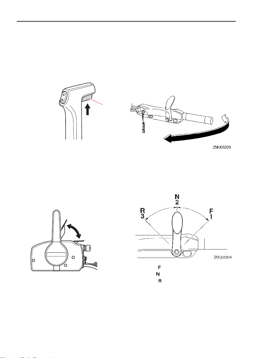
To shift out of neutral, first pull the neutral interlock trigger up.
1
ZMU01727
1. Neutral interlock trigger
EMU26213
Neutral throttle lever
To open the throttle without shifting into either forward or reverse, put the remote control lever in the neutral position and lift the
neutral throttle lever.
when the neutral throttle lever is in the closed
position.
EMU25914
Tiller handle
To change direction, move the tiller handle to
the left or right as necessary.
EMU25925
Gear shift lever
Move the gear shift lever forward to engage
the forward gear or rearward to engage the
reverse gear.
1. Fully open
2. Fully closed
The neutral throttle lever will operate only
when the remote control lever is in neutral.
The remote control lever will operate only
20
1. Forward “ ”
2. Neutral “ ”
3. Reverse “ ”
EMU25943
Throttle grip
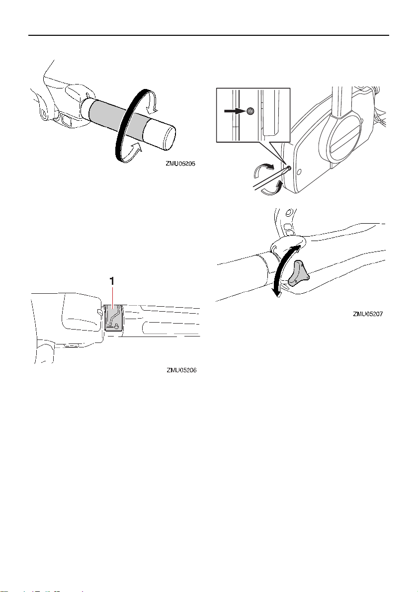
The throttle grip is on the tiller handle. Turn
the grip counterclockwise to increase speed
and clockwise to decrease speed.
Page 27
EMU25963
111
ZMU03095
Throttle indicator
The fuel consumption curve on the throttle
indicator shows the relative amount of fuel
consumed for each throttle position. Choose
the setting that offers the best performance
and fuel economy for the desired operation.
Components
difficult to move the remote control lever
or throttle grip, which could result in an
accident.
[EWM00033]
1. Throttle indicator
EMU25978
Throttle friction adjuster
A friction device provides adjustable resistance to movement of the throttle grip or the
remote control lever, and can be set according to operator preference.
To increase resistance, turn the adjuster
clockwise. To decrease resistance, turn the
adjuster counterclockwise. WARNING! Do
not overtighten the friction adjuster. If
there is too much resistance, it could be
When constant speed is desired, tighten the
adjuster to maintain the desired throttle setting.
EMU25996
Engine shut-off cord (lanyard) and
clip
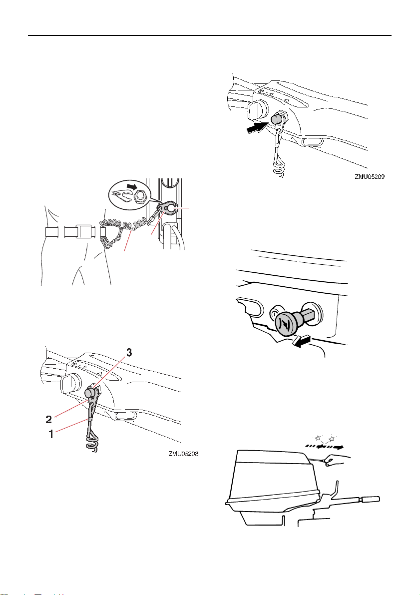
The clip must be attached to the engine shutoff switch for the engine to run. The cord
should be attached to a secure place on the
operator’s clothing, or arm or leg. Should the
operator fall overboard or leave the helm, the
cord will pull out the clip, stopping ignition to
the engine. This will prevent the boat from
running away under power. WARNING! At-
tach the engine shut-off cord to a secure
place on your clothing, or your arm or leg
while operating. Do not attach the cord to
21
Page 28
Components
ZMU01716
1
2
3
1
11
222
333
ZMU03355
ZMU02942
clothing that could tear loose. Do not
route the cord where it could become entangled, preventing it from functioning.
Avoid accidentally pulling the cord during normal operation. Loss of engine
power means the loss of most steering
control. Also, without engine power, the
boat could slow rapidly. This could cause
people and objects in the boat to be
thrown forward.
1. Engine shut-off cord (lanyard)
2. Clip
3. Engine shut-off switch
[EWM00123]
when the button is pushed.
EMU26015
Pull-type choke knob
Pull the choke knob to supply a rich fuel mixture to the engine.
1. Engine shut-off cord (lanyard)
2. Clip
3. Engine shut-off switch
EMU26004
Engine stop button
The engine stop button stops the engine
22
EMU26075
Manual starter handle
The manual starter handle is used to crank
and start the engine.
Page 29
Components
TIP:
EMU26092
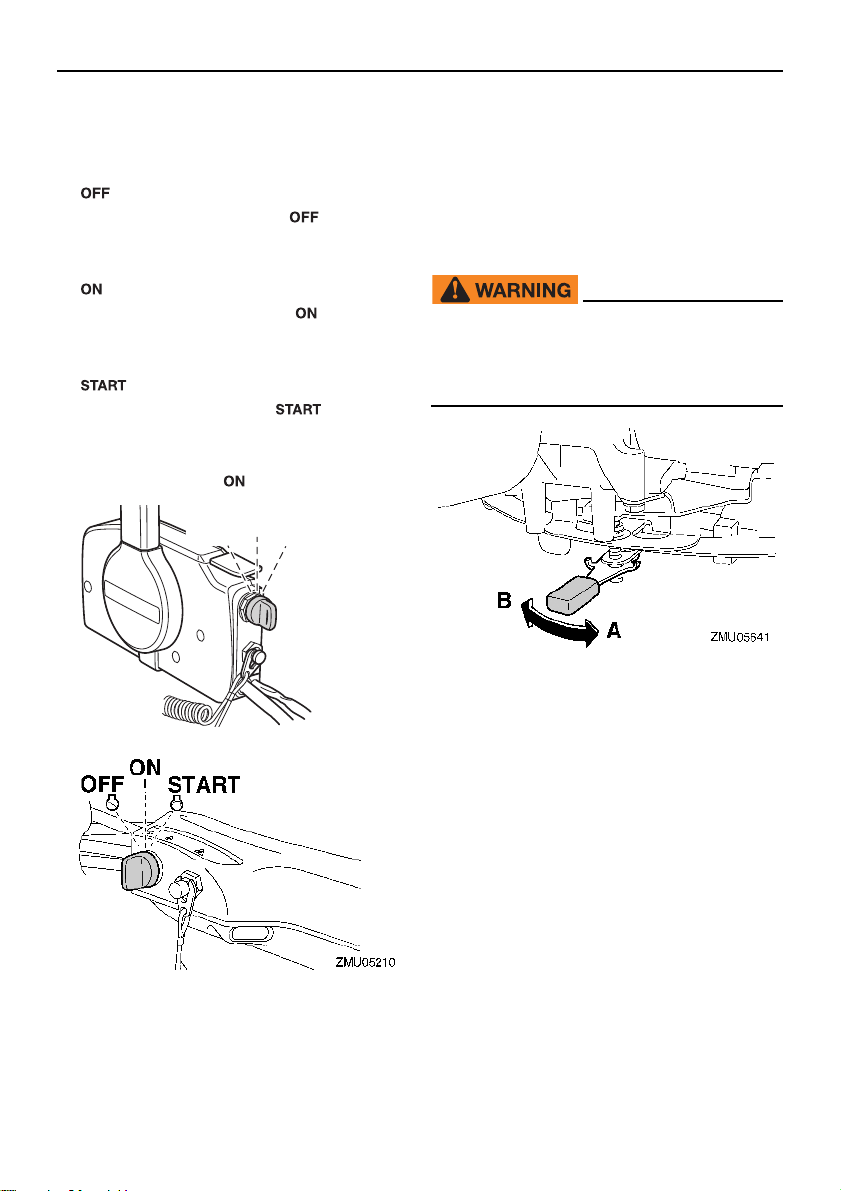
Main switch
The main switch controls the ignition system;
its operation is described below.
“” (off)
With the main switch in the “ ” (off) position, the electrical circuits are off, and the key
can be removed.
“” (on)
With the main switch in the “ ” (on) position, the electrical circuits are on, and the key
cannot be removed.
“” (start)
With the main switch in the “ ” (start) position, the starter motor turns to start the engine. When the key is released, it returns
automatically to the “ ” (on) position.
ON
STARTOFF
set according to operator preference. An adjuster lever is located on the bottom of the tiller handle bracket.
To increase resistance, turn the lever to the
port side “A”.
To decrease resistance, turn the lever to the
starboard side “B”.
EWM00041
Do not overtighten the friction adjuster. If
there is too much resistance, it could be
difficult to steer, which could result in an
accident.
EMU26113
Steering friction adjuster
A friction device provides adjustable resistance to the steering mechanism, and can be
ZMU01718
Check the tiller handle for smooth move-
ment when the lever is turned to the star-
board side “B”.
Do not apply lubricants such as grease to
the friction areas of the steering friction ad-
juster.
EMU26124
Steering friction adjuster
A friction device provides adjustable resistance to the steering mechanism, and can be
set according to operator preference. An adjusting screw or bolt is located on the swivel
bracket.
23
Page 30
Components
ZMU02908
DN
UP
ZMU01720
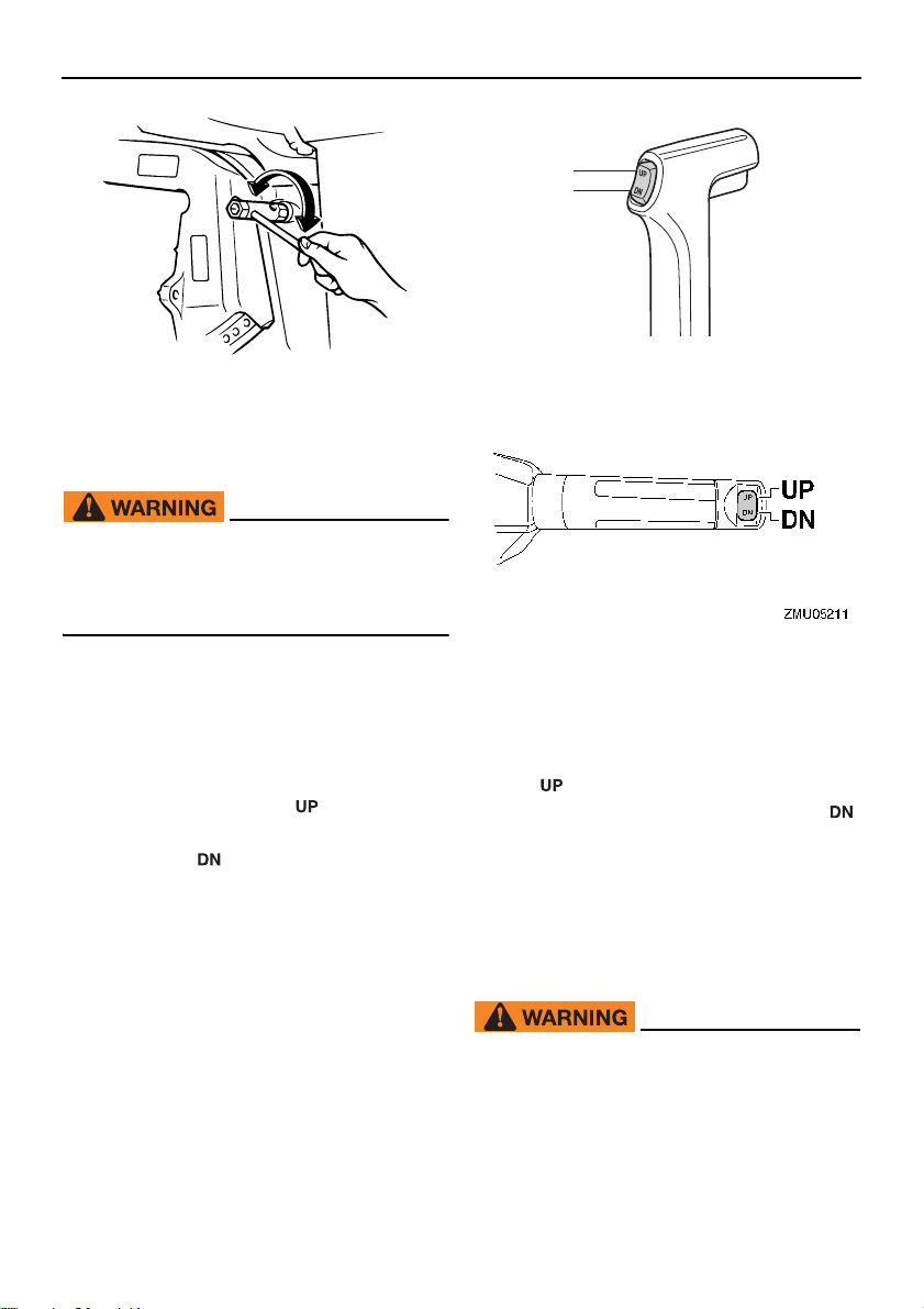
To increase resistance, turn the adjuster
clockwise.
To decrease resistance, turn the adjuster
counterclockwise.
EWM00041
Do not overtighten the friction adjuster. If
there is too much resistance, it could be
difficult to steer, which could result in an
accident.
EMU26144
Power trim and tilt switch on remote
control or tiller handle
The power trim and tilt system adjusts the
outboard motor angle in relation to the transom. Pressing the switch “ ” (up) trims the
outboard motor up, and then tilts it up. Pressing the switch “ ” (down) tilts the outboard
motor down and trims it down. When the
switch is released, the outboard motor will
stop in its current position.
For instructions on using the power trim and
tilt switch, see pages 55 and 58.
EMU26156
Power trim and tilt switch on bottom
cowling
The power trim and tilt switch is located on
the side of the bottom cowling. Pushing the
switch “ ” (up) trims the outboard motor up,
and then tilts it up. Pushing the switch “ ”
(down) tilts the outboard motor down and
trims it down. When the switch is released,
the outboard motor will stop in its current position.
For instructions on using the power trim and
tilt switch, see page 58.
EWM01032
24
Use the power trim and tilt switch located
on the bottom cowling only when the boat
is at a complete stop with the engine off.
Attempting to use this switch while the
boat is moving could increase the risk of
falling overboard and could distract the
Page 31
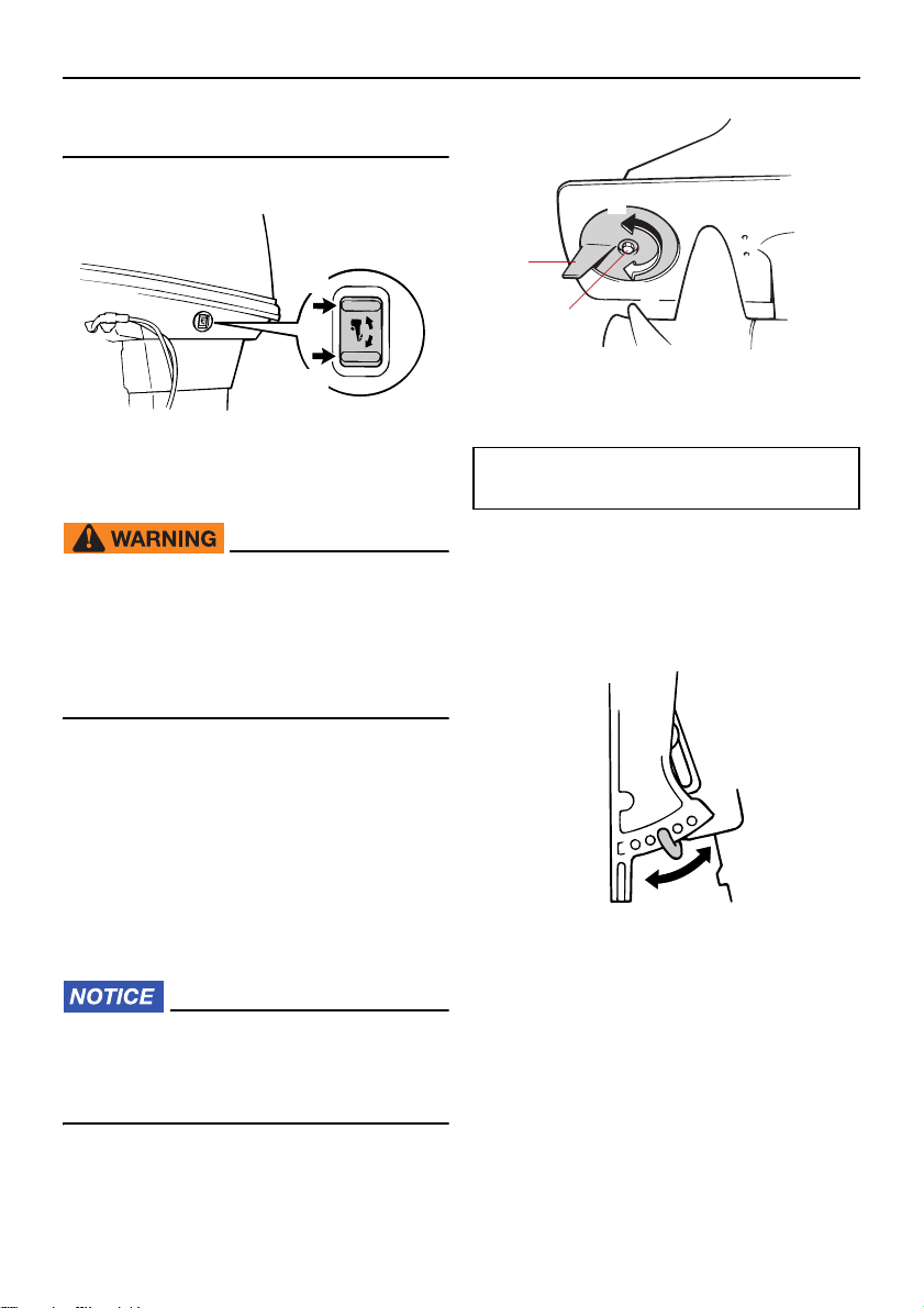
operator, increasing the risk of collision
UP
DN
ZMU03096
A
B
ZMU03097
1
2
ZMU03098
with another boat or an obstacle.
Components
1. Trim tab
2. Bolt
EMU26246
Trim tab with anode
EWM00841
An improperly adjusted trim tab could
cause difficult steering. Always test run
after the trim tab has been installed or replaced to be sure steering is correct. Be
sure you have tightened the bolt after adjusting the trim tab.
The trim tab should be adjusted so that the
steering control can be turned to either the
right or left by applying the same amount of
force.
If the boat tends to veer to the left (port side),
turn the trim tab rear end to the port side “A”
in the figure. If the boat tends to veer to the
right (starboard side), turn the trim tab end to
the starboard side “B” in the figure.
ECM00841
The trim tab also serves as an anode to
protect the engine from electrochemical
corrosion. Never paint the trim tab as it
will become ineffective as an anode.
Bolt tightening torque:
18 N·m (1.8 kgf·m, 13 lb·ft)
EMU26263
Trim rod (tilt pin)
The position of the trim rod determines the
minimum trim angle of the outboard motor in
relation to the transom.
EMU30531
Tilt lock mechanism
The tilt lock mechanism is used to prevent
the outboard motor from lifting out of the water when in reverse gear.
25
Page 32
Components
1
ZMU06790
ZMU03194
ZMU03358
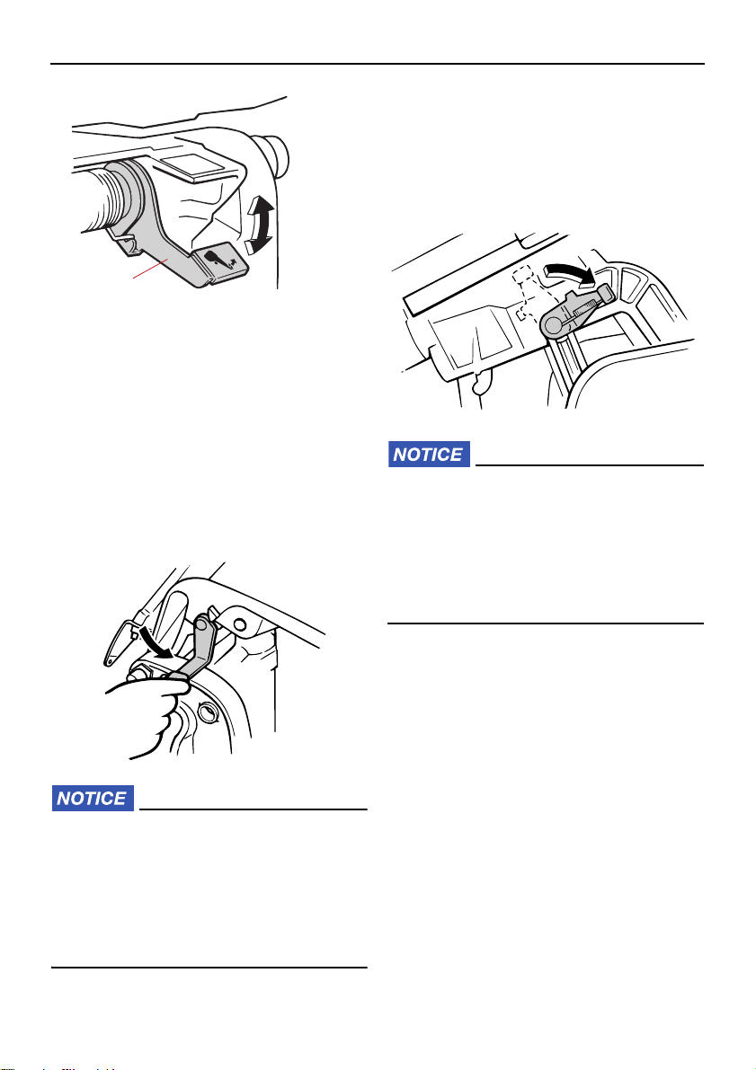
1. Tilt lock lever
To lock it, set the tilt lock lever in the lock position. To release, push the tilt lock lever in
the release position.
EMU30202
Tilt support lever for manual tilt
model
To keep the outboard motor in the tilted up
position, lock the tilt support lever to the
clamp bracket.
EMU26342
Tilt support lever for power trim and
tilt model
To keep the outboard motor in the tilted up
position, lock the tilt support lever to the
clamp bracket.
ECM00661
Do not use the tilt support lever or knob
when trailering the boat. The outboard
motor could shake loose from the tilt support and fall. If the motor cannot be
trailered in the normal running position,
use an additional support device to secure it in the tilt position.
ECM00661
Do not use the tilt support lever or knob
when trailering the boat. The outboard
motor could shake loose from the tilt support and fall. If the motor cannot be
trailered in the normal running position,
use an additional support device to secure it in the tilt position.
EMU26374
Cowling lock lever(s) (turn type)
To remove the engine top cowling, turn the
cowling lock lever(s) and lift off the cowling.
When installing the cowling, check to be sure
it fits properly in the rubber seal. Then lock
the cowling again by returning the cowling
lock lever(s) to the lock position.
26
Page 33
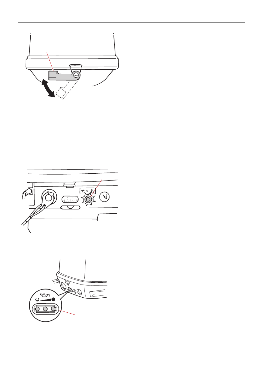
1. Cowling lock lever(s)
ZMU02862
1
ZMU03361
1
1
ZMU03360
EMU26305
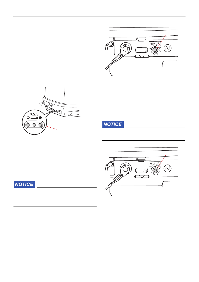
Alert indicator
If the engine develops a condition which is
cause for alert, the indicator lights up. For
details on how to read the alert indicator, see
page 32.
Components
1. Alert indicator
1. Alert indicator(s)
27
Page 34
Instruments and indicators
1
ZMU03360
ZMU03361
1
EMU36016
Indicators
EMU26292
Alert indicator for three indicators
If the engine develops a condition which is
cause for alert, the indicator on the front of
the bottom cowling lights up. The three indicators mounted on the bottom cowling also
indicate the engine oil level. For details on
how to read the alert indicators, see page 32.
1. Alert indicator(s)
1. Overheat-alert indicator
EMU37561
Oil level-alert indicator
If the oil level falls below the lower limit, this
indicator will light up. For further information,
see page 32.
ECM00031
Do not operate the engine without oil. Serious engine damage will occur.
EMU36034
Overheat-alert indicator
If the engine temperature rises too high, this
indicator will light up. For further information
on reading the indicator, see page 32.
ECM00053
Do not continue to run the engine if the
overheat-alert indicator is on. Serious engine damage will occur.
28
1
ZMU03361
1. Oil level-alert indicator
EMU26494
Digital tachometer
The tachometer shows the engine speed
and has the following functions.
All segments of the display will light momentarily after the main switch is turned on and
will return to normal thereafter.
Page 35
Instruments and indicators
TIP:
1
3
5
6
7
4
2
ZMU01891
ZMU01869
ZMU01870
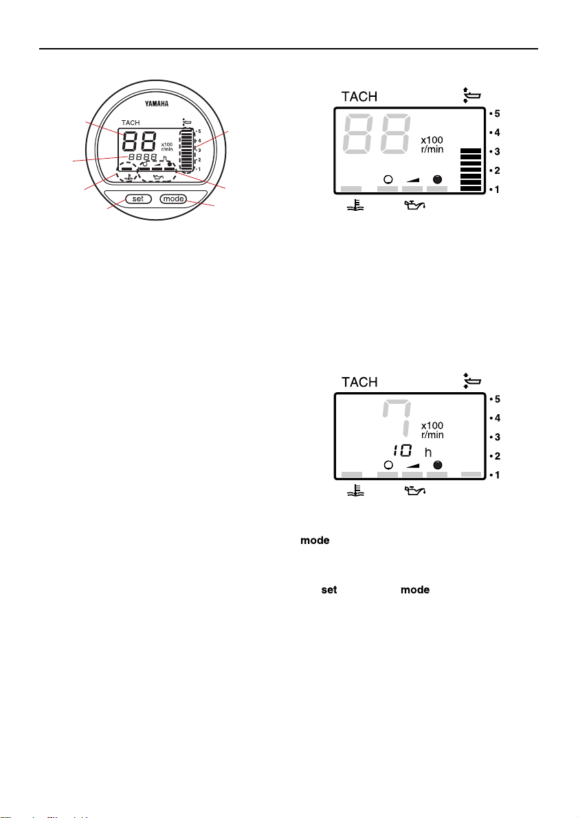
1. Tachometer
2. Trim meter
3. Hour meter
4. Oil level indicator
5. Overheat-alert indicator
6. Set button
7. Mode button
The water separator and engine trouble-alert
indicators only operate when the engine is
equipped with the appropriate functions.
EMU36051
Tachometer
The tachometer displays engine speed in
hundreds of revolutions per minute (r/min).
For example, if the tachometer display reads
“22” then the engine speed is 2200 r/min.
EMU26622
Trim meter
This meter shows the trim angle of your outboard motor.
Memorize the trim angles that work best
for your boat under different conditions.
Adjust the trim angle to the desired using
the power trim and tilt switch.
If the trim angle of your motor exceeds the
trim operating range, the top segment on
the trim meter display will blink.
EMU26652
Hour meter
This meter shows the number of hours the
engine has been run. It can be set to show
the total number of hours or the number of
hours for the current trip. The display can
also be turned on and off.
To change the display format, press the
“ ” (mode) button. The display can show
total hours or trip hours, or turn off.
To reset the trip hours, simultaneously press
the “ ” (set) and “ ” (mode) buttons for
more than 1 second while the trip hours are
displayed. This resets the trip counter to 0
(zero).
The total number of hours the engine has
been run cannot be reset.
EMU26552
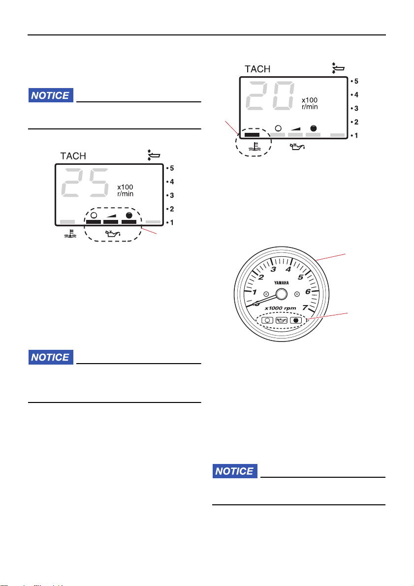
Oil level indicator (digital type)
This indicator shows the engine oil level. If
29
Page 36
Instruments and indicators
1
ZMU01867
1
ZMU01868
ZMU04577
1
2
the oil level falls below the lower limit, the
alert indicator will start to blink. For further information, see page 33.
ECM00031
Do not operate the engine without oil. Serious engine damage will occur.
1. Overheat-alert indicator
EMU26472
This gauge shows the engine speed and has
the following functions.
1. Oil level indicator
EMU26584
Overheat-alert indicator
If the engine temperature rises too high, the
alert indicator will start to blink. For further information on reading the indicator, see page
32.
ECM00053
1. Tachometer
Do not continue to run the engine if the
overheat-alert indicator is on. Serious engine damage will occur.
2. Oil level indicator
EMU26542
Oil level indicators (three indicators
2)
The indicators on the gauge show the status
of the oil level. For details on how to read the
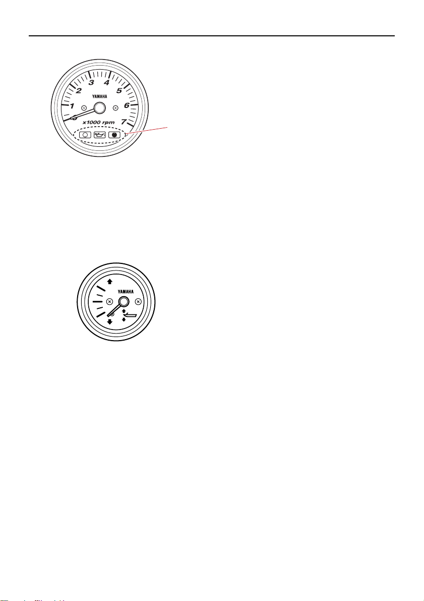
indicators, see page 45.
ECM00031
Analog tachometer
Do not operate the engine without oil. Serious engine damage will occur.
30
Page 37
Instruments and indicators
ZMU04580
1
ZMU04581
1. Oil level indicators
EMU26612
Analog trim meter
This gauge shows the trim angle of your outboard motor.
Memorize the trim angles that work best for
your boat under different conditions. Adjust
the trim angle to the desired setting with the
power trim and tilt switch.
31
Page 38
Engine control system
ZMU04766
ZMU03364
ZMU01757
ZMU03026
EMU26806
Alert system
ECM00093
Do not continue to operate the engine if
an alert device has activated. Consult
your Yamaha dealer if the problem cannot
be located and corrected.
EMU43754
Overheat alert
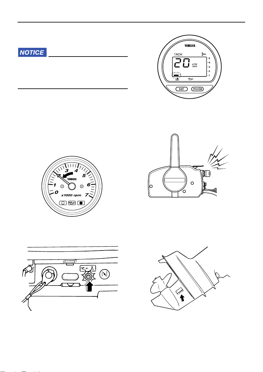
This engine has an overheat-alert device. If
the engine temperature rises too high, the
alert device will activate.
The engine speed will automatically de-
crease to 2000–3500 r/min.
The buzzer will sound (if equipped on the
tiller handle, remote control box, or main
switch panel).
ZMU03025
The overheat-alert indicator will light or
blink (if equipped).
32
If the alert system has activated, stop the engine and check the cooling water inlets:
Check trim angle to be sure that the cool-
ing water inlet is submerged.
Check the cooling water inlet for clogging.
Page 39
EMU2684B
TIP:
ZMU04586
ZMU03364
ZMU03363
ZMU03942
ZMU01758
Oil level alert and oil filter clogging
alert
Oil injection models
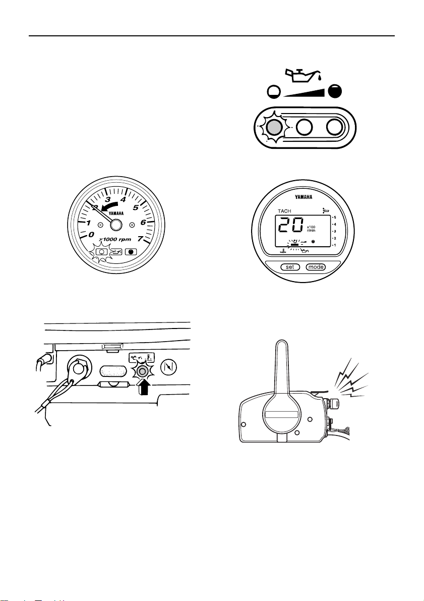
This engine has an oil level alert system. If
the oil level falls below the lower limit, the
alert system will activate.
Activation of alert device
Engine speed will automatically decrease
to about 2000–3500 r/min.
Engine control system
The oil level-alert indicator will light or
blink.
The buzzer will sound (if equipped on the
tiller handle, remote control box, or main
switch panel).
If the alert system has been activated, stop
the engine and check for the cause.
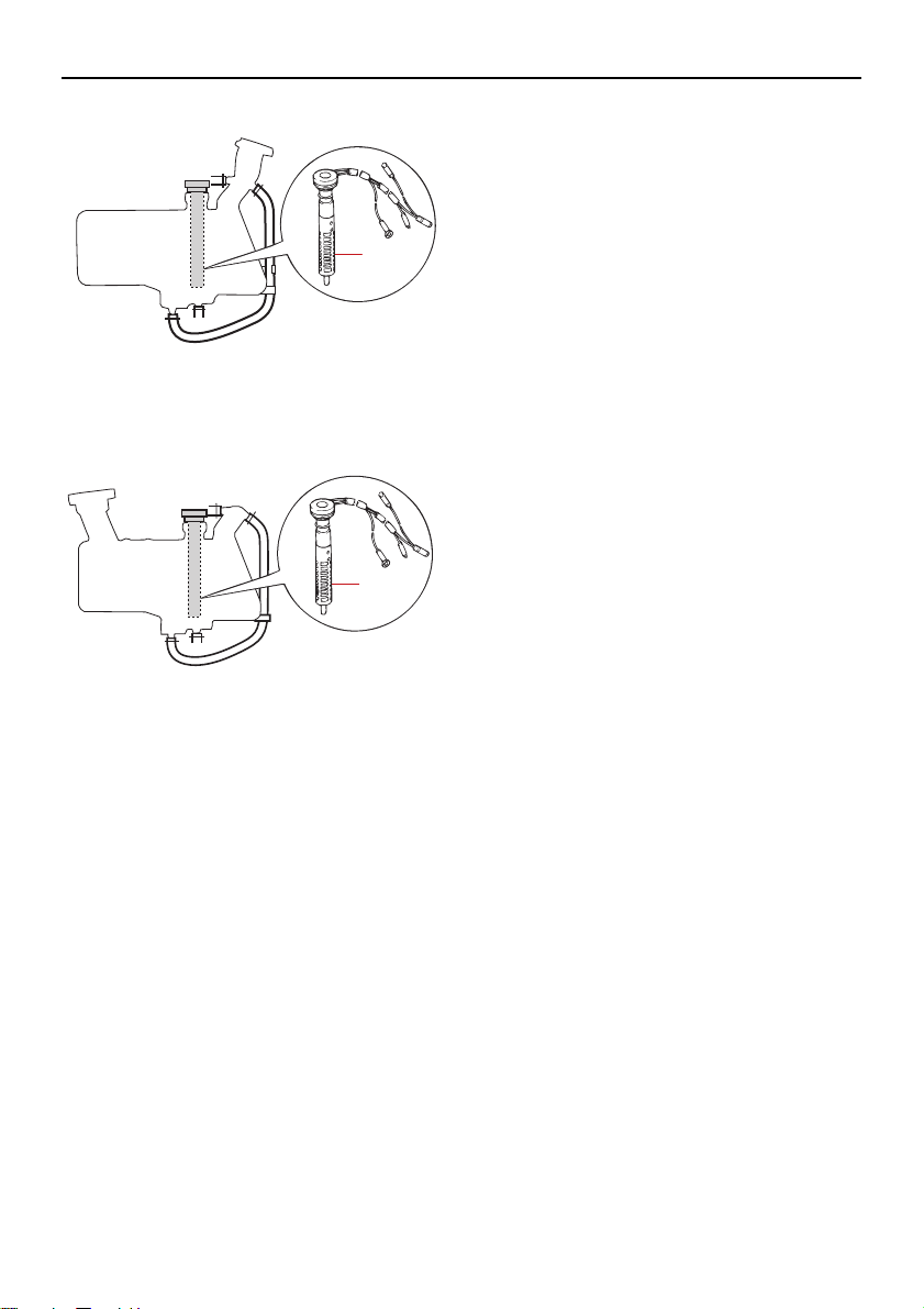
The alert for oil filter clogging is similar to the
alerts for low oil level and overheating. To
make troubleshooting easier, check for engine overheating first, then oil level, and finally oil filter clogging.
33
Page 40
Engine control system
1
ZMU06661
1
ZMU06662
1. Oil filter
1. Oil filter
34
Page 41
EMU26903
ZMU01760
1
Installation
The information presented in this section is
intended as reference only. It is not possible
to provide complete instructions for every
possible boat and motor combination. Proper
mounting depends in part on experience and
the specific boat and motor combination.
EWM01591
Installation
Overpowering a boat could cause se-
vere instability. Do not install an outboard motor with more horsepower
than the maximum rating on the capacity plate of the boat. If the boat does not
have a capacity plate, consult the boat
manufacturer.
Improper mounting of the outboard mo-
tor could result in hazardous conditions such as poor handling, loss of
control, or fire hazards. For permanently mounted models, your dealer or other person experienced in proper rigging
should mount the motor.
EMU33471
Mounting the outboard motor
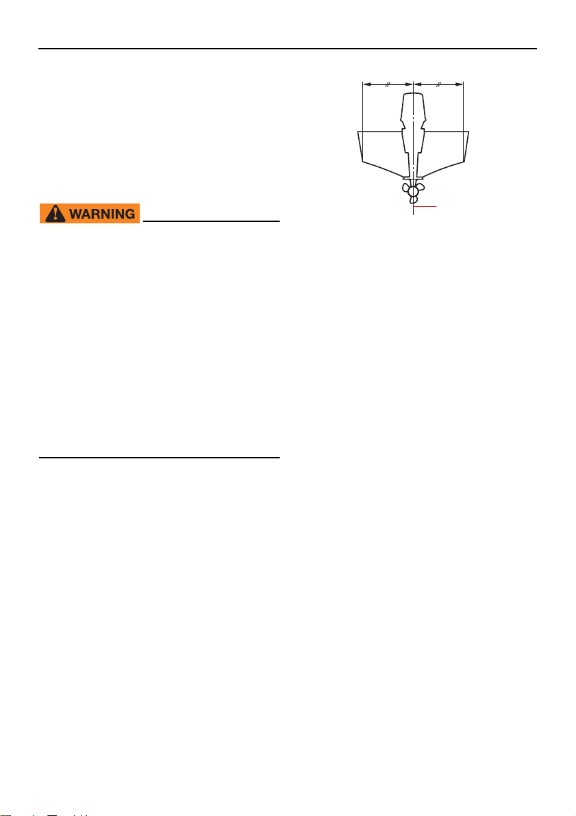
The outboard motor should be mounted so
that the boat is well balanced. Otherwise, the
boat could be hard to steer. For single-engine boats, mount the outboard motor on the
centerline (keel line) of the boat.
1. Center line (keel line)
EMU26937
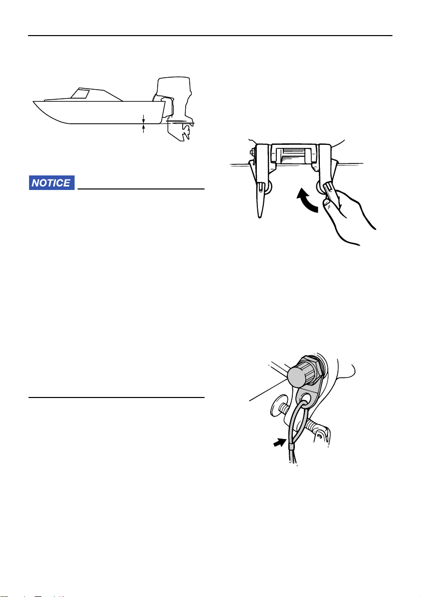
Mounting height (boat bottom)
The mounting height of your outboard motor
affects its efficiency and reliability. If it is
mounted too high, propeller ventilation may
occur, which will reduce propulsion due to
excessive propeller slip, and the water intakes for the cooling system may not get an
adequate water supply, which can cause engine overheating. If the engine is mounted
too low, water resistance (drag) will increase,
thereby reducing engine efficiency and performance.
Most commonly, an outboard motor should
be mounted so that the anti-cavitation plate
is in alignment with the bottom of the boat.
The optimum mounting height of the outboard motor is affected by the boat/motor
combination and the desired use. Test runs
at different heights can help determine the
optimum mounting height. Consult your
Yamaha dealer or boat manufacturer for further information on determining the proper
mounting height.
35
Page 42
Installation
ZMU01762
ZMU02012
ZMU02013
ECM01635
Make sure that the idle hole is high
enough to prevent water from entering
the engine even if the boat is stationary
with the maximum load.
Incorrect engine height or obstructions
to the smooth flow of water (such as the
design or condition of the boat, or accessories, such as transom ladders or
depth finder transducers) can create
airborne water spray while the boat is
cruising. If the outboard motor is operated continuously in the presence of
airborne water spray, enough water
could enter the engine through the air
intake opening in the top cowling to
cause severe engine damage. Remove
the cause of the airborne water spray.
could allow the outboard motor to fall
off or move on the transom. This
could cause loss of control and serious injury. Make sure the clamp
screws are tightened securely. Occasionally check the screws for tightness during operation.
[EWM00643]
(2) If the restraint cable attachment is
equipped on your engine, a restraint cable or chain should be used. Attach one
end to the restraint cable attachment
and the other to a secure mounting point
on the boat. Otherwise the engine could
be completely lost if it accidentally falls
off the transom.
EMU26974
Clamping the outboard motor
(1) Place the outboard motor on the tran-
som so that it is positioned as close to
the center as possible. Tighten the transom clamp screws evenly and securely.
Occasionally check the clamp screws for
tightness during operation of the outboard motor because they could become loose due to engine vibration.
WARNING! Loose clamp screws
36
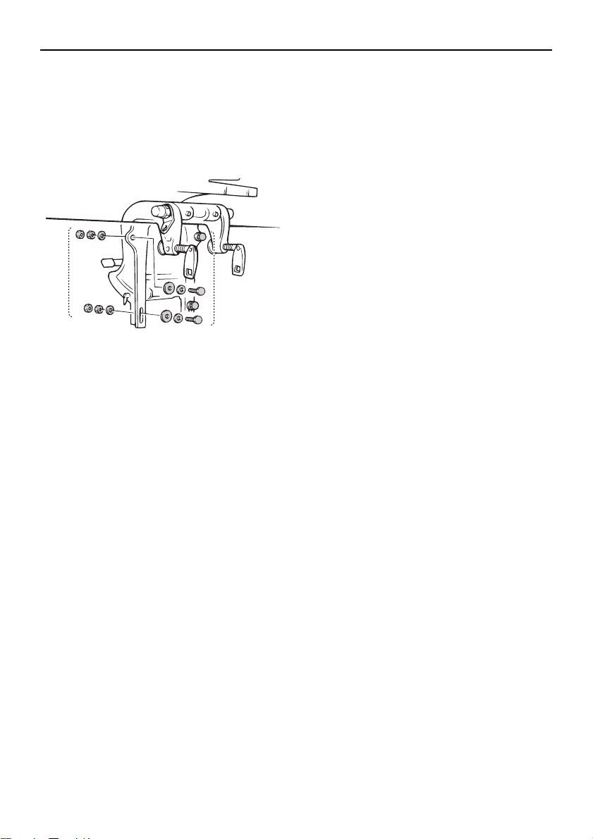
(3) Secure the clamp bracket to the transom
using the bolts provided with the outboard (if packed). For details, consult
your Yamaha dealer. WARNING! Avoid
using bolts, nuts or washers other
than those contained in the engine
Page 43
packaging. If used, they must be of at
ZMU03185
1
1
least the same quality of material and
strength and must be tightened securely. After tightening, test run the
engine and check their tightness.
[EWM00652]
1. Bolts
Installation
37
Page 44
Operation
EMU36382
First-time operation
EMU27023
Breaking in engine
Your new engine requires a period of breakin to allow mating surfaces of moving parts to
wear in evenly. Correct break-in will help ensure proper performance and longer engine
life.
ECM00142
Failure to follow the break-in procedure
could result in reduced engine life or
even severe engine damage.
Premixed fuel must be used during
break-in.
EMU27061
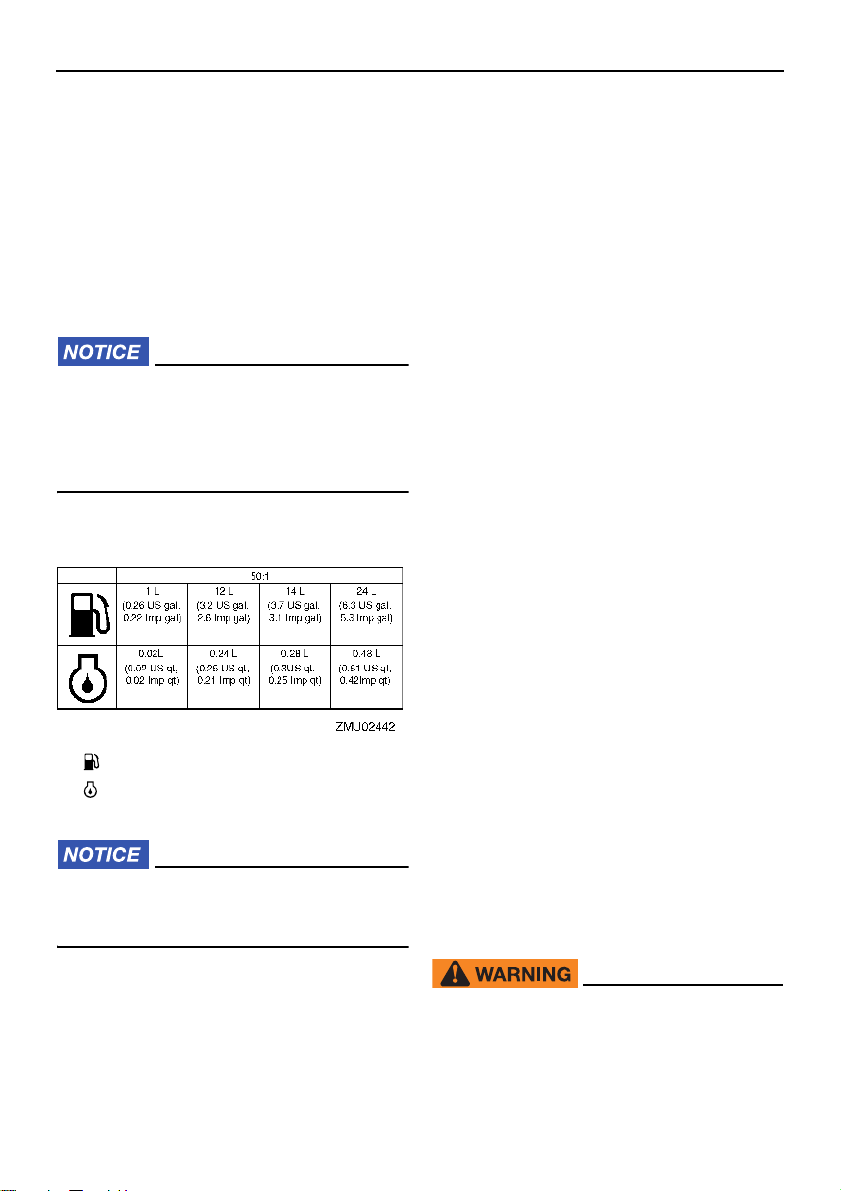
Gasoline and engine oil mixing chart
(50:1)
speed. A fast idle in neutral is best.
(2) Next 50 minutes:
Do not exceed half throttle (approximately 3000 r/min). Vary engine speed
occasionally. If you have an easy-planing boat, accelerate at full throttle onto
plane, then immediately reduce the
throttle to 3000 r/min or less.
(3) Next two hours:
Accelerate at full throttle onto plane,
then reduce engine speed to three-quarter throttle (approximately 4000 r/min).
Vary engine speed occasionally. Run at
full throttle for one minute, then allow
about 10 minutes of operation at threequarter throttle or less to let the engine
cool.
(4) Remaining seven hours:
Run the engine at any speed. However,
avoid operating at full throttle for more
than 5 minutes at a time.
(5) After the first 10 hours:
Operate the engine normally. Use only
straight gasoline in the fuel tank. The
Yamaha oil injection system provides
proper lubrication for normal operation.
1. : Gasoline
2. : Engine oil
ECM00151
Be sure to mix gasoline and oil completely, otherwise the engine may be damaged.
EMU30312
Procedure for oil injection models
Run the engine under load (in gear with a
propeller installed) for 10 hours as follows.
(1) First 10 minutes:
Run the engine at the lowest possible
38
EMU36402
Getting to know your boat
All boats have unique handling characteristics. Operate cautiously while you learn how
your boat handles under different conditions
and various trim angles (see page 55).
EMU36414
Checks before starting engine
EWM01922
If any item in “Checks before starting engine” is not working properly, have it inspected and repaired before operating
the outboard motor. Otherwise, an acci-
Page 45
Operation
ZMU06084
ZMU06150
dent could occur.
ECM00121
Do not start the engine out of water. Overheating and serious engine damage can
occur.
EMU37142
Fuel level
Be sure you have plenty of fuel for your trip.
A good rule is to use 1/3 of your fuel to get to
the destination, 1/3 to return, and to keep 1/3
as an emergency reserve. With the boat level on a trailer or in the water, check the fuel
level. For fuel filling instructions, see page
42.
EMU36573
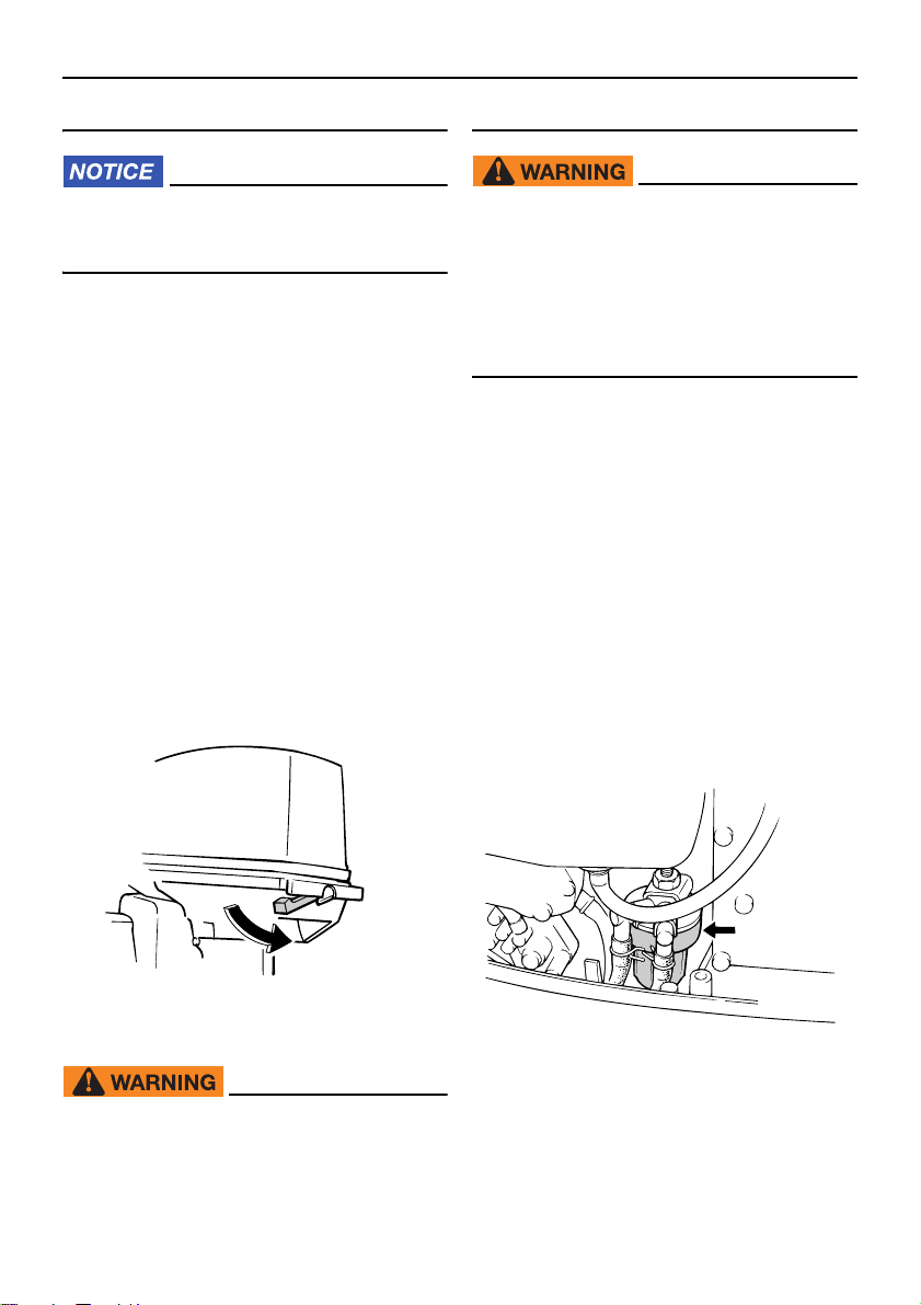
Remove the top cowling
For the following checks, remove the top
cowling from the bottom cowling. To remove
the top cowling, release the cowling lock lever and lift off the top cowling.
es of ignition.
EWM00911
Leaking fuel can result in fire or explosion.
Check for fuel leakage regularly.
If any fuel leakage is found, the fuel
system must be repaired by a qualified
mechanic. Improper repairs can make
the outboard unsafe to operate.
EMU36453
Check for fuel leaks
Check for fuel leaks or gasoline fumes in
the boat.
Check for fuel leakage from the fuel sys-
tem.
Check the fuel tank and fuel lines for
cracks, swellings, or other damage.
EMU37323
Checking the fuel filter
Check that the fuel filter is clean and free of
water. If any water is found in the fuel, or if a
significant amount of debris is found, the fuel
tank should be checked and cleaned by a
Yamaha dealer.
EMU36443
Fuel system
EWM00061
Gasoline and its vapors are highly flammable and explosive. Keep away from
sparks, cigarettes, flames, or other sourc-
EMU36903
Controls
Tiller handle models:
Move the tiller handle fully to the left and
right to make sure operation is smooth.
39
Page 46
Operation
1
2
ZMU03367
Turn the throttle grip from the fully closed
to the fully open position. Make sure that it
turns smoothly and that it completely returns to the fully closed position.
Look for loose or damaged connections of
the throttle and shift cables.
Remote control models:
Turn the steering wheel full-right and full-
left. Make sure operation is smooth and
unrestricted throughout the whole range
with no binding or excessive free play.
Operate the throttle levers several times to
make sure there is no hesitation in their
travel. Operation should be smooth over
the complete range of motion, and each lever should return completely to the idle position.
Look for loose or damaged connections of
the throttle and shift cables.
EMU36484
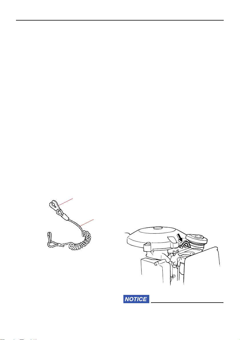
Engine shut-off cord (lanyard)
Inspect the engine shut-off cord and clip for
damage, such as cuts, breaks, and wear.
EMU27154
Engine
Check the engine and engine mounting.
Look for loose or damaged fasteners.
Check the propeller for damage.
Check for engine oil leaks.
EMU27182
Operation after long period of
storage
Oil injection models
When operating the engine after a long period (12 months) of storage, proceed as follows:
(1) Use a 50:1 gasoline to oil mixture to start
the engine.
(2) Start the engine. Leave it idling.
WARNING! Do not touch or remove
electrical parts when starting or during operation. Keep hands, hair, and
clothes away from the flywheel and
other rotating parts while the engine
is running.
(3) Watch for oil flowing through the oil feed
pipes. After any air in the oil lines has
been expelled, the oil injection system
should supply oil normally. If no oil is
flowing after 10 minutes of idling, consult
your Yamaha dealer.
[EWM01332]
1. Clip
2. Engine shut-off cord (lanyard)
EMU27121
Oil
Check to be sure you have plenty of oil for
your trip.
40
ECM01261
Be sure to take the above steps when op-
Page 47
erating the engine after a long period of
ZMU06109
ZMU04678
storage. Otherwise engine seizure could
occur.
EMU36956
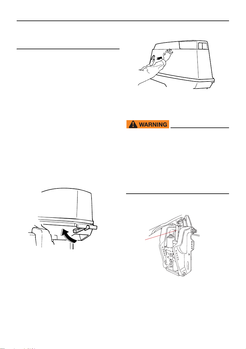
Install top cowling
(1) Be sure that the cowling lock lever is re-
leased.
(2) Be sure that the rubber seal is seated all
the way around the top cowling.
(3) Place the top cowling on the bottom
cowling.
(4) Check to be sure the rubber seal is seat-
ed correctly between the top cowling
and the bottom cowling.
(5) Move the cowling lock lever to lock the
top cowling as shown. NOTICE: If the
top cowling is not installed correctly,
water spray under the top cowling
can damage the engine, or the top
cowling can blow off at high speeds.
[ECM01992]
Operation
EMU34582
Power trim and tilt system
EWM01931
Never get under the lower unit while it
is tilted, even when the tilt support lever
is locked. Severe injury could occur if
the outboard motor accidentally falls.
Body parts can be crushed between the
motor and the clamp bracket when the
motor is trimmed or tilted.
Be sure no one is near the outboard
motor before performing this check.
After installing, check the fitting of the top
cowling by pushing it with both hands. If the
top cowling is loose, have it repaired by your
Yamaha dealer.
(1) Check the power trim and tilt unit for any
sign of oil leaks.
1
ZMU07311
1. Trim and tilt rod
(2) Operate each of the power trim and tilt
switches to check that all switches work.
(3) Tilt the outboard motor up and check
41
Page 48
Operation
ZMU06621
ZMU02301
that the trim and tilt rod is pushed out
completely.
(4) Check that the trim and tilt rod is free of
corrosion or other flaws.
(5) Tilt the outboard motor down. Check that
the trim and tilt rod operates smoothly.
EMU36585
Battery
Check the battery’s charge. If your boat is
equipped with a Yamaha digital speedometer, the voltmeter and low battery alert functions will help you monitor the battery’s
charge. A battery in good condition will provide a minimum of 12 volts. Check that the
battery connections are clean, secure and
covered by insulating covers. The electrical
connections of the battery and cables must
be clean and properly connected or the battery will not start the engine.
If the battery needs charging, consult your
Yamaha dealer or the battery manufacturer’s
instructions.
EMU27235
Filling fuel and engine oil
on your skin, wash with soap and wa-
ter. If gasoline spills on your clothing,
change your clothes.
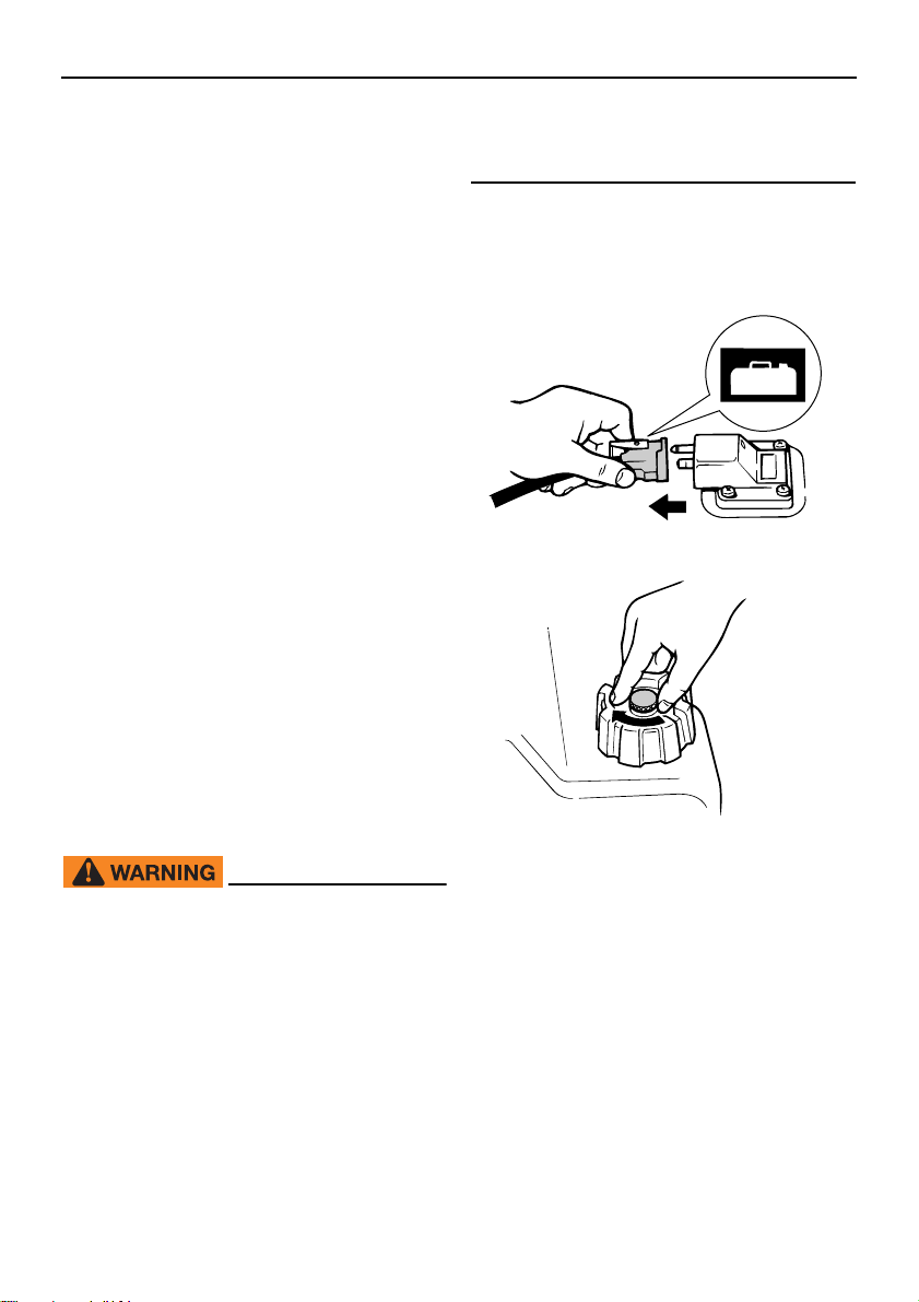
(1) Be sure the engine is stopped.
(2) Disconnect the fuel line from the fuel
tank and tighten the air vent screw on
the fuel tank cap.
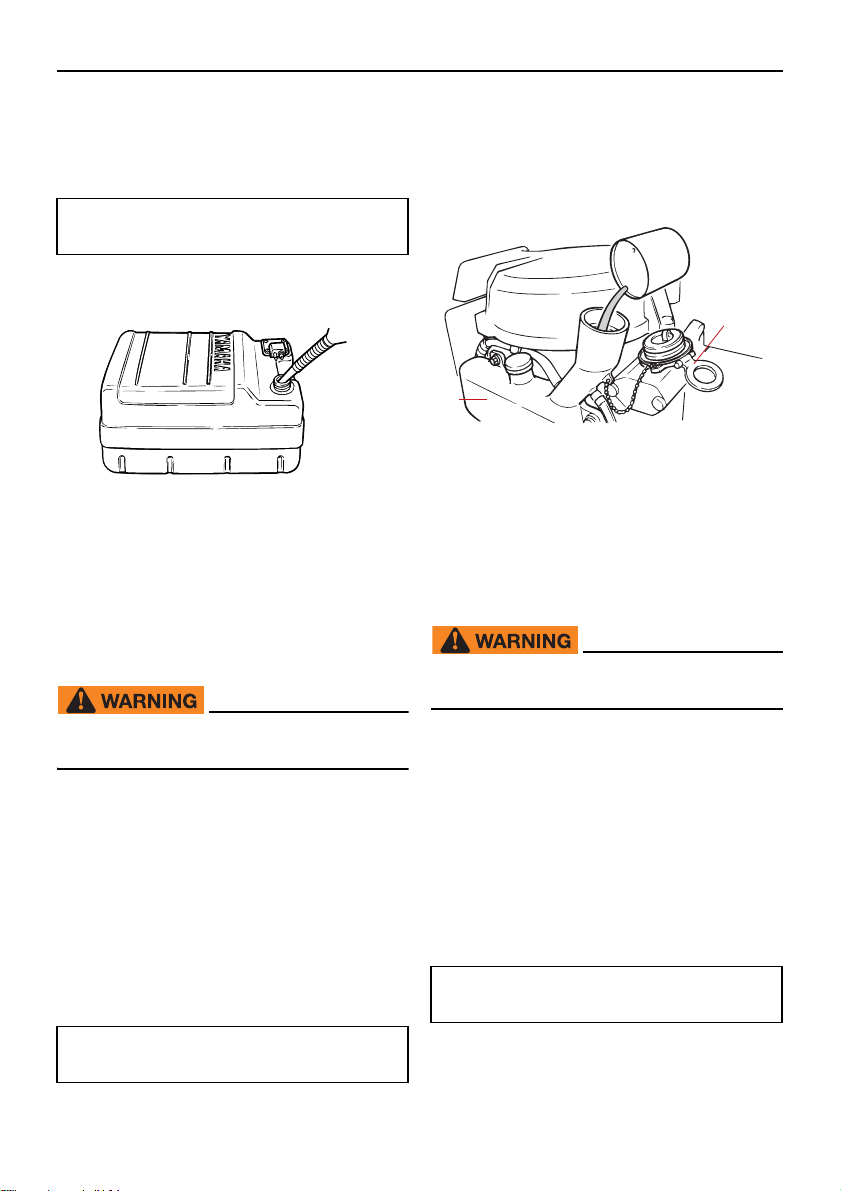
EMU2724A
Filling fuel for portable tank
EWM01831
Gasoline and its vapors are highly flam-
mable and explosive. Always refuel according to this procedure to reduce the
risk of fire and explosion.
Gasoline is poisonous and can cause
injury or death. Handle gasoline with
care. Never siphon gasoline by mouth.
If you should swallow some gasoline or
inhale a lot of gasoline vapor, or get
some gasoline in your eyes, see your
doctor immediately. If gasoline spills
42
(3) Remove the portable tank from the boat.
(4) Be sure you are in a well-ventilated out-
door area, either securely moored or
trailered.
(5) Do not smoke and keep away from
sparks, flames, static electric discharge,
or other sources of ignition.
(6) If you use a portable container to store
and dispense fuel, use only an approved
GASOLINE container.
(7) Touch the fuel nozzle to the filler open-
ing or funnel to help prevent electrostatic
sparks.
Page 49
Operation
ZMU02834
(8) Fill the fuel tank, but do not overfill.
WARNING! Do not overfill. Otherwise
fuel can expand and overflow if the
temperature increases.
[EWM02611]
Fuel tank capacity:
24 L (6.34 US gal, 5.28 Imp.gal)
(9) Tighten the filler cap securely.
(10)Wipe up any spilled gasoline immediate-
ly with dry rags. Dispose of rags properly
according to local laws or regulations.
EMU27302
Filling oil for manual starter model
EWM00531
(1) Remove the top cowling.
(2) Open the oil tank filler cap by pulling the
tab.
(3) Slowly fill the engine oil into the engine
oil tank.
2
1
ZMU03368
1. Engine oil tank
2. Oil tank filler cap
(4) After filling, replace the cap securely.
EMU27312
Filling oil for electric start models
EWM00531
Do not add gasoline into the oil tank. Fire
or explosion could result.
Do not add gasoline into the oil tank. Fire
or explosion could result.
This engine uses the Yamaha oil injection
system, which provides superior lubrication
by ensuring the proper oil ratio for all operating conditions. No fuel premixing is needed.
Simply pour gasoline into the fuel tank and
oil into the oil tank. Convenient indicator segments indicate the status of the oil supply.
For details on reading the indicator segments, see page 45.
To fill the engine oil tank, proceed as follows:
Engine oil tank capacity:
1.5 L (1.59 US qt, 1.32 Imp.qt)
This engine uses the Yamaha oil injection
system, which provides superior lubrication
by ensuring the proper oil ratio for all operating conditions. No fuel premixing is needed.
Simply pour gasoline into the fuel tank and
oil into the oil tank. Convenient indicator segments indicate the status of the oil supply.
For details on reading the indicator segments, see page 45.
To fill the engine oil tank, proceed as follows:
Engine oil tank capacity:
1.5 L (1.59 US qt, 1.32 Imp.qt)
(1) Turn the oil filler access cap on the top
cowling counterclockwise and open it.
43
Page 50
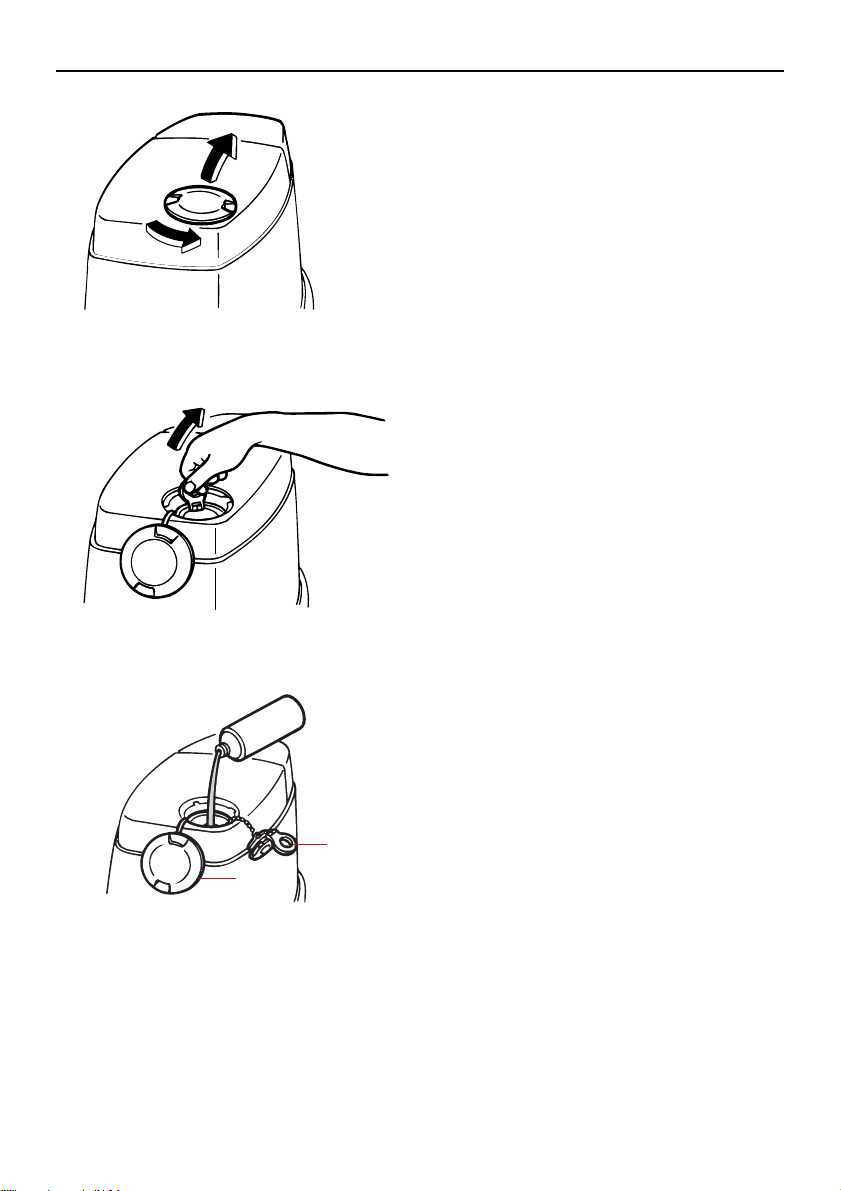
Operation
ZMU03369
ZMU03370
(2) Open the oil tank filler cap by pulling the
tab on the cap.
(3) Slowly pour the engine oil into the en-
gine oil tank.
2
1
1. Oil filler access cap
2. Oil tank filler cap
(4) After filling, replace the all caps secure-
ly.
44
ZMU03371
Page 51
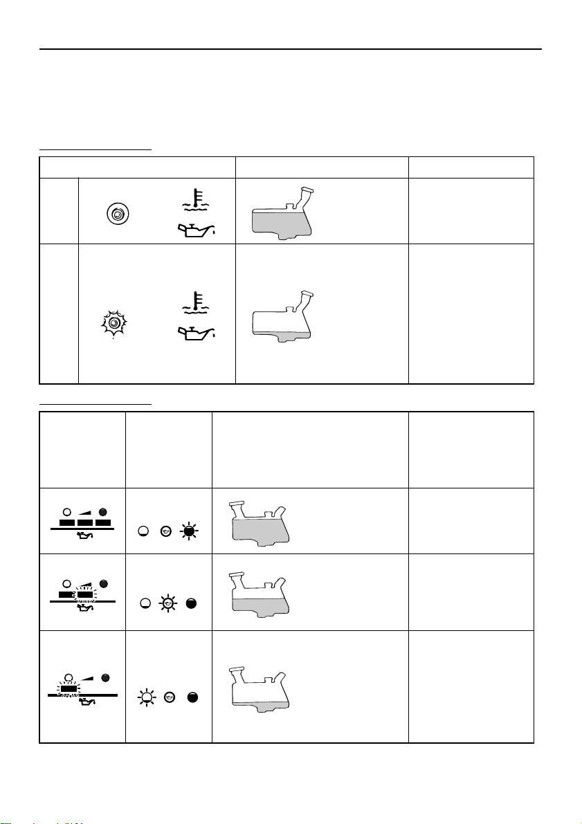
EMU27322
Oil level indicator operation
The various functions of the oil level system are as follows:
EMU27343
Manual start models
Oil level-alert indicator Engine oil tank Remarks
more than
3
OFF
Red
ON
Electric start models
Oil level-alert
indicator
(digital
tachometer)
Oil level-alert
tachometer/
bottom cowling)
indicator
(analog
Green
200 cm
(0.21 US qt,
0.181 Imp qt)
200 cm
(0.21 US qt,
0.181 Imp qt)
or less
Engine oil tank Remarks
more than 450
3
(0.48 US qt,
cm
0.40 Imp qt)
3
Operation
No refilling necessary.
Buzzer sounds in
remote control box
and engine speed is
limited to about 2000
r/min to help conserve oil.
Check oil filter for
clogging.
Add oil; see page
43.
No refilling necessary.
Red
Yellow
3
from 450 cm
(0.48 US qt, 0.40
Imp qt) down to
3
(0.21
200 cm
US qt, 0.18 Imp qt)
3
(0.21
200 cm
US qt, 0.18 Imp qt)
or less
Add oil; see page 43.
Buzzer sounds in
remote control box
and engine speed is
limited to about 2000
r/min to help conserve oil.
Check oil filter for
clogging.
45
Page 52
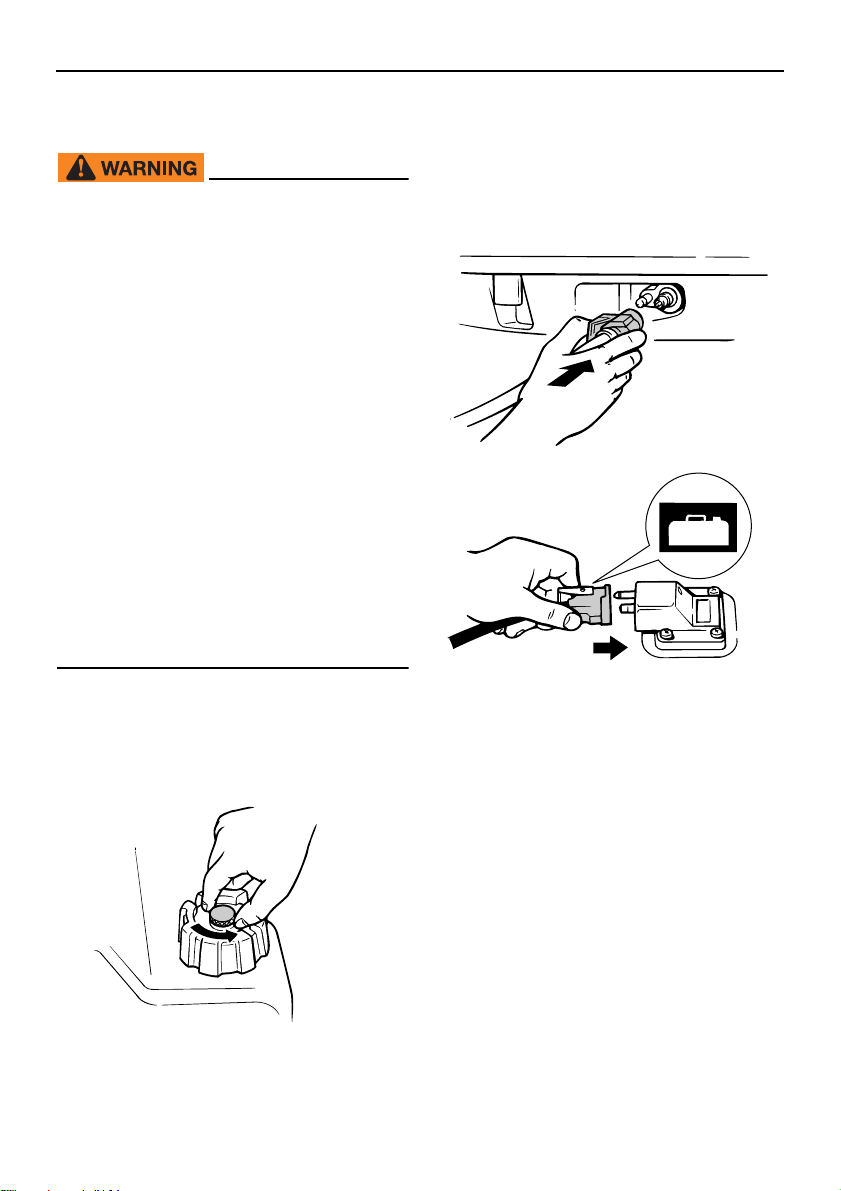
Operation
TIP:
ZMU02295
ZMU03100
ZMU02024
EMU27453
Operating engine
EWM00421
Before starting the engine, make sure
that the boat is tightly moored and that
you can steer clear of any obstructions.
Be sure there are no swimmers in the
water near you.
When the air vent screw is loosened,
gasoline vapor will be released. Gasoline is highly flammable, and its vapors
are flammable and explosive. Refrain
from smoking, and keep away from
open flames and sparks while loosening the air vent screw.
This product emits exhaust gases
which contain carbon monoxide, a colorless, odorless gas which could cause
brain damage or death when inhaled.
Symptoms include nausea, dizziness,
and drowsiness. Keep cockpit and cabin areas well ventilated. Avoid blocking
exhaust outlets.
joint on the motor and firmly connect the
fuel line to the joint while pinching the
joint. Then firmly connect the other end
of the fuel line to the joint on the fuel
tank.
EMU35706
Sending fuel (portable tank)
(1) If there is an air vent screw on the fuel
tank cap, loosen it 2 or 3 turns.
(2) If there is a fuel joint on the motor, align
the fuel joint on the fuel line with the fuel
46
Wipe up any spilled gasoline immediately
with dry rags. Dispose rags properly according to local laws or regulations.
(3) If a steering friction adjuster is provided
on your outboard motor, securely attach
the fuel line to the fuel line clamp.
(4) Squeeze the primer pump, with the ar-
row pointing up, until you feel it become
firm. During engine operation place the
tank horizontally, otherwise fuel cannot
be drawn from the fuel tank.
Page 53
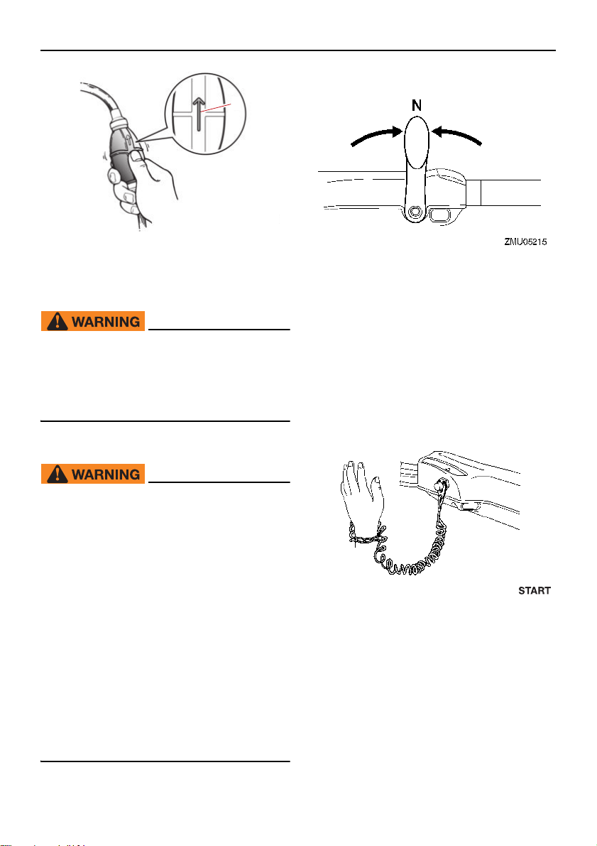
TIP:
1. Arrow
1
ZMU07329
Operation
(1) Place the gear shift lever in neutral.
EMU27495
Starting engine
EWM01601
Before starting the engine, make sure
that the boat is tightly moored and that
you can steer clear of any obstructions.
Be sure there are no swimmers in the water near you.
EMU2750A
Manual start models (tiller control)
EWM01842
Failure to attach the engine shut-off
cord could result in a runaway boat if
operator is ejected. Attach the engine
shut-off cord to a secure place on your
clothing, or your arm or leg while operating. Do not attach the cord to clothing
that could tear loose. Do not route the
cord where it could become entangled,
preventing it from functioning.
Avoid accidentally pulling the cord dur-
ing normal operation. Loss of engine
power means the loss of most steering
control. Also, without engine power,
the boat could slow rapidly. This could
cause people and objects in the boat to
be thrown forward.
The start-in-gear protection device prevents
the engine from starting except when in neutral.
(2) Attach the engine shut-off cord to a se-
cure place on your clothing, or your arm
or leg. Then install the clip on the other
end of the cord into the engine shut-off
switch.
(3) Place the throttle grip in the “ ”
(start) position.
47
Page 54
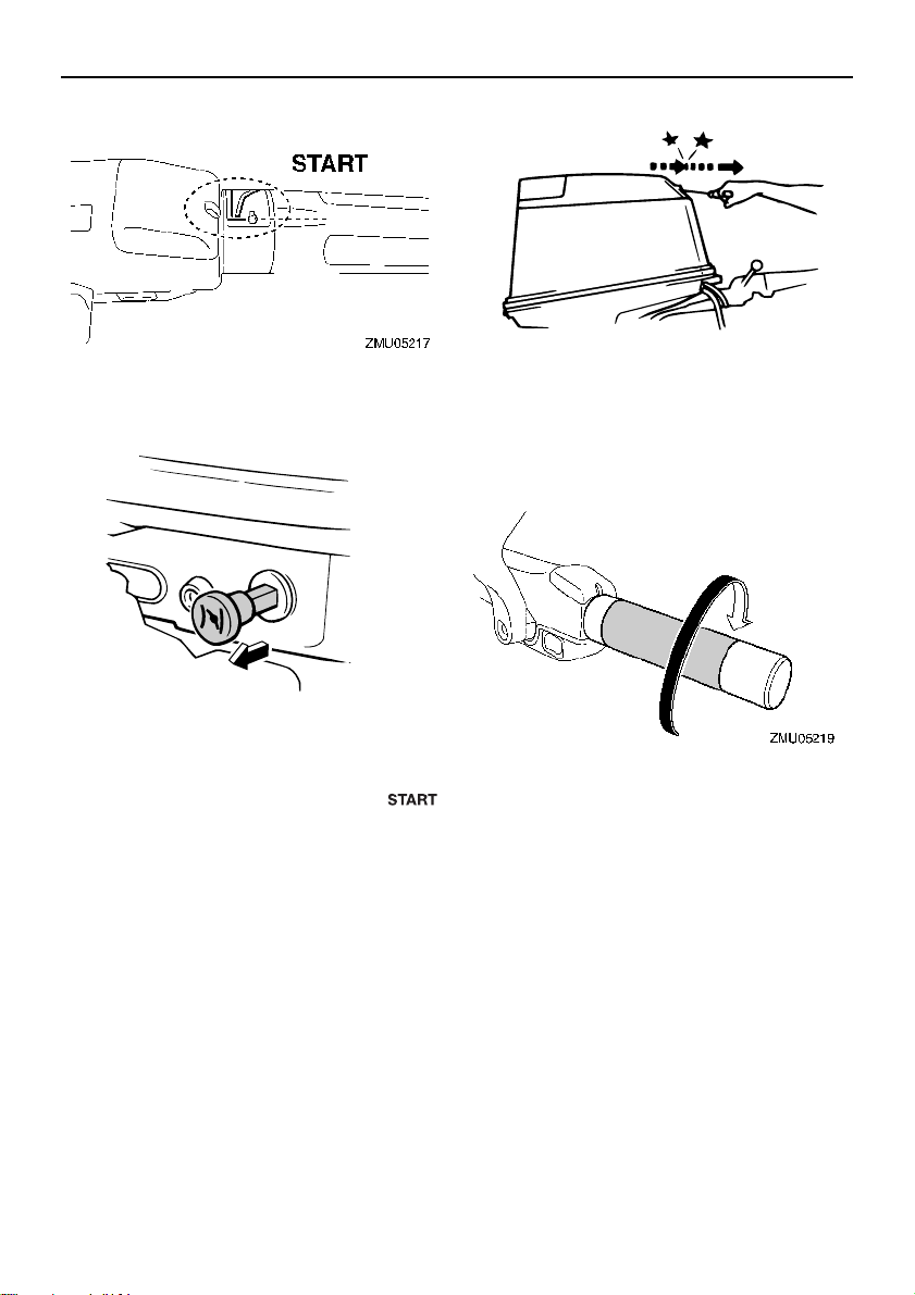
Operation
TIP:
TIP:
ZMU03389
ZMU03279
(4) Pull out / turn the choke knob fully. After
the engine starts, replace / return the
knob to the home position.
It is not necessary to use the choke when
starting a warm engine.
If the choke knob is left in the “ ”
(start) position while the engine is running,
the engine will run poorly or stall.
(5) Pull the manual starter handle slowly un-
til you feel resistance. Then give a
strong pull straight out to crank and start
the engine. Repeat if necessary.
(6) After the engine starts, slowly return the
manual starter handle to its original position before releasing it.
(7) Slowly return the throttle grip to the fully
closed position.
When the engine is cold, it needs to be
warmed up. For further information, see
page 51.
If the engine does not start on the first try,
repeat the procedure. If the engine fails to
start after 4 or 5 tries, open the throttle a
small amount (between 1/8 and 1/4) and
try again. Also if the engine is warm and
fails to start, open the throttle a same
amount and try to start the engine again. If
the engine still fails to start, see page 80.
48
Page 55
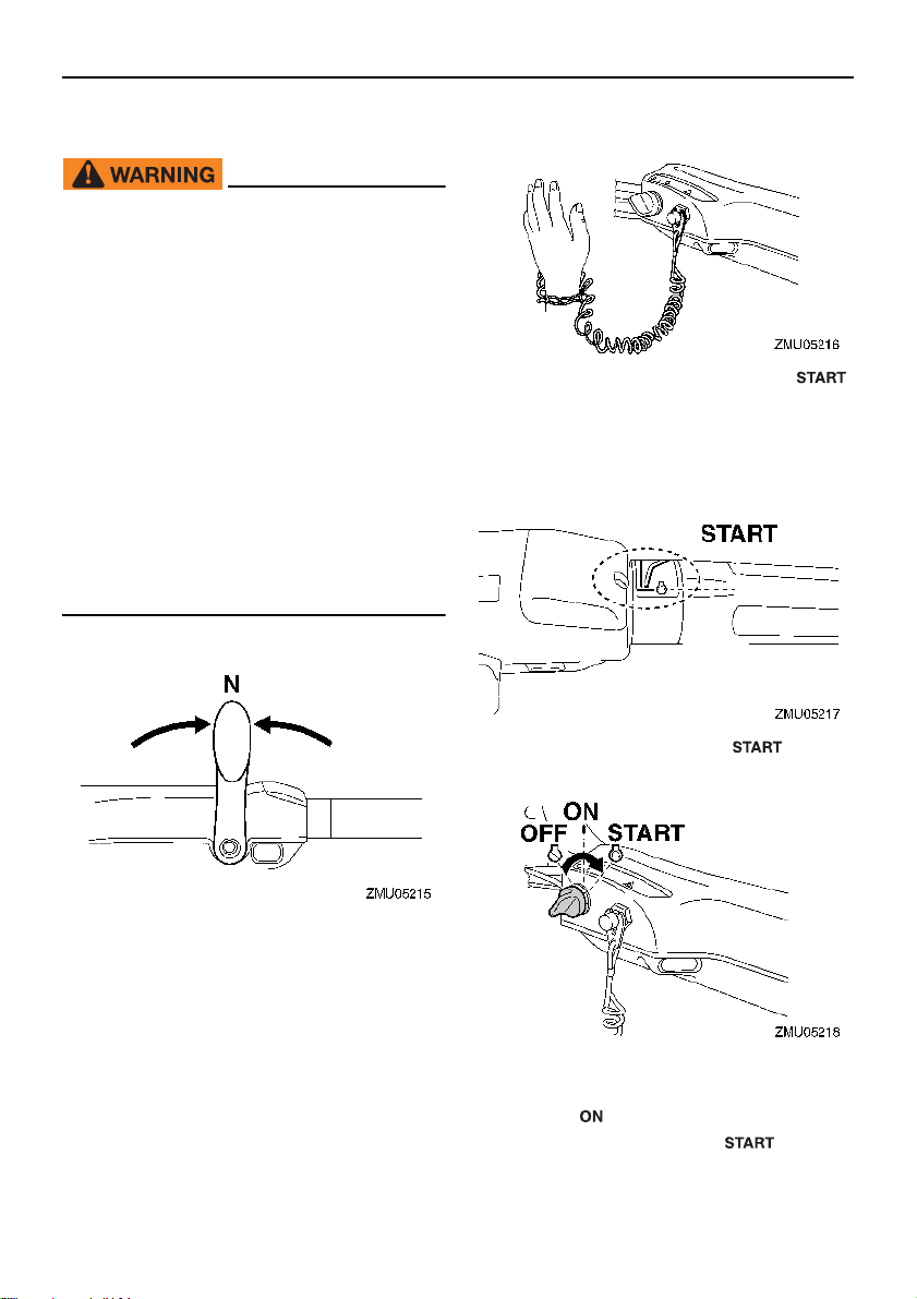
EMU27597
TIP:
Electric start / prime start models
EWM01842
Failure to attach the engine shut-off
cord could result in a runaway boat if
operator is ejected. Attach the engine
shut-off cord to a secure place on your
clothing, or your arm or leg while operating. Do not attach the cord to clothing
that could tear loose. Do not route the
cord where it could become entangled,
preventing it from functioning.
Avoid accidentally pulling the cord dur-
ing normal operation. Loss of engine
power means the loss of most steering
control. Also, without engine power,
the boat could slow rapidly. This could
cause people and objects in the boat to
be thrown forward.
(1) Place the gear shift lever in neutral.
Operation
(3) Place the throttle grip in the “ ”
(start) position. After the engine starts,
return the throttle to the fully closed position.
The start-in-gear protection device prevents
the engine from starting except when in neutral.
(2) Attach the engine shut-off cord to a se-
cure place on your clothing, or your arm
or leg. Then install the clip on the other
end of the cord into the engine shut-off
switch.
(4) Turn the main switch to “ ” (start),
and hold it for a maximum of 5 seconds.
(5) Immediately after the engine starts, re-
lease the main switch and allow it to return to “ ” (on). NOTICE: Never turn
the main switch to “ ” (start)
while the engine is running. Do not
49
Page 56
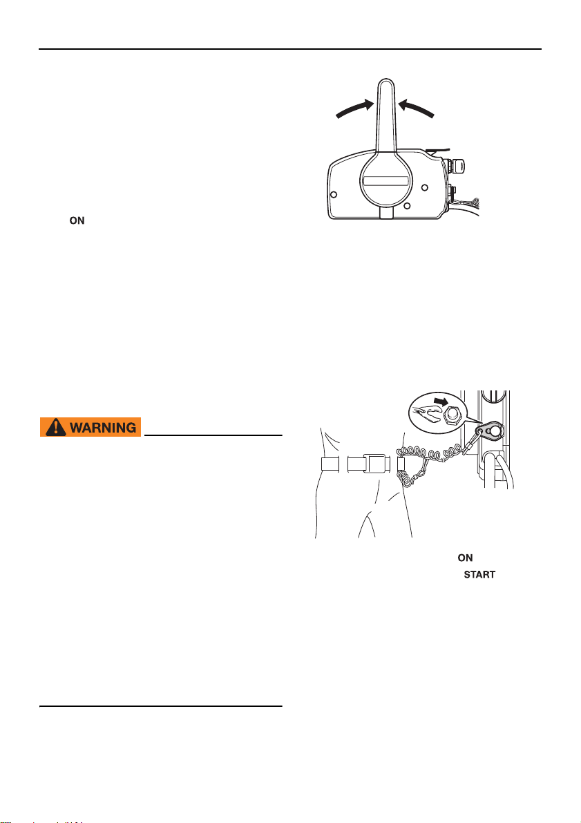
Operation
TIP:
TIP:
N
ZMU01771
keep the starter motor turning for
more than 5 seconds. If the starter
motor is turned continuously for
more than 5 seconds, the battery will
be quickly discharged, thus making it
impossible to start the engine. The
starter can also be damaged. If the
engine will not start after 5 seconds
of cranking, return the main switch to
“ ” (on), wait 10 seconds, then
crank the engine again.
When the engine is cold, it needs to be
warmed up. For further information, see
page 51.
If the engine is warm and fails to start,
open the throttle slightly and try to start the
engine again. If the engine still fails to
start, see page 80.
EMU27666
Electric start and remote control models
EWM01842
[ECM00193]
The start-in-gear protection device prevents
the engine from starting except when in neutral.
(2) Attach the engine shut-off cord to a se-
cure place on your clothing, or your arm
or leg. Then install the clip on the other
end of the cord into the engine shut-off
switch.
Failure to attach the engine shut-off
cord could result in a runaway boat if
operator is ejected. Attach the engine
shut-off cord to a secure place on your
clothing, or your arm or leg while operating. Do not attach the cord to clothing
that could tear loose. Do not route the
cord where it could become entangled,
preventing it from functioning.
Avoid accidentally pulling the cord dur-
ing normal operation. Loss of engine
power means the loss of most steering
control. Also, without engine power,
the boat could slow rapidly. This could
cause people and objects in the boat to
be thrown forward.
(1) Place the remote control lever in neutral.
50
ZMU01772
(3) Turn the main switch to “ ” (on).
(4) Turn the main switch to “ ” (start),
and hold it for a maximum of 5 seconds.
Page 57
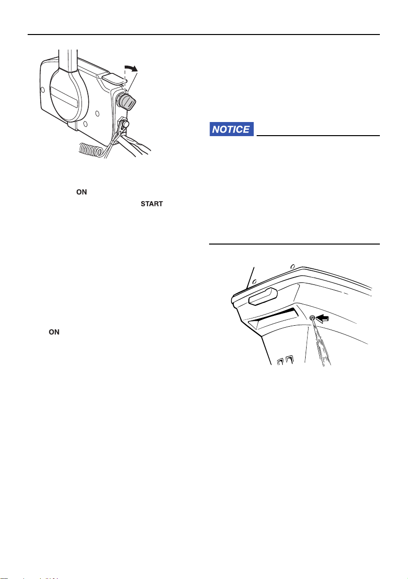
(5) Immediately after the engine starts, re-
TIP:
ON
START
ZMU01774
ZMU03391
lease the main switch and allow it to return to “ ” (on). NOTICE: Never turn
the main switch to “ ” (start)
while the engine is running. Do not
keep the starter motor turning for
more than 5 seconds. If the starter
motor is turned continuously for
more than 5 seconds, the battery will
be quickly discharged, thus making it
impossible to start the engine. The
starter can also be damaged. If the
engine will not start after 5 seconds
of cranking, return the main switch to
“ ” (on), wait 10 seconds, then
crank the engine again.
[ECM00193]
Operation
cooling water pilot hole. A continuous flow of
water from the pilot hole indicates that the
water pump is pumping water through the
cooling water passages. If the cooling water
passages are frozen, it may take a while for
water to start flowing out of the pilot hole.
ECM01811
If water is not flowing out of the pilot hole
at all times while the engine is running,
overheating and serious damage could
occur. Stop the engine and check whether the cooling water inlet on the lower
case or the cooling water pilot hole is
blocked. Consult your Yamaha dealer if
the problem cannot be located and corrected.
When the engine is cold, it needs to be
warmed up. For further information, see
page 51.
If the engine is warm and fails to start,
open the throttle slightly and try to start the
engine again. If the engine still fails to
start, see page 80.
EMU36511
Checks after starting engine
EMU36524
Cooling water
Check for a steady flow of water from the
EMU27671
Warming up engine
EMU27685
Choke start models
After starting the engine, allow it to idle for 3
minutes to warm up. NOTICE: Failure to do
so will shorten engine life.
ly return the choke knob to its home position
as the engine warms up.
[ECM04550] Gradual-
51
Page 58
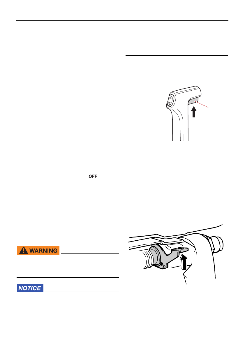
Operation
ZMU03399
EMU27705
Electric start and prime start models
After starting the engine, allow it to idle for 3
minutes to warm up. Failure to do so will
shorten engine life.
EMU36532
Checks after engine warm up
EMU36542
Shifting
While the boat is tightly moored, and without
applying throttle, confirm that the engine
shifts smoothly into forward and reverse, and
back to neutral.
EMU40461
Stop switches
Perform the following procedure to check
that the main switch and engine shut-off
switch operate properly.
Check that the engine stops when the
main switch is turned to the “ ” (off) position.
Check that the engine stops when the clip
is pulled from the engine shut-off switch.
Check that the engine cannot be started
with the clip removed from the engine
shut-off switch.
idle speed can prevent you from shifting
back to neutral. If this occurs, stop the
engine, shift to neutral, then restart the
engine and allow it to warm up.
To shift out of neutral
(1) Pull the neutral interlock trigger up (if
equipped).
1
ZMU01727
1. Neutral interlock trigger
(2) Move the remote control lever / gear
shift lever firmly and crisply forward (for
forward gear) or backward (for reverse
gear) [about 35 (a detent can felt) for remote control models]. Be sure to check
that the tilt lock lever is in the lock/down
position (if equipped) before operating in
reverse.
EMU34531
Shifting
EWM00181
Before shifting, make sure there are no
swimmers or obstacles in the water near
you.
ECM01611
Warm up the engine before shifting into
gear. Until the engine is warm, the idle
speed may be higher than normal. High
52
Page 59
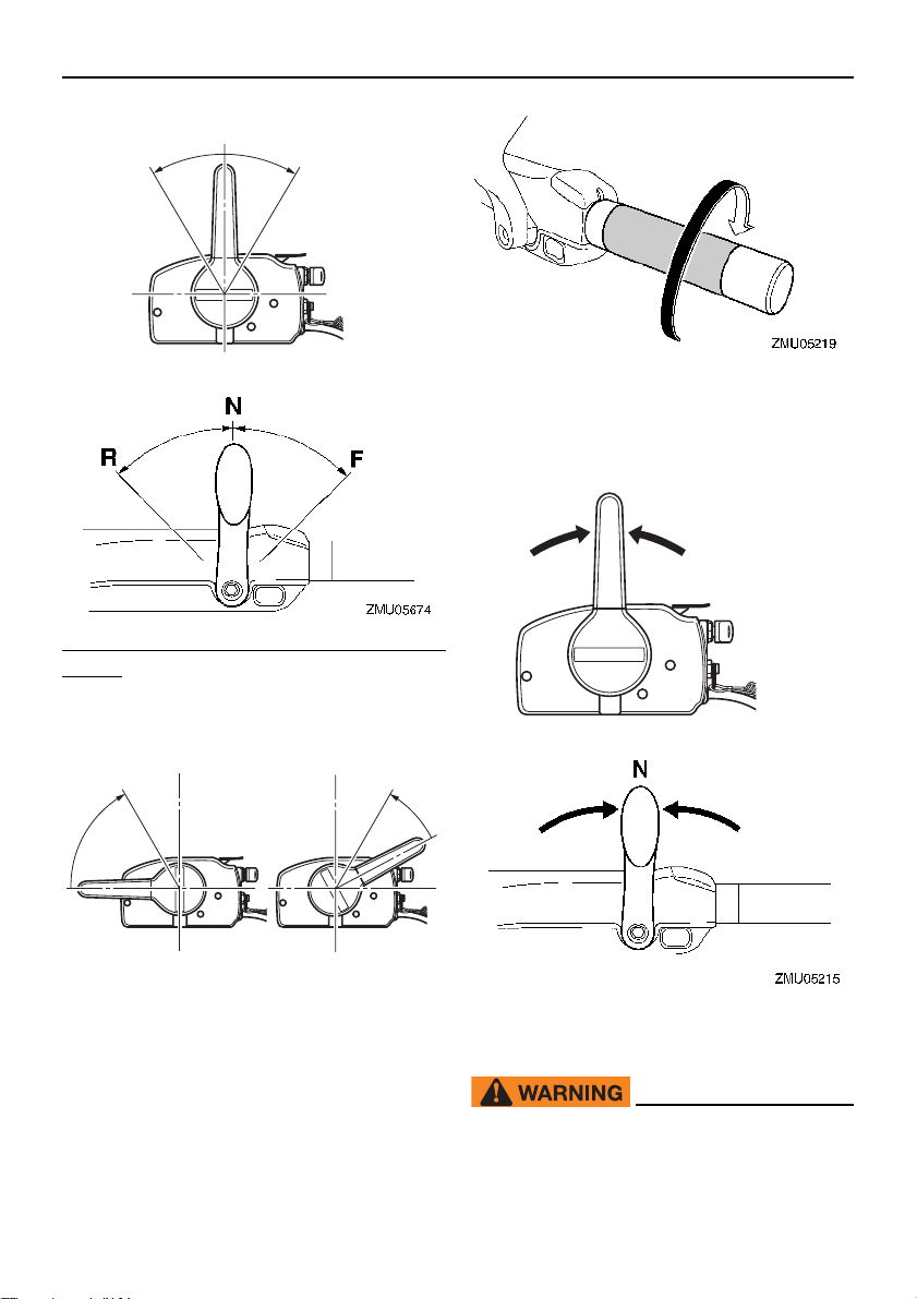
To shift from in gear (forward/reverse) to
F
N
R
32˚
32˚
ZMU05460
RF
ZMU05462
N
ZMU01771
neutral
(1) Close the throttle so that the engine
slows to idle speed.
Operation
(2) After the engine is at idle speed in gear
move the remote control lever / gear
shift lever firmly and crisply into the neutral position.
EMU31743
Stopping boat
EWM01511
Do not use the reverse function to slow
down or stop the boat as it could cause
53
Page 60
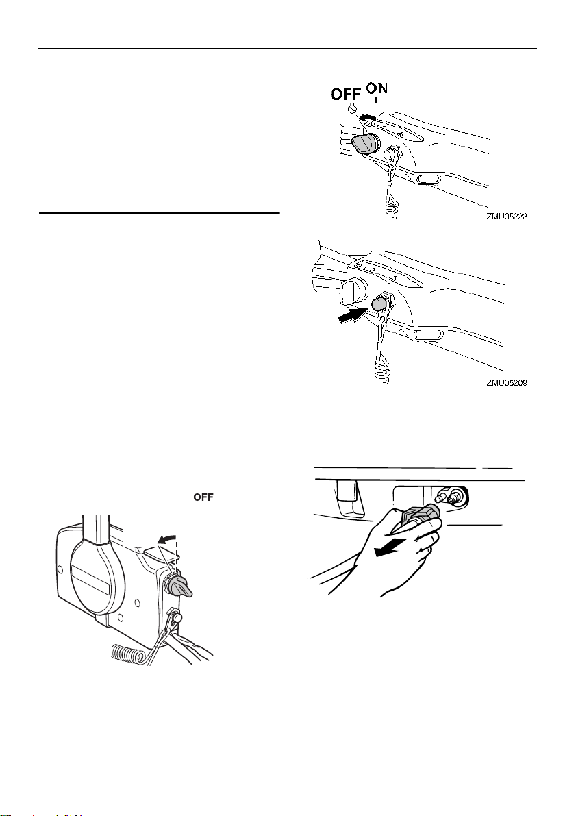
Operation
ZMU03108
you to lose control, be ejected, or impact the steering wheel or other parts of
the boat. This could increase the risk of
serious injury. It could also damage the
shift mechanism.
Do not shift into reverse while traveling
at planing speeds. Loss of control, boat
swamping, or damage to the boat could
occur.
The boat is not equipped with a separate
braking system. Water resistance stops it after the throttle lever is moved back to idle.
The stopping distance varies depending on
gross weight, water surface conditions, and
wind direction.
EMU27822
Stopping engine
Before stopping the engine, first let it cool off
for a few minutes at idle or low speed. Stopping the engine immediately after operating
at high speed is not recommended.
EMU2784A
Procedure
(1) Push and hold the engine stop button or
turn the main switch to “ ” (off).
(2) After stopping the engine, disconnect
the fuel line if there is a fuel joint on the
outboard motor.
54
OFF
ON
(3) Tighten the air vent screw on the fuel
tank cap (if equipped).
ZMU01779
Page 61
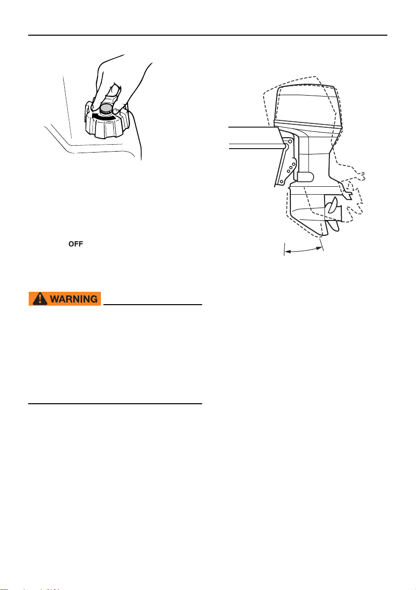
(4) Remove the key if the boat will be left un-
TIP:
ZMU02301
attended.
The engine can also be stopped by pulling
the cord and removing the clip from the engine shut-off switch, then turning the main
switch to “ ” (off).
EMU27865
Trimming outboard motor
EWM00741
Operation
1
ZMU03109
1. Trim operating angle
Excessive trim for the operating conditions (either trim up or trim down) can
cause boat instability and can make
steering the boat more difficult. This increases the possibility of an accident. If
the boat begins to feel unstable or is hard
to steer, slow down and/or readjust the
trim angle.
The trim angle of the outboard motor helps
determine the position of the bow of the boat
in the water. Correct trim angle will help improve performance and fuel economy while
reducing strain on the engine. Correct trim
angle depends upon the combination of
boat, engine, and propeller. Correct trim is
also affected by variables such as the load in
the boat, sea conditions, and running speed.
EMU27873
Adjusting trim angle for manual tilt
models
There are 4 or 5 holes provided in the clamp
bracket to adjust the outboard motor trim angle.
(1) Stop the engine.
(2) Tilt the outboard motor up, and then re-
move the trim rod from the clamp bracket.
55
Page 62
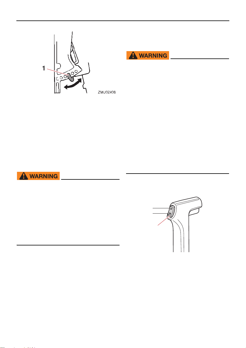
Operation
TIP:
111
DN
UP
1
ZMU01781
1. Trim rod
(3) Reposition the rod in the desired hole.
To raise the bow (“trim-out”), move the rod
away from the transom.
To lower the bow (“trim-in”), move the rod toward the transom.
Make test runs with the trim set to different
angles to find the position that works best for
your boat and operating conditions.
EWM00401
Stop the engine before adjusting the
trim angle.
Use care to avoid being pinched when
removing or installing the rod.
Use caution when trying a trim position
for the first time. Increase speed gradually and watch for any signs of instability or control problems. Improper trim
angle can cause loss of control.
EMU27889
Adjusting trim angle (Power trim and
tilt)
EWM00754
Be sure all people are clear of the out-
board motor when adjusting the trim
angle. Body parts can be crushed be-
tween the motor and the clamp bracket
when the motor is trimmed or tilted.
Use caution when trying a trim position
for the first time. Increase speed gradu-
ally and watch for any signs of instabil-
ity or control problems. Improper trim
angle can cause loss of control.
If equipped with a power trim and tilt
switch located on the bottom cowling,
use the switch only when the boat is at
a complete stop with the engine off. Do
not adjust the trim angle with this
switch while the boat is moving.
Adjust the outboard motor trim angle using
the power trim and tilt switch.
The outboard motor trim angle can be
changed approximately 4 degrees by shifting
the trim rod one hole.
56
1. Power trim and tilt switch
Page 63
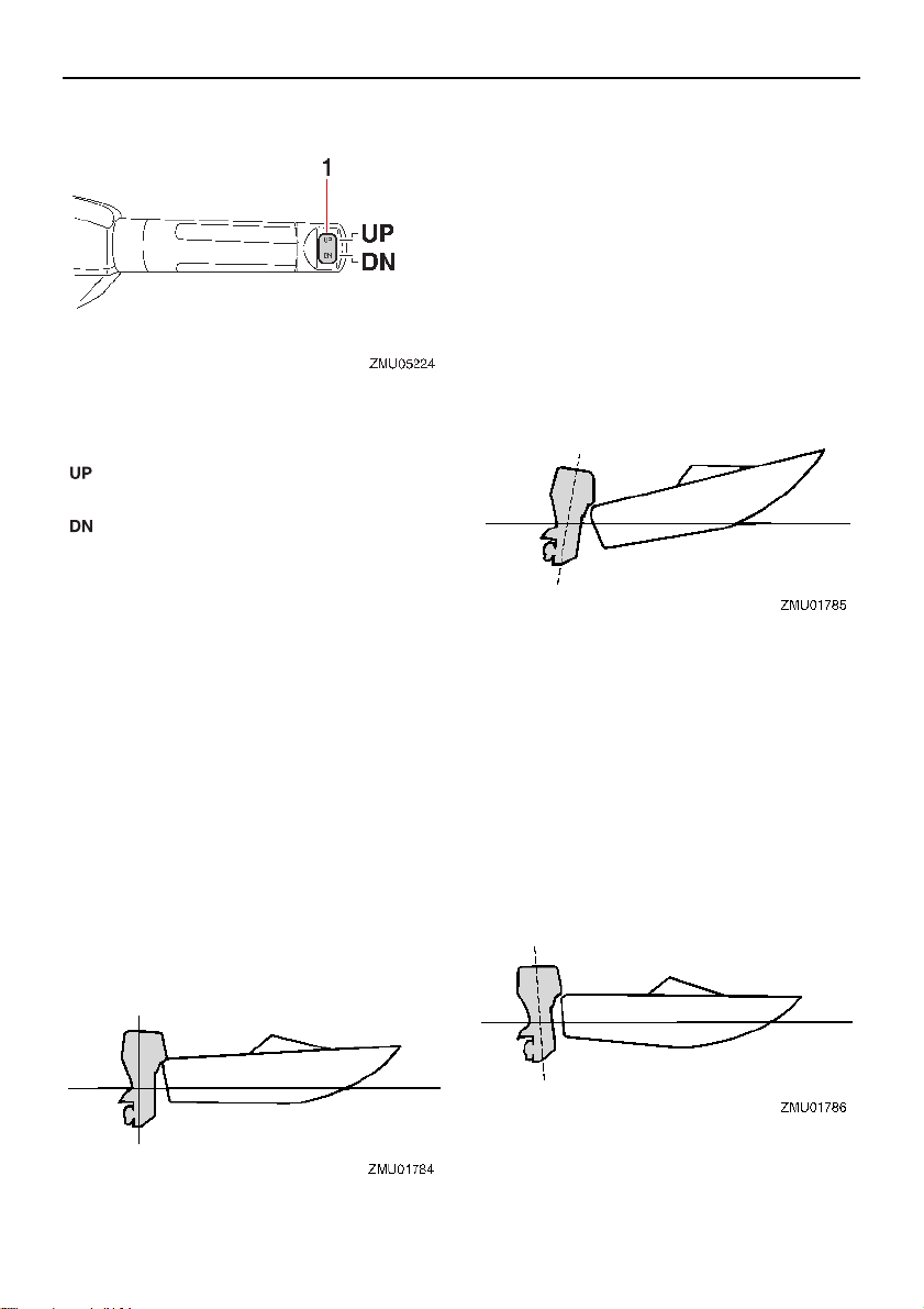
TIP:
1. Power trim and tilt switch
11
To raise the bow (trim-out), press the switch
“ ” (up).
To lower the bow (trim-in), press the switch
“ ” (down).
Make test runs with the trim set to different
angles to find the position that works best for
your boat and operating conditions.
EMU27913
Adjusting boat trim
When the boat is on plane, a bow-up attitude
results in less drag, greater stability and efficiency. This is generally when the keel line of
the boat is up about 3 to 5 degrees. With the
bow up, the boat may have a greater tendency to steer to one side or the other. Compensate for this as you steer. When the bow of
the boat is down, it is easier to accelerate
from a standing start onto plane.
Operation
Bow Up
Too much trim-out puts the bow of the boat
too high in the water. Performance and economy are decreased because the hull of the
boat is pushing the water and there is more
air drag. Excessive trim-out can also cause
the propeller to ventilate, which reduces performance further, and the boat may “porpoise” (hop in the water), which could throw
the operator and passengers overboard.
Bow Down
Too much trim-in causes the boat to “plow”
through the water, decreasing fuel economy
and making it hard to increase speed. Operating with excessive trim-in at higher speeds
also makes the boat unstable. Resistance at
the bow is greatly increased, heightening the
danger of “bow steering” and making operation difficult and dangerous.
Depending on the type of boat, the outboard
57
Page 64
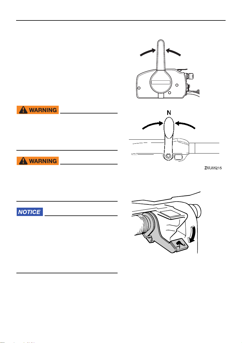
Operation
N
ZMU01771
ZMU03405
motor trim angle may have little effect on the
trim of the boat when operating.
EMU27936
Tilting up and down
If the engine will be stopped for some time or
if the boat is moored in shallows, the outboard motor should be tilted up to protect the
propeller and lower casing from damage by
collision with obstructions, and also to reduce salt corrosion.
EWM00223
Make sure that no one is near the outboard motor when tilting the outboard
motor up or down. Otherwise, body parts
could be crushed between the outboard
motor and the clamp bracket.
EWM00251
Leaking fuel is a fire hazard. If there is a
fuel joint on the outboard motor, disconnect the fuel line or close the fuel cock if
the engine will be tilted for more than a
few minutes. Otherwise fuel may leak.
ECM00242
shift lever in neutral.
(2) Place the tilt lock lever in the release po-
sition.
Before tilting the outboard motor, stop
the engine by following the procedure
on page 54. Never tilt the outboard motor while the engine is running. Severe
damage from overheating can result.
Do not tilt up the engine by pushing the
tiller handle (if equipped) because this
could break the handle.
EMU27956
Procedure for tilting up (manual tilt
models)
(1) Place the remote control lever / gear
58
(3) Hold the rear of the top cowling with one
hand, tilt the engine up, and turn the tilt
support lever to the lock position and
support the engine. NOTICE: Do not
use the tilt support lever or knob
when trailering the boat. The outboard motor could shake loose from
the tilt support and fall. If the motor
Page 65
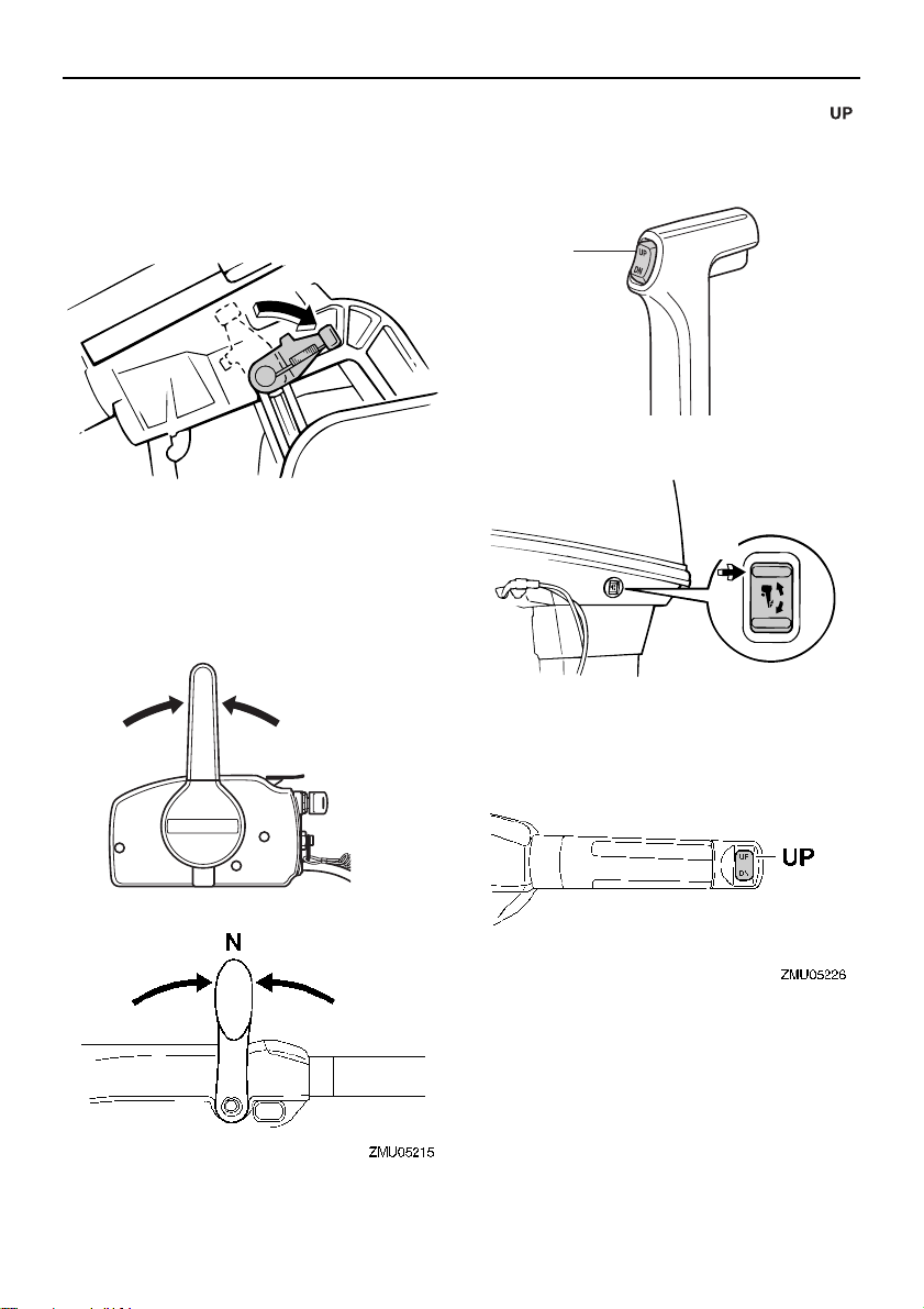
Operation
ZMU03358
N
ZMU01771
UP
ZMU01935
UP
ZMU04993
cannot be trailered in the normal running position, use an additional support device to secure it in the tilt
position. For more detailed information, see page 63.
EMU42693
[ECM01642]
Procedure for tilting up (power trim
and tilt models)
(1) Place the remote control lever / gear
shift lever in neutral.
(2) Press the power trim and tilt switch “ ”
(up) until the outboard motor has tilted
up completely.
(3) Pull the tilt support lever toward you to
support the engine. WARNING! After
tilting the outboard motor, be sure to
support it with the tilt support knob or
tilt support lever. Otherwise the outboard motor could fall back down
suddenly if oil in the power trim and
59
Page 66
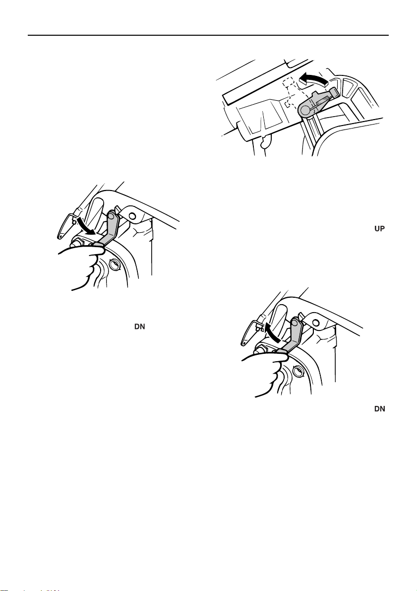
Operation
ZMU03115
ZMU06644
ZMU02569
tilt unit or in the power tilt unit loses
pressure.
the tilt support lever or knob when
trailering the boat. The outboard motor could shake loose from the tilt
support and fall. If the motor cannot
be trailered in the normal running position, use an additional support device to secure it in the tilt position.
For more detailed information, see
page 63.
(4) Once the outboard motor is supported
with the tilt support lever, press the power trim and tilt switch “ ” (down) to retract the trim rods. NOTICE: Make sure
that the trim rods retract completely
during mooring. This protects the
rods from marine growth and corrosion, which could damage the power
trim and tilt mechanism.
EMU30412
Procedure for tilting down (manual
tilt models)
(1) Slightly tilt the engine up.
(2) On models equipped with a tilt support
lever, return it to the release position.
[EWM00263] NOTICE: Do not use
[ECM01642]
[ECM00254]
(3) Slowly tilt the engine down.
EMU35517
Procedure for tilting down (power
trim and tilt models)
(1) Push the power trim and tilt switch “ ”
(up) until the outboard motor is supported by the tilt rod and the tilt support lever
becomes free.
(2) Release the tilt support lever.
(3) Push the power trim and tilt switch “ ”
(down) to lower the outboard motor to
the desired position.
60
Page 67
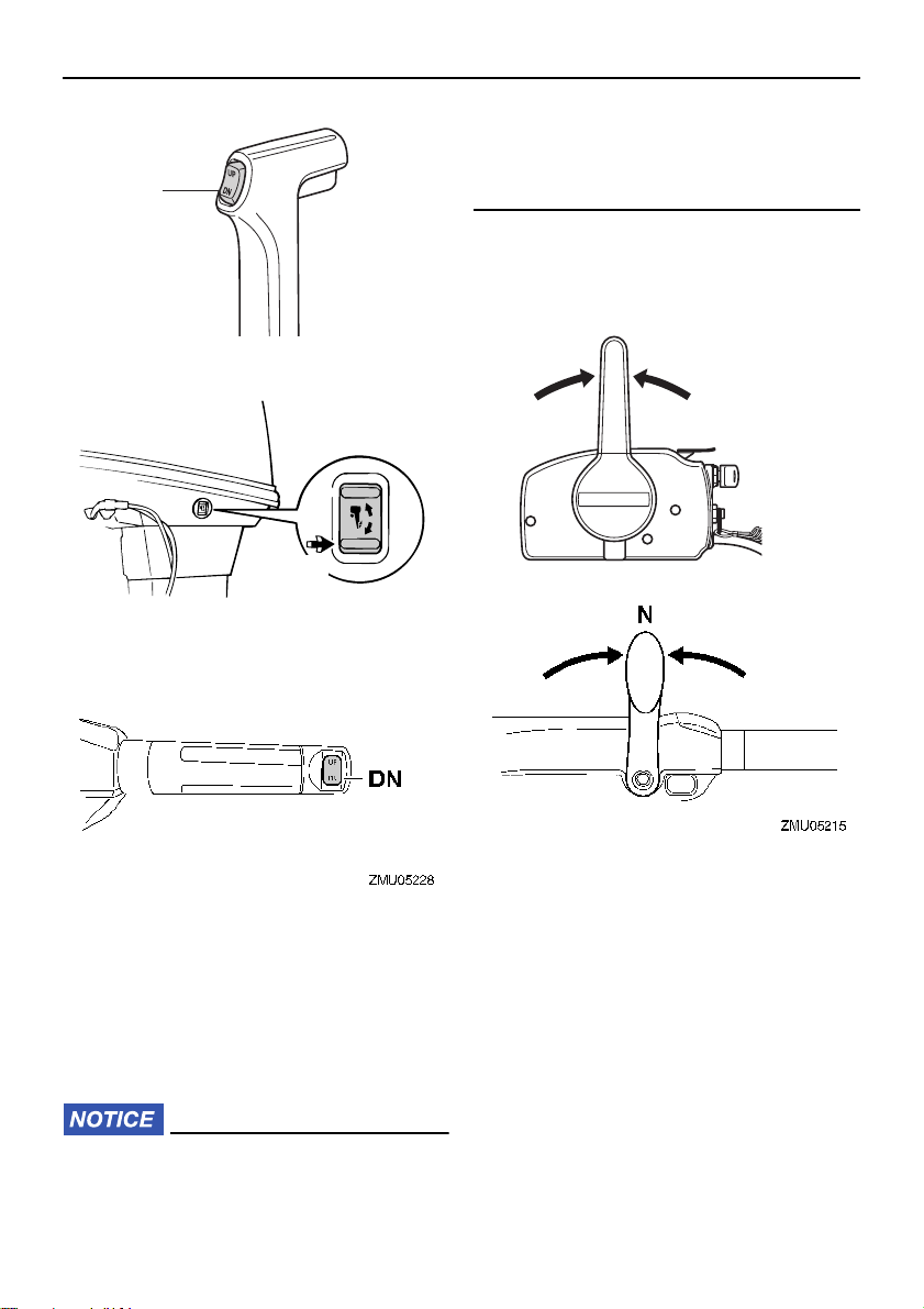
Operation
DN
ZMU01936
DN
ZMU03410
above the surface of the water when setting up for and cruising in shallow water.
Otherwise severe damage from overheating can result.
EMU32914
Procedure for power trim and tilt models
(1) Place the remote control lever / gear
shift lever in neutral.
N
ZMU01771
EMU28063
Shallow water
EMU32852
Power trim and tilt models
The outboard motor can be tilted up partially
to allow operation in shallow water.
ECM00261
Do not tilt the outboard motor up so that
the cooling water inlet on the lower unit is
(2) Slightly tilt the outboard motor up to the
desired position using the power trim
and tilt switch. WARNING! Using the
power trim and tilt switch on the bottom cowling while the boat is moving
or engine is on could increase the
risk of falling overboard and could
distract the operator, increasing the
risk of collision with another boat or
an obstacle.
[EWM01851]
61
Page 68
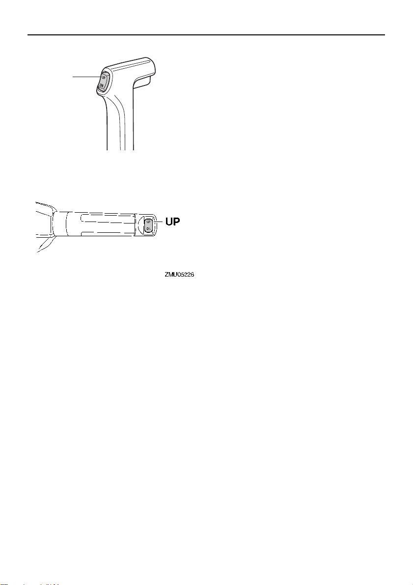
Operation
UP
ZMU01935
(3) To return the outboard motor to the nor-
mal running position, press the power
trim and tilt switch and slowly tilt the outboard motor down.
rosion. Also rinse the outside of the outboard
motor with fresh water.
EMU28196
Cruising in other conditions
Cruising in salt water
After operating in salt water, flush the cooling
water passages with fresh water to prevent
them from becoming clogged. Also rinse the
outside of the outboard motor with fresh water.
Cruising in muddy, turbid, or acidic water
Yamaha strongly recommends that you use
the optional chromium-plated water pump kit
(see page 14) if you use the outboard motor
in acidic water or water with a lot of sediment
in it, such as muddy or turbid (cloudy) water.
After operating in such water, flush the cooling passages with fresh water to prevent cor-
62
Page 69
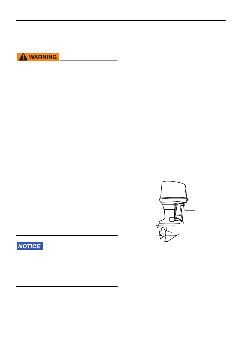
Maintenance
TIP:
ZMU03122
EMU2822B
Transporting and storing
outboard motor
EWM02621
USE CARE when transporting fuel tank,
whether in a boat or car.
DO NOT fill fuel container to maximum
capacity. Gasoline will expand considerably as it warms up and can build up
pressure in the fuel container. This can
cause fuel leakage and a potential fire
hazard.
Leaking fuel is a fire hazard. When
transporting and storing the outboard
motor, disconnect the fuel line from the
outboard motor to prevent fuel from
leaking.
Never get under the outboard motor
while it is tilted. Severe injury could occur if the outboard motor accidentally
falls.
Do not use the tilt support lever or knob
when trailering the boat. The outboard
motor could shake loose from the tilt
support and fall. If the outboard motor
cannot be trailered in the normal running position, use an additional support device to secure it in the tilt
position.
ECM02441
Disconnect the fuel line from the outboard
motor.
Tighten the fuel tank cap and its air vent
screw.
When the outboard motor is tilted pro-
longed time for mooring or trailering the
boat, disconnect the fuel line from the out-
board motor. Tighten the fuel tank cap and
its air vent screw.
The outboard motor should be transported
and stored in the normal running position. If
there is insufficient road clearance in this position, then trailer the outboard motor in the
tilt position using a motor support device
such as a transom saver bar. Consult your
Yamaha dealer for further details.
EMU28237
Clamp screw mounting models
When transporting or storing the outboard
motor while removed from a boat, keep the
outboard motor in the attitude shown.
When storing the outboard motor for prolonged time, fuel must be drained from
the fuel tank. The deteriorated fuel could
clog the fuel line causing engine start difficulty or malfunction.
When storing or transporting the outboard
motor, make sure to follow the procedure listed below.
Place a towel or something similar under the
outboard motor to protect it from damage.
EMU30273
Storing outboard motor
When storing your Yamaha outboard motor
for prolonged periods of time (2 months or
longer), several important procedures must
be performed to prevent excessive damage.
63
Page 70
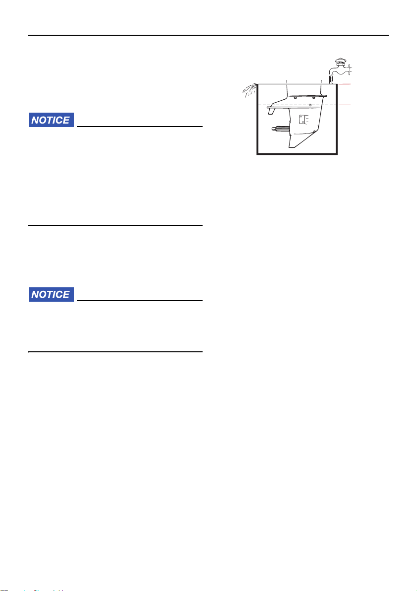
Maintenance
ZMU02051
1
2
It is advisable to have your outboard motor
serviced by an authorized Yamaha dealer
prior to storage. However, you, the owner,
with a minimum of tools, can perform the following procedures.
ECM01412
Do not place the outboard motor on its
side before the cooling water has
drained from it completely, otherwise
water may enter the cylinder through
the exhaust port and cause engine trouble.
Store the outboard motor in a dry, well-
ventilated place, not in direct sunlight.
EMU28306
Procedure
EMU28336
Flushing in a test tank
ECM00302
Before starting the engine, make sure to
supply water to the cooling water passages. Otherwise, the engine could overheat
and be damaged.
(1) Wash the outboard motor body using
fresh water. NOTICE: Do not spray wa-
ter into the air intake.
ther information, see page 65.
(2) Disconnect the fuel line from the motor
or shut off the fuel cock, if equipped.
(3) Remove the engine top cowling and si-
lencer cover. Remove the propeller.
(4) Install the outboard motor on the test tank.
Fill the tank with fresh water to above the
level of the anti-cavitation plate. NOTICE:
If the fresh water level is below the level of the anti-cavitation plate, or if the
water supply is insufficient, engine
seizure may occur.
[ECM01841] For fur-
[ECM00292]
1. Water surface
2. Lowest water level
(5) Cooling system flushing is essential to
prevent the cooling system from clogging up with salt, sand, or dirt. In addition, fogging/lubricating of the engine is
mandatory to prevent excessive engine
damage due to rust. Perform the flushing and fogging at the same time.
WARNING! Do not touch or remove
electrical parts when starting or during operation. Keep hands, hair, and
clothes away from the flywheel and
other rotating parts while the engine
is running.
[EWM00092]
(6) Run the engine at a fast idle for a few
minutes in neutral position.
(7) Just prior to turning off the engine, quick-
ly spray “Fogging Oil” alternately into
each carburetor or the fogging hole of
the silencer cover, if equipped. When
properly done, the engine will smoke excessively and almost stall.
(8) Remove the outboard motor from the
test tank.
(9) Install the silencer cover/cap of fogging
hole and top cowling.
(10)If the “Fogging Oil” is not available, run
the engine at a fast idle until the fuel system becomes empty and the engine
64
Page 71
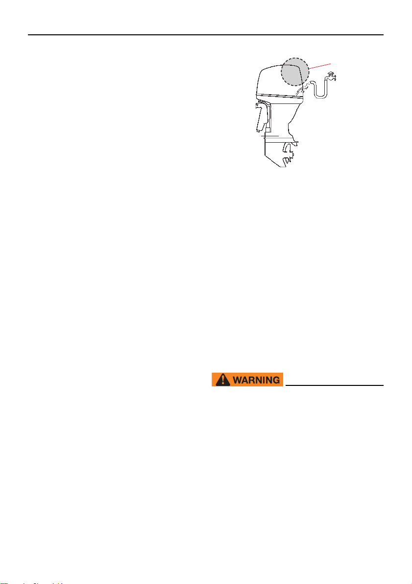
stops.
TIP:
TIP:
(11)Drain the cooling water completely out of
the motor. Clean the body thoroughly.
(12)If the “Fogging Oil” is not available, re-
move the spark plug(s). Pour a teaspoonful of clean engine oil into each
cylinder. Crank several times manually.
Replace the spark plug(s).
(13)Drain the fuel from the fuel tank.
Store the fuel tank in a dry, well-ventilated
place, not in direct sunlight.
Maintenance
1
ZMU07861
1. Air intake
EMU41072
Lubrication
(1) Change the gear oil. For instructions,
see page 75. Check the gear oil for the
presence of water that indicates a leaky
seal. Seal replacement should be performed by an authorized Yamaha dealer
prior to use.
(2) Lubricate all grease fittings. For further
details, see page 70.
For long-term storage, fogging the engine
with fogging oil is recommended. Contact
your Yamaha dealer for information about
fogging oil and procedures for your outboard
motor.
EMU44342
Cleaning the outboard motor
When cleaning the outboard motor, the top
cowling must be installed.
(1) Wash the exterior of the outboard motor
using fresh water. NOTICE: Do not
spray water into the air intake.
[ECM01841]
(2) Drain the cooling water completely out of
the outboard motor. Clean the body thoroughly.
EMU28463
Checking painted surface of
outboard motor
Check the outboard motor for scratches,
nicks, or flaking paint. Areas with damaged
paint are more likely to corrode. If necessary,
clean and paint the areas. Touch-up paint is
available from your Yamaha dealer.
EMU2847G
Periodic maintenance
EWM01872
These procedures require mechanical
skills, tools, and supplies. If you do not
have the proper skills, tools, or supplies
to perform a maintenance procedure,
have a Yamaha dealer or other qualified
mechanic do the work.
The procedures involve disassembling
the motor and exposing dangerous parts.
To reduce the risk of injury from moving,
hot, or electrical parts:
Turn off the engine and keep the key(s)
and engine shut-off cord (lanyard) with
65
Page 72

Maintenance
you when you perform maintenance unless otherwise specified.
The power trim and tilt switches oper-
ate even when the ignition key is off.
Keep people away from the switches
whenever working around the motor.
When the motor is tilted, keep away
from the area under it or between it and
the clamp bracket. Be sure no one is in
this area before operating the power
trim and tilt mechanism.
Allow the engine to cool before han-
dling hot parts or fluids.
Always completely reassemble the mo-
tor before operation.
EMU28512
Replacement parts
If replacement parts are necessary, use only
genuine Yamaha parts or parts of equivalent
design and quality. Any part of inferior quality
may malfunction, and the resulting loss of
control could endanger the operator and
passengers. Yamaha genuine parts and accessories are available from your Yamaha
dealer.
Frequently starting and stopping the en-
gine(s)
Operation that fluctuates often between
light and heavy cargo loads
Outboard motors operating under any of
these above conditions require more frequent maintenance. Yamaha recommends
that you do this service twice as often as
specified in the maintenance chart. For example, if a particular service should be done
at 50 hours, do it instead at 25 hours. This
will help prevent more rapid deterioration of
engine components.
EMU34152
Severe operating conditions
Severe operating conditions involve one or
more of the following types of operation on a
regular basis:
Operating continuously at or near maxi-
mum engine speed (rpm) for many hours
Operating continuously at a low engine
speed (rpm) for many hours
Operating without sufficient time for engine
to warm up and cool down
Frequent quick acceleration and decelera-
tion
Frequent shifting
66
Page 73
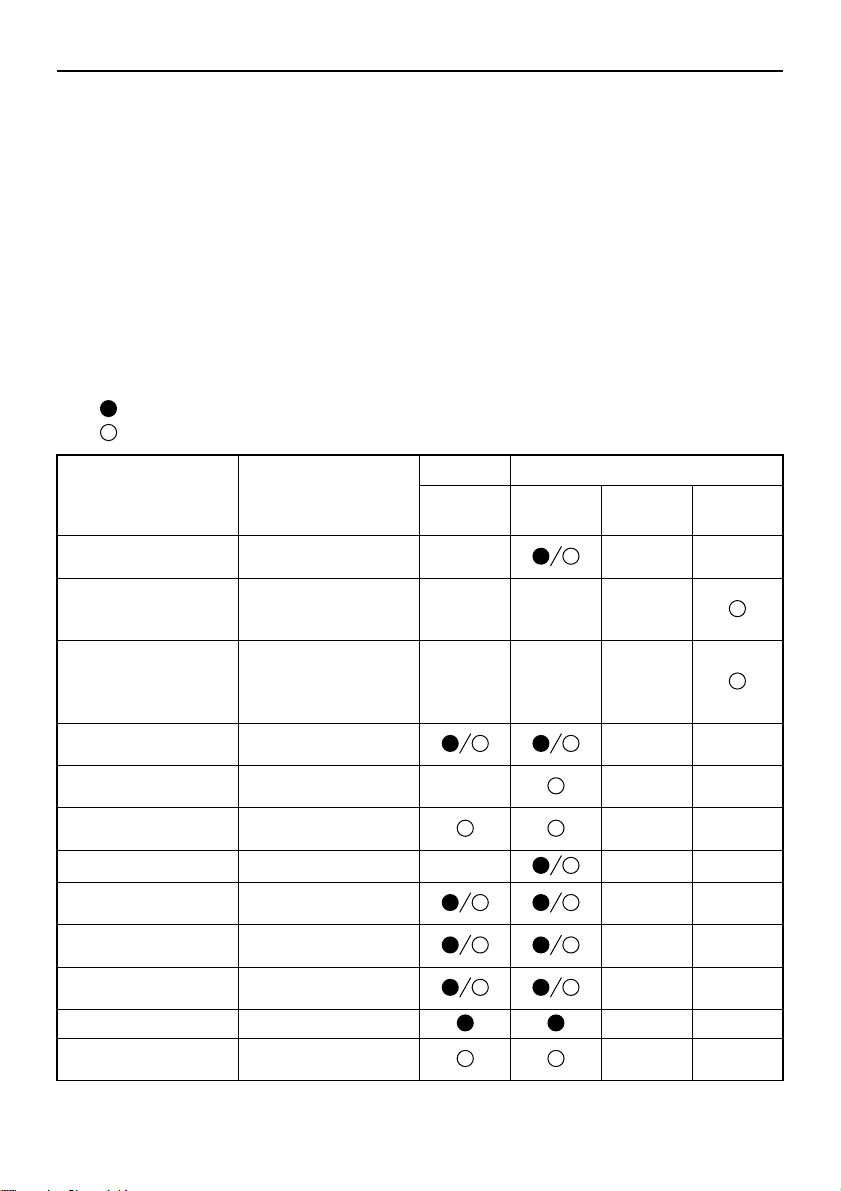
Maintenance
TIP:
EMU34449
Maintenance chart 1
Refer to the sections in this chapter for explanations of each owner-specific action.
The maintenance cycle on these charts assume usage of 100 hours per year and regular
flushing of the cooling water passages. Maintenance frequency should be adjusted when
operating the engine under adverse conditions such as extended trolling.
Disassembly or repairs may be necessary depending on the outcome of maintenance
checks.
Expendable or consumable parts and lubricants will lose their effectiveness over time and
through normal usage regardless of the warranty period.
When operating in salt water, muddy, other turbid (cloudy), acidic water, the engine should
be flushed with clean water after each use.
The “ ” symbol indicates the check-ups which you may carry out yourself.
The “ ” symbol indicates work to be carried out by your Yamaha dealer.
Initial Every
Item Actions
Anode(s) (external)
Anode(s) (cylinder
head, thermostat
cover)
Anodes (exhaust cover,
cooling water passage
cover, Rectifier Regulator cover)
Battery (electrolyte
level, terminal)
Battery (electrolyte
level, terminal)
Cooling water leakage
Cowling lock lever Inspection
Engine starting condition/noise
Engine idle
speed/noise
Fuel filter (can be disassembled)
Fuel line Inspection
Fuel line
Inspection or replacement as necessary
Inspection or replacement as necessary
Replacement
Inspection
Fill, charging or replacing as necessary
Inspection or replacement as necessary
Inspection
Inspection
Inspection or replacement as necessary
Inspection or replacement as necessary
20 hours
(3 months)
100 hours
(1 year)
300 hours
(3 years)
500 hours
(5 years)
67
Page 74
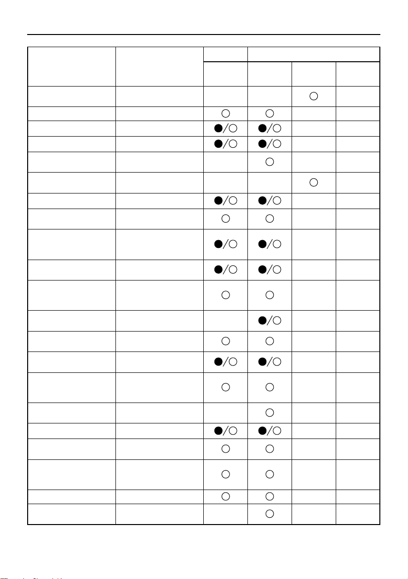
Maintenance
Item Actions
Fuel pump
Fuel/engine oil leakage Inspection
Gear oil Replacement
Greasing points Greasing
Impeller/water pump
housing
Impeller/water pump
housing
Oil tank water drain Inspection or cleaning
Oil injection pump/oil
feed pump
Power trim and tilt
unit/Operation, noise
and oil leakage
Propeller/propeller
nut/cotter pin
Shift link/shift cable
Spark plug(s)
Spark plug caps/spark
plug wires
Water from the cooling
water pilot hole
Throttle link/throttle
cable/throttle pick-up
timing
Thermostat
Cooling water inlet Inspection
Main switch/stop
switch/choke switch
Wire harness connections/wire coupler connections
(Yamaha) Meter/gauge Inspection
Fuel tank (Yamaha portable tank)
Inspection or replacement as necessary
Inspection or replacement as necessary
Replacement
Inspection or Adjustment
Inspection
Inspection or replacement as necessary
Inspection, adjustment
or replacement as necessary
Inspection or replacement as necessary
Inspection or replacement as necessary
Inspection
Inspection, adjustment
or replacement as necessary
Inspection or replacement as necessary
Inspection or replacement as necessary
Inspection or replacement as necessary
Inspection and cleaning as necessary
Initial Every
20 hours
(3 months)
100 hours
(1 year)
300 hours
(3 years)
500 hours
(5 years)
68
Page 75
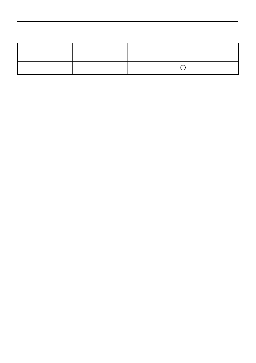
EMU34452
Maintenance chart 2
Maintenance
Item Actions
Exhaust guide/exhaust
manifold
Every
1000 hours
Inspection or replacement as necessary
69
Page 76
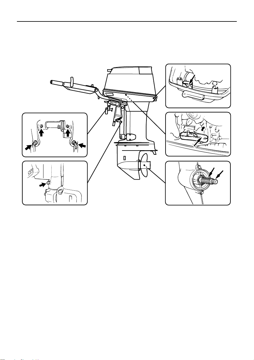
Maintenance
ZMU03415
EMU28945
Greasing
Yamaha grease A (water resistant grease)
Yamaha grease D (corrosion resistant grease; for propeller shaft)
40VMHO
70
Page 77
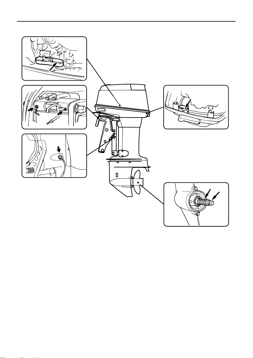
40VEO, 50HETO
ZMU03414
Maintenance
EMU44493
Cleaning and adjusting spark plug
The spark plug is an important engine component and is easy to inspect. The condition
of the spark plug can indicate something
about the condition of the engine. For example, if the center electrode porcelain is very
white, this could indicate an intake air leak or
carburetion problem in that cylinder. Do not
attempt to diagnose any problems yourself.
Instead, take the outboard motor to a
Yamaha dealer. You should periodically re-
move and inspect the spark plug because
heat and deposits will cause the spark plug
to slowly break down and erode.
(1) Remove the spark plug caps from the
spark plugs.
(2) Remove the spark plug. If electrode ero-
sion becomes excessive, or if carbon
and other deposits are excessive, you
should replace the spark plug with another of the correct type. WARNING!
When removing or installing a spark
71
Page 78
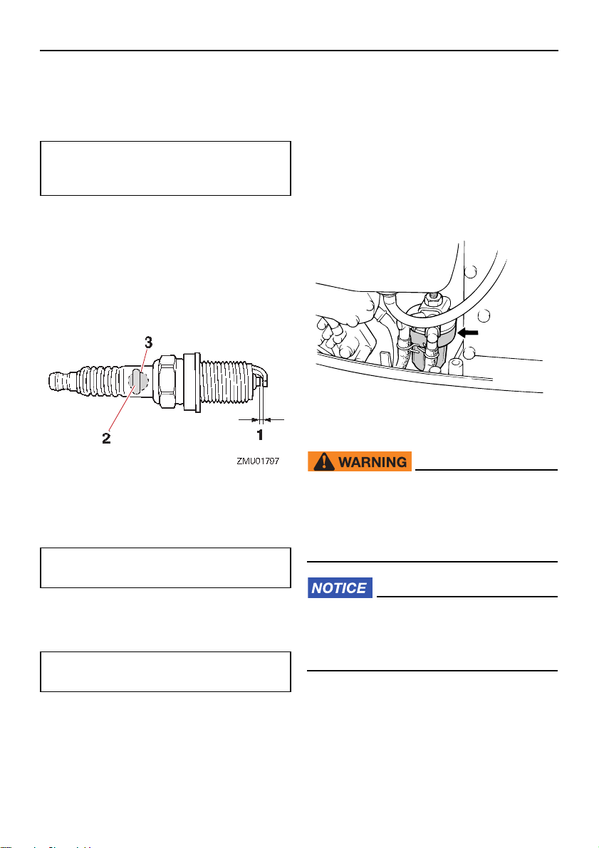
Maintenance
TIP:
11
2
3
1
2
3
ZMU06150
plug, be careful not to damage the insulator. A damaged insulator could
allow external sparks, which could
lead to explosion or fire.
[EWM00562]
Standard spark plug:
BR7HS-10 (40VEO, 40VMHO)
BR8HS-10 (50HETO)
(3) Be sure to use the specified spark plug,
otherwise the engine may not operate
properly. Before fitting the spark plug,
measure the electrode gap with a wire
thickness gauge; replace it if out of specification.
1. Spark plug gap
2. Spark plug part number
3. Spark plug I.D. mark (NGK)
Spark plug gap:
0.9–1.0 mm (0.035–0.039 in)
tight. When you are installing a new spark
plug, a good estimate of the correct torque is
1/2 to 2/3 turn past finger-tight.
EMU37451
Checking fuel filter
Check the fuel filter periodically. If any water
or foreign matter is found in the filter, clean or
replace it. For cleaning or replacement of the
fuel filter, consult your Yamaha dealer.
EMU29045
Inspecting idle speed
EWM00452
Do not touch or remove electrical parts
when starting or during operation.
Keep hands, hair, and clothes away
from the flywheel and other rotating
parts while the engine is running.
ECM00491
(4) When fitting the plug, wipe off any dirt
from the threads, and then screw it in to
the correct torque.
Spark plug torque:
25 N·m (2.5 kgf·m, 18 lb·ft)
If a torque-wrench is not available when you
are reinstalling a spark plug, a good estimate
of the correct torque is 1/12 turn past finger-
72
This procedure must be performed while
the outboard motor is in the water. A
flushing attachment or test tank can be
used.
If the boat is not equipped with a tachometer
for the outboard motor, use a diagnostic tachometer for this procedure. Results may
vary depending on whether testing is conducted with the flushing attachment, in a test
Page 79
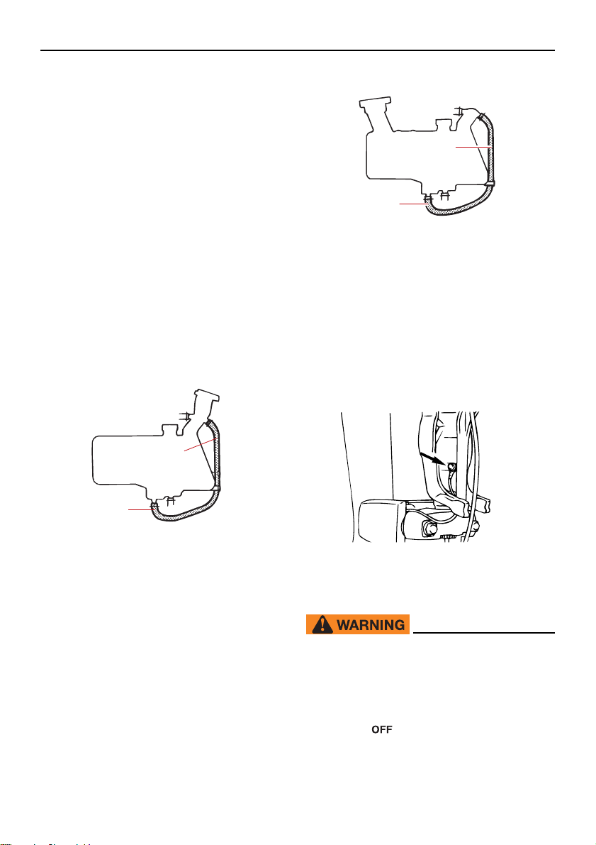
tank, or with the outboard motor in the water.
1
2
ZMU03416
1
2
ZMU04989
ZMU03240
(1) Start the engine and allow it to warm up
fully in neutral until it is running smoothly.
(2) Once the engine has warmed up, verify
whether the idle speed is set to specification. For idle speed specifications, see
page 10. If you have difficulty verifying
the idle speed, or the idle speed requires
adjustment, consult a Yamaha dealer or
other qualified mechanic.
EMU29062
Checking water in engine oil tank
A translucent water drain hose is connected
from the bottom of the oil tank to the filler
neck. If water or foreign matter collects in this
hose, consult a Yamaha dealer.
Maintenance
1. Drain hose
2. Filler neck side
EMU29116
Inspecting wiring and connectors
Inspect that each connector is engaged
securely.
Inspect that each ground lead is properly
secured.
1. Drain hose
2. Filler neck side
EMU32113
Checking propeller
EWM01882
You could be seriously injured if the engine accidentally starts when you are
near the propeller. Before inspecting, removing, or installing the propeller, place
the shift control in neutral, turn the main
switch to “ ” (off) and remove the key,
and remove the clip from the engine shutoff switch. Turn off the battery cut-off
73
Page 80
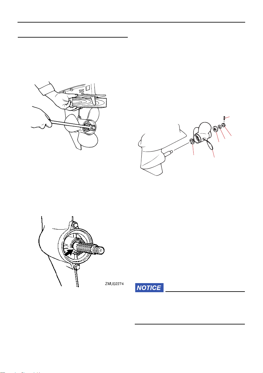
Maintenance
ZMU01897
switch if your boat has one.
Do not use your hand to hold the propeller
when loosening or tightening the propeller
nut. Put a wood block between the anti-cavitation plate and the propeller to prevent the
propeller from turning.
Checkpoints
Check each of the propeller blades for ero-
sion from cavitation or ventilation, or other
damage.
Check the propeller shaft for damage.
Check the splines for wear or damage.
Check for fish line tangled around the pro-
peller shaft.
EMU30663
Removing propeller
EMU29198
Spline models
(1) Straighten the cotter pin and pull it out
using a pair of pliers.
(2) Remove the propeller nut, washer, and
spacer (if equipped). WARNING! Do
not use your hand to hold the propeller when loosening the propeller nut.
[EWM01891]
1
2
3
4
6
1. Cotter pin
2. Propeller nut
3. Washer
4. Spacer
5. Propeller
6. Thrust washer
5
ZMU03131
Check the propeller shaft oil seal for dam-
age.
74
(3) Remove the propeller, washer (if
equipped), and thrust washer.
EMU30673
Installing propeller
EMU46121
Spline models
ECM00502
Make sure to use a new cotter pin and
bend the ends over securely. Otherwise,
the propeller could come off during operation and be lost.
(1) Apply Yamalube Marine Grease or a
corrosion resistant grease to the propel-
Page 81
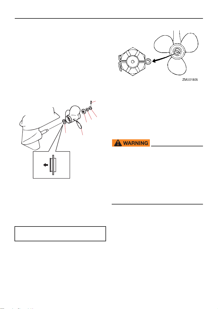
ler shaft.
TIP:
1
2
3
4
5
6
ZMU08159
(2) Install the spacer (if equipped), thrust
washer, washer (if equipped), and propeller on the propeller shaft. NOTICE:
Make sure to install the thrust washer
before installing the propeller. Otherwise, the lower case and propeller
boss could be damaged.
[ECM01882]
(3) Install the spacer (if equipped) and the
washer. Tighten the propeller nut to the
specified torque.
1. Cotter pin
2. Propeller nut
3. Washer
4. Spacer
5. Propeller
6. Thrust washer
Propeller nut tightening torque:
39 N·m (3.9 kgf·m, 29 lb·ft)
(4) Align the propeller nut slot with the pro-
peller shaft hole. Insert a new cotter pin
in the hole and bend the cotter pin ends.
NOTICE: Do not reuse the cotter pin.
Otherwise, the propeller can come off
during operation.
[ECM01892]
Maintenance
If the propeller nut slot does not align with the
propeller shaft hole after tightening the propeller nut to the specified torque, tighten the
nut further to align the slot with the hole.
EMU47070
Changing gear oil
EWM00801
Be sure the outboard motor is securely
fastened to the transom or a stable
stand. You could be severely injured if
the outboard motor falls on you.
Never get under the lower unit while it
is tilted, even when the tilt support lever
or knob is locked. Severe injury could
occur if the outboard motor accidentally falls.
(1) Tilt the outboard motor so that the gear
oil drain screw is at the lowest point possible.
(2) Place a suitable container under the
gear case.
(3) Remove the gear oil drain screw and
gasket. NOTICE: If there is an exces-
sive quantity of metal particles on the
magnetic gear oil drain screw, this
can indicate lower unit problem. Consult your Yamaha dealer.
[ECM01901]
75
Page 82
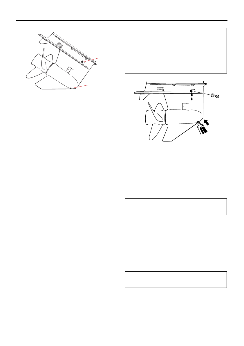
Maintenance
TIP:
TIP:
TIP:
TIP:
2
1
ZMU03133
ZMU03132
1. Gear oil drain screw
2. Oil level plug
If a magnetic gear oil drain screw is
equipped, remove all metal particles from
the screw before installing it.
Always use new gaskets. Do not reuse the
removed gaskets.
(4) Remove the oil level plug and gasket to
allow the oil to drain completely.
NOTICE: Check the used gear oil after
it has been drained. If the gear oil is
milky or contains water or a large
amount of metal particles, the gear
case may be damaged. Have a
Yamaha dealer check and repair the
outboard motor.
For disposal of used oil, consult your
Yamaha dealer.
(5) Put the outboard motor in a vertical posi-
tion. Using a flexible or pressurized filling device, inject the gear oil into the
gear oil drain screw hole.
[ECM00714]
Recommended gear oil:
YAMALUBE outboard gear oil or Hypoid gear oil
Recommended gear oil grade:
SAE 90 API GL-4
Gear oil quantity:
0.430 L (0.455 US qt, 0.378 Imp.qt)
(6) Put a new gasket on the oil level plug.
When the oil begins to flow out of the oil
level plug hole, insert and tighten the oil
level plug.
Apply a light coat of gear oil to the oil level
plug thread and gasket before installation.
Tightening torque:
7 N·m (0.7 kgf·m, 5.2 lb·ft)
(7) Put a new gasket on the gear oil drain
screw. Insert and tighten the gear oil
drain screw.
Apply a light coat of gear oil to the gear oil
drain screw thread and gasket before installation.
Tightening torque:
7 N·m (0.7 kgf·m, 5.2 lb·ft)
76
Page 83
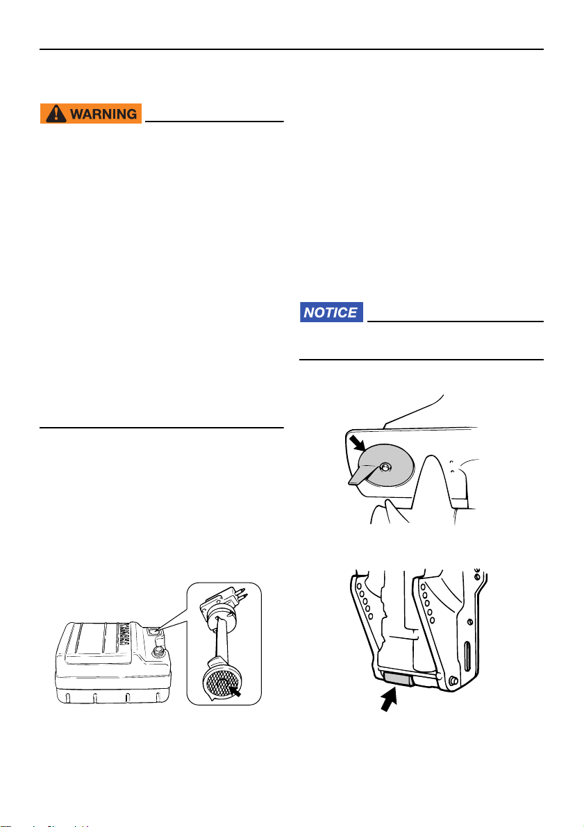
Maintenance
ZMU02324
ZMU03134
ZMU03135
EMU29304
Cleaning fuel tank
EWM00921
Gasoline is highly flammable, and its vapors are flammable and explosive.
If you have any question about properly
doing this procedure, consult your
Yamaha dealer.
Keep away from sparks, cigarettes,
flames, or other sources of ignition
when cleaning the fuel tank.
Remove the fuel tank from the boat be-
fore cleaning it. Work only outdoors in
an area with good ventilation.
Wipe up any spilled fuel immediately.
Reassemble the fuel tank carefully. Im-
proper assembly can result in a fuel
leak, which could result in a fire or ex-
plosion hazard.
Dispose of old gasoline according to lo-
cal regulations.
(1) Empty the fuel tank into an approved
container.
(2) Pour a small amount of suitable solvent
into the tank. Install the cap and shake
the tank. Drain the solvent completely.
(3) Remove the screws holding the fuel joint
assembly. Pull the assembly out of the
tank.
suction pipe) in a suitable cleaning solvent. Allow the filter to dry.
(5) Replace the gasket with a new one. Re-
install the fuel joint assembly and tighten
the screws firmly.
EMU29318
Inspecting and replacing anode(s)
Yamaha outboard motors are protected from
corrosion by sacrificial anodes. Inspect the
external anodes periodically. Remove scales
from the surfaces of the anodes. Consult a
Yamaha dealer for replacement of external
anodes.
ECM00721
Do not paint anodes, as this would render
them ineffective.
(4) Clean the filter (located on the end of the
77
Page 84
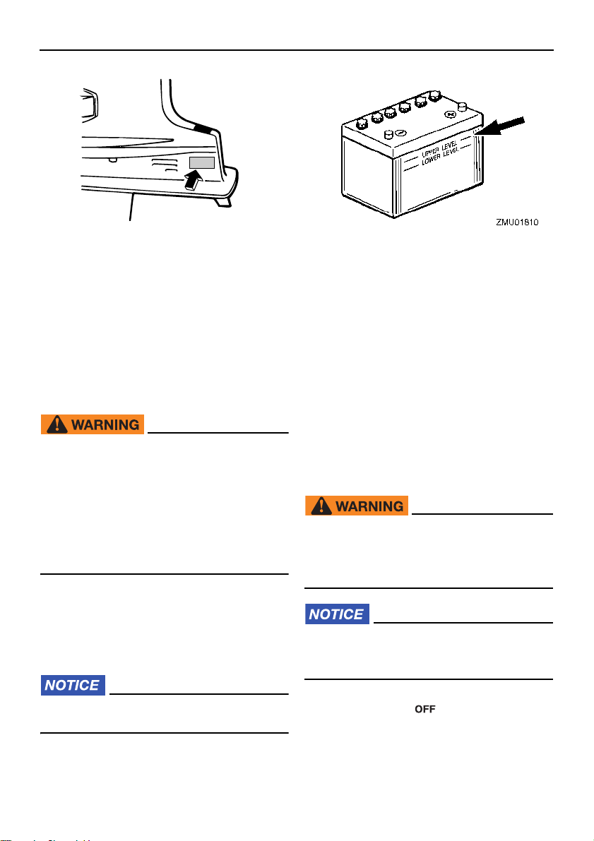
Maintenance
TIP:
ZMU03418
Inspect ground leads attached to external
anodes on equipped models. Consult a
Yamaha dealer for inspection and replacement of internal anodes attached to the power unit.
EMU29324
Checking battery (for electric start
models)
EWM01903
Battery electrolyte is poisonous and
caustic, and batteries generate explosive
hydrogen gas. When working near the
battery:
Wear protective eye gear and rubber
gloves.
Do not smoke or bring any other source
of ignition near the battery.
The procedure for checking the battery varies for different batteries. This procedure
contains typical checks that apply to many
batteries, but you should always refer to the
battery manufacturer’s instructions.
ECM01921
(2) Check the battery’s charge. If your boat
is equipped with the digital speedometer, the voltmeter and low battery alert
functions will help you monitor the battery’s charge. If the battery needs charging, consult your Yamaha dealer.
(3) Check the battery connections. They
should be clean, secure, and covered by
an insulating cover. WARNING! Bad
connections can produce shorting or
arcing and cause an explosion.
[EWM01913]
EMU29335
Connecting the battery
EWM00573
Mount the battery holder securely in a
dry, well-ventilated, vibration-free location in the boat. Install a fully charged battery in the holder.
ECM01125
Do not reverse the battery cables. Otherwise, the electrical parts could be damaged.
A poorly maintained battery will quickly
deteriorate.
(1) Check the electrolyte level.
78
(1) Make sure the main switch (on applica-
ble models) is “ ” (off) before working
on the battery.
(2) Connect the red battery cable to the
POSITIVE (+) terminal first. Then con-
Page 85
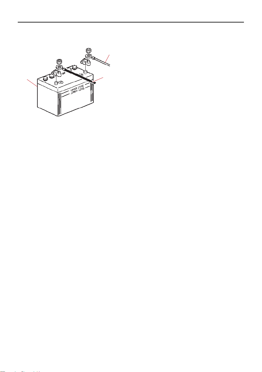
nect the black battery cable to the NEG-
1
2
3
ATIVE (-) terminal.
1. Red cable
2. Black cable
3. Battery
(3) The electrical contacts of the battery and
cables must be clean and properly connected, or the battery will not start the
engine.
EMU29372
Disconnecting the battery
(1) Turn off the battery cut-off switch (if
equipped) and main switch. NOTICE: If
they are left on, the electrical system
can be damaged.
(2) Disconnect the negative cable(s) from
the negative (-) terminal. NOTICE: Al-
ways disconnect all negative (-) cables first to avoid a short circuit and
damage to the electrical system.
[ECM01941]
(3) Disconnect the positive cable(s) and re-
move the battery from the boat.
(4) Clean, maintain, and store the battery
according to the manufacturer’s instructions.
[ECM01931]
Maintenance
79
Page 86

Trouble Recovery
EMU29428
Troubleshooting
A problem in the fuel, compression, or ignition systems can cause poor starting, loss of
power, or other problems. This section describes basic checks and possible remedies,
and covers all Yamaha outboard motors.
Therefore some items may not apply to your
model.
If your outboard motor requires repair, bring
it to your Yamaha dealer.
If the engine trouble-alert indicator is flashing, consult your Yamaha dealer.
Starter will not operate.
Q. Is battery capacity weak or low?
A. Check battery condition. Use battery of
recommended capacity.
Q. Are battery connections loose or corroded?
A. Tighten battery cables and clean battery
terminals.
Q. Is fuse for electric start relay or electric circuit blown?
A. Check for cause of electric overload and
repair. Replace fuse with one of correct amperage.
Q. Are starter components faulty?
A. Have serviced by a Yamaha dealer.
Q. Is shift lever in gear?
A. Shift to neutral.
Engine will not start (starter operates).
Q. Is fuel tank empty?
A. Fill tank with clean, fresh fuel.
Q. Is fuel contaminated or stale?
A. Fill tank with clean, fresh fuel.
Q. Is fuel filter clogged?
A. Clean or replace filter.
Q. Is starting procedure incorrect?
A. See page 47.
Q. Has fuel pump malfunctioned?
A. Have serviced by a Yamaha dealer.
Q. Are spark plug(s) fouled or of incorrect
type?
A. Inspect spark plug(s). Clean or replace
with recommended type.
Q. Are spark plug cap(s) fitted incorrectly?
A. Check and re-fit cap(s).
Q. Is ignition wiring damaged or poorly connected?
A. Check wires for wear or breaks. Tighten
all loose connections. Replace worn or broken wires.
Q. Are ignition parts faulty?
A. Have serviced by a Yamaha dealer.
Q. Is engine shut-off cord (lanyard) not attached?
A. Attach cord.
Q. Are engine inner parts damaged?
A. Have serviced by a Yamaha dealer.
Engine idles irregularly or stalls.
Q. Are spark plug(s) fouled or of incorrect
type?
A. Inspect spark plug(s). Clean or replace
with recommended type.
80
Page 87

Trouble Recovery
Q. Is fuel system obstructed?
A. Check for pinched or kinked fuel line or
other obstructions in fuel system.
Q. Is fuel contaminated or stale?
A. Fill tank with clean, fresh fuel.
Q. Is fuel filter clogged?
A. Clean or replace filter.
Q. Have ignition parts failed?
A. Have serviced by a Yamaha dealer.
Q. Has alert system activated?
A. Find and correct cause of alert.
Q. Is spark plug gap incorrect?
A. Inspect and adjust as specified.
Q. Is ignition wiring damaged or poorly connected?
A. Check wires for wear or breaks. Tighten
all loose connections. Replace worn or broken wires.
Q. Is specified engine oil not being used?
A. Check and replace oil as specified.
A. Return to home position.
Q. Is motor angle too high?
A. Return to normal operating position.
Q. Is carburetor clogged?
A. Have serviced by a Yamaha dealer.
Q. Is fuel joint connection incorrect?
A. Connect correctly.
Q. Is throttle valve adjustment incorrect?
A. Have serviced by a Yamaha dealer.
Q. Is battery cable disconnected?
A. Connect securely.
Alert buzzer sounds or indicator lights.
Q. Is cooling system clogged?
A. Check water intake for restriction.
Q. Is engine oil level low?
A. Fill oil tank with specified engine oil.
Q. Is heat range of spark plug incorrect?
A. Inspect spark plug and replace it with recommended type.
Q. Is thermostat faulty or clogged?
A. Have serviced by a Yamaha dealer.
Q. Are carburetor adjustments incorrect?
A. Have serviced by a Yamaha dealer.
Q. Is fuel pump damaged?
A. Have serviced by a Yamaha dealer.
Q. Is air vent screw on fuel tank closed?
A. Open air vent screw.
Q. Is choke knob pulled out?
Q. Is specified engine oil not being used?
A. Check and replace oil with specified type.
Q. Is engine oil contaminated or deteriorated?
A. Replace oil with fresh, specified type.
Q. Is oil filter clogged?
A. Have serviced by a Yamaha dealer.
Q. Has oil feed/injection pump malfunctioned?
A. Have serviced by a Yamaha dealer.
81
Page 88

Trouble Recovery
Q. Is load on boat improperly distributed?
A. Distribute load to place boat on an even
plane.
Q. Is water pump or thermostat faulty?
A. Have serviced by a Yamaha dealer.
on gear housing?
A. Remove foreign matter and clean lower
unit.
Q. Is fuel system obstructed?
A. Check for pinched or kinked fuel line or
other obstructions in fuel system.
Q. Is there excess water in fuel filter cup?
A. Drain filter cup.
Engine power loss.
Q. Is propeller damaged?
A. Have propeller repaired or replaced.
Q. Is propeller pitch or diameter incorrect?
A. Install correct propeller to operate outboard at its recommended speed (r/min)
range.
Q. Is trim angle incorrect?
A. Adjust trim angle to achieve most efficient
operation.
Q. Is motor mounted at incorrect height on
transom?
A. Have motor adjusted to proper transom
height.
Q. Has alert system activated?
A. Find and correct cause of alert.
Q. Is boat bottom fouled with marine growth?
A. Clean boat bottom.
Q. Is fuel filter clogged?
A. Clean or replace filter.
Q. Is fuel contaminated or stale?
A. Fill tank with clean, fresh fuel.
Q. Is spark plug gap incorrect?
A. Inspect and adjust as specified.
Q. Is ignition wiring damaged or poorly connected?
A. Check wires for wear or breaks. Tighten
all loose connections. Replace worn or broken wires.
Q. Have electrical parts failed?
A. Have serviced by a Yamaha dealer.
Q. Is specified fuel not being used?
A. Replace fuel with specified type.
Q. Is specified engine oil not being used?
A. Check and replace oil with specified type.
Q. Is thermostat faulty or clogged?
A. Have serviced by a Yamaha dealer.
Q. Are spark plug(s) fouled or of incorrect
type?
A. Inspect spark plug(s). Clean or replace
with recommended type.
Q. Are weeds or other foreign matter tangled
82
Q. Is air vent screw closed?
A. Open the air vent screw.
Q. Is fuel pump damaged?
A. Have serviced by a Yamaha dealer.
Page 89
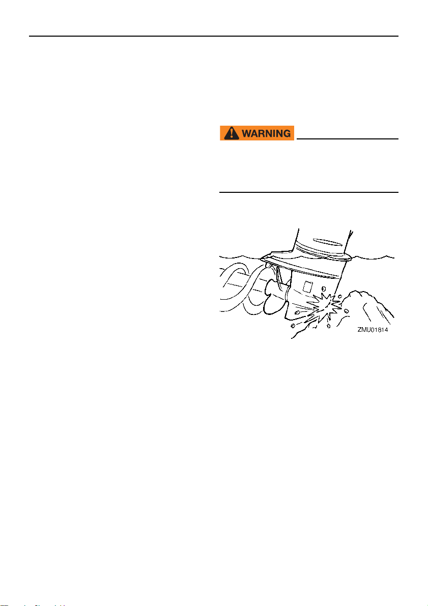
Trouble Recovery
Q. Is fuel joint connection incorrect?
A. Connect correctly.
Q. Is heat range of spark plug incorrect?
A. Inspect spark plug and replace it with recommended type.
Q. Is high pressure fuel pump drive belt broken?
A. Have serviced by a Yamaha dealer.
Q. Is engine not responding properly to shift
lever position?
A. Have serviced by a Yamaha dealer.
Engine vibrates excessively.
Q. Is propeller damaged?
A. Have propeller repaired or replaced.
Q. Is propeller shaft damaged?
A. Have serviced by a Yamaha dealer.
Q. Are weeds or other foreign matter tangled
on propeller?
A. Remove and clean propeller.
Q. Is motor mounting bolt loose?
A. Tighten bolt.
Q. Is steering pivot loose or damaged?
A. Tighten or have serviced by a Yamaha
dealer.
EMU29435
Temporary action in
emergency
EMU29442
Impact damage
EWM00871
The outboard motor can be seriously
damaged by a collision while operating or
trailering. Damage could make the outboard motor unsafe to operate.
If the outboard motor hits an object in t he water, follow the procedure below.
(1) Stop the engine immediately.
(2) Check the control system and all compo-
nents for damage. Also, check the boat
for damage.
(3) Whether damage is found or not, return
to the nearest harbor slowly and carefully.
(4) Have a Yamaha dealer check the out-
board motor before operating it again.
EMU29464
Replacing fuse
If the fuse has blown on an electric start model, open the fuse holder and replace the fuse
with a new one of the proper amperage.
83
Page 90
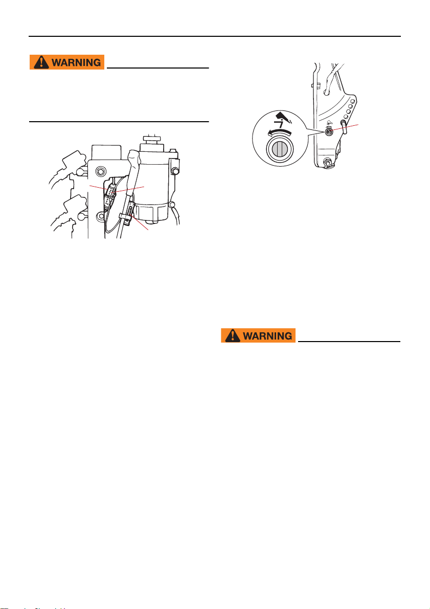
Trouble Recovery
12
3
ZMU03421
EWM00632
Substituting an incorrect fuse or a piece
of wire could allow excessive current
flow. This could cause electric system
damage and a fire hazard.
1
ZMU03422
1. Manual valve screw
(2) Put the engine in the desired position,
then tighten the manual valve screw by
turning it clockwise.
1. Fuse holder
2. Fuse (20 A)
3. Spare fuse (20 A)
Consult your Yamaha dealer if the new fuse
immediately blows again.
EMU29526
Power trim and tilt will not operate
If the engine cannot be tilted up or down with
the power trim and tilt because of a discharged battery or a failure with the power
trim and tilt unit, the engine can be tilted
manually.
(1) Loosen the manual valve screw by turn-
ing it counterclockwise until it stops.
EMU29534
Starter will not operate
If the starter mechanism does not operate
(the engine cannot be cranked with the starter), the engine can be started with an emergency starter rope.
EWM01023
Use this procedure only in an emergen-
cy to return to the nearest port for repairs.
When the emergency starter rope is
used to start the engine, the start-ingear protection device does not operate. Make sure the remote control lever
is in neutral. Otherwise the boat could
unexpectedly start to move, which
could result in an accident.
Attach the engine shut-off cord to a se-
cure place on your clothing, or your
arm or leg while operating the boat.
Do not attach the cord to clothing that
could tear loose. Do not route the cord
where it could become entangled, preventing it from functioning.
84
Page 91
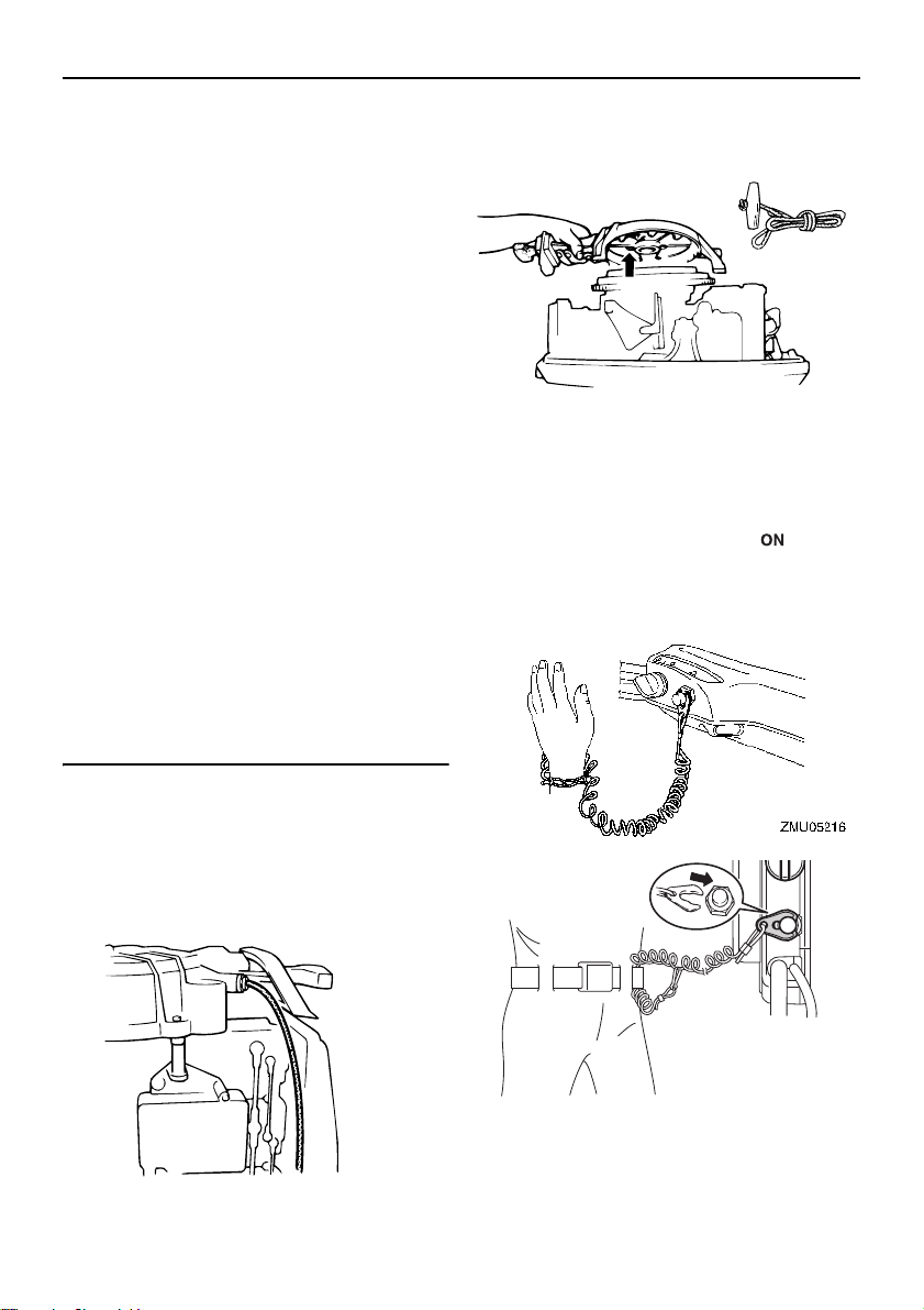
Trouble Recovery
ZMU03425
ZMU03139
ZMU03140
Avoid accidentally pulling the cord dur-
ing normal operation. Loss of engine
power means the loss of most steering
control. Also, without engine power,
the boat could slow rapidly. This could
cause people and objects in the boat to
be thrown forward.
Make sure no one is standing behind
you when pulling the starter rope. It
could whip behind you and injure
someone.
An unguarded, rotating flywheel is very
dangerous. Keep loose clothing and
other objects away when starting the
engine. Use the emergency starter rope
only as instructed. Do not touch the fly-
wheel or other moving parts when the
engine is running. Do not install the
starter mechanism or top cowling after
the engine is running.
Do not touch the ignition coil, spark
plug wire, spark plug cap, or other elec-
trical components when starting or op-
erating the motor. You could get an
electrical shock.
(3) Remove the starter/flywheel cover after
removing the bolt(s).
(4) Prepare the engine for starting. For fur-
ther information, see page 47. Be sure
the engine is in neutral and that the clip
is attached to the engine shut-off switch.
The main switch must be “ ” (on), if
equipped.
EMU29563
Emergency starting engine
(1) Remove the top cowling.
(2) Remove the start-in-gear protection ca-
ble from the starter, if equipped.
85
Page 92
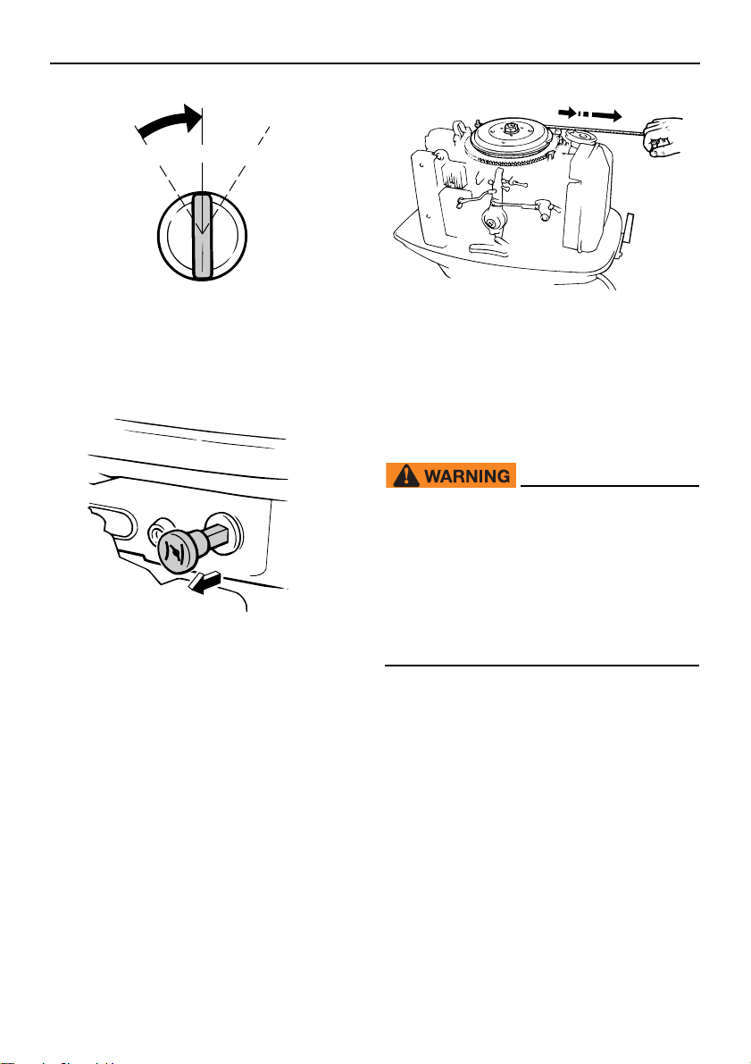
Trouble Recovery
ON STARTOFF
ZMU01906
ZMU03355
ZMU03429
(5) If equipped the choke knob, pull out it
when the engine is cold. After the engine
starts, gradually return the choke knob
to its home position as the engine warms
up.
(6) Insert the knotted end of the emergency
starter rope into the notch in the flywheel
rotor and wind the rope several turns
around the flywheel clockwise.
(7) Give a strong pull straight out to crank
and start the engine. Repeat if necessary.
EMU29672
Engine fails to operate
EMU29707
Cold engine fails to start
If the engine fails to start when it is cold, use
the following procedure.
EWM00411
When starting or operating the engine, do
not touch the ignition coil, spark plug
wire, spark plug cap, or other electrical
parts carrying high voltage. Keep loose
clothing and other objects away from the
engine when starting it. Do not touch the
flywheel or other moving parts when the
engine is running.
(1) Adjust the trim angle so that the drive
shaft is at right angles to the water surface or is trimmed in.
(2) On models equipped with an emergency
starter valve, open it. The valve is located behind the silencer cover on the front
of the engine.
86
Page 93
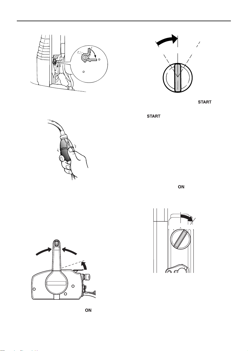
Trouble Recovery
ZMU03141
OPEN
CLOSE
ZMU03142
N
ZMU03143
ON STARTOFF
ZMU03144
(3) Squeeze the primer pump two or three
times to feed fuel.
(4) Open the throttle slightly without shifting
using the throttle grip, neutral throttle lever or free accelerator. It is necessary to
change the throttle opening slightly depending on the engine temperature. After the engine starts, return the throttle to
its original position.
(6) Turn the main switch to “ ” (start).
NOTICE: Never turn the main switch
to “ ” (start) while the engine is
running. Do not keep the starter motor turning for more than 5 seconds. If
the starter motor is turned continuously for more than 5 seconds, the
battery will be quickly discharged,
thus making it impossible to start the
engine. The starter can also be damaged. If the engine will not start after
5 seconds of cranking, return the
main switch to “ ” (on), wait 10 seconds, then crank the engine again.
[ECM00193]
ON
OFF
START
ZMU03335
(5) Turn the main switch to “ ” (on).
(7) After the engine starts, close the emer-
gency starter valve (if used), then return
the throttle to its original position.
87
Page 94
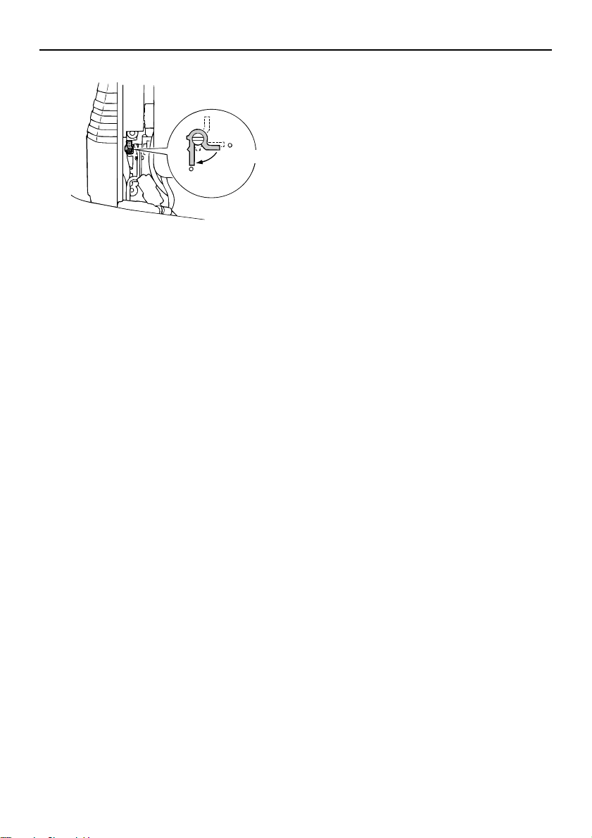
Trouble Recovery
TIP:
ZMU03145
OPEN
CLOSE
When the starter mechanism malfunctions,
see page 84.
EMU33502
Treatment of submerged motor
If the outboard motor is submerged, immediately take it to a Yamaha dealer. Otherwise
some corrosion may begin almost immediately. NOTICE: Do not attempt to run the
outboard motor until it has been completely inspected.
[ECM00402]
88
Page 95

INDEX
A
Alcohol and drugs ................................... 2
Alert indicator........................................ 27
Alert indicator for three indicators ......... 28
Alert system .......................................... 32
Analog tachometer................................ 30
Analog trim meter ................................. 31
Anode(s), inspecting and replacing ...... 77
Anti-fouling paint ................................... 14
Avoid collisions ....................................... 3
B
Battery .................................................. 42
Battery, checking (electric start
models)............................................... 78
Battery, connecting ............................... 78
Battery, disconnecting .......................... 79
Battery requirements ............................ 12
Boat horsepower rating......................... 11
Boating safety ......................................... 2
Boating safety publications ..................... 4
Breaking in engine ................................ 38
C
Carbon monoxide ................................... 2
CE Marking ............................................. 6
Checks after engine warm up ............... 52
Checks after starting engine ................. 51
Checks before starting engine .............. 38
Choke knob........................................... 22
Clamping the outboard motor ............... 36
Cleaning the outboard motor ................ 65
Cold engine fails to start ....................... 86
Collisions with floating or submerged
objects .................................................. 3
Components diagram ........................... 16
Control functions, checking................... 39
Cooling water........................................ 51
Cowling lock lever................................. 26
Cruising in salt water or other
conditions ........................................... 62
D
Digital tachometer................................. 28
E
EC Declaration of Conformity (DoC)....... 5
Electric shock.......................................... 1
Emergency equipment.......................... 15
Emergency starting engine ................... 85
Emergency, temporary action in ........... 83
Engine, checking .................................. 40
Engine fails to operate .......................... 86
Engine oil, checking.............................. 40
Engine oil requirements ........................ 13
Engine oil tank, checking water in ........ 73
Engine shut-off cord (lanyard) .......... 1, 40
Engine shut-off cord (lanyard) and
clip ......................................................21
Engine stop button................................ 22
F
Filling fuel for portable tank................... 42
Filling oil for electric start models.......... 43
Filling oil for manual starter model........ 43
First-time operation............................... 38
Flushing in a test tank........................... 64
Fuel and engine oil, filling .....................42
Fuel filter, checking......................... 39, 72
Fuel leaks, checking for ........................ 39
Fuel level .............................................. 39
Fuel requirements................................. 13
Fuel system .......................................... 39
Fuel tank ............................................... 18
Fuel tank, cleaning................................ 77
Fuse, replacing .....................................83
G
Gasoline............................................ 2, 13
Gasoline exposure and spills.................. 2
Gear oil, changing................................. 75
Gear shift lever ..................................... 20
Greasing ...............................................70
H
Hot parts .................................................1
Hour meter............................................ 29
89
Page 96

INDEX
I
Identification numbers record ................. 5
Idle speed, inspecting ........................... 72
Impact damage ..................................... 83
Installation requirements....................... 11
Instruments and indicators.................... 28
K
Key number ............................................ 5
L
Laws and regulations.............................. 4
Lubrication ............................................ 65
M
Main switch ........................................... 23
Maintenance chart 1 ............................. 67
Maintenance chart 2 ............................. 69
Manual starter handle ........................... 22
Modifications........................................... 2
Mounting height .................................... 35
Mounting outboard motor...................... 11
Mounting the outboard motor................ 35
Muddy or acidic water........................... 14
N
Neutral interlock trigger......................... 20
Neutral throttle lever ............................. 20
O
Oil level alert and oil filter clogging
alert .................................................... 33
Oil level-alert indicator .......................... 28
Oil level indicator (digital type).............. 29
Oil level indicator operation .................. 45
Oil level indicators................................. 30
Operating engine .................................. 46
Operation after long period of
storage ............................................... 40
Outboard motor disposal
requirements ...................................... 14
Outboard motor (painted surface),
checking ............................................. 65
Outboard motor safety ............................ 1
Outboard motor serial number................ 5
Overheat alert ....................................... 32
Overheat-alert indicator ..................28, 30
Overloading ............................................ 3
P
Passengers............................................. 2
Passenger training.................................. 4
People in the water ................................. 2
Periodic maintenance ...........................65
Personal flotation devices (PFDs) .......... 2
Power trim and tilt ................................... 1
Power trim and tilt switch (bottom
cowling) .............................................. 24
Power trim and tilt switch (remote
control or tiller handle) ........................ 24
Power trim and tilt system..................... 41
Power trim and tilt will not operate........ 84
Propeller ................................................. 1
Propeller, checking ...............................73
Propeller, installing ............................... 74
Propeller, removing............................... 74
Propeller selection ................................12
R
Read manuals and labels .......................7
Remote control box............................... 19
Remote control lever............................. 19
Remote control requirements ............... 11
Replacement parts................................ 66
Rotating parts ......................................... 1
S
Sending fuel (portable tank).................. 46
Severe operating conditions .................66
Shallow water ....................................... 61
Shifting.................................................. 52
Shifting (checks after engine warm
up) ...................................................... 52
Spark plug, cleaning and adjusting....... 71
Specifications........................................ 10
Starter will not operate.......................... 84
Start-in-gear protection ......................... 13
Starting engine...................................... 47
90
Page 97

Steering friction adjuster ....................... 23
Stopping boat........................................ 53
Stopping engine.................................... 54
Stop switches........................................ 52
Storing outboard motor ......................... 63
Submerged outboard motor.................. 88
T
Tachometer........................................... 29
Throttle friction adjuster ........................ 21
Throttle grip........................................... 20
Throttle indicator ................................... 21
Tiller handle .......................................... 20
Tilting up and down............................... 58
Tilt lock mechanism .............................. 25
Tilt support lever ................................... 26
Top cowling, installing........................... 41
Top cowling, removing.......................... 39
Transporting and storing outboard
motor .................................................. 63
Trim meter ............................................ 29
Trimming outboard motor ..................... 55
Trim rod (tilt pin).................................... 25
Trim tab with anode .............................. 25
Troubleshooting .................................... 80
INDEX
W
Warming up engine............................... 51
Warning labels ........................................ 7
Weather .................................................. 4
Wiring and connectors, inspecting........ 73
Y
Yamalube.............................................. 13
91
Page 98

Printed in Japan
November 2019–0.1 1 !
 Loading...