

Yamaha 2007 FZ6-N, 2007 FZ6-SA, 2007 FZ6-SHG, 2007 FZ6-SHGW, 2007 FZ6-NAHG Service Manual
...
2007
FZ6-N/S
4S8-28197-E0
SERVICE MANUAL
FZ6-NA/SA
FZ6-NHG(W)
FZ6-SHG(W)
FZ6-NAHG/SAHG

EAS20040
FZ6-N/S
FZ6-NA/SA
FZ6-NHG(W)/SHG(W)
FZ6-NAHG/SAHG
SERVICE MANUAL
©2006 by Yamaha Motor Co., Ltd.
First edition, August 2006
All rights reserved.
Any reproduction or unauthorized use
without the written permission of
Yamaha Motor Co., Ltd.
is expressly prohibited.

EAS20070
NOTICE
This manual was produced by the Yamaha Motor Company, Ltd. primarily for use by Yamaha dealers and their qualified mechanics. It is not possible to include all the knowledge of a mechanic in one
manual. Therefore, anyone who uses this book to perform maintenance and repairs on Yamaha
vehicles should have a basic understanding of mechanics and the techniques to repair these types
of vehicles. Repair and maintenance work attempted by anyone without this knowledge is likely to
render the vehicle unsafe and unfit for use.
This model has been designed and manufactured to perform within certain specifications in regard
to performance and emissions. Proper service with the correct tools is necessary to ensure that the
vehicle will operate as designed. If there is any question about a service procedure, it is imperative
that you contact a Yamaha dealer for any service information changes that apply to this model. This
policy is intended to provide the customer with the most satisfaction from his vehicle and to conform
to federal environmental quality objectives.
Yamaha Motor Company, Ltd. is continually striving to improve all of its models. Modifications and
significant changes in specifications or procedures will be forwarded to all authorized Yamaha dealers and will appear in future editions of this manual where applicable.
NOTE:
• This Service Manual contains information regarding periodic maintenance to the emission control
system. Please read this material carefully.
• Designs and specifications are subject to change without notice.
EAS20080
IMPORTANT MANUAL INFORMATION
Particularly important information is distinguished in this manual by the following.
The Safety Alert Symbol means ATTENTION! BECOME ALERT! YOUR
SAFETY IS INVOLVED!
Failure to follow WARNING instructions could result in severe injury or death
to
the vehicle operator, a bystander or a person checking or repairing the vehicle.
A CAUTION indicates special precautions that must be taken to avoid damage
to the vehicle.
A NOTE provides key information to make procedures easier or clearer.
WARNING
CAUTION:
NOTE:
EAS20090
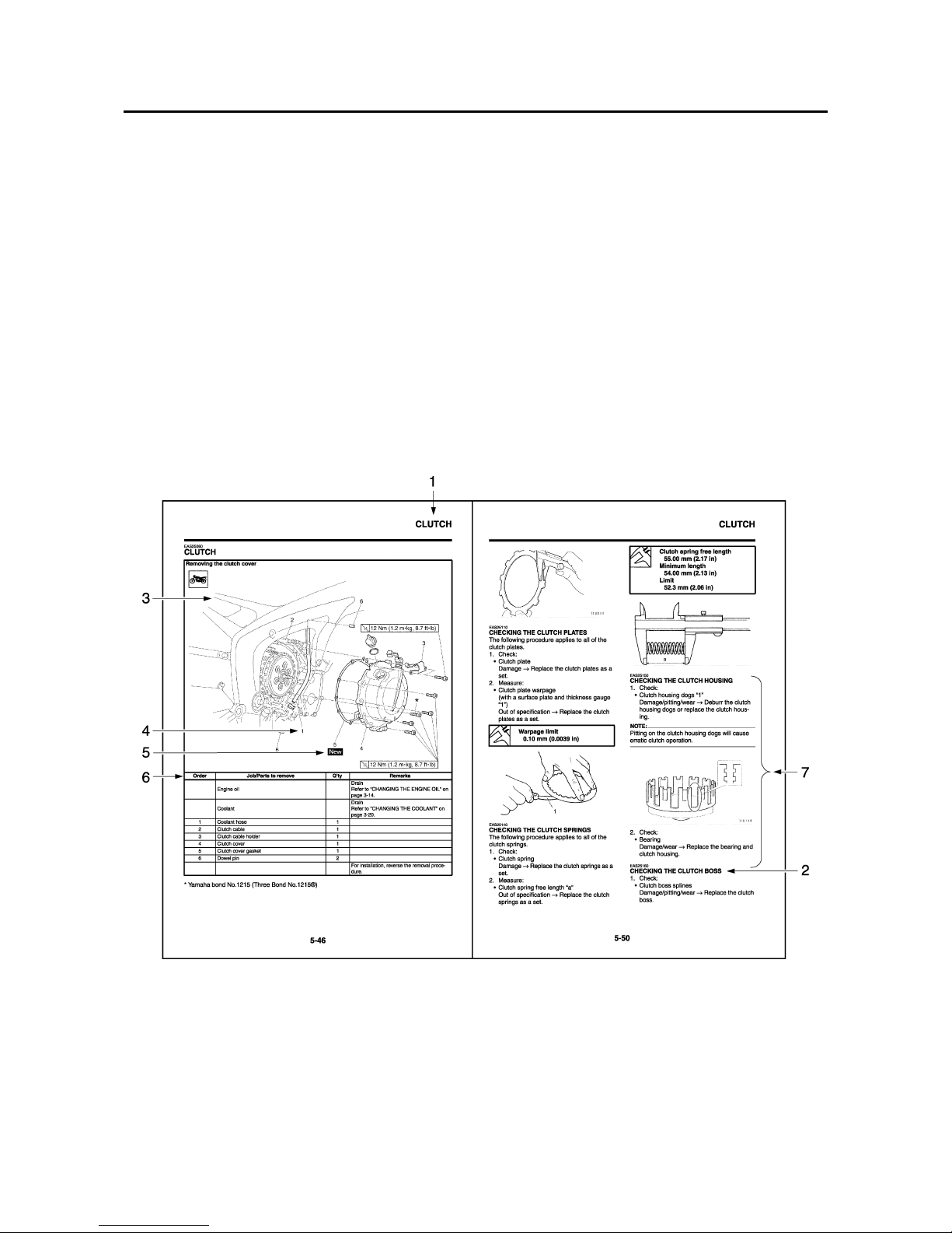
HOW TO USE THIS MANUAL
This manual is intended as a handy, easy-to-read reference book for the mechanic. Comprehensive
explanations of all installation, removal, disassembly, assembly, repair and check procedures are
laid out with the individual steps in sequential order.
• The manual is divided into chapters and each chapter is divided into sections. The current section
title is shown at the top of each page “1”.
• Sub-section titles appear in smaller print than the section title “2”.
• To help identify parts and clarify procedure steps, there are exploded diagrams at the start of each
removal and disassembly section “3”.
• Numbers are given in the order of the jobs in the exploded diagram. A number indicates a disassembly step “4”.
• Symbols indicate parts to be lubricated or replaced “5”.
Refer to “SYMBOLS”.
• A job instruction chart accompanies the exploded diagram, providing the order of jobs, names of
parts, notes in jobs, etc “6”.
• Jobs requiring more information (such as special tools and technical data) are described sequentially “7”.
EAS20100
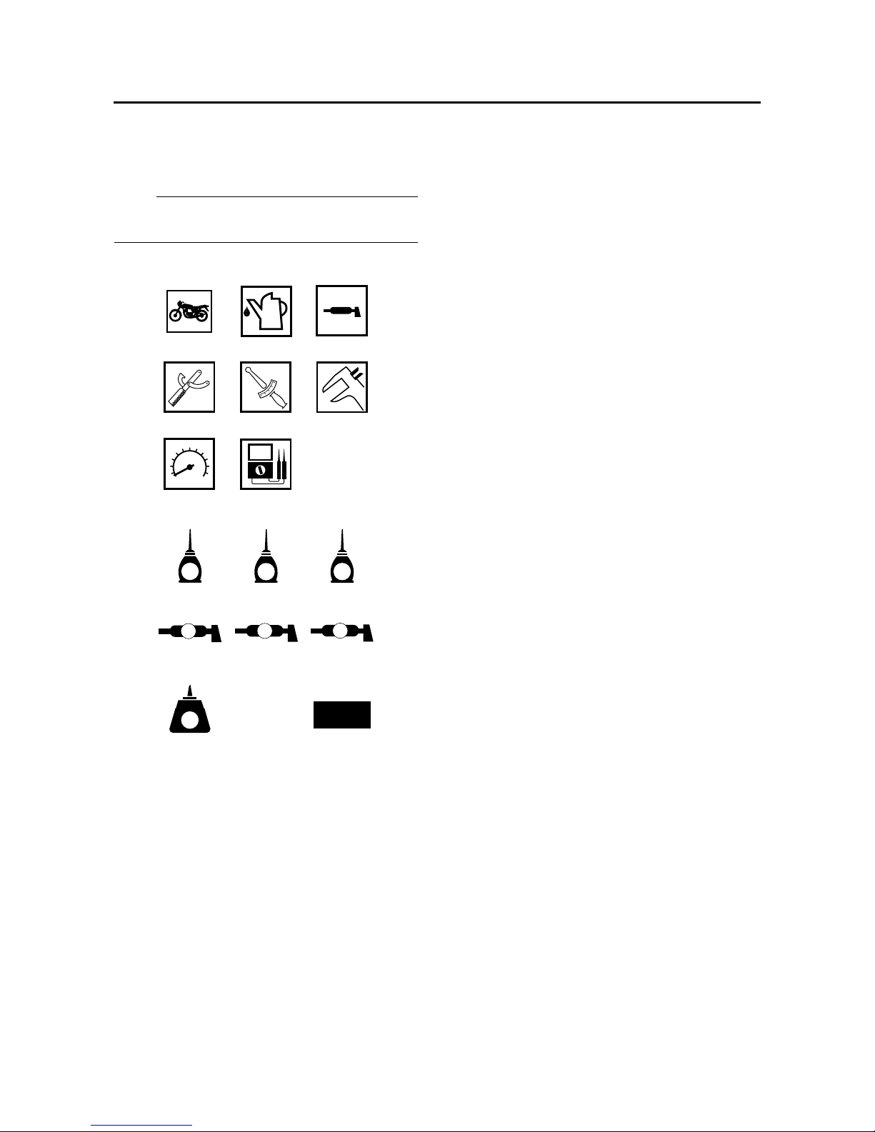
SYMBOLS
The following symbols are used in this manual
for easier understanding.
NOTE:
The following symbols are not relevant to every
vehicle.
1. Serviceable with engine mounted
2. Filling fluid
3. Lubricant
4. Special tool
5. Tightening torque
6. Wear limit, clearance
7. Engine speed
8. Electrical data
9. Engine oil
10.Gear oil
11.Molybdenum-disulfide oil
12.Wheel-bearing grease
13.Lithium-soap-based grease
14.Molybdenum-disulfide grease
15.Apply locking agent (LOCTITE®)
G
M
E
B
LS
M
91011
12 13 14
15 16
LT
New
T
R
.
.
123
456
78
16.Replace the part


1
2
3
4
5
6
7
8
9
EAS20110
TABLE OF CONTENTS
GENERAL INFORMATION
SPECIFICATIONS
PERIODIC CHECKS AND ADJUSTMENTS
CHASSIS
ENGINE
COOLING SYSTEM
FUEL SYSTEM
ELECTRICAL SYSTEM
TROUBLESHOOTING


1
GENERAL INFORMATION
IDENTIFICATION..........................................................................................1-1
VEHICLE IDENTIFICATION NUMBER...................................................1-1
MODEL LABEL.......................................................................................1-1
FEATURES ...................................................................................................1-2
OUTLINE OF FI SYSTEM ......................................................................1-2
FI SYSTEM.............................................................................................1-3
INSTRUMENT FUNCTIONS ..................................................................1-4
OUTLINE OF THE ABS..........................................................................1-9
ABS COMPONENT FUNCTIONS ........................................................1-13
ABS OPERATION.................................................................................1-19
ABS SELF-DIAGNOSIS FUNCTION....................................................1-23
ABS WARNING LIGHT AND OPERATION...........................................1-26
IMPORTANT INFORMATION .....................................................................1-28
PREPARATION FOR REMOVAL AND DISASSEMBLY........................1-28
REPLACEMENT PARTS.......................................................................1-28
GASKETS, OIL SEALS AND O-RINGS................................................1-28
LOCK WASHERS/PLATES AND COTTER PINS.................................1-28
BEARINGS AND OIL SEALS ...............................................................1-29
CIRCLIPS .............................................................................................1-29
CHECKING THE CONNECTIONS .............................................................1-30
SPECIAL TOOLS........................................................................................1-31

IDENTIFICATION
1-1
EAS20130
IDENTIFICATION
EAS20140
VEHICLE IDENTIFICATION NUMBER
The vehicle identification number “1” is
stamped into the right side of the steering
head pipe.
EAS20150
MODEL LABEL
The model label “1” is affixed to the frame. This
information will be needed to order spare
parts.
FEATURES
1-2
EAS20170
FEATURES
EAS4S81003
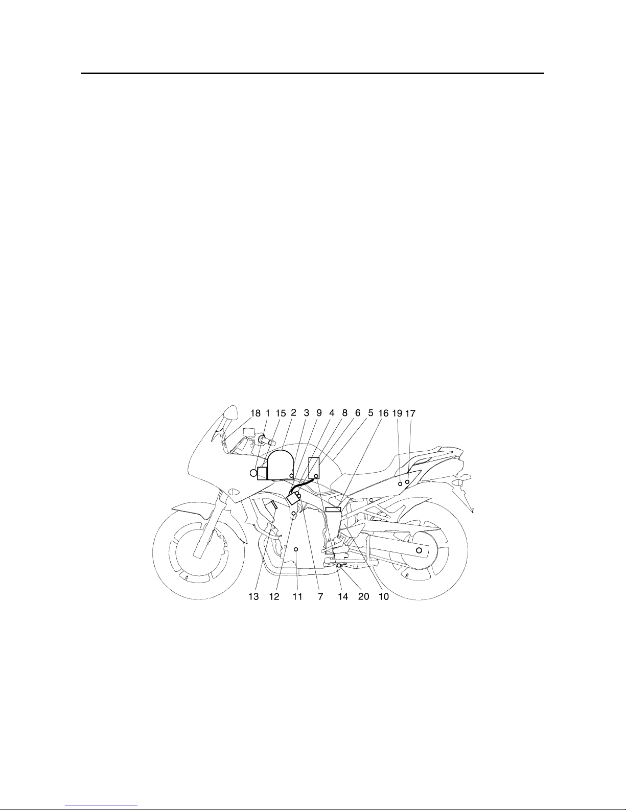
OUTLINE OF FI SYSTEM
The main function of a fuel supply system is to provide fuel to the combustion chamber at the optimum air-fuel ratio in accordance with the engine operating conditions and the atmospheric temperature.
In the conventional carburetor system, the air-fuel ratio of the mixture that is supplied to the combustion chamber is created by the volume of the intake air and the fuel that is metered by the jet used in
the respective carburetor.
Despite the same volume of intake air, the fuel volume requirement varies by the engine operating
conditions, such as acceleration, deceleration, or operating under a heavy load. Carburetors that
meter the fuel through the use of jets have been provided with various auxiliary devices, so that an
optimum air-fuel ratio can be achieved to accommodate the constant changes in the operating conditions of the engine.
As the requirements for the engine to deliver more performance and cleaner exhaust gases
increase, it becomes necessary to control the air-fuel ratio in a more precise and finely tuned manner. To accommodate this need, this model has adopted an electronically controlled fuel injection
(FI) system, in place of the conventional carburetor system. This system can achieve an optimum
air-fuel ratio required by the engine at all times by using a microprocessor that regulates the fuel
injection volume according to the engine operating conditions detected by various sensors.
The adoption of the FI system has resulted in a highly precise fuel supply, improved engine
response, better fuel economy, and reduced exhaust emissions. Furthermore, the air induction system (AI system) has been placed under computer control together with the FI system in order to
realize cleaner exhaust gases.
1. Ignition coil
2. Air filter case
3. Intake air temperature sensor
4. Fuel delivery hose
5. Fuel tank
6. Fuel pump
7. Intake air pressure sensor
8. Throttle position sensor
9. Fuel injector
10.Catalytic converter
11.Crankshaft position sensor
12.Coolant temperature sensor
13.Spark plug
14.Pressure regulator
15.Battery
16.ECU
17.Fuel injection system relay
18.Engine trouble warning light
19.Lean angle sensor
20.O
2
sensor
FEATURES
1-3
EAS4S81004
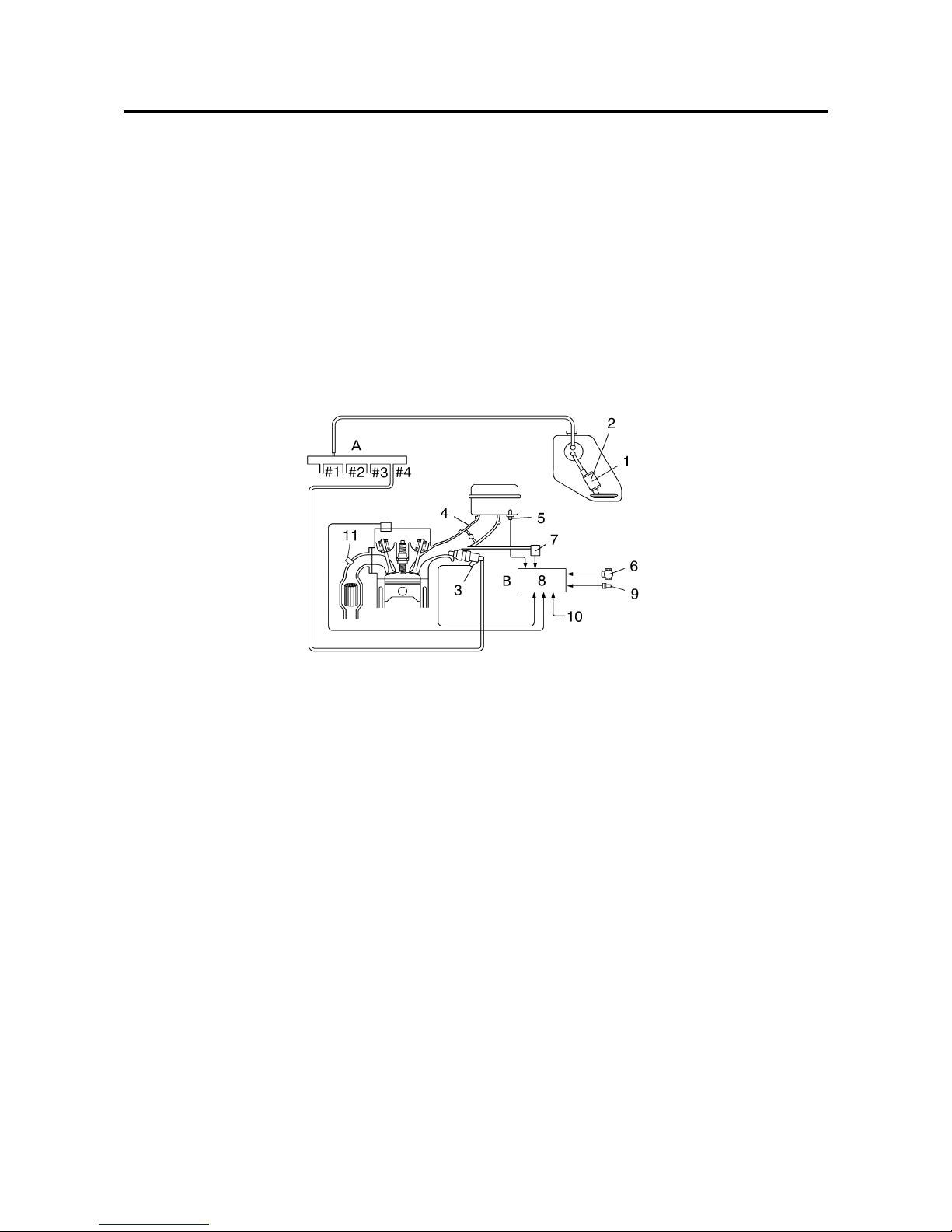
FI SYSTEM
The fuel pump delivers fuel to the injector via the fuel filter. The pressure regulator maintains the fuel
pressure that is applied to the injector at only 250 kPa (2.5 kg/cm
2
). Accordingly, when the energizing signal from the ECU energizes the injector, the fuel passage opens, causing the fuel to be
injected into the intake manifold only during the time the passage remains open. Therefore, the
longer the length of time the injector is energized (injection duration), the greater the volume of fuel
that is supplied. Conversely, the shorter the length of time the injector is energized (injection duration), the lesser the volume of fuel that is supplied.
The injection duration and the injection timing are controlled by the ECU. Signals that are input from
the throttle position sensor, crankshaft position sensor, intake air pressure sensor, intake temperature sensor, coolant temperature sensor and O
2
sensor enable the ECU to determine the injection
duration. The injection timing is determined through the signals from the crankshaft position sensor.
As a result, the volume of fuel that is required by the engine can be supplied at all times in accordance with the driving conditions.
1. Fuel pump
2. Pressure regulator
3. Fuel injector
4. Throttle body
5. Intake air temperature sensor
6. Throttle position sensor
7. Intake air pressure sensor
8. ECU
9. Coolant temperature sensor
10.Crankshaft position sensor
11.O
2
sensor
A. Fuel system
B. Control system
FEATURES
1-4
EAS4S81005
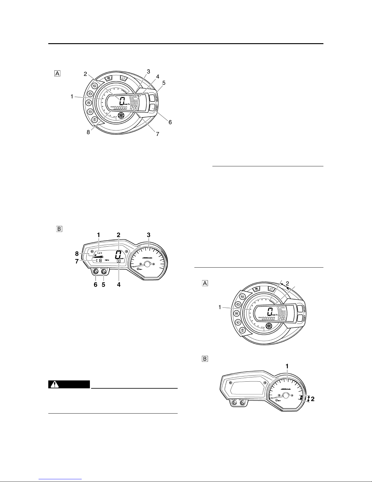
INSTRUMENT FUNCTIONS
Multi-function meter unit
WARNING
EWA4S81002
Be sure to stop the vehicle before making
any setting changes to the multi-function
meter unit.
The multi-function meter unit is equipped with
the following:
• a speedometer (which shows the riding
speed)
• a tachometer (which shows engine speed)
• an odometer (which shows the total distance
traveled)
• two tripmeters (which show the distance traveled since they were last set to zero)
• a fuel reserve tripmeter (which shows the
distance traveled since the left segment of
the fuel meter started flashing)
•a clock
• a fuel meter
• a coolant temperature display
• an air intake temperature display
• a self-diagnosis device
• an LCD and tachometer brightness control
mode
NOTE:
• Be sure to turn the key to “ON” before using
the “SELECT” and “RESET” buttons.
• For the U.K. only: To switch the speedometer
and odometer/tripmeter displays between
kilometers and miles, press the “SELECT”
button for at least two second. (FZ6-N/FZ6NA/FZ6-S/FZ6-SA)
• For the U.K. only: To switch the speedometer
and odometer/tripmeter displays between
kilometers and miles, press the “SELECT”
button for at least one second. (FZ6NHG(W)/FZ6-NAHG/FZ6-SHG(W)/FZ6SAHG)
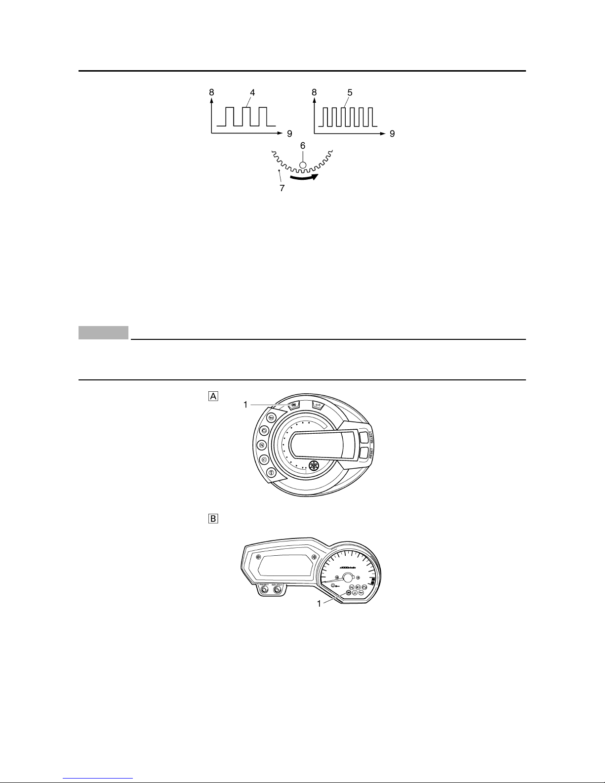
Tachometer
A. FZ6-N/FZ6-NA/FZ6-S/FZ6-SA
1. Tachometer
2. Speedometer
3. Fuel meter
4. Coolant temperature display
5. “SELECT” button
6. “RESET” button
7. Clock/air intake temperature/CO adjusting
mode tachometer display
8. Odometer/tripmeter/fuel reserve tripmeter/
tachometer
B. FZ6-NHG(W)/FZ6-NAHG/FZ6-SHG(W)/
FZ6-SAHG
1. Coolant temperature display/air intake temperature display
2. Speedometer
3. Tachometer
4. Odometer/tripmeter/fuel reserve tripmeter
5. “SELECT” button
6. “RESET” button
7. Clock
8. Fuel meter
A. FZ6-N/FZ6-NA/FZ6-S/FZ6-SA

FEATURES
1-5
The electric tachometer allows the rider to
monitor the engine speed and keep it within
the ideal power range.
When the key is turned to “ON”, the tachometer needle will sweep once across the r/min
range and then return to zero r/min in order to
test the electrical circuit.
CAUTION:
ECA4S81004
Do not operate the engine in the tachometer red zone.
Red zone: 14000 r/min and above
Clock mode
The clock is displayed when the key is turned
to “ON”. In addition, the clock can be displayed
for 10 seconds by pushing the “SELECT” button when the main switch is in the “OFF” or
“LOCK” position.
To set the clock
1 Turn the key to “ON”.
2 Push the “SELECT” button and “RESET” but-
ton together for at least two seconds.
3 When the hour digits start flashing, push the
“RESET” button to set the hours.
4 Push the “SELECT” button, and the minute
digits will start flashing.
5 Push the “RESET” button to set the minutes.
6 Push the “SELECT” button and then release
it to start the clock.
Odometer and tripmeter modes (FZ6-N/FZ6-NA/
FZ6-S/FZ6-SA)
Push the “SELECT” button to switch the display between the odometer mode “ODO” and
the tripmeter modes “TRIP A” and “TRIP B” in
the following order:
“ODO” → “TRIP 1” → “TRIP 2” → “TRIP F” →
“E” → “ODO”
When the fuel amount in the fuel tank
decreases to 3.6 L (0.90 US gal) (0.79
Imp.gal), the bottom segment of the fuel meter
will start flashing, and the odometer display will
automatically change to the fuel reserve tripmeter mode “TRIP F” and start counting the
distance traveled from that point. In that case,
push the “SELECT” button to switch the display between the various tripmeter and odometer modes in the following order:
“TRIP F” → “E” → “ODO” → “TRIP 1” → “TRIP
2” → “TRIP F”
To reset a tripmeter, select it by pushing the
“SELECT” button, and then push the “RESET”
button for at least one second. If you do not
reset the fuel reserve tripmeter manually, it will
reset itself automatically and the display will
return to the prior mode after refueling and
traveling 5 km (3 mi).
B. FZ6-NHG(W)/FZ6-NAHG/FZ6-SHG(W)/
FZ6-SAHG
1. Tachometer
2. Tachometer red zone.
A. FZ6-N/FZ6-NA/FZ6-S/FZ6-SA
B. FZ6-NHG(W)/FZ6-NAHG/FZ6-SHG(W)/
FZ6-SAHG
1. Clock
2. Speedometer
1. Odometer/tripmeter/fuel reserve tripmeter/
tachometer
FEATURES
1-6
Odometer and tripmeter modes (FZ6-NHG(W)/
FZ6-NAHG/FZ6-SHG(W)/FZ6-SAHG)
Push the “SELECT” button to switch the display between the odometer mode “ODO” and
the tripmeter modes “TRIP A” and “TRIP B” in
the following order:
“TRIP A” → “TRIP B” → “ODO” → “TRIP A”
When the fuel amount in the fuel tank
decreases to 3.4 L (0.90 US gal) (0.75
Imp.gal), the left segment of the fuel meter will
start flashing, and the odometer display will
automatically change to the fuel reserve tripmeter mode “F TRIP” and start counting the
distance traveled from that point. In that case,
push the “SELECT” button to switch the display between the various tripmeter and odometer modes in the following order:
“F-TRIP” → “TRIP A” → “TRIP B” → “ODO” →
“F-TRIP”
To reset a tripmeter, select it by pushing the
“SELECT” button, and then push the “RESET”
button for at least one second. If you do not
reset the fuel reserve tripmeter manually, it will
reset itself automatically and the display will
return to the prior mode after refueling and
traveling 5 km (3 mi).
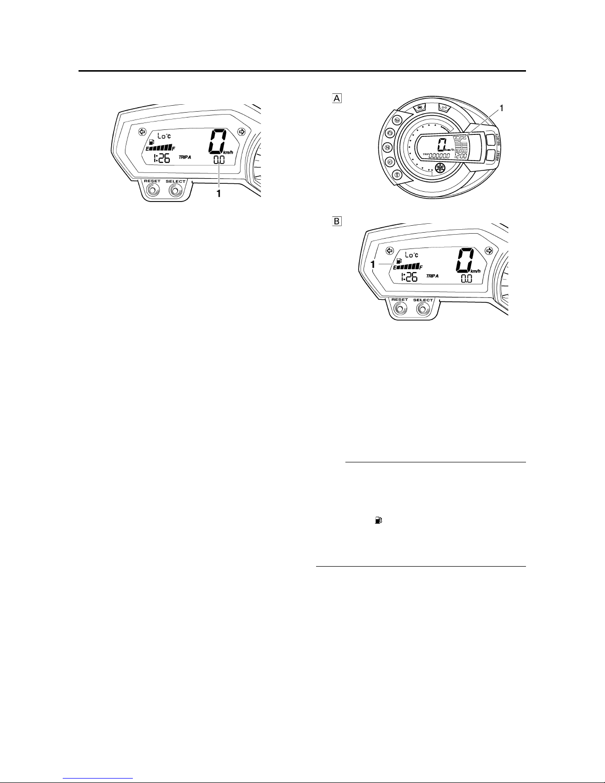
Fuel meter
The fuel meter indicates the amount of fuel in
the fuel tank. The display segments of the fuel
meter disappear towards “E” (Empty) as the
fuel level decreases. When only one segment
is left near “E”, refuel as soon as possible.
NOTE:
This fuel meter is equipped with a self-diagnosis system. If the electrical circuit is defective,
the following cycle will be repeated until the
malfunction is corrected: “E” (Empty), “F” (Full)
and symbol “ ” will flash eight times, then go
off for approximately 3 seconds. If this occurs,
have a Yamaha dealer check the electrical circuit.
1. Odometer/tripmeter/fuel reserve tripmeter
A. FZ6-N/FZ6-NA/FZ6-S/FZ6-SA
B. FZ6-NHG(W)/FZ6-NAHG/FZ6-SHG(W)/
FZ6-SAHG
1. Fuel meter
FEATURES
1-7
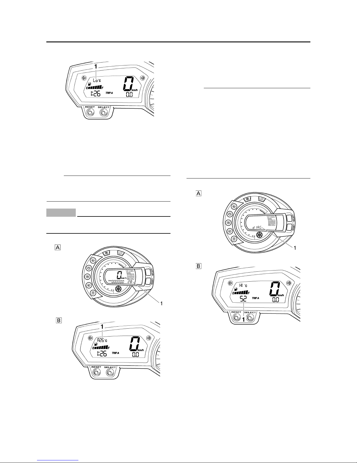
Coolant temperature mode (FZ6-NHG(W)/FZ6NAHG/FZ6-SHG(W)/FZ6-SAHG)
The coolant temperature display indicates the
temperature of the coolant.
Push the “RESET” button to switch the coolant
temperature display to the air intake temperature display.
NOTE:
When the coolant temperature display is
selected, “C” is displayed for one second, and
then the coolant temperature is displayed.
CAUTION:
ECA4S81009
Do not operate the engine if it is overheated.
Air intake temperature mode
The air intake temperature display indicates
the temperature of the air drawn into the air filter case. Push the “RESET” button to switch
the coolant temperature display to the air
intake temperature display.
NOTE:
• Even if the air intake temperature is set to be
displayed, the coolant temperature warning
light comes on when the engine overheats.
• When the key is turned to “ON”, the coolant
temperature is automatically displayed, even
if the air intake temperature was displayed
prior to turning the key to “OFF”.
• When the air intake temperature display is
selected, “A” is displayed for one second,
and then the air intake temperature is displayed. (FZ6-NHG(W)/FZ6-NAHG/FZ6SHG(W)/FZ6-SAHG)
Self-diagnosis device
This model is equipped with a self-diagnosis
device for various electrical circuits.
If any of those circuits are defective, the engine
trouble warning light will come on, and then the
display will indicate a two-digit error code (e.g.,
11, 12, 13).
This model is also equipped with a self-diagnosis device for the immobilizer system.
1. Coolant temperature display
A. FZ6-N/FZ6-NA/FZ6-S/FZ6-SA
B. FZ6-NHG(W)/FZ6-NAHG/FZ6-SHG(W)/
FZ6-SAHG
1. Air intake temperature display
A. FZ6-N/FZ6-NA/FZ6-S/FZ6-SA
B. FZ6-NHG(W)/FZ6-NAHG/FZ6-SHG(W)/
FZ6-SAHG
1. Error code display

FEATURES
1-8
If any of the immobilizer system circuits are
defective, the immobilizer system indicator
light will flash, and then the display will indicate
a two-digit error code (e.g., 51, 52, 53).
NOTE:
If the display indicates error code 52, this could
be caused by transponder interference. If this
error code appears, try the following.
1 Use the code re-registering key to start the
engine.
NOTE:
Make sure there are no other immobilizer keys
close to the main switch, and do not keep more
than one immobilizer key on the same key ring!
Immobilizer system keys may cause signal
interference, which may prevent the engine
from starting
2 If the engine starts, turn it off and try starting
the engine with the standard keys.
3 If one or both of the standard keys do not
start the engine, take the vehicle, the code
re-registering key and both standard keys to
a Yamaha dealer and have the standard keys
re-registered.
If the display indicates any error codes, note
the code number, and then have a Yamaha
dealer check the vehicle.
CAUTION:
ECA4S81010
If the display indicates an error code, the
vehicle should be checked as soon as possible in order to avoid engine damage.
LCD and tachometer brightness control mode
(FZ6-NHG(W)/FZ6-NAHG/FZ6-SHG(W)/FZ6SAHG)
This function allows you to adjust the brightness of the LCD and the tachometer panel and
needle to suit the outside lighting conditions.
To set the brightness
1 Turn the key to “OFF”.
2 Push and hold the “SELECT” button.
3 Turn the key to “ON”, and then release the
“SELECT” button after five seconds.
4 Push the “RESET” button to select the
desired brightness level.
5 Push the “SELECT” button to confirm the
selected brightness level. The display will
return to the odometer or tripmeter mode.
1. Tachometer panel
2. Tachometer needle
3. LCD
4. Brightness level

FEATURES
1-9
EAS4S81007
OUTLINE OF THE ABS
1 The Yamaha ABS (anti-lock brake system) features a dual electronic control system, which acts on
the front and rear brakes independently.
2 The ABS features a compact and lightweight design to help maintain the basic maneuverability of
the vehicle.
3 The hydraulic unit, which is the main component of the ABS, is centrally located on the vehicle to
increase mass centralization.
ABS layout
ABS
The operation of the Yamaha ABS brakes is the same as conventional brakes on other vehicles, with
a brake lever for operating the front brake and a brake pedal for operating the rear brake.
When wheel lock is detected during emergency braking, hydraulic control is performed by the
hydraulic system on the front and rear brakes independently.
Useful terms
• Wheel speed:
The rotation speed of the front and rear wheels.
• Chassis speed:
The speed of the chassis.
When the brakes are applied, wheel speed and chassis speed are reduced. However, the chassis
travels forward by its inertia even though the wheel speed is reduced.
1. ABS warning light
2. ABS ECU (electronic control unit)
3. ABS motor relay
4. Hydraulic unit (HU)
5. Rear brake caliper
6. Rear wheel sensor
7. Rear wheel sensor rotor
8. Front brake caliper
9. Front wheel sensor
10.Front wheel sensor rotor

FEATURES
1-10
•Brake force:
The force applied by braking to reduce the wheel speed.
• Wheel lock:
A condition that occurs when the rotation of one or both of the wheels has stopped, but the vehicle
continues to travel.
• Side force:
The force on the tires which supports the vehicle when cornering.
• Slip ratio:
When the brakes are applied, slipping occurs between the tires and the road surface. This causes
a difference between the wheel speed and the chassis speed. Slip ratio is the value that shows the
rate of wheel slippage and is defined by the following formula.
0%: There is no slipping between the wheel and the road surface. The chassis speed is equal to
the wheel speed.
100%: The wheel speed is “0”, but the chassis is moving (i.e., wheel lock).
Brake force and vehicle stability
When the brake pressure is increased, wheel speed is reduced. Slipping occurs between the tire
and the road surface and brake force is generated. The limit of this brake force is determined by the
friction force between the tire and the road surface and is closely related to wheel slippage. Wheel
slippage is represented by the slip ratio.
Side force is also closely related to wheel slippage. See figure “A”. If the brakes are applied while
keeping the proper slip ratio, it is possible to obtain the maximum brake force without losing much
side force. ABS allows full use of the tires’ capabilities even on slippery road surfaces or less slippery road surfaces. See figure “B”.
Slip ratio =
Chassis speed
– Wheel speed
× 100 (%)
Chassis speed
a. Friction force between the tire and road
surface
b. Brake force
c. Side force
d. Slip ratio (%)
e. Less slippery road surface

FEATURES
1-11
Wheel slip and hydraulic control
The ABS ECU calculates the wheel speed of each wheel according to the rotation signal received
from the front and rear wheel sensors. In addition, the ABS ECU calculates the vehicle chassis
speed and the rate of speed reduction based on the wheel speed values.
The difference between the chassis speed and the wheel speed calculated in the slip ratio formula is
equal to the wheel slip. When the wheel speed is suddenly reduced, the wheel has a tendency to
lock. When the wheel slip and the wheel speed reduction rate exceed the preset values, the ABS
ECU determines that the wheel has a tendency to lock.
If the slip is large and the wheel has a tendency to lock (point A in the following figure), the ABS
ECU reduces the brake fluid pressure in the brake caliper. The ABS ECU increases the pressure of
the brake fluid in the brake caliper when the tendency to lock has diminished (point B in the following
figure).
ABS operation and vehicle control
If the ABS starts operating, there is a tendency of the wheel to lock, and the vehicle is approaching
the limit of control. To make the rider aware of this condition, the ABS has been designed to generate a reaction-force pulsating action in the brake lever and brake pedal independently.
NOTE:
When the ABS is activated, a pulsating action may be felt at the brake lever or brake pedal, but this
does not indicate a malfunction.
The higher the side force on a tire, the less traction there is available for braking. This is true
whether the vehicle is equipped with ABS or not. Therefore, sudden braking while cornering is not
recommended. Excessive side force, which ABS cannot prevent, could cause the tire to slip sideways.
f. Controlling zone
g. Slippery road surface
a. Vehicle speed
b. Wheel speed
c. Pressurized
d. Depressurized
e. Brake force

FEATURES
1-12
WARNING
EWA4S81004
The braking of the vehicle, even in the worst case, is principally executed when the vehicle is
advancing straight ahead. During a turn, sudden braking is liable to cause a loss of traction
of the tires. Even in vehicles equipped with ABS, overturning of the vehicle cannot be prevented if it is braked suddenly.
The ABS functions to prevent the tendency of the wheel to lock by controlling the brake fluid pressure. However, if there is a tendency of the wheel to lock on a slippery road surface, due to engine
braking, the ABS may not be able to prevent the wheel from locking.
WARNING
EWA13870
The ABS controls only the tendency of the wheel to lock caused by applying the brakes. The
ABS cannot prevent wheel lock on slippery surfaces, such as ice, when it is caused by
engine braking, even if the ABS is operating.
Electronic ABS features
The Yamaha ABS (anti-lock brake system) has been developed with the most advanced electronic
technology.
The ABS control is processed with good response under various vehicle travel conditions.
The ABS also includes a highly developed self-diagnosis function. The ABS detects any problem
condition and allows normal braking even if the ABS is not operating properly.
When this occurs, the ABS warning light on the meter assembly comes on.
The ABS stores the malfunction codes in the memory of the ABS ECU for easy problem identification and troubleshooting.
a. Friction force between the tire and road
surface
b. Brake force
c. Side force
d. Slip ratio (%)
FEATURES
1-13
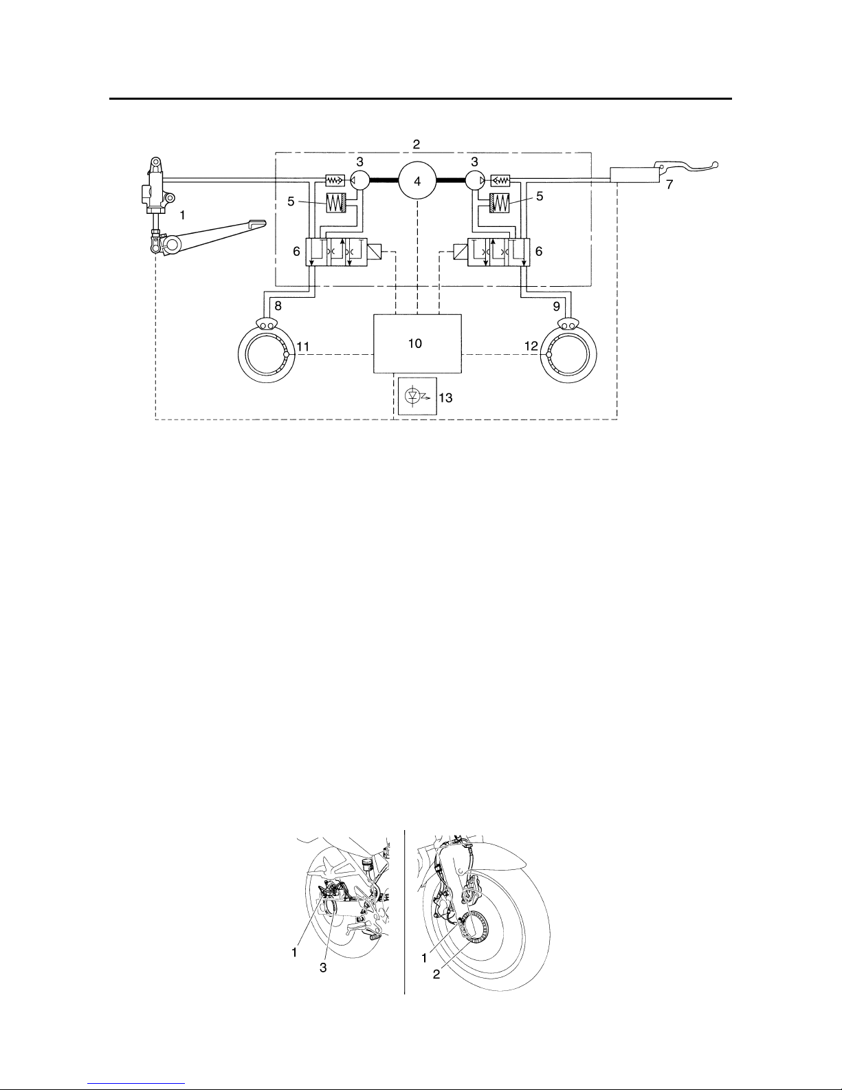
ABS block diagram
EAS4S81008
ABS COMPONENT FUNCTIONS
Wheel sensors and wheel sensor rotors
Wheel sensors “1” detect the wheel rotation speed and transmit the wheel rotation signal to the ABS
ECU.
Each wheel sensor is composed of a permanent magnet and a hall IC. The wheel sensors are
installed in the sensor housing for each wheel.
Sensor rotor “2” is pressed in the inner side of the front wheel hub and rotate with the wheel.
Sensor rotor “3” is install on the rear hub and rotate with the wheel. The sensor rotors have 42/front,
44/rear serrations inside and are installed close to the wheel sensors. As the sensor rotor rotates,
the hall element in the hall IC installed in the wheel sensor generates the voltage which is proportional to the magnetic flux density, and the generated voltage is processed for waveform shaping in
the hall IC to output.
The ABS ECU calculates the wheel rotation speed by detecting the frequency of this voltage.
1. Rear brake master cylinder
2. Hydraulic unit
3. Hydraulic pump
4. ABS motor
5. Buffer chamber
6. Hydraulic control valve
7. Front brake master cylinder
8. Rear brake caliper
9. Front brake caliper
10.ABS ECU
11.Rear wheel sensor
12.Front wheel sensor
13.ABS warning light
FEATURES
1-14
ABS warning light
The ABS warning light “1” comes on to warn the rider if a malfunction in the ABS occurs.
When the main switch is turned to “ON”, the ABS warning light comes on for 2 seconds, then goes
off, so that the rider can check if the ABS warning light is disconnected and check if the ABS is operating properly.
CAUTION:
ECA4S81005
If the rear wheel is raced with the vehicle on the suitable stand, the ABS warning light may
flash or come on. If this occurs, turn the main switch to “OFF”, then back to “ON”. The ABS
operation is normal if the ABS warning light comes on for 2 seconds, then goes off.
4. At low speed
5. At high speed
6. Wheel sensor
7. Wheel sensor rotor
8. Voltage
9. Time
A. FZ6-NA/FZ6-SA
B. FZ6-NAHG/FZ6-SAHG

FEATURES
1-15
Hydraulic unit
The hydraulic unit “1” is composed of three hydraulic control valves (each with a solenoid valve and
flow control valve), two buffer chambers, two hydraulic pumps, and an ABS motor. The hydraulic unit
adjusts the front and rear wheel brake fluid pressure to control the wheel speed according to signals
transmitted from the ABS ECU.
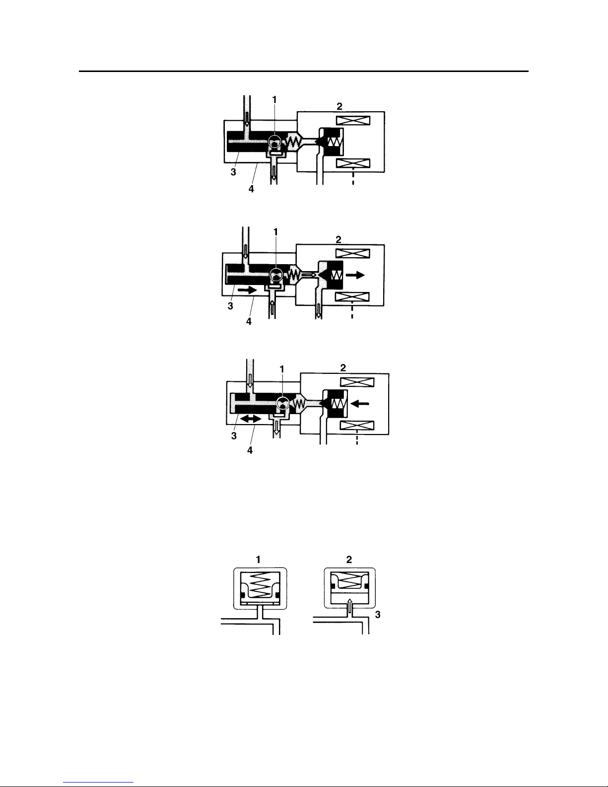
• Hydraulic control valve
The hydraulic control valve is composed of a flow control valve and solenoid valve.
When the ABS is activated, the flow control valve regulates the flow of brake fluid to the brake and
the solenoid valve decreases and increases the brake fluid pressure.
1.When the brakes are operated normally, the solenoid valve “2” is closed, the spool “3” of the flow
control valve does not move, and the hydraulic line between the brake master cylinder and brake
caliper is open.
2.When the ABS is activated, the solenoid valve “2” is opened by the power supplied from the ABS
ECU signals to decrease the brake fluid pressure and the spool “3” of the flow control valve is
moved toward the solenoid valve.
3.When the ABS ECU stops transmitting signals to decrease the brake fluid pressure, the solenoid
valve “2” closes and the brake fluid is pressurized again. Pressurizing the brake fluid again, while
the ABS is activated, limits the flow of the brake fluid with the movement of the flow control valve
spool “3” and provides a gradual pressure increase.
1. To the rear brake master cylinder
2. Hydraulic pump
3. ABS motor
4. Buffer chamber
5. Hydraulic control valve
6. To the front brake master cylinder
7. To the rear brake caliper
8. To the ABS ECU
9. To the front brake caliper
FEATURES
1-16
• Buffer chamber
The buffer chamber accumulates the brake fluid that is depressurized while the ABS is operating.
1. Orifice
2. Solenoid valve
3. Spool
4. Flow control valve
1. Buffer chamber (pressurized)
2. Buffer chamber (depressurized)
3. Raised piston
FEATURES
1-17
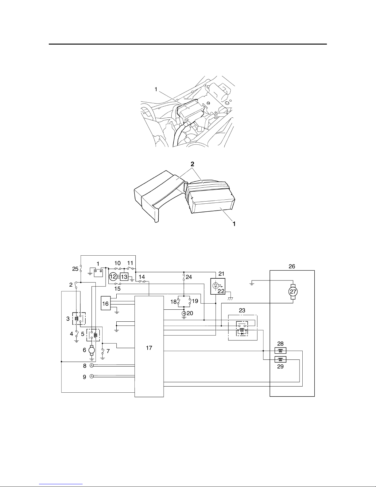
ABS ECU (electronic control unit)
The ABS ECU “1” controls the ABS and is installed under the fuel tank. To protect the ABS ECU
from water damage, it is protected by a cover “2”.
As shown in the block following diagram, the ABS ECU receives wheel sensor signals from the front
and rear wheels and also receives signals from other monitor circuits.
1. Battery
2. Engine stop switch
3. Starting circuit cut-off relay
4. Sidestand switch
5. Starter relay
6. Starter motor
7. Start switch
8. Front wheel sensor
9. Rear wheel sensor
10.Main fuse
11.Main switch
12.Generator

FEATURES
1-18
The necessary actions are confirmed using the monitor circuit and control signals are transmitted to
the hydraulic unit and ABS motor relay.
ABS control operation
The ABS control operation performed in the ABS ECU is divided into the following two parts.
• Hydraulic control
• Self-diagnosis
These operations are performed once every 8/1000th of a second. When a failure is detected in the
ABS, a malfunction code is stored in the memory of the ABS ECU for easy problem identification
and troubleshooting.
NOTE:
Some types of failures are not recorded in the memory of the ABS ECU (e.g., a drop in battery voltage).
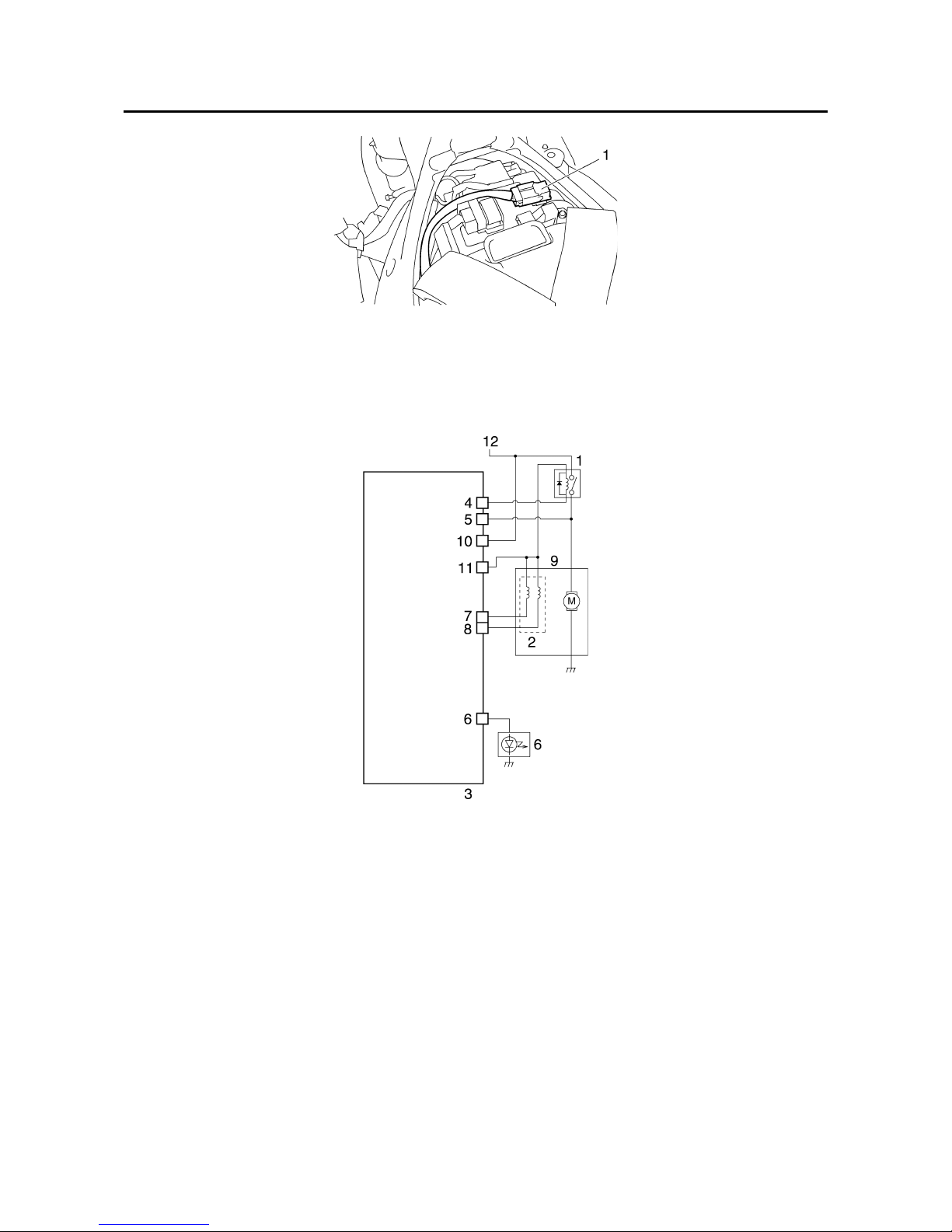
ABS motor relay
The ABS motor relay “1” controls the power supply of the hydraulic unit and is located on the battery.
13.Rectifier/regulator
14.ABS fuse
15.ABS motor fuse
16.ABS test coupler
17.ABS ECU
18.Rear brake light switch
19.Front brake light switch
20.Tail/brake light
21.Meter assembly
22.ABS warning light
23.ABS motor relay
24.Signal fuse
25.Ignition fuse
26.Hydraulic unit
27.ABS motor
28.Front brake solenoid
29.Rear brake solenoid
1. Software operation flow
2. Main switch “ON”
3. Initialize
4. Self-diagnosis (when static)
5. Self-diagnosis (when riding)
6. Receive signals
7. Control operation
8. Depressurize/pressurize
A. 8/1000th of a second
FEATURES
1-19
Composition and operation
The ABS motor relay is activated by signals transmitted from the ABS ECU and operates simultaneously when the ABS starts to reduce the hydraulic pressure of the brake fluid. If the solenoid relay
is turned off, the ABS motor relay is also deactivated and the motor stops operating if there is a malfunction.
EAS4S81009
ABS OPERATION
The ABS hydraulic circuit consists of two systems: the front wheel, and rear wheel. The following
describes the front system only.
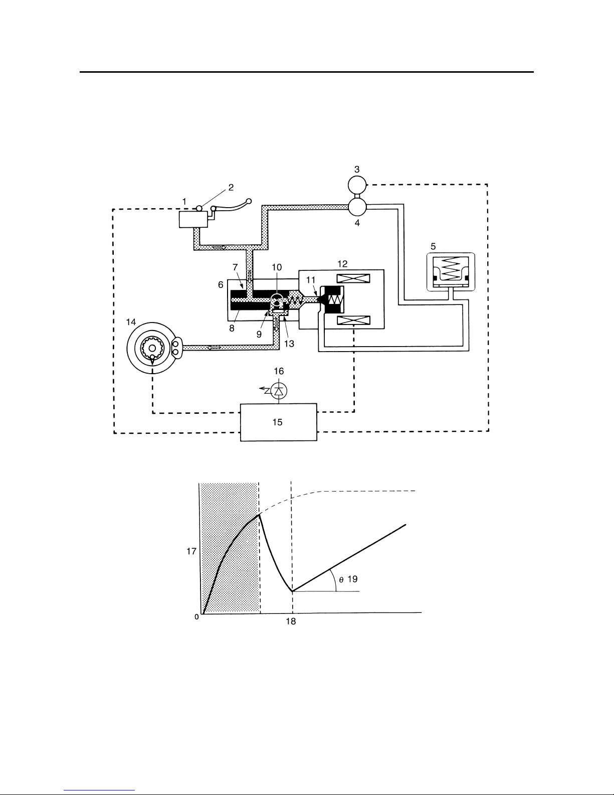
Normal braking (ABS not activated)
When the ABS is not activated, port D “11” of the solenoid valve is closed because a control signal
has not been transmitted from the ABS ECU and port A “7” and port B “9” of the flow control valve
are open.
1. ABS motor relay
2. Solenoid valves
3. ABS ECU
4. Pump motor relay coil
5. Pump motor monitor
6. ABS warning light
7. Front brake solenoid
8. Rear brake solenoid
9. Hydraulic unit
10.Power supply
11.Power of solenoid
12.Power
FEATURES
1-20
Therefore, when the brake lever is squeezed, the hydraulic pressure in the brake master cylinder
increases and the brake fluid is sent to the brake caliper via port A “7” and port B “9”.
At this time, the inlet and outlet check valves of the pump close the lines and brake fluid is not sent.
As a result, the brake master cylinder directly pressurizes the brake caliper during normal braking.
When the brake lever is released, the brake fluid in the brake caliper returns to the brake master cylinder via port A “7” and port B “9”.
1. Brake master cylinder
2. Brake light switch
3. ABS motor
4. Hydraulic pump
5. Buffer chamber
6. Flow control valve
7. Port A
8. Spool
9. Port B
10.Orifice
11.Port D
12.Solenoid valve
13.Port C
14.Brake caliper
15.ABS ECU
16.ABS warning light
FEATURES
1-21
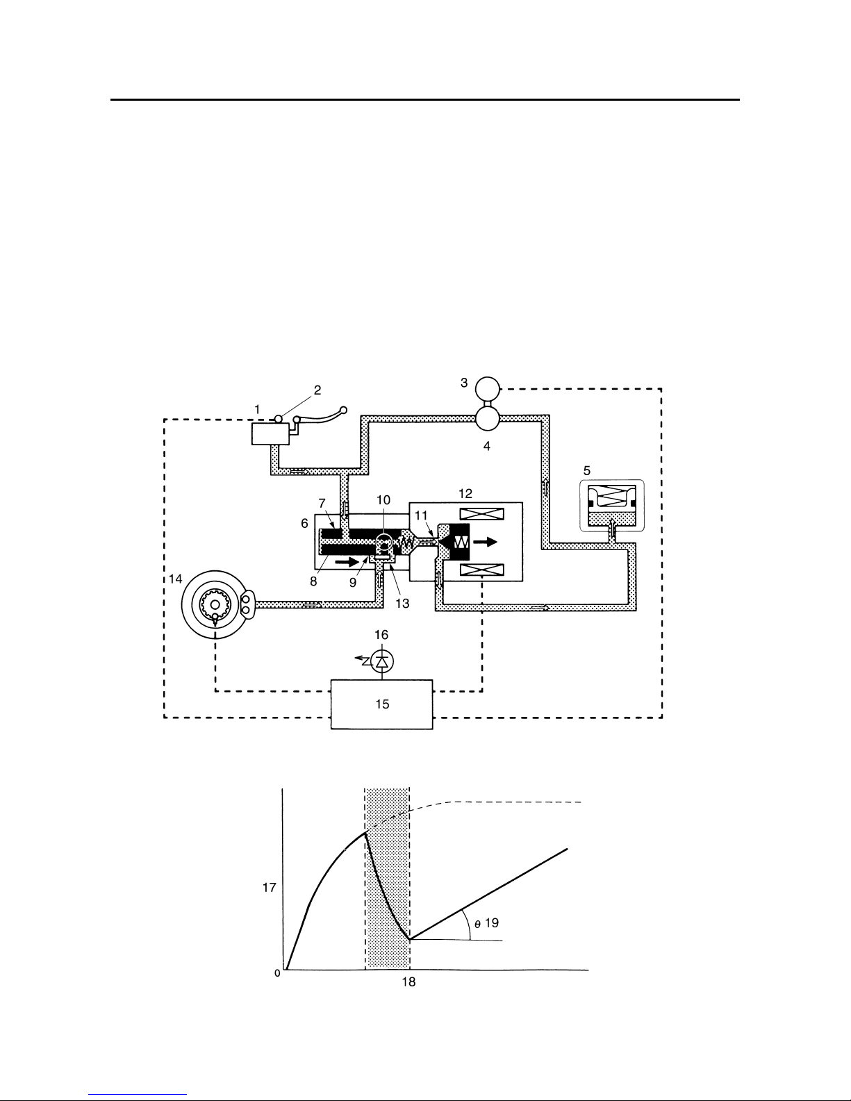
Emergency braking (ABS activated)
1.Depressurized state
When the front wheel is about to lockup, port D “11” of the solenoid valve is opened by the
“depressurization” signal transmitted from the ABS ECU. When this occurs, the spool of the flow
control valve compresses the return spring and closes port B “9”. Brake fluid that has entered
through port A “7” is restricted by the orifice “10” and the brake fluid is sent to the brake caliper via
port C “13” and port D “11”, and the buffer chamber. As a result, the hydraulic pressure in the
brake caliper is reduced.
The brake fluid stored in the buffer chamber is pumped back to the brake master cylinder by the
fluid pressure pump linked to the pump motor.
17.Brake fluid pressure
18.Time
19.Repressurizing
 Loading...