

Yamaha 1999 CW50L, 2000 CW50M, 2000 CW50N, 2000 CW50P, 1999 CW50M Service Manual
...
1999 - 2002
Downloaded from www.ScooterTime.net
MOTORCYCLE
SERVICE MANUAL
Model : CW50L, CW50M, CW50N, CW50P
4RW281972K00
*4RW281972K00*
IA-21
Downloaded from www.ScooterTime.net
NOTICE
This manual was written by the MBK INDUSTRIE primarily for use by YAMAHA dealers and their
qualified mechanics. It is not possible to put an entire mechanic's education into one manual, so it is
assumed that persons using this book to perform maintenance and repairs on YAMAHA scooters
have a basic understanding of the mechanical concepts and procedures inherent in scooter repair
technology. Without such knowledge, attempted repairs or service to this model may render it unfit to
use and/or unsafe.
MBK INDUSTRIE is continually striving to improve all models manufactured. Modifications and sig-
nificant changes inspecifications or procedures will beforwarded to allAuthorized YAMAHA dealers
and will, where applicable, appear in future editions of this manual.
DOCUMENTATION TECHNIQUE
MBK INDUSTRIE
PARTICULARLY IMPORTANT INFORMATION
This material is distinguished by the following notation:
CW50
SERVICE MANUAL
© 1997 by MBK INDUSTRIE
3st Edition, April 1997
All rights reserved. Any
reprinting or unauthorized use
without the written
)ermission of MBK INDUSTRIE
is expressly prohibited.
/_ The safetyAlert Symbol meansATTENTION! BECOMEALERT! YOUR
SAFETY IS INVOLVED!
r.IIY/-'1:I_11_[¢]1 Failure to follow WARNING instructions could result in severe injury or
death to the scooter operator, a bystander, or a person inspecting or
repairing the scooter.
CAUT}ONi: A CAUTION indicates special precautions that must be taken to avoid
damage to the scooter.
NOTE: ANOTE provides key information to make procedures easier or clearer.

IA-31
Downloaded from www.ScooterTime.net
HOW TO USE THIS MANUAL ® ® ILLUSTRATEDSYMBOLS
CONSTRUCTION OF THIS MANUAL
This manual consists of chapters for the main categories of subjects. (See <<illustratedsymbols). Illustrated symbols _ to _ are designed as
1st title (_) This is a chapter with its symbol on the upper right of each page. (_ L_ thumb tabs to indicate the chapter's number and
2nd tiUe Q This tiUeappears on the upper of each page on the left of the chapter symbol. (For I=-I I _ content.
3rd title _) This is a final title. _ General information
MANUAL FORMAT _ _ _ Periodic inspection and adjustment
tion has been compiled to provide the mechanic with an easy to read, handy reference that contains @ Carburetion
comprehensive explanations of all disassembly, repair, assembly, and inspections. _ Chassis
A set of particularly important procedure (_)is placed between a line of asterisks "* "with each step _ ® _ Electrical
IMPORTANT FEATUREsPrecededby" " "" II :1 _)Troubleshooting
• Data and a special tools are framed in a box preceded by a relevant symbol®. _ _ Illustrated symbols _ to _ are used to identify
alignments mark Q, the others being indicated by an alphabetical letter in a box_), the specifications appearing in the text.
• An encircled numeral ® indicates a part name, and an encircled alphabetical letter data for an _
• A condition of a faulty component will precede an arrow symbol and the course of action required
thesymbol(_). ' _ Fillingfluid
Each chapter provides exploded diagrams are before each disassembly section for ease in identify- @Tightening
EXPLODED DIAGRAM <_ i_ @ Special tool
ing correct disassembly and assembly procedures. @ Wear limit, clearance
the chapter (<Periodicinspection and adjustment)) the 3rd title appears.) I_
z(t_Specifications
@ i @ _ Lubricant
@ Engine speed
OVA
' _. :_-_.,_.._,';__..... :;"--L'..'._,_ _ _ _ Illustrated symbols _ to @ inthe exploded dia-
"",_ gram indicate grade of lubricant and location of
_- .- _';"............. !_ .... _ _ _I @ I _ , _ Apply engine oil
__,_., @ Apply gear oil
--i --| --_ _) Apply molybdenum disulfide oil
lubrication point.
®_---- _--_1'¢_ ":_""';_"- I J _ _ @ grease
r/,_, j _| [E,;2_;c_E _-- _ _ @ Apply molybdenum disulfide grease
:,T_...:.:....C.__,_I_:;-_,..,_tF-.-"'_ _:_'_...... _1___ _ Apply wheel bearing grease
-_-_, :_"':'_- _ _ _ @Applylockingagent(THREADLOCK®)
__--:5: , Apply lightweight lithium-soap base
@
Use
new
one
A-4 I
Downloaded from www.ScooterTime.net
INDEX
SPECIFICATIONS
PERIODIC INSPECTION I _ I
AND ADJUSTMENT I'"sP
ENGINEOVERHAUL
CARBURETION
CHASSIS
ELECTRICAL
TROUBLESHOOTING
I
Downloaded from www.ScooterTime.net
I1 II!
1
[!

I GEN
Downloaded from www.ScooterTime.net
CHAPTER 1.
GENERAL INFORMATION
SCOOTER IDENTIFICATION ....................................................................... A-8
VEHICLE IDENTIFICATION NUMBER ................................................... A-8
ENGINE SERIAL NUMBER .................................................................... A-8
IMPORTANT INFORMATION ...................................................................... A-8
ALL REPLACEMENT PARTS ................................................................ A-8
GASKETS, OIL SEALS, AND O-RINGS ................................................. A-8
LOCK WASHERS/PLATES AND CO'I-I'ER PINS .................................. A-8
BEARINGS AND OIL SEALS .................................................................. A-8
CIRCLIPS ................................................................................................ A-9
SPECIAL TOOLS .......................................................................................... A-9
FOR TUNE UP ........................................................................................ A-9
FOR ENGINE SERVICE ......................................................................... A-9
FOR CHASSIS SERVICE ..................................................................... A-10
FOR ELECTRICAL COMPONENTS ..................................................... A-10
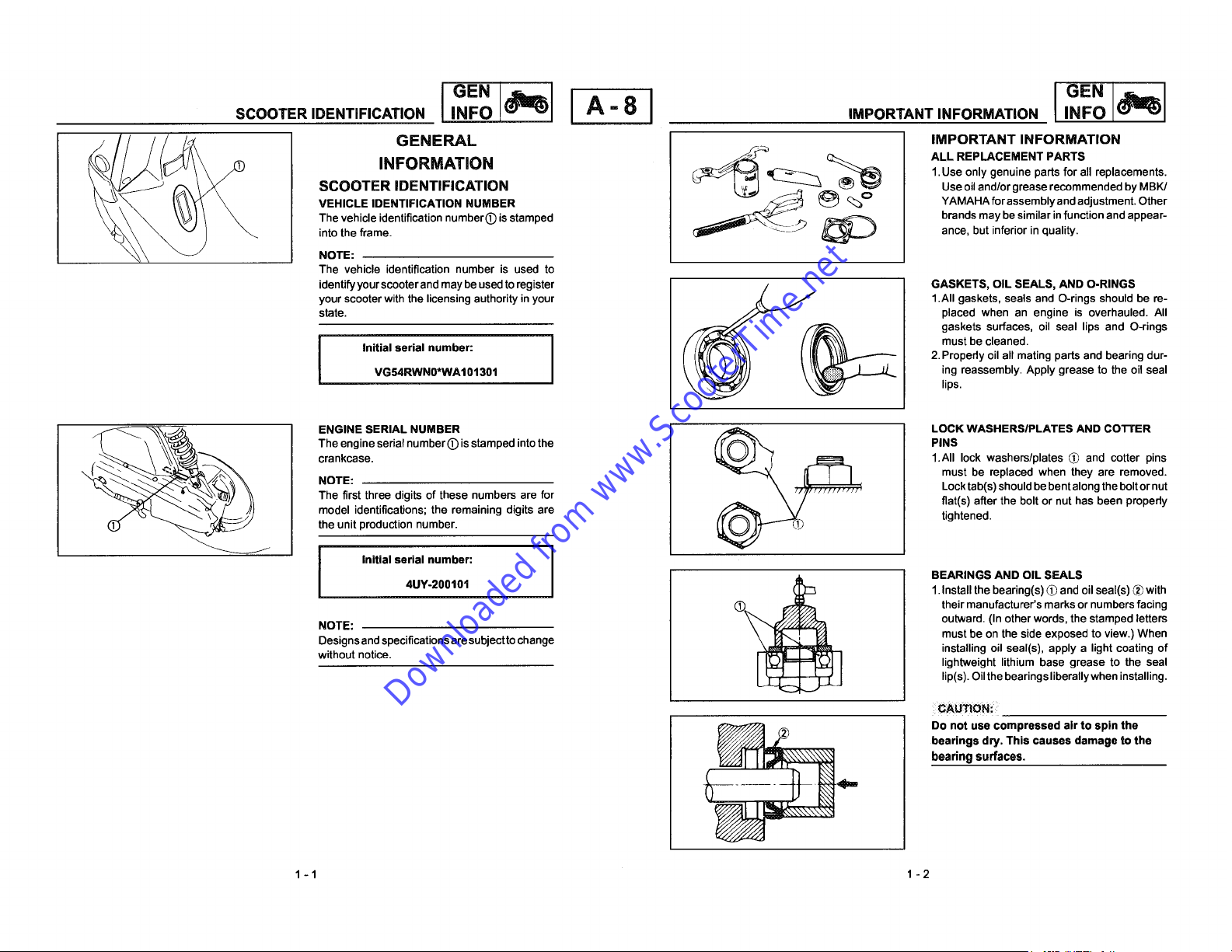
SCOOTER IDENTIFICATION INFO A - 8 IMPORTANT INFORMATION INFO
Downloaded from www.ScooterTime.net
IGE"I 1 I°E"
INFORMATION ALL REPLACEMENT PARTS
SCOOTER IDENTIFICATION Useoil and/or grease recommended by MBK/
VEHICLE IDENTIFICATION NUMBER _'-.._ _ _O YAMAHAforassemblyandadjustment.Other
The vehicle identification numbere isstamped _._ __ _ brands may besimilar in function and appear-
_ _ _ into the frame, ance, but inferior in quality.
_ crankcase. _ 1.All lock washers/plates (_ and cotter pins
NOTE:
The vehicle identification number is used to
your scooter with the licensing authority inyour 1.All gaskets, seals and O-rings should be re-
state, placed when an engine is overhauled. All
I Initial serial number: I must be cleaned.
identifyyourscooterand maybe usedto register __(_ GASKETS, OIL SEALS, AND O-RINGS
The engine serial number@ is stamped into the PINS
NOTE: _ Locktab(s) should bebent along the boltornut
The first three digits of these numbers are for _MHr,IH' flat(s) after the bolt or nut has been properly
model identifications; the remaining digits are tightened.
the unit production number.
I Initial serial number:
NOTE: outward. (In other words, the stamped letters
Designs and specifications aresubjectto change must be on the side exposed to view.) When
without notice, installing oil seal(s), apply a light coating of
VG54RWN0*WA101301 ing reassembly. Apply grease to the oil seal
4UY-200101 1.Install the bearing(s) (_ and oil seal(s) ® with
O_ BEARINGS AND OIL SEALS
1. Use only genuine parts for all replacements.
gaskets surfaces, oil seal lips and O-rings
2.Properly oil all mating parts and bearing dur-
lips.
must be replaced when they are removed.
their manufacturer's marks or numbers facing
lightweight lithium base grease to the seal
lip(s). Oil the bearings liberally when installing.
CAUTION: _
1-1 1 -2
__ bearings dry. This causes damage to the
bearing surfaces.
Donotusecompressedair tospin the

IMPORTANT INFORMATION/SPECIAL TOOLS INFO _ A" 9 J SPECIAL TOOLS INFO
Downloaded from www.ScooterTime.net
CIRCLIPS Flywheel magneto puller
c_) clips once they have been removed. Replace
[_ fore reassembly. Always replace piston pin
bent circlips. When installing a circlip _) make FOR ENGINE SERVICE
sure that the sharp edge _ is positioned
opposite to the thrust L_ itreceives. See the
sectional view.
Shaft
SPECIAL TOOLS 90890-01135 90890_0t_'_ f{_
plete and accurate tune-up and assembly. Us-
ing the correct special tool will help prevent
damage caused by the use of improper tools or
improvised techniques.
The proper special tools are necessary for com- _ _ (_
Inductive tachometer ] Crankshaft installing tool set Clutch serving nutwrenc_
FOR TUNE UP 90890-01411 (_ \_';_:i"
I°E"I IGE"I
care,u,, e- 08 0-019
Crankcase separating tool Flywheel holding tool
90890-01277 (_) ._
90890-03113 1 90890-01274 _) ;_'#--'_ 90890-01348
Ignition checker Sheave holder Clutch spring holderri a f_ c-_
__ 90890-01275 _)
g0890_0_4_ go8go.01_01 00890_01010®g°890°1_®___'_-__<"_>_-
Oil Seal Guide
90890-01409 (D
Oil Seal Driver _/
1-3 1-4
SPECIAL TOOLS I
Downloaded from www.ScooterTime.net
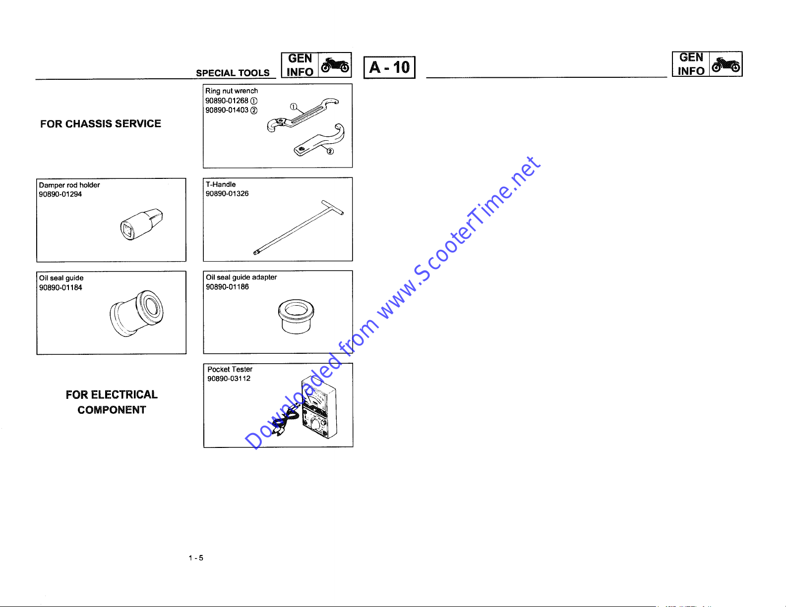
Ring nut wrench
90890-01268 _ ,_ _
90890-01403 _)
FOR CHASSIS SERVICE
Damper rod holder T-Handle
90890o01294 90890-01326
Oil seal guide Oil seal guide adapter
90890-01184 90890-01186
GEN
I
'NFO _1_1 IA _ol I
- I.FO_1
Pocket Tester
FORCOMPONENTELECTRICAL 90890-03112 _
1-5

Downloaded from www.ScooterTime.net

-/___/
Downloaded from www.ScooterTime.net
Ill
{J
IsPEc_'1tA-131 IsPEc_1
Downloaded from www.ScooterTime.net
CHAPTER 2.
SPECIFICATIONS
GENERAL SPECIFICATIONS .................................................................... A-14
MAINTENANCE SPECIFICATIONS ........................................................... A-15
ENGINE ................................................................................................ A-15
CHASSIS .............................................................................................. A-16
ELECTRICAL .......................................................................................... B-1
CABLE ROUTING ......................................................................................... B-2

GENERAL SPECIFICATIONS I SPEc /'(_'1 IA-41 GENERAL SPECIFICATIONS I SPEC /(_i'
Downloaded from www.ScooterTime.net
SPECIFICATIONS Model CW50
GENERAL SPECIFICATIONS Clutch type: Dry, centrifugal automatic
Model CW50 Primary reduction system Helical gear
Dimensions: Primary reduction ratio 52/13 (4.000)
Overall length 1,740 mm (68.5 in) Secondary reduction system Spur gear
Overall width 665 mm (26.2 in) Secondary reduction ratio 43/13 (3.3077)
Overall height 1,050 mm (41.3 in) Transmission V-belt
Seat height 745 mm (29.3 in) Operation Automatic
Wheelbase 1,170 mm (46.0 in) Chassis:
Minimum ground clearance 125 mm (4.9 in) Frame type Steel tube underbone
Basicweight: Casterangle 27°
With oil and full fuel tank 78 kg (172 Ib) Trail 90 mm (3.54 in)
Minimumturningradius: 1,800mm(70.9in) Tire:
Engine: Type Tubeless
Type Air-cooled 2-stroke, gasoline torque induction. Size front 120/90- 10
Cylinder arrangement Single cylinder, Vertical rear 130/90 -10
Displacement 49 cm3 Manufacturer front DUNLOP (TRAIL MAX)
Bore x stroke 40 x 39.2 mm (1.57 x 1.54 in) MICHELIN (REGGAE TL)
Compression ratio 7.01 : 1 rear DUNLOP (TRAIL MAX)
Starting system Electric and kick starter MICHELIN (REGGAE TL)
Lubricationsystem: Separatelubrication (Yamaha Autolube ) Tire pressure(coldtire):
Oiltype or grade: Up to 90 kg (198 Ibs) load
Engine oil Semi-synthetic oil in accordance to the Front 100 kPa (1.00 kgf/cm2,15 psi)
Transmission oil SAE 10W30 type SE motor oil 90 kg(198 Ibs) ~ maximum load
Oil capacity: Front 100 kPa (1.00 kgf/cm2,15 psi)
Engine oil: Rear 150 kPa (1.50 kgf/cm2,21 psi)
Total amount 1.3 L (1.14 Imp qt, 1.37 US qt) Brake:
Transmission oil: Front brake type Disc brake
Periodic oil change 0.11 L (0.10 Impqt, 0.12 US qt) Operation Right hand operation
Total amount 0.13 L (0.11 Impqt, 0.13 US qt) Rear brake type Drum brake
Airfilter: Wettypeelement Operation Lefthandoperation
Fuel: Suspension:
Type Regular unleaded gazoline (RON 91 mini) Front Telescopic fork
Tankcapacity 4.6L(1.01Impgal,1.21USgal) Rear Unitswing
Carburetor: Shockabsorber:
Type PHBN12HS Front Coil spring/Oil damper
Manufacturer DELL'ORTO Rear Coil spring/Oil damper
Spark plug: !Wheel travel:
Type/Manufacturer BR8HS/NGK Frontwheel travel 62 mm (2.44 in)
Gap 0.5 - 0.7 mm (0.020 ~ 0.028 in) Rear wheel travel 60 mm (2.36 in)
API TC TS C3 standard. Rear 125 kPa (1.25 kgf/cm2,18 psi)
Transmission:
Maximumload-exceptscooter 152kg(335Ibs)
2-1 2-2
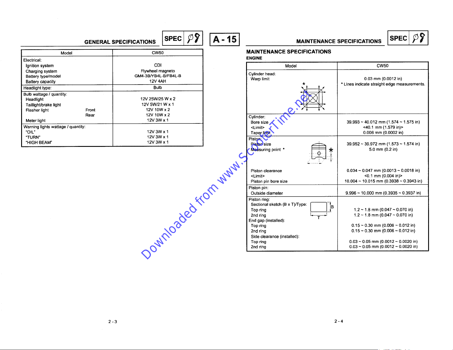
I P'=c IA-lSI MAINTENANCE SPECIFICATIONS I SPEc /'_'1
Downloaded from www.ScooterTime.net
Model CW50 MAINTENANCESPECIFICATIONS
Electrical: ENGINE
Ignitionsystem CDI Model CW50
Charging system Flywheel magneto
Battery type/model GM4-3B/YB4L-B/FB4L-B Cylinder head:
Battery capacity 12V 4AH Warp limit 0.03 mm (0.0012 in)
Headlight type: Bulb __
Bulb wattage / quantity:
Taillight/brake light 12V 5W/21 W x 1
Flasher light Front 12V 10W x 2 -_'_ _'_
Rear 12V 10W x 2 Cylinder:
Meter light 12V 3W x 1 Bore size 39.993 - 40.012 mm (1.574 ~ 1.575 in)
Warning lights wattage / quantity: <Limit> <40.1 mm (1.579 in)>
"OIL" 12V 3W x 1 Taper limit 0.006 mm (0.0002 in)
"TURN" 12V 3W x 1 Piston:
"HIGH BEAM" 12V 3W x 1 MeasuringPiSt°nsize point . _ _¢' 39.952 - 39.9725.0mmmm(0.2(1.573in)~ 1.574 in)
Piston clearance 0.034 ~ 0.047 mm (0.0013 - 0.0018 in)
<Limit> <0.1 mm (0.004 in)>
Piston pin bore size 10,004 ~ 10.015 mm (0.3938 - 0.3943 in)
Piston pin:
Outside diameter 9.996 ~ 10.000 mm (0.3935 ~ 0.3937 in)
Piston ring:
,k * Lines indicate straight edge measurements.
2-3 2-4
Top ring 1.2 ~ 1.8 mm (0.047 ~ 0.070 in)
Sectional sketch (B x T)/Type: L_j_ B
2ndring - T - 1.2 -1.8 mm (0.047~ 0.070 in)
End gap (installed):
Top ring 0.15 ~ 0.30 mm (0.006 - 0.012 in)
2nd ring 0.15 ~ 0.30 mm (0.006 ~ 0.012 in)
Side clearance (installed):
Top ring 0.03 - 0.05 mm (0.0012 - 0.0020 in)
2nd ring 0.03 - 0.05 mm (0.0012 ~ 0.0020 in)

MAINTENANCE SPECIFICATIONS IsPECIA-161 MAINTENANCE SPECIFICATIONS
Downloaded from www.ScooterTime.net
Model CW50 CHASSIS
Crankshaft: Model CW50
E- No/Size of steel balls:
B__:J Steering system:
Crank width "A" 37.90 - 37.95 mm (1.492 - 1.494 in) Lower 22 pcs (3/16 in)
Runout limit "C" 0.03 mm (0.0012 in) Front suspension:
Connecting rod big end side clearance "D" 0.2 - 0.5 mm (0.008 - 0.020 in) Front fork travel 70 mm (2.75 in)
iAutomatic centrifugal clutch: Spring Rate (K1) 10.8 N/ram (1.08 kg/mm, 60.46 Ib/in)
Shoe thickness 4.0 mm (0.16 in) Stroke (K1) 0 ~ 40 mm (0 ~ 1.57 in)
<Wear limit> <2.5 mm (0.10 in)> Spring Rate (K2) 14.4 N/ram (1.44 kg/mm, 80.61 Ib/mm)
Clutch shoe spring free length 26.2 mm (1.03 in) Stroke (K2) 40 ~ 77 mm (1.57 in ~ 3.03 in)
Clutch-in revolution 3.200 ~ 3.600 r.p.m. Optional spring No
Clutch-stall revolution 6.300 - 6.900 r.p.m. Rear suspension:
V-belt: Shock absorber travel 60 mm (2.36 in)
Width 15 mm (0.59 in) Spring free length 202 mm (7.95 in)
<Wearlimit> <13.5mm(0.53in)> Springfittinglength 187.5mm(7.38in)
Transmission: Spring Rate 32.5 N/ram (3.25 kg/mm, 181.93 Ib/mm)
Main axle runout limit 0.08 mm (0.003 in) Stroke 0 ~ 44 mm (0 ~ 1.73 in)
Driveaxlerunoutlimit 0.08mm(0.003in) Optionalspring No
Kick starter: Wheels:
Type Ratchet type Front wheel type Cast wheel
Kick clip tension 150 ~ 250 g (5.3 - 8.8 oz) Rear wheel type Cast wheel
Carburetor: Front wheel size MT 3.50 xl0
I.D. mark PHBN12HS Material Aluminium
Main jet (M.J.) # 93 Front wheel size MT 3.50 xl0
Main airjet (M.A.J.) 2.0 Material Aluminium
Jet needle (J.N.) A21-3/5 Rim runout limit:
Needle jet (N.J.) 2.110 Front 2.0 mm (0.08 in)
Cutaway (C.A.) 4.0 Rear 2.0 mm (0.08 in)
Pilot jet (P.J.) # 36 Front disk brake:
Bypass (B.P.1) 0.8 Type Single disk
Pilot air screw (A.S.) 1-5/8 _+114out Diameter & thickness 155 x 3.5 mm (6.102 x 0.137 in)
Valve seatsize (V.S.) 1.2 Pad thickness 3.25 mm (0.127 in)
Starter jet (G.S.1) # 40 <Wear limit> <0.8 mm (0.03 in)>
Float height (F.H.) 15 - 17 mm (0.59 ~ 0.67 in) Master cylinder inside diameter 11 mm (0.43 in)
Fuel height (F.L.) 20.5 ~ 22.5 mm (0.80 ~ 0.88 in) Caliper cylinder inside diameter 30 mm (1.18 in)
(Center offloat chamber / Fuel height) Brake fluid type DOT #3 or DOT #4
Engineidlespeed 1800_+200rpm Reardrumbrake:
Reedvalve: Type Leading,trailing
Valve stopper height 4.0 ~ 4.4 mm (0.157 ~0.173 in) Drum inside diameter 110 mm (4.33 in)
Reed valve clearance 0.2 mm (0.008 in) <Wear limit> <110.5 mm (4.35 in)>
Lubrication system: Autolube pump Lining thickness 4.0 mm (0.16 in)
Stroke 2.62 mm (0.10 in) <Wear limit> <2.0 mm (0.08 in)>
Bore 0.5 mm (0.02 in) Spring free length 54 mm (2.125 in)
2-5 2-6
Steeringbearingtype Ballbearing
Upper 22 pcs (3/16 in)
Front brake lever freeplay: 10 ~ 20 mm (0.4 ~ 0.8 in)
Rear brake leverfreeplay: 10 ~ 20 mm (0.4 - 0.8 in)
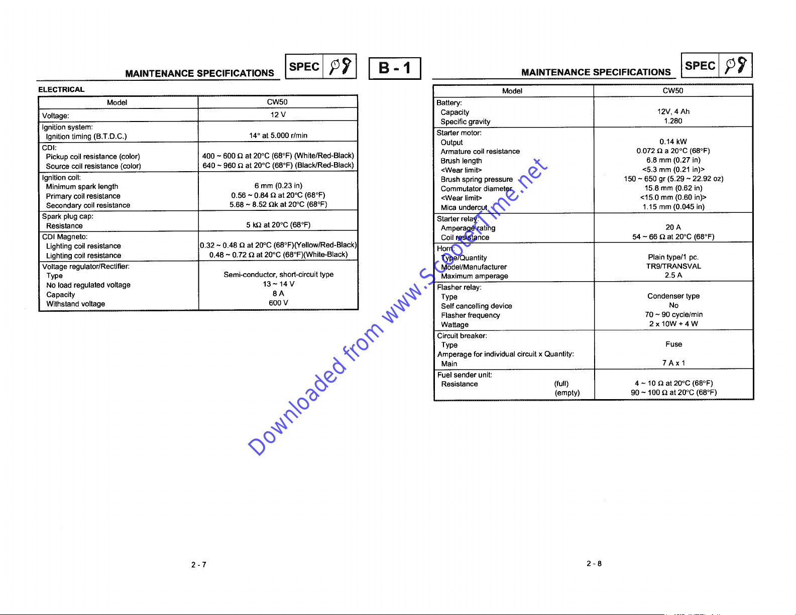
M.,.TE.A.OE.PEC,..C..,O.SIs Ec B-1I M.,.TE...CES.EC,F,C.T,O.SISPEC
Downloaded from www.ScooterTime.net
ELECTRICAL Model CW50
Model CW50 Battery:
Voltage: 12 V Capacity 12V, 4 Ah
Ignition system: Specific gravity 1.280
Ignition timing (B.T.D.C.) 14° at 5.000 r/rain Starter motor:
CDI: Armature coil resistance 0.072 _ a 20°C (68°F)
Pickup coil resistance (color) 400 ~ 600 Q at 20°C (68°F) (White/Red-Black) Brush length 6.8 mm (0.27 in)
Source coil resistance (color) 640 ~ 960 Q at 20°C (68°F) (Black/Red-Black) <Wear limit> <5.3 mm (0.21 in)>
Ignition coil: Brush spring pressure 150 - 650 gr (5.29 ~ 22.92 oz)
Minimum spark length 6 mm (0.23 in) Commutator diameter 15.8 mm (0.62 in)
Primary coil resistance 0.56 ~ 0.84 Qat 20°C (68°F) <Wear limit> <15.0 mm (0.60 in)>
Secondary coil resistance 5.68 - 8.52 Qk at 20°C (68°F) Mica undercut 1.15 mm (0.045 in)
Spark plug cap: Starter relay:
Resistance 5 k.Qat 20°C (68°F) Amperage rating 20 A
CDI Magneto: Coil resistance 54 - 66 _ at 20°C (68°F)
Lighting coil resistance 0.32 ~ 0.48 Q at 20°C (68°F)(Yellow/Red-Black) Horn:
Lighting coil resistance 0.48 ~ 0.72 Q at 20°C (68°F)(White-Black) Type/Quantity Plain type/1 pc.
Voltage regulator/Rectifier: Model/Manufacturer TR9/FRANSVAL
Type Semi-conductor, short-circuit type Maximum amperage 2.5 A
No load regulated voltage 13 ~ 14 V Flasher relay:
Capacity 8 A Type Condenser type
Withstand voltage 600 V Self cancelling device No
Output 0.14 kW
Flasher frequency 70 - 90 cycle/rain
Wattage 2 x 10W + 4 W
Circuit breaker:
Type Fuse
Amperage for individual circuit x Quantity:
Main 7 A x 1
Fuel sender unit:
Resistance (full) 4 - 10_ at 20°C (68°F)
(empty) 90 - 100 _ at 20°C (68°F)
2-7 2-8

CA..E.OUT,.OIS" clPIIB'2 CA°LE.O°T,.OIS"EclP I
Downloaded from www.ScooterTime.net
_3) Rim [] Do not cover the frame number. _) Handlebar [] The right handlebar switch leads must pass along the underside
_) Tire [] Attach the brake hose, starter switch cable and the brake cable _) Left handle bar switch of the handlebar, then behind the boss on the lower handlebar
® Brake disc together behind the horn bracket. ® Right handlebar switch cover.
Brake caliper [] The throttle cable must have sufficient free play. _) Handlebar wire harness holder [] Pass the couplers behind the speedometer cable, and after
_) Brake hose guide (Lower) [] Clamp the brake hose into the upper holder. _ Flasher relay connecting them, fit them under the right side of the
® Brake hose guide (Upper) [] With a band tie the choke cable, the throotle cable and the rear _) Speedometer cable speedometer.
Throttle cable brake cable to the left side, the wire harness to the right side of _) Throttle cable [] The left handlebar switch leads must pass along the underside of
® Wire harness the frame. ® Lower handlebar cover the handlebar, then in front of the boss on the lower handlebar
Speedometer cable (9) Front brake hose cover.
Brake hose _ Flasher ground [] Attach the front flasher ground to the handlebar.
_) Choke cable [] The throttle cable must pass in front of the handlebar.
@ Rear brake cable [] The brake light leads must pass along the underside of the
[] Pass the flasher relay leads under the handlebar.
handlebar (left and right).
[] The wire harness holder must pass over the handlebar.
[] The brake hose union bolt must touch the right side of the boss.
o I
%
[]
2-9 2-10
OASLERO°T,NOISPECl;]IB'3 Is'c
Downloaded from www.ScooterTime.net
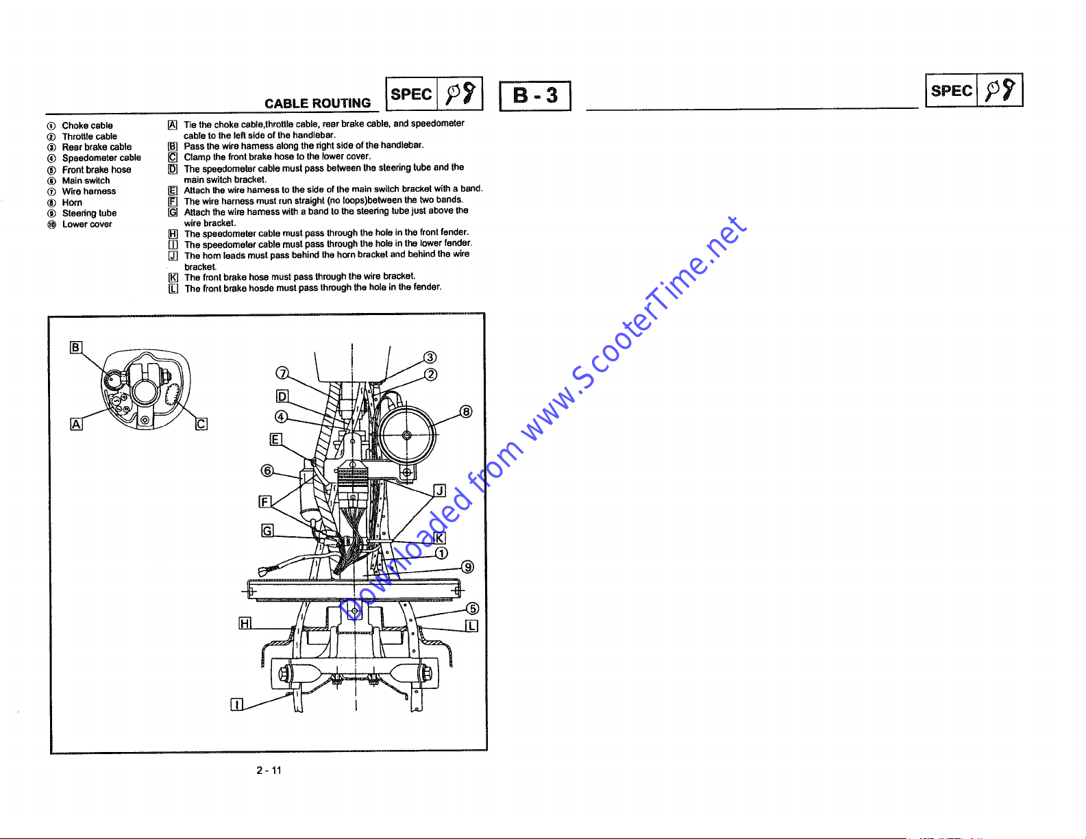
(_) Choke cable [] Tie the choke cable,throttle cable, rear brake cable, and speedometer
(_) Throttle cable cable to the left side of the handlebar.
® Rear brake cable [] Pass the wire harness along the right side of the handlebar.
(_ Speedometer cable [] Clamp the front brake hose to the lower cover.
® Front brake hose [] The speedometer cable must pass belween the steering tube and the
(_ Main switch main switch bracket.
(_) Wire harness [] Attach the wire harness to the side of the main switch bracket with a band.
® Horn [] The wire harness must run straight (no loops)between the two bands.
® Steedng tube [] Attach the wire hamess with a band to the steedng tube just above the
Lower cover wire bracket.
[] The speedometer cable must pass through the hole in the front fender.
[] The speedometer cable must pass through the hole in the lower fender.
[] The horn leads must pass behind the horn bracket and behind the wire
bracket.
[] The front brake hose must pass through the wire bracket.
[] The front brake hosde must pass through the hole in the fender.
T
I I = .....
2-11

Downloaded from www.ScooterTime.net

I INSP
Downloaded from www.ScooterTime.net
BEI I
- I
CHAPTER 3.
PERIODIC INSPECTION AND ADJUSTMENT
INTRODUCTION ........................................................................................... B-7
PERIODIC MAINTENANCE/LUBRICATION INTERVALS ........................... B-7
COVERS ....................................................................................................... B-7
REMOVAL ............................................................................................... B-7
INSTALLATION ....................................................................................... B-8
ENGINE ........................................................................................................ B-9
ENGINE IDLE SPEED ADJUSTMENT ................................................... B-9
THROTTLE CABLE FREE PLAY ADJUSTMENT .................................. B-9
SPARK PLUG INSPECTION ................................................................ B-10
AUTOLUBE PUMP AIR BLEEDING ..................................................... B-10
ENGINE OIL LEVEL INSPECTION ...................................................... B-11
TRANSMISSION OIL REPLACEMENT ................................................ B-11
AIR CLEANER ELEMENT CLEANING ................................................. B-12
CHASSIS .................................................................................................... B-12
FRONT BRAKE LEVER FREE PLAY ADJUSTMENT .......................... B-12
REAR BRAKE LEVER FREE PLAY ADJUSTMENT ............................ B-12
BRAKE PADS INSPECTION ................................................................ B-12
BRAKE SHOES INSPECTION ............................................................. B-13
AIR BLEEDING (HYDRAULIC BRAKE SYSTEM) ................................ B-13
STEERING HEAD ADJUSTMENT ........................................................ B-14
TIRE INSPECTION ............................................................................... S-14
WHEEL INSPECTION .......................................................................... B-15
CABLE INSPECTION AND LUBRICATION .......................................... B-15
LEVER LUBRICATION ......................................................................... B-15
CENTERSTAND LUBRICATION .......................................................... B-15
REAR SHOCK ABSORBER ................................................................. B-15
ELECTRICAL .............................................................................................. B-16
BATTERY INSPECTION ....................................................................... B-16
FUSE INSPECTION .............................................................................. B-16
HEADLIGHT BEAM ADJUSTMENT ....................................................... C-1
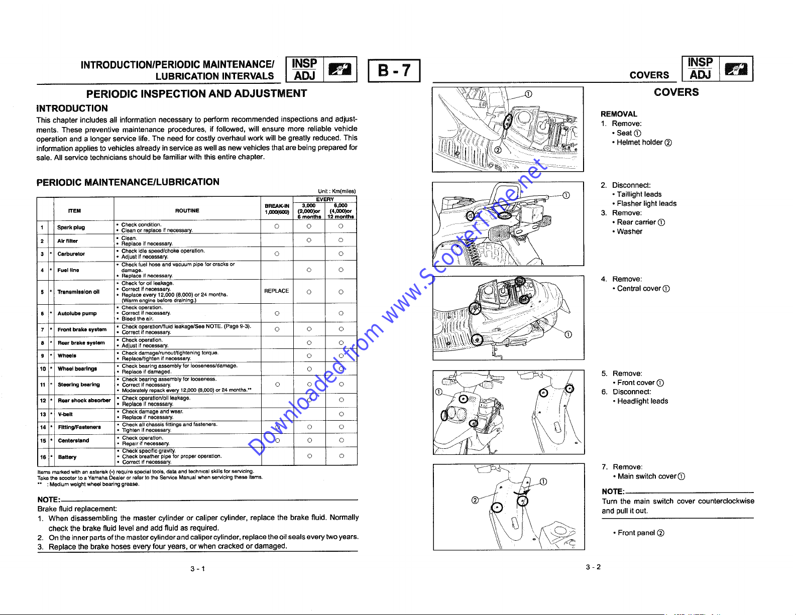
INTRODUCTIONIPERIOOIC MAINTENANCEI I INSP I I I INSP I
Downloaded from www.ScooterTime.net
LUBRICATION INTERVALS ADJ IF_ B - 7 COVERS _ _
PERIODIC INSPECTION AND ADJUSTMENT _ I__ COVERS
ments. These preventive maintenance procedures, if followed, will ensure more reliable vehicle • SeatC)
This chapter includes all information necessary to perform recommended inspections and adjust- i_ d REMOVAL
INTRODUCTION
, -! 1. Remove:
information applies to vehicles already in service as well as new vehicles that are being prepared for ,/___I_ .Helmet holder (_)
sale. All service technicians should be familiar with this entire chapter.
operation and a longer service life. The need for cosUy overhaul work will be greaUy reduced. This i_<_ _ _ __(___
Unit : Km(miles) _ • Taillight leads
ITEM ROUTINE 1,000(600) (2,000)or (4,000)or 3. Remove:
PERIODIC MAINTENANCE/LUBRICATION _ _!_::=_-_ 2. Disconnect:
2 Air filter Replace if necessary.
3 Carburetor Adjustifnecessary. O O
1 Spark plug Clean.Cleanor replace if necessary. O O _J _ _ • Washer
4 Fuelline damage. O O
S i Transmission oll Correct if necessary. • Central cover (_
6 Autolube pump Correct if necessary. © O
7 Front brake system Check operation/fluid leakage/See NOTE. (Page 9-3).
8 Rear brake system Adjust if necessary. O O
9 Wheels Check damage/runout/tightening torque.
1( Wheel bearings Check bearing assembly for looseness/damage.
11 Steering bearing Correct if necessary. © O © • Front cover (D
1". Rear shock absorber Check operation/oil leakage, O o • Headlight leads
1,'. V-belt Check damage and wear.
IL Fitting/Fasteners Check all chassis fittings and fasteners.
1,= Centerstand e_.
1( Battery Check breather pipe for proper operation. O O
Items marked with an asterisk I Irequire special tools, data and technical skillsfor servicing. 7. Remove:
Takethe scooter to a Yamaha Dealer or refer to the Service Manual when servicing these items. • Main switch cover (D
•* :Medium weight wheel bearing grease. _ NOTE:
Check condition. O © © • Rear carrier C)
Check idle speed/choke operation.
Check fuel hose and vacuum pipe for cracks or
Replace if necessary, 4. Remove:
Replace every 12,000 (8,000) or 24 months.
(Warm engine before draining.)
Check operation.
Bleed the air.
Correct if necessary. O O O
Check for oil leakage,
Check operation, __
Replace/tighten if necessary. O ©
Check bearing assembly for looseness.
Moderately repack every 12,000 (8,000) or 24 months.** 6. Disconnect:
Replace if necessary.
Replace if necessary. O
33ghtan if necessary, © O ©
Repair if necessary. O O ©
Check specific gravity,
CheckReplace if damaged,operation. © O _ _ 5. Remove:--
Correct if necessary.
BREAK-IN 3,000 8.000 • Flasher light leads
REPLACE O ©
EVERY
8 months 12 months
I
NOTE: Turn the main switch cover counterclockwise
Brake fluid replacement: and pull itout.
1. When disassembling the master cylinder or caliper cylinder, replace the brake fluid. Normally
check the brake fluid level and add fluid as required. _ • Front panel (_
2. On the inner parts of the mastercylinder and caliper cylinder, replacethe oilseals every two years.
3. Replace the brake hoses every four years, or when cracked or damaged.
3-1 3-2
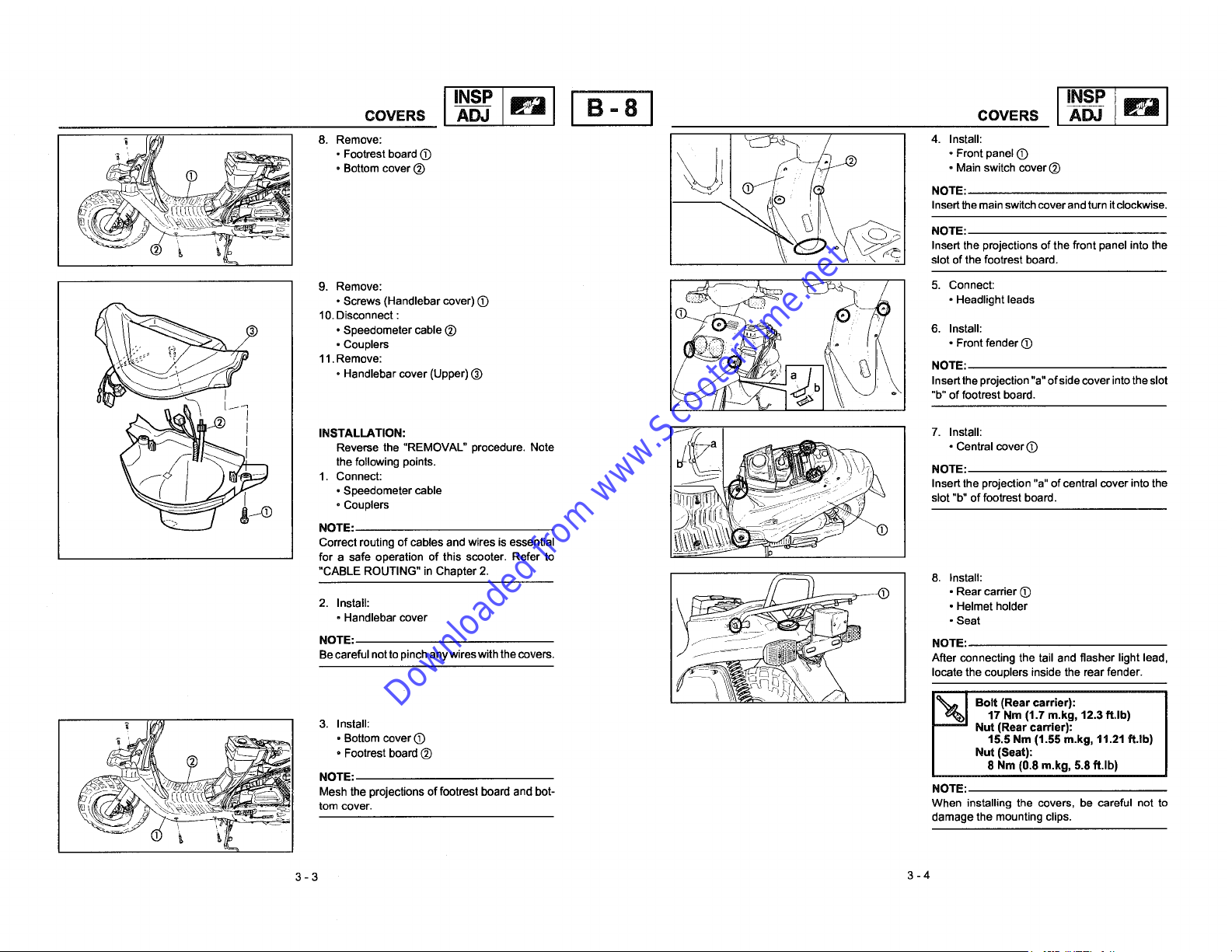
COVERS I INSP_ _ffr_ I B-8 I COVERS I INSP_ _1
Downloaded from www.ScooterTime.net
, _ • Footrest board (D • Front panel (D
:__ . _ NOTE:
t_ _ 8. Remove: ___ 4. Install:
_ NOTE:
• Bottom cover (_) • Main switch cover (_)
Insert the main switch cover and turn itclockwise.
Insert the projections of the front panel into the
slot of the footrest board.
• Screws (Handlebar cover) (D :::_' ; • Headlight leads
• Speedometer cable (_) 6. Install:
•Couplers •Frontfender0
11.Remove: NOTE:
oHandlebar cover (Upper) (_) Insertthe projection "a" of side cover into theslot
"b" of footrest board.
eove Connec
/ INSTALLATION: f 7. Install:
10.Disconnect :
Reverse the "REMOVAL" procedure. Note • Central coverO
the following points.
1.Connect: NOTE:
oSpeedometer cable Insert the projection "a" ofcentral cover into the
• Couplers [l_'_:_"_ _ _ slot "b" of footrest board.
Correct routing of cables and wires is essential
NOTE: _(D
for a safe operation of this scooter. Refer to
• Rear carrier (D
• Handlebar cover _ • Seat
NOTE: NOTE:
2."CABLEInstaIt:ROUTING"in Chapter 2. ___"_ "\_ __ 8. Install:
Becareful not topinch any wires with the covers. After connecting the tail and flasher light lead,
' • Footrest board (_) Nut (Seat):
_ tom cover. When installing the covers, be careful not to
_ _ _ 3. Install: - Nut (Rear carrier):
_ _ damage the mounting clips.
• Bottom cover (_) 15.5 Nm (1.55 m.kg, tl.21 ff.lb)
NOTE:
Mesh the projections offootrest board and bot- NOTE:
3-3 3-4
• Helmet holder
locate the couplers inside the rear fender.
I'1 (Rear carrier):
17 Nm (1.7 m.kg, 12.3 ft.lb)
8 Nm (0.8 rn.kg, 5.8 ft.lb)

ENGINE IDLE SPEED ADJUSTMENT _ _ B - 9 THROTTLE CABLE FREE PLAY ADJUSTMENT _
Downloaded from www.ScooterTime.net
ij j 1. Tighten: 1. Check:
• Pilot air screw O -Throttle cable free play @
Turn the pilotair screw inuntil lightly seated. Out of specification ---*Adjust.
I'"sP II I'"sP I
2. Loosen: 1.5 ~ 3.0 mm (0.06 ~ 0.12 in)
__ ENGINE IDLE SPEED ADJUSTMENT MENT
oPilot air screw
Back out from the lightly seated position. .-.:=::::::==::::=_xx=_==:_x-,=:=:=__
1-518turns out -+114 NOTE:
f_ Pilot air screw position: I
3. Start theengine and letitwarm up forseveral engine idle speed should be adjusted.
minutes.
V!IW_,I;1 _11_[¢]I First step:
For safety reasons, place the scooter on • Turn the adjuster (_) in or out until the speci-
the center stand before starting the engine, fled free play is obtained.
4, Attach: Turn in Free play increased.
• Inductive tachometer
(to the spark plug lead) Turn out Free play decreased.
--_Free play @:
Throttle cable free play adjustment steps:
Before adjusting the throttle cablefree play, the
Loosen the Iocknut (_) on the throttle cable.
'ndu°t'vetac'°meter:.ef:..0.03t1, I T0 tent,e
_WARNING
After adjusting, turn the handlebar to the
right and left, making sure that the engine
5. Check:
• Engine idle speed ::::::::":::::::==::":::::::=::*_**_::::::::::*"*"*
Out of specification -) Adjust.
1800 + 200 rlmin
6. Adjust:
• Engine idle speed
I
idling speed does not change.
Turn the throttle stop screw O inor out until
__ Adjustmentsteps:
specified idling speed is obtained.
Turning left Idling speed increased.
Turning right Idling speed decreased.
3-5 3-6
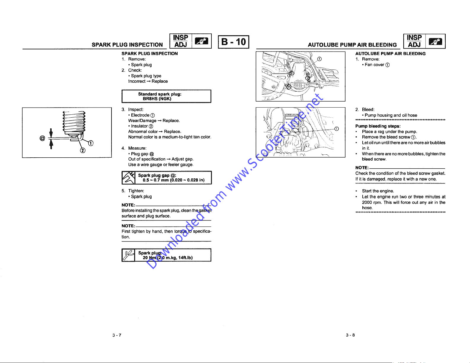
INSP
Downloaded from www.ScooterTime.net
I
SPARK PLUG INSPECTION I
SPARK PLUG INSPECTION /_ .4 AUTOLUBE PUMP AIR BLEEDING
• Spark plug ;_ ,i,/_ " Fan cover (_
2. Check: _,_'_-_H_'/I_'
• Spark plug type
Incorrect _ Replace
1. Remove: _ _ 1, Remove:
i I
@ Normal color is a medium-to-light tan color, __/_i_ i__ Remove the bleed screw (_.
3. Inspect: '/_- \\_ ' '\ \\- • Pump housing and oil hose
4. Measure: __ init.
BR8HS (NGK)
Wear/Damage _ Replace. *......................................................
• Insulator (_) _ Pump bleeding steps:
. Electrode O ___
Abnormal color _ Replace. -_ //_-_(,_.=_E_i ll\ \ \\_\ _ Place a rag under the pump.
• Plug gap @ • When there areno more bubbles, tighten the
Out of specification .-, Adjust gap. bleed screw.
Use a wire gauge or feeler gauge. NOTE:
IB-101 I
_, '_.... 2. Bleed:
'_ ""' ° Let oilrun untilthere are no more air bubbles
I_ Spark plug gap @: Check the condition of the bleed screw gasket.
5.Tighten: Starttheengine.
NOTE: hose.
Before installing the spark plug, cleanthe gasket ........ , ................. ******............. ,.........
surface and plugsurface.
NOTE:
First tighten by hand, then torque to specifica-
tion.
I_ Spark plug: I
3-7 3-8
0.5 ~ 0.7 mm (0.020 ~ 0.028 in) If it is damaged, replace it with a new one.
• Spark plug Let the engine run two or three minutes at
2000 rpm. This will force out any air in the
20 Nm (2.0 m.kg, 14ft.lb)
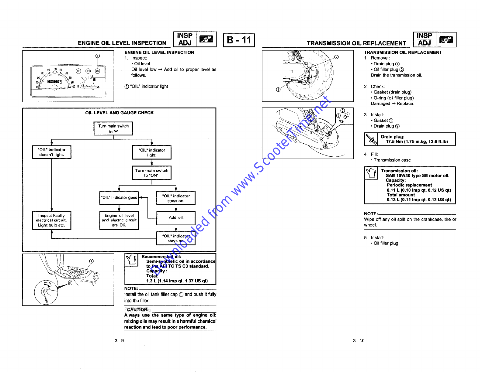
ENGINE OIL LEVEL INSPECTION B - 11 TRANSMISSION OIL REPLACEMENT _ _
Downloaded from www.ScooterTime.net
ENGINE OIL LEVEL INSPECTION _ _ " ' __ TRANSMISSION OIL REPLACEMENT
_ • Oil level _ -_) • Drain plug@
30
II
II 20_'?_- _ 8o ,=,_-_l follows. ' Drain the transmission oil.
Oillevellow -- Add oiltoproperlevelas 'i
I I'"sPI
_e__'_'_h,4050 60 70 _-- _ .(_ ,, __!_//: / "Oil filler plug_
t__"_" _'_'°°El_-_ II O "OIL" indicator light 2. Check:
OIL LEVEL AND GAUGE CHECK "_-,,"_ _ 3. Install:
T Drain plug:
Turnmainswitch _ •Drainplug(_)
doesn't light, light. 4. Fill:
I "OIL" indicator I "OIL"indicator
electricalcircuit, and electric circuit Wipe off any oil spilt on the crankcase, tire or
I Inspect FaulW Engineoil level Add oil. J
Light bulb etc. are OK. _ wheel.
to. I
I"OIL" indicatorgoes_ _ "OIL"indicator Total amount
_ 17.5 Nm (1.75 m.kg, 12.6 ft.lb)
to "ON". SAE 10W30 type SE motor oil
IT°rn a'nswitch ,r--m,.,ono.
I Periodic replacement
_ 0.11 L (0.10 Imp qt, 0.12 US qt)
stays on. I 0.13 L (0.11 Imp qt. 0.13 US qt)
_ ' NOTE:
I
_J"" • O-ring (oil filler plug)
_, ,_,_ -Gas ket(_
• Gasket (drain plug)
Damaged _ Replace.
°Transmission case
i Capacity:
t I "OlL'indicstorJ 5Install:stays on. • Oil filler plug
.°..n,..,co.,n.ccor°--
totheAPITCTSC3standard.
Capacity :
Total:
t.3 L (1.14 Imp qt, 1.37 US qt)
Install the oil tank filler cap (_ and push it fully
into the filler.
NOTE:
Always use the same type of engine oil;
mixing oils may result in a harmful chemical
reaction and lead to poor performance.
3-9 3-10
FRONT BRAKE LEVER FREE PLAYADJUSTMENT/
Downloaded from www.ScooterTime.net
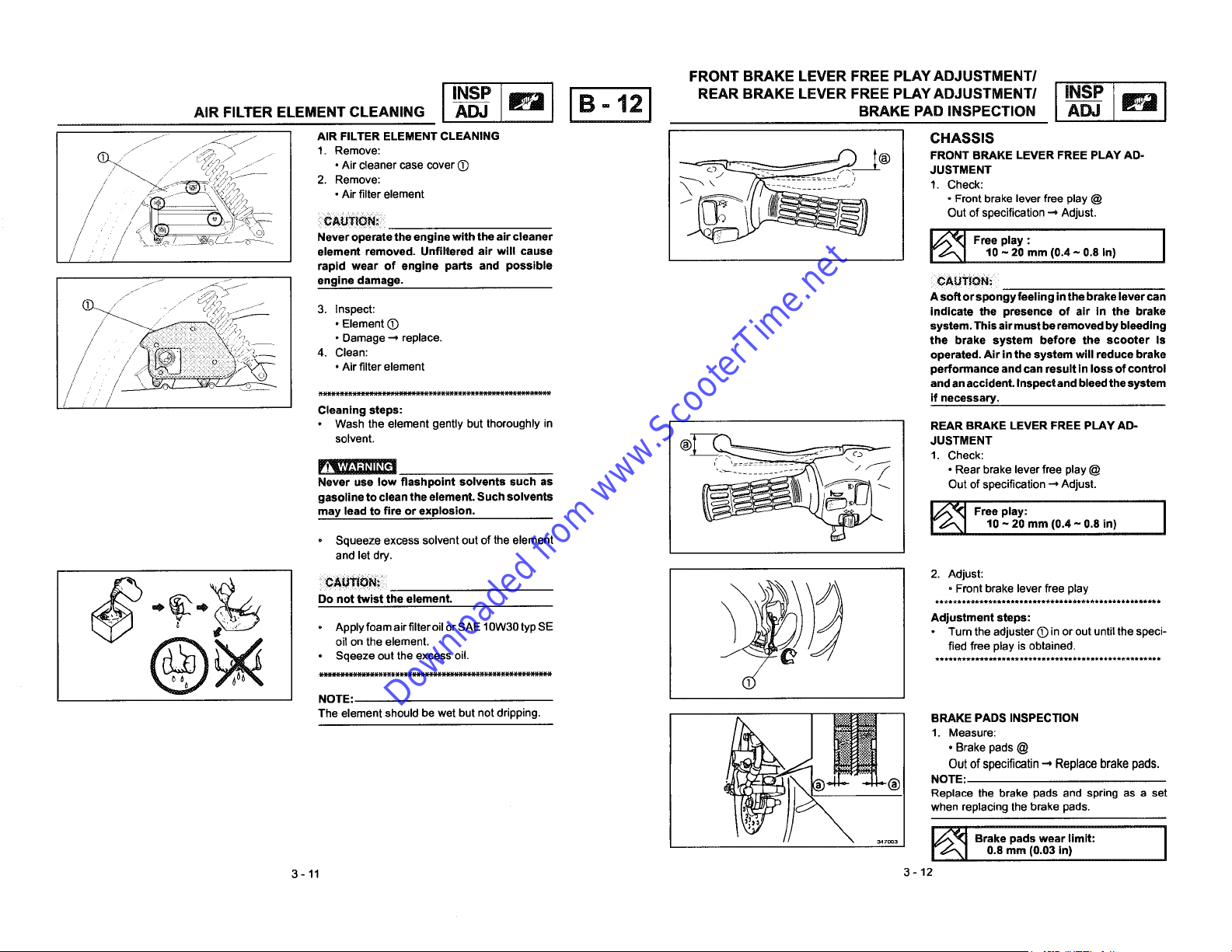
AIR FILTER ELEMENT CLEANING _ _ B - 12 BRAKE PAD INSPECTION _ _r_
-J-_ AIR FILTER ELEMENT CLEANING CHASSIS
z _ _ 1. Remove: _(_) FRONT BRAKE LEVER FREE PLAY AD-
/ 2. Remove: _ 1. Check:
/ • Air filter element • Front brake lever free play @
:CAU_i0N_:: Out of specification _ Adjust.
• Air cleaner case cover (_) _ JUSTMENT
/ element removed. Unfiltered air will cause 10 ~ 20 mm (0.4 ~ 0.8 in)
/ rapid wear of engine parts and possible
. _ J engine damage. :CAUTiONi
JJ Asoft or spongy feeling in the brake lever can
// ::=:::::::::=:::::::::::::::::=::::::=::::==:::::::"_ if necessary.
r' Cleaning steps:
Never operate the engine with the air cleaner _ Free play: I
3. Inspect: indicate the presence of air in the brake
•Element(T) system.Thisairmustberemovedbybleeding
• Damage-* replace, the brake system before the scooter Is
4. Clean: operated. Air in the system will reduce brake
• Air filter element performance and can result in loss of control
Wash the element gently but thoroughly in REAR BRAKE LEVER FREE PLAY AD-
solvent. (_)__ JUSTMENT
_l.*liW,_l;l_ll_,[Hll __=_ • Rear brake lever free play @
gasoline to clean the element. Such solvents h=,
may lead to fire or explosion. _ Free play:
Never use low flashpoint solvents such as ___ r'_'xIOutof specification --*Adjust. I
• Squeeze excess solvent out of the element
and let dry.
I II I I
and an accident. Inspect and bleed the system
1. Check:
10 ~ 20 mm (0.4 ~ 0.8 in)
....... ........ Front brake lever free play
Do not twist the element ....................................................
,_ =b Adjustment steps:
_ _ _//_ 2. Adjust:
Q_ oil on the element, fled free play is obtained.
Apply foam airfilter oil or SAE 10W30 typ SE Turn the adjuster (_) in or out until the speci-
Sqeeze out the excess oil. ,..................................................
NOTE:
The element should be wet but not dripping. /_,_ __'__ BRAKE PADSINSPECTION1..Measure:Brakepads @
3-11 3-12
Out of specificatin _ Replace brake pads.
Replace the brake pads and spring as a set
when replacing the brake pads.
_70o_ _ Brake pads wear limit:
.OTE
0.8 mm (0.03 in)
BRAKE FLUID LEVEL INSPECTION -A_ R_ B =13 AIR BLEEDING (HYDRAULIC BRAKE SYSTEM) A-_
Downloaded from www.ScooterTime.net
"E'"S"OE''"SPEC"O"'I'"SPII I I'"sp [
J
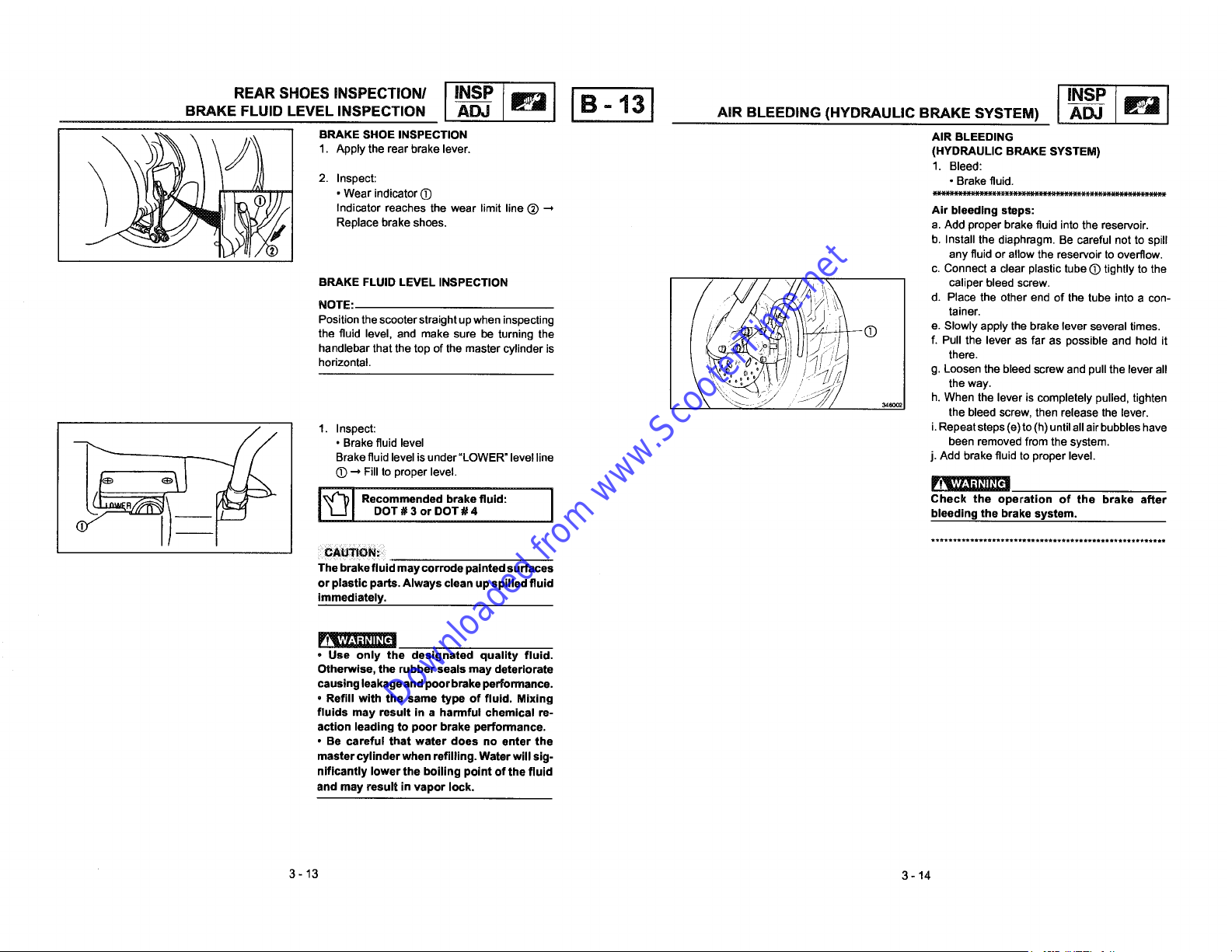
I .RAKES.OE,NSPECT.ON A,R=EEO..O
J [_ _ 1. Inspect: i. Repeat steps (e) to (h) until all air bubbles have
R __ DOT # 3 or DOT # 4 bleeding the brake system.
b/j_._ _/ _ i,_l Recommendedbrakeflu,d: I Check the operation of the brake after
// 1. pp,ytherearbra e,ever. (.YD OL,C
2. Inspect: • Brake fluid.
• Wear indicator O _=:_="_::_`"_`_`"_`"_"_-`_"_"_"_=_=_=_=_=_=_:_
Indicator reaches the wear limit line (_).-, Air bleeding steps:
Replace brake shoes, a. Add proper brake fluid into the reservoir.
BRAKE FLUID LEVEL INSPECTION _ _I\
NOTE: / , , \ d. Place the other end of the tube into a con-
the fluid level, and make sure be turning the O f. Pull the lever as far as possible and hold it
handlebar that the top of the master cylinder is there.
horizontal, g. Loosen the bleed screw and pull the lever all
Position the scooter straight up when inspecting _ e. Slowly apply the brake lever several times.
• Brake fluid level been removed from the system.
Brake fluid level is under"LOWER" levelline j. Add brake fluid to proper level.
(D "-* Fill to proper level.
/ /// //_ ' caliper bleed screw.
I_ tainer.
\ "_ -_ _ 3,6co_ h. When the lever is completely pulled, tighten
1. Bleed:
b. Install the diaphragm. Be careful not to spill
any fluid or allow the reservoir to overflow.
c. Connect a clear plastic tube O tightly to the
the way.
the bleed screw, then release the lever.
******************************************************
SYSTEM)
CAU_ioNi
The brake fluid may corrode painted surfaces
or plastic parts. Always clean up spilled fluid
immediately.
_lvAvL,l;I_11_[rll
• Use only the designated quality fluid.
Otherwise, the rubber seals may deteriorate
causing leakage and poor brake performance.
• Refill with the same type of fluid. Mixing
fluids may result in a harmful chemical re-
action leading to poor brake performance.
• Be careful that water does no enter the
master cylinder when refilling. Water will sig-
niflcantly lower the boiling point of the fluid
and may result in vapor lock.
3-13 3-14

I'"sPI I'"sp I
Downloaded from www.ScooterTime.net
1. Check: Proper loading of your scooter is Important
• Steering assembly bearings for the handling, braking, and other perform-
Grasp thebottom ofthe forks andgently rock ance and safety characteristics of your
the fork assembly back andforth, scooter. Do not carry loosely packed Items
Looseness _ Adjust steering head. that can shift.
*************************************************** Securely pack your heaviest items close to
Steering head adjustment steps: the center of the scooter, and distribute the
STEERING HEAD ADJUSTMENT VT_W_,_I-I_.II_,[¢!
Remove thefront fender and the front panel, weight evenly from side to side. And check
Refer to "COVERS" section, the condition and pressure of your tires.
, Tighten the nut (D Makesurethetotalweightofthecargo, rider,
C)__ Ref : 90890-01268 saddlebags, etc. If approved for this model)
/
_._/ _ Unscrew the securing nut I NEVER OVERLOAD YOUR SCOOTER.
I_=_ Steering headwrench: passenger, and accessories (fairing,
NOTE: could cause tire damage, an accident, or
Tighten the ring nut until no play can be seen. even injury.
I_ I Securing nut: 'I 15psi) 18psi)
NOTE: 15psi) 21 psi)
Set the torque wrench (_)tothe ring nut wrench Maximumload: 152kg(335Ib)
SOthat they form a right angle.
***************************************************** wheel.
TIRE INSPECTION Ride conservatively after installing a tire to
1. Measure:.Air pressure allow it to seat itself properly on the rim.
Ref:90890-01403 doesnotexceedthe maximumloadofthe
Install the securing nut _re pressure(oald) Front Rear
Tighten the securing nut (_ Upto 90kg 100kPa 125kPa
22.5 Nm (2.25 m.kg, 16.2ft.lb) 90 kg- maximum 100kPa 150kPa
Move the handlebar up and down, and / or
back and forth. If the handlebar free play is
torque. _.'="_i' WearlDamagelCrackslRoad hazards-_ Re-
Handlebarsecuringbolt: , .
60 Nm (6.0m.kg, 43.4 ft.lb) • Wheels
Instal the front panel and front fender. Never attempt even small repairs to the
excess, tighten the bolt (_)to the specifiedI _'_'___'i'_" 2. Inspect:
Out of specification _ Adjust, • Ifthe tire is removed with a tire lever, use a
//j/_ ".//).; Damage/Bends --_Replace.
scooter. Operation of an overloaded scooter
load* (1.0Okgflcm_, (1.50kgflcmz,
• Maximumloadisthetotalweightof cargo,rider,pas-
sengerandaccessories.
• Tire surface
(1.00kgf/cm=, (1.25kgflcm',
Fv_
suitable protection to prevent damaging the
rim.
• When installing the tire, make sure the
arrow points to the front.
3-15 3-16
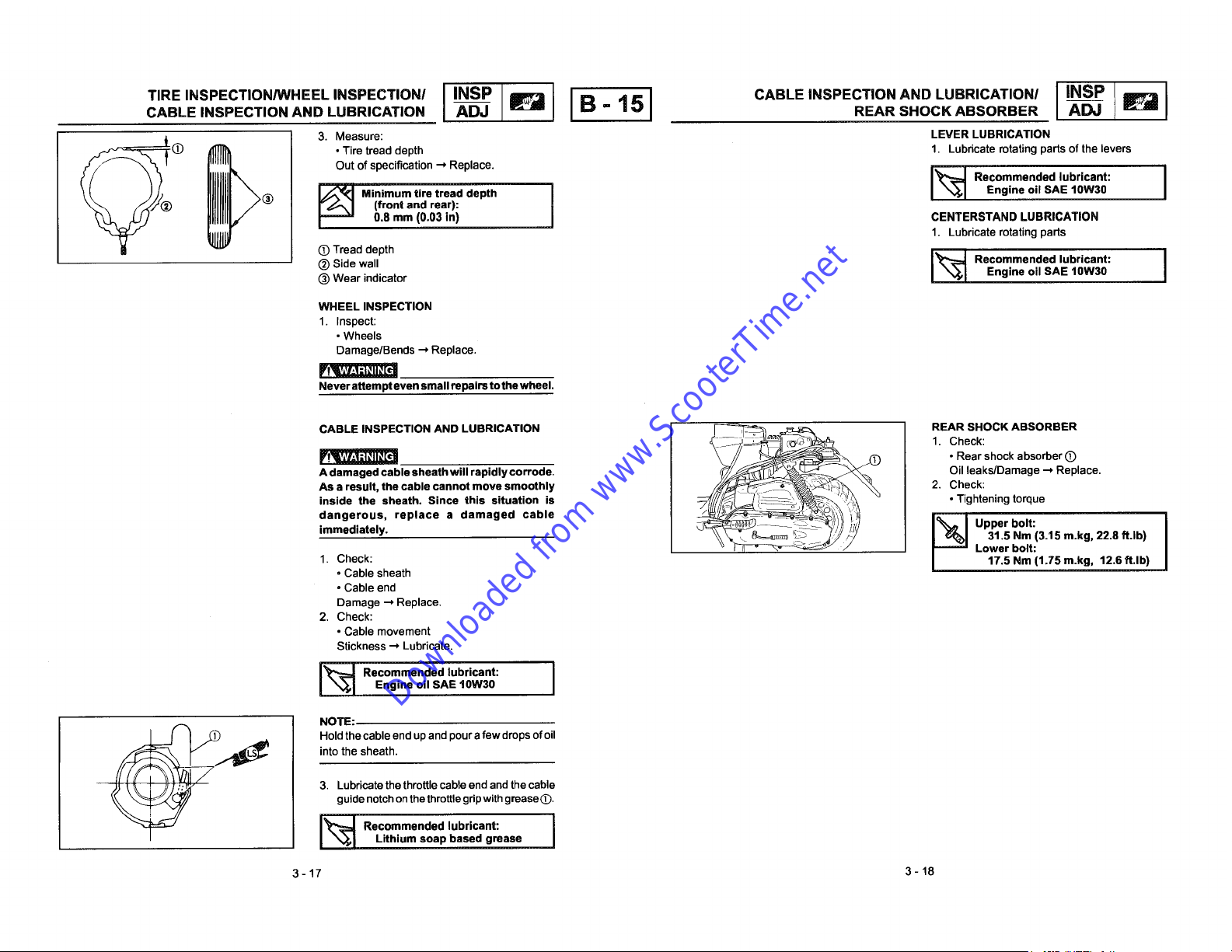
CABLE INSPECTION AND LUBRICATION _ _ B - 15 REAR SHOCK ABSORBER _
Downloaded from www.ScooterTime.net
TIRE INSPECTION/WHEEL INSPECTION/ I INSP I I I CABLE INSPECTION AND LUBRICATION/ I INSP I
I:_ • Tire tread depth 1. Lubricate rotating parts of the levers
Out of specification ._ Replace.
Recommended lubricant:
(_ (front and rear):
I_ Minimum tire tread depth Engine oil SAE 10W30
I 0.8 mm (0.03 in) CENTERSTAND LUBRICATION
(D Tread depth
esr ivuco
(_)Side wall I_=_ Rec°mmended lubricant: I
® Wear indicator Engine oil SAE 10W30
WHEEL INSPECTION
1. Inspect:
• Wheels
Damage/Bends _ Replace.
Fv_
Never attempt even small repairs tothe wheel.
CABLE INSPECTION AND LUBRICATION F'==_=_ .___ REAR SHOCK ABSORBER
VIIYL, I-'I_II_.[tt • Rear shock absorber (D
Adamaged cable sheath will rapidly corrode. Oil leaks/Damage _ Replace.
As a result, the cable cannot move smoothly 2. Check:
inside the sheath. Since this situation is • Tightening torque
immediately. 31.5 Nm (3.t 5 m.kg, 22.8 ft.lb)
dangerous, replace a damaged cable Upper bolt:
1.
Check:
• Cable sheath
° Cable end
Damage --*Replace.
2. Check:
• Cable movement
Stickness --*Lubricate.
1. Lubricate rotating parts
1. Check:
Lower bolt:
I
I 17.5 Nm (1.75 m.kg, 12.6 ff.lb)
|
I_ Recommended lubricant:
NOTE:
into the sheath.
_._ Hold thecable end up and pour afew drops ofoil
,,: 3. Lubricate the throttle cable end and thecable
I_:_ Recommended lubricant:
3-17 3-18
Engine oil SAE lOW30
guide notch onthe throttle grip with grease (D.
Lithium soap based grease

BATTERY INSPECTION ADJ _ B- 1 6 FUSE INSPECTION _
Downloaded from www.ScooterTime.net
IINSPII I BATTERYINSPECTIONIIINSP I
I_ I t_ _'_ /_) BATI'ERY INSPECTION
LOWER • Batteryfluidlevel ittoensuremaximumperformance.
-- UPPER -__ 1. Inspect: Always charge a new battery before using
ELECTRICAL :CAgTiONi
Fluid level low --_Add to proper level. _IW:I--I_JI_[_
Fluid level should be between upper and
lower level marks. Battery electrolyte is dangerous. It contains
_) Upper level sulfuric acid which is poisonous and highly
Lowerlevel Alwaysfollowthesepreventivemeasures:
Refill with distilled water only. Tap water can cause severe burns and permanent
contains minerals which are harmful to a eye injury.
battery. • Wear protective eye gear when handling
2. Inspect: • Drink large quantities of water or milk.
• Breather hose Followwith milkof magnesia, beaten egg,
Obstruction _ Remove. or vegetable oil. Get immediate medical
3. Inspect: attention.
• Battery
........................................................ Charge batteries in awell-ventilated area.
Replace the battery if: ° Keep batteries away from fire, sparks, or
Batteryvoltagewillnotrisetoaspecificvalue open flames (e.g., welding equipment,
or bubbles fail to rise during charging, lighted cigarettes, etc.)
Sulfation of one or more cells occurs. (As ° DO NOT SMOKE when charging or han-
indicated by the plates turning white, or an dling batteries.
accumulation ofmaterial in the bottom of the KEEP BATTERIES AND ELECTROLYTE OUT
sell.) OFREACHOFCHILDREN.
Specific gravity readings after a long, slow
charge indicate that onecell is lowerthan the
rest.
Warpage or buckling of plates or insulators is
evident.
*******--***--*********************--*********
caustic.
• Avoid bodily contact with electrolyte as it
or working near batteries.
Antidote (EXTERNAL) :
- SKIN- Flush with water.
• EYES - Flush with water for 15 minutes
and get immediate medical attention.
Antidote (INTERNAL) :
Batteries generate explosive hydrogen gas.
Always follow these preventive measures:
• Specific gravity 1. Open the seat.
Less than 1.280 .-_Recharge battery. 2. Inspect:
_1 Charging Current: Blown --, Replace,
i Specific Gravity:
3- 19 3-20
0.4 amps/10 hrs
1.280 at 20°C (68° F)
• Fuse
 Loading...