

Page 1
Doc. No. HRS 017U-04
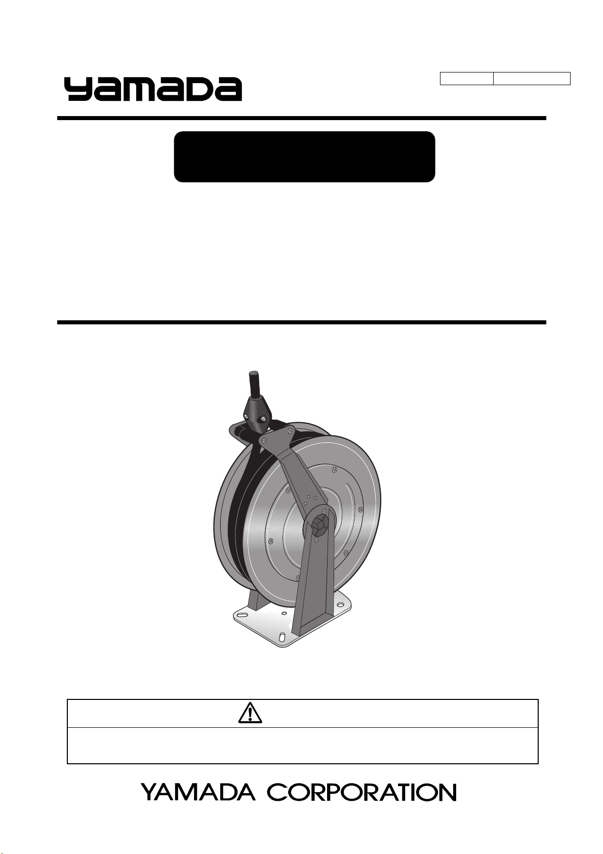
INSTRUCTION
HOSE REEL(HR Series)
HR- 3G10 MODELNo. N831488
HR- 3C15 MODELNo. N832888
HR- 3WH15 MODELNo. N831888
HR- 4A15 MODELNo. 854671
HR- 4G15 MODELNo. N831689
HR- 4W15 MODELNo. N830889
WARNING
Prior to operating this product, be sure to read this operation manual for safety. After reading the manual, please
keep it on hand for future reference.
Page 2
- Preface
Thank you for purchasing a Yamada product. HR series Hose Reels are spring-driven and ceiling-, wall-, or floor
mounted hose reels used to supply air, oil, grease, water, and warm water at various sites such as maintenance
factory or gas station.
Built-in ratchet mechanism locks the reel at desired hose length. You can wind up the supply hose onto the reel drum
by drawing it a little further so that it will not get in the way when not in use.
- For Safe Operation
This manual describes the items that are important for the user to operate this product safely, correctly, and efficiently.
Before operating this product, read this manual thoroughly, in particular, “Warnings and Cautions” at the beginning of
this manual.
- Warnings and Cautions
For safe use of this product, be sure to note the following: In this document, warnings and cautions are indicated by
symbols. These symbols are for those who will operate this product and for those who will be nearby, for safe
operation and for prevention of personal injury and property damage. The following warning and caution symbols
have the meanings described below. Be sure to remember their meanings.
WARNING :
This indicates the existence of potential hazard which, if not avoided, will
result in death or serious injury.
1/2
CAUTION :
Furthermore, to indicate the type of danger and damage, the following symbols are also used along with those
mentioned above:
This symbol indicates a DON'T, and will be accompanied by an explanation on something you must not
do.
This symbol indicates a DO, and will be accompanied by instructions on something you must do in a
certain situation.
This indicates the existence of potential hazard which, if not avoided, may
result in bodily injury or in physical damage.
- Precautions on Use
The following warnings and cautions are very important. Be sure to observe them.
WARNING
- Never make modifications to the product. Unauthorized modifications could result in physical injury and
accidents, as well as degraded functionality.
- Do not use with gasoline, kerosene, or other solvents. It can cause severe injury, property damage, or
product malfunction.
- If the service hose has difficulty rewinding, request services from your dealer. Reckless disassembly
could cause the powerful spiral spring to eject, causing serious physical injury.
- Some oils and greases can cause skin inflammation.
Thoroughly read the handling precautions for oil and grease provided by a supplier before use.
- When rewinding the service hose, do not release it at once. The gun attached to the hose end could
violently swing to left and right when the hose rolls up, resulting in property damage or physical harm.
Handle the service hose with maximum care.
- HR series hose reels have a specified allowable fluid temperature and maximum working pressure.
Using the hose reel beyond the specifications may wear out packings and hoses. Any secondary
accidents such as body injury or facility contamination caused by ignoring the instructions are the user’s
responsibility.
Page 3
2/2
WARNING
- Do not pull the supply hose forcibly or bend it tightly. Improper handling may damage the hose or
decrease the capacity of the hose pressure. Any secondary accidents such as body injury or facility
contamination caused by ignoring the instructions are the user’s responsibility.
- To prevent a fall, wear a safety harness while installing the hose reel in a high place. For your safety,
keep your work space clear.
- When installing the hose reel in a ceiling, firmly fasten it so that it will never fall down. Inadequate
installation can cause the hose reel to fall down, resulting in a serious accident.
CAUTION
- When the supply hose is completely pulled out, do NOT pull any further. If you keep pulling it out, it may
result in damage to the spring and supply hose or cause product malfunction.
- Do not pull out or wind up the supply hose vigorously. Rough handling may affect the function of each
part or cause malfunction in the hose reel or damage to the hose.
- Conduct pre-use inspection. If the hose is damaged or defective or if the hose reel doesn’t work
normally, immediately stop using, turn off a supply source, release the residual pressure in the hose,
and contact your distributor for service.
- Adjustment of the hose-stop must be done when the hose is latched. The supply hose, if not secured,
may wound onto the drum unexpectedly, resulting in facial injury.
- At the end of each day's work, in the nighttime or on holidays, cut off air supply and vent the hose. A
hose left under pressure without cutting off air supply could damage the hose and packing, resulting in
material leaks to contaminate your plant facilities. Such secondary disasters are the user's
responsibility.
- You may burn your hand by friction if you allow the hose to retract vigorously, holding it.
- If the warning/caution labels are damaged or peeled off, purchase them from our distributor and attach
properly.
- The supply hose may be damaged if pulled to the side. Use Pivoting wall bracket (optional extra:
N372407, N372408) if you want to pull the hose to the side.
- Maintain the ambient temperature within -10 to 60℃.
- If source pressure is greater than specified, set it to the specified value.
- In the use of air, maintain air pressure of 1.5MPa or less. Exceeding this limit may affect the function of
each part or cause product malfunction.
- In the use of water, maintain water pressure of 1.5MPa or less. Exceeding this limit may affect the
function of each part or cause product malfunction.
- In the use of oil, maintain operating pressure of 7.5MPa or less. Exceeding this limit may affect the
function of each part or cause product malfunction.
- In the use of grease, maintain operating pressure of 35MPa or less. Exceeding this limit may affect the
function of each part or cause product malfunction.
- In the use of warm water, maintain water pressure of 25MPa or less for water at 50 degree Celsius and
10MPa for water at 150 degree Celsius. Exceeding these limits may affect the function of each part or
cause product malfunction.
- When deciding installation site, avoid any place where it will be subjected to direct sunlight or near
chemicals. Also, be careful about heat radiation. The lifetime of the hose reel can be reduced by such
factors.
Page 4

Table of Contents
- Preface
- For Safe Operation
- Warnings and Cautions
- Precautions on Use
1. Names of Parts
1.1 Names of Parts .................................................................................................................... 1
1.2 Contents of Package ........................................................................................................... 1
2. Mounting
2.1 Mounting examples and mounting instruction ...................................................................... 2
2.2 Hose Outlet (Arm angle adjustment) .................................................................................... 3
2.3 Connection to the pipework system ..................................................................................... 4
3. Operation
3.1 Installation of Dispensing Tool ............................................................................................. 5
3.2 Positioning of Hose-Stop ..................................................................................................... 5
3.3 Adjustment of Spring Tension .............................................................................................. 5
4. Maintenance and Inspection
4.1 Troubleshooting ................................................................................................................... 6
4.2 Maintenance and Inspection ................................................................................................ 6
4.3 Replacement of Consumables and Repair .......................................................................... 6
5. Parts Disassembly Drawing and Parts List ..................................................................... 7
6. Specifications
7. Limited Warranty
.......................................................................................................................... 8
.................................................................................................................... 10
Page 5

1. Names of Parts
1.1 Names of Parts
1.2 Contents of Package
Fig.1 Names of Parts
■Contents of a package
As soon as you open the box, inspect the product for damage and check that all the accessories are included.
The mounting template is printed on the lid of the box.
■Label
As shown below, there is a type label attached on the reel. Check the maximum working pressure of your reel.
Max. working
Max. w o rki n g
pressure
(MPa)
1.5
7.5
35
pressure
(MPa)
10
25
Water Air Oil Grease
●●
●
Warm Water
50°C 150°C
●
●
1
●
Page 6

2. Mounting
2.1 Mounting examples and mounting instruction
The reel can be wall-, floor-, or ceiling mounted according to Fig.2.
Mounting bracket (Fig.3, Part# 801951) and Mounting rail (Fig.7,
Part# 704439 – 704442, 715723, 716723) are recommended for easy
installation. (Sold separately)
<Note>
Especially when you are going to install two or more reels, these
optional extras are strongly recommended to arrange the reels
neatly.
If you want to pull the hose to the side, Pivoting wall bracket (Fig.4,
Part# N372407, N372408) is also available.
1) Maximum installation height above floor level is 4m.
2) Select a level surface on which to mount the reel.
3) Make sure to use suitable fixing bolts that can tighten the reel
securely.
4) When mounting the reel directly, use the template on the lid of the
packing box to mark the mounting holes. (Fig.5)
5) When using a mounting bracket or mounting rail for installation,
follow the following procedures and refer to Fig.6.
a. Place an anchor bolt or construct a mounting hole at the
mounting position to meet the mounting rail mounting hole.
b. Clamp the mounting rail at the mounting position with a nut or
bolt.
c. Secure the clamping plate for the mounting bracket to the
mounting rail with four bolts and nuts for each unit.
d. Mount the mounting plate at the hose reel mounting holes with
four bolts.
e. With one clamping plate of the clamping bar removed (the
other slightly loose), insert the upper part of the mounting plate
mounted on the reel into the clamping plate.
f. Attach the clamping bar and tighten both bolts to clamp the
reel.
Fig.3
Fig.2
Fig.4
Fig.5
WARNING
- In constructing the mounting position, ensure that the
anchor bolts, mounting holes and so forth have sufficient
strength to safely withstand the force that is exerted by
the service hole as it is pulled. An insufficient mounting
strength could result in a fall accident, causing death or
serious physical harm to the user.
Fig.6
2
Page 7

2.2 Hose Outlet (Arm angle adjustment)
Fig.7 Mounting rail
The hose outlet can be fitted in your desired position by rotating the
arm 36 degrees at a time. (Fig.8)
Choose the position where the hose is bent as little as possible.
1) Remove the lock head from one side using the provided tool (Torx
driver T25). (Fig.9)
2) Remove the other side of the lock head. (Fig.10)
3) Loosen the four screws a little (1/2 revolution). (Fig.11)
4) Find a desired angle by rotating the arm 36 degrees at a time.
(Fig.12)
5) Tighten the four screws securely in the desired position.
6) Attach the lock heads to both sides.
CAUTION
- Do not remove the four screws, just loosen them.
Do not loosen these
two screws.
Fig.9
②
③
Fig.11
Fig.8
Fig.10
①
④
Fig.12
3
Page 8

2.3 Connection to the pipework system (Fig.13)
Install a stop valve on the pipe system before connecting the hose.
1) Attach the ring on the arm. (Fig.13)
2) Pass the intake hose through the ring and connect it to the pipe
work.
Use the provided hose fitting if necessary. (See Table 1)
3) Check that the intake hose is not twisted or strained after
connection.
■Tab l e 1
Product No. Description Model Application
N831488 HR-3G10 Oil
N832888 HR-3C15 Grease
N831888 HR-3WH15 Warm Water 3/8 × 1m G3/8 685919 Male fitting G3/8- R3/8
854671 HR-4A15 Air
N830889 HR-4W15 Water
N831689 HR-4G15 Oil
Hose Reel
888
Hose Reel
889
Ho s e Size Outlet
1/2 × 1m G1/2 686455 Male fitting G1/2- R3/8
3/8 × 1m
1/2 × 1m R1/2 686452 Union Adapter Rc1/2 - G1/2
1/2 × 1m R1/2 686454 Male fitting G1/2 - R1/2
1/2 × 1m G1/2 681785 Male fitting G1/2 - R1/2
G3/8
Intake Ho s e
Fitting (access ory)
Part No. De s cription Size
680140 Male fitting G3/8- R3/8
684517 Male fitting G3/8- G1/4
Fig.13
3. Operation
The hose reel is delivered with a ratchet mechanism which retains the
hose in the required outdrawn position. (Fig.14)
The ratchet will disengage if the hose is drawn out a little further and the
hose then recoils to the drum. It should be noted that the hose should be
held by the hand as long as possible during the recoiling.
CAUTION
- When pulling out the supply hose, always hold the hose and pull it out straight. The hose may be
damaged if excessive force is applied to the hose fittings.
- Do not let go of the hose when rewinding to prevent it from being wound vigorously onto the drum.
- You may burn your hand by friction if you allow the hose to retract vigorously, holding it.
- Use Pivoting wall bracket (optional extra: N372407, N372408) if you want to pull the hose to the side.
- Do not pull out or wind up the supply hose vigorously. Rough handling may affect the function of each
part or cause product malfunction or damage to the hose.
Fig.14 ratchet mechanism
4
Page 9

3.1 Installation of Dispensing Tool
Attach the provided hose fitting to the hose end. Then, attach a dispensing tool such as a gun to the hose fitting.
(Refer to Table 2)
■Tab l e 2
Product No. Description Model Application
N831488
N832888 HR-3C15 Grease
N831888
854671
N830889
N831689
Hose Reel
888
Hose Reel
889
HR-3G10 Oil
HR-3 WH15 Warm Wa ter 3/8 × 15m G3/8
HR-4A15 Air
HR-4W15 Water
HR-4G15 Oil
Hos e Size Outlet
3/8 × 10m G3/8 680140 Male fitting G3/8- R3/8
3/8 × 15m G3/8
1/2 × 15m Rc1/2
1/2 × 15m R1/2 686457 Socket Rc1/2 - Rc1/2
1/2 × 15m G1/2 681785 Male fitting G1/2 - R1/2
Supply Hose
Fitting (access o ry)
Part No. Description Size
680140 Male fitting G3/8- R3/8
684517 Male fitting G3/8- G1/4
3.2 Positioning of Hose-Stop
Pull out the hose to the proper length and latch it. Remove the
hose-stop from the hose and install it securely to the desired position.
(Fig.15)
CAUTION
- If the hose-stop is not properly attached to the hose, it
may move when it hits against the outlet.
3.3 Adjustment of Spring Tension
1) With the supply hose completed coiled, insert a square drive
(13mm) into the square hole in the spring hub. (Fig.16)
2) Holding the square drive tightly in your hand, remove the two
screws securing the spring hub by using the provided tool (Torx
driver T25).
3) To increase spring tension, turn the spring hub to the A direction
(counterclockwise).
To decrease spring tension, turn the spring hub to the B direction
(clockwise).
4) Secure the spring hub with the two screws, holding the square
drive tightly.
5) After adjustment, check that the required length of the hose can
be drawn out without stretching the spring to the limit.
Fig.15
Fig.16
CAUTION
- Wear safety gloves when adjusting spring tension. There is a risk of injury.
- Failure to use the right tool for the square hole in the spring hub may result in an unexpected injury.
- Once the two screws are removed, spring tension is applied to the square wrench. Hold the wrench
tightly during adjustment.
5
Page 10

4. Maintenance and Inspection
4.1 Troubleshooting
Reel cannot be locked. Hose-stop or spring is damaged. Contact for service.
Supply hose doesn’t recoil
even after ratchet is
disengaged.
Discharge decreases or
completely stops .
Leak occurs at joint. Gasket in swivel is worn out. Contact for service.
Problem Possible Cause Remedy
Hose is wound unevenly and stuck somewhere.
Supply hose is clogged or damaged. Clean supply hose or replace it.
Pull out s upply hos e com pletely and
rewind it.
4.2 Maintenance and Inspection
The following maintenance is recommended to be accomplished regularly at least once a year.
Hoses and each moving part are consumables. Inspect them periodically and if they are damaged or worn out,
contact our distributor or service shop for early replacement.
1) Check the spring function by testing if the supply hose recoils properly.
2) Check the swivel and hose couplings for leak by sight or hand. Change the gasket if necessary.
3) Check the hose for damage by sight or hand. Clean the hose if it is oiled or dirty.
4) Check the ratchet mechanism and inspect the ratchet (pawl) for damage.
5) Check the mounting of the reel on wall or ceiling.
4.3 Replacement of Consumables and Repair
Contact our distributor or service shop for replacement of consumables or repair.
To replace the supply hose, follow the following instructions.
■Preparation for Replacement
1) Turn off the supply of air/water/oil/grease/warm water. Then, remove residual pressure in the hose.
2) Wind up the hose completely onto the drum and neutralize the spring tension according to [3.3 Adjustment of
spring tension].
3) Remove the hose-stop and any other devices such as a gun from the supply hose.
■Replacement of Supply Hose
1) Let the hose end pass through the outlet and disconnect the hose from the drum swivel.
2) Pass a new supply hose through the outlet and attach it to the drum swivel.
3) Attach the hose-stop to the new hose, adjusting its position.
4) Remove the two screws securing the spring hub.
5) Insert a square wrench (13mm) into the square hole in the spring hub. (Fig.16)
6) Turn the wrench to the A direction (counterclockwise) to wind up the supply hose.
7) Once the hose is completely wound onto the drum, adjust spring tension by turning the wrench to the A direction
(counterclockwise).
8) Secure the spring hub with the two screws, holding the square drive tightly.
9) After adjustment, check that the required length of the hose can be drawn out without stretching the spring to the
limit.
<Note>
When replacing the service hose and inlet hose for air hose reels, please tighten the each hose band by 3N-m and
5N-m of torque.
6
Page 11

CAUTION
- Wear safety gloves when adjusting spring tension. There is a risk of injury.
- Failure to use the right tool for the square hole in the spring hub may result in an unexpected injury.
- Once the two screws are removed, spring tension is applied to the square wrench. Hold the wrench
tightly during adjustment.
5. Parts Disassembly Drawing and Parts List
No.
10 N372415 N373158 N372415 N376331 Spring 1
11 N372419 Spring hub 1
※
N831488 N832888 N831888 854671 N830889 N831689
HR-3G10 HR-3C15 HR-3WH15 HR-4A15 HR-4W15 HR-4G15
1 N344854 N376280 N344852 N372457 N376585 N344854 Intake hose 1
2 N343708 N345628 N344984 N342422 N343708 Swivel 1
3 N361982 N361983 N332581 N361982 Gasket 1
4 N376278 Bearing 1
5 N372433 Cam 1
6 N372418 Ratchet 1
7 N371467 Outlet 1
8 N343541 N343851 N341342
9 N376330 N376279 N371539 804992 N374121 N372439 Supply hose 1
No.8 hose stopper 770199,619155,627012,711030 only two Q'ty
Part No.
※770199
619155
627012
711030
Description Q'ty
N343540 Hose stop
7
1
(2)
Page 12

6. Specifications
■Specifications
Intake
hose
Supply
hose
Operating Temp. of Hose [℃] -40 to 155
Max. Working Pressure [MPa]
Intake
hose
Supply
hose
Operating Temp. of Hose [℃] -30 to 100
Max. Working Pressure [MPa] 1.5
Product No.
Description
Mod el
Application Warm Water
Weight [kg] 13.8
Hose size
Fitting
(acces s ory)
Hose size
Fitting
(acces s ory)
Am bient Temp. [
Product No. N830889
Description
Mod el
Application Water
Weight [kg] 13.7
Hose size
Fitting
(acces s ory)
Hose size
Fitting
(acces s ory)
Am bient Temp. [℃]
N831488
HR-3G10
Oil
12.1
1/2 × 1m
Outlet G3/8
Part No. 686455 680140 684517
Description Male fitting Male fitting Male fitting
Size G1/2 - R3/8 G3/8 - R3/8 G3/8 - G1/4
Outlet G3/8
Part No. 680140 680140 684517
Description Male fitting Male fitting Male fitting
Size G3/8 - R3/8 G3/8 - R3/8 G3/8 - G1/4
]
℃
Outlet
Part No. 686452 686454 686452 686454 681785
Description Union Adapter Male fitting Union Adapter Male fitting Male fitting
Size Rc1/2 - G1 /2 G1/2 - R 1/2 Rc1/2 - G1/2 G1/2 - R1/2 G1/2 - R1/2
Outlet R1/2
Part No. 681785
Description Male fitting
Size G1/2 - R1/2
G1/2
3/8 × 10m
G3/8
-40 to 100
7.5 25(50℃)10(150℃)
854671
HR-4A15
Ai r
11.2
1/2 × 1m
R1/2
1/2 × 15m
R1/2
686457
Socket
Rc1/2 - Rc1/2
-20 to 60
1.5
N832888
Hose Reel 888
HR-3C15
Greas e
16.9
3/8 × 1m
3/8 × 15m
G3/8
-40 to 100
35
-10 to 60
Hose Reel 889
-10 to 60
HR-4W15
1/2 × 1m
R1/2
1/2 × 15m
686457
Socket
Rc1/2 - Rc1/2
N831888
HR-3WH15
3/8 × 1m
G3/8
685919
Male fitti ng
G3/8 - R3 /8
3/8 × 15m
HR-4G15
-40 to 100
N831689
1/2 × 15m
Oil
16.3
1/2 × 1m
G1/2
G1/2
7.5
8
Page 13

■Dimensions
N831488, N831888 [ ]: for 854670
N831689,[ ]: for N830889, 854671
9
Page 14

7. Limited Warranty
● If an abnormality occurs during normal operation in accordance with the operating instructions and other operating
cautions within the warranty period (12 months after date of purchase) that can be attributed to a manufacturing
defect, the defective parts of this product will be serviced or the product will be replaced free of charge. However,
this warranty will not cover compensation for incidental damage or any malfunction listed below.
1. Warranty period
This warranty will be valid for a period of 12 months after the date of purchase.
2. Warranty
If, during the warranty period, any of the material of the genuine parts of this product or the workmanship of this
product is found defective, and is so verified by our company, the servicing cost will be fully born by our company.
3. Exclusion
Even during the warranty period, this warranty does not cover the following:
1) Malfunction arising from use of parts other than manufacturer-specified genuine parts
2) Malfunction arising from misuse or operating errors, or lack of storage or maintenance care
3) Malfunction arising from use with a fluid that may cause corrosion, inflation or dissolution of the component
parts of the product
4) Irregularity arising from repair made by other than by our firm, our regional office, dealer or authorized service
personnel
5) Malfunction arising from modification of the product by other than authorized service personnel
6) Wear and tear of parts that must be regularly replaced in the course of normal operation, such as packings,
O-rings, balls, and valve seats
7) Malfunction and/or damage due to transportation, moving or droppage of the product after purchase
8) Malfunction and/or damage due to fire, earthquake, flood or other force majeure
9) Malfunction arising from use of compressed air that contains impurities or excessive moisture, or use of
gases or fluids other than the specified compressed air
10) Malfunction arising from use with a fluid that causes excessive abrasion or use of lubricating oil other than
that specified for this product
Furthermore, this warranty does not cover the rubber parts, or other parts that are subject to wear in normal
operation, used in this product and its accessories.
4. Parts
Parts for this product will be kept available for 5 years after discontinuation of production. Once 5 years have
elapsed after close of production, availability of parts for this product cannot be guaranteed.
10
Page 15

MEMO.
Page 16

Manufactured by
YAMADA
CORPORATION
INTERNATIONAL DEPARTMENT
1-1-3 Minami Magome, Ohta-ku, Tokyo 143-8504, Japan
PHONE : +81-(0)3-3777-0241
FAX : +81-(0)3-3777-0584
201306 HRS017U
 Loading...