

Page 1
Doc. No. OSA037U-03
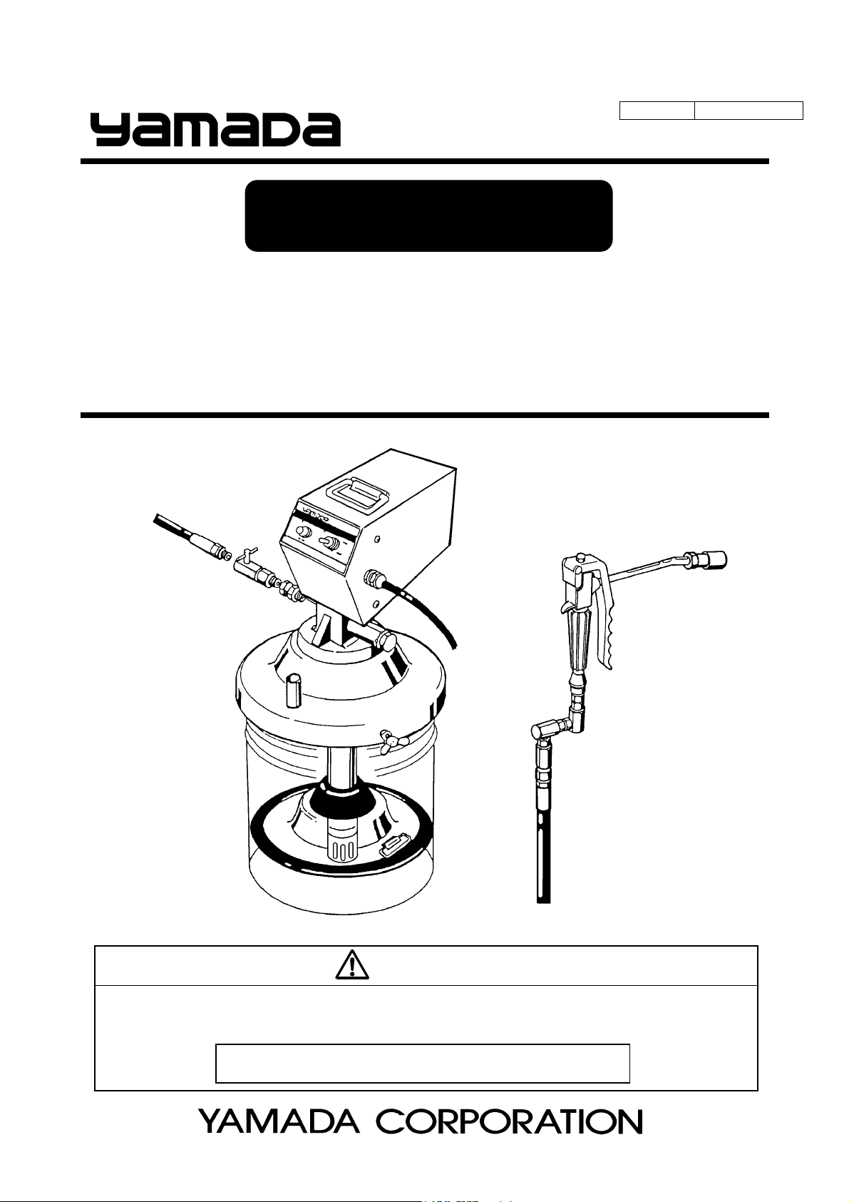
INSTRUCTION
ELECTRIC GREASE LUBRICATOR
( AC-100V 50/60Hz )
EPL-100 MODEL No.880899
WARNING
Prior to operating this pump, be sure to read this operation manual for safety. After reading the manual, please
keep it at hand any time for your quick reference.
The power supply cannot be used other than AC100V.
Page 2
- Preface
Thank you very much for purchasing Yamada Pump. This machine is a portable type lubricator that is indispensable
for grease lubrication for machines and vehicles. The pump is driven by AC-100V ( 50/60Hz ).
This lubricator cannot be used for oil lubrication. The applicable grease is limited to a type of NLGI No.2 or less in
the normal operating conditions. If the lubricator is used in an extremely cold or low-temperature environment, the
discharge volume will be remarkably lowered. Silicone grease is not applicable.
- For Safe Operation
This document describes the items that are important for the user to operate this product safety, correctly, and
efficiently. Before operating this product, read this manual thoroughly, in particular, “Warnings and Cautions” at the
beginning of this manual, with a good understanding of its contents. Keep this manual carefully in an easy-to-access
place so that the user may refer to it whenever necessary.
- Warnings and Cautions
To use this product safely, be sure to observe the contents of the following description. In this manual, warnings and
cautions are indicated by using symbols. These symbols are intended to prevent death or serious injury that may be
caused to the operator or those who are around the product and damage that may be caused to the articles that are
around the product, as well as to use the product safely and correctly. Each symbol is indicated and has a meaning
as shown below. Read the description with a good understanding of its contents.
WARNING :
This indicates the existence of potential hazard which, if not avoided, will
result in death or serious injury.
1/2
CAUTION :
To indicate the contents of danger and damage, the following symbols are used together with the above indications.
This symbol indicates an act that is prohibited (prohibition). The concrete contents of prohibition are
indicated by the side of the indication.
This symbol indicates the contents that must be observed. The concrete contents of observance are
indicated by the side of the indication.
This indicates the existence of potential hazard which, if not avoided, may
result in bodily injury or in physical damage.
Page 3
- Precautions on Use
The following warnings and cautions are very important. Be sure to observe them.
- Gasoline is a high-volatility material. Do not use gasoline to clean the pump in any case, otherwise it
may cause ignition or explosion.
- Remodeling this machine may result in a bodily accident or failure. Do not remodel the machine in any
case, otherwise it will invite danger.
- The material to be discharged from this machine may become a hazardous object depending on its
nature. Be sure to discharge it in a vessel. Do not discharge it directly on the ground.
- This machine users aluminum alloy for the liquid contact section of machine and NBR for the seal
section, respectively. Any solvent or chemical which corrode these materials is not available.
If used, corrosion could lead to a liquid leak, resulting in damages on the human body or properties.
- If the material handled come into direct contact with or is splashed over your body, it could be harmful
to the eye or skin. Be sure to check the material handled, and when you work with it, put on a
protective gear (protective mask, glasses, safety gloves, etc.) depending on the degree of danger.
2/2
WARNING
- Some types of grease may contain a carcinogenic material. Read the cautions for handling grease
given by the grease maker carefully when handling the grease.
CAUTION
- Do not operate the gun lever with the discharge port facing to another person during machine operation
in any case. A direct hit against the human body may result in an accident such as skin damage.
- The operator or administrator of this pump should not allow those who have no knowledge of the pump
to operate it.
- Silicone grease is not applicable to this pump. It may cause extremely short lifetime of the pump or
pump damage.
- After the end of daily work, at night, and on holidays, be sure to shut off the power air to this machine to
release the gun so as to bleed the internal pressure. Any secondary accident such as pollution of
installation, due to pump operation driven by worn-away packing or hose without shutting off the supply
air, shall be attributable to the user’s responsibility.
- When replacing any part at maintenance, be sure to stop the air supply to the machine to avoid having
fingers nipped because of a malfunction.
- Use of the pump for other than its intended purpose could lead to personal injuries or damages on
properties. Use the pump based on the product specifications.
Page 4

Table of Contents
- Preface
- For Safe Operation
- Warnings and Cautions
- Precautions on Use
1. Names and Materials of Parts
1.1 Names and Materials of Parts ............................................................................................. 1
1.2 Contents of Package ........................................................................................................... 1
2. Preparations before Operation ........................................................................................... 2
3. How to Operate the Machine
4. Maintenance and Inspection
4.1 Troubleshooting and Corrective Measures.......................................................................... 4
4.2 Maintenance and Inspection................................................................................................ 4
5. Disassembly and Assembly................................................................................................. 5
6. Parts Disassembly Drawing and Parts List
6.1 880899 EPL-100.................................................................................................................. 7
6.2 851985 Grease gun ............................................................................................................. 7
6.3 852902 Pump assembly ...................................................................................................... 8
7. Specification
7.1 Specification ........................................................................................................................ 9
7.2 Dimensions.......................................................................................................................... 9
8. Limited Warranty .................................................................................................................... 10
............................................................................................... 3
Page 5
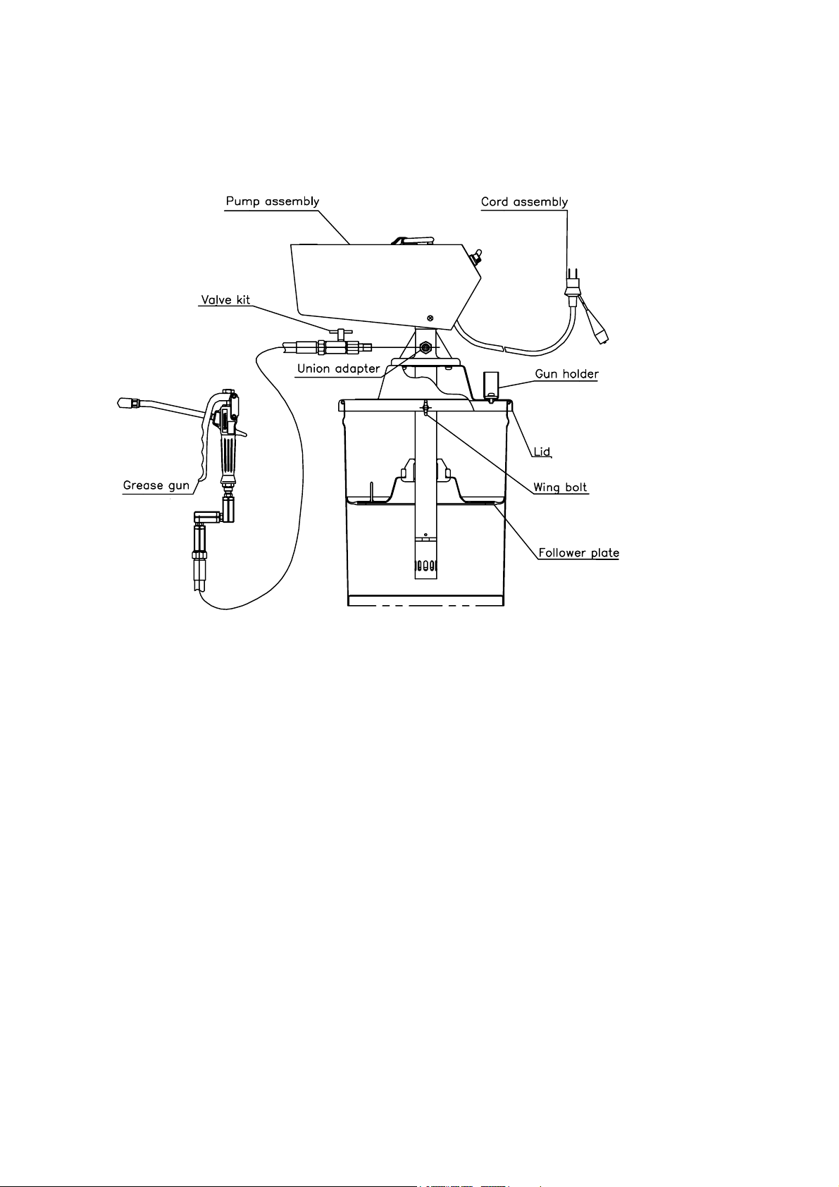
1. Names and Materials of Parts
1.1 Names and Materials of Parts
1.2 Contents of Package
This machine is packaged in a corrugated fiberboard case. Open the top lid of the corrugated fiberboard case and
check the machine for damage.
1
Page 6

2. Preparations before Operation
[Assembling the unit] (Fig. 1)
1) Insert the pump assembly in the center hole from the front side
of the lid.
2) Fix the pump assembly and the lid with 3 pan-head screws from
the rear side of the lid.
3) Connect the high-pressure hose for grease (separately
available) to the valve kit at the pump discharge port and
connect a high-pressure grease gun to the other end of the
hose.
[Setting the pump] (Fig. 1)
4) Remove the lid of a new grease can and set the attached follower plate.
Place the follower plate on the grease horizontally and push it down by
rubbing it to left and right with a hand until the grease comes out from
the packing in the middle of the plate.
<Note>
When using the follower plate for the first time after purchasing the
product, pack grease beforehand in the rear-side concave portion of
the plate. This facilitates the work. (Fig. 2)
5) Insert the pump in the packing in the middle of the follower plate and set
the lid on the pail can. Fix it securely by screwing 3 wing bolts equally.
<Note>
Take extreme care not to allow sand and dust to adhere on the suction tube and follower plate of the pump
assembly. Do not blemish the packing of the follower plate by the end of the lower pump.
[Connecting to power supply]
6) Place the unit on flat and stable place.
7) Connect the attached cord assembly (5 m) to the power supply.
Fig. 1
Fig. 2
CAUTION
- The applicable power source is AC-100V only.
[Bleeding air for grease] (Fig. 3)
8) The pump starts running by turning the switch ON. The first applied
grease includes the internal air of the pump. This is not a good
condition. Obtain a perfect condition by the next operation.
First open the valve kit and operate the pump until grease is discharged from a small hole under the check valve.
After grease is discharged in a perfect condition, close the valve kit. At this time, spread paper so that grease
may not come into touch with the hand, and dispose of the discharged grease.
<Note>
The grease in which air is mixed is cloudy in white.
9) Discharge the air-mixed grease completely from the high-pressure grease gun and the hose by pulling the gun
lever.
2
Fig. 3
Page 7

3. How to Operate the Machine
CAUTION
- Do not operate the gun lever with the discharge port facing to another person during machine
operation. A direct hit against the human body may result in an accident such as skin damage.
- Regarding a secondary accident such as hose damage that may be caused without shutting off of the
air supplied to the hose or installation contamination due to a leak from the valve or gun after
completion of the work or at night, the responsibility rests with the user side.
- When the pump causes a malfunction or operation stop, do not disassemble the pump thoughtlessly
and disassemble only necessary portions referring to the item pertaining to <Troubleshooting and
Corrective Measures> on page 4 and judging the situation properly.
<Note>
The electric grease pump runs continuously even if the grease gun closed. When internal pressure goes up to
28 MPa, the grease is relieved by relief valve automatically. Thus this unit is overload free. The grease returns
to pail through the outer tube.
1) Wipe the grease nipple to be used for greasing completely. After that,
push the hydro chuck of the high-pressure grease gun against the nipple
to perform chucking as vertically as possible. (Fig. 4)
2) Pull the lever of the high-pressure grease gun to supply grease. The
pump is automatically operated to supply grease. When grease is
normally injected, old grease will be squeezed out from the groove or
clearance bear the nipple.
3) After completion of grease supply, release the gun lever. The grease
supply will be stopped and the pump will also be stopped automatically.
4) Remove the hydro chuck of the grease gun. Since pressure is applied to
the hydro chuck, the head of the nipple may be broken if it is suddenly
pulled. Incline the hydro chuck to bleed the internal pressure and loosen
the claw bite, and the chuck can be easily removed. (Fig. 5)
5) After completion of greasing work or when the pump is not used for a long
time, be sure to shut off the supply air and bleed the internal air of the
pump, grease gun, and hose by operating the gun lever.
6) If the pump is suddenly started, it may be due to non-existence of grease
in the grease can or a cavity produced. Stop the greasing work and make
a check. If the grease is used up, replace the grease can.
[Replacing the grease can]
Fig. 4
Fig. 5
CAUTION
- When replacing the grease can, be sure to shut off the supply air for safety and pull the gun lever to
bleed the internal pressure of the pump and hose beforehand.
7) Unscrew the 3 wing bolts of the lid, and remove the pump unit from used the grease can and take out the follower
plate.
8) Remove the lid of a new grease can and place the follower plate on the grease horizontally and push the follower
plate by rubbing it until grease comes out from the central hole.
9) Insert the pump in the packing in the middle of the follower plate and set the lid on the pail can. Screw the 3 wing
bolts equally so fix the lid securely.
3
Page 8

4. Maintenance and Inspection
4.1 Troubleshooting and Corrective Measures
Symptom Contents of inspection Corrective measure
♦ The pump fails to start. - Check if the power cable is cut.
- Check if the fuse is blown.
- Uninstall the lower pump and operate
only by the motor.
↓
(Separate the lower pump and operate
the pump with only the motor.)
→ If the pump is operated, the lower
pump is defective.
→ If the pump is not operated, the
motor is defective.
♦ The pump is operated
but does not feed the
material by pressure.
♦ The pump is operated
but the pressure and
flow rate are insufficient.
♦ Grease leaks from the
motor.
- Check if the delivery hose and grease
gun is clogged up.
- Check if the grease is ran out.
- Check if the grease does not touch to
the pump suction because of cavity or
diagonal installation of the follower
plate.
- Uninstall the lower pump and operate
only by the motor.
- Check if leakage is found on the
connection of valve kit, hose and gun.
- Check if the relief valve is loosens.
- Check if the valve seat at lower pump
is worn out.
- Check if the seal packing between
motor and material pump is worn out.
♦ The pump makes noise. - Check if foot valve is stuck by foreign
substance.
4.2 Maintenance and Inspection
- Change to the new cable.
- Change to new fuse (7A).
- Repair service for the lower pump.
- Repair service.
- Remove the cause of clogging.
- Replace to the new pail.
- Install the follower plate horizontally
and push down till the grease comes
out from the packing. Then operate
the pump again.
- Check the lower pump.
- Tighten the connections
- Adjust the relief valve at proper
position.
- Change to new valve seat.
- Change to new seal packing.
- Remove the foreign substance.
The hose is a consumable part. Check it periodically. If any blemish or leakage is found, replace the hose little
earlier. The packing and slide portion parts of the pump are worn away. Check and replace them once a year.
4
Page 9

5. Disassembly and Assembly
CAUTION
- Gasoline is a high volatile fuel. Do not use it to clean the pump in any case, otherwise ignition or
explosion may be caused.
- When washing parts, do not use such a liquid as corrodes aluminum, copper alloy, iron, etc.
- Before disassembling and inspecting the machine, be sure to shut off the power supply and open the
outlet valve to release the internal pressure of the pump.
[Disassembling the lower pump]
When the trouble such as unstable operation or pump stop, do not
disassemble the pump immediately. First refer <Troubleshooting
and Corrective Measures> on page 4 and confirm the situation of
the pump unit. Do not disassemble the part that is not concerned
with the trouble.
1) Shut off the power supply. Bleed the internal pressure of the
pump and hose and remove the air chuck and high-pressure
hose form the pump.
2) Unscrew 3 wing bolts that fix the lid and the pail, and dismount
the unit from pail.
3) Unscrew 3 pan-head screws that fix the pump and the lid, and
disassemble the lid from the pump.
4) Fix the pump assembly on vise. (Fig.6)
5) Set a spanner on the valve adapter and unscrew it. The out
tube can be pulled out from the pump. Then continue to pull
out it until touching to the plate, the union that connects to the
motor. Pull out the pin and unscrew the union, and the lower
pump can be separated from the motor. (Fig. 6)
6) Pull out the out tube. If only the valve adapter pulled out,
unscrew the nut and remove the plate. Then pull out the out
tube and screw the suction tube with pipe wrench (set on
notched part of the suction tube). Pull out the pin and unscrew
the union, and the lower pump can be separated from the motor.
(Fig. 6, 7)
7) Fix the cylinder part of the lower pump on vise. Set a spanner
on the valve adapter and unscrew it. The valve seat, the foot
valve and the valve ring can be removed. (Fig. 8)
8) Set a pipe wrench on notched part of the suction tube and
unscrew it. The piston valve assembly can be removed.
(Fig. 9)
9) Flatten the bending part of the washer that fixes the union and
the piston. Separate the union and the piston with a spanner,
and then remove the ball and the spring. (Fig. 9)
10) Wash each part and if damage and wear found, change to the
new parts. Especially if the metal seal parts are damaged or
wear out, grease will leak and discharge pressure cannot be
increased, and consequently discharge volume will be
decreased. In this case the piston and the cylinder must be
changed to the new parts simultaneously. (Fig.10)
Fig.6
Fig.7
Fig. 9
Fig. 8
Fig.10
5
Page 10

[Assembling the lower pump]
- Assembling the intake valve
11) Insert the ball into the piston. Insert the spring into the union.
Put the washer between the piston and the union, and then
connect each other. This time keep the both edge of the
washer right-angled position against the side of the hexagon
part of the union. Then screw the union with a spanner and fix
to the piston firmly. Bend the both edge of the washer to the
direction to the union. This plays a role of stopper. (Fig.11)
- Assembling the foot valve
12) Insert the intake valve assembly to the suction tube.
(Fig.12)
13) Insert the valve ring, the foot valve and the valve seat in
order of it. Be sure the direction of each part is correct.
(Fig.12)
14) Screw the valve adapter and the tube.
Install the plate with the nut. (Fig.12)
15) Insert the suction tube from opposite side of valve adapter.
Pull out the union from the suction tube and screw it to the
connecting rod of the motor side. Adjust the position of
pin-hole of both the suction and the union, and insert the pin.
(Fig. 6)
16) Screw the suction tube into the crankcase of the upper motor
with hands. Then fix it firmly by a spanner.
[Disassembling the upper motor] (Fig.13)
17) Remove the packing retainer with tweezers.
18) Remove the packing and the back up ring with tweezers.
19) When replace these to new parts, put little grease on the
packing and install with correct direction.
[Adjusting the relief valve] (Fig.14)
The relief valve is adjusted its pressure to 28 MPa and fixed in
assembling at factory. Basically adjusting is not necessity.
If the relief valve is loosened by some reason, adjust with the
procedure shown below.
Fig.11
Fig.12
Fig.13
Fig.14
CAUTION
If the following points are not defended, the accident resulting
In injury or death and damage might be caused.
1. Remove the delivery hose and the valve kit, and then install
high-pressure ball vale with pressure gauge (Max. 50 MPa)
instead of the hose and the valve kit.
2. Operate the pump. After checking grease discharge, shut
off the high-pressure ball valve. Adjust the relief valve to
make the pressure gauge points 28 MPa. Tighten the nut
and fix the relief valve firmly.
3. [Adjusting method without pressure gauge]
One revolution from the position where the bolt touched the
guide increases relief pressure approx 26 MPa. Screw the
bolt 30 degree more, then tighten the nut and fix the bolt.
(Fig.15)
6
Fig.15
Page 11

y
r
r
r
r
r
y
6. Parts Disassembly Drawing and Parts List
6.1 880899 EPL-100
REF.No.
6.2 851985 Grease gun
REF.No.
REF No.3,8,9 and No.10 are undissolution.
Parts No.
1 851985 Grease gun assembly 1
2 680080 Union adapter 1
3 803903 Valve kit 1
4 710915 Lid 1
7 683347 Screw with washe
8 803662 Cover assembly 1
9 852902 Grease pump assembly 1
10 602296 Pan-head screw 3
11 631418 Spring lock washe
12 610623 Wing bolt 3
13 803085 Follower plate assembly 1
14 707937 Gun holde
15 602298 Pan-head screw 1
16 707880 Plain washe
18 683860 Screw with washe
19 695034 Hose 1
Parts No.
1 627641 Nut 1
2 711750 Bolt 1
3 711354 Lever 1
4 711444 Retaining nut 1
5 772160 Packing 2
6 713638 Washer 1
7 711357 Rod 1
8 711352 Body 1
9 711351 Link 1
10 683201 Rivet 2
11 800531 Nozzle assembly 1
12 685728 Cap 1
13 630314 Ball 1
14 711445 Spring retainer 1
15 711446 Spring 1
16 640011 O ring 1
17 710971 Union 1
18 802910 Swivel joint assembly 1
Description Q't
Description Q't
2
4
1
1
2
7
Page 12

y
r
6.3 852902 Pump assembly
REF.No.
10 713240 Rink 1 42 630313 Ball 1
11 682995 Needle bearing 1 43 801051 Cylinder assembly 1
12 684347 Ball bearing 2 44 632754 Spring pin 1
13 832192 Connecting rod 1 45 709642 Suction tube 1
14 640009 O ring 1 46 702977 Washer 2
15 640014 O ring 1 47 706399 Plunger rod 1
16 710813 Bush 1 48 706072 Foot tube 1
Parts No.
Description Q'tyREF.No.
1 682262 Bolt 4 36 702971 Pin 3
2 713239 Washe
5 832933 Cover assembly 1 38 709643 Rod 1
6 713231 Cam 1 39 702975 Union 1
7 713230 Stopper 2 40 702974 Washer 1
9 716029 Key 1 41 702976 Spring 1
17 771405 Back up ring 1 49 710815 Out tube 1
18 771418 U-Packing 1 50 702980 Valve ring 1
19 715988 Crank case 1 51 771404 Foot valve 1
20 640037 O ring 1 52 702982 Valve seat 1
22 710896 Packing retainer 1 53 830407 Valve adapter 1
23 710808 Pin 1 54 712043 Tube 1
24 630779 Stop ring 2 55 702984 Plate 1
25 682994 Inner case 1 56 627010 Nut 1
26 684336 Motor 1 57 632019 Split pin 1
27 802587 Relief valve assembly 1
Parts No.
Description Q't
237706091Union 1
8
Page 13

7. Specification
7.1 Specification
Type EPL-100
Model No. 880899
Rating Continuous rating
Discharge volume 2~3.17g/sec
Discharge pressure 0~28MPa
Max discharge pressure 28MPa (30 minute rating)
Rotational speed 90 ~ 145 RPM
Power supply AC-100 V ( 50/60 Hz )
Vibration resistance 3.5 G
Applicable grease NLGI No.0 ~ 2
Applicable temperature -10 °C ~ 40 °C
Weight 13 kg
Equipped accessories 851985 Grease gun
803085 Follower plate
802493 Cord assembly (5 m, with connector)
710915 Lid
695034 High-pressure delivery hose ( G1/4x2.5M )
803903 Valve kit
Option 851245 Hose reel ( SHR-3C15 )
851243 Hose reel ( SHR-3C10 )
851003 Carry ( S-20 )
683239 Dustproof cover
7.2 Dimensions
9
Page 14

8. Limited Warranty
● This product is shipped to customers only after meeting strict inspection standards. If an abnormality occurs
during normal operation in accordance with the operating instructions and other operating cautions within the
warranty period (12 months after date of purchase) that can be attributed to a manufacturing defect, the defective
parts of this product will be serviced or the product will be replaced free of charge. However, this warranty will not
cover compensation for incidental damage or any malfunction listed below.
1. Warranty period
This warranty will be valid for a period of 12 months after the date of purchase.
2. Warranty
If, during the warranty period, any of the material of the genuine parts of this product or the workmanship of this
product is found defective, and is so verified by our company, the servicing cost will be fully born by our company.
3. Exclusion
Even during the warranty period, this warranty does not cover the following:
1) Malfunction arising from use of parts other than manufacturer-specified genuine parts
2) Malfunction arising from misuse or operating errors, or lack of storage or maintenance care
3) Malfunction arising from use with a fluid that may cause corrosion, inflation or dissolution of the component
parts of the product
4) Irregularity arising from repair made by other than by our firm, our regional office, dealer or authorized service
personnel
5) Malfunction arising from modification of the product by other than authorized service personnel
6) Wear and tear of parts that must be regularly replaced in the course of normal operation, such as packings,
O-rings, balls, and valve seats
7) Malfunction and/or damage due to transportation, moving or droppage of the product after purchase
8) Malfunction and/or damage due to fire, earthquake, flood or other force majeure
9) Malfunction arising from use of compressed air that contains impurities or excessive moisture, or use of
gases or fluids other than the specified compressed air
10) Malfunction arising from use with a fluid that causes excessive abrasion or use of lubricating oil other than
that specified for this product
Furthermore, this warranty does not cover the rubber parts, or other parts that are subject to wear in normal
operation, used in this product and its accessories.
4. Parts
Parts for this product will be kept available for 5 years after discontinuation of production. Once 5 years have
elapsed after close of production, availability of parts for this product cannot be guaranteed.
10
Page 15

Manufactured by
YAMADA
CORPORATION
INTERNATIONAL DEPARTMENT
No.1-3, 1-Chome, Minami-Magome, Ohta-ku, Tokyo, 143-8504, Japan
PHONE : +81-(0)3-3777-0241
FAX : +81-(0)3-3777-0584
201005 OSA037U
 Loading...