

YAMADA DP-20F/P, DP-25F/C, DP-38F/C, DP-38F/P, DP-25F/P Maintenance Manual

MAINTENANCE MANUAL
YAMADA AIR-OPERATED DOUBLE DIAPHRAGM PUMP
DP-20F/P
DP-25F/P
DP-25F/C
DP-38F/P
DP-38F/C
Doc. No. NDP403M-05
WARNING
- For safety’s sake, be sure to read this maintenance manual thoroughly before starting
maintenance for this product. After reading the manual, keep it in an easy-to-access place so
that the user may refer to it whenever necessary.
This maintenance manual describes the items required for maintenance of the Yamada DP-F/P, DP-F/C
series Diaphragm Pumps.
This document is based on the products that are manufactured in March 2011. NOTE that its contents are
subject to change as a result of specification changes to be made in future.
- Warnings and Cautions
To use this product safely, be sure to observe the contents of the following description. In this manual,
warnings and cautions are indicated by using symbols. These symbols are intended to prevent death or
serious injury that may be caused to the operator or those who are around the product and damage that
may be caused to the articles that are around the product, as well as to use the product safely and correctly.
Each symbol is indicated and has a meaning as shown below. Read the description with a good
understanding of its contents.
WARNING :
This indicates the existence of potential hazard which, if not
avoided, will result in death or serious injury.
CAUTION :
This indicates the existence of potential hazard which, if not
avoided, may result in bodily injury or in physical damage.
To indicate the contents of danger and damage, the following symbols are used together with the above
indications.
This symbol indicates an act that is prohibited (prohibition). The concrete contents of
prohibition are indicated by the side of the indication.
This symbol indicates the contents that must be observed. The concrete contents of
observance are indicated by the side of the indication.
WARNING
- Before starting the maintenance work, shut off the supply air and clean the pump. If air
pressure or residual liquid remains in the pump, damage or explosion may be caused to the
product or serious injury or death may be caused if it sticks on the eyes or skin or inhaled or
swallowed. (For cleaning the pump, refer to Chapter 6 of the Operation Manual.)
- When replacing parts, be sure to use the genuine parts or equivalents. Using parts other than
these parts may result in a fault.
(Refer to Exploded View and Reminder to order correct item on the separate sheets.)
CAUTION
- When it is indicated that dedicated tools should be used, be sure to use these dedicated tools,
otherwise the pump may be damaged.
- Check the weight of the pump by referring to 10.1 Main Specifications in the operation manual
and take extreme care when lifting it.

Table of Contents
·Warnings and Cautions
·Table of Contents
1.Principles of operation--------------------------------------------------------------- 1
2.Tools, etc.
2.1 General tools ---------------------------------------------------------------------- 1
2.2 Special tools ----------------------------------------------------------------------- 1
2.3 Others ------------------------------------------------------------------------------- 1
3
.Balls, Flat valves and Valve seats
3.1 Removal ---------------------------------------------------------------------------- 2
3.2 Inspection
■Ball valve types ------------------------------------------------------------------ 3
■Flat valve types------------------------------------------------------------------ 3
3.3 Installation ------------------------------------------------------------------------ 3
4.Diaphragm and Center rod
4.1 Removal ············································································ 4
4.2 Inspection -------------------------------------------------------------------------- 5
4.3 Installation ------------------------------------------------------------------------ 5
5.Pilot valve Assembly, Valve Seats
5.1 Removal ············································································ 6
5.2 Inspection --------------------------------------------------------------------------6
5.3 Installation ------------------------------------------------------------------------7
6.C Spool valve Assembly and Sleeve Assembly
6.1 Removal ············································································ 7
6.2 Inspection --------------------------------------------------------------------------9
6.3 Installation -----------------------------------------------------------------------10
7.Retightening of Tie rods --------------------------------------------------------10
8
.Instructions for applying lubrication······································ 11
8.1 Applying Lubricant to the Packing ········································ 11
8.2 Applying Lubricant to the Center Rod ----------------------------------11
8.3 Assembly --------------------------------------------------------------------------11
1
Fig.2.1 Fig.2.2
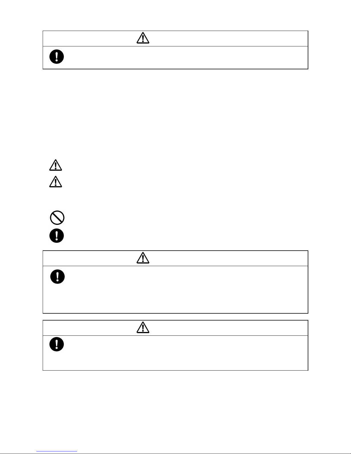
1. Principles of operation
There are two diaphragms fixed to the center rod, one at each end. When compressed air is supplied to air
chamber b (right side, see Fig.1.1), the center rod moves to the right, the material in material chamber B is
pushed out, and at the same time material is sucked into material chamber A.
When the center rod is moved full-stroke to the right, the air switch valve is switched, compressed air is sent to
air chamber a (left side, see Fig.1.2), and the center rod moves to the left. The material in material chamber A is
pushed out, and at the same time material is sucked into material chamber B.
Through repetition of this operation, material is repeatedly taken in and discharged out.
2. Tools, etc.
2.1 General tools
・Socket wrenches 10 mm, 13 mm, 17 mm
・Open-end wrenches 13 mm, 17 mm
・Hexagonal wrench
・Snap ring pliers
・Flat head screwdriver
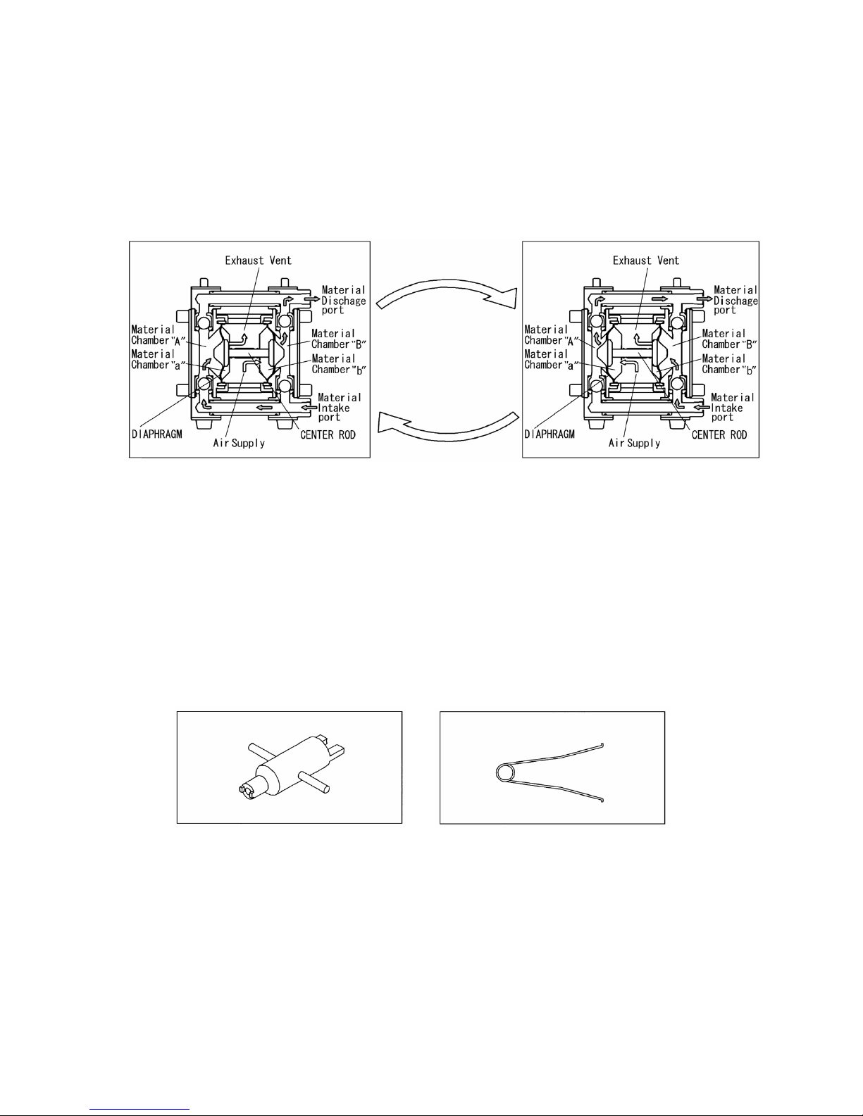
2.2 Special tools (sold separately)
・Pilot valve remover ・Sleeve remover
For pilot valve, cap and valve seat For sleeve
Part No. 712606 Part No. 713148
2.3 Others
・Assembly lubricant (oil) Fomblin® Y25 or equivalent
・Assembly lubricant (grease) Fomblin® GR AR555 or equivalent
2
Fig.3.1
Fig.3.2
Fig.3.3
Fig.3.4
Fig.3.5
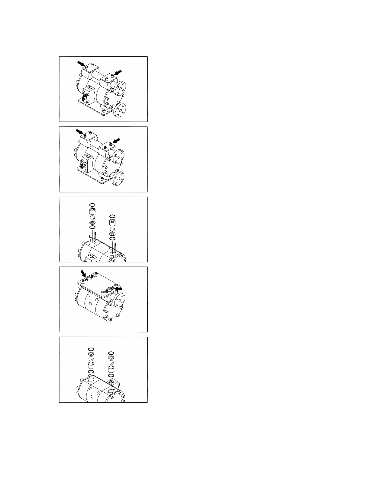
3. Balls, Flat valves and Valve seats
3.1 Removal
▪ Remove the 8 caps (4 on the top and 4 on the bottom) from
both sides of the vertical tie rods. [Fig.3.1]
▪
Unscrew the 4 retainer nuts from the upper side of the
vertical tie rods. Then, remove the reinforcement plates,
O rings, and out manifolds. [Fig.3.2]
▪ Remove the O rings, valve stoppers, valve guides, balls or
flat valves, and valve seats. [Fig.3.3]
▪ Turn over the body assembly. [Fig.3.4]
▪ Pull out the four vertical tie rods and remove the base and
in-manifold. [Fig.3.4]
▪ Remove the O rings, valve seats, balls or flat valves, valve
guides and valve stoppers. [Fig.3.5]
 Loading...