

Page 1

MAINTENANCE MANUAL
YAMADA AIR-OPERATED DIAPHRAGM PUMPS
DP-10Fi
DP-20Fi
Doc. No. NDP 149M-06
Page 2
WARNING
- For safety’s sake, be sure to read this maintenance manual thoroughly before starting
maintenance for this product. After reading the manual, keep it in an easy-to-access place so
that the user may refer to it whenever necessary.
This maintenance manual describes the items required for maintenance of the Yamada DP-Fi series
Diaphragm Pumps.
This document is based on the products that are manufactured in March 2011. Note that its contents are
subject to change as a result of specification changes to be made in future.
- Warnings and Cautions
To use this product safely, be sure to observe the contents of the following description. In this manual,
warnings and cautions are indicated by using symbols. These symbols are intended to prevent death or
serious injury that may be caused to the operator or those who are around the product and damage that
may be caused to the articles that are around the product, as well as to use the product safely and correctly.
Each symbol is indicated and has a meaning as shown below. Read the description with a good
understanding of its contents.
WARNING :
This indicates the existence of potential hazard which, if not
avoided, will result in death or serious injury.
CAUTION :
This indicates the existence of potential hazard which, if not
avoided, may result in bodily injury or in physical damage.
To indicate the contents of danger and damage, the following symbols are used together with the above
indications.
This symbol indicates an act that is prohibited (prohibition). The concrete contents of
prohibition are indicated by the side of the indication.
This symbol indicates the contents that must be observed. The concrete contents of
observance are indicated by the side of the indication.
WARNING
- Before starting the maintenance work, shut off the supply air and clean the pump. If air
pressure or residual liquid remains in the pump, damage or explosion may be caused to the
product or serious injury or death may be caused if it sticks on the eyes or skin or inhaled or
swallowed. (For cleaning the pump, refer to Chapter 6 of the Operation Manual.)
- When replacing parts, be sure to use the genuine parts or equivalents. Using parts other than
these parts may result in a fault.
(Refer to Exploded View and Reminder to order correct item on the separate sheets.)
CAUTION
- When it is indicated that dedicated tools should be used, be sure to use these dedicated tools,
otherwise the pump may be damaged.
- Check the weight of the pump by referring to 10.1 Main Specifications in the operation manual
and take extreme care when lifting it.
Page 3

Table of Contents
· Warnings and Cautions
· Table of Contents
1. Principles of operation ·························································· 1
2. Tool and Others Required
2.1 General tools ······································································ 1
2.2 Dedicated tools ··································································· 1
2.3 Others.·············································································· 2
3. Ordering Replacement parts ················································· 2
4. Base
4.1 Removal ············································································ 3
4.2 Installation ········································································ 3
5. Valve Body and C Spool Valve Assembly
5.1 Removal ············································································ 4
■ Valve body assembly ·························································· 4
■ Disassembling of the C Spool Valve ······································ 6
5.2 Inspection ·········································································· 7
5.3 Installation ········································································ 8
6. Ball Valves and Valve Seats
6.1 Removal ············································································ 9
6.2 Inspection ·········································································10
6.3 Installation ·······································································10
7. Diaphragm and Center Rod
7.1 Removal ··········································································· 11
7.2 Inspection ·········································································13
7.3 Installation ·······································································13
8. Pilot Valve Assembly
8.1 Removal ···········································································15
8.2 Inspection ·········································································15
8.3 Installation ·······································································15
9. Retightening of Tie rods ·······················································16
Page 4
1
1. Principles of operation
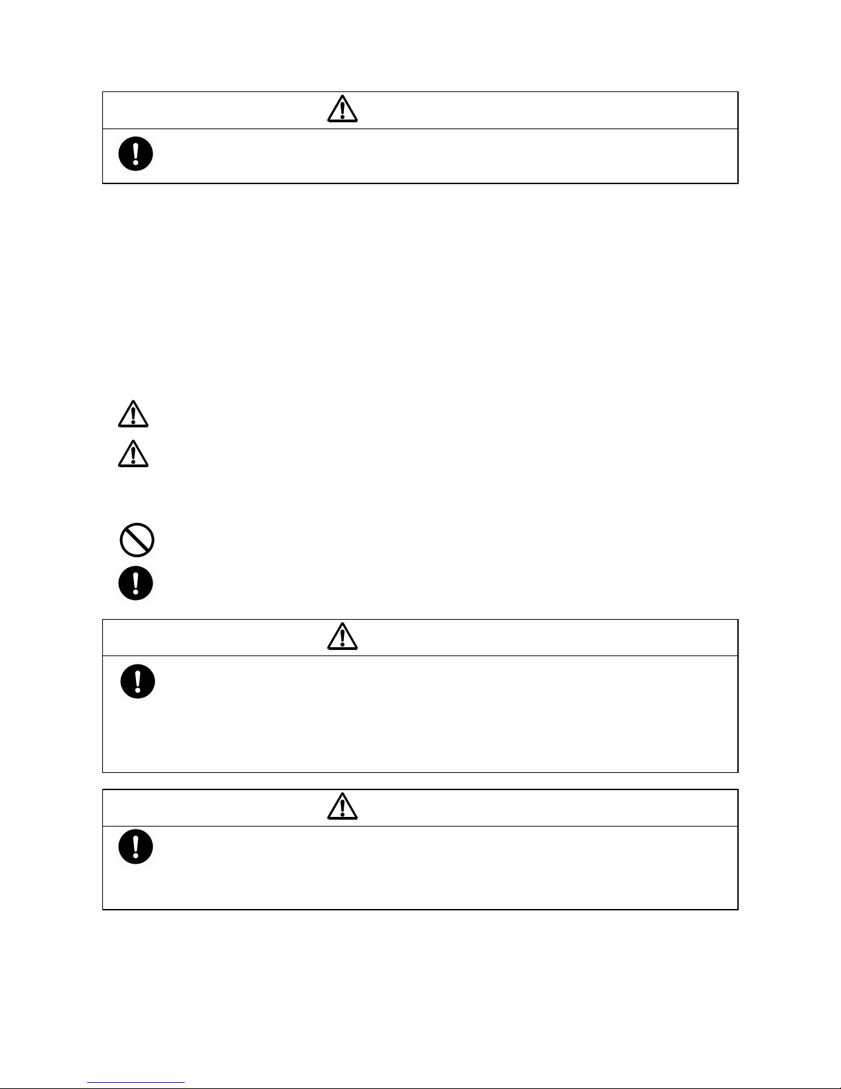
Liquid material chambers are located inside and air chambers are located outside of the DP-Fi
series pump.When compressed air is supplied to the air chamber “a” (see the left figure below) by the
switch valve of this pump, the center rod starts moving to the left to cause liquid in the liquid
material chamber “A” to be pushed out to the discharge port, and at the same time liquid is sucked
into the liquid material chamber “B”.
When the center rod moves full-stroke to the left, the switch valve is automatically switched,
compressed air is sent to the air chamber “b”, and the center rod moves to the right, that is, toward
the opposite direction (see the right figure).
As the result, liquid in the liquid material chamber “B” is pushed out to the discharge port, and at
the same time liquid is sucked into the liquid material chamber “A”.
Thorough repetition of this operation, liquid is repeatedly taken in and discharged out to construct
a diaphragm pump.
2. Tools and Others Required
2.1 General tools
・Socket wrenches 13 mm , 19 mm ・Flat head screw driver
・Open-end wrenches 13 mm , 19 mm ・Snap ring pliers
・Hexagonal wrench 6 mm
・ Plyer
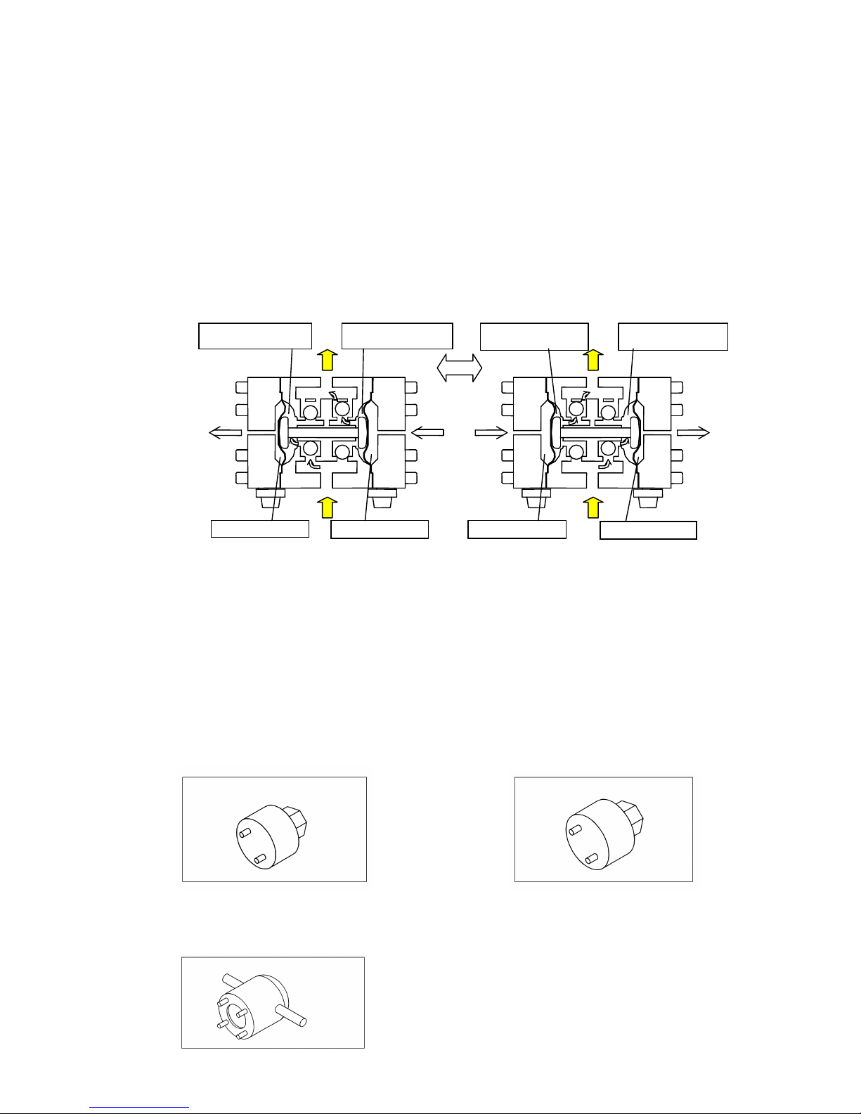
2.2 Dedicated tools
① Valve cap remover (supplied)
Purpose: Removing the valve cap and
valve stopper.
(Part No. for DP-10Fi: 832516)
② Valve cap remover (Fi/□/R only supplied)
Purpose:
DP-10Fi, DP-20Fi: Removing the valve cap
DP-20Fi: valve stopper.
(Part No. for DP-20Fi: 832517)
③ Guide holder remover (optional)
Purpose:
DP-10Fi, DP-20Fi: Removing the guide holder and spring seat.
(Part No. 832518)
Liquid material
chamber “B”
Air Chamber ”b”
Air Chamber “a”
Air Chamber “b”
Air Chamber “a”
Liquid material
chamber “A”
Liquid material
chamber “B”
Liquid material
chamber “A”
Page 5
2
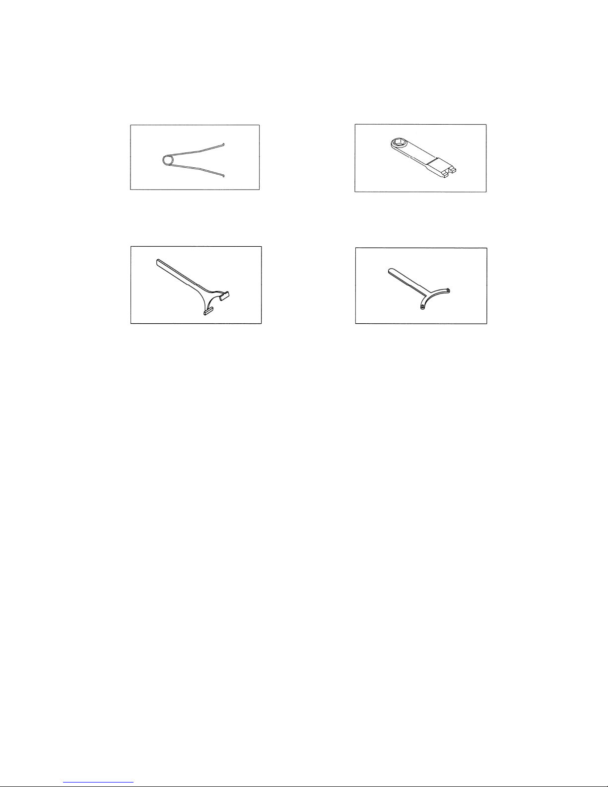
④ Sleeve remover (optional)
Purpose: Removing sleeves, valve seat and
funnel.
(Part No. 713148)
⑤ Cap remover (optional)
Purpose: Removing a cap.
(Part No. 771132)
⑥ Ring Wrench
DP-10Fi/
□/H (Part No. 832802)
DP-20Fi/
□/H (Part No. 832803)
⑦ Support Ring Wrench
DP-10Fi/
□/H (Part No. 832804)
DP-20Fi/
□/H (Part No. 832805)
2.3 Others.
・ Assembly lubricating oil Fomblin® GR AR555 or equivalent
・ Bolts M8 ×1.25×30 or larger
3. Ordering Replacement parts
For accurate and speedy shipment of parts, be sure to order the right parts for your model to
distributor.
Indicate the part numbers, descriptions, and quantities.
Page 6

3
4. Base
4.1 Removal(only Fi/□/R)
Follow the steps below to separate the pump main unit from the base.
・ Remove the fixing screw (one). [Fig.4-1]
・ Slide the pump main unit toward the fixing screw, then
raise and remove it from the base. [Fig.4-2]
4.2 Installation
For installation, see [Exploded View] on the separate sheet and install in the reverse order of
disassembly.
Page 7

4
5. Valve Body and C Spool Valve Assembly
5.1 Removal
■ Valve body assembly(Fi/□/R)
・ Remove the cap from each hexagon-headed bolt (part
“a”). [Fig.5-1]
・ Remove the hexagon-headed bolts (four).
・ Put the bolt (M8 × 1.25 × 30 or larger) on the tip of the
pin (part “b”), and screw it. Pull out the pin towards
the up direction to remove it.
<NOTE>
- To pull out a pin of the part “b”, use the hexagon-headed
bolt removed from the part “a”.
・ Remove the valve body assembly and the piping blocks
A and B from the pump. [Fig.5-2]
・ Remove the piping block assembly from the valve body
assembly.
・ Use the dedicated tool ⑤(cap remover) to remove the
cap from the valve body assembly. [Fig.5-3]
・ Use a plyer remove the C spool valve assembly.
[Fig.5-4]
・ Use the dedicated tool ④(sleeve remover) to remove a
sleeve. [Fig.5-5]
Page 8

5
■ Valve body assembly(Fi/□/H)
・Remove air tube from fitting.〔Fig.5-6〕
・
Screw in bolt (M8×1.25×30)and pull up pin then remove
pin.
・Remove valve body from pump body.
・Remove air tube from fitting〔Fig.5-7〕
・Use the dedicated tool ⑤ (Cap remover) to remove cap
from valve body assembly.〔 Fig.5-8〕
・Use a plyer remove C Spool assembly. 〔 Fig.5-9〕
・ Use the dedicated tool ④ (Sleeve remover) to remove
sleeve.
〔Fig.5-10〕
Fig.5-6
Fig.5-7
Fig.5-8
Fig.5-9
Fig.5-10
Page 9

6
■ Disassembling of the C Spool Valve
・ Use a flat-blade screwdriver to raise the outside of the
C spring so that the outside can be opened, and remove
the C spring. [Fig.5-11 and 5-12]
<NOTE>
- When you remove the C spring, the arm is removed
also.
・ Use the snap ring plyer to remove the interlocking
bush from the spool while opening and pushing the
groove of the interlocking bush. [Fig.5-13 and 5-14]
<NOTE>
- Do not exert any excessive force to the spool.
- Do not open the groove of the interlocking bush
more widely than it has to.
- When you remove the interlocking bush, the spring
retaining cushion is removed also.
Fig.5-11
Fig.5-12
Fig.5-13
Fig.5-14
Page 10

7
5.2 Inspection
・ Spool
Measure the outside diameter, and if it is out of the
allowable range, replace the spool with a new one.
[Fig.5-15]
Allowable range of the spool
DP-10Fi/P/
□
DP-20Fi/P/□
φ15.73 ~ φ 15.80 mm
DP-10Fi/C/□
DP-20Fi/C/□
φ15.77 ~ φ 15.80 mm
・ Sleeve
Measure the inside diameter, and if it is out of the
allowable range, replace the sleeve with a new one. If
the sleeve is cracked or damaged, replace it. [Fig.5-16]
Allowable range of the Sleeve
DP-10Fi/P/
□
DP-20Fi/P/□
φ15.80 ~ φ 15.86 mm
DP-10Fi/C/□
DP-20Fi/C/□
φ15.80 ~ φ 15.82 mm
・ O rings
If the O ring is worn out or cracked, replace it with a
new one. [Fig.5-11]
<NOTE>
- Be sure to replace the spool and sleeve together as a
complete set.
・ C spring
Measure the dimension shown on the left figure, and if
it is out of the allowable range, replace the C spring.
[Fig.5-17]
Allowable range of the C spring
25.9 ~ 26.5 mm
・ Interlocking bush
Measure the dimension shown on the left figure, and if
it is out of the allowable range, replace the interlocking
bush with a new one. [Fig.5-18]
Usable range of Interlocking bush
Part to measure “a”
4.8 ~ 5.0 mm
Part to measure “b”
6.8 ~ 7.1 mm
・ Arm
Measure the dimension shown on the left figure, and if
it is out of the allowable range, replace the arm with a
new one. [Fig.5-19]
Usable range of Arm
10.5 ~ 10.9 mm
・ Spring bearing
If the spring bearing is worn out or cracked,
replace it with a new one. [Fig.5-20]
・ Cushion
If the cushion is worn out or cracked, replace
it with a new one. [Fig.5-20]
Fig.5-15
Fig.5-16
Fig.5-17
Fig.5-18
Fig.5-19
Fig.5-20
Page 11

8
5.3 Installation
For installation, see [Exploded View] on the separate sheet and install in the reverse order of
disassembly.
Tightening torque of the hexagon-headed bolt of the piping block
DP-10Fi/□/R
DP-20Fi/
□/R
4 N・m
<NOTE>
- Make sure there is no dust on the seal surface and the
seal is not damaged.
- Be sure to fix the caps on both edges of the valve body
until they reach the end face of the valve body.
Page 12

9
6. Ball Valves and Valve Seats
6.1 Removal(Figure displays Fi/□/R)
・ Use the dedicated tool (valve cap remover) to remove
the valve cap and valve stopper. [Fig.6-1 and 6-2]
(Dedicated tool ① for DP-10Fi or dedicated tool②for
DP-20Fi)
・ Remove the O ring.
・ Remove the balls, valve seats, O rings and funnel.
Be sure to use the dedicated tool ④(sleeve remover) to
remove the funnel and valve seat. [Fig.6-3]
(Fi/□/R) (Fi/□/H)
Dedicated tool
Valve c ap
Valve stopper
O ring
O ring
O ring
Valve s e at
Valve s e at
Funnel
Dedicated tool
Valve c ap
Valve stopper
Valve s e at
O ring
Funnel
Valve s e at
O ring
Fig.6-4
O ring
Page 13

10
6.2 Inspection
■Ball valve
・ Ball [Fig.6-5]
Measure the outside diameter, and if it is out of the
allowable range, replace the ball with a new one.
Allowable range of the ball
DP-10Fi Sφ 14.3 ~ Sφ16.3 mm
DP-20Fi Sφ 24.3 ~ Sφ27.8 mm
・ Valve seat [Fig.6-6]
Measures the dimension shown on the left figure, and if
it is out of the allowable range, replace the valve seat
with a new one.
Allowable range of the valve seat
DP-10Fi 2.4 ~ 5.9 mm
DP-20Fi 2.8 ~ 7.0 mm
6.3 Installation
For installation, see [Exploded View] on the separate sheet and install in the reverse order of
disassembly.
Tightening torque for the valve stopper and valve cap
DP-10Fi, DP- 20Fi 20 N・m
<NOTE>
Make sure there is no dust on the seal surface and
the seal is not damaged.
Be sure to replace the PTFE O ring with a new one.
Page 14

11
7. Diaphragm and Center Rod
7.1 Removal Fi/□/R
・ Remove the base,valve body assembly and piping block
in the way instructed in Section “4.1 Removal” of “4.
Base” and “valve body assembly” of “5.1 Removal.”
[Fig.7-1]
・ Remove the 12 caps from the both sides of horizontal
tie rods.
・ Remove the six retainer nuts from one side of the
horizontal tie rods, then remove the reinforcement
plate, air chamber and diaphragm.
・ White removing the O rings, remove the rod.[Fig.7-3]
・ Turn the center disks on the side of the horizontal
center rod with your hands to remove them. [Fig.7-4]
・ Use the dedicated tool ③ (guide folder remover) to
remove the guide folder.[ Fig.7-5]
・ Remove the guide, center rod and sleeve. [Fig.7-6]
Dedicated tool
Cente
r
Sleeve
Center disk
Page 15

12
Disassemble Fi /□/ H
・ Refer to instructions for disassembling of the valve
body assembly. 〔 Fig.7-7〕
・ Use the dedicated tool ⑦ (Support Ring Wrench)
to loosen support ring.( turn180 degree Approx)
〔Fig.7-8〕
・ Use the dedicated tool ⑥ (Retaining Ring Wrench) to
remove retaining ring. 〔Fig.7-8〕
・ Insert Flat head screw driver into the groove to remove
diaphragm. 〔Fig.7-9,7-10〕
・Use the dedicated tool ③ (guide holder remover)
to remove the guide retainer. 〔Fig.7-11〕
・ Remove the guide, center Rod and sleeve.〔Fig.7-12〕
Fig.7-7
Fig.7-8
Fig.7-9
Fig.7-10
Fig.7-11
Fig.7-12
Page 16

13
O ring
Diaphragm
Center disk
Air chamber
Tie rod
Fig.7-16
7.2 Inspection
・ Diaphragm
If the diaphragm is worn out or damaged, replace it
with a new one.
Guideline of diaphragm life
(when used with clean water at room temperature)
DP-10Fi
12,000,000 cycle
DP-20Fi
6,000,000 cycle
・ Center rod [Fig.7-13]
Measure the diameter, and if it is out of the allowable
range, replace the center rod with a new one.
Allowable range
DP-10Fi, DP- 20Fi φ17.95 ~ φ 18.05 mm
・ Sleeve [Fig.7-14]
Measure the inside diameter, and if it is out of the
allowable range, replace the sleeve with a new one.
Allowable range
DP-10Fi, DP- 20Fi φ18.02 ~ φ 18.10 mm
・ Guide [Fig.7-15]
Measure the inside diameter, and if it is out of the
Allowable range, replace the guide with a new one.
Allowable range
DP-10Fi, DP- 20Fi φ18.02 ~ φ 18.10 mm
7.3 Installation
For installation, see [Exploded View] on the separate sheet and install in the reverse order of
disassembly.
・ Install the diaphragm so that its protruded
part can face the inside. [Fig.7-16]
・ An auxiliary board attaches a thick board side
outside.
Tightening torque for the tie rod
DP-10Fi/□ /R
DP-20Fi/
□/R
5 N・m
<NOTE>
- Make sure that there is not any dust on the
seal surface and that any sealed part cannot
be damaged.
- Manually tighten the center disk until it
stops.
- Tighten the tie rod with uniform force.
- Retighten the tie rods immediately before
starting the pump.
Sleeve
Guide
Guide holder
Center rod
Reinforcement plate
Part to measure
Fig.7-13
Fig.7-14
Fig.7-15
Page 17

14
For installation, see [Exploded View] on the separate sheet and install in the reverse order of
disassembly.
Tightening Torque values
DP-10 Fi/□/H 40 N・m
DP-20 Fi/□/H 60 N・m
<NOTE>
After fitting the retaining ring, point (A) must be in the
down position. Then tighten the inside support ring.
〔Fig.7-18〕
Fig.7-17
Fig.7-18
Page 18

15
8. Pilot Valve Assembly
8.1 Removal(Figure displays Fi/□/R)
・ Use the dedicated tool ③(guide holder remover) to
remove the spring seat. [Fig.8-1]
・ Remove the spring and the pilot valve assembly.
[Fig.8-2]
・Remove the valve sheet by using dedicated tool ⑤(cap
remover) [Fig.8-3]
8.2 Inspection
・ Spring [Fig.8-4]
Be sure to replace the spring with a new one when
Disassembling the pilot valve assembly.
・ O ring
If the O ring is worn out or damaged, replace it with a
new one.
・ Pilot valve
If the pilot valve is worn out or damaged, replace it
・ Valve sheet [Fig.8-4]
If the seat side of the pilot valve is worn out or damaged,
replace the pilot valve with a new one.
8.3 Installation
For installation, see [Exploded View] on the separate sheet and install in the reverse order of
disassembly.
Page 19

16
9. Retightening of Tie rods(only Fi/□/R)
・ Since the dimensions of this pump may vary according
to the temperature or with the passage of time due to
the characteristics of its material: resin. Therefore,
check to see if any liquid material leaks at each sealed
portion periodically, and retighten the parts indicated
with arrow marks. [Fig.9-1]
・ The torque should be applied:
① immediately before you use the pump,
② during inspection to be performed every six months.
③ during inspection to be performed every year if you
use the pump in the clean room, that is, if the pump
is used within ± 5ºC of the temperature variation.
④ if the pump starts when the temperature of liquid
material is low: the temperature of this material
becomes high when the pump operates, and becomes
low when the pump stops.
⑤ if any leak of liquid or material is detected with the
daily inspection.
Retightening torque of the tie rods
DP-10Fi, DP- 20Fi 5 N・m
Retightening torque of the valve cap
DP-10Fi, DP- 20Fi 20 N・m
<NOTE>
- Retighten the tie rod nut retainers on a diagonal
line with even force.
- Be sure to retighten the valve cap with the
dedicated tool (see P.4).
Page 20

Manufactured by
YAMADA
CORPORATION
INTERNATIONAL DEPARTMENT
No.1-3, 1-Chome, Minami- Magome, Ohta-Ku, Tokyo, 143-8504, Japan
PHONE : +81-(0)3-3777-0241
FAX : +81-(0)3-3777-0584
201612 NDP149M
 Loading...