

YAMADA DP-10/12 series, NDP-50 series, NDP-25 series, NDP-40 series, NDP-10/12 series Operation Manual
...Page 1

Doc. No. NDP002U-18
Issue 1998-6
Revised 2008-12
OPERATION MANUAL
OPERATION MANUAL
OPERATION MANUALOPERATION MANUAL
YAMADA AIR
YAMADA AIR----OPERATED DIAPHRAGM PUMPS
YAMADA AIRYAMADA AIR
OPERATED DIAPHRAGM PUMPS
OPERATED DIAPHRAGM PUMPSOPERATED DIAPHRAGM PUMPS
NDP-5 series
DP-10/12 series
NDP-10/12 series
NDP-15 series
NDP-20 series
NDP-25 series
NDP-40 series
NDP-50 series
NDP-80 series
DP-F series
Page 2

Name of company : YAMADA CORPORATION
Address : No,1-3,1-Chome,Minami-Magome,ohta-ku,Tokyo,143-8504 Japan
Declares, in sole responsibility, that the following product
Equipment : Diaphragm Pumps
Type : NDP- and DP- series
Referred to in this declaration conforms with the following standard(s) or directive(s)
YAMADA CORPORATION will keep on file for review for following
Technical documentation
Importer / Distributor in EU
Name of company : YAMADA EUROPE B.V.
Address : Aquamarijnstraat 50, 7554 NS Hengelo (O), The Netherlands
This product is certificated in TUV Rheinland about safety.
Certificate Number is R9850515
Place and date issued : Sagamihara Factory / May 16 2001
Name and signature as well as position of undersigned :
DECLARATION OF CONFORMITY
: - European Standard EN 809 / October 1998
: - Directive 98/37/EC
• operating instructions as required
• plans
• description of measures designed to ensure conformity
• other technical documentation
Hiromasa Kumagai (Quality assurance Dept. Director)
2
Page 3

····Introduction
Introduction
IntroductionIntroduction
Thank you for purchasing a Yamada Diaphragm Pump. This product is a positive-displacement pump that transfers
fluids by movement of diaphragms driven by compressed air through a unique switching mechanism. The casing that
comes in contact with the fluid is made of aluminum, stainless steel, forged iron, and polypropylene or fluorine resin,
depending on the model you have selected according to the type of fluid to be pumped. The diaphragms are made of a
plastic material suitable for the model.
····For safe operation
For safe operation
For safe operationFor safe operation
This document contains information vital for safe and efficient operation of this product. Before using the pump, be
sure to read this document carefully, particularly the "warnings and cautions," and be fully familiar with the operating
procedures.
Be sure to keep this document handy for future reference.
3
Page 4
····Warnings and cautions
fluids may cause serious injury or even death if accidentally inhaled or consumed or if they come into
WARNING:
CAUTION
:
Warnings and cautions
Warnings and cautionsWarnings and cautions
For safe use of this product, be sure to note the following: In this document, warnings and cautions are
indicated by symbols. These symbols are for those who will operate this product and for those who will be
nearby, for safe operation and for prevention of personal injury and property damage.
The following warning and caution symbols have the meanings described below. Be sure to remember their
meanings.
If you ignore the warning described and operate the product in an
improper manner, there is danger of serious bodily injury or death.
If you ignore the caution described and operate the product in an
improper manner, there is danger of personal injury or property damage.
Furthermore, to indicate the type of danger and damage, the following symbols are also used along with those
mentioned above:
This symbol indicates a DON'T, and will be accompanied by an explanation on
something you must not do.
This symbol indicates a DO, and will be accompanied by instructions on something
you must do in a certain situation.
····Operating caution
Operating caution
Operating cautionOperating caution
Before using this product
WARNING
WARNING
WARNINGWARNING
•When using compressed gas (hereinafter called "compressed air") to drive this pump, be sure
it is one of the following:
* Compressed air supplied from an air compressor
* Nitrogen (N2) gas
Use of compressed air other than the above may cause air pollution, damage to the pump, or
even an explosion.
•The maximum permissible pressure for the compressed air, and the fluid pumped by one of
these pumps, depending upon the casing material of the model you are using, is as follows:
*Metal casing (aluminum, stainless steel, forged iron): 0.7MPa (7kgf/cm2)
*Plastic casing (polypropylene, fluorine resin): 0.7MPa (7kgf/cm2)
(0.5MPa for the DP-05F until DP-20F) (0.7MPa for the DP-25F/38F)
If the pressure of the compressed air and fluid exceeds the above applicable maximum
permissible pressure specified above, there may be leakage of fluid, damage to the casing,
or even a severe, possibly even fatal, accident.
•When moving this product, make sure that the internal pressure is released.
If the pump is moved while under pressure, any shock imparted by drop page,
etc. may damage the pump or even cause an explosion.
•Hazardous fluids (with strong acid or alkali, flammable or toxic) or gas bubbles generated by such
contact with the eyes or adhere to skin. Therefore, the following precautions are strongly advised.
*Be fully familiar with the properties of the fluid to be pumped and work in strict accordance with
the operating instructions provided by the suppliers of such fluids (such as wearing goggles,
gloves, mask or work clothes).
*When storing a hazardous fluid, strictly comply with the regulatory procedures (such as using
proper containers, storage conditions, etc.).
*Always install the piping and exhaust port of this pump away from human and animal traffic.
When a diaphragm is damaged, fluid will gush out together with air through the exhaust port.
Provide protective measures in consideration of possible leakage of fluid (see Notes: Arranging
outside exhaust on p.20). When you use the hose and pit etc., be sure you are using a model with
appropriate corrosion resistance for the fluid to be pumped.
4
Page 5
WARNING
WARNING
WARNINGWARNING
•When installing this product, be sure to connect a ground wire from the specified position of
this product (excluded NDP-5FPT, NDP-10, 15FP□, and DP-F series).
When this product is installed and operated without the ground wire properly connected, friction
between parts, as well as abrasion caused by the flow of some fluids inside the casing, may
generate static electricity. Also, depending on the type of fluid being pumped and the installation
environment (such as gases in the air and type of surrounding fixtures), static electricity could
become a cause of fire or electric shock.
•Improper grounding, poor ventilation, or unshielded fire or spark can create a danger of fire
or explosion. Therefore, the following precautions are strongly advised.
*All peripheral equipment and piping connected to this product should be properly grounded.
*To pump flammable liquids, use an ATEX compliant model.
*Whenever you notice any spark while operating this product, immediately stop its operation,
and do NOT start using it again unless you are sure of the cause and corrective actions have
been taken.
*Depending upon the type of fluid being pumped, bubbles of flammable gas may be generated.
Make sure that ventilation is satisfactory.
*This product itself, its piping and exhaust ports should be kept away from unshielded fire,
spark and other causes of ignition. If a diaphragm is damaged, fluid will gush out together
with air from the exhaust port.
*Do NOT leave gasoline or solvent etc. that contains waste at the work site.
*Machinery and other equipment near the place of installation of this product should be
properly insulated to prevent conduction with each other.
*Do NOT operate heating devices that create flames or have heating filaments anywhere near
the pump or the piping.
*If there are flammable gases in the air while the pump is operating, do NOT switch electric
appliances on and off.
*Do NOT operate a gasoline engine at the work site.
*Restrict smoking at the work site.
•The DP-F series pumps are intended for pumping hazardous fluids such as those that contain
strong acids or organic solvents. If you find any irregularity in this product, do
NOT try to disassemble or service the product yourself. Contact your dealer or our regional office
for service.
If you disassemble or service this product yourself and if further irregularity occurs, it may cause
a great risk, depending upon the kind of fluid to be pumped.
•After you shut down the pump and disconnect the piping, some fluid may remain inside the pump.
Also, if the pump is left unused for a prolonged period, some fluid may remain inside the pump
and connected piping. Therefore, be sure to purge the system of fluid and clean the pump before
prolonged disuse.
If the product is left unused for a prolonged period with fluid remaining in the connected piping as
well as the pump itself, the fluid may expand, depending on the ambient temperature (because of
freezing or heat), which may cause damage to the pump and/or piping and possible leakage of fluid.
•Always use genuine Yamada parts when replacing component parts of this product.
Do NOT attempt to modify the components parts or replace them with other than
genuine Yamada parts.
•Torque of all tightening parts must be inspected before operation.
Designated torques is mentioned in maintenance manual.
5
Page 6
WARNING
WARNING
WARNINGWARNING
•When pumping a hazardous fluid (hot, flammable, strong acid, etc.) with this product,
provide protective measures (install a pit, a protection box, sensors, etc.) in consideration of
possible leakage of fluid, and post
warning signs at necessary places.
Copy the warning symbols on p.61,
and attach them to the casing and
piping, etc.
Leakage of fluid may cause fire, air
pollution or a serious accident.
When pumping a hot fluid, the
casing and piping will become hot,
which may burn the skin when
touched.
Fig.0.1
•Before using this product, be sure you are familiar with the precautions regarding the fluid to
be pumped, and verify the corrosion resistance of the parts that will come into contact with the
fluid. NEVER use the product with any fluid against which it does not have sufficient corrosion
resistance or with a fluid that poses a risk of explosion. If you are unsure of the corrosion
resistance, contact your dealer or our regional office.
If you use this product with any fluid against which the parts that will come in contact with the
fluid do not have sufficient corrosion resistance, it may result in damaging the product or leakage
of fluid.
•When working in the vicinity of pumping of fluid with this product, be sure to wear protective
gear (goggles, mask, etc.).
•When using this product, observe the relevant regulatory rules concerning fire prevention, labor
safety standards, etc.
•If you have any questions on the operation of this product (method of connection or installation),
contact your dealer or our regional office.
CAUTION
CAUTION
CAUTIONCAUTION
•When operating this product, it may generate loud operating noise, depending upon the condition
of use (fluid pumped, supply air pressure and discharge pressure).
If regulatory rules apply, provide appropriate acoustic measures where necessary. (For the noise
value of this product, see 10.1 Main specifications after p.30.)
•To drive this product, use supply air with minimum moisture content.
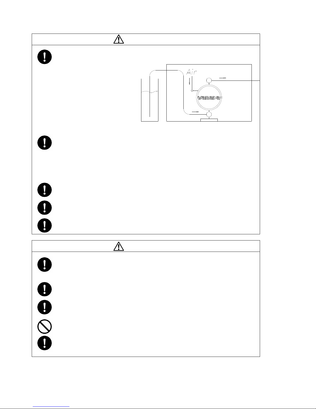
•If a diaphragm of this product is damaged, supply air may mix with the fluid or the fluid may flow
into the main body (air-switching portion). If air supply is inadequate or contaminated, do NOT
operate the pump.
•While operating this product, do NOT cover the intake port by hand.
•If more than two years have elapsed since this product was shipped from the factory, notify your
dealer or our regional office, and do NOT operate it without assurance from the dealer or our
regional office that the pump may be operated safely.
6
Page 7
Table of contents
Table of contents
Table of contentsTable of contents
····Declaration of Conformity
Declaration of Conformity
Declaration of ConformityDeclaration of Conformity
····Introduction
Introduction
IntroductionIntroduction
····For safe operation
For safe operation
For safe operationFor safe operation
····Warnings and caution
Warnings and cautionssss
Warnings and cautionWarnings and caution
····Operating caution
Operating caution
Operating cautionOperating caution
····Table of contents
Table of contents
Table of contentsTable of contents
1. Names of parts and materials
1. Names of parts and materials
1. Names of parts and materials1. Names of parts and materials
1.1 NDP-5 series··········································································8
1.2 DP-10/12 series ······································································9
1.3 NDP-10/12 series ·································································· 10
1.4 NDP-15 series ······································································ 11
1.5 NDP-20, 25 series ································································· 12
1.6 NDP-40 series ······································································ 14
1.7 NDP-50 series ······································································ 15
1.8 NDP-80 series ······································································ 16
1.9 DP-F series·········································································· 17
2. Assembly
2. Assembly
2. Assembly2. Assembly
2.1 Installation of accessories ········································· ············· 18
3. Installation
3. Installation
3. Installation3. Installation
3.1 Method of transport················································· ············· 19
3.2 Installing the pump················································· ············· 19
3.3 Connecting the ground wire ······································ ············· 21
3.3.1. Use in potentially explosive atmospheres·················· ············· 21
4. Connection
4. Connection
4. Connection4. Connection
4.1 Connecting fluid piping ············································ ············· 23
4.2 Connecting air piping ·············································· ············· 24
5. Operation
5. Operation
5. Operation5. Operation
5.1 Method of operation················································· ············· 25
5.2 Flow adjustment····················································· ············· 25
5.3 Shutdown······························································ ············· 26
5.4 Releasing the pressure ············································· ············· 26
6. Method of cleaning
6. Method of cleaning
6. Method of cleaning6. Method of cleaning
7. Daily check
7. Daily check
7. Daily check7. Daily check
8. Troubleshooting
8. Troubleshooting
8. Troubleshooting8. Troubleshooting
8.1 Pump does not run ·················································· ············· 28
8.2 Pump runs, but fluid does not come out ······················· ············· 28
8.3 Flow (discharge quantity) decreased ··························· ············· 28
8.4 Liquid leakage from exhaust port (silencer)·················· ············· 29
8.5 High air consumption during in operation···················· ············· 29
8.6 Irregular noise ······················································· ············· 29
8.7 Irregular vibration ·················································· ············· 29
9. Returning the produ
9. Returning the product for servicing
9. Returning the produ9. Returning the produ
9.1 How to use the FAX sheet········································· ············· 29
9.2 Before returning the product ····································· ············· 29
10. Main body specifications
10. Main body specifications
10. Main body specifications10. Main body specifications
10.1 Main specifications ················································ ············· 30
10.2 Appearance and dimensions ···································· ············· 36
10.3 Performance curve················································· ············· 52
11. Trouble
11. Trouble----Reporting FAX Sheet
11. Trouble11. Trouble
12. Warning s
12. Warning symbols
12. Warning s12. Warning s
13.
13. Limited warranty
Limited warranty
13.13.
Limited warrantyLimited warranty
················································································3
·······································································3
·······································································6
·········································································7
············································ ·········28
Reporting FAX Sheet
Reporting FAX SheetReporting FAX Sheet
ymbols
ymbolsymbols
····························································2
································································4
···································· ·········27
ct for servicing
ct for servicingct for servicing
························ ·········
····································· ·········
···································· ·········
58
59
60
7
Page 8
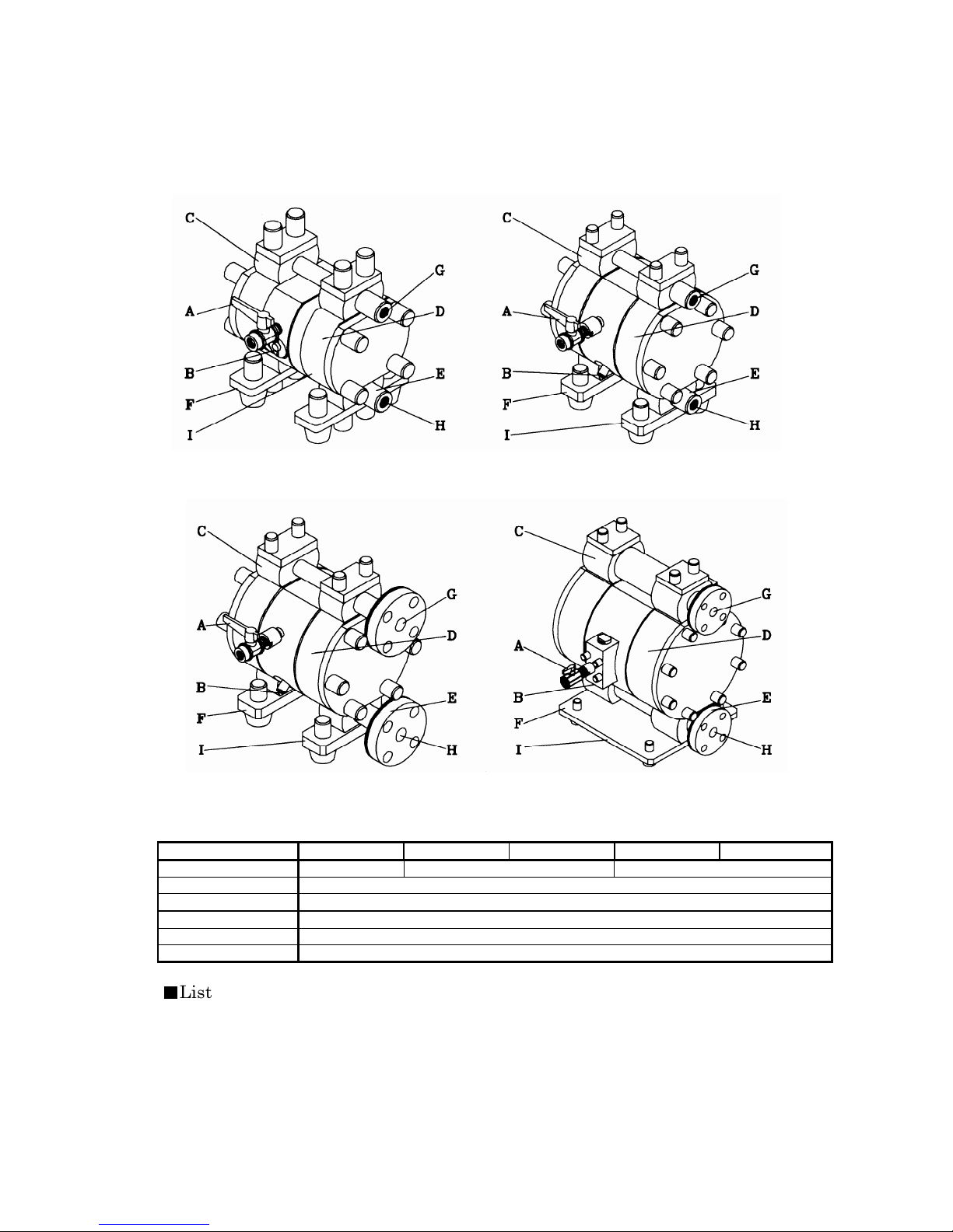
1. Names of parts and materials
E: In Manifold
1. Names of parts and materials
1. Names of parts and materials1. Names of parts and materials
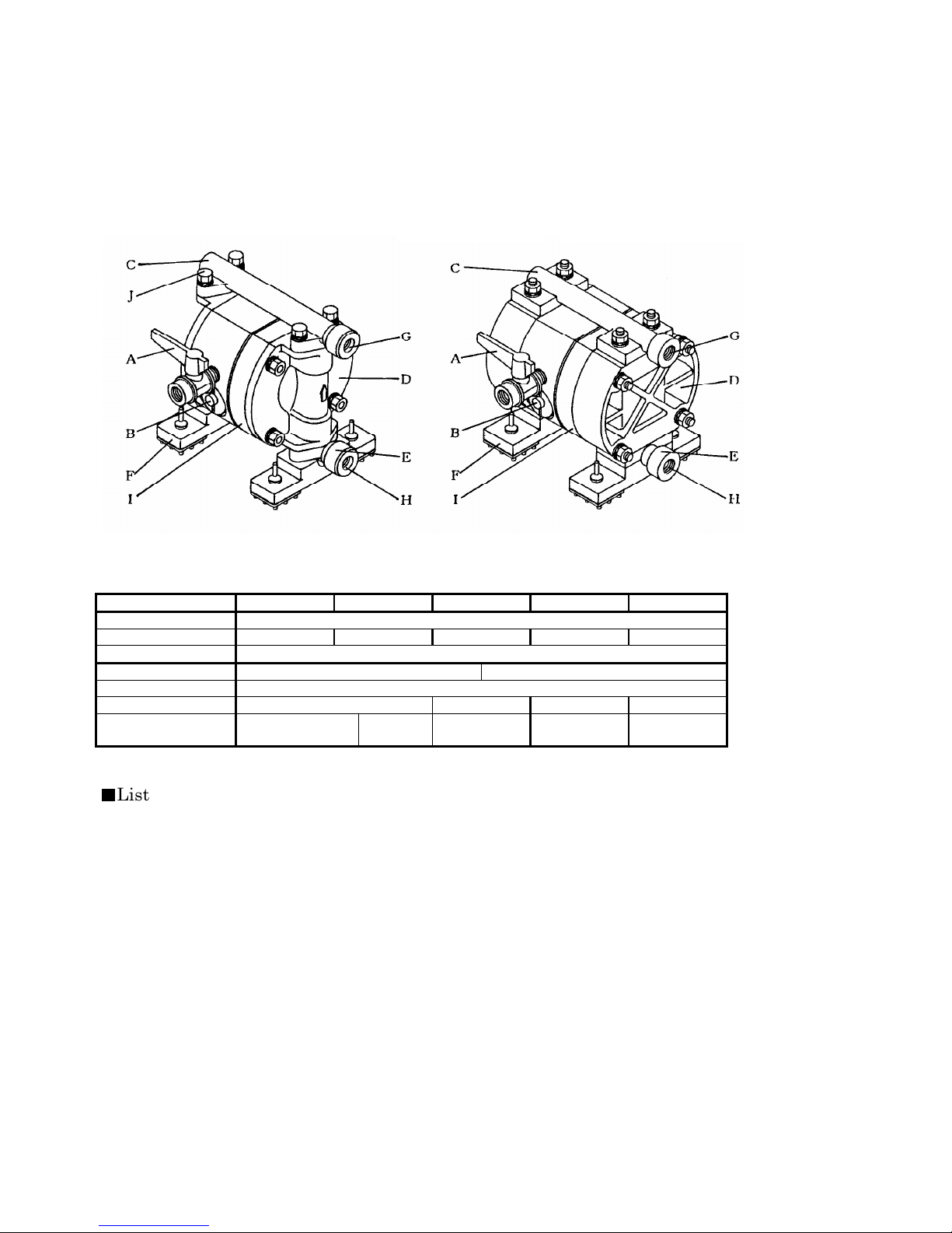
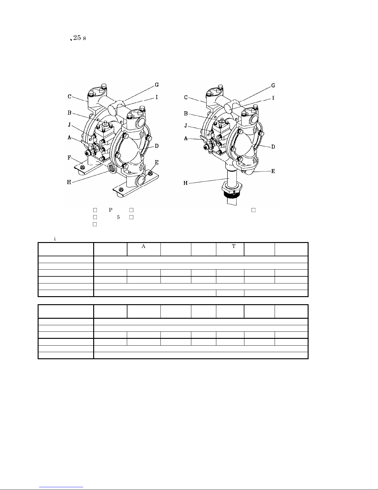
1.1 NDP
1.1 NDP----5 series
1.1 NDP1.1 NDP
NDP-05-FAT NDP-05-FPT
NDP-05-FST NDP-05-FVT
NDP-05-FDT
Switching Portion PPS
Fluid contact Portion AC4C-T6 SCS14 PPG PVDF ACETAL
*Only PTFE diaphragm is setup in NDP-5 series.
■■■■
List of accessories
List of accessories
List of accessoriesList of accessories
•Operation Manual ························ 1
•Maintenance Manual ·· ··· ··· ··· · ··· · 1
•Air Valve·· ·· ·· ·· · ·· ·· ·· ·· ··· ·· ·· ·· ·· 1
•Accessory Tool······························ 1 (FPT, FVT, FDT: 2)
5 series
5 series5 series
A: Air Valve
B: Reset Button
C: Out Manifold
D: Out Chamber
Type FAT FST FPT FVT FDT
Diaphragm PTFE
Flat Valve SUS316 PTFE
O Ring PTFE
Valve Seat SUS316 PPG PVDF ACETAL
Center Disk A5056 SUS316 PPG
(SUS304)
F: Pump Base
G: Discharge Port
H: Intake Port
I: Lift Point
J: Ground Connection Point
PVDF
(SUS304)
ACETAL
(SUS304)
8
Page 9
1111.2
.2 DP
DP----10
10/12
/12 series
.2.2
DPDP
DP-10/12BA□ DP-10/12BS□ DP-10/12BP□ BDP-10/12BA□
•Aluminum type ([ ]: Drum type BBBB)
series
1010
/12/12
series series
A: Air Valve
B: Reset Button
C: Out Manifold
D: Out Chamber
E: In Manifold
Type BAC BAN BAT BAH BAS BAE
F: Pump Base
G: Discharge Port
H: Intake Port
I: Lift Point
J: Ground Connection Point
BDP-10/12BS□
Switching Portion ADC12
Fluid contact Portion
Diaphragm CR NBR PTFE TPEE TPO EPDM
Ball/O Ring CR/NBR NBR PTFE PTFE EPDM EPDM
Valve Seat A5056
Center Disk A5056
•Stainless-steel type ([ ]: Drum type BBBB)
Type BSC BSN BST BSH BSS BSE
Switching Portion ADC12
Fluid contact Portion
Diaphragm CR NBR PTFE TPEE TPO EPDM
Ball/O Ring CR/NBR NBR PTFE PTFE EPDM EPDM
Valve Seat SUS316
Center Disk SUS316
•Polypropylene type ([ ]: Drum type BBBB)
Type BPC BPN BPT BPH BPS BPE
Switching Portion ADC12
Fluid contact Portion
Diaphragm CR NBR PTFE TPEE TPO EPDM
Ball/O Ring CR/NBR NBR PTFE PTFE EPDM EPDM
Valve Seat CR NBR PPG PPG PPG PPG
Center Disk PPG (SUS304)
■■■■
List of accessories
List of accessories
List of accessoriesList of accessories
•Operation Manual·························1
•Maintenance Manual ·· · ··· ··· ··· ··· 1 •Hexagon Wrench ························· 1
•Air Valve·····································1 •Suction Pipe Set ·························· 1 (only BA□,BS□)
ADC12 [ADC12, SUS304]
SCS14 [SCS14, SUS304]
PPG
•Silencer····································· 1
9
Page 10
1111....3
3 NDP
NDP----10
10/12
/12 series
3 3
NDPNDP
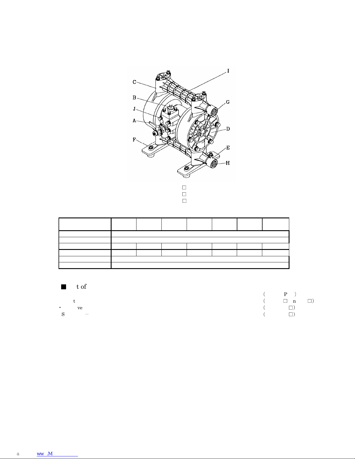
A: Air Valve F: Pump Base
B: Reset Button G: Discharge Port
C: Out Manifold H: Intake Port
D: Out Chamber I: Lift Point
E: In Manifold J: Ground Connection Point
•Polypropylene type
Type BPC BPN BPT BPH BPS BPE
Switching Portion PPS
Fluid contact Portion
Diaphragm CR NBR PTFE TPEE TPO EPDM
Ball/O Ring CR/NBR NBR PTFE PTFE EPDM EPDM
Valve Seat CR NBR PPG PPG PPG PPG
Center Disk PPG (SUS304)
1010
/12/12
series
series series
NDP-10-BPC, NDP-10-BPN
NDP-10-BPT, NDP-10-BPS
NDP-10-BPH, NDP-10-BPE
ADC12
█
List of accessories
List of accessories
List of accessoriesList of accessories
• Operation Manual ·············· 1
• Maintenance Manual ·········· 1
• Air valve··························· 1
• Accessory tool ···················· 1
10
Page 11
1111....4
4 NDP
NDP----15 series
4 4
A: Air Valve F: Pump Base
B: Reset Button G: Discharge Port
C: Out Manifold H: Intake Port
D: Out Chamber I: Lift Point
E: In Manifold J: Ground Connection Point
NDP-15-BA□ NDP-15-FP□
NDP-15-BS□ NDP-15-FV□
NDP-15-FDT
•Aluminum type
Fluid contact Portion
•Stainless-steel type
Fluid contact Portion
•Polypropylene type ([ ]: Polyvinylidene fluoride type, [ ]: Acetal type)
Fluid contact Portion
15 series
NDPNDP
15 series15 series
Type BAC BAN BAT BAH BAS BAE
Switching Portion PPS
ADC12
Diaphragm CR NBR PTFE TPEE TPO EPDM
Ball/O Ring CR/NBR NBR PTFE PTFE EPDM EPDM
Valve Seat A5056
Center Disk A5056
Type BSC BSN BST BSH BSS BSE
Switching Portion PPS
SCS14
Diaphragm CR NBR PTFE TPEE TPO EPDM
Ball/O Ring CR/NBR NBR PTFE PTFE EPDM EPDM
Valve Seat SUS316
Center Disk SUS316
Type FPC FPN FPT/FVT
FDT
Switching Portion PPS
PPG [PVDF] [ACETAL]
Diaphragm CR NBR PTFE TPEE TPO EPDM
Flat Valve/O Ring PTFE/NBR PTFE/NBR PTFE PTFE PTFE/EPDM PTFE/EPDM
Valve Seat PPG [PVDF] [ACETAL]
Center Disk PPG (SUS304) [PVDF (SUS304)] [ACETAL(SUS304)]
FPH FPS/FVS FPE/FVE
■■■■
List of accessories
List of accessories
List of accessoriesList of accessories
•Operation Manual·························1
•Maintenance Manual····················· 1
•Air Valve·····································1
•Accessory Tool······························ 1
11
Page 12
1111.5
.5 NDP
NDP----20
20
、、、、
25 series
.5.5
NDPNDP
A: Air Valve F: Pump Base
B: Reset Button G: Discharge Port
C: Out Manifold H: Intake Port
D: Out Chamber I: Lift Point
E: In Manifold J: Ground Connection Point
NDP-20-BA□, NDP-20-BS□ BDP-20-BA□
NDP-25-BA□, NDP-25-BS□
NDP-25-BF□
•Aluminum type ([ ]: Drum type BBBB)
25 series
2020
25 series25 series
Type BAC BAN
BAE BAV BAT BAS BAH
Switching Portion ADC12
Fluid contact Portion
Diaphragm CR NBR EPDM FPM PTFE TPO TPEE
Ball/O Ring CR/NBR NBR EPDM FPM PTFE EPDM PTFE
Valve Seat SMS1025
Center Disk SUS316 A5056 SUS316
•Stainless-steel type ([ ]: Cast iron type)
Type BSC
[BFC]
Switching Portion ADC12
Fluid contact Portion
Diaphragm CR NBR EPDM FPM PTFE TPO TPEE
Ball/O Ring CR/NBR NBR EPDM FPM PTFE EPDM PTFE
Valve Seat SUS316
Center Disk SUS316
*Cast iron casing is available from NDP-25 series until NDP-80 series.
BSN
[BFN]
ADC12 [ADC12, AC2A, SGP]
BSE
[BFE]
BSV
[BFV]
SCS14 [S45C]
BST
[BFT]
BSS
[BFS]
BSH
[BFH]
12
Page 13
A: Air Valve F : Pump Base
B: Reset Button G: Discharge Port
C: Out Manifold H: Intake Port
D: Out Chamber I: Lift Point
E: In Manifold J: Ground Connection Point
NDP-20BP□
NDP-25BP□
NDP-25BV□
•Polypropylene type ([ ]: Polyvinylidene fluoride type)
Type BPC BPN BPE
[BVE]
Switching Portion ADC12
Fluid contact Portion
Diaphragm CR NBR EPDM FPM PTFE TPEE TPO
Ball/O Ring CR/NBR NBR EPDM FPM PTFE PTFE EPDM
Valve Seat PPG [PVDF]
Center Disk PPG (SUS303) [PVDF(SUS303)]
■■■■
List of accessories
List of accessories
List of accessoriesList of accessories
•Operation Manual·························1 •Bushing·································· 1(only NDP-20)
•Maintenance Manual····················· 1 •Accessory Tool·························· 2(only BP□ and BV□)
•Air Valve·····································1 •Suction Tube···························· 1(only B-BA□)
•Silencer ······································ 1 •Bung adopter Assembly ············· 1(only B-BA□)
BPV
[BVV]
PPG [PVDF]
BPT
[BVT]
BPH BPS
[BVS]
13
Page 14

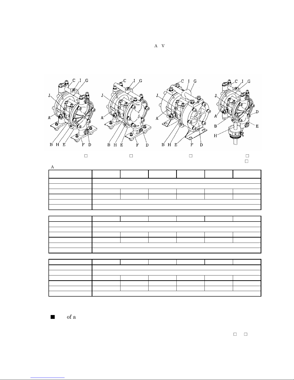
1.6
1.6 NDP
NDP----40
40 series
1.6 1.6
NDPNDP
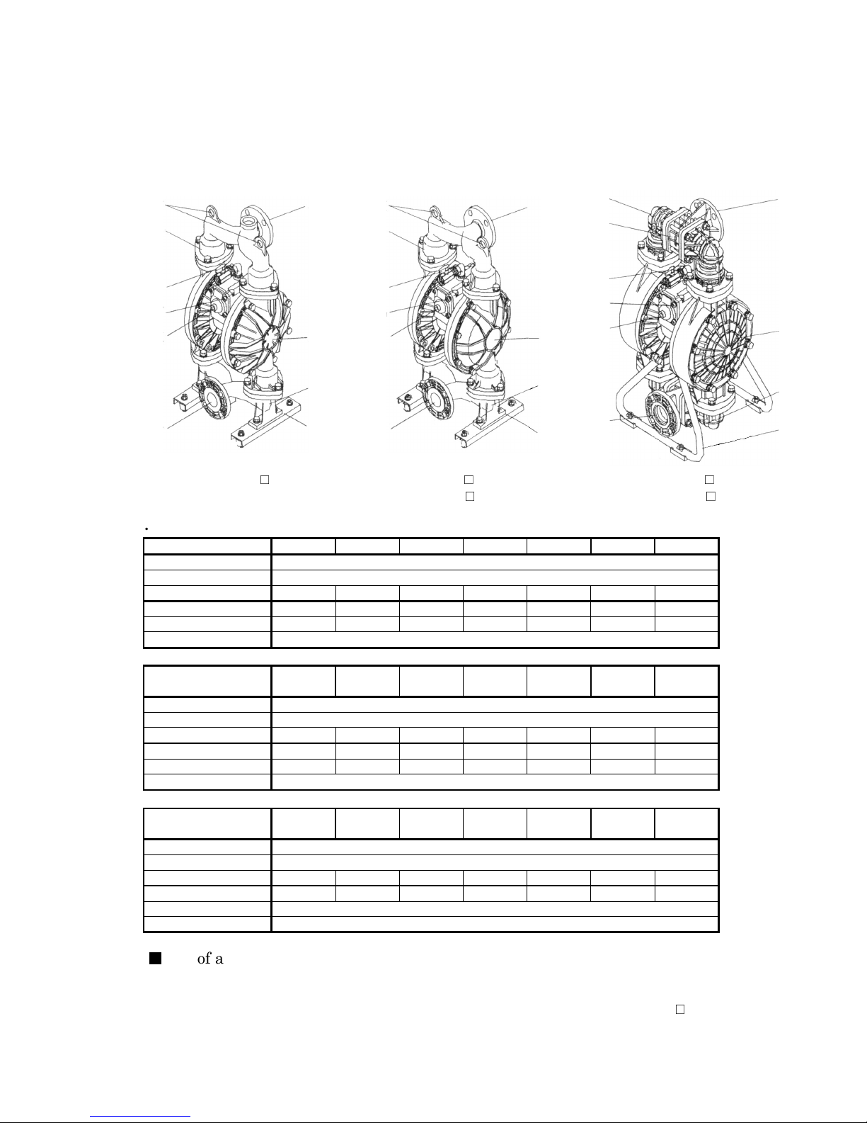
A: Air Valve F : Pump Base (Stand)
B: Reset Button G: Discharge Port
C: Out Manifold H: Intake Port
D: Out Chamber I: Lift Point
E: In Manifold J: Ground Connection Point
I
C
A
J
B D
H
NDP-40BA□ NDP-40BS□ NDP-40BP□
•Aluminum type
Switching Portion ADC12
Fluid contact Portion
Center Disk A5056
•Stainless-steel type ([ ]: Cast iron type)
Switching Portion ADC12
Fluid contact Portion
Center Disk SUS316
•Polypropylene type
Switching Portion ADC12
Fluid contact Portion
Center Disk PPG (SCS13) [PVDF(SCS13)]
■■■■
List of accessories
List of accessories
List of accessoriesList of accessories
•Operation Manual ························ 1
•Maintenance Manual ···················· 1
•Bolt ··········································· 4 (for securing the pump with the cushions, excluding BP□ type.)
series
4040
series series
G
I
G
C
A
J
B D
E
F
Type BAC BAN BAE BAV BAT BAH BAS
Diaphragm CR NBR EPDM FPM PTFE TPEE TPO
Ball/O Ring CR/NBR NBR EPDM FPM PTFE PTFE EPDM
Valve Seat CR NBR EPDM FPM A5056 TPEE TPO
Type BSC
[BFC]
Diaphragm CR NBR EPDM FPM PTFE TPEE TPO
Ball/O Ring CR/NBR NBR EPDM FPM PTFE PTFE EPDM
Valve Seat CR NBR EPDM FPM SUS316 TPEE TPO
Type BPC BPN BPE
Diaphragm CR NBR EPDM FPM PTFE TPEE TPO
Ball/O Ring CR/NBR NBR EPDM FPM PTFE PTFE EPDM
Valve Seat PP / PTFE
H
NDP-40BF□
BSN
[BFN]
BSE
[BFE]
BVE
PPG / PVDF
E
F
ADC12
BSV
[BFV]
SCS14
BPV
BVV
C
I
A
J
B
H
NDP-40BV□
BST
[BFT]
BPT
BVT
BSH
[BFH]
BPH
BVH
BSS
[BFS]
BPS
BVS
F
G
D
E
14
Page 15
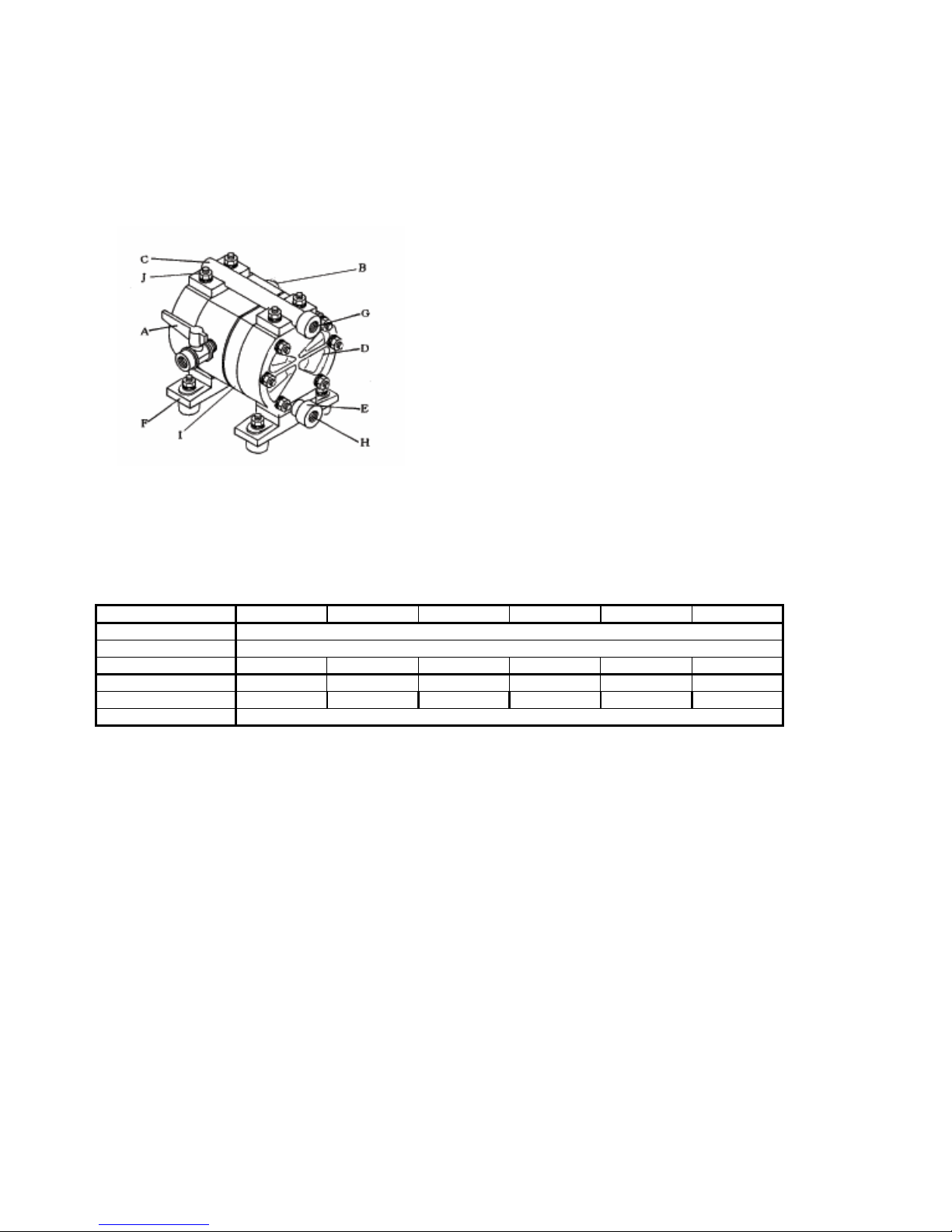
1.7
1.7 NDP
NDP----55550000 series
1.71.7
NDPNDP
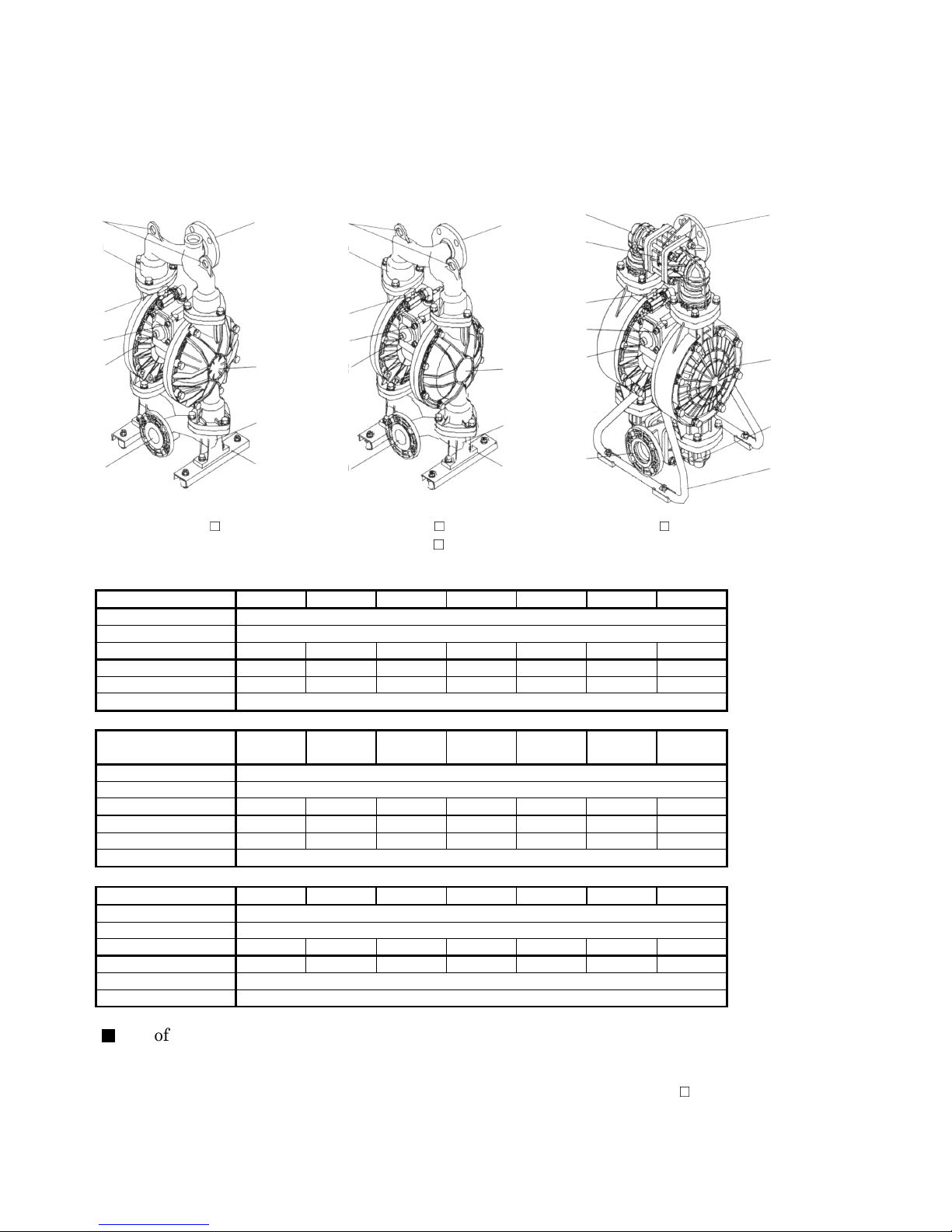
A: Air Valve F : Pump Base (Stand)
B: Reset Button G: Discharge Port
C: Out Manifold H: Intake Port
D: Out Chamber I: Lift Point
E: In Manifold J: Ground Connection Point
I
C
A
J
B
H
NDP-50BA□ NDP-50BS□ NDP-50BP□
•Aluminum type
Switching Portion ADC12
Fluid contact Portion
Center Disk A5056
•Stainless-steel type ([ ]: Cast iron type)
Switching Portion ADC12
Fluid contact Portion
Center Disk SUS316
•Polypropylene type ([ ]: Polyvinylidene fluoride type)
Switching Portion ADC12
Fluid contact Portion
Center Disk PPG (SCS13) [PVDF(SCS13)]
■■■■
List of accessories
List of accessories
List of accessoriesList of accessories
•Operation Manual·························1
•Maintenance Manual····················· 1
•Bolt············································ 4 (for securing the pump with the cushions, excluding BP□ type.)
series
series series
G
I
C
G
C
I
A
A
J
D
E
F
Type BAC BAN BAE BAV BAT BAH BAS
Diaphragm CR NBR EPDM FPM PTFE TPEE TPO
Ball/O Ring CR/NBR NBR EPDM FPM PTFE PTFE EPDM
Valve Seat CR NBR EPDM FPM A5056 TPEE TPO
Type BSC
[BFC]
Diaphragm CR NBR EPDM FPM PTFE TPEE TPO
Ball/O Ring CR/NBR NBR EPDM FPM PTFE PTFE EPDM
Valve Seat CR NBR EPDM FPM SUS316 TPEE TPO
Type BPC BPN BPE
Diaphragm CR NBR EPDM FPM PTFE TPEE TPO
Ball/O Ring CR/NBR NBR EPDM FPM PTFE PTFE EPDM
Valve Seat PP [PTFE]
B D
E
H
NDP-50BF□ NDP-50BV□
ADC12
BSN
[BFN]
BSE
[BFE]
[BVE]
BSV
[BFV]
SCS14 [FC250]
BPV
[BVV]
PPG [PVDF]
F
BST
[BFT]
BPT
[BVT]
J
B D
H
BSH
[BFH]
BPH BPS
BSS
[BFS]
[BVS]
G
E
F
15
Page 16
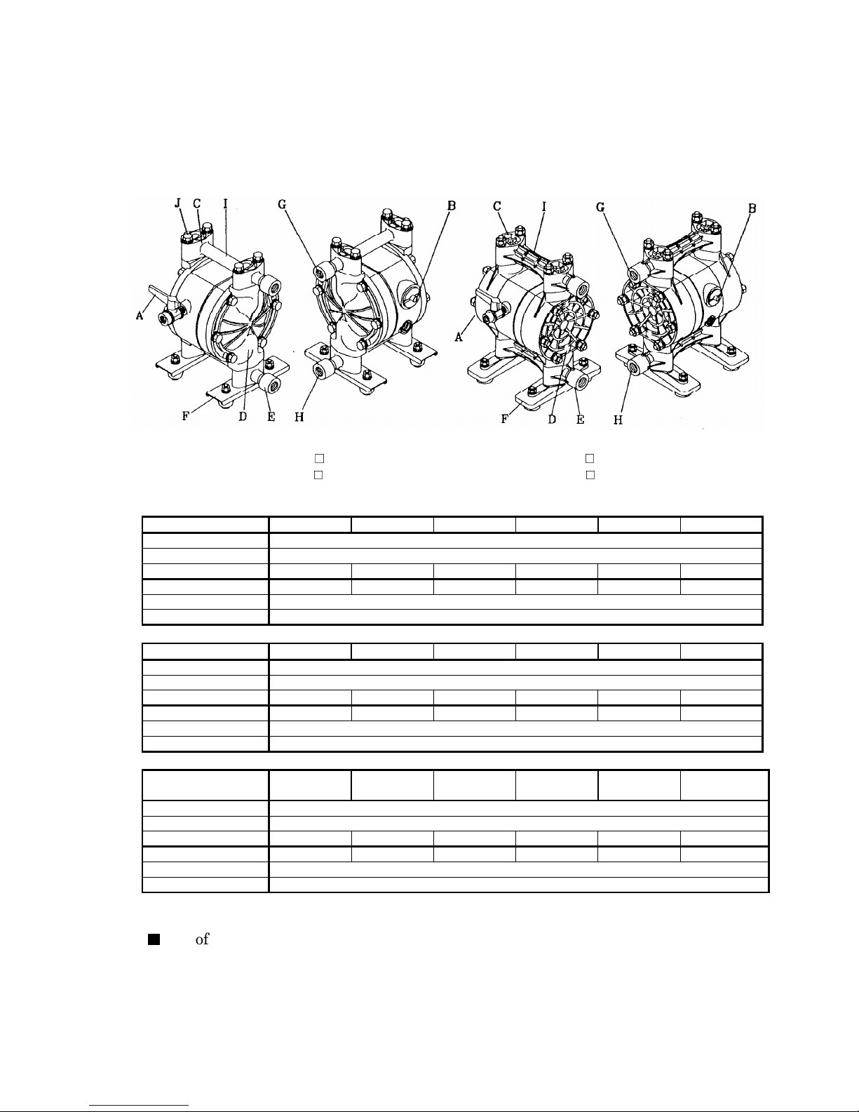
1111.8
.8 NDP
NDP----80 series
.8.8
A: Air Valve F : Pump Base(Stand)
B: Reset Button G: Discharge Port
C: Out Manifold H: Intake Port
D: Out Chamber I: Lift Point
E: In Manifold J: Ground Connection Point
I
C
A
J
B D
H
NDP-80BA□ NDP-80BS□ NDP-80BP□
NDP-80BF□
•Aluminum type
Fluid contact Portion
•Stainless-steel type ([ ]: Cast iron type)
Fluid contact Portion
•Polypropylene type
Fluid contact Portion
■■■■
•Operation Manual ························ 1
•Maintenance Manual ···················· 1
•Bolt ··········································· 4 (for securing the pump with the cushions, excluding BP□ type.)
80 series
NDPNDP
80 series80 series
G
I
G
C
A
J
B D
E
F
Type BAC BAN BAE BAV BAT BAH BAS
Switching Portion ADC12
Diaphragm CR NBR EPDM FPM PTFE TPEE TPO
Ball/O Ring CR/NBR NBR EPDM FPM PTFE PTFE EPDM
Valve Seat CR NBR EPDM FPM A5056 TPEE TPO
Center Disk A5056
Type BSC
[BFC]
Switching Portion ADC12
Diaphragm CR NBR EPDM FPM PTFE TPEE TPO
Ball/O Ring CR/NBR NBR EPDM FPM PTFE PTFE EPDM
Valve Seat CR NBR EPDM FPM SUS316 TPEE TPO
Center Disk SUS316
Type BPC BPN BPE BPV BPT BPH BPS
Switching Portion ADC12
Diaphragm CR NBR EPDM FPM PTFE TPEE TPO
Ball/O Ring CR/NBR NBR EPDM FPM PTFE PTFE EPDM
Valve Seat PP
Center Disk PPG (SCS13)
List of accessories
List of accessories
List of accessoriesList of accessories
H
BSN
[BFN]
ADC12
BSE
[BFE]
E
F
BSV
[BFV]
SCS14
PPG
C
I
A
J
B D
H
BST
[BFT]
BSH
[BFH]
BSS
[BFS]
G
E
F
16
Page 17
1111.9
.9 DP
DP----F series
.9.9
A: Air Valve F : Pump Base
B: Reset Button G: Discharge Port
C: Out Manifold H: Intake Port
D: Out Chamber I: Lift Point
E: In Manifold
DP-5F DP-10F (PT: FEMALE)
DP-20F (PT: FEMALE)
DP-10F (JIS 10K 10A) DP-25F
DP-20F (JIS 10K 20A) DP-38F
•Fluorine resin type
•Operation Manual·························1 •Bushing ························· 1 (only DP-25F)
•Maintenance Manual····················· 1 •Union (Air Port)··············· 1 (exclude DP-5F)
•Air Valve·····································1 •Union (Exhaust Port)········ 1 (only DP-10F, 20F)
•Silencer ······································ 1 (exclude DP-5F) •Reinforcement Plate ········ 8 (only Flange Type)
F series
DPDP
F seriesF series
Type 5F 10F 20F 25F 38F
Switching Portion PPS PP PE, PP
Fluid contact Portion
Diaphragm PTFE
Ball/O Ring PTFE
Valve Seat PTFE
Center Disk PFA (SUS316)
■■■■
List of accessories
List of accessories
List of accessoriesList of accessories
•Accessory Tool ················ 1 (only DP-5F)
PTFE
17
Page 18
2. Assembly
2. Assembly
2. Assembly2. Assembly
2.1 Installation of accessories
2.1 Installation of accessories
2.1 Installation of accessories 2.1 Installation of accessories
1) First, open the product package and make sure that all the accessories are in order (see 1. Names of
parts and materials ■List of accessories after p.8).
2) Attach the air valve and the silencer (nipple) (see the appearance drawings on 1. Names of parts and
materials after p.8).
(With some models, these are already installed.)
CAUTION
CAUTION
CAUTIONCAUTION
•All of the connection parts are capped or taped for shipment. Remove the caps and tapes.
•When installing accessories make sure that no foreign matter falls into the product, as it could
cause malfunction of the switching portion.
•Cover each screw with sealing tape to prevent leakage.
•See 10.1 Main specifications after p.30. Remember that the pump is heavy, so extreme care
must be taken when lifting it.
18
Page 19

3. Installation
3. Installation
3. Installation3. Installation
3.1 Method of transport
3.1 Method of transport
3.1 Method of transport 3.1 Method of transport
•When lifting the pump using a chain hoist or crane before transporting it, be sure to lift it by the
specified lift point (see “1. Names of parts and materials” after p.8).
WARNING
WARNING
WARNINGWARNING
•Be careful that nobody will pass under the pump when you lift it. It would be very dangerous
if the pump should fall.
CAUTION
CAUTION
CAUTIONCAUTION
•See 10.1 Main specifications after p.26. Remember that the pump is heavy, so extreme care
must be taken when lifting it.
•When moving the pump with a forklift or truck, make sure that the pump will not fall. If it does,
it may be damaged and/or cause bodily injury.
•NEVER try to move the pump by pulling the hose connected to the pump. The hose or the pump
may be damaged.
3.2 Installing the pump
3.2 Installing the pump
3.2 Installing the pump 3.2 Installing the pump
1) Decide where the pump should be installed and secure a suitable space
(see Fig. 3.1 A to D).
Note:
Note:
Note: Note:
•Try to keep the suction lift as short as possible.
Protect diaphragm from abnormal breakage, inlet pressure must be
kept below the following values:
*PTFE diaphragm: 0.02MPa (height 2m) During operation
: 0.05MPa (height 5m) Not in operation
*Other diaphragms: 0.1MPa (height 10m)
(Condition with fresh water under ambient temperature)
•Remember to provide sufficient space around the pump for
maintenance.
•Can be changed the direction of the fluid intake port and the discharge
port opposite from each other. (For switching, see the maintenance
manual.)
•The exhaust from the pump will contain some sludge.
When operating the pump where it would have an impact on the
environment, the exhaust should be directed to a place where there will
be no environmental impact.
2) Remove the pump from the package and install it in the designated location.
3) When fixing the pump in place, use the
cushions on the pump base, and secure
pump by tightening the tied-down
bolts a little at a time.
Fig. 3.1
19
Page 20

CAUTION
CAUTION
CAUTIONCAUTION
•Even if you do not use the cushions to secure the pump in place, mount it in such a way
that vibration generated by pump operation will be absorbed.
•If the pump will be submerged during operation, follow the steps below:
*Verify the corrosion resistance of each component of the pump, and do NOT expose the
pump to any fluid for which it does not have proper corrosion resistance.
*Exhaust should direct outside, not into the fluid in which the pump is submerged. For
information on how to arrange the exhaust, see Note: Arranging outside exhaust and
Fig. 3.2 below.
*Make sure that you can reach all of the valves without submerging your hand.
•When operating the pump, operation noise may be generated, depending upon conditions of use
(kind of fluid being pumped, supply air pressure and discharge pressure).
If any regulatory rules apply, provide appropriate acoustic measures. (For the noise level of this
product, see 10.1 Main specifications on p.26.)
•When pumping a hazardous fluid (hot, flammable, strong acid, etc.), provide protective measures
(installation of a pit or sensors, etc.) in consideration of possible leakage of fluid, and post warning
signs at necessary places. For details, see the applicable operating caution on p.4,5 and 6.
WARNING
WARNING
WARNINGWARNING
•If using the pump with a flammable fluid or in a flammable environment read the applicable
operating caution on p.4,5 and 6.
Notes:
Notes:
Notes:Notes:
Fig. 3.2
Arranging outside exhaust
•Remove the silencer.
•Connect a hose with a ground wire to the pumps exhaust port, and
attach the silencer to the tip of the hose. Use a hose of the same
diameter as the exhaust port. (If the hose is longer than 5 meters,
consult your dealer or our regional office.)
•Have a pit, a protection box, etc. at the end of the hose.
•Be sure to have a pit, a protection box, etc. at the end of the hose in preparation for the flow of
fluid in case of damage to a diaphragm. For details, see the applicable operating caution on
p.4,5 and 6.
•Pump exhaust should be directed to a safe place, away from people, animals and food.
WARNING
WARNING
WARNINGWARNING
20
Page 21

3.3 Connecting the ground wire
3.3 Connecting the ground wire
3.3 Connecting the ground wire 3.3 Connecting the ground wire
a) When installing the pump, be sure to connect the
ground wire at the specified position, see relevant
fig. 3.3.
b) Also connect ground wires to peripheral equipment and
piping.
c) Use 2.0mm2 minimum ground wire.
Fig. 3.3.a type 20/25
Position for
connecting the
ground wire
Fig. 3.3.b type 05/10/15 Fig. 3.3.c type dp10 Fig. 3.3.d type 40/50/80
Position for
connecting the
ground wire
Position for
connecting
the ground wire
WARNING
WARNING
WARNINGWARNING
•Be sure to connect ground wires to the connected piping and any other connected equipment.
For details, see the applicable operating caution on p. 4,5 and 6.
When the pump is operated without a ground wire or otherwise not properly grounded,
friction between parts and abrasion caused by some fluids flowing inside the casing may
generate static electricity. Also, depending on the type of fluid being pumped and the
installation environment (such as gases in the air or the surrounding fixtures), it may be a
cause of fire or electric shock.
3.3
3.3.1.
.1. Use in potentially explosive atmospheres
3.33.3
Use in potentially explosive atmospheres
.1..1.
Use in potentially explosive atmospheresUse in potentially explosive atmospheres
1. Your pump can be used in potentially explosive atmospheres if the
symbol of Fig. 3.3.1. is visible on the identification plate. Below the
symbol is indicated what zones and equipment group is applicable.
The maximum allowable surface temperature is indicated on the
type plate Fig. 3.3.2.
2. Always connect a ground wire, which must be attached to
the pump. When removing the pump from the system,
remove the ground wire at last. When installing the pump
to the system, install the ground wire first.
3. Use 2.0mm2 minimum ground wire.
Fig. 3.3.1.
PUMP TYPE
MAX. AIR PRESS. MPa
MODEL NR.
II2GDIIB/IIC 95°C
YE ATEX0580V01X
Fig. 3.3.2.
SERIAL NR.
PROD. YEAR
AQUAMARIJNSTRAAT 50 HENGELO (NL)
21
Page 22

4. The equipment can be used for group II gases (above ground, group I is applicable for mining) in Zones 1 and 2.
For use in combination with group IIC gases, the media must be conductive to prevent built up of static
electricity. For group IIA and IIB gases and for Dust, there are no limitations other than the maximum
allowable media temperature of 95ºC.
5. Make sure that the pump is serviced according to the appropriate service instructions, by a qualified repair
station. Use only original Yamada parts for servicing. Use of non-original parts will make the EX approval
invalid.
6. No modifications or changes to the pump are allowed, this will make the EX approval invalid.
WARNING
WARNING
WARNINGWARNING
•Be sure to connect ground wires to the connected piping and any other connected equipment.
For details, see the applicable operating caution on p.4,5 and 6.
Do not operate the pump without a ground wire or otherwise not properly grounded, friction
caused by some fluids flowing inside the casing may generate static electricity. Also, depending
on the type of fluid being pumped and the installation environment (such as gases in the air or
the surrounding fixtures), it may become an ignition source, resulting in a possible explosion.
•Be careful when using tools at or in the environment of the pump. Dropping of metal objects or
tools on the pump can cause impact sparks, resulting in an explosion if explosive gas is present.
•Make sure that the pump is serviced according to the appropriate service instruction, by a
qualified repair station. Use only original Yamada parts for servicing. Use of non-original parts
will make the EX approval invalid. Doing so can result in dangerous situations, resulting in an
explosion if explosive gas is present.
•No modifications or changes to the pump are allowed, this will make the EX approval invalid.
Doing so can result in dangerous situations, resulting in an explosion if explosive gas is present.
22
Page 23

4. Connection
4. Connection
4. Connection4. Connection
4.1 Connecting fluid piping
4.1 Connecting fluid piping
4.1 Connecting fluid piping 4.1 Connecting fluid piping
1) Connect a flow valve and a drain valve to the fluid discharge port of the pump.
2) Connect a valve for maintenance to the fluid suction intake port of the pump.
3) Connect a hose to the valve on the suction-port side and the valve of the discharge-port side of the pump.
4) Connect a hose on the suction-side intake and the discharge-port side to the respective vessels.
Fig.4.1
CAUTION
CAUTION
CAUTIONCAUTION
•Use a flexible hose to absorb pump vibration, and ground the hose.
•Make sure that there will be no external force on any connection part of the pump.
Be especially careful not to have the pump support part of the weight of the hose and the piping.
•Use a sturdy hose that will not collapse under the strong suction of the pump. Also, make sure
the hose is of more than sufficient pressure rating.
•Use a hose of a diameter the same as or larger than the pump's ports. If you use a hose of
smaller diameter, the pump's performance will be adversely affected, and it may even malfunction.
•When pumping a fluid that contains slurry, verify that the particle size is below the
slurry limitation (after p.30, 10.1 Main specifications).
If it exceeds the limitation of slurries indicated in the main specifications, attach a strainer to
the pump to stop larger particles. Otherwise, such particles may cause a malfunction.
•If, depending upon the place of pump installation, the
volume of the pumped fluid changes drastically, install a
relief valve on the discharge side, and bring the pressure
down below the maximum permissible value. If, owing to
a change in the volume of fluid, the pressure inside the
pump exceeds the maximum permissible pressure, it
may cause damage.
•Keep a vessel below the relief valve to catch any
drain off.
Fig. 4.2
•When testing piping for leakage, do NOT apply pressure to the pump's inlet and outlet sides with
compressed air from outside. It may cause abnormal breakage to the diaphragm or the switching
portion. When testing the piping, either install a valve between the pump's suction inlet and the
discharge outlet and piping, or disconnect the pump from the piping and install plugs so that there
will be no pressure from outside.
•In our product inspection, clean water (pure water for the DP-F series) is used. To prevent mixture
of dirty water into the fluid to be pumped, clean the inside of the pump before finishing installation
work.
•When installing a standby pump or two pumps in parallel, be sure to provide a valve on each of
the IN and OUT sides and perform pump switching by using the liquid material valve. If the
valve of the stop-side pump is open, the diaphragm will be inverted by the discharge pressure of
the operating-side pump, resulting in damage in an early stage.
23
Page 24

4.2 Connecting air piping
4.2 Connecting air piping
4.2 Connecting air piping4.2 Connecting air piping
WARNING
WARNING
WARNINGWARNING
•Before starting work, make sure that the air compressor is shut off.
1) Connect an air valve, air filter, regulator and if necessary lubricator (hereinafter called the
"peripheral equipment") to hose which connected to compressor. Refer (NOTE) for detail information.
2) Install these peripheral items supported by brackets, etc., near the pump.
3) Connect the hose from the peripheral equipment to the air valve of the pump's supply port.
Fig.4.3
CAUTION
CAUTION
CAUTIONCAUTION
•Use a flexible hose to absorb pump vibration, and ground the hose.
•Make sure that there will be no external force on any connection part of the pump.
Be especially careful not to have the pump support part of the weight of the hose and the piping.
•The piping and the peripheral equipment may become clogged with sludge.
Clean the inside of the piping for 10 to 20 seconds before connecting it to the pump.
•Be sure to sufficiently ground the piping and peripheral equipment.
Note:
Note:
Note: Note:
•So that sufficient air can be supplied to meet the needs of the pump, the diameter of the piping should be the
same as the diameter of the supply port of the pump. Also choose peripheral equipment with sufficient airflow
to meet the requirement of air consumption of the pump. Also must be considered usage and stability of air
pressure. Also must be installed it nearest position of pump unit.
•If you use a solenoid valve as the air valve, be sure it is a three-way valve.
When the valve is closed, the internal compressed air of the pump will be released, and this will switch
the spool to its normal position.
•Use of a coupler for the connection part of each hose will make operation and maintenance easier.
•In case of intermitted operation, lubrication is not required during operation. However when pump is
operating by dry air and in case of continuous operation and/or transferring high temperature liquid
(exceeded 70˚C ), lubrication must be required.
Must be used turbine oil none addition class 1 turbine oil (equivalent ISO VG 32 grade) for lubricants.
Adjust lubricator to supply minimum amount of oil to pump unit.
Note: DP-F series are not required lubrication even using dry air.
24
Page 25

5. Operation
5. Operation
5. Operation5. Operation
5.1 Method of operation
5.1 Method of operation
5.1 Method of operation 5.1 Method of operation
CAUTION
CAUTION
CAUTIONCAUTION
•Before starting the pump, make sure that all piping is properly connected.
•Also, before starting the pump, make sure that all the bolts are securely tightened. (Refer
to the maintenance manual for the bolts that a regulation torque is explained.)
•Make sure that the air valve, regulator and the drain valve on the discharge side are closed.
Also, make sure that the valve on the suction side is opened.
1) Start the air compressor.
2) Open the air valve in front of each piece of peripheral equipment, and adjust the supply air pressure
with a regulator to within the permissible range (see 10.1 Main specifications after p.30).
3) Open the flow valve on the discharge side.
4) Press the RESET button, and then slowly open the air valve of the pump.
5) First, verify that fluid is flowing inside the piping and is being pumped to the discharge side, and
then fully open the air valve.
CAUTIO
CAUTIONNNN
CAUTIOCAUTIO
•Do NOT open the air valve suddenly.
•In case of use lubricator, must be used turbine oil none addition class 1 turbine oil (equivalent
ISO VG 32 grade) for lubricants.
Do not apply lubricants more than required and also do not use any other lubricants,
which designated on this instruction manual. This may cause of pump problem and there is
danger of serious bodily damage.
5.2 Flow adjustment
5.2 Flow adjustment
5.2 Flow adjustment 5.2 Flow adjustment
•Adjust the flow valve on the discharge side. For the relationship among the flow,
supply air pressure and discharge pressure, see 10.3 Performance curve after p.52.
•As you start closing the flow valve, the supply air pressure may rise.
Make sure that the pressure is kept within the normal operating range (see 10.1 Main
specifications after p.30).
•Depending upon the viscosity and specific gravity of the fluid, the suction stroke and
other conditions, the permissible suction flow speed of fluid into the pump will vary
however, if the pump speed (flow speed of fluid) increases greatly, cavitations will occur,
and this not only will reduce pump performance, but it may cause a malfunction. Adjust
the supply air pressure as well as the flow in order to prevent cavitations.
•If fluid is not discharged after you start the pump, or if you hear an abnormal noise
or notice any irregularity, shut down the pump immediately (see 8. Troubleshooting after p.28).
CAUTION
CAUTION
CAUTIONCAUTION
25
Page 26

5.3 Shutdown
5.3 Shutdown
5.3 Shutdown5.3 Shutdown
•Close the air valve of the pump and shut off the supply air.
CAUTION
CAUTION
CAUTIONCAUTION
•There is no problem in shutting down the pump with the flow valve closed while air is being
supplied; however, if this condition continues for many hours while there is nobody watching the
pump, it may continue running when there is a leak from the pump or piping, and fluid may
continue flowing out of the position of leakage. Upon finishing your work, release the internal
pressure from the pump and close the air valve (see 5.4 Releasing the pressure).
•When the pump is shut down while pumping slurry, particulate matter contained in the slurry
will be deposited and get stuck inside the out chamber. If the pump is started again as-is,
the diaphragm may be damaged or the center disk may be overloaded, and this may cause
damage such as bending of the center rod. After finishing your work, purge the remaining fluid
from the pump (see 6. Method of cleaning on p.27).
5.4 Releasing the pressure
5.4 Releasing the pressure
5.4 Releasing the pressure 5.4 Releasing the pressure
1) Make sure that the air valve of the pump is closed.
2) Shut down the air compressor or close the valve on the air-supply side of the peripheral equipment.
3) Close the flow valve on the discharge side, start slowly opening the drain valve, and discharge the fluid
under pressure.
4) Open the air valve of the pump and then start running the pump, and discharge the remaining air.
5) After making sure that the pump has been shut down and the pressure has been released, fully open the
regulator, and close the air valve and drain valve of the pump.
CAUTION
CAUTION
CAUTION CAUTION
•Keep a vessel below the relief valve to catch any drain off.
•Fluid under pressure will gush out as soon as you open the valve, so be careful.
•If the pump will be unused for a prolonged period, purge and clean the pump (see the
Operating caution on p.4,5 and 6).
26
Page 27

6. Method of cleaning
6. Method of cleaning
6. Method of cleaning6. Method of cleaning
WARNING
WARNING
WARNING WARNING
•Before starting operation, make sure that compressed air is not supplied to the pump.
•Before starting operation, make sure that the pump is not pressurized.
1) Remove the hose from the suction side of the pump.
2) Close the flow valve on the discharge side, open the drain valve, and then operate a pump by starting air
pressure for a while to discharge any fluid remaining inside the pump as much as possible.
3) Remove the hose from the discharge side, and attach different hoses to the suction side and the discharge
side for cleaning.
4) Be ready with a vessel with cleaning solution, select cleaning solution appropriate for the type of fluid
pumped, and then connect the suction-side and the discharge-side hoses of the pump.
5) Operate a pump by starting air pressure slowly, and let the cleaning solution circulate for sufficient cleaning.
6) Finally, flush with clean water.
7) Remove the hose from the suction side of the pump, run the pump for a while and purge the pump of
remaining fluid as much as possible.
CAUTIO
CAUTIONNNN
CAUTIO CAUTIO
•Be careful when removing piping. Fluid will gush out.
•After cleaning with clean water, turn the pump upside-down to drain out the water.
27
Page 28

7. Daily check
7. Daily check
7. Daily check7. Daily check
•Before starting pump operation, be sure to conduct the following check every day. If any irregularity is
found, do NOT start running the pump until the cause of the irregularity has been found and corrective
measures have been taken.
a) Verify the drain flow through the air filter.
b) In case using a lubricator, verify the quantity of lubricating oil.
c) Make sure that there is no leakage of fluid from any connection part or the pump.
d) Make sure that there are no cracks in the pump casing or piping.
e) Check the tightness of every bolt of the pump.
f) Make sure that the connection parts of the piping and peripheral equipment is not loose.
g) Make sure that the time has not elapsed for replacing any parts of the pump that are to be replaced
at regular intervals. For details, see the maintenance manual.
8. Troubleshooting
8. Troubleshooting
8. Troubleshooting8. Troubleshooting
8.1 Pump does not run
8.1 Pump does not run
8.1 Pump does not run 8.1 Pump does not run
Cause
Cause Act
CauseCause
The exhaust port (silencer) of pump is clogged with
sludge.
Air is not supplied.
The supply air pressure is low.
Air leaks from connection parts. Check the connection parts and tightness of bolts.
Air piping or peripheral equipment is clogged with
sludge.
The flow valve on the discharge side is not open. Open the flow valve on the discharge side.
The spool stopped in neutral position. Press the RESET button.
The fluid piping is clogged with sludge. Check and clean the fluid piping.
The pump is clogged with sludge. Disassemble the casing, check and clean.
8.2 Pump runs, but fluid does not come out
8.2 Pump runs, but fluid does not come out
8.2 Pump runs, but fluid does not come out 8.2 Pump runs, but fluid does not come out
Cause
Cause Action to be taken
CauseCause
The suction lift or discharge head is long. Confirm the piping configuration and shorten the
The discharge-side fluid piping (including the
strainer) is clogged with sludge.
The valve on the suction side is not open. Open the valve on the suction side.
The pump is clogged with sludge. Disassemble the casing, check and clean.
The ball and valve seat are worn out or damaged. Disassemble the manifold, check and replace parts.
8.3 Flow (discharge volume) decreased
8.3 Flow (discharge volume) decreased
8.3 Flow (discharge volume) decreased 8.3 Flow (discharge volume) decreased
Cause
Cause Action to be taken
CauseCause
The supply air pressure is low. Check the compressor and configuration of air piping.
Air piping or peripheral equipment is clogged with
sludge.
The discharge-side flow valve opens differently. Adjust the discharge-side flow valve.
Air is taken in together with fluid. Replenish fluid and check the configuration of the
Cavitations occur. Adjust the supply air pressure and discharge
Chattering occurs. Adjust the supply air pressure and discharge
Icing on air-switching portion. Eliminate ice from air-switching valve and check and
The fluid piping (including the strainer) is clogged
with sludge.
The exhaust port (silencer) of the pump is clogged
with sludge.
The pump is clogged with sludge. Disassemble the casing, check and clean.
Action to be taken
ion to be taken
ActAct
ion to be takenion to be taken
Check and clean the exhaust port and silencer.
Start the compressor, and open the air valve and air
regulator.
Check the compressor and the configuration of air
piping.
Check and clean the air piping.
Action to be taken
Action to be takenAction to be taken
length.
Check and clean the fluid piping.
Action to be taken
Action to be takenAction to be taken
Check and clean the air piping.
suction-side piping.
pressure, and shorten the suction lift.
pressure. Reduce inlet flow valve to adjusting liquid
pressure and volume.
clean the air filter. Use external exhaust hose to
control exhaust air speed. (Refer Fig.3.2)
Check and clean the fluid piping and strainer.
Check and clean the exhaust port and silencer.
28
Page 29

8.4 Liquid leakage from exhaust port (silencer)
8.4 Liquid leakage from exhaust port (silencer)
8.4 Liquid leakage from exhaust port (silencer)8.4 Liquid leakage from exhaust port (silencer)
Ca
Cause
use Action to be taken
CaCa
useuse
The diaphragm is damaged. Disassemble and check the pump and replace the
The fastening nuts for the center disk are loose. Disassemble and check the pump.
8.5 High air consumption during operation
8.5 High air consumption during operation
8.5 High air consumption during operation 8.5 High air consumption during operation
Ca
Cause
use Action to be taken
CaCa
useuse
The seal ring and sleeve are worn out. Disassemble the air-switch portion, check and clean.
8.6 Irregular noise
8.6 Irregular noise
8.6 Irregular noise8.6 Irregular noise
Cause
Cause Action to be taken
CauseCause
The supply air pressure too high. Adjust the supply air pressure.
The spool oscillates, and occurs ball chattering. Adjust the supply air pressure and discharge
The pump is clogged with sludge with particles of
larger than the permissible diameter.
8.7 Irregular vibration
8.7 Irregular vibration
8.7 Irregular vibration 8.7 Irregular vibration
Cause
Cause Action to be taken
CauseCause
The supply air pressure is too high. Adjust the supply air pressure.
The spool oscillates, and occurs ball chattering. Adjust the supply air pressure and exhaust pressure.
Connection parts and pump mounting are loose. Check each connection part and tighten the bolts.
•If disassembly is required, refer to the maintenance manual and follow with the instructions.
•If any of the above mentioned causes do not apply to your problem, contact your dealer or our regional office.
9. Returning the product for servicing
9. Returning the product for servicing
9. Returning the product for servicing9. Returning the product for servicing
9.1 How to use the FAX Sheet
9.1 How to use the FAX Sheet
9.1 How to use the FAX Sheet 9.1 How to use the FAX Sheet
•Copy the FAX Sheet on p.60 "11. Trouble-Reporting FAX Sheet", fills out the necessary details regarding
your problem and conditions of operation, and faxes it to your dealer or our regional office.
9.2 Before returning the product
9.2 Before returning the product
9.2 Before returning the product 9.2 Before returning the product
1) Purge the pump of fluid and clean (see 6. Method of cleaning on p.27).
2) Return the product in the same package as when it was first shipped from the factory.
Action to be taken
Action to be takenAction to be taken
diaphragm.
Tighten the nuts.
Action to be taken
Action to be takenAction to be taken
Replace parts as necessary.
Action to be taken
Action to be takenAction to be taken
pressure. Reduce inlet flow valve to adjusting liquid
pressure and volume.
Disassemble the casing, check and clean.
Action to be taken
Action to be takenAction to be taken
WARNING
WARNING
WARNING WARNING
•It will be the end-user responsibility to thoroughly wash a clean the pumps to prevent
accidents caused by liquid leaks.
CAUTION
CAUTION
CAUTION CAUTION
•Be sure to prevent liquid leak from pump for safe transport.
29
Page 30

10.
10. Main body specification
Main body specification
10.10.
Main body specification Main body specification
10
10....1
1 Main specification
Main specification
1010
1 1
Main specificationMain specification
■■■■
NDP
NDP----5 series
5 series
NDPNDP
5 series5 series
Type
Nominal Diameter
Suction
Connection
Air
Connection
Normal Air Pressure 0.2~0.7MPa (2~7kgf/cm2) 0.2~0.7MPa (2~7kgf/cm2)
Maximum
Discharge Pressure
Discharge Volume/Stroke 20mL
Maximum
Discharge Volume
Maximum
Air Consumption
Slurry Limitation
Limitation of Viscosity
Operating
Ambient
Temperature
Range
Operating Noise 72dB
Weight 1.6kg 2.7kg 1.4kg 1.7kg
Port Fluid
Discharge
Port
Supply
Port
Exhaust
Port
Do not use the flat valve type pump for the liquids with slurry.
Limitation of viscosity is highly dependent on application. Contact your local
distributor or Yamada for more information.
Temp.
Fluid
Temp.
FAT FST FPT FVT FDT
Rc1/4
″
0.7MPa
(7kgf/cm2)
250L/min (ANR) 170L/min (ANR)
0~100˚C
[32~212˚ F ]
NDP-5
1/4˝
(6mm)
E.C. Countries BSP1/4″
Other Countries Rc1/4
Rc1/4˝
Rc3/8˝
0.7MPa
(7kgf/cm2)
11L/min
0~70˚C
[32~158 ˚ F ]
0~60˚C
[32~140 ˚ F ]
■■■■
DP
DP----10
10/12
/12 series
DPDP
Type
Nominal Diameter
Fluid
Connection
Air
Connection
Nominal Air Pressure 0.2~0.7MPa (2~7kgf/cm2) 0.2~0.7MPa (2~7kgf/cm2)
Maximum
Discharge Pressure
Discharge Volume/Stroke 50mL
Maximum
Discharge Volume
Maximum
Air Consumption
Slurry Limitation 1mm or less
Limitation of Viscosity
Operating
Ambient
Temperature
Range
Operating Noise 82dB
Weight 3.6kg [4.5kg]*1 5.3kg [6.2kg]*1 3.1kg
*1.[ ]: Drum type
1010
/12/12
series
series series
Suction /
Port
Discharge
Port
Supply
Port
Exhaust
Port
Temp.
Fluid
Temp.
BA□ BS□ BP□
Rc3/8˝ DP-10 / BSP 1/2˝ DP-12
DP-10/12
3/8˝
(10mm)
E.C. Countries BSP3/8″
E.C. Countries BSP1/2”
Rc3/8˝ DP-10 / BSP 1/2˝ DP-12
Rc1/4˝
Rc 3/8˝
0.7MPa (7kgf/cm2) 0.7MPa (7kgf/cm2)
20L/min 17L/min
300L/min (ANR) 200L/min (ANR)
Other Countries Rc3/8
Limitation of viscosity is highly dependent on application. Contact your local
distributor or Yamada for more information.
0~70˚C
[32~158 ˚ F ]
Diaphragm materials
NBR/CR : 0~70˚C [32~158˚
EPDM : -20~80˚C [1~176˚
TPEE/TPO/PTFE : 0~100˚C [32~212˚
FPM : -10~120 ˚C [14~248˚
F
]
F
]
F
]
F
]
0~60˚C
[32~140 ˚ F ]
″
″
30
Page 31

■■■■
NDP
NDP----10
10/12
/12 series
1010
/12/12
series
series series
Suction
Port Fluid
Discharge
Port
Supply
Port
Exhaust
Port
Temp.
Fluid
Temp.
BPC BPN BPT BPS BPH BPE
NDP-10/12
3/8˝
(10mm)
BSP 3/8” NDP-10
BSP 1/2” NDP-12
Rc1/4˝
Rc3/8˝
0.2 ~ 0.7 Mpa
(7kgf/ cm2 )
0.7 Mpa
(7kgf/ cm2 )
20 L/min
300 L/min (ANR)
Limitation of viscosity is highly dependent on application. Contact your local
distributor or Yamada for more information.
0~70˚C
[32~158˚ F ]
0~60℃
[32~140˚ F ]
NDPNDP
Type
Nominal Diameter
Connection
Air
Connection
Normal Air Pressure
Maximum
Discharge Pressure
Discharge Volume/Stroke 60mL
Maximum
Discharge Volume
Maximum
Air Consumption
Slurry Limitation 1mm or less
Limitation of Viscosity
Operating
Ambient
Temperature
Range
Operating Noise 81dB
Weight 3.3 kg
■■■■
NDP
NDP----15 series
15 series
NDPNDP
15 series15 series
F
]
F
]
F
]
NDP-15
1/2˝
(15mm)
Rc1/4˝
Rc3/8˝
0~70˚C
[32~158˚ F ]
F
]
FVT FDT
E.C. Countries BSP1/2″
Other Countries Rc1/2
0.2~0.7MPa
(2~7kgf/cm2)
0.7MPa
(7kgf/cm2)
0~60℃
[32~140˚ F ]
Type
Nominal Diameter
Suction
Connection
Air
Connection
Normal Air Pressure
Maximum
Discharge Pressure
Discharge Volume/Stroke 70mL
Maximum
Discharge Volume
Maximum
Air Consumption
Slurry Limitation 1mm or less
Limitation of Viscosity
Operating
Ambient
Temperature
Range
Port Fluid
Discharge
Port
Supply
Port
Exhaust
Port
Temp.
Fluid
Temp.
BA□ BS□ FP□
Rc1/2˝
0.2~0.7MPa
(2~7kgf/cm2)
0.7MPa
(7kgf/cm2)
50L/min 45L/min
450L/min (ANR) 350L/min (ANR)
Limitation of viscosity is highly dependent on application. Contact your local
distributor or Yamada for more information.
Diaphragm materials
NBR/CR : 0~70˚C [32~158˚
EPDM : -20~80˚C [1~176˚
TPEE/TPO/PTFE : 0~100˚C [32~212˚
FPM : -10~120 ˚C [14~248˚
Operating Noise 81dB 81dB
Weight 4.1kg 6.2kg 3.5kg 4.3kg
″
31
Page 32

■■■■
NDP
NDP----20 series
20 series
NDPNDP
20 series20 series
Type
Nominal Diameter
Fluid
Connection
Air
Connection
Nominal Air Pressure
Maximum
Discharge Pressure
Discharge Volume/Stroke 350mL 240mL 350mL 240mL 350mL 240mL
Maximum
Discharge Volume
Maximum
Air Consumption
Slurry Limitation 2mm or less
Limitation of Viscosity
Operating
Ambient
Temperature
Range
Suction
Port
Discharge
Port
Supply
Port
Exhaust
Port
Temp.
Fluid
Temp.
BA□
110L/min 100L/min 110L/min 100L/min 110L/min 100L/min
1200L/min
(ANR)
BAT
0.2~0.7MPa
(2~7kgf/cm2)
(7kgf/cm2)
1400L/min
(ANR)
Rc3/4˝
0.7MPa
1200L/min
Suction Lift 5Pa·s or below (5000Cp)
Force In 10Pa·s or below (10.000Cp)
Diaphragm materials NBR/CR : 0~70˚C [32~158˚
EPDM : -20~80˚C [1~176˚
TPEE/TPO/PTFE : 0~100˚C [32~212˚
FPM : -10~120 ˚C [14~248˚
Operating Noise 89dB 89dB
Weight 9.0kg [11.2kg]*1 14.0kg 8.0kg
BS□
(ANR)
NDP-20
3/4˝
(20mm)
Rc1/4˝
Rc3/4˝
1400L/min
0~70˚C
[32~158˚ F ]
BST
(ANR)
F
]
F
F
BP□
E.C. Countries BSP3/4″
Other Countries Rc3/4″
DIN Flange available
0.2~0.7MPa
(2~7kgf/cm2)
0.7MPa
(7kgf/cm2)
1000L/min
(ANR)
]
]
F
]
0~60˚C
[32~140˚ F ]
*1.[ ]: Drum type
■■■■
NDP
NDP----25 (metal type) series
Type
Nominal Diameter
Connection
Air
Connection
Normal Air Pressure
Maximum
Discharge Pressure
Discharge Volume/Stroke 600mL 500mL 600mL 500mL 600mL 500mL
Maximum
Discharge Volume
Maximum
Air Consumption
Slurry Limitation 3mm or less
Limitation of Viscosity
Operating
Ambient
Temperature
Range
Operating Noise 89dB
Weight 13kg 20kg 20kg
25 (metal type) series
NDPNDP
25 (metal type) series25 (metal type) series
Suction
Port Fluid
Discharge
Port
Supply
Port
Exhaust
Port
Temp.
Fluid
Temp.
BA□
1800L/min
(ANR)
BAT
1600L/min
(ANR)
1800L/min
Suction Lift 5Pa·s or below (5000Cp)
Force In 10Pa·s or below (10.000Cp)
Diaphragm materials NBR/CR : 0~70˚C [32~158˚
EPDM : -20~80˚C [1~176˚
TPEE/TPO/PTFE : 0~100˚C [32~212˚
BS□
0.2~0.7MPa
(2~7kgf/cm2)
(ANR)
NDP-25
1˝
(25mm)
Rc1˝
Rc3/8˝
Rc3/4˝
0.7MPa
(7kgf/cm2)
160L/min
1600L/min
0~70
˚C
[32~158 ˚ F ]
BST
(ANR)
F
]
F
]
F
]
FPM : -10~120 ˚C [14~248˚
F
]
BF□
1800L/min
(ANR)
BPT
1000L/min
(ANR)
BFT
1600L/min
(ANR)
32
Page 33

■■■■
NDP
NDP----25 (plastic type) series
Type
Nominal Diameter
Fluid
Connection
Air
Connection
Nominal Air Pressure
Maximum
Discharge Pressure
Discharge Volume/Stroke 600mL 500mL 600mL 500mL
Maximum
Discharge Volume
Maximum
Air Consumption
Slurry Limitation 3mm or less
Limitation of Viscosity
Operating
Ambient
Temperature
Range
Operating Noise 89dB
Weight 11.0kg 13.5kg
25 (plastic type) series
NDPNDP
25 (plastic type) series25 (plastic type) series
Suction
Port
Discharge
Port
Supply
Port
Exhaust
Port
Temp.
Fluid
Temp.
BP□
BPT
NDP-25
1˝
(25mm)
BV□
BVT
E.C. Countries BSP1″
Other Countries Rc1″
DIN Flange available
Rc3/8˝
Rc3/4˝
0.2~0.7MPa
(2~7kgf/cm2)
0.7MPa
(7kgf/cm2)
150L/min
1400L/min (ANR) 1600L/min (ANR) 1400L/min (ANR) 1600L/min (ANR)
Suction Lift 5Pa·s or below (5000Cp)
Force In 10Pa·s or below (10.000Cp)
0~70˚C
[32~158 ˚ F ]
0~60˚C [32~140 ˚ F ] PP
0~80˚C [32~176˚ F ] PVDF
■■■■
NDP
NDP----40 series
NDPNDP
40 series
40 series40 series
Suction
Port Fluid
Discharge
Port
Supply
Port
Exhaust
Port
Temp.
Fluid
Temp.
BA□
380L/min 340L/min 380L/min 340L/min 380L/min 340L/min 380L/min 340L/min
3500
L/min
(ANR)
BAT
Equivalent to
JIS flange 10K40A
2500
L/min
(ANR)
Diaphragm materials
BS□
0.2~0.7MPa
(2~7kgf/cm2)
0.7MPa
(7kgf/cm2)
3500
L/min
(ANR)
Suction Lift 10Pa·s or below (10.000Cp)
Force In 30Pa·s or below (30.000Cp)
NBR/CR : 0~70˚C [32~158˚
EPDM : -20~80˚C [1~176˚
TPEE/TPO/PTFE : 0~100˚C [32~212˚
FPM : -10~120 ˚C [14~248˚
BST
2500
L/min
(ANR)
NDP-40
BF□
1·1/2″
(40mm)
Rc1/2˝
Rc1˝
3500
L/min
(ANR)
0~70˚C
[32~158˚ F ]
Rc1·1/2˝
F
]
F
]
F
]
F
]
BFT
2500
L/min
(ANR)
BP□/BV□
Equivalent to
JIS flange 10K40A
0.2~0.7MPa
(2~7kgf/cm2)
0.7MPa
(7kgf/cm2)
3000
L/min
(ANR)
0~60˚C [32~140˚ F ] PP
0~80˚C [32~176˚ F ] PVDF
Type
Nominal Diameter
Connection
Air
Connection
Normal Air Pressure
Maximum
Discharge Pressure
Discharge Volume/Stroke 2800mL 1400mL 2800mL 1400mL 2800mL 1400mL 2800mL 1400mL
Maximum
Discharge Volume
Maximum
Air Consumption
Slurry Limitation 7mm or less
Limitation of Viscosity
Operating
Ambient
Temperature
Range
Operating Noise 82dB 82dB
Weight 27kg 43kg 47kg 27kg(PP) 32kg(PVDF)
BPT / BVT
3000
L/min
(ANR)
33
Page 34

■■■■
NDP
NDP----50 series
50 series
NDPNDP
50 series50 series
Type
Nominal Diameter
Fluid
Connection
Air
Connection
Nominal Air Pressure 0.2~0.7MPa (2~7kgf/cm2) 0.2~0.7MPa (2~7kgf/cm2)
Maximum
Discharge Pressure
Discharge Volume/Stroke 4300mL 2100mL 4300mL 2100mL 4300mL 2100mL 4300mL 2100mL 4300mL 2100mL
Maximum
Discharge Volume
Maximum
Air Consumption
Slurry Limitation 8mm or less
Limitation of Viscosity
Operating
Ambient
Temperature
Range
Suction
Port
Discharge
Port
Supply
Port
Exhaust
Port
Temp.
Fluid
Temp.
BA□
Equivalent to JIS flange 10K50A Rc2˝ Equivalent to JIS flange 10K50A
600
L/min
4500
L/min
(ANR)
BAT
580
L/min
5500
L/min
(ANR)
BS□
600
L/min
4500
L/min
(ANR)
BST
0.7MPa
(7kgf/cm2)
580
L/min
5500
L/min
(ANR)
Suction Lift 10Pa·s or below (10.000Cp)
Force In 30Pa·s or below (30.000Cp)
Diaphragm materials
NBR/CR : 0~70˚C [32~158˚
EPDM : -20~80˚C [1~176˚
TPEE/TPO/PTFE : 0~100˚C [32~212˚
FPM : -10~120 ˚C [14~248˚
Operating Noise 82dB 82dB
Weight 36kg 63kg 64kg 37kg 42kg
NDP-50
BF□
600
L/min
4500
L/min
(ANR)
0~70˚C [32~158˚ F ]
F
]
F
]
F
]
BFT
2˝
(50mm)
Rc3/4˝
Rc1˝
L/min
5500
L/min
(ANR)
F
]
580
BP□
600
L/min
5000
L/min
(ANR)
BPT
0.7MPa
(7kgf/cm2)
560
L/min
5000
L/min
(ANR)
0~60˚C [32~140˚ F ] PP
0~80˚C [32~176˚ F ] PVDF
BV□
600
L/min
5000
L/min
(ANR)
■■■■
NDP
NDP----80 series
NDPNDP
80 series
80 series80 series
Suction
Port Fluid
Discharge
Port
Supply
Port
Exhaust
Port
Temp.
Fluid
Temp.
BA□
800L/min 640L/min 800L/min 640L/min 800L/min 640L/min 800L/min 600L/min
6000
L/min
(ANR)
BAT
Equivalent to JIS flange 10K80A Rc3˝
5500
L/min
(ANR)
BS□
0.7MPa
(7kgf/cm2)
6000
L/min
(ANR)
Suction Lift 10Pa·s or below (10.000Cp)
Force In 30Pa·s or below (30.000Cp)
Diaphragm materials NBR/CR : 0~70˚C [32~158˚
EPDM : -20~80˚C [1~176˚
TPEE/TPO/PTFE : 0~100˚C [32~212˚
FPM : -10~120 ˚C [14~248˚
NDP-80
BST
3˝
(80mm)
Rc3/4˝
Rc1˝
5500
L/min
(ANR)
0~70˚C [32~158˚ F ]
L/min
(ANR)
BF□
6000
BFT
5500
L/min
(ANR)
F
]
F
]
F
]
F
]
BP□
Equivalent to JIS flange
10K80A
0.2~0.7MPa
(2~7kgf/cm2)
0.7MPa
(7kgf/cm2)
5500
L/min
(ANR)
L/min (ANR)
0~60˚C
[32~140˚ F ]
Type
Nominal Diameter
Connection
Air
Connection
Normal Air Pressure 0.2~0.7MPa (2~7kgf/cm2)
Maximum
Discharge Pressure
Discharge Volume/Stroke 8500mL 3800mL 8500mL 3800mL 8500mL 3800mL 8500mL 3800mL
Maximum
Discharge Volume
Maximum
Air Consumption
Slurry Limitation 10mm or less
Limitation of Viscosity
Operating
Ambient
Temperature
Range
Operating Noise 81dB 81dB
Weight 62kg 104kg 110kg 64kg
BVT
560
L/min
5000
L/min
(ANR)
BPT
5000
34
Page 35

■■■■
DP
DP----F series
F series
DPDP
F seriesF series
Type DP-5F DP-10F DP-20F DP-25F DP-38F
Nominal Diameter
Suction
Connection
Air
Connection
Normal Air Pressure
Maximum
Discharge Pressure
Discharge Volume/Stroke 13mL 65mL 150mL 400mL 700mL
Maximum
Discharge Volume
Maximum
Air Consumption
Slurry Limitation
Limitation of Viscosity 0.5Pa·s or below 1Pa·s or below 2Pa·s or below 2.5Pa·s or below
Operating
Ambient
Temperature
Range
Operating Noise 71dB 82dB 85dB 88dB 90Db
Weight 3.4kg 7.2kg 15.5kg 40kg 52kg
Port Fluid
Discharge
Port
Supply
Port
Exhaust
Port
Temp.
Fluid
Temp.
1/4˝
(6mm)
Rc1/4˝
10L/min 25L/min 50L/min 90L/min 95L/min
170 L/min (ANR) 250 L/min (ANR) 350 L/min (ANR) 1200 L/min (ANR) 1500 L/min (ANR)
Do not use the
flat valve type
pump for the
liquids with
slurry.
3/8˝
(10mm)
Rc3/8˝
or
Equivalent to
JIS flange 10K10A
Rc1/4˝ Rc3/8˝ Rc1/2˝
Rc3/8˝ Rc3/4˝
0.2~0.5MPa
(2~5kgf/cm2)
0.5MPa
(5kgf/cm2)
1mm or less 2mm or less 3mm or less
3/4˝
(20mm)
Rc3/4˝
or
Equivalent to
JIS flange 10K20A
0~70˚C
[32~158˚ F ]
0~80˚C
[32~176˚ F ]
1˝
(25mm)
Equivalent to
JIS flange
10K25A
0.2~0.7MPa
(2~7kgf/cm2)
0.7MPa
(7kgf/cm2)
Equivalent to
1˝
(25mm)
JIS flange
10K25A
35
Page 36

10.2 Appearance and dimensions
10.2 Appearance and dimensions
10.2 Appearance and dimensions10.2 Appearance and dimensions
10.2.1 NDP
10.2.1 NDP----5 series
10.2.1 NDP10.2.1 NDP
■■■■
NDP
NDP----5FAT
NDPNDP
■■■■
NDP
NDP----5FST
NDPNDP
■■■■
NDP
NDP----5FPT/FVT
NDPNDP
10.2.2 DP
10.2.2 DP----10 series
10.2.2 DP 10.2.2 DP
5 series
5 series5 series
5FAT
5FAT5FAT
5FST
5FST5FST
5FPT/FVT/FDT
5FPT/FVT5FPT/FVT
10 series
10 series10 series
/FDT
/FDT/FDT
36
Page 37

10.2.
10.2.2222 DP
DP----10/12
10.2.10.2.
DP DP
■■■■
DP
DP----10
10/12
DPDP
1010
■■■■
DP
DP----10
DPDP
10/12
1010
■■■■
DP
DP----10
DPDP
10/12
1010
10/12 series
series
10/1210/12
series series
/12BA
BA
□□□□
BABA
BS
BSBS
BP
BPBP
□□□□
□□□□
/12/12
/12BS
/12/12
/12BP
/12/12
½" BSP for DP12
½" BSP for DP12
½" BSP for DP12
½" BSP for DP12
½" BSP for DP12
½" BSP for DP12
37
Page 38

■■■■
BBBBDP
DP----10
10/12
/12BA
DPDP
1010
/12/12
■■■■
BBBBDP
DP----10
10/12
DPDP
1010
/12BS
/12/12
10.2.3 NDP
10.2.3 NDP----10
10.2.3 NDP10.2.3 NDP
■■■■
NNNNDP
DP----10
10/12
DPDP
1010
10/12
1010
/12BP
/12/12
BA
□□□□
BABA
BS
□□□□
BSBS
/12 series
series
/12/12
series series
BP
□□□□
BPBP
½" BSP for BDP12
½" BSP for BDP12
½" BSP for BDP12
½" BSP for BDP12
½" BSP for NDP12
½" BSP for NDP12
38
Page 39

10.2.
10.2.4444 NDP
NDP----15 series
10.2.10.2.
NDP NDP
■■■■
NDP
NDP----15BA
NDPNDP
■■■■
NDP
NDP----15B
15BSSSS
NDPNDP
15B15B
■■■■
NDP
NDP----15FP
NDPNDP
15 series
15 series15 series
15BA
15BA15BA
□□□□
15FP
□□□□
15FP15FP
□□□□
/FVT
/FVT/FDT
/FDT
/FVT/FVT
/FDT/FDT
39
Page 40

10.2.
10.2.5555 NDP
NDP----20 series
10.2.10.2.
NDP NDP
■■■■
NDP
NDP----20BA
NDPNDP
■■■■
NDP
NDP----20BS
NDPNDP
■■■■
NDP
NDP----20BP
NDPNDP
20BA
20BA20BA
20BS
20BS20BS
20BP
20BP20BP
20 series
20 series20 series
□□□□
□□□□
□□□□
40
Page 41

■■■■
BBBBDP
DP----20BA
DPDP
20BA
20BA20BA
10.2.
10.2.6666 NDP
10.2. 10.2.
NDP----25 series
NDP NDP
■■■■
NDP
NDP----25BA
NDPNDP
25BA
25BA25BA
■■■■
NDP
NDP----25BS
NDPNDP
25BS
25BS25BS
□□□□
25 series
25 series25 series
□□□□
□□□□
41
Page 42

■■■■
NDP
NDP----25BF
NDPNDP
■■■■
NDP
NDP----25BP
NDPNDP
■■■■
NDP
NDP----25BV
NDPNDP
25BF
25BF25BF
25BP
25BP25BP
25BV
25BV25BV
□□□□
□□□□
□□□□
42
Page 43

10.2.
10.2.7777 NDP
NDP----40 series
10.2.10.2.
NDP NDP
■■■■
NDP
NDP----40BA
NDPNDP
■■■■
NDP
NDP----40BS
NDPNDP
■■■■
NDP
NDP----40BF
NDPNDP
40 series
40 series40 series
40BA
40BA40BA
40BS
□□□□
40BS40BS
40BF
□□□□
40BF40BF
□□□□
43
Page 44

■■■■
NDP
NDP----40
NDPNDP
■■■■
40BP
BP
□□□□
4040
BPBP
NDP
NDP----40BV
40BV
NDPNDP
40BV40BV
□□□□
44
Page 45

10.2.
10.2.8888 NDP
NDP----50 series
10.2.10.2.
NDP NDP
■■■■
NDP
NDP----50B
NDPNDP
■■■■
NDP
NDP----50BS
NDPNDP
50 series
50 series50 series
50BAAAA
50B50B
50BS
□□□□
50BS50BS
□□□□
45
Page 46

■■■■
NDP
NDP----50BF
NDPNDP
■■■■
NDP
NDP----50BP
NDPNDP
■■■■
NDP
NDP----50BV
NDPNDP
■■■■
NDP
NDP----50B
NDPNDP
50BF
50BF50BF
50BP
50BP50BP
50BV
50BV50BV
50BVVVV
50B50B
□□□□
□□□□
□□□□
□□□□
46
Page 47

10.2.
10.2.9999 NDP
NDP----80 series
10.2.10.2.
NDP NDP
■■■■
NDP
NDP----88880B
NDPNDP
80 series
80 series 80 series
0BAAAA
□□□□
0B0B
■■■■
NDP
NDP----80BS
NDPNDP
80BS
80BS80BS
□□□□
47
Page 48

■■■■
NDP
NDP----80BF
NDPNDP
■■■■
NDP
NDP----80BP
NDPNDP
80BF
80BF80BF
80BP
80BP80BP
□□□□
□□□□
48
Page 49

10.2.
10.2.10
10 DP
DP----F series
10.2.10.2.
1010
■■■■
DP
DP----5F
DPDP
■■■■
DP
DP----10F(PT:FEMALE)
DPDP
F series
DP DP
F seriesF series
5F
5F5F
10F(PT:FEMALE)
10F(PT:FEMALE)10F(PT:FEMALE)
■■■■
DP
DP----10F(JIS 10K 10A)
10F(JIS 10K 10A)
DPDP
10F(JIS 10K 10A)10F(JIS 10K 10A)
49
Page 50

■■■■
DP
DP----20F(PT:FEMALE)
20F(PT:FEMALE)
DPDP
20F(PT:FEMALE)20F(PT:FEMALE)
■■■■
DP
DP----20F(JIS 10K 20A)
20F(JIS 10K 20A)
DPDP
20F(JIS 10K 20A)20F(JIS 10K 20A)
■■■■
DP
DP----25F
25F
DPDP
25F25F
50
Page 51

■■■■
DP
DP----38F
38F
DPDP
38F38F
CAUTION
CAUTION
CAUTION CAUTION
・
Due to improvement or modification of products, dimensions are should be changed without prior notice.
Please contact your dealer or our regional office for detailed information.
51
Page 52

10
10....3
3 Performance curve
Performance curve
1010
3 3
Performance curvePerformance curve
Note:
Note: Synthetic pumps can be used at 7Bar depending on
Note: Note:
temperature. The curve right show you this temperature
range for PP, PVDF and Acetal pumps.
All other synthetic types may be used until a max of 5Bar.
Above 60ºC max pressure 5Bar
Above 60ºC max pressure 5Bar
Above 60ºC max pressure 5BarAbove 60ºC max pressure 5Bar
10
10....3333.1 NDP
10
10
10....3333....2222 (B)
1010
.1 NDP----5 serie
1010
.1 NDP.1 NDP
10....3333....2222 DP
1010
DP----10
DP DP
(B)DP
(B)(B)
5 seriessss
5 serie5 serie
10 series
series
1010
series series
DP----10/12
10/12 series
DPDP
10/1210/12
series
series series
10
10....3333....3333 NDP
1010
NDP----11110 series
NDP NDP
0 series
0 series0 series
52
Page 53

10
10....3333....3333 NNNNDP
1010
10
10....3333....4444 NDP
1010
10
10....3333....5555 NDP
1010
DP----10/12
DPDP
NDP----11115 series
NDP NDP
NDP----20
NDP NDP
10/12 series
series
10/1210/12
series series
5 series
5 series5 series
20 series
series
2020
series series
53
Page 54

10
10....3333....6666 NDP
1010
10
10....3333....7777 NDP
1010
NDP----25
NDP NDP
25 series
2525
NDP----40
NDP NDP
series
series series
40 series
series
4040
series series
54
Page 55

10
10....3333....8888 NDP
1010
NDP----50
NDP NDP
10
10....3333....9999 NDP
1010
NDP----80
NDP NDP
50 series
series
5050
series series
80 series
series
8080
series series
55
Page 56

10
10....3333....10
10 DP
1010
1010
DP----FFFF series
DP DP
series
series series
56
Page 57

Note:
Note:
Note:
Method of measurement of operating noise
Note:Note:
With a specified noise meter, the operating noise is measured at measurement points A, B and C, and the
maximum value is to be used.
Note:
Method of measurement of performance curve
Note:Note:
Measuring instruments and procedure
・
Conditions
a) Supplied air pressure: Maintaining preset pressure
b) Liquid pumped: Fresh water
c) Temperature: Ambient
d) Condition of suction: Flat suction 0 meter head
e) Measuring system: System A … Converting weight of discharged fluid to volume.
System B … By liquid meter
57
Page 58

11.
11. Trouble
Trouble----Reporting FAX Sheet
11. 11.
TroubleTrouble
・
Your information will be most helpful in our efforts to improve our servicing as well as checking into causes
of troubles and irregularities. Therefore, take your time, fill out the following FAX sheet and fax it to your
dealer or our regional office. Thank you.
Name of your firm
Address
MODEL/No. (Product name/Product No.)
Period of use
From to
/ /
Operating conditions
□Indoor □Outdoor
Frequency of operation
□Continuous
□Intermittent
Hours / day / week / month
Operating air pressure MPa
Discharge pressure MPa
Discharge volume L/min.
Stroke Suction side m
Discharge side m
Oil lubrication □YES □NO
Condition of pump (nature of problem)
Draw a summary drawing of application
(size, length of piping, and component parts)
Reporting FAX Sheet
Reporting FAX SheetReporting FAX Sheet
Trouble
Trouble----Reporting FAX Sheet
TroubleTrouble
Reporting FAX Sheet
Reporting FAX SheetReporting FAX Sheet
Name of person in charge
Department
Telephone (
Fax
Date of product
SERIAL No.
(Lot No.)
Date of purchase
Name of dealer
Type of fluid pumped
Specific gravity
Viscosity Pa•s
Fluid temperature ˚C / ˚F
Slurry □YES Density wt%
Particulate diameter mm
□NO
) -
( ) -
58
Page 59

12. Warning symbols
12. Warning symbols
12. Warning symbols12. Warning symbols
BEWARE: HIGH TEMPERATURE ELECTRIC SHOCK POISON
FLAMMABLE CORROSION EXPLOSION
General warnings, cautions and
danger notifications
FIRE STRICTLY PROHIBITED
59
Page 60

11113. Limited warranty
3. Limited warranty
3. Limited warranty3. Limited warranty
・
This product is shipped to customers only after meeting strict inspection standards. If an abnormality occurs during
normal operation in accordance with the operating instructions and other operating cautions within the warranty
period (12months after date of purchase) that can be attributed to a manufacturing defect, the defective parts of
this product will be serviced or the product will be replaced free of charge. However, this warranty will not cover
compensation for incidental damage or any malfunction listed below.
1. Warranty period
This warranty will be valid for a period of 12months after the date of purchase.
2. Warranty
If, during the warranty period, any of the material of the genuine parts of this product or the workmanship of
this product is found defective, and is so verified by our company, the servicing cost will be fully born by our
company.
3. Exclusion
Even during the warranty period, this warranty does not cover the following:
(1) Malfunction arising from use of parts other than manufacturer-specified genuine parts
(2) Malfunction arising from misuse or operating errors, or lack of storage or maintenance care
(3) Malfunction arising from use with a fluid that may cause corrosion, inflation or dissolution of the
component parts of the product
(4) Irregularity arising from repair made by other than by our firm, our regional office, dealer or authorized
service personnel
(5) Malfunction arising from modification of the product by other than authorized service personnel
(6) Wear and tear of parts that must be regularly replaced in the course of normal operation, such as
diaphragms, valve seats, balls, air switch sleeve valves and O-rings
(7) Malfunction and/or damage due to transportation, moving or drop page of the product after purchase
(8) Malfunction and/or damage due to fire, earthquake, flood or other major forces.
(9) Malfunction arising from use of compressed air that contains impurities or excessive moisture, or
use of gases or fluids other than the specified compressed air
(10) Malfunction arising from use with a fluid that causes excessive abrasion or use of lubricating oil
other than that specified for this product
Furthermore, this warranty does not cover the rubber parts, or other parts that are subject to wear in
normal operation, used in this product and its accessories.
4. Parts
Parts for this product will be kept available for 5 years after discontinuation of production. Once 5 years have
elapsed after close of production, availability of parts for this product cannot be guaranteed.
YAM
YAMADA
YAMYAM
INTERNATIONAL DEPARTMENT
INTERNATIONAL DEPARTMENT
INTERNATIONAL DEPARTMENTINTERNATIONAL DEPARTMENT
1-3, 1-CHOME, MINAMI MAGOME, OHTA-KU, TOKYO, 143-8504, JAPAN
PHONE: 81-(0)3-3777-0241
FAX: 81-(0)3-3777-0584
E-MAIL: intl@yamadacorp.co.jp
YAMADA
YAMADA
YAMADAYAMADA
AQUAMARIJNSTRAAT 50, 7554 NS HENGELO, THE NETHERLANDSPHONE: 31-(0)-74-242-2032
FAX: 31-(0)-74-242-1055
E-MAIL: company@yamada.nl
ADA
ADAADA
CORPORATION
CORPORATION
CORPORATIONCORPORATION
EUROPE
EUROPE
EUROPEEUROPE
B.V.
B.V.
B.V.B.V.
60
 Loading...