

Page 1
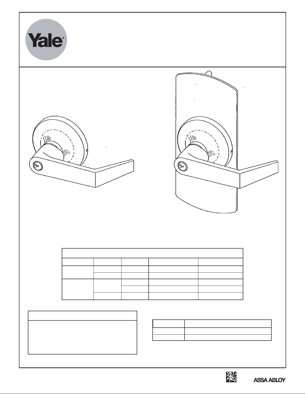
For use with Yale® Series Exit Devices
(Wood and Metal Doors)
540F and 580F
Exit Device Trim
Series
Installation Instructions
541F, 546F, 548F,
& 549F Series Trim
Non-Handed
LEVER TYPE
Key In
Lever
Plain
Lever
*Field Prep: Cut tailpiece off, not to engage the device.
TRIM
541F/581F
546F/586F
548F/588F
549F/589F
FUNCTION
Attention Installer
Any retrofit or other field modification to a fire rated opening can
potentially impact the fire rating of the opening, and Yale Locks &
Hardware makes no representations or warranties concerning what
such impact may be in any specific situation. When retrofitting any
portion of an existing fire rated opening, or specifying and installing
a new fire-rated opening, please consult with a code specialist or
local code official (Authority Having Jurisdiction) to ensure
compliance with all applicable codes and ratings.
All dimensions are in inches (mm) unless otherwise noted.
Sectional Lever Trim
DESCRIPTION
F03 (NL)
F08
Passage
F02
F02
Key retract bolt(s)
Key locks/unlocks lever
Lever retracts bolt(s)
ABBREVIATION
PPHMS
PTHMS
Dummy trim*
Dummy trim
581F, 586F, 588F,
& 589F Series Trim
Non-Handed
REMARKS
Free wheeling lever
Free wheeling lever
Lever always active
Free wheeling lever
Rigid lever
FASTENER DESCRIPTION
PHILLIPS PAN HEAD MACHINE SCREW
PHILLIPS TRUSS HEAD MACHINE SCREW
An ASSA ABLOY Group brand
80-8470-0541-000 (11-12)
Page 2
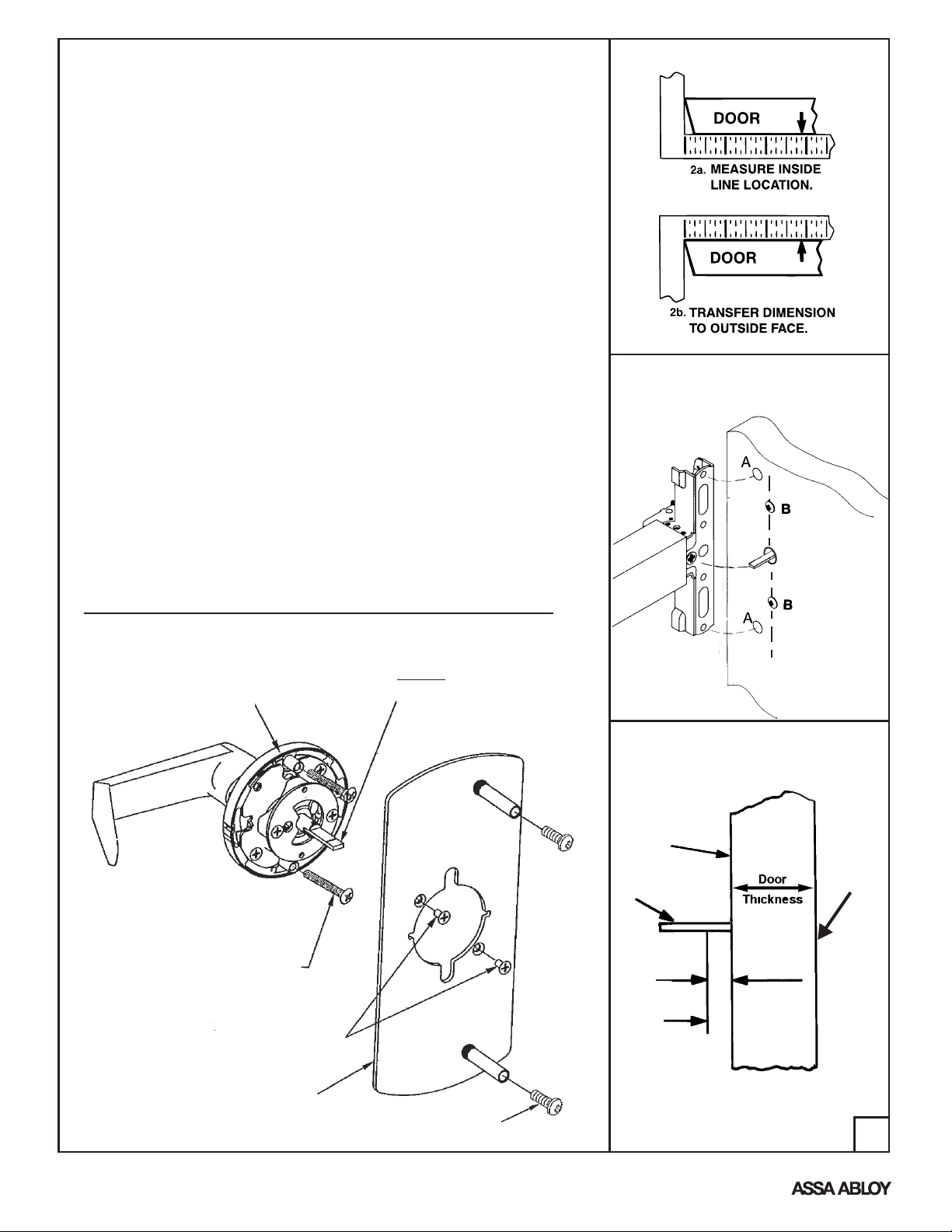
Installation Instructions
1. Check box contents.
2. After marking door inside face for device location (Device
Instructions), transfer “Vertical Reference Centerline” from inside to
outside door face. Follow steps 2a and 2b, at right.
3. Transfer “Horizontal Reference Centerline” from inside to outside door
face.
4. Orient and align trim template, attach with tape to outside door face.
5. Spot holes and prepare door for trim.
6. Adjust trim for door thickness (as reqd).
7. Mount trim to door thru holes “B” with (2) #10-32 x 2" PTHMS
supplied as shown in Fig. 1.
Note: If installing dummy trim, continue as shown in device
instructions.
8. If required, cut trim tailpiece as shown in Fig. 2. Seat device so that
the trim tailpiece penetrates cam slot as shown in Fig. 1. Thru mount
device to trim thru holes “A” as shown in Fig. 1 using 1/4-20 PPHMS
supplied with device.
9. Continue as shown in device instructions.
INSTALLATION INSTRUCTIONS - RHR Shown*
* - Trim Assembly shipped non-handed, rotate assembly
180° for use with LHR application.
Tailpiece
540F Series Trim
For thick door applications use
60-1500-1819. (Ordered Separately)
Secure with pin.
Figure 1
Device is bolted
to trim using
holes “A” (closest
to door lock edge)
Tailpiece (T)
engages with
cross hole of
cam slot.
Cut per Fig. 2
(2) Screws and
washers bolt trim
to door using
holes “B”
Figure 2: Tailpiece Sizing
Device
Mounting
Surface
(See Note)
Trim
Tailpiece
LHR Door
Shown
Trim
Mounting
Surface
Escutcheon Plate Assembly
An ASSA ABLOY Group brand
(2) #10-32 x 2"
Truss Head
Machine Screws
(2) #8-32 Flat Head
Machine Screws
Packed with device.
580F Series Trim
(2) 1/4-20 Pan Head
Machine Screws
5/16
Hold
(8)
Cut Line
NOTE: Measure from device mounting
surface (door face or shim surface)
80-8470-0541-000 (11-12)
2
Page 3

Standard Cylinder
Each 541F and 581F, 548F, and 586F Standard Trim is supplied with
one Yale® 1802 6-pin random keyed cylinder, and (2) keys.
This lever can fit any Yale 6-pin (1802, 5802), or 7-pin (1802A, 5802A)
standard cylinder, or a Schlage lock cylinder using Yale 107S Lever Adapter Kit.
To re-key or exchange any of these cylinders, follow steps 3a or 3b shown below.
Figure 3a. Lever Handle Removable
1. Insert key & rotate clockwise 45°
2. Depress retainer with tool supplied.
3. Slide lever off trim.
Figure 3b. Interchangeable Core Cylinders
Trim levers are specific for the cylinder core used.
Levers are not removable. To remove and install the
cylinder use the control key supplied with the cylinder.
(Reverse steps to re-assemble.)
Lever
Removable
Tool
Adjust lock for door thickness (If necessary)
(Lock is packaged preadjusted for 1-3/4" (44mm) thick doors.)
To adjust for a thicker door.
A. Remove (2) screws from outside rose plate.
B. Slide outside rose away from lock body.
C. Adjust rose plate to desired door thickness per illustration below.
D. Fasten outside rose to lock body with (2) screws.
Figure 4. Cylinder Removal/Exchange
1. Remove retainer pad.
2. Slide cylinder out.
(Reverse steps to reassemble)
Retainer Pad
ROTATED 90°
1-3/4" Door
2" Door
2-1/4" Door
An ASSA ABLOY Group brand
*Sleeve
*S Tailpiece
*Pin
Assembly
Cylinder
Cap
3
Schlage Cylinder
(cap removed)
Cylinder
1802, 1802A
C
5802, 5802A
Spacer
(Omit with 7-pin Cylinder)
107S Lever Adapter Kit
Items marked * are supplied. Schlage
cylinder is not supplied by Yale.
To assemble cylinder:
1. Remove cap and Schlage tailpiece.
2. Install S Tailpiece Assembly. Thread
cylinder cap, allowing for proper plug end
play.
3. Position cam on tailpiece, with cam notch
as shown. Pin in place.
*S Cam
80-8470-0541-000 (11-12)
Page 4

Outside Door
LHR TRIM
Face Trim
Template
3-5/8
(92)
1-3/8
(35)
11/16
(17.5)
X
2-1/8 (54) Dia
x 7/8 (22) Deep
HORIZONTAL
REFERENCE
541F, 546F,
548F, 549F
C
581F, 586F,
588F, 589F
C, X
For Holes Marked “X”
See Below
"
"
"
CAUTION: Office printers, copiers and facsimile
machines may change the size of a drawing and
make the template inaccurate to use as a door
marker. If this is not the original template packed
with the trim, use only the holes on the door (do
not use template as a door marker).
1-3/8
(35)
“C”
(2) 3/8 (9.5) Dia
x 1/2 (13) Deep
7/32 (5.5) Dia Thru
3-5/8
(92)
Dimensions given in
Inches
(mm)
is a
Yale® registered trademark of Yale Security Inc., an ASSA ABLOY Group company. Other products' brand names may be trademarks or registered trademarks of their
respective owners and are mentioned for reference purposes only. These materials are protected under U.S. copyright laws. All contents current at time of publication.
VERTICAL
REFERENCE
CL(Device and Trim)
See Chart
2 "X" HOLES
(for 581F, 586F,
588F, & 589F ONLY)
RHR TRIM
X
Product Support Tel 800. • www.yalelocks.com438.1951
Yale Locks & Hardware is a division of Yale Security Inc., an ASSA ABLOY Group company.
Yale Security Inc. reserves the right to change availability of any item in this catalog, its design, construction, and/or its materials.
All rights reserved. Reproduction in whole or in part without the express written permission of Yale Security Inc. is prohibited.
Copyright © 2004, 2012 Yale Security Inc., an ASSA ABLOY Group company.
4
An ASSA ABLOY Group brand
80-8470-0541-000 (11-12)
 Loading...