

Yaesu FC-700 Instruction Manual
INSTRUCTION
MANUAL
FC-7
YAESU
MUSEN
C.P.O.
BOX
TOKYO,
JAPAN
CO.,
1500
LTD

YAESU
FC-700
ANTENNA
COUPLER
The
FC-700
opération
will
provide a 50-ohm load
System
The
FC-700
scales.
Also included
thé
antenna
also
allows
circuit.
High-quality
it
performs
was
designed.
harmonies
Please
read this manual
FC-700.
is an
on
thé
80
is
within
thé
includes a built-in
for
preliminary coupler adjustments. A THRU
thé
antenna
low-loss
means
The
too,
thus
GENERAL
ultra-compact antenna tuner
through
approximate range
is an
components
thé
inhérent selectivity
reducing
10
meter
amateur bands
to
thé
transceiver when
of 10
ohms
SWR and
internai 50-ohm dummy load, which
to be
connected directly
are
transmitter
in its
can
thé
chance
entirety,
power meter, providing
used
throughout
always
of
"see"
thé
of
harmonic-related
so as to
for
thé
FT-77
(including
thé
feedpoint impédance
to 250
to
FC-700
dérive maximum
ohms.
thé
transceiver,
thé
FC-700.
thé
résistive
matching circuitry
transceiver. Designed
WARC
may be
position
TVI
bands),
of
15
watt
and 150
selected instead
of
thé
bypassing
The
matching function
termination
or
out-of-band émissions.
benefit
for
helps
from
for
thé
FC-700
thé
antenna
watt
of
bandswitch
thé
tuning
which
attenuate
your
it
new
SPECIFICATIONS
Frequency
coverage:
3.5
7
10
14
18
21
24.5
28
Input
impédance:
50
ohms
Max.
variation
approx.
in
load
10-250
Maximum transmitter
150WRF@50ohms
Power
meter
15
W,
150W
calibration
3.5-4.0
7.0-7.5
MHz
MHz
10.0-10.5
14.0-14.5
18.0-18.5
21.0-21.5
24.5-25.0
28.0-29.7
impédance:
ohms
power:
scales:
MHz
MHz
MHz
MHz
MHz
MHz
Insertion
Rear
loss:
0.5 dB
panel
UHF
max.
antenna
type
Dimensions:
238(W)x55(H)x
Weight:
2.0kg
SWRcalibration:
To5:l
SWR
connection:
connecter
180(D)mm
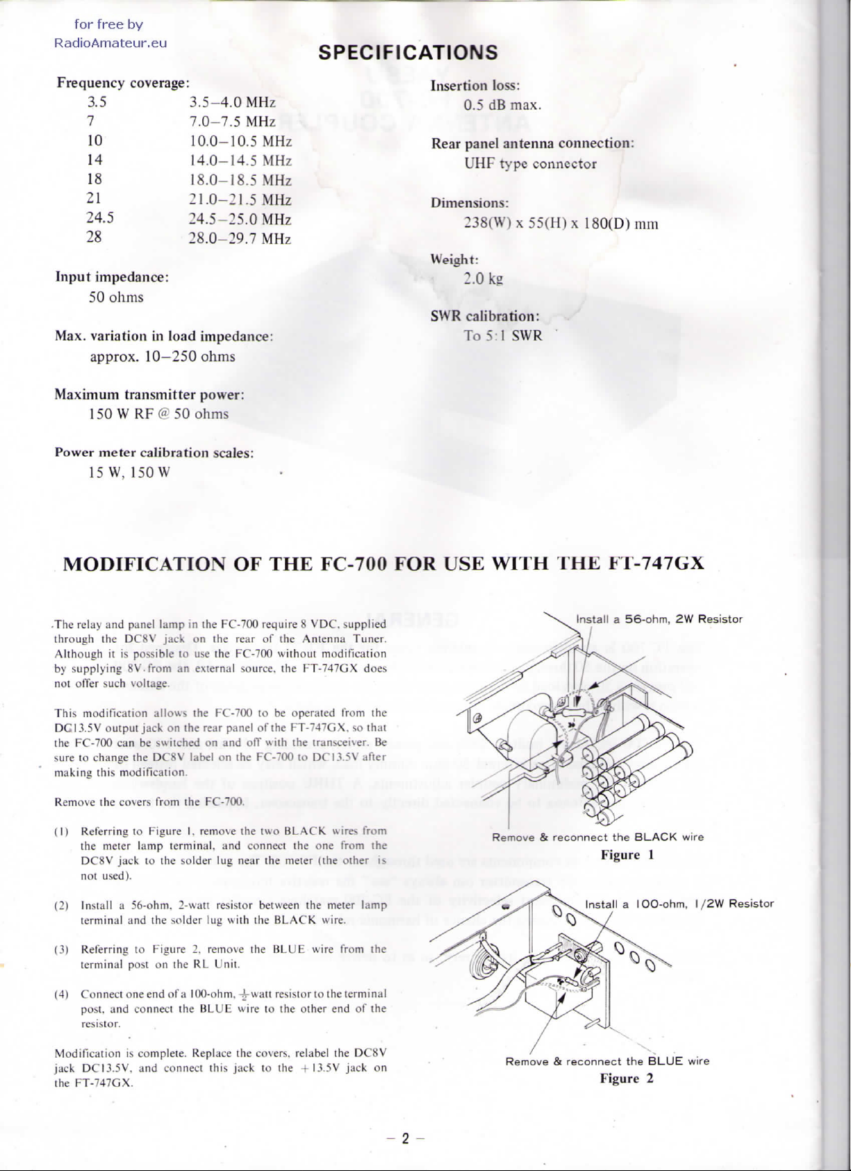
MODIFICATION
The
relay
and
panel
lamp
in
through
thé
DC8V jack
Although
by
not
This modification allows
DG13.5V
thé
sure
making
Remove
(1)
(2)
(3)
it is
possible
supplying
offer
FC-700
to
Referring
Install a 56-ohm.
Referring
8V.
such voltage.
outpui
can be
change
this
modification.
thé
covers
thé
meter lamp
DC8V
jack
not
used).
terminal
and
terminal
post
jack
thé
10
to
to
on
10
from
an
thé
on
thé
switched
DC8V label
from
thé
Figure
I.
terminal,
thé
solder
2-watt
thé
solder
Figure
2,
on
thé
RL
OF THE
(he
FC-700
Ihe
rear
use
thé
FC-700
external
FC-700
rear panel
on and
on
thé
FC-700.
remove
and
lug
resistor
lug
with
remove
Unit.
source,
thé
near
require 8 VDC.
of
thé
without
thé
to be
operated
of Ihe
FT-747GX.
off
with
thé
FC-700
two
BLACK
connect
thé
thé
mêler
between
thé
BLACK
BLUE
thé
FC-700
supplîed
Antenna
FT-747GX
to
thé
Tuner.
modification
from
tran^eiver.
DC13.5V after
wires
one
from
(thé
other
meter lamp
wire.
wire
from
FOR USE
does
thé
so
that
Be
from
thé
is
thé
WITH
Remove & reconnect
IHE
Install a 56-ohm,
FT-747GX
thé
BLACK
Figure
1
Installa
lOO-ohm,
2W
wire
Resistor
I/2W
Resistor
(4)
Connect
post.
and
resistor.
Modification
jack DCI3.5V,
thé
FT-747GX.
one end of a
connecl
is
complète. Replace
and
100-ohm,
thé
connect
4-watt
BLUE wire
thé
this
jack
resistor
to
to
thé
other
covers. relabel
to
thé
+13.5V
thé
terminal
end of
ihe
jack
thé
DC8V
on
- 2 -
Remove & reconnect
Figure
thé
BLUE
2
wire
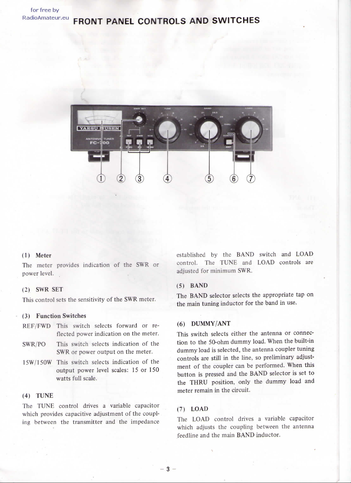
FRONT PANEL CONTROLS
AND
SWITCHES
(1)
Meter
The
meter
power
(2) SWR SET
This
control
(3)
Function
REF/FWD
SWR/PO
15W/150W
(4)
TUNE
The
TUNE control drives a variable capacitor
which
ing
between
provides
level.
sets
Switches
This switch sélects
flected
This
SWR
This
output power
watts
provides capacitive adjustment
thé
indication
thé
sensitivity
power
switch
or
switch
full
transmitter
sélects
power output
sélects
scale.
of
of
thé
forward
indication
indication
on
indication
level
scales:
and
thé
thé
SWR or
SWR
on
thé
thé
meter.
15 or
of
thé
impédance
meter.
or re-
meter.
of
thé
of
thé
150
coupl-
established
control.
adjusted
(5)
BAND
The
BAND selector sélects
thé
main tuning inductor
(6)
DUMMY/ANT
This
switch sélects either
tion
to
dummy
controls
ment
button
thé
THRU
meter remain
(7)
LOAD
The
LOAD
which
feedline
The
for
thé
load
are
of
thé
is
pressed
adjusts
and
by
thé
TUNE
minimum
50-ohm
is
selected,
still
in
coupler
position,
in
thé
control
thé
thé
main
BAND
SWR.
dummy
thé
can be
and
thé
only
circuit.
drives a variable
coupling
BAND inductor.
switch
and
LOAD
thé
appropriate
for
thé
thé
antenna
load.
thé
antenna coupler tuning
line,
so
preliminary
performed.
BAND selector
thé
between
and
controls
band
in
When
dummy
thé
LOAD
are
tap on
use.
or
connec-
thé
built-in
adjust-
When
capacitor
is set to
load
antenna
this
and
- 3 -
 Loading...