

Page 1
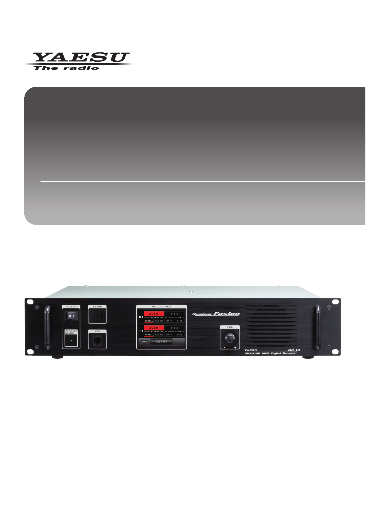
VHF/UHF C4FM/FM
50W AMS DIGITAL REPEATER
DR-1X FR
DR-1XE FR
Operating Manual
Page 2
Contents
About this manual ................................................. 2
Introduction ............................................................ 1
Features of this repeater ..................................... 1
About the touch panel ......................................... 1
Safety Precautions (make sure to read these).... 1
Setting up the Repeater ........................................ 3
Safety measures for installation .......................... 3
Installing the repeater .......................................... 3
About electrical grounding ................................... 3
Connecting Antenna Cables ................................ 4
Connecting the Power Supply ............................. 5
Connecting External Devices .............................. 6
Accessories and Options ..................................... 7
Supplied Accessories .......................................... 7
Optional Accessories ........................................... 7
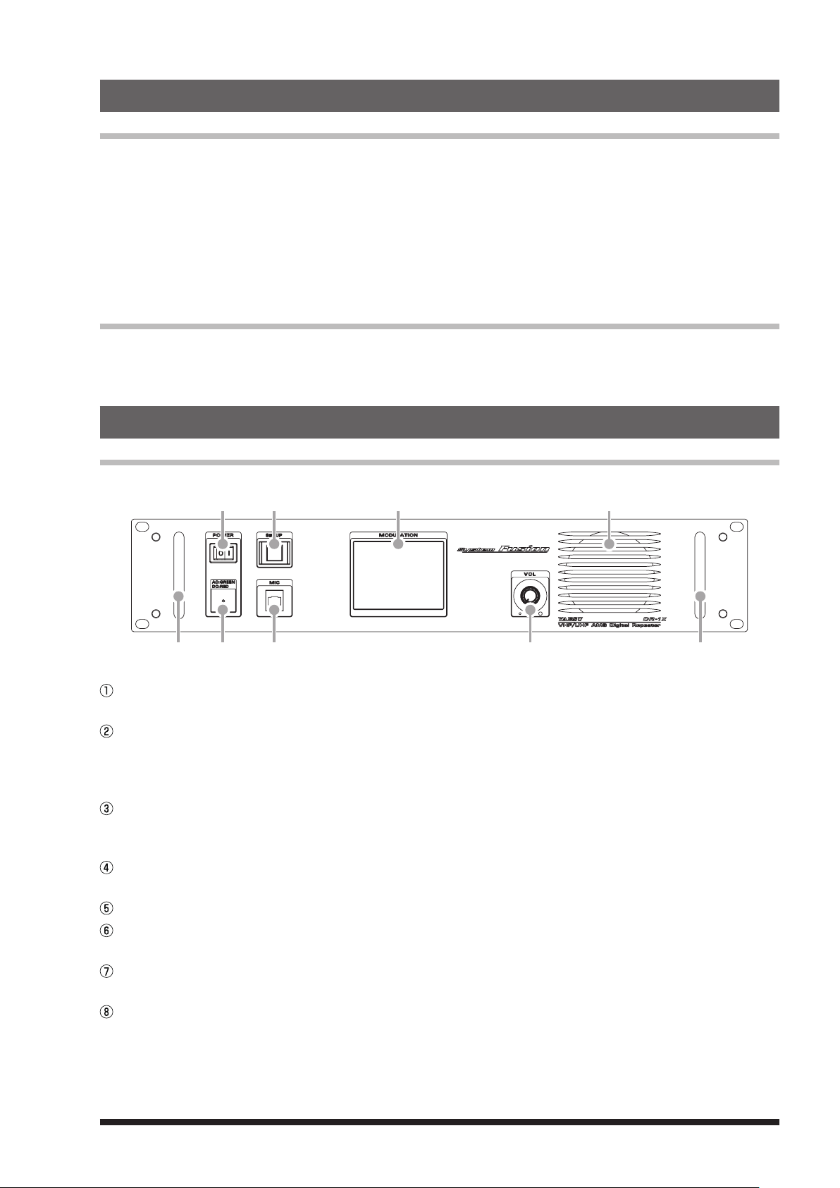
Name and Function of Each Component ............ 7
Front Panel .......................................................... 7
Rear Panel .......................................................... 8
1. Initial set up........................................................ 9
Turn the power on ............................................... 9
Set up the ID (call sign) ....................................... 9
2. Set up Operation Mode ................................... 10
3. Set up Frequency ............................................ 11
4. Set up Other Functions ................................... 12
Adjusting the squelch level ................................ 12
Adjusting the transmit power ............................. 12
Adjusting the volume ......................................... 12
Turning the display ON and OFF ....................... 12
5. Base mode operation ...................................... 13
6. Set up DG-ID Number ...................................... 14
Digital Group Identication (DG-ID) ................... 14
Setting the DG-ID Number ................................ 14
7. Set up DP-ID ..................................................... 16
Digital Personal Identication (DP-ID) ............... 16
Registering the DP-ID ....................................... 16
Delete the registered DP-ID .............................. 17
8. Remote Controls .............................................. 18
Setting the remote control ................................. 18
C4FM DIGITAL CONTROL ................................ 19
ECS (for analog FM mode) ............................... 19
Change the remote command ........................... 20
9. Actual remote control procedure ................... 22
Remote Control for C4FM Digital ...................... 22
Remote Control for Analog FM .......................... 23
10. Set Up Various Functions ............................. 24
Setting the tone signals for analog FM mode .... 25
Setting the TOT (time out timer) ........................ 25
Setting the SQL HYSTERESIS ......................... 25
Setting the SQL TAIL LENGTH ......................... 26
Set the ID announcement for analog FM mode
Set the tone signal type for analog FM mode .... 27
Setting the display turn-off time ......................... 27
Password ........................................................... 27
Setting the half deviation operation ................... 28
Restoring Default Settings (Factory Reset)
11.
12. Connect to the HRI-200 node station ........... 30
13.
Remote Operation with External Controller
Turning remote operation ON/OFF .................... 33
Control from external controller ......................... 33
Setting to connect the
repeater controller S-COM7330 ........................ 36
Connection with S-COM7330 and DR-1X ......... 36
Connecting S-COM7330 ................................... 37
14. Installation of the Optional Accessories ..... 38
Installing the optional Voice Guide Unit FVS-2
15. Specications ................................................ 39
16. After-market Services ................................... 39
YAESU LIMITED WARRANTY .......................... 40
... 26
... 29
... 33
... 38
About this manual
This manual contains symbols and conventions to call attention to important information.
Symbols Description
This icon indicates cautions and alerts the user should be aware of.
This icon indicates helpful notes, tips and information.
About registered trademarks and copyrights
Company and product names described in this manual are trademarks and registered trademarks of their
respective companies.
Unauthorized reproduction or copying of a part or all of the copyrights owned by Yaesu Musen Co., Ltd. in any
form whatsoever is strictly prohibited.
Page 3
Introduction
Features of this repeater
Congratulations on your purchase of the DR-1X Yaesu 144/430MHz Dual Band Dual Receive C4FM/FM Digital
Repeater.
The YAESU DR-1X is a C4FM digital / analog FM dual mode repeater that covers the VHF and UHF amateur
radio bands. DR-1X incorporates the use of Analog FM communication integrated with the C4FM digital
communication through its unique AMS capability.
r The Dual-band repeater is equipped with the VHF and the UHF Amateur radio bands.
r The AMS feature is able to relay both the C4FM and the Analog FM signals.
r The C4FM digital modes may be transferred the GPS information.
r Within the DG-ID feature, only the group members may communicate via the repeater.
r Within the Digital Personal ID (DP-ID) feature, the system manager may control some repeater settings
remotely.
About the touch panel
Precautions in using the touch panel
The touch panel of the controller is designed to work with the slightest touch of a finger.
The touch panel may not work when a protective film or sheet is affixed to the LCD.
Use of a pointed fingernail or pen to operate the touch panel, or pressing too hard may damage or scratch
the screen.
Smart phone operations such as flicking, pinch in and pinch out are not supported.
Safety Precautions (make sure to read these)
Make sure to read this manual in order to use this radio safely and correctly.
Note beforehand that the company shall not be liable for any damages suffered by the customer or third parties in using this product, or for any failures and
faults that occur during the use or misuse of this product, unless otherwise provided for under the law.
Type and meaning of the marks
DANGER
WARNING
CAUTION
Type and meaning of symbols
Prohibited actions that must not be carried out in order to use this radio safely.
For example,
Precautions that must be adhered to in order to use this radio safely. For example,
This mark indicates an imminently hazardous situation, which, if not avoided, could result in death or serious injury.
This mark indicates a potentially hazardous situation, which, if not avoided, could result in death or serious injury.
This mark indicates a potentially hazardous situation, which, if not avoided, may result in minor or moderate injury or only
property damage.
signifies that disassembly is prohibited.
signifies that the power supply is to be disconnected.
DANGER
Do not use the device in “locations or aircraft and vehicles where
its use is prohibited” such as in hospitals and airplanes.
This may exert an impact on electronic and medical devices.
Never touch the antenna during transmission.
This may result in injury, electric shock and equipment failure.
Do not transmit in crowded places in consideration of people
who are fitted with medical devices such as heart pacemakers.
Electromagnetic waves from the device may affect the medical device,
resulting in accidents caused by malfunctions.
Do not operate the device when flammable gas is generated.
Doing so may result in fire and explosion.
Use good engineering, proper grounding and protective devices to
protect the repeater from power surges, lightening and electrical
damage via the power and external antenna connections.
Otherwise when it thunders, immediately disconnect the external
antenna from the repeater and shut OFF the power supply.
If not, fire, electric shock and equipment failure this may result.
Do not touch any liquid leaking from the liquid display with your
bare hands.
There is a risk of chemical burns occurring when the liquid comes into
contact with the skin or gets into the eyes. In this case, seek medical
treatment immediately.
1
Page 4
WARNING
Do not use voltages other than the specified power supply
voltage.
Doing so may result in fire and electric shock.
Do not transmit continuously for long periods of time.
This may cause the temperature of the main body to rise and result
in burns and failures due to overheating.
Do not dismantle or modify the device.
This may result in injury, electric shock and equipment failure.
When smoke or strange odors are emitted from the radio, turn
off the power and disconnect the power cord from the socket.
This may result in fire, liquid leak, overheating, damage, ignition and
equipment failure. Please contact our company amateur customer
support or the retail store where you purchased the device.
Do not place the device in areas that may get wet easily (e.g.
near a humidifier).
This may result in fire, electric shock and equipment failure.
When connecting a DC power cord, pay due care not to mix up
the positive and negative polarities.
This may result in fire, electric shock and equipment failure.
Do not use power cords other than the one enclosed or
specified.
This may result in fire, electric shock and equipment failure.
Do not bend, twist, pull, heat and modify the power cord and
connection cables in an unreasonable manner.
This may cut or damage the cables and result in fire, electric shock
and equipment failure.
Do not pull the cable when plugging and unplugging the power
cord and connection cables.
Please hold the plug or connector when unplugging. If not, this may
result in fire, electric shock and equipment failure.
Do not handle the power plug and connector etc. with wet
hands. Also do not plug and unplug the power plug with wet
hands.
This may result in injury, electric shock and equipment failure.
Keep the power plug pins and the surrounding areas clean at
all times.
This may result in fire, overheating, breakage, ignition etc.
Do not use the device when the power cord and connection
cables are damaged, and when the power connector cannot be
plugged in tightly.
Please contact our company amateur customer support or the retail
store where you purchased the device as this may result in fire,
electric shock and equipment failure.
Do not use fuses other than those specified.
Doing so may result in fire and equipment failure.
Do not allow metallic objects such as wires and water to get
inside the product.
This may result in fire, electric shock and equipment failure.
Disconnect the power cord and connection cables before
incorporating items sold separately or replacing the fuse.
This may result in fire, electric shock and equipment failure.
Follow the instructions given when installing items sold
separately and replacing the fuse.
This may result in fire, electric shock and equipment failure.
Do not use the device when it thunders.
For safety reasons, pull the power plug out of the AC socket.
Never touch the antenna as well. This may result in fire, electric
shock and equipment failure due to thunder.
CAUTION
Do not place this device near a heating instrument or in a
location exposed to direct sunlight.
This may result in deformation and discoloration.
Do not place this device in a location where there is a lot of
dust and humidity.
Doing so may result in fire and equipment failure.
Stay as far away from the antenna as possible during
transmission.
Long-term exposure to electromagnetic radiation may have a
negative effect on the human body.
Do not wipe the case using thinner and benzene etc.
Please use a soft and dry piece of cloth to wipe away the stains
on the case.
Do not put heavy objects on top of the power cord and
connection cables.
This may damage the power cord and connection cables, resulting
in fire and electric shock.
Do not transmit near the television and radio.
This may result in electromagnetic interference.
Do not use optional products other than those specified.
If not, this may result in equipment failure.
Do not place the device on an unsteady or sloping surface, or
in a location where there is a lot of vibration.
The device may fall over or drop, resulting in fire, injury and
equipment failure.
For safety reasons, switch off the power and pull out the power
cord when the device is not going to be used for a long period
of time.
If not, this may result in fire and overheating.
Do not throw or subject the device to strong impact forces.
This may result in equipment failure.
Do not put this device near magnetic cards and video tapes.
The data in the cash card and video tape etc. may be erased.
Keep out of the reach of small children.
If not, this may result in injuries to children.
Do not stand on top of the product, and do not place heavy
objects on top or insert objects inside it.
If not, this may result in equipment failure.
Do not use a microphone other than those specified when
connecting a microphone to the device.
If not, this may result in equipment failure.
Do not touch the heat radiating parts.
When used for a long period of time, the temperature of the heat
radiating parts will get higher, resulting in burns when touched.
Do not open the case of the product except when replacing the
fuse and when installing items sold separately.
This may result in injury, electric shock and equipment failure.
2
Page 5
Setting up the Repeater
Safety measures for installation
Note the following precautions when installing this repeater:
Use good engineering, proper grounding and protective devices to protect the repeater from power surges,
lightening and electrical damage via the power and external antenna connections.
Do not install the repeater in a place where there is extreme vibration, where there is a lot of dust, excessive
humidity or high temperature, or where it is exposed to direct sunlight.
Install the repeater in a well ventilated position, so heat dissipation is not obstructed. The heat sink becomes
hot when transmitting for long periods of time.
Do not place any objects on top of the repeater.
Note that there is a risk that hum and noise may be introduced, depending on the installation conditions and
the external power source used.
Installing the repeater
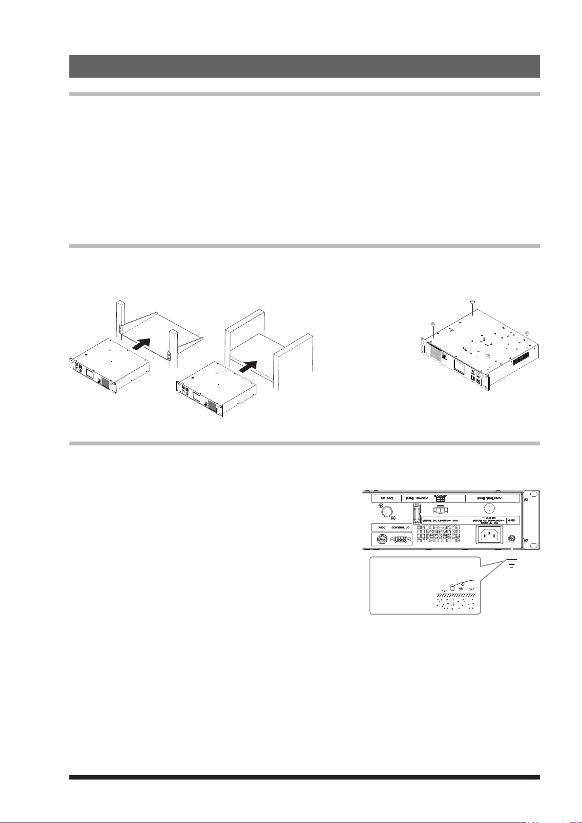
Place the repeater on a flat and level rack or shelf, with its bottom side down. We recommend securing the
wings of the repeater front panel to the equipment rack or shelf with bolts.
z Mounting on rack or shelf
z Mounting on a desk
When using the repeater in a desktop location instead of a rack
or shelf, attach the four
supplied legs onto the
bottom of the repeater
case.
About electrical grounding
The DR-1X repeater, like any other communications apparatus, requires an effective ground system for
maximum electrical safety and best communications effectiveness. A good ground system can contribute to
station efficiency in a number of ways:
• It can minimize the possibility of electrical shock to the operator.
• It can minimize RF currents flowing on the shield of the coaxial
cable and the chassis of the repeater. Such currents may lead to
radiation, which can cause interference to home entertainment
devices or laboratory test equipment.
• It can minimize the possibility of erratic repeater/accessory
operation caused by RF feedback and/or improper current flow
through logic devices.
To prevent damage from lightning,
atmospheric electricity, electrical shock,
etc., provide a good earth ground.
Use a short, thick, braided
cable to connect your
station equipment to
the buried ground rod
(or alternative earth
ground system).
The figure above shows the rear panel of the DR-1X.
3
Page 6
Connecting Antenna Cables
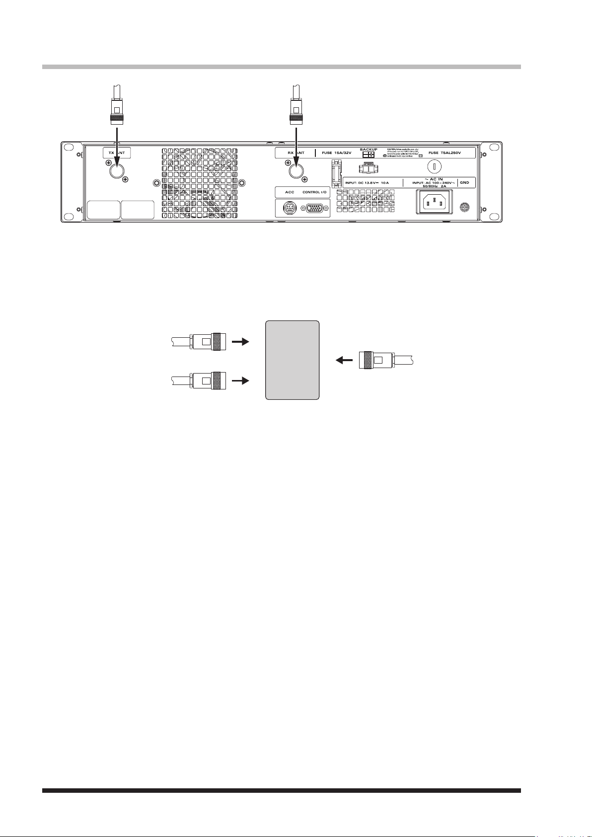
From RX ANT
Duplexer
The figure above shows the rear panel of the DR-1X.
1 When using a duplexer, plug the coaxial cables from the TX ANT and RX ANT terminals into the jacks of the
duplexer, and tighten the connectors.
2 Plug in the terminal of the coaxial cable connected to the antenna into the jack of the duplexer, and turn to
tighten.
From TX ANT
To antenna
4
Page 7
Connecting the Power Supply
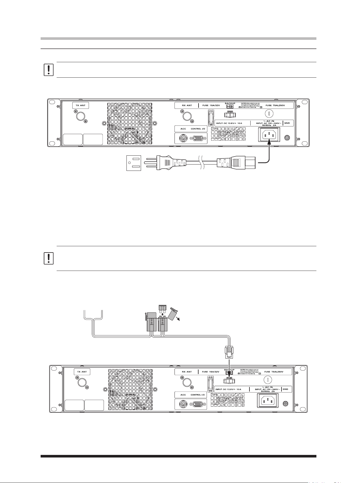
Fuse (15 A)
Connection for DR-1X (US and Asian versions)
z Main power
Use an AC outlet capable of supplying AC 100-240V at 50 or 60Hz.
1 Insert the socket of the provided AC power cord into the AC IN jack at the rear of the repeater.
2 Insert the plug of the provided AC power cord into the AC outlet.
z Backup power
For uninterrupted operation during power failures, a 13.8V rechargeable automotive type battery (55-Ah or
more recommended) may be connected to the BACKUP terminal posts on the rear panel. In the event of
an AC power outage, the automatic power control circuit will switch the repeater to the backup battery, and
operation will not be interrupted.
While operating from a battery or DC supply, the repeater requires approximately 14A at 13.8V during
transmit.
Always observe proper polarity when making DC connections.
z Use a power source capable of supplying DC 13.8V and a current capacity of 14A or more.
z Make sure to switch OFF the power of the external power source before connecting.
z If the transmit power is set to “HI” (50W), the transmit power is automatically set to “MD” (20W) when operation is
switched to the backup power supply.
1 Insert the connector of the provided DC power cord into the BACKUP jack at the rear of the repeater.
2 Connect the red wire (+) of the provided DC power cord to the positive (+) terminal of the external power
source, and the black wire (-) to the negative (-) terminal.
(black)
–
+
(red)
5
Page 8
Connection for DR-1XE (European and Australian versions)
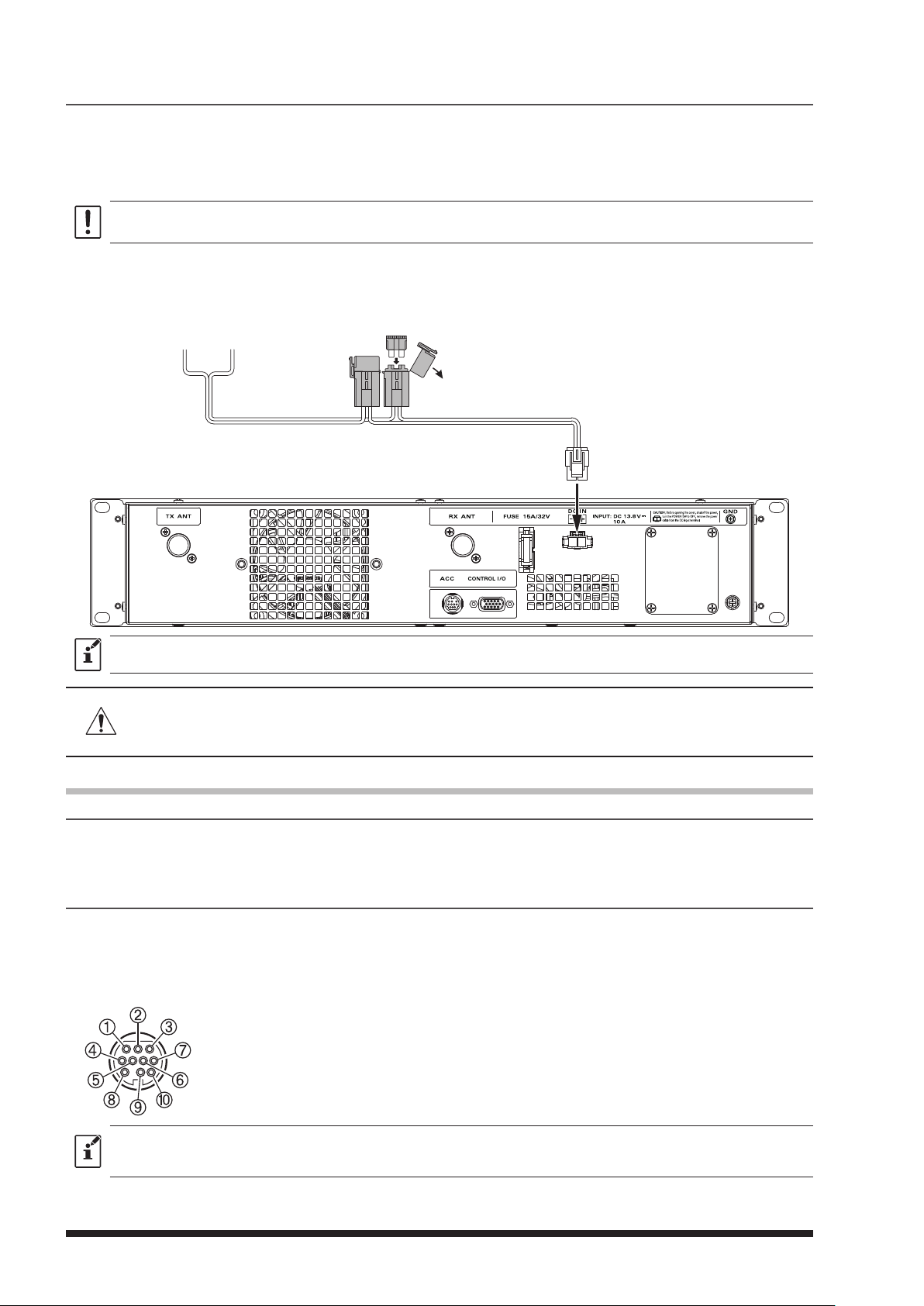
Fuse (15 A)
Follow the outline in the illustration regarding the proper connection for the required External Power Supply.
The DC power connector for the DR-1XE must only be connected to a DC source providing 13.8V DC (±15 %),
and capable of at least 10A of current.
Always observe proper polarity when making DC connection.
Make sure to switch OFF the power of the external power source before connecting.
1 Insert the connector of the provided DC power cord into the DC IN jack at the rear of the repeater.
2 Connect the red wire (+) of the provided DC power cord to the positive (+) terminal of the external power
source, and the black wire (-) to the negative (-) terminal.
–
(black)
The external power source should be installed near the equipment and should be easily accessible.
Permanent damage can result when improper supply voltage, or reverse-polarity voltage, is applied to the DR-1XE.
The Limited Warranty on this radio does not cover damage caused by application of AC voltage, reverse polarity
DC, or DC voltage outside the specified range of 13.8 V ±15 %. When replacing fuses, be certain to use a fuse of
the proper rating. The DR-1XE requires a 15A blade fuse.
+
(red)
Connecting External Devices
Connection of an external microphone
By connecting an optional microphone MH-48A6JA or MH-42C6J to the [MIC] jack on the front panel, voice
communications are possible in the mode which is set on the transmitter. Except when AMS is set on the
transmitter, data transmission is not available via the [MIC] jack.
Connection to a personal computer
The supplied PC connection cable “SCU-20” can be used to connect the repeater to a personal computer as
a USB port.
Use the [ACC] jack to connect with the optional WIRES-X Internet Linking Kit “HRI-200”.
The pin assignments of the [ACC] jack are as follows.
PKD (packet data input)
GND
PKS (PTT)
RX 9600 (9600 bps packet data output)
RX 1200 (1200 bps packet data output)
PK SQL (squelch control)
TXD (serial data output
RXD (serial data output
[
repeater PC])
[
repeater PC])
CTS (data communication control)
RTS (data communication control)
z Make sure to switch off the power to the radio before connecting the cable.
z When using the SCU-20, PC connection cable, a dedicated driver must be installed in the personal computer.
Download and use the driver and installation manual from the YAESU website.
6
Page 9
Accessories and Options
Supplied Accessories
AC Power Cord (T9017882)ø1 ...................................................................................................................... 1
DC Power Cord with Fuse (T9026115) ........................................................................................................... 1
Spare Fuse 15 A (Q0000075) .................................................................................................................. 1
5 A (Q0000143)ø1 .............................................................................................................. 1
Case Legs (S4000052) ................................................................................................................................... 4
PC Connection Cable SCU-20 ........................................................................................................................ 1
Operating Manual (this manual) ..................................................................................................................... 1
1: For DR-1X only (except the Australian version))
ø
Optional Accessories
DTMF Microphone MH-48A6JA
Hand Microphone MH-42C6J
Voice Guide Unit FVS-2
Name and Function of Each Component
Front Panel
X
POWER Switch
Press “|” side to switch the repeater ON, and “” side to switch the repeater OFF.
LED Indicator
• When the indicator illuminates in green, the power is supplied from the AC IN jack (DR-1X only).
• When the indicator illuminates in red, the power is supplied from the DC IN terminals (DR-1XE) or BACKUP
terminals (DR-1X).
SETUP Button
Press and hold to switch the display ON and OFF.
When a display is OFF, operation of a touch panel will be locked.
MIC Jack
Insert the plug of the optional microphone MH-48A6JA or MH-42C6J to this 6-pin modular jack.
Touch Panel Display
VOL Knob
The VOL knob adjusts the audio volume level of the received (uplink) signal and the beep sound.
Speaker
The internal speaker is located here.
Handle
7
Page 10

Rear Panel
DR-1X (US and Asian versions)
DR-1XE (European and Australian versions)
TX Antenna Terminal (N-type connector, 50 ohms)
Connect to the transmitting antenna (downlink) with the coaxial cable.
Cooling fan
RX Antenna Terminal (N-type connector, 50 ohms)
Connect to the receiving antenna (uplink) with the coaxial cable.
FUSE Holder (15A/ 32V)
A 15A fuse for the DC power supply through the BACKUP / DC IN jack is attached.
Power Supply BACKUP Jack (DR-1X) / DC IN jack (DR-1XE)
Connect to a 13.8V DC power supply with the supplied DC power cord.
FUSE Holder (DR-1X only)
A 5A fuse for the AC power supply through the AC IN jack is attached.
ACC Jack
Connect to a HRI-200 WIRES-X Interface Unit or a personal computer with the provided PC connection
cable “SCU-20”.
CONTROL I/O Connector
This connector allows the repeater to be connected to an external controller for remote operation.
AC IN Jack (DR-1X only)
Connect to a 100-240V AC line outlet with the supplied AC power cord.
GND Terminal
8
Page 11
1. Initial set up
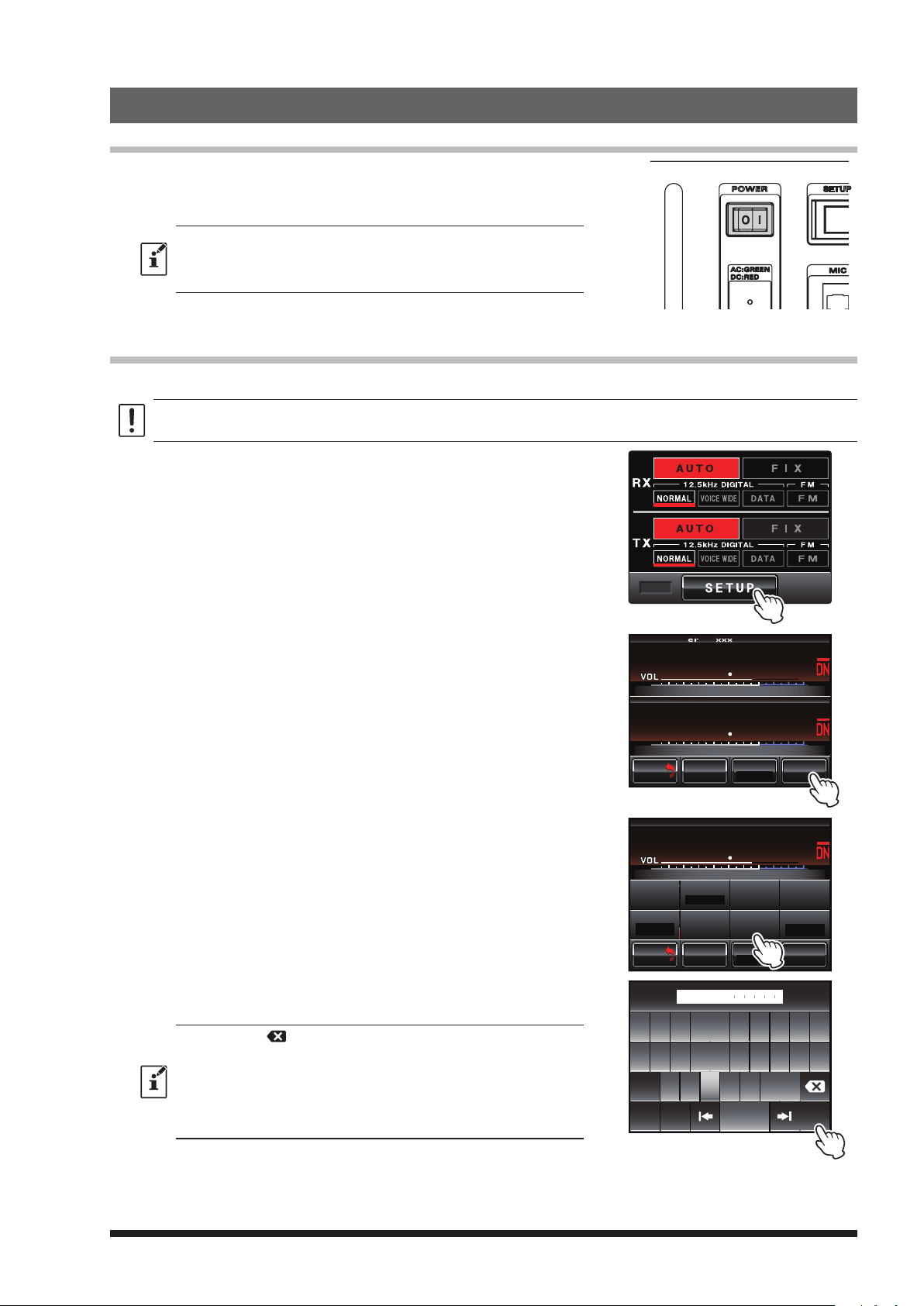
Turn the power on
1 Press the POWER switch.
The power will be switched ON, and the power supply monitor
(LED indicator) will illuminate.
z When the power is supplied from the AC IN jack, the indicator
illuminates in green (DR-1X only).
z When the power is supplied through the BACKUP terminals / DC
IN terminal (13.8V DC), the indicator illuminates in red.
The operation mode screen will appear on the display.
Set up the ID (call sign)
The call sign or ID must be entered for the first time after purchasing, or after resetting the repeater.
After performing a factory reset, the ID call sign setup begins with 2.
1 Touch
2 Touch
[
SETUP]
[F]
to display Frequency screen.
to display the Function screen pops up.
3 Touch ID SET area.
The character input screen will appear.
REMOTE
SETUP Ver.1.xxx EXP A1
L
P
N
U
PANEL1.XX DSP4.XX
DO
BACK
BACK
SETUP
U
DO
R-OFF
T-OFF
BACK
BACK
WN
M/V SQL
L
P
WN
SQL
M/V SQL
KI
8
L
N
KI
3
N
KI
8
ID MO D E
L
N
KI
DG-ID
MODE/REMOTE
7
7
Tx P W R
7
TIMER
ID SET
Tx P W R
HI
HI
F
ID AN NO U NCE
DEVIATION
WIDE
F
4 Touch a character key.
The touched character will be displayed at the top of the screen.
z Each time [
erase one character.
z The input screen changes between numbers input and alphabet
input each time [ABC] is touched.
z The cursor in the input field moves left or right when
are touched.
z Up to 10 alphabet characters, numbers, or the hyphen can be entered.
]
is touched the cursor will move to the left and
[|]
or [|]
5 Touch [ENT].
The ID setting is saved and the display will return to the Function
screen.
W D X C6
ID SET
Q W E R T Y U I O P
-
A S D F G H J K L
Z X C V B N M
Caps
ABC Space
#%^
ENT
9
Page 12
2. Set up Operation Mode
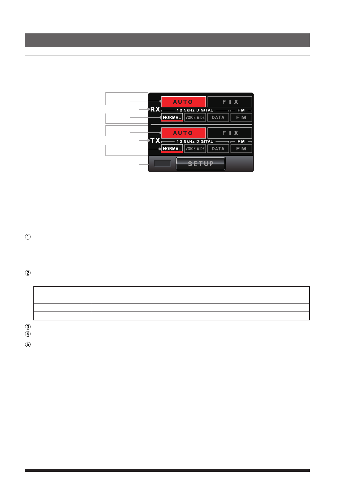
TX (downlink)
RX (uplink)
When the Power Switch is turned ON, Operation Mode screen appears.
This screen is for normal operation.
The DR-1X could be set up with two frequencies for the uplink and the downlink and also different operation
modes for each frequency.
To receive Analog FM and Digital C4FM signals simultaneously, set RX to [AUTO] mode.
This mode may activate the AMS (Automatic Mode Select) function, then receive (uplink) and transmit
(downlink) signals of the Analog FM and Digital C4FM. The default setting is [AUTO].
If operating the repeater using the DG-ID, select the [NORMAL] in the [FIX] mode.
available because the Analog FM mode does not include the DG-ID information.
In the C4FM digital mode, three digital modes are recognized automatically. In normal C4FM digital, it will be
in V/D mode.
Touch [AUTO] or [FIX] in the operation mode screen area to set the operating mode.
[
AUTO] Touch here to activate the AMS function. The mode switches automatically according to the
received/transmitted signal types. [AUTO] is turned red, [NORMAL] automatically light up.
[
FIX] Touch here to activate the FIX mode. [FIX] is turned yellow.
mode, that other mode signals may not be received.
Either [VOICE WIDE] or [DATA] modes are automatically recognized in the C4FM uplink Signal, and receive
mode is changed to fit the signals, so no setting is necessary.
[
NORMAL
[
VOICE WIDE
[
DATA
[FM]
RX indicator This indicator shows green when a signal is received and white when there is no signal.
TX indicator This indicator shows red when the repeater transmits and white when there is no transmit.
]
]
]
Normal C4FM digital mode
High-rate voice C4FM digital mode
High-speed data C4FM digital mode
Analog FM communication mode
REMOTE
The DG-ID function is not
Note that when selecting the [FIX]
[REMOTE] Displayed in red when remote operation with an external controller is enabled (see page 33).
[
SETUP
10
]
Touch here to switch the display to set up the frequency.
Page 13
3. Set up Frequency
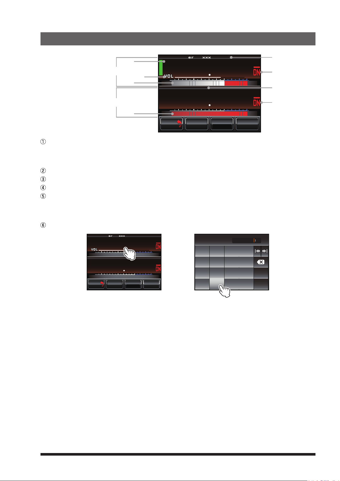
TX (downlink)
SETUP Ver.1.xxx EXP A1
L
P
U
RX (uplink)
PANEL1.XX DSP4.XX
DO
BACK
BACK
Status display area
A green bar is displayed during receive when signals are detected.
The bar will not be displayed when the squelch is turned on and the received signal level is below the
squelch level.
VOL/SQL level display
S-meter level display
PO-meter level display
Firmware Version Information
Ver. x.xx: RX-UNIT CPU Firmware Version
PANEL x.xx: PANEL-UNIT CPU Firmware Version
DSP x.xx: DSP-UNIT CPU Firmware Version
Mode display
SETUP Ver.1.xxx EXP A1
L
P
N
U
PANEL1.XX DSP4.XX
DO
BACK
BACK
KI
L
WN
M/V SQL
8
7
N
KI
7
3
Tx P W R
HI
F
N
KI
L
WN
M/V SQL
à
8
7
N
KI
7
3
Tx PWR
UP LINK
*
#
HI
F
8
. 7
A
B
Space
C
ENT
D
Touch [SETUP] to display the frequency set up screen, then set the uplink and downlink frequency.
Touch the uplink frequency, the numeric input popup screen appears. Input the uplink frequency.
After completing the input frequency, the input popup screen automatically disappears and the input frequency
is set.
Input the downlink frequency in the same way.
Touch [Back] to return to the operation mode screen.
11
Page 14
4. Set up Other Functions
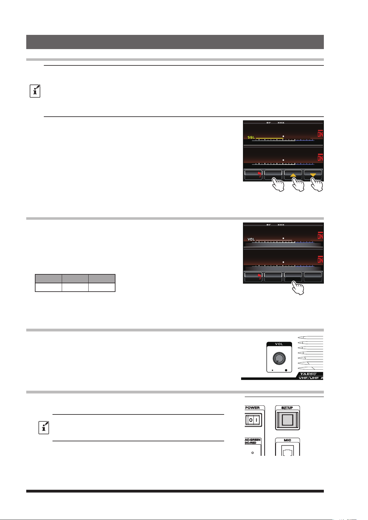
Adjusting the squelch level
z When the squelch level is set to “open” the repeater will transmit, so the TX output must be connected to the duplexer
and antenna.
z Use extreme caution when making the squelch adjustment or measurement with a signal generator. Do not connect
the signal generator to the duplexer antenna port. To avoid damage to the test equipment, always connect the signal
generator directly to the RX antenna connector on the DR-1X.
z While the squelch level is being set, repeater transmit operation is temporarily permitted. This will facilitate checking
the performance of the Duplexer, and allow evaluation of the receiver sensitivity degradation (“desense”), during
simultaneous transmit/receive operation.
1 Touch [SETUP].
The setup mode screen will appear.
2 Touch [SQL].
When [SQL] turns yellow, the VOL meter below the RX band frequency
display, will change to the SQL meter and show the squelch level
setting.
3 Touch [▲] or [▼] to adjust the squelch level.
The level will be displayed in the SQL meter.
4 Touch [BACK].
The squelch level is set, and the display will return to the operation
mode screen.
SETUP Ver.1.xxx EXP A1
L
P
N
U
PANEL1.XX DSP4.XX
DO
BACK
BACK
KI
L
WN
M/V SQL
8
7
N
KI
7
3
Adjusting the transmit power
1 Touch [SETUP].
The setup mode screen will appear.
2 Touch [Tx PWR] to select the transmit power.
The setting is changed in the following sequence, each time
[
Tx PWR] is touched.
“HI” à “LO” à “MD” à
HI MD LO
50 W 20 W 5 W
3 Touch [BACK].
The transmit power level is set, and the display will return to the
operation mode screen.
Adjusting the volume
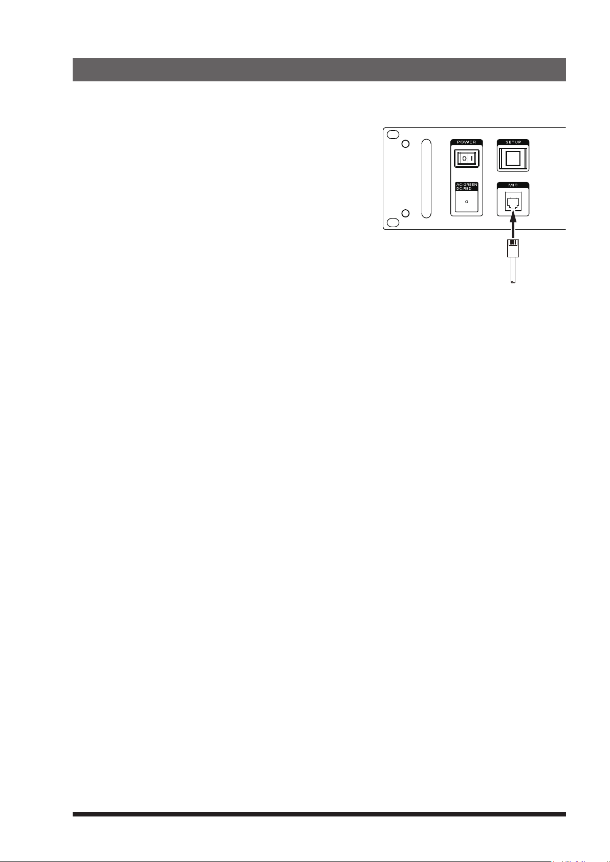
Turn the VOL knob.
The VOL knob adjusts the audio volume level of the received (uplink) signal.
Turning the display ON and OFF
1 Press and hold the SETUP button to turn the display OFF.
When a display is OFF, operation of the touch panel will be locked.
The display will turn OFF automatically after a period of time (default 1
min) with no operation.
The display duration time setting may be selected from “1min”, “5min”,
“10min”, or “30min” (see page 27 “Setting the display turn-off time”).
SETUP Ver.1.xxx EXP A1
L
P
N
U
PANEL1.XX DSP4.XX
DO
BACK
BACK
KI
L
WN
M/V SQL
8
7
N
KI
7
3
Tx P W R
HI
F
2 Press and hold the SETUP button for 3 seconds to turn the display
ON.
12
Page 15
5. Base mode operation
MH-48A6JA or MH-42C6J
The repeater can be used as a VHF/UHF base station by connecting an optional MH-48A6JA or MH-42C6J
microphone to the “MIC” jack on the front panel.
13
Page 16
6. Set up DG-ID Number
Digital Group Identication (DG-ID)
The Digital Group Identification (DG-ID) feature controls access to the repeaters by using the two-digit numbers
from 01 to 99.
This feature is similar to the CTCSS function used in the Analog FM mode.
The DG-ID number 00 detects signals with all ID numbers.
The default DG-ID number is set to “00”. All the C4FM digital stations' uplink signal may be operated.
• If operating this repeater using the DG-ID, select the FIX DIGITAL mode in the operation mode screen. The
DG-ID function is not available because the Analog FM mode does not include the DG-ID information.
In order to use the DG-ID feature, update the C4FM digital transceivers to the latest firmware compatible with
the DG-ID feature.
• The latest firmware for each transceiver is available on the YAESU website.
• The DR-1X will repeat on the downlink, only the uplink signals with the corresponding DG-ID number if the
DG-ID number is set to an arbitrary number from “01” to “99”, other than “00”. Signals with a different DG-ID
number will not transmit on the downlink.
• If the DG-ID number is set to “00”, all the C4FM digital signals are transmitted on the downlink.
• DG-ID numbers may be registered in the DG-ID memories (up to 100 entries).
Setting the DG-ID Number
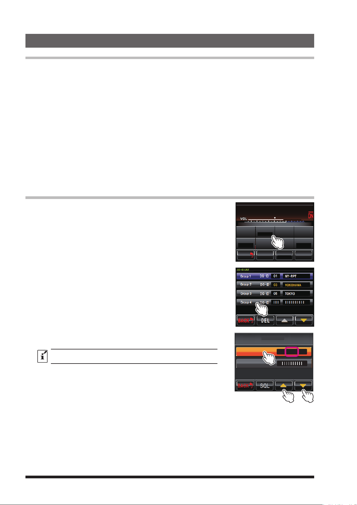
1 Touch [SETUP] to display the frequency set up screen, then touch [F]
on the bottom of the screen.
2 Keep touching [ID MODE] (DG-ID).
The DG-ID list screen appears.
SETUP
P
U
WN
DO
SQL
R-OFF
T-OFF
BACK
M/V SQL
BACK
L
N
L
MODE/REMOTE
KI
ID MO D E
N
DG-ID
KI
TIMER
ID SET
Tx P W R
HI
ID AN NO U NCE
DEVIATION
WIDE
F
3 Touch the Group you want to register twice.
The group setting screen appears.
4 Touch [▲] or [▼] to select the desired DG-ID number to be registered
to the DR-1X repeater.
When using the DR-1X as an Open Repeater that anyone may use, set
the DG-ID to “00”.
When group name change is unnecessary à proceed to step 8.
DG-ID
Group Name
Group 4
> DG-ID 50
14
Page 17
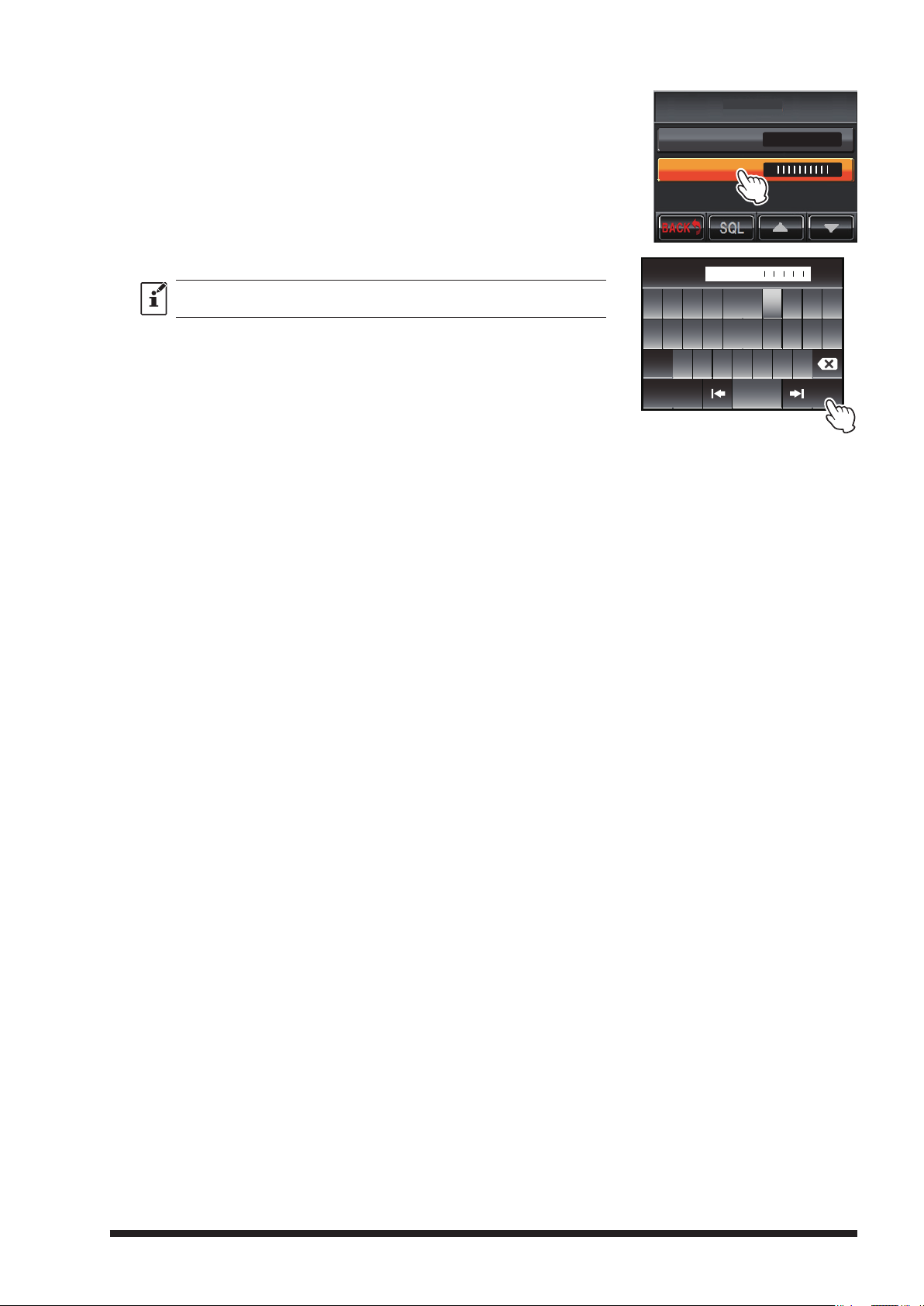
5 Touch [Group Name] twice.
The character input screen appears.
DG-ID
DG-ID
Group Name
Group 4
>
50
6 Input the name to be registered to the DR-1X repeater.
Up to 10 characters may be input.
7 Touch [ENT].
The input characters are registered and operation returns to the group
setting screen.
8 Touch [BACK] 4 times.
The screen returns to the operation mode screen.
NAME SET
Q W E R T Y U I O P
-
A S D F G H J K L
Z X C V B N M
Caps
ABC Space
#%^
UESAY
ENT
15
Page 18
7. Set up DP-ID
Digital Personal Identication (DP-ID)
Digital Personal Identification (DP-ID) is the digital ID number each transceiver is programmed with. The
system manager may operate the DR-1X repeater functions, by registering the DG-ID number of the controlling
C4FM digital transceiver to the DR-1X.
In order to use the DP-ID feature, update the C4FM digital transceivers to the latest firmware compatible with
the DP-ID feature.
• The latest firmware for each transceiver is available on the YAESU website.
• The DP-ID may be registered in the DP-ID memories (up to 24 items).
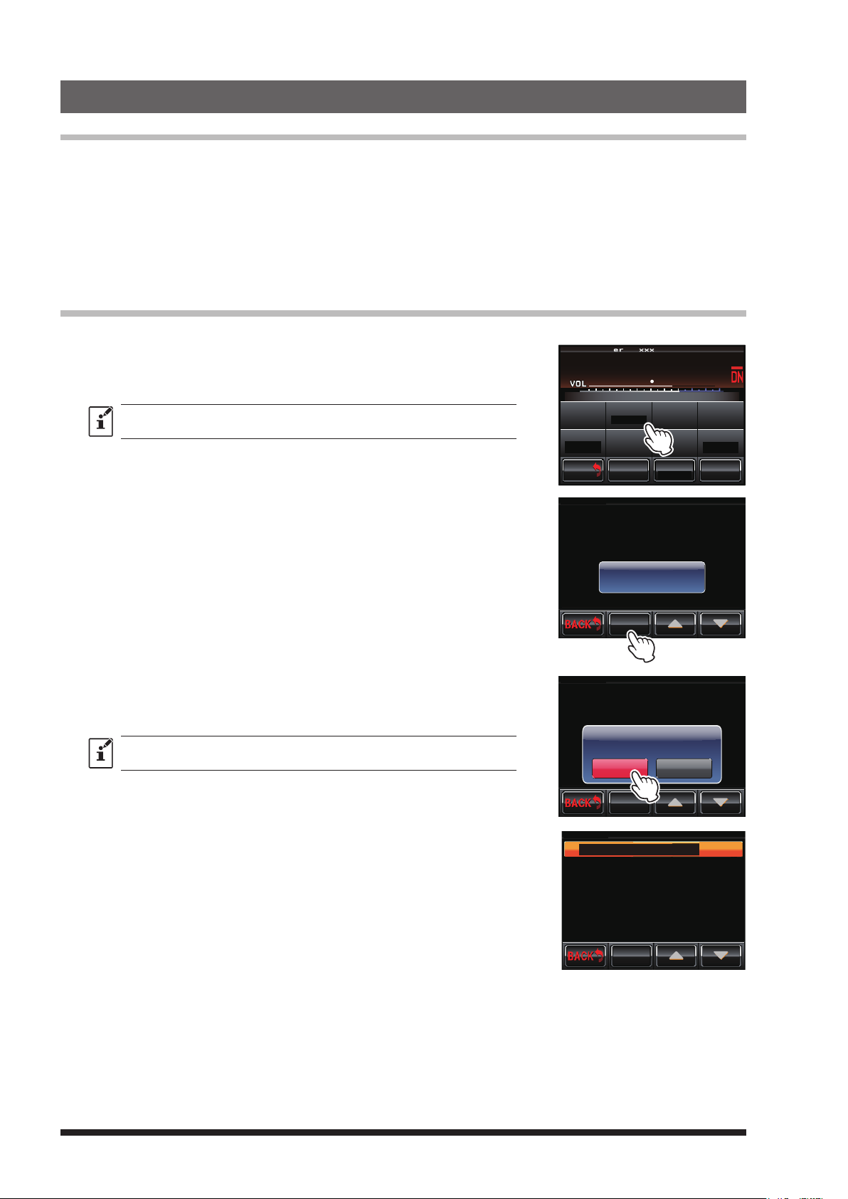
Registering the DP-ID
1 Touch [SETUP] to display the frequency set up screen, then touch [F] on the bottom of the screen.
2 Touch [ID MODE] to select the “DP-ID”.
Touching [ID MODE] switches the setting as follows:
à “DP-ID” à “DG-ID” à “DP-ID” à
The DP-ID display returns to the DG-ID display in about 5 seconds.
3 Keep touching [ID MODE] (DP-ID) for more than two seconds.
The DP-ID list screen appears.
4 Touch [REG].
The Registration Confirmation Screen appears for about 5 seconds.
5 Tune the registering transceiver to the repeater frequency, then trans-
mit in the C4FM mode.
• The call sign and Radio ID from the received transceiver are dis-
played.
SETUP Ver.1.xxx EXP A1
L
P
N
U
DO
R-OFF
T-OFF
BACK
BACK
DP-ID LIST
CONTROL MODE
ACTIVATE
DEACTIVATE
FIX DIGITAL
AUTO
KI
ID MO D E
L
N
WN
DP-ID
SQL
MODE/REMOTE
M/V SQL
DP-ID Registrasion?
REG
KI
TIMER
ID SET
Tx P W R
HI
ID AN NO U NCE
DEVIATION
WIDE
F
DTMF
*1111
*2222
*3333
*4444
6 Touch [OK?] to register Radio ID, or touch [Cancel] to return to the
DP-ID list screen without registering.
• If registering another transceiver, repeat step 4 to 6.
Up to 24 DP-ID information data may be registered.
7 Touch [BACK] 3 times.
The screen returns to the operation mode screen.
DP-ID LIST
CONTROL MODE
ACTIVATE
DEACTIVATE
DP-ID Registration
FIX DIGITAL
O K ? Cance
AUTO
REG
DP-ID LIST
1
F T 2 D R x x x x x
ACTIVATE
DEACTIVATE
FIX DIGITAL
AUTO
REG
DTMF
*1111
Radio ID:xxxxxFT2DR
*2222
*3333
*4444
DTMF
*1111
*2222
*3333
*4444
16
Page 19
Delete the registered DP-ID
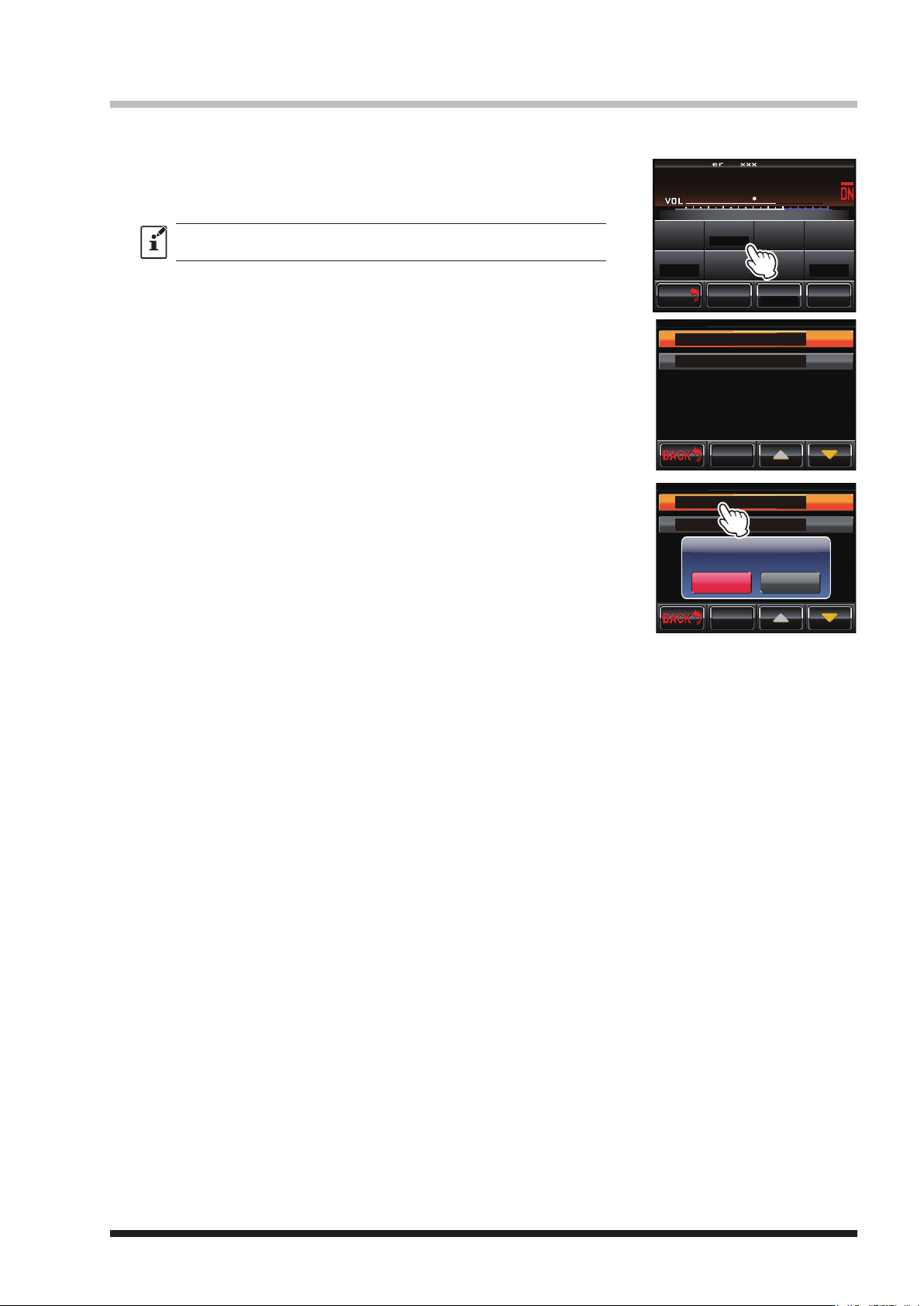
1 Touch [SETUP] or [B SETUP] to display the frequency set up screen, then touch [F] on the bottom of the
screen.
2 Touch [ID MODE] to select the “DP-ID”.
Touching [ID MODE] switches the setting as follows:
à “DP-ID” à “DG-ID” à “DP-ID” à
The DP-ID display returns to the DG-ID display in about 5 seconds.
3 Keep touching [ID MODE] (DP-ID) for more than two seconds.
The DP-ID list screen appears.
SETUP Ver.1.xxx EXP A1
L
P
N
U
DO
R-OFF
T-OFF
BACK
BACK
DP-ID LIST
1
2
DEACTIVATE
FIX DIGITAL
AUTO
KI
ID MO D E
L
N
WN
SQL
M/V SQL
FT2DR xxxxx
FT1XDR xxxxx
DP-ID
MODE/REMOTE
REG
KI
TIMER
ID SET
Tx P W R
HI
ID AN NO U NCE
DEVIATION
WIDE
F
DTMF
*2222
*3333
*4444
Touch the desired DP-ID to delete.
4
DELETE (Deletion Confirmation Screen) appears.
5 Touch the [OK?] to delete or touch the [Cancel] to return to the DP-ID
list screen without deleting.
• If deleting another transceiver, repeat step 4 to 5.
Touch [BACK].
6
The screen returns to the setup screen.
DP-ID LIST
1
FT2DR xxxxx
FT1XDR xxxxx
2
DEACTIVATE
FIX DIGITAL
AUTO
DELETE
O K ? C ance
REG
DTMF
*2222
*3333
*4444
• If using the DP-ID, select the FIX Digital mode in the operation mode screen. When transmitting the DP-ID
signal, set the transceiver to C4FM mode.
The system manager may control the repeater setting remotely from designated transceivers by using this
function.
The transceivers compatible with the remote-control is the FTM-400D, FTM-100D, FTM-3200D and FTM-
3207D.
Example:
• Sets the repeater function ON or OFF
• Changing Downlink Transmission Power
• Setting of the Emergency Call
17
Page 20
8. Remote Controls
COMMAND LIST
Setting the remote control
• Remote control of the DR-1X repeater can be performed in either C4FM digital mode or analog FM mode.
For C4FM digital mode, use the FTM-400D, FTM-100D, FTM-3200D or FTM-3207D transceiver. For
security reasons, we recommend using a mobile C4FM transceiver with the DP-ID that is registered to the
DR-1X repeater.
• Remote operation sends commands on the uplink frequency.
• When remote control is required, it is necessary to set whether to control the DR-1X with analog FM or
C4FM in advance.
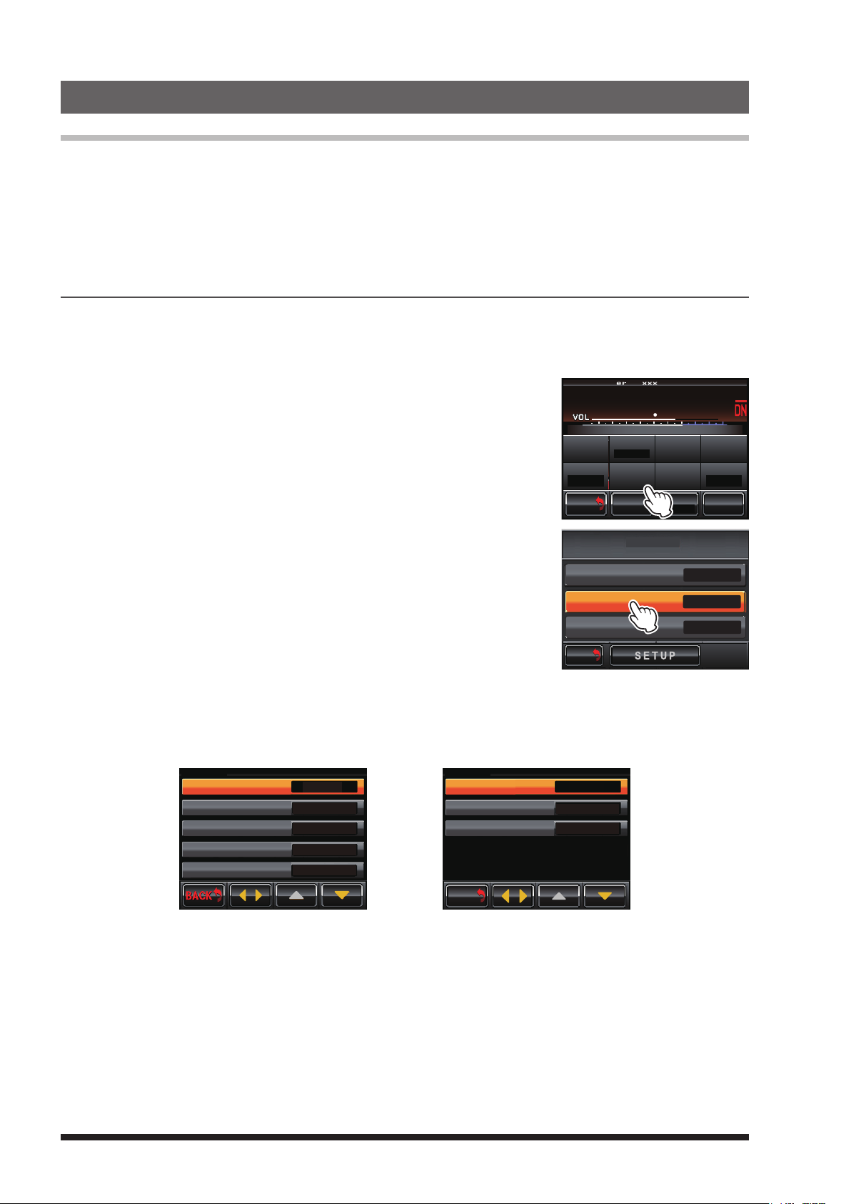
Selection of analog FM, C4FM digital
Touch [SETUP] on the operation mode screen.
1
The setup mode screen will appear.
2 Touch
The setup menu will appear.
3 Touch
The menu list will appear.
[F]
in the setup mode screen.
[
MODE/REMOTE].
SETUP Ver.1.xxx EXP A1
L
P
N
U
DO
R-OFF
T-OFF
BACK
BACK
WN
SQL
M/V SQL
KI
ID MO D E
L
N
KI
DG-ID
MODE/REMOTE
TIMER
ID SET
Tx P W R
HI
ID AN NO U NCE
DEVIATION
WIDE
F
4 Select and touch
[
COMMAND] twice.
REMOTE / COMMAND / DISP TIMER
The command list will appear.
REMOTE
DG-ID
COMMAND
DISPLAY TIMER
BACK
M/V
BACK
5 Touch
[
tu].
The set value will change in the following sequence each time [tu] is touched.
à “DIGITAL” (C4FM Digital) à “ECS” (Analog FM) à “DIGITAL” (C4FM Digital) à
COMMAND LIST
CONTROL MODE
ACTIVATE
DEACTIVATE
FIX DIGITAL
AUTO
DIGITAL
*1111
*2222
*3333
*4444
DIGITAL (C4FM Digital)
CONTROL MODE
ACTIVATE
DEACTIVATE
FIX DIGITAL
AUTO
BACK
M/V
BACK
ECS (Analog FM)
Tx P W R
LO
ECS
2 7 * 30
2 6 * 30
*3333
*4444
OFF
>
>
>
ON
F
6 Touch
[
BACK] 4 times.
The screen returns to the operation mode screen.
18
Page 21
C4FM DIGITAL CONTROL
• Set the operation mode to “AUTO” or “FIX NORMAL”.
• The transceivers compatible with the remote-control are the FTM-400D, FTM-100D, FTM-3200D and FTM-
3207D.
• Remote control with C4FM digital can be done only when the transceiver DP-ID has been registered to the
DR-1X in advance. Remote operation cannot be performed with a transceiver when the DP-ID has not been
registered, so you can securely manage repeaters.
• When the remote operation is accepted, the repeater responds and the operation completion is shown by
the respective functions on the screen of the mobile transceiver.
ECS (for analog FM mode)
• Set the operation mode to “AUTO” or “FIX FM”.
• Any transceiver with ECS (Enhanced Code Squelch) code can be used.
• When the remote operation is accepted, the CW ID of the operation that has been completed by the respec-
tive function is transmitted on the repeater downlink frequency.
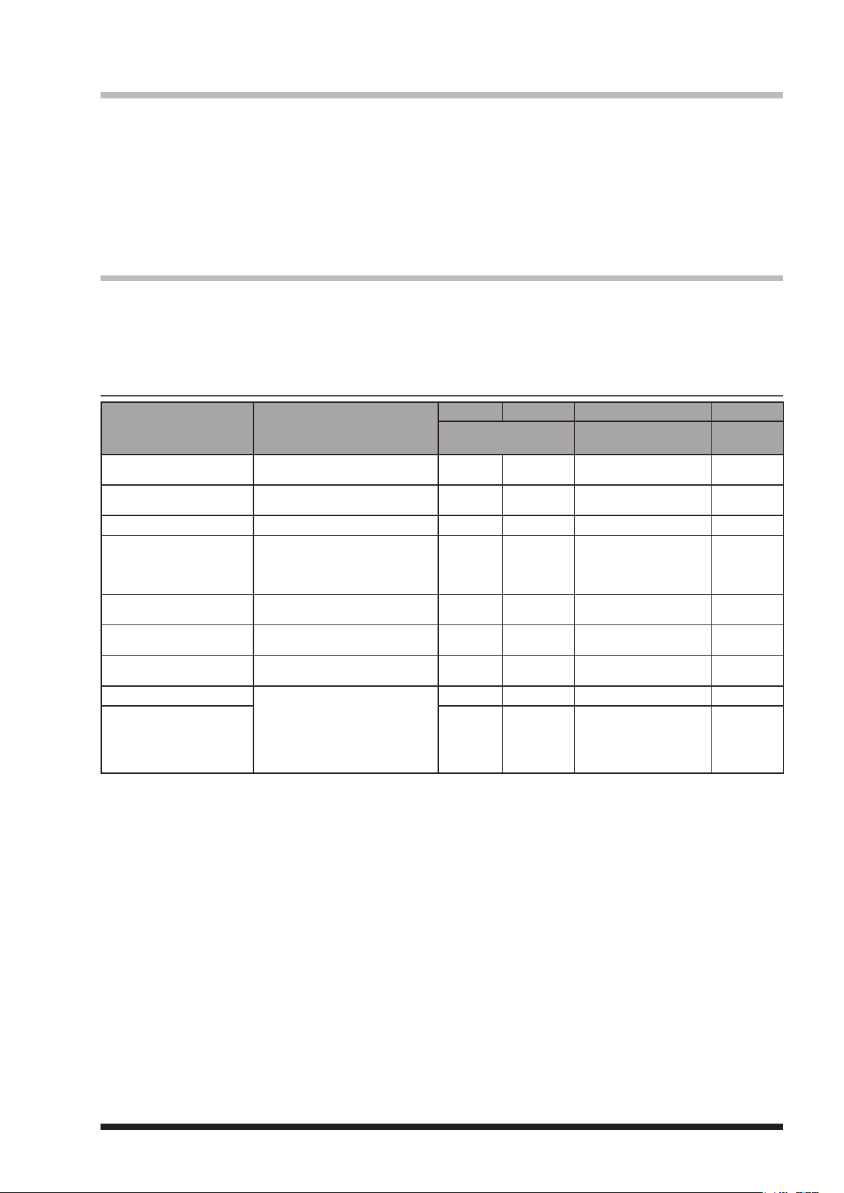
Remote Control Command List (Default setting)
Function Description
ACTIVATE
DEACTIVATE
FIX DIGITAL
AUTO
HIGH TX POWER
MID TX POWER
LOW TX POWER
EMERGENCY CALL OFF
EMERGENCY CALL ON
Activate the repeater operation
of CH-A and CH-B.
Deactivate the local repeater
operation.
Set the repeater to C4FM mode.
Set the repeater to AMS (Automatic Mode Select) mode.
Both analog FM and C4FM digi-
tal signals operate.
Set the transmit power to HI (50
W).
Set the transmit power to MD
(20 W).
Set the transmit power to LO (5
W).
When accessing the repeater
by a transceiver with registered
DP-ID, select the downlink from
the repeater or the downlink in
accordance with the DG-ID set-
ting.
C4FM
Analog FM
Code
1111 ECS
2222 ECS
ø1
3333
ø1
4444
ø1
0050
ø1
0020
ø1
0005
ø1
8888
ø1
9999
ø2
ø2
- DIGI/DIGI Set -
- AUTO/AUTO Set -
- High Power Set -
- Mid Power Set -
- Low Power Set -
- EMERGENCY OFF -
- EMERGENCY ON -
C4FM
Display of the
transceiver screen
Activate Set O
Local Deactivate Set S
Analog FM
CW ID
ø1: It is only available with the C4FM digital.
ø2: For additional details on this function, refer to page 21.
When remote control is activated by a Digital Code, the status is shown on the transceiver display.
When remote control is activated by ECS, the status is responded with CW ID on the Downlink frequency.
19
Page 22
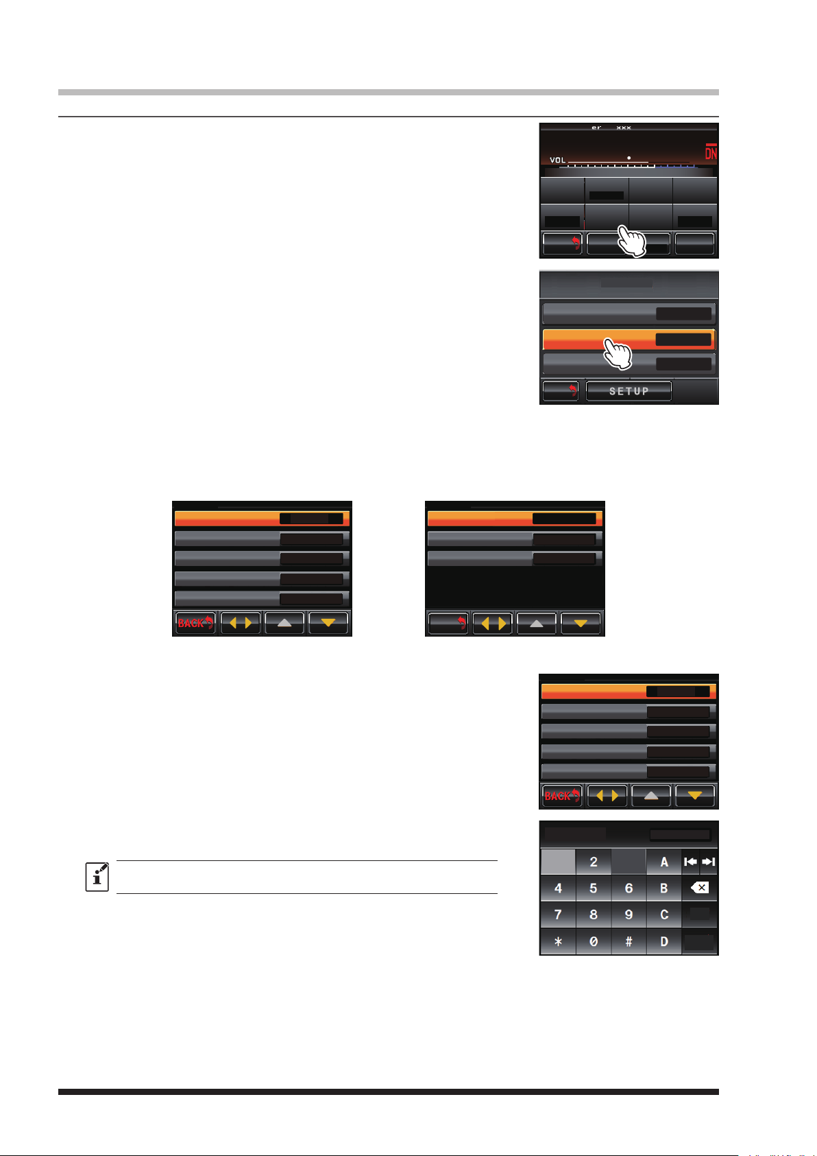
Change the remote command
To change the factory command code of C4FM digital
1
Touch [SETUP] on the operation mode screen.
The setup mode screen will appear.
2 Touch [F] on the setup mode screen.
The setup menu will appear.
3 Touch [MODE/REMOTE].
The menu list will appear.
SETUP Ver.1.xxx EXP A1
L
P
N
U
DO
R-OFF
T-OFF
BACK
BACK
WN
SQL
M/V SQL
KI
ID MO D E
L
N
KI
DG-ID
MODE/REMOTE
TIMER
ID SET
Tx P W R
HI
ID AN NO U NCE
DEVIATION
WIDE
F
4 Touch [COMMAND] twice.
REMOTE / COMMAND / DISP TIMER
The command list will appear.
REMOTE
DG-ID
COMMAND
DISPLAY TIMER
BACK
M/V
BACK
[
5 Touch
] to select “DIGITAL”
tu
.
The set value will change in the following sequence each time [tu] is touched.
à “DIGITAL” (C4FM Digital) à “ECS” (Analog FM) à “DIGITAL” (C4FM Digital) à
COMMAND LIST
CONTROL MODE
ACTIVATE
DEACTIVATE
FIX DIGITAL
AUTO
DIGITAL
*1111
*2222
*3333
*4444
DIGITAL (C4FM Digital)
6 Touch [▲] or [▼] to select the desired command.
7 Touch the command to enable setting the remote control code.
COMMAND LIST
CONTROL MODE
ACTIVATE
DEACTIVATE
FIX DIGITAL
AUTO
BACK
M/V
BACK
ECS (Analog FM)
Tx P W R
LO
COMMAND LIST
CONTROL MODE
ACTIVATE
DEACTIVATE
FIX DIGITAL
AUTO
ECS
2 7 * 30
2 6 * 30
*3333
*4444
OFF
>
>
>
ON
F
DIGITAL
*1111
*2222
*3333
*4444
8 Enter a 4-digit control code.
The screen returns to the command list.
z The same code as another function may not be set.
z Touch [D] to delete the 4-digit code and disable that command.
9 Touch
[
BACK] 4 times.
The screen returns to the operation mode screen.
20
ACTIVATE
1 3
*1111
Space
ENT
Page 23
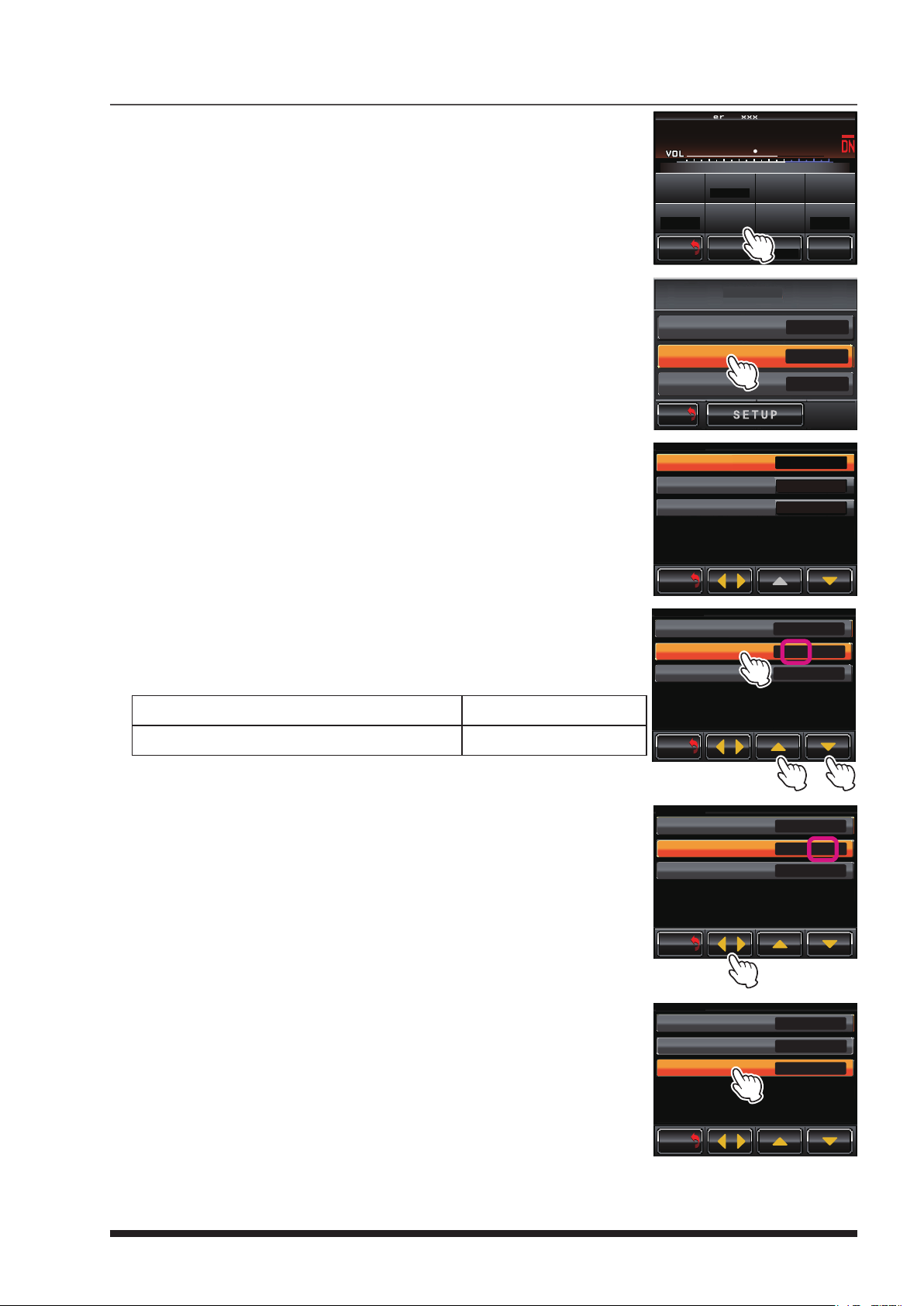
To change the factory command code of analog FM
COMMAND LIST
1
Touch [SETUP] on the operation mode screen.
The setup mode screen will appear.
2 Touch [F] on the setup mode screen.
The setup menu will appear.
3 Touch [MODE/REMOTE].
The menu list will appear.
SETUP Ver.1.xxx EXP A1
L
P
N
U
DO
R-OFF
T-OFF
BACK
BACK
WN
SQL
M/V SQL
KI
ID MO D E
L
N
KI
DG-ID
MODE/REMOTE
TIMER
ID SET
Tx P W R
HI
ID AN NO U NCE
DEVIATION
WIDE
F
4 Touch [COMMAND] twice.
The command list will appear.
[
5 Touch
] to select “ECS”
tu
.
The set value will change in the following sequence each time [tu]
is touched.
à “DIGITAL” (C4FM Digital) à “ECS” (Analog FM) à
The ECS (Enhanced Code Squelch) code setting screen will be
displayed.
6 Touch
[
ACTIVATE] twice.
7 Touch [▲] or [▼] repeatedly to select the first ACTIVATE code.
Refer to the following table when setting the ECS (Enhanced Code
Squelch) of the transceiver that is used to control the DR-1X.
When RX Tone is 151.4 Hz or less, or DCS is “ON” 01 (67 Hz) to 25 (151.4 Hz)
When RX Tone is 156.7 Hz or higher, or RX Tone is “OFF” 26 (156.7 Hz) to 50 (254.1 Hz)
REMOTE / COMMAND / DISP TIMER
OFF
Tx P W R
LO
Tx P W R
LO
>
>
>
ON
ECS
2 7 * 30
2 6 * 30
*3333
*4444
ECS
[27]* 30
[ 0 1 ] * 05
26 * 30
*3333
*4444
F
F
REMOTE
DG-ID
COMMAND
DISPLAY TIMER
BACK
M/V
BACK
COMMAND LIST
CONTROL MODE
ACTIVATE
DEACTIVATE
FIX DIGITAL
AUTO
BACK
M/V
BACK
COMMAND LIST
CONTROL MODE
ACTIVATE
DEACTIVATE
DEACTIVATE
FIX DIGITAL
AUTO
BACK
M/V
BACK
8 Touch [◄►]
The cursor “[ ]” moves.
9 Touch [▲] or [▼] repeatedly to select the second ACTIVATE code
The second code must be different from the first code.
10 Touch
Select the DEACTIVATE code in the same manner as described in steps 7 to
11 Touch
The screen returns to the operation mode screen.
[
DEACTIVATE] twice.
9.
[
BACK] 4 times.
CONTROL MODE
ACTIVATE
DEACTIVATE
DEACTIVATE
FIX DIGITAL
AUTO
BACK
M/V
BACK
COMMAND LIST
CONTROL MODE
ACTIVATE
DEACTIVATE
DEACTIVATE
FIX DIGITAL
AUTO
BACK
M/V
BACK
Tx P W R
LO
Tx P W R
LO
ECS
27 *[30]
[ 0 1 ] * 05
26 * 30
*3333
*4444
F
ECS
0 2 * 05
[ 0 1 ] * 05
[ 0 1 ] * 05
*3333
*4444
F
21
Page 24
9. Actual remote control procedure
Remote Control for C4FM Digital
When controlling remotely with the FTM-400D
1 Please confirm that the FTM-400D DP-ID is registered on the DR-1X repeater.
2
Tune the transmit frequency of the FTM-400D to the uplink frequency of the DR-1X.
3 Set the FTM-400D to the digital mode, then press and hold the “Û” key on the microphone (MH-48A6JA).
4 “REMOTE REC/PLY” is displayed on the top of the FTM-400D screen, the remote-control is available.
• To cancel the remote-control, press the “Û” key on the microphone (MH-48A6JA).
5 Input the 4-digits remote command by using the numeric keys (MH-48A6JA).
• Press the “Û” key on the microphone (MH-48A6JA) to cancel the input command at any point in the process.
6 Press the “#” key on the microphone (MH-48A6JA) to transmit the input command.
7 After transmitting the command, press the “Û” key on the microphone (MH-48A6JA) to return to the normal
operation.
z If the FTM-400D firmware is not compatible with the DP-ID function, update to the latest firmware to use the DP-ID
function.
z The latest firmware is available on the YAESU website.
When controlling remotely with the FTM-100D
1 Please confirm that the FTM-100D DP-ID is registered on DR-1X repeater.
2
Tune the transmit frequency of the FTM-100D to the uplink frequency of the DR-1X.
3 Set the FTM-100D to the digital mode, then press and hold the “Û” key on the microphone (MH-48A6JA).
4 “REC/PLY” is displayed on the top of the screen of the FTM-100D, the remote-control is available.
• Cancelling the remote-control, press the “Û” key on the microphone (MH-48A6JA).
5 Input the 4-digits remote command by using the numeric key (MH-48A6JA).
• Press the “Û” key on the microphone (MH-48A6JA) to cancel the input command at any point in the process.
6 Press the “#” key on the microphone (MH-48A6JA) to transmit the input command.
7 After transmitting the command, press the “Û” key on the microphone (MH-48A6JA) to return to the normal
operation.
z If the FTM-100D firmware is not compatible with the DP-ID function, update to the latest firmware to use the DP-ID
function.
z The latest firmware is available on the YAESU website.
When controlling remotely with the FTM-3200D
1 Please confirm that the FTM-3200D DP-ID is registered on DR-1X repeater.
2
Tune the transmit frequency of the FTM-3200D to the uplink frequency of the DR-1X.
3 Set the FTM-3200D to the digital mode, then press and hold the “Û” key on the microphone (MH-48A6JA).
4 “REMOTE” is displayed on the screen of the FTM-3200D, the remote-control is available.
• Cancelling the remote-control, press the “Û” key on the microphone (MH-48A6JA).
5 Input the 4-digits remote command by using the numeric key (MH-48A6JA).
• Press the “Û” key on the microphone (MH-48A6JA) to cancel the input command at any point in the process.
6 Press the “#” key on the microphone (MH-48A6JA) to transmit the input command.
7 After transmitting the command, press the “Û” key on the microphone (MH-48A6JA) to return to the normal
operation.
z If the FTM-3200D firmware is not compatible with the DP-ID function, update to the latest firmware to use the DP-ID
function.
z The latest firmware is available on the YAESU website.
22
Page 25
When controlling remotely with the FTM-3207D
1 Please confirm that the FTM-3207D DP-ID is registered on DR-1X repeater.
2
Tune the transmit frequency of the FTM-3207D to the uplink frequency of the DR-1X.
3 Set the FTM-3207D to the digital mode, then press and hold the “Û” key on the microphone (MH-48A6JA).
4 “REMOTE” is displayed on the screen of the FTM-3207D, the remote-control is available.
• Cancelling the remote-control, press the “Û” key on the microphone (MH-48A6JA).
5 Input the 4-digits remote command by using the numeric key (MH-48A6JA).
• Press the “Û” key on the microphone (MH-48A6JA) to cancel the input command at any point in the process.
6 Press the “#” key on the microphone (MH-48A6JA) to transmit the input command.
7 After transmitting the command, press the “Û” key on the microphone (MH-48A6JA) to return to the normal
operation.
z If the FTM-3207D firmware is not compatible with the DP-ID function, update to the latest firmware to use the DP-ID
function.
z The latest firmware is available on the YAESU website.
Remote Control for Analog FM
In analog FM mode, the ON/OFF setting of the repeater can be operated remotely.
Remote Control can only be operated from a transceiver* capable of sending a code combining two CTCSS
tones.
*: FT2D/DE, FT1XD/DE, FTM-400XDR/XDE, FTM-100DR/DE, FTM-3200DR/DE, and FTM-3207DR/DE.
1 Set the same code that is registered in the DR-1X into the transceiver that can transmit the two combined
CTCSS tones.
Function Code
Activate the repeater operation The same code as “ACTIVATE” of DR-1X
Deactivate the repeater operation The same code as “DEACTIVATE” of DR-1X
For instructions on setting the codes, refer to the Transceiver Operating Manual.
2 Set the transceiver to the analog FM mode.
3 When the remote operation code is accepted, the CW ID of the operation that has been completed is
transmitted on the repeater downlink frequency.
Description CW ID
When the repeater operation is resumed CW “O” (– – –) is transmitted
When the repeater operation is stopped CW “S” (• • •) is transmitted
23
Page 26
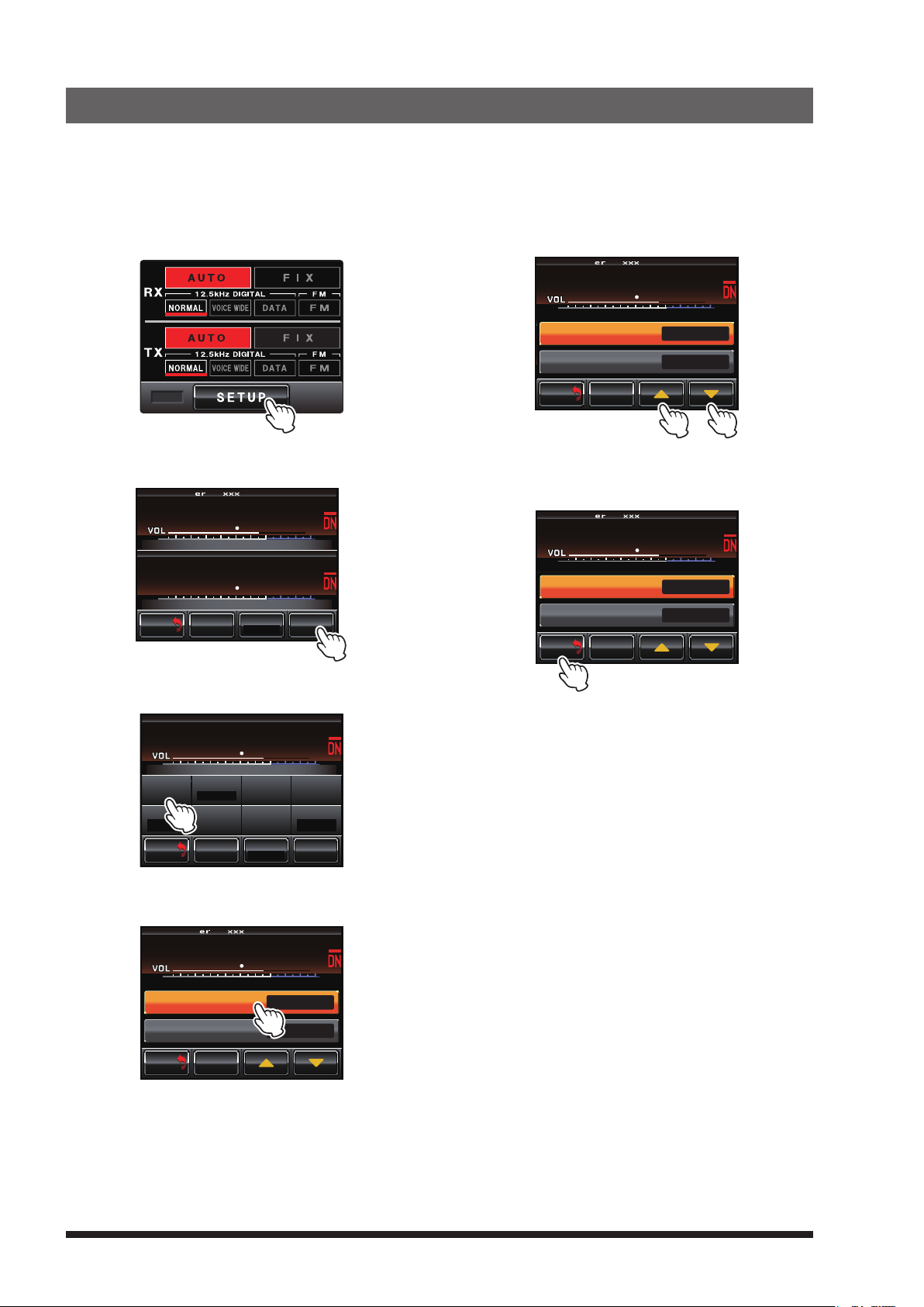
10. Set Up Various Functions
Using the setup menu, the various functions of the repeater can be customized to match the desired applications.
Items to be adjusted can be selected from the respective lists, and the settings entered or selected that are
appropriate for the intended repeater operation.
1 Touch [SETUP] on the operation mode screen.
The setup mode screen will appear.
REMOTE
2 Touch [F].
The setup menu will appear.
SETUP Ver.1.xxx EXP A1
L
P
N
U
PANEL1.XX DSP4.XX
DO
BACK
BACK
KI
L
WN
M/V SQL
8
7
N
KI
7
3
Tx P W R
HI
F
5 Touch [▲] or [▼], or touch the item repeatedly.
The set value will change each time it is touched.
SETUP Ver.1.xxx EXP A1
L
P
N
U
DO
BACK
BACK
KI
8
7
L
N
WN
TONE SQL FRE Q
DCS CODE 023
M/V SQL
KI
Tx P W R
LO
.021 3
Hz
F
6 Touch [BACK].
The setting is determined and the display will
return to the setup menu.
SETUP Ver.1.xxx EXP A1
L
P
N
U
DO
BACK
BACK
KI
8
7
L
N
WN
TONE SQL FRE Q
DCS CODE 023
M/V SQL
KI
Tx P W R
LO
.021 3
Hz
F
3 Touch the menu item.
The menu list will appear.
SETUP
L
P
N
U
DO
R-OFF
T-OFF
BACK
BACK
WN
SQL
M/V SQL
KI
8
ID MO D E
L
N
KI
DG-ID
MODE/REMOTE
7
TIMER
ID SET
Tx P W R
HI
ID AN NO U NCE
DEVIATION
4 Touch the item to be set.
The item will turn orange in color.
SETUP Ver.1.xxx EXP A1
L
P
N
U
DO
BACK
BACK
KI
8
7
L
N
WN
TONE SQL FRE Q
DCS CODE 023
M/V SQL
KI
Tx P W R
LO
.001 0
WIDE
F
Hz
F
24
Page 27
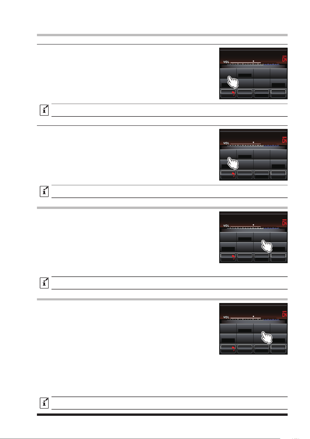
Setting the tone signals for analog FM mode
Setting the tone frequency
1 Touch [SETUP]
2 Touch [SIGNALING], then touch [TONE SQL FREQ].
3 Touch [▲] or [▼].
The set value will change each time [▲] or [▼] is touched.
4 Touch [BACK] 3 times.
The setting is determined and the display will return to the operation
mode screen.
z Factory default: 100.0 Hz
z Tone frequencies between 67.0 Hz and 254.1 Hz can be selected.
Setting the DCS code
1 Touch [SETUP
2 Touch [SIGNALING], then touch [DCS CODE].
3 Touch [▲] or [▼].
The set value will change each time [▲] or [▼] is touched.
4 Touch [BACK] 3 times.
The setting is determined and the display will return to the operation
mode screen.
then touch
]
, then touch
[F].
[F].
SETUP
P
U
WN
DO
SQL
R-OFF
T-OFF
BACK
M/V SQL
BACK
SETUP
P
U
WN
DO
SQL
R-OFF
T-OFF
BACK
M/V SQL
BACK
L
N
L
MODE/REMOTE
L
N
L
MODE/REMOTE
KI
ID MO D E
N
DG-ID
KI
ID MO D E
N
DG-ID
8
KI
8
KI
7
TIMER
ID SET
Tx P W R
HI
7
TIMER
ID SET
Tx P W R
HI
ID AN NO U NCE
DEVIATION
WIDE
F
ID AN NO U NCE
DEVIATION
WIDE
F
z Factory default: 023
z DCS codes between 023 and 754 can be selected.
Setting the TOT (time out timer)
1 Touch [SETUP
]
, then touch
]
, and then touch
[F
[TIMER].
2 Touch [TOT].
The set value will change in the following sequence each time [TOT], [▲],
or [▼] is touched.
à “3 min” à “4 min” à “5 min” à “10 min” à “OFF” à
à “30sec” à “1 min” à “1.5 min” à “2 min” à “2.5 min” à
]
3 Touch [BACK
3 times
.
The setting is determined and the display will return to the operation
mode screen.
Factory default: 3 min
SETUP
P
U
WN
DO
SQL
R-OFF
T-OFF
BACK
M/V SQL
BACK
L
N
L
MODE/REMOTE
KI
ID MO D E
N
DG-ID
8
KI
7
TIMER
ID SET
Tx P W R
HI
Setting the SQL HYSTERESIS
1 Touch [SETUP
]
, then touch
]
, and then touch
[F
[TIMER].
2 Touch [SQL HYSTERESIS].
The set value will change in the following sequence each time [SQL
HYSTERESIS], [▲], or [▼] is touched.
à “NORMAL” à “HIGH” à “MAX” à
NORMAL: The squelch open signal level and the squelch close signal
level are the same.
HIGH: The squelch open signal level is higher than the squelch close
signal level. (Makes squelch less likely to close.)
MAX: The squelch open signal level is much higher than the squelch close level. (Makes squelch even
less likely to close.)
]
3 Touch [BACK
3 times
.
The setting is determined and the display will return to the operation mode screen.
SETUP
P
U
WN
DO
SQL
R-OFF
T-OFF
BACK
M/V SQL
BACK
L
N
L
MODE/REMOTE
KI
ID MO D E
N
DG-ID
8
KI
7
TIMER
ID SET
Tx P W R
HI
ID AN NO U NCE
DEVIATION
WIDE
F
ID AN NO U NCE
DEVIATION
WIDE
F
Factory default: NORMAL
25
Page 28
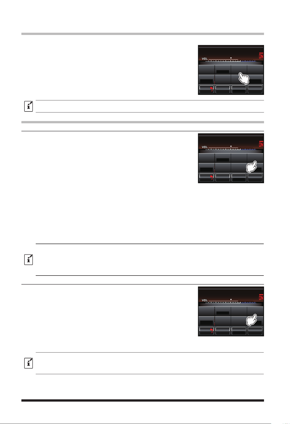
Setting the SQL TAIL LENGTH
Enables setting the time duration of the downlink transmit after the uplink signal ceases.
1 Touch [SETUP
]
, then touch
]
, and then touch
[F
[TIMER].
SETUP
P
U
L
2 Touch [SQL TAIL LENGTH].
The set value will change in the following sequence each time [SQL
TAIL LENGTH], [▲], or [▼] is touched.
à “0ms” à “50ms” à “100ms” à ..................... à “2500ms” à
3 Touch [BACK] 3 times.
The setting is determined and the display will return to the operation
WN
DO
SQL
R-OFF
T-OFF
BACK
M/V SQL
BACK
mode screen.
Factory default: 0ms
Set the ID announcement for analog FM mode
Set the announcement mode
]
1 Touch [SETUP
, then touch
2 Touch [ANNOUNCE
],
then touch [ANNOUNCE MODE].
]
, and then touch
[F
[
ID ANNOUNCE].
The set value will change in the following sequence each time
[
ANNOUNCE MODE], [▲], or [▼] is touched.
à “CW” à “CW wo TONE” à “VOICE”ø à
à “VC wo TONE”ø (VOICE wo TONE) à
ø: Requires optional Voice Guide Unit FVS-2.
SETUP
P
U
WN
DO
SQL
R-OFF
T-OFF
BACK
M/V SQL
BACK
L
N
KI
ID MO D E
L
DG-ID
MODE/REMOTE
N
KI
ID MO D E
L
DG-ID
MODE/REMOTE
8
7
N
KI
TIMER
ID AN NO U NCE
ID SET
Tx P W R
8
7
N
KI
ID SET
Tx P W R
HI
TIMER
HI
DEVIATION
WIDE
ID AN NO U NCE
DEVIATION
WIDE
F
F
3 Touch [ANNOUNCE LEVEL].
The set value will change in the following sequence each time [ANNOUNCE LEVEL], [▲], or [▼] is touched.
à
“HIGH” à “MID” à “LOW” à
4 Touch [CW ID SPEED].
The set value will change in the following sequence each time [CW ID SPEED], [▲], or [▼] is touched.
à “16wd/min” à “20wd/min” à “24wd/min” à “32wd/min” à
5 Touch [BACK] 4 times.
The setting is determined and the display will return to the operation mode screen.
z Factory default:
ANNOUNCE MODE: CW
ANNOUNCE LEVEL: MID
CW ID SPEED: 20wd/min
z When operating in the USA the CW ID SPEED setting time must not exceed 20 words per minute when keyed by an
automatic device, to comply with the FCC rule Part 97: Sec. 97.119 (b)(1) Station identification.
Set announcement time interval
1 Touch [SETUP
]
, then touch
],
and then touch
[F
[
ID ANNOUNCE].
2 Touch [INTERVAL].
The set value will change in the following sequence each time
[
INTERVAL], [▲], or [▼] is touched.
à “OFF” à “3min” à “5min” à “10min” à
à “15min” à “20min” à “30min” à “TOT” à
SETUP
P
U
WN
DO
SQL
R-OFF
T-OFF
BACK
M/V SQL
BACK
L
N
L
MODE/REMOTE
KI
ID MO D E
N
DG-ID
8
KI
7
TIMER
ID SET
Tx P W R
HI
ID AN NO U NCE
DEVIATION
WIDE
F
]
3 Touch [BACK
3 times
.
The setting is determined and the display will return to the operation mode screen.
z Factory default: 10min
z When “CW wo TONE” or “VC wo TONE” on “ANNOUNCE MODE” is set, the time interval is fixed at 10 minutes.
z When operating in the USA, the ID setting time should be ten minutes or less to comply with the FCC rule Part 97:
Sec. 97.119 (a) Station identification.
26
Page 29
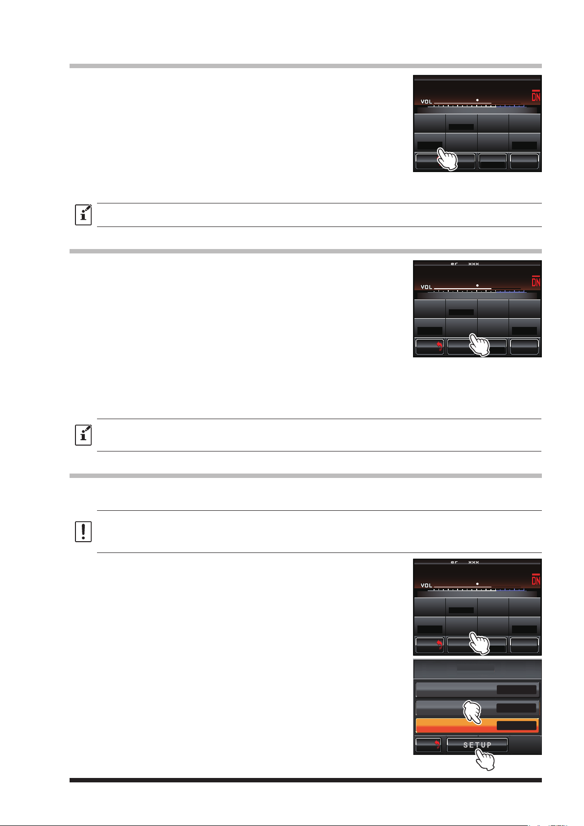
Set the tone signal type for analog FM mode
1 Touch [SETUP
]
, then touch
]
, and then touch
[F
[SQL].
2 Select [RX SQL] to set the tone signal type during reception, or select
[
TX SQL] to set the tone signal type during transmission.
3 Touch [▲] or [▼].
The setting will change in the following sequence each time [▲] or [▼]
is touched.
à “OFF” à “TONE” à “DCS” à
4 Touch [BACK] 3 times.
The setting is determined and the display will return to the operation mode screen.
z Factory default: OFF
z Both TX and RX can be set to different tone signal type.
SETUP
P
U
WN
DO
SQL
R-OFF
T-OFF
BACK
BACK
Setting the display turn-off time
]
1 Touch [SETUP
, then touch
2 Touch [DISPLAY TIMER
]
, and then touch
[F
]
to display “ON” or “OFF”
[MODE/REMOTE].
.
The set value will change between “OFF” and “ON” each time
[
DISPLAY TIMER] is touched.
3 Touch [SETUP].
The display timer setting screen will be displayed.
4 Touch [TIMER].
The set value will change in the following sequence each time [TIMER],
[▲],
or [▼] is touched (Default 1min).
à “1min” à “5min” à “10min” à “30min” à
5 Touch [BACK] 4 times.
The setting is determined and the display will return to the operation mode screen.
z Factory default:
DISPLAY TIMER: ON
TIMER: 1min
SETUP Ver.1.xxx EXP A1
P
U
WN
DO
SQL
R-OFF
T-OFF
BACK
BACK
L
N
KI
ID MO D E
L
N
DG-ID
MODE/REMOTE
M/V SQL
L
N
KI
ID MO D E
L
N
DG-ID
MODE/REMOTE
M/V SQL
8
KI
KI
7
TIMER
ID SET
Tx P W R
HI
TIMER
ID SET
Tx P W R
HI
ID AN NO U NCE
DEVIATION
WIDE
F
ID AN NO U NCE
DEVIATION
WIDE
F
Password
To continue operating the DR-1X when the power is turned ON or after the display has been turned OFF, the
password must be entered.
z Password is factory set to “0000”. It is possible to change the password.
z If you forget your password, you will need to do an all reset. Please note that when all reset is performed, all settings
and memory contents are returned to the factory default state.
z Use the factory default password “0000”, unless it is necessary to change it for management security.
1 Touch [SETUP
]
, then touch
]
, and then touch
[F
[MODE/REMOTE].
2 Touch [DISPLAY TIMER].
3 If [DISPLAY TIMER] is set to “OFF”, touch [DISPLAY TIMER] and turn
it to “ON”.
4 Touch [SETUP].
SETUP Ver.1.xxx EXP A1
L
P
N
U
DO
R-OFF
T-OFF
BACK
BACK
WN
SQL
M/V SQL
KI
ID MO D E
L
N
KI
DG-ID
MODE/REMOTE
TIMER
ID SET
Tx P W R
HI
ID AN NO U NCE
DEVIATION
WIDE
F
REMOTE / COMMAND / DISP TIMER
OFF
REMOTE
COMMAND
DG-ID
DISPLAY TIMER
BACK
M/V
BACK
>
>
>
ON
27
Page 30
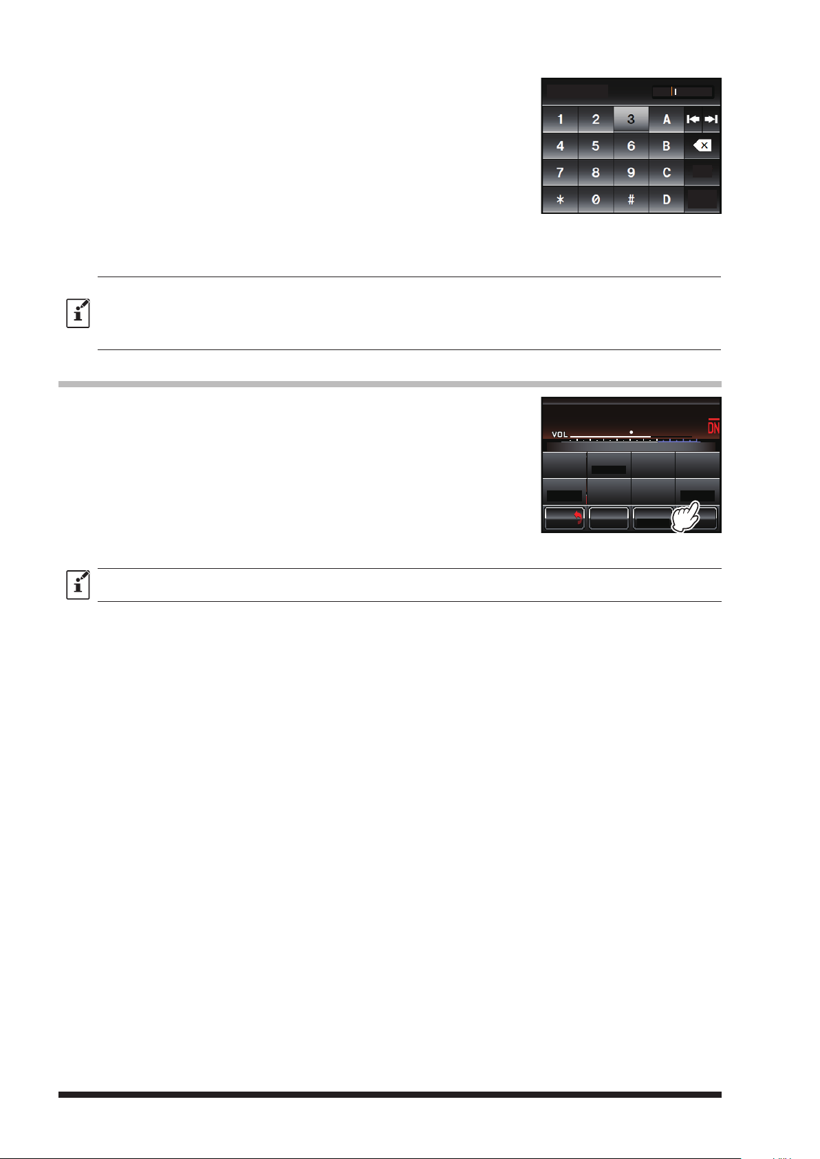
5 Touch [PASSWORD] twice.
The character input screen will appear.
The touched character will be displayed at the top of the screen.
• Four numeric characters can be entered.
• The cursor in the input field moves left or right when [|] or [|] is
touched.
• After completing the input password, the character input screen
automatically disappears and the input password is set.
6 Touch [BACK] 4 times.
The setting is determined and the display will return to the operation
mode screen.
z The password input screen will be displayed when the power is turned ON, or after the display has been turned OFF.
Enter the previously registered 4-digit password (default “0000”).
z To reset the DR-1X, press and hold in the [SETUP] button while turning the transceiver ON à the password input
screen will appear à press and hold the [SETUP] button for 2 seconds à the reset confirmation screen will appear
à touch “OK?”.
Setting the half deviation operation
]
1 Touch [SETUP
2 Touch [DEVIATION] to display “NARROW”.
The setting will toggle between “NARROW” and “WIDE” each time
[
DEVIATION] is touched.
NARROW: Reduces the analog FM/C4FM digital modulation to half.
WIDE: Uses the normal analog FM/C4FM digital modulation.
3 Touch [BACK] twice.
The setting is determined and the display will return to the operation
mode screen.
then touch
[F].
PASSWORD
SETUP
L
P
U
WN
DO
SQL
R-OFF
T-OFF
BACK
M/V SQL
BACK
N
KI
ID MO D E
L
DG-ID
MODE/REMOTE
123
Space
ENT
8
7
N
KI
TIMER
ID AN NO U NCE
ID SET
Tx P W R
HI
DEVIATION
NARROW
F
Factory default: WIDE
28
Page 31
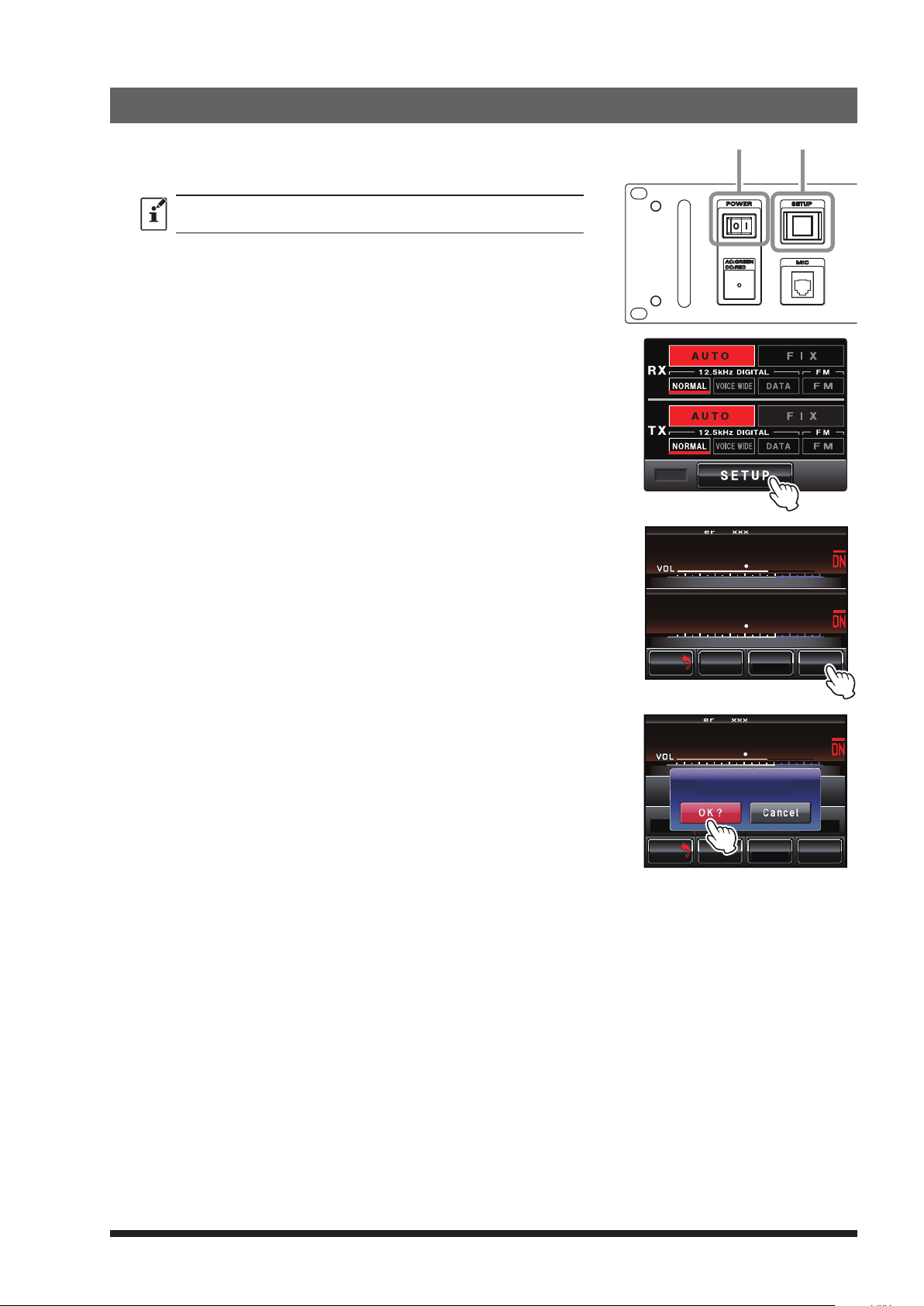
11. Restoring Default Settings (Factory Reset)
SETUPPOWER
1 Turn the DR-1X OFF.
2 Press and hold in the [SETUP] button while turning the repeater
ON.
Continue pressing the [SETUP] button until the operation mode
screen appears on the display.
3 Touch [SETUP].
The setup mode screen will appear.
REMOTE
4 Touch [F] in the setup mode screen.
The setup menu will appear.
5 Touch [F].
The reset confirmation screen will appear.
6 Touch [OK?].
The settings will be reset to the factory default values.
SETUP Ver.1.xxx EXP A1
L
P
N
U
PANEL1.XX DSP4.XX
DO
BACK
BACK
SETUP Ver.1.xxx EXP A1
U
DO
SQL
R-OFF
T-OFF
BACK
BACK
L
WN
M/V SQL
L
P
N
KI
ID MO D E
L
WN
FACTORY RESET
DG-ID
MODE/REMOTE
M/V SQL
KI
8
7
N
KI
7
3
Tx P W R
N
KI
TIMER
ID SET
Tx P W R
HI
HI
ID AN NO U NCE
DEVIATION
WIDE
F
F
29
Page 32
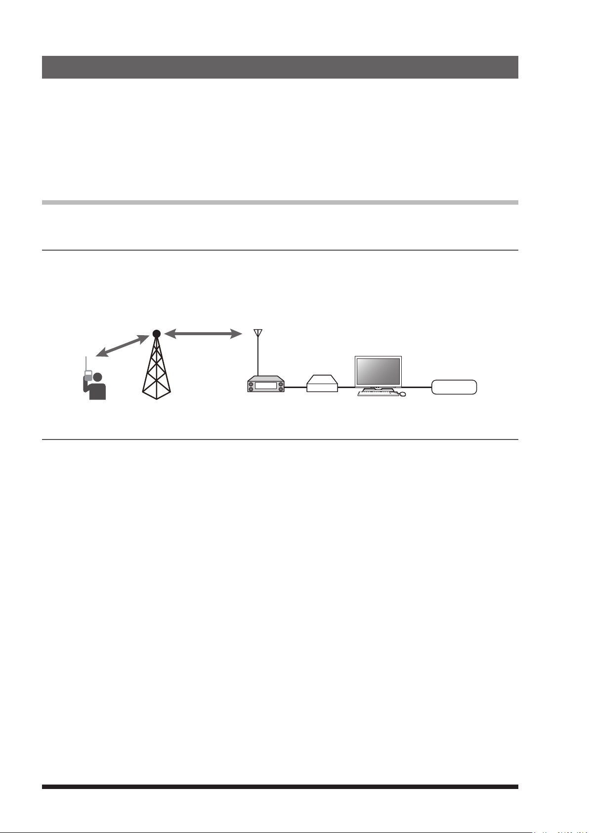
12. Connect to the HRI-200 node station
DR-1X
To use WIRES-X with DR-1X, connect HRI-200 directly to the 10-pin plug on the back of the DR-1X.
Alternatively, there is a method the HRI-200 Node station may be located in a place different from the repeater
site.
Since the repeater site does not normally have a large capacity Internet line, and the HRI-200 must always be
connected to the computer, it may be advantageous to set up the HRI-200 in a different location and uplink it
to the repeater with the Node Station transceiver. It is recommended to downlink and connect to WIRES-X.
For HRI-200 and WIRES-X, please refer to their respective instruction manuals.
RF Link
Link the DR-1X and the node station with the uplink and downlink signals using the DG-ID, WIRES-X may be
operated using the repeater.
Example using the DG-ID “01”:
When the DR-1X and the node station transceiver are set to DG-ID “01”, the downlink signal of the DR-1X is
received only by the node stations with the DG-ID set to “01”. The repeater connects to the Internet when a
signal containing the DG-ID “01” is received on the uplink.
WIRES-X Node Station
Local node
PC
HRI-200
Internet
Setting method
1 Set the DR-1X repeater DG-ID to “01” (see page 14).
2 Set the node station transceiver DG-ID to “01” for both transmit and receive.
For instructions on setting the DG-ID, refer to the transceiver Operating Manual.
3 Set the WIRES-X node station transmit frequency to the uplink frequency of the DR-1X repeater.
4 Set the WIRES-X node station receive frequency to the downlink frequency of the DR-1X repeater.
When the DR-1X repeater is connected to a Node Station with the DG-ID “01”, it downlinks only WIRES-X
signals that include the DG-ID “01”. Communications via the WIRES-X node and the DR-1X repeater are
commenced.
30
Page 33
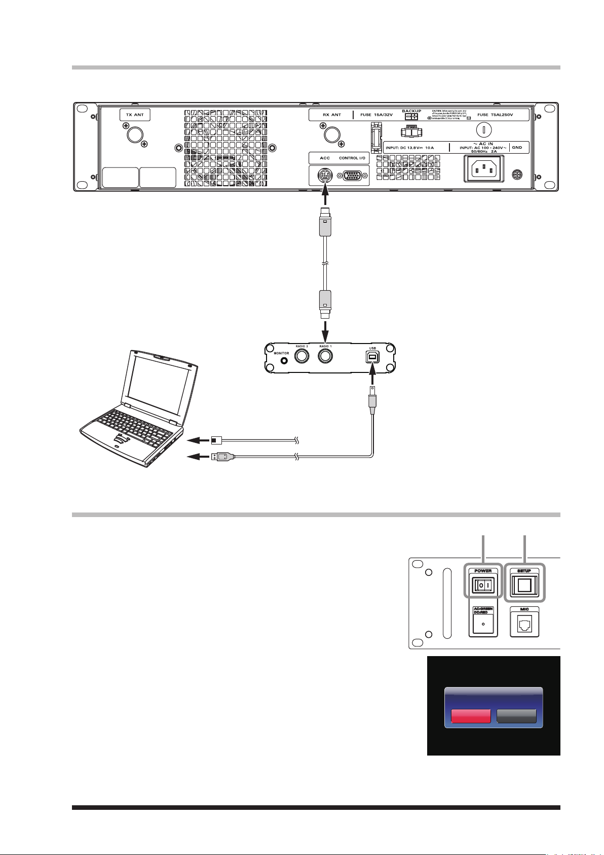
Connecting HRI-200 to DR-1X
SETUPPOWER
The following explains how to connect HRI-200 directly to DR-1X.
10 pin plug
Mini-DIN digital cable
(supplied with HRI-200)
10 pin plug
LAN cable
(sold separately)
To the Internet
Type A plug
USB cable (supplied with HRI-200)
Change the repeater to the HRI mode
1 Turn the DR-1X power OFF.
2 While pressing and holding the [SETUP] button, press the [POWER]
switch.
3 While the “YAESU” logo is being displayed, release the [SETUP]
button.
“HRI+REPEATER MODE” will appear on the display.
4 Touch [OK?
HRI mode will activate.
].
Type B plug
HRI+REPEATER MODE
O K ?
Cance
X
6
-
C
DW
31
Page 34
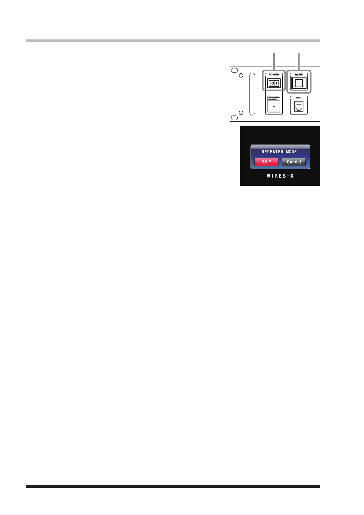
Return to REPEATER mode from HRI mode
SETUPPOWER
E
S
-
XI
RW
O K ?
REPEATER MODE
Cance
1 Turn the DR-1X power OFF.
2 While pressing and holding the [SETUP] button, press the [POWER]
switch.
3 While the “YAESU” logo is being displayed, release the [SETUP]
button.
“REPEATER MODE” will appear on the display.
4 Touch [OK?
The operation mode screen will appear on the display.
].
32
Page 35
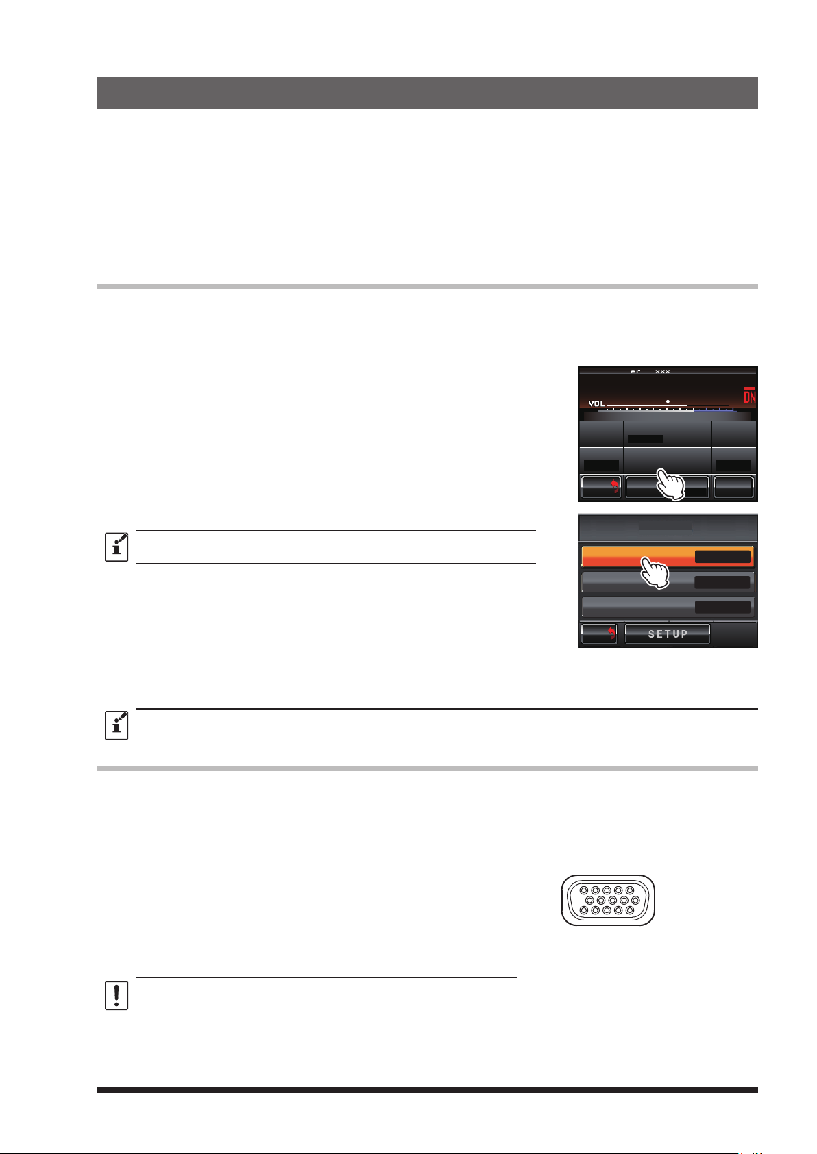
13. Remote Operation with External Controller
5 - 1
10 - 6
15 - 11
Repeater operation may be controlled remotely by connecting an external controller through the [CONTROL
I/O] connector at the back of the repeater.
The following features are available while in remote operation:
• Change the communication mode of repeater transmit and receive
• Turn the RX and TX tone signal “ON” or “OFF”
• Monitor the discriminator analog or demodulated digital audio during up-link reception
To use the repeater under remote control, set up the repeater as explained below, after it is connected to the
external controller.
Turning remote operation ON/OFF
When the remote operation is “ON”, the repeater operates according to the control instructions received from
the external controller (the instructions are received through Pin 11 to Pin 14 of the [CONTROL I/O] connector).
When the remote operation is “OFF”, the repeater operates according to the settings determined through the
setup mode.
1 Touch [SETUP].
The setup mode screen will appear.
2 Touch [F].
The setup menu will appear.
3 Touch [MODE/REMOTE].
The menu list will appear.
4 Touch [REMOTE].
The set value will change between [OFF] and [ON] each time
[
REMOTE] is touched.
z Factory default: OFF
z Remote operation is not available in the “HRI + REPEATER MODE”.
SETUP Ver.1.xxx EXP A1
L
P
N
U
DO
R-OFF
T-OFF
BACK
BACK
WN
SQL
M/V SQL
KI
ID MO D E
L
N
KI
DG-ID
MODE/REMOTE
TIMER
ID SET
Tx P W R
HI
ID AN NO U NCE
DEVIATION
WIDE
F
REMOTE / COMMAND / DISP TIMER
DG-ID
REMOTE
ON
COMMAND
DISPLAY TIMER
BACK
M/V
BACK
5 Touch [BACK] 3 times.
The setting is determined and the display will return to the operation mode screen.
Note that [REMOTE] at the bottom left of the screen is displayed in red.
You can transmit by the microphone and PTT input of the front panel in all settings except AMS/AMS.
Control from external controller
To control the DR-1X remotely, optional cables can be used to connect
the repeater to an external controller.
Use the “CONTROL I/O” connector at the back of the repeater to connect with the external controller.
To interface the DR-1X with an external controller, additional cables
with a 15-pin mini d-sub connector are needed to connect to the
“CONTROL I/O” connector. Your controller may also require rewiring.
Link operation may require four connections: receiver audio, transmitter audio, receiver COR, and transmitter PTT; however, these are not
available on the “CONTROL I/O” connector.
The pin assignment of the “CONTROL I/O” connector is as follows.
CONTROL I/O connector
(as viewed from real panel)
>
>
ON
Do not use a VGA cable for PC display to connect the external controller
to the repeater.
33
Page 36
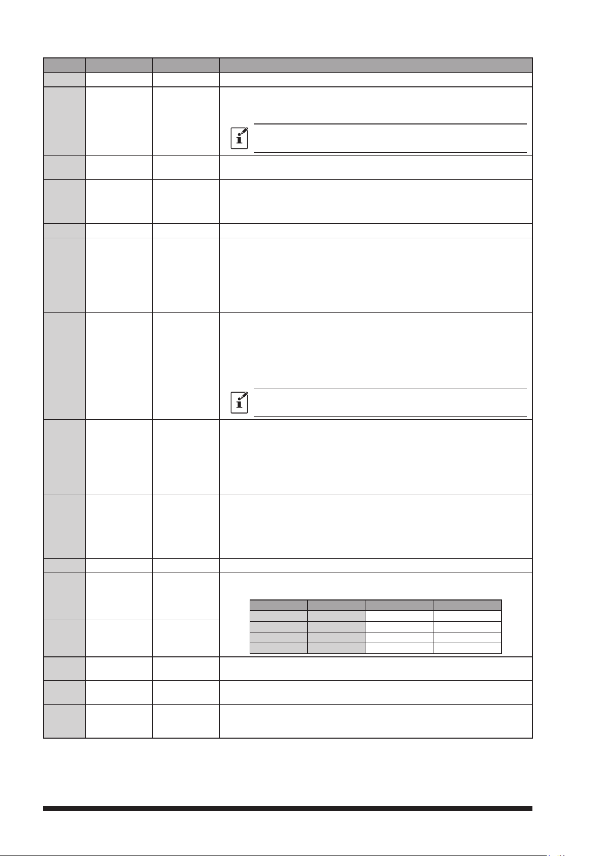
Pin No Pin Name I/O Descriptions
1 EXT I/O Input
[L]
GND: Remote mode [H] OPEN: Repeater mode
[L]
GND: EXT PTT ON [H] OPEN: EXT PTT OFF
When this pin is pulled low by an external device, it keys the repeater
2 PTT Input
3
4
CTCSS/DCS
(PKSQL)
SQL DET
(Noise SQL)
Output
Output
transmitter.
On signaling while controlling the external PTT:
Pin 6 (TONE IN) ... Valid
Pin 7 (AF IN) ... Invalid
[L]
GND: Decoded [H] OPEN: Undecoded
Signaling settings in the repeater setup menu will be applied.
[L]
GND: SQL open [H] OPEN: SQL close
This is an open-collector, active-low output capable of sinking about 10
mA. It indicates that the receiver squelch is open. If the squelch control is
properly set, this indicates a carrier on the receiver channel.
5 GND GND Chassis ground for all logic levels and power supply return
CTCSS/DCS EXT input / 600 ohm, 500 mV peak to peak
Valid during external PTT control
This pin is sub-audible tone input, and has a flat response characteristic
6
TONE IN Input
(repeater deviation is constant for a given signal level over the frequency
range of 5 - 250 Hz). Injecting a too high signal level here causes over-
deviation of CTCSS or DCS, degrading performance.
Use shielded cable to connect to this pin, connecting the shield to GND.
EXT Modulation input / 600 ohm, 1.5 V peak to peak
Valid during external PTT control
This pin is audio input (300 - 3,000 Hz). This audio is injected before the
splatter filter stage, so excess signal input levels are clipped.
7 AF IN Input
It is impossible to input analog modulation signals and convert them to
digital signals on DR-1X.
Use shielded cable to connect to this pin, and connect the shield to GND.
To use the external AF input, set the Pin11/Pin12 EXT port setting to RX: Auto
(AMS) / TX: FM (FIX).
Up-link RX DISC output (w/o de-emphasis), 500 mV peak to peak
Discriminator output during uplink reception. Does not affect the operation
mode of the repeater.
8 DISC OUT Output
Received signals with standard deviation produce 500 mVp-p audio (300
- 3,000 Hz) are output at this pin. The signal is extracted before the de-
emphasis and squelch circuitry. Use shielded cable to connect to this pin,
and connect the shield to GND.
Up-link RX AF output (w/ de-emphasis), 300 mV peak to peak
Analog audio output during uplink reception. Does not affect the operation
9 AF OUT Output
mode of the repeater.
This pin is an output for AF signal (300 mVp-p), being extracted after the
de-emphasis.
Demodulated digital signals can be output as well.
10 GND GND Chassis ground for all logic levels and power supply return
In Remote mode, the logic combination of Ports 1 and 2 determines the
11 EXT port 1
ø
Input
transmit and receive modes as below:
Port 1 Port 2 RX TX
H H Auto (AMS) FM (FIX)
L H FM (FIX) FM (FIX)
12 EXT port 2
ø
Input
H L Digital (FIX) Digital (FIX)
L L Auto (AMS) Auto (AMS)
[L]
13 EXT port 3
14
EXT port 4
ø
Input
ø
Input
GND: RX Tone OFF [H] OPEN: Setup mode
Input a low level signal to indicate that the receiving tone is invalid.
[L]
GND: TX Tone OFF [H] OPEN: Setup mode
Input a low level signal to indicate that the transmitting tone is invalid.
Power supply
15 VCC VCC
This pin provides 13.8V, 2.0A, DC from the repeater supply. There is an
internal 3 A fuse to prevent damage to the repeater.
These functions may only be activated while the repeater is in Remote mode.
ø
34
Page 37
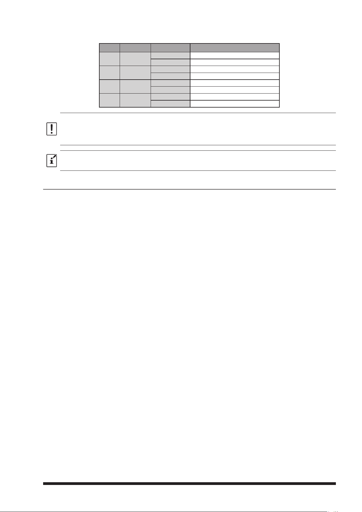
Pins 6, 7, 8, and 9 Functions Controlled by Operation Mode
Pin No Pin Name Receive Mode
6 TONE IN
7 AF IN
8 DISC OUT
9 AF OUT
Even when using the DR-1X with an external controller, the COR, analog and digital IDs, TOT, DCS/CTCSS, TX power, etc.
are already controlled by the DR-1X internal control. These internal controls cannot be disabled. The external controller
must not conflict with these functions. Some functions of the internal controller cannot be overridden.
Before connecting an external controller you must make sure which functions are already internally controlled. Special
precautions must be considered when planning to link with external systems.
z Make sure to switch OFF the power to the radio before connecting the cable.
z In case of jamming or interfering signal while in Repeater mode, Pin 1 may be grounded by external control to temporarily
disable repeating the receiver input.
Digital Invalid
Analog Invalid
Digital Invalid
Analog Invalid
Digital Invalid
Analog Discriminator output
Digital Demodulated digital audio output
Analog Analog audio output
In Repeater / Remote Mode
To use DR-1X in Remote mode
By setting [REMOTE] in the setup menu to ON and inputting a low level to Pin 1 of the [CONTROL I/O]
connector, the repeater may be used in Remote mode and controlled remotely by the external controller. Pins
1, 8, 9, 11, 12, 13 and 14 may be used for input, output and control while in Remote mode.
For details, see “Remote Operation” (see page 33).
35
Page 38
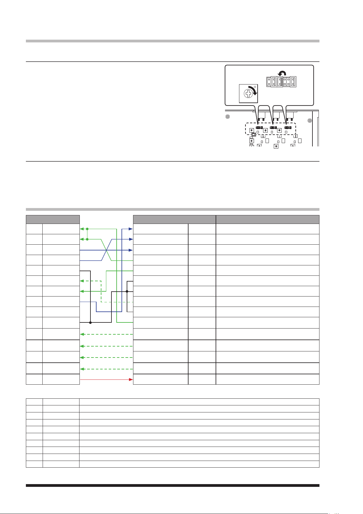
Setting to connect the repeater controller S-COM7330
Set up instructions to interface the Triple Repeater Controller S-COM7330 with the DR-1X.
Modification of S-COM7330
1 Remove the 6 screws from each side and 2 screws from the top
cover of the S-COM7330, then remove the top cover.
2 Change Jumper pin J10C or J11C or J3C and adjust the semi fixed.
AF volume gain up for RX1 or RX2 or RX3.
3 Command Settings.
• Select Path Access Mode: Carrier and CTCSS
• Select COR Filter Delay: 300 msec
• Select Dropout Delay: 0 sec
Setting of DR-1X
Set the DR-1X as follows.
• Setting the communication mode RX: AUTO (AMS)
TX: FM (FIX)
• Setting the tone signals: RX-TONE (100 Hz) (see page 25 and 27)
Connection with S-COM7330 and DR-1X
DR-1X S-COM7330 Connection
pin 1 EXT I/O pin 1 RX Audio Connect to DR-1X AF out
pin 2 EXT PTT pin 2 RX COR Connect to DR-1X SQL DET
CTCSS/DCS DET
pin 3
pin 4 SQL DET pin 4 TX PTT Connect to DR-1X EXT PTT
pin 5 GND pin 5 TX Audio Connect to DR-1X AF in
pin 6 TONE IN pin 6 GND DR-1X GND
pin 7 AF IN pin 7 GND DR-1X GND
pin 8 DISC OUT pin 8 TX pin 8 Select TX LOGIC or TX CTCSS by JP pin
pin 9 AF OUT pin 9 GND DR-1X GND
pin 10 GND
pin 11 EXT PORT1
pin 12 EXT PORT2
pin 13 EXT PORT3
pin 14 EXT PORT4
pin 15 VCC OUT DC jack DC in Connect to DR-1X VCC out
pin 3 CTCSS in Connect to DR-1X CTCSS/DCS decode output
I/O Controller
pin 1 to 6
I/O Controller
pin 1 to 6
I/O Controller
pin 1 to 6
I/O Controller
pin 1 to 6
I/O Controller
pin 1 to 6
Logic output
Logic output
Logic output
Logic output
Logic output
Connect to DR-1X EXT I/O
(needs S-COM programming)
Connect to DR-1X EXT PORT1
(needs S-COM programming)
Connect to DR-1X EXT PORT2
(needs S-COM programming)
Connect to DR-1X EXT PORT3
(needs S-COM programming)
Connect to DR-1X EXT PORT4
(needs S-COM programming)
The wiring paths shown by the dotted lines require programming the S-COM7330.
pin 1 EXT I/O Jumper to pin 2 EXT PTT or connect to S-COM7330 LOGIC OUT (L: EXT I/O enable)
pin 2 EXT PTT EXT PTT input from S-COM7330. It will be controlled by RX COR normally.
CTCSS/DCS DET
pin 3
pin 4 SQL DET Noise SQL decode output (Connect to RX COR)
pin 5 GND GND
pin 6 TONE IN Tone input from S-COM7330 (Connect to TX pin8)
pin 7 AF IN Modulation input from S-COM7330
pin 8 DISC OUT RX audio output without de-emphasis
pin 9 AF OUT RX audio output with de-emphasis
pin 10 GND GND
Signaling decode output (CTCSS/DCS etc)
36
Page 39
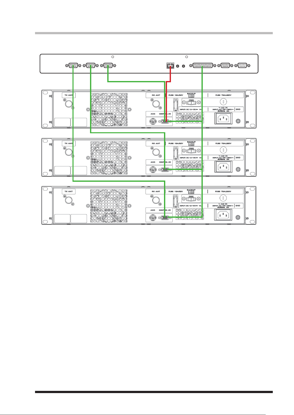
Connecting S-COM7330
S-COM7330
programming of S-COM7330.
Repeater 1
Repeater 2
Repeater 3
+
-
DC 9V-36V
RESETINIT
RS232-1RS232-2IDPORT 1PORT 2PORT 3
This connection needs
37
Page 40
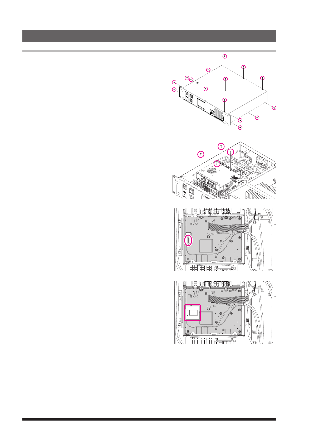
14. Installation of the Optional Accessories
Installing the optional Voice Guide Unit FVS-2
1 Turn the DR-1X
2 Disconnect all the cables from the DR-1X.
3 Remove the 4 screws from each side and 7 screws from the
top cover of the DR-1X, then remove the top cover.
4 Referring to Figure 1, remove the 4 screws from the top
cover of the RX-UNIT, then remove the top cover.
[
POWER] switch to “OFF”.
Figures in this page show the outline of the DR-1X.
5 Refer to Figure 2 for the mounting location for the FVS-2.
6 Push the FVS-2 (component side up) onto the pins corresponding
to its assigned mounting location on the RX-UNIT.
Gently press the FVS-2 down until it is firmly seated on the
connector.
Figure 1
Figure 2
Figure 3
7 Replace the top cover of the RX-Unit and 4 screws.
8 Replace the top cover of the DR-1X and 15 screws.
38
Page 41
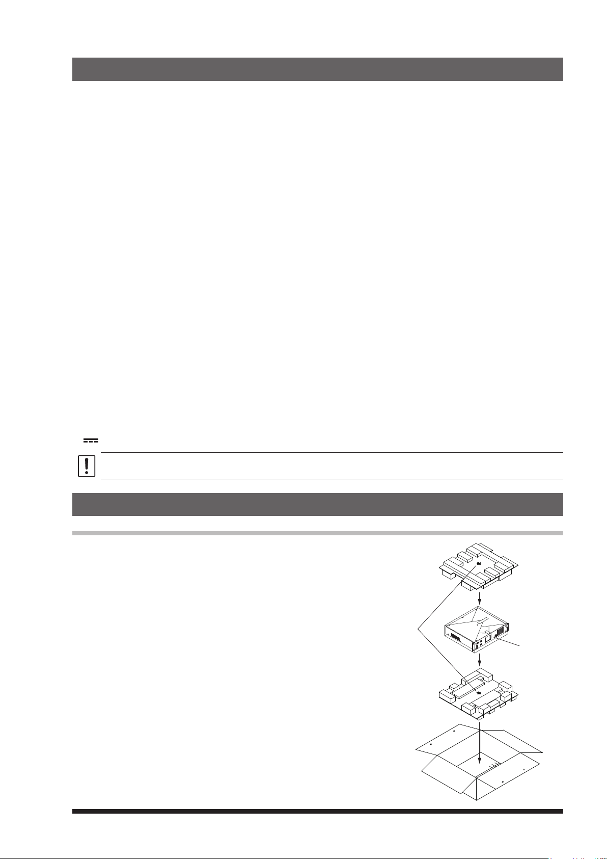
15. Specications
Arrow Mark
side up
zGeneral
Frequency range : 144 to 146 MHz, 430 to 440 MHz or 144 to 148 MHz, 430 to 450 MHz
Channel steps : 5 / 6.25 kHz
Emission type : F1D, F2A, F2D, F3E, F7W
Frequency stability : ±2.5 ppm (−4°F to +140°F (−20°C to +60°C))
Antenna impedance : 50 Ω
Supply voltage : AC 100-240V (DR-1X only)
Current consumption : AC: 2 A (max) (@ 117 V Input) (DR-1X only)
Operating temperature : DR-1X: −4°F to +140°F (−20°C to +60°C)
Dimensions : 19" (W) × 3.5" (H) × 15" (D) (482 × 88 × 380 mm) w/o knob, connector, handle
Weight (approx.) : DR-1X: 22.05 lbs (10 kg)
zTransmitter
RF power output : 50 / 20 / 5 W
Modulation type : F1D, F2A, F2D, F3E Variable Reactance Modulation
Spurious emission : At least 60 dB below
zReceiver
Circuit type : Double conversion super-heterodyne
Intermediate frequencies : 1st: 47.25 MHz, 2nd: 450 kHz
Receiver sensitivity :
Adjacent Channel Selectivity : Better than 65 dB TYP (20 kHz offset)
Selectivity : FM 12 kHz/35 kHz (−6 dB/−60 dB)
Intermodulation : Better than 65 dB TYP (20 /40 kHz offset)
Audio output : 4 W (4 Ω, THD 10%, 13.8 V; internal speaker)
z Symbols placed on the equipment
Direct current
16K0F1D F1D 16K0F2D F2D - Frequency modulation data transmission, using a modulating subcarrier
16K0F3E F3E - Frequency modulation telephony
12K5F7W F7W - Two or more digital channels combinations of the above
DC 11.7 to 15.8 V, negative grounding
DC: 1.5 A (receive)
10 A (50 W TX, 144 MHz / 430 MHz band)
DR-1XE: −20°C to +55°C
DR-1XE: 8.8 kg
F7W 4FSK (C4FM)
0.3 μV (Digital 144 MHz Band/430 MHz Band) BER 1 %
0.2 μV (FM 144 MHz Band/430 MHz Band) 12 dB SINARD
Frequency modulation data transmission, double sideband, without using a modulating subcarrier
z Rated values are at normal temperature and pressure.
z Ratings and specifications are subject to change without notice for product improvement reasons.
16. After-market Services
Contact Yaesu Service Center for non-warranty repairs
Repairs will be made at the user’s expense if normal functions can
be maintained after the repair. Please check with the retail store or
Yaesu service center for more information.
Front Panel
39
Page 42

YAESU LIMITED WARRANTY
Limited Warranty is valid only in the country/region where this product was originally purchased.
On-line Warranty Registration:
Thank you for buying YAESU products! We are confident your new radio will serve your needs for many years! Please
register your product at www.yaesu.com - Owner’s Corner
Warranty Terms:
Subject to the Limitations of the Warranty and the Warranty Procedures described below, YAESU MUSEN hereby warrants
this product to be free of defects in materials and workmanship in normal use during the “Warranty Period.” (the “Limited
Warranty”).
Limitations of Warranty:
A. YAESU MUSEN is not liable for any express warranties except the Limited Warranty described above.
B. The Limited Warranty is extended only to the original end-use purchaser or the person receiving this product as a gift,
and shall not be extended to any other person or transferee.
C. Unless a different warranty period is stated with this YAESU product, the Warranty Period is three years from the date
of retail purchase by the original end-use purchaser.
D. The Limited Warranty is valid only in the country/region where this product was originally purchased.
E. During the Warranty Period, YAESU MUSEN will, at its sole option, repair or replace (using new or refurbished
replacement parts) any defective parts within a reasonable period of time and free of charge.
F. The Limited Warranty does not cover shipping cost (including transportation and insurance) from you to us, or any
import fees, duties or taxes.
G. The Limited Warranty does not cover any impairment caused by tampering, misuse, failure to follow instructions supplied
with the product, unauthorized modifications, or damage to this product for any reasons, such as: accident; excess
moisture; lightning; power surges; connection to improper voltage supply; damage caused by inadequate packing or
shipping procedures; loss of, damage to or corruption of stored data; product modification to enable operation in another
country/purpose other than the country/purpose for which it was designed, manufactured, approved and/or authorized;
or the repair of products damaged by these modifications.
H. The Limited Warranty applies only to the product as it existed at the time of the original purchase, by the original retail
purchaser, and shall not preclude YAESU MUSEN from later making any changes in design, adding to, or otherwise
improving subsequent versions of this product, or impose upon YAESU MUSEN any obligation to modify or alter this
product to conform to such changes, or improvements.
I. YAESU MUSEN assumes no responsibility for any consequential damages caused by, or arising out of, any such defect
in materials or workmanship.
J. TO THE FULLEST EXTENT PERMITTED BY LAW, YAESU MUSEN SHALL NOT BE RESPONSIBLE FOR ANY
IMPLIED WARRANTY WITH RESPECT TO THIS PRODUCT.
K. If the original retail purchaser timely complies with the Warranty Procedures described below, and YAESU MUSEN
elects to send the purchaser a replacement product rather than repair the “original product”, then the Limited Warranty
shall apply to the replacement product only for the remainder of the original product Warranty Period.
L. Warranty statutes vary from state to state, or country to country, so some of the above limitations may not apply to your
location.
Warranty Procedures:
1. To find the Authorized YAESU Service Center in your country/region, visit www.yaesu.com. Contact the YAESU Service
Center for specific return and shipping instructions, or contact an authorized YAESU dealer/distributor from whom the
product was originally purchased.
2. Include proof of original purchase from an authorized YAESU dealer/distributor, and ship the product, freight prepaid, to
the address provided by the YAESU Service Center in your country/ region.
3. Upon receipt of this product, returned in accordance with the procedures described above, by the YAESU Authorized
Service Center, all reasonable efforts will be expended by YAESU MUSEN to cause this product to conform to its original
specifications. YAESU MUSEN will return the repaired product (or a replacement product) free of charge to the original
purchaser. The decision to repair or replace this product is the sole discretion of YAESU MUSEN.
Other conditions:
YAESU MUSEN’S MAXIMUM LIABILITY SHALL NOT EXCEED THE ACTUAL PURCHASE PRICE PAID FOR THE
PRODUCT. IN NO EVENT SHALL YAESU MUSEN BE LIABLE FOR LOSS OF, DAMAGE TO OR CORRUPTION OF
STORED DATA, OR FOR SPECIAL, INCIDENTAL, CONSEQUENTIAL, OR INDIRECT DAMAGES, HOW EVER CAUSED;
INCLUDING WITHOUT LIMITATION TO THE REPLACEMENT OF EQUIPMENT AND PROPERTY, AND ANY COSTS OF
RECOVERING, PROGRAMMING OR REPRODUCING ANY PROGRAM OR DATA STORED IN OR USED WITH THE
YAESU PRODUCT.
Some Countries in Europe and some States of the USA do not allow the exclusion or limitation of incidental or consequential
damages, or a limitation on how long an implied warranty lasts, so the above limitation or exclusions may not apply. This
warranty provides specific rights, there may be other rights available which may vary between countries in Europe or from
state to state within the USA.
This Limited Warranty is void if the label bearing the serial number has been removed or defaced.
40
Page 43
This equipment has been tested and found to comply with the limits for a Class B digital device, pursuant to Part
15 of the FCC Rules. These limits are designed to provide reasonable protection against harmful interference in a
residential installation. This equipment generates, uses and can radiate radio frequency energy and, if not installed
and used in accordance with the instructions, may cause harmful interference to radio communications. However,
there is no guarantee that interference will not occur in a particular installation.
If this equipment does cause harmful interference to radio or television reception, which can be determined by
turning the equipment off and on, the user is encouraged to try to correct the interference by one or more of the
following measures:
Reorient or relocate the receiving antenna.
r
Increase the separation between the equipment and receiver.
r
Connect the equipment into an outlet on a circuit different from that to which the receiver is connected.
r
Consult the dealer or an experienced radio/TV technician for help.
r
This device complies with part 15 of the FCC Rules. Operation is subject to the following two conditions: (1) This
device may not cause harmful interference, and (2) this device must accept any interference received, including
interference that may cause undesired operation.
EU Declaration of Conformity
We, Yaesu Musen Co. Ltd of Tokyo, Japan, hereby declare that this radio equipment DR-1XE is in full compliance with
EU Radio Equipment Directive 2014/53/EU. The full text of the Declaration of Conformity for this product is available to
view at http://www.yaesu.com/jp/red
ATTENTION – Conditions of usage
This transceiver works on frequencies that are regulated and not
permitted to be used without authorisation in the EU countries shown
in this table. Users of this equipment should check with their local
spectrum management authority for licensing conditions applicable for this
equipment.
AT BE BG CY CZ DE
DK ES EE FI FR UK
GR HR HU IE IT LT
LU LV MT NL PL PT
RO SK SI SE CH IS
LI NO – – – –
Disposal of Electronic and Electrical Equipment
Products with the symbol (crossed-out wheeled bin) cannot be disposed as household waste.
Electronic and Electrical Equipment should be recycled at a facility capable of handling these items
and their waste by-products.
Please contact a local equipment supplier representative or service center for information about the
waste collection system in your country.
Page 44

Copyright 2017
YAESU MUSEN CO., LTD.
All rights reserved.
No portion of this manual may be
reproduced without the permission of
YAESU MUSEN CO., LTD.
YAESU MUSEN CO., LTD.
Tennozu Parkside Building
2-5-8 Higashi-Shinagawa, Shinagawa-ku, Tokyo 140-0002 Japan
YAESU USA
6125 Phyllis Drive, Cypress, CA 90630, U.S.A.
YAESU UK
Unit 12, Sun Valley Business Park, Winnall Close
Winchester, Hampshire, SO23 0LB, U.K.
1712I-AS
Printed in Japan
 Loading...