

Page 1

CPV350
GPS Chart Plotter
with VHF FM Marine Transceiver
OWNER'S MANUAL
Page 2

WARNING!!!
Electronic charts displayed by the CPV350 are believed to be accurate and reliable,
but that are not intended to be a substitute for the official charts, which should remain
your main reference for all matters related to the execution of safe navigation.
For this reason we would like to remind you that you should carry on board and use
the official published and approved nautical charts.
FCC NOTICE
This equipment has been tested and found to comply with the limits for a Class A
digital device, pursuant to part 15 of the FCC Rules. These limits are designed to
provide reasonable protection against harmful interference when the equipment is
operated in a commercial environment. This equipment generates, uses, and can
radiate radio frequency energy and, if not installed and used in accordance with the
instruction manual, may cause harmful interference to radio communications.
Operation of this equipment in a residential area is likely to cause harmful
interference in which case the user will be required to correct the interference at his
own expense.
Unauthorized changes or modifications to this equipment may void compliance with
NOTICE
FCC Rules. Any change or modification must be approved in writing by Marine
Division of Vertex Standard.
Page 2 CPV350
Page 3

Congratulations on you purchase of the CPV350C GPS Chart Plotter with VHF FM Marine
Transceiver!
Whether this is your first GPS chartplotter, or if you have other STANDARD HORIZON
equipment, the STANDARD HORIZON organization is committed to ensuring your enjoyment of this GPS chartplotter. STANDARD HORIZON technical support personnel stand
behind every product we sell, and our Product Support team invites you to contact us should
you require technical advice or assistance, at 800/767-2450.
CAUTION
The GPS chartplotter is designed for maritime use. Please give attention to avoid
water intrusion into the C-MAP NT
+
/MAX C-CARD cartridge holder.
Extensive exposure to heat may result in damage to the GPS chartplotter.
The GPS chartplotter contains dangerous high voltage circuits which only expe-
rienced technicians can handle.
STANDARD HORIZON will not be liable for errors contained herein, or for
incidental or consequential damages in connection with the performance or use
of this material.
CLEANING PROCEDURE FOR THE CHARTPLOTTER SCREEN
Cleaning of the chartplotter screen is a very important and must be done carefully.
Since the surface is covered by a antireflective coating, the procedure for cleaning
all the surfaces can be performed using the following procedure: You need a soft
tissue or towel and a cleaning spray (Windex) containing Isopropanol (a normal
spray cleaner sold for a PC screen, for example PolaClear by Polaroid). Fold the
tissue or lens tissue into a triangular shape, moisten the tip and use the index finger
behind a corner to move the tissue across the surface, in overlapping side to side
strokes. If the tissue is too wet, a noticeable wet film will be left in its path and you
will need to repeat the process. If too dry, the tissue won’t glide easily, and may
damage the surface.
Page 3CPV350
Page 4

TABLE OF CONTENTS
1. INTRODUCTION .......................................................................................................................... 8
1.0 GENERAL INFORMATION .............................................................................................. 8
1.1 PACKING LIST.................................................................................................................9
1.1.0 Packing List ........................................................................................................ 9
1.2 OPTIONAL ACCESSORIES ............................................................................................ 9
1.3 SAFETY / WARNING INFORMATION ........................................................................... 10
1.3.0 VHF Marine Antenna Installation ...................................................................... 10
1.3.1 ON-LINE Warranty Registaration ..................................................................... 10
1.3.2 Product Support Inquires .................................................................................. 10
1.4 FCC RADIO LICENSE INFORMATION ......................................................................... 11
1.4.0 Station License ................................................................................................. 11
1.4.1 Radio Call Sign ................................................................................................ 11
1.4.2 Canadian Ship Station Licensing ..................................................................... 11
2. GETTING STARTED .................................................................................................................. 12
3. C-MAP MAX OVERVIEW ........................................................................................................... 24
4. MAP FUNCTIONS ...................................................................................................................... 26
5. DATA FUNCTION ....................................................................................................................... 30
6. CONTROLS AND INDICATORS ................................................................................................ 32
1.4.3 FCC / Industry Canada Information ................................................................. 11
2.0 MOUNTING THE GPS CHARTPLOTTER ..................................................................... 12
2.1 BRACKET MOUNTING .................................................................................................. 12
2.2 FLUSH MOUNTING ....................................................................................................... 13
2.3 CONNECTIONS ............................................................................................................ 14
2.3.0 Rear Panel Connections .................................................................................. 14
2.3.1 VHF Antenna .................................................................................................... 15
2.3.2 Selecting a Marine VHF Antena ....................................................................... 15
2.3.3 Coaxial Cable ................................................................................................... 16
2.3.4 Optional Enhanced Second VHF/PA Station .................................................... 17
2.3.5 NMEA Connections .......................................................................................... 19
2.3.6 Outputting NMEA to a Personal Computer ...................................................... 19
2.3.7 Serial PC Connection ....................................................................................... 19
2.3.8 Outputting GPS Coordinates ............................................................................ 20
2.3.9 NMEA Data Page ............................................................................................. 20
2.4 GPS ANTENNA .............................................................................................................. 21
2.4.0 Mounting the GPS WAAS Smart Antenna........................................................ 21
2.4.1 Mounting on a Pole .......................................................................................... 21
2.4.2 Flush Mounting ................................................................................................. 21
2.4.3 PA Horn Connections ....................................................................................... 22
2.5 SMART GPS CONNECTOR TABLE .............................................................................. 22
2.6 BATTERY CONNECTIONS ........................................................................................... 22
2.7 OPTIONAL BLACK BOX FISH FINDER ........................................................................ 23
2.8 OPTIONAL VHF EXTERNAL SPEAKER ....................................................................... 23
3.0 INTRODUCTION ........................................................................................................... 24
3.1 INSERTING THE C-CARD ............................................................................................ 25
4.0 NEW MAX FUNCTIONS MENU .................................................................................... 26
4.0.0 Zoom Type ........................................................................................................ 26
4.0.1 Fonts & Symbols .............................................................................................. 26
4.0.2 Perspective View .............................................................................................. 27
4.0.3 Dynamic Nav-Aids ............................................................................................ 27
4.0.4 Safety Status Bar (DSI - Data Safety Indicator) ............................................... 28
4.0.5 Currents Prediction ........................................................................................... 29
5.0 PICTURES & DIAGRAMS ............................................................................................. 30
5.0.0 How to show the pictures or diagrams of a Multimedia Object ........................ 31
5.1 ENHANCED PORT INFO .............................................................................................. 31
6.0 CONTROLS AND CONNECTIONS ............................................................................... 32
6.1 GETTING STARTED ...................................................................................................... 33
6.1.0 Power On, Off and ShuttlePoint knob operation .............................................. 33
6.1.1 Cursor Vs. Home Mode .................................................................................... 34
6.1.2 Cursor and Menu selection speed .................................................................... 35
6.1.3 Changing the Ships Icon .................................................................................. 35
6.1.4 Changing the backlight and contrast ................................................................ 36
6.1.5 Selecting North Up or Course Up ..................................................................... 36
6.2 ADJUSTING THE TIME ................................................................................................. 37
Page 4 CPV350
Page 5

6.3 SELECTING LORAN TD OR OTHER COORDINATE SYSTEM ................................... 38
6.4 CHANGING THE CHART COLOR ................................................................................ 39
6.5 SELECTING PAGES USING SOFT KEYS .................................................................... 39
6.6 CUSTOMIZING THE SOFT KEYS ................................................................................. 40
6.7 OTHER SETTINGS IN GENERAL SETUP MENU ........................................................ 40
6.8 INFORMATION PAGE.................................................................................................... 41
7. USING FIND SERVICES & MORE FUNCTION ........................................................................ 42
7.0 PORT SERVICES .......................................................................................................... 42
7.1 OTHER AVAILABLE SEARCHES .................................................................................. 42
7.2 INFO ON LAKES ............................................................................................................ 43
7.2.0 Quick Info On Lakes ......................................................................................... 43
8. CREATING MARKS ................................................................................................................... 45
9. MAN OVER BOARD (MOB) FUNCTION .................................................................................. 50
10. ROUTES ..................................................................................................................................... 51
11. TRACKS ..................................................................................................................................... 55
12. USER C-CARD .......................................................................................................................... 58
13. PAGES ....................................................................................................................................... 60
7.2.1 Full Info On Lakes ............................................................................................ 43
8.0 CREATING A NEW MARK USING THE CHART PAGE ................................................ 45
8.1 EDITING a MARK .......................................................................................................... 45
8.1.0 Deleting a Mark or Waypoint ............................................................................ 46
8.1.1 Moving a Mark or Waypoint .............................................................................. 46
8.2 MARKS/WAYPOINTS LIST ........................................................................................... 47
8.3 Creating a NEW MARK with the MARKS/WAYPOINTS LIST ....................................... 47
8.4 GOTO CURSOR ............................................................................................................ 48
8.5 GOTO MARK ................................................................................................................. 49
9.0 DELETING A MOB POINT ............................................................................................. 50
10.0 CREATING A ROUTE USING WAYPOINTS ................................................................. 51
10.1 MAKING ADDITIONAL ROUTES ................................................................................... 52
10.2 CREATING A ROUTE USING MARKS ON THE CHART PAGE ................................... 52
10.3 INSERTING A WAYPOINT INTO A ROUTE .................................................................. 53
10.4 GOTO A ROUTE ............................................................................................................ 53
10.4.0 By select Route ................................................................................................ 53
10.4.1 By Cursor key ................................................................................................... 53
10.5 OTHER SETTINGS IN ROUTE MENU .......................................................................... 54
11.0 TRACKING ..................................................................................................................... 55
11.0.0 Saving and starting a new Track ...................................................................... 56
11.0.1 Other Settings in Track Menu ........................................................................... 56
11.1 USING THE TRIP LOG .................................................................................................. 57
11.1.0 Resetting the Trip Log ...................................................................................... 57
12.0 USER C-CARD MENU .................................................................................................. 58
12.0.0 Formatting the User C-CARD .......................................................................... 58
12.0.1 Transferring files to the optional User C-CARD ............................................... 59
12.0.2 Loading a file .................................................................................................... 59
12.0.3 Deleting a file from the User C-CARD ............................................................. 59
13.0 CHART PAGE ................................................................................................................ 61
13.0.0 Window Selections ........................................................................................... 61
13.0.1 Additional Functions on Chart page ................................................................. 62
13.0.2 Turning Off Information on Icon Points............................................................. 62
13.0.3 Display Mode .................................................................................................... 62
13.0.4 Marine Settings ................................................................................................ 63
13.0.5 Depth Settings .................................................................................................. 63
13.0.6 Land Settings ................................................................................................... 64
13.0.7 Chart Settings ................................................................................................... 64
13.0.8 Underwater Objects Settings ............................................................................ 64
13.0.9 Customizing the Data Windows ....................................................................... 65
13.1 CUSTOMIZING CHART SETTINGS .............................................................................. 65
13.2 NAVIGATION PAGE ....................................................................................................... 66
13.3 HIGHWAY PAGE ............................................................................................................ 67
13.4 CELESTIAL PAGE ......................................................................................................... 67
13.5 GPS STATUS PAGE ...................................................................................................... 68
13.6 NMEA DISPLAY PAGE................................................................................................... 68
13.7 NMEA DATA PAGE ........................................................................................................ 69
13.8 NMEA DEPTH, WIND SPEED, TEMP AND SOG TREND PAGES ............................... 69
13.9 VHF DIGITAL SELECTIVE CALLING ............................................................................ 70
13.9.0 Position Request .............................................................................................. 70
Page 5CPV350
Page 6

14. ADVANCED SETTINGS ............................................................................................................. 71
14.0 NAVIGATE ...................................................................................................................... 71
14.1 COMPASS ...................................................................................................................... 72
14.2 INPUT/OUTPUT (NMEA) ............................................................................................... 72
14.3 ALARMS ........................................................................................................................ 72
15. AIS .............................................................................................................................................. 74
15.0 AIS SYSTEM DEFINITIONS .......................................................................................... 74
15.1 AIS MENU ...................................................................................................................... 75
15.2 TO SET THE CHARTPLOTTER FOR RECEIVING AIS ................................................ 75
15.3 QUICK INFO ON AIS TARGET ...................................................................................... 76
16. C-MAP WEATHER SERVICE .................................................................................................... 77
16.0 C-WEATHER SERVICE MENU ..................................................................................... 77
16.0.0 Download ......................................................................................................... 77
16.0.1 Copy From User C-CARD ................................................................................ 78
16.0.2 Weather Forecast ............................................................................................. 88
17. RADIO CONTROLS AND INDICATORS ................................................................................... 79
18. BASIC RADIO OPERATION ...................................................................................................... 82
19 DIGITAL SELECTIVE CALLING ................................................................................................ 94
16.0.3 Real Time View ................................................................................................ 88
17.0 CONTROLS AND KEYS ................................................................................................ 79
17.1 RECEIVER AUDIO TONE CONTROL ........................................................................... 81
18.0 RECEPTION .................................................................................................................. 82
18.1 TRANSMISSION ............................................................................................................ 82
18.2 TRANSMIT TIME-OUT TIMER (TOT) ............................................................................ 82
18.3 SIMPLEX/DUPLEX CHANNEL USE .............................................................................. 82
18.4 INTERNATIONAL, USA, AND CANADA MODE ............................................................ 83
18.5 NOAA WEATHER CHANNELS...................................................................................... 83
18.5.1 NOAA Weather Alert ........................................................................................ 83
18.5.2 NOAA Weather Alert Test ................................................................................. 84
18.5.3 Customizing NOAA Weather Alert ................................................................... 84
18.6 EMERGENCY CHANNEL (CHANNEL 16 USE) ............................................................ 84
18.7 CALLING ANOTHER VESSEL (CHANNEL 16 OR 9) ................................................... 85
18.8 MAKING TELEPHONE CALLS ...................................................................................... 85
18.9 OPERATING ON CHANNELS 13 AND 67 ..................................................................... 86
18.10 DUAL WATCH (TO PRIORITY CHANNEL) ................................................................... 86
18.11 SCANNING .................................................................................................................... 86
18.11.0 Selecting the Scan Type ................................................................................... 86
18.11.1 Memory Scanning (M-SCAN) ........................................................................... 87
18.11.2 Priority Scanning (P-SCAN) ............................................................................. 87
18.11.3 Priority Channel Set ......................................................................................... 88
18.12 PA/FOG OPERATION .................................................................................................... 89
18.12.0 Operating the PA HAIL mode ........................................................................... 89
18.12.1 Operating the FOG HORN mode ..................................................................... 89
18.12.2 FOG ALERT TONE Frequency ........................................................................ 91
18.13 INTERCOM OPERATION .............................................................................................. 91
18.14 VOICE SCRAMBLER ..................................................................................................... 92
18.14.0 Setting Up the Voice Scrambler ....................................................................... 92
18.14.1 Voice Scramble Operation ............................................................................... 93
19.0 GENERAL ...................................................................................................................... 94
19.1 MARITIME MOBILE SERVICE IDENTITY (MMSI) ........................................................ 94
19.1.0 What is an MMSI? ............................................................................................ 94
19.1.1 Programming the MMSI ................................................................................... 95
19.2 DSC Distress Call .......................................................................................................... 95
19.2.0 Transmitting a DSC Distress Call ..................................................................... 95
19.2.1 Receiving a DSC Distress Call ........................................................................ 97
19.3 ALL SHIPS CALL ........................................................................................................... 97
19.3.0 Transmitting an All Ships Call ........................................................................... 97
19.3.1 Receiving an All Ships Call .............................................................................. 98
19.4 INDIVIDUAL CALL ......................................................................................................... 98
19.4.0 Setting up the Individual / Position Call Directory ............................................ 98
19.4.1 Setting up Individual Reply ............................................................................... 99
19.4.2 Setting up the Individual/Group Call Ringer ................................................... 100
19.4.3 Transmitting an Individual Call ....................................................................... 101
19.4.4 Receiving an Individual Call ........................................................................... 102
19.5 CALL WAITING DIRECTORY ...................................................................................... 103
Page 6 CPV350
Page 7

19.5.0 Enabling the Call Waiting Feature .................................................................. 103
19.5.1 Reviewing Received Calls Logged into the Call Waiting Directory ................ 103
19.5.2 To Delete the Received Log from the “DSC Log" Directory ........................... 104
19.6 GROUP CALL .................................................................................................................. 105
19.6.0 Setting up a Group Call .................................................................................. 105
19.6.1 Transmitting a Group Call .............................................................................. 106
19.6.2 Receiving a Group Call .................................................................................. 107
19.7 POSITION REQUEST .................................................................................................. 107
19.7.0 Setting up Position Reply ............................................................................... 107
19.7.1 Transmitting a Position Request to Another Vessel ....................................... 108
19.7.2 Receiving a Position Request ........................................................................ 110
19.8 POSITION SEND ......................................................................................................... 110
19.8.0 Setting up a Position Send Ringer ................................................................. 110
19.8.1 Transmitting a DSC Position Send Call ......................................................... 111
20. RADIO SETUP ......................................................................................................................... 113
21. ENHANCED RAM+ MIC OPERATION .................................................................................... 115
22. VH-310 HANDSET OPERATION .............................................................................................. 119
23. MAINTENANCE ....................................................................................................................... 126
24. CHANNEL ASSIGNMENTS ..................................................................................................... 128
25. TECHNICAL TESTS ................................................................................................................ 134
26. WARRANTY ............................................................................................................................. 136
27. SPECIFICATIONS .................................................................................................................... 140
28 APENDIX: TERMS ................................................................................................................... 142
19.8.2 Receiving a DSC Position Send Call ............................................................. 112
20.0 CHANNEL NAME CHANGE ........................................................................................ 113
20.1 UNIT NAME ................................................................................................................. 114
21.0 RAM+ MIC CONTROLS .................................................................................................. 115
21.1 PA/FOG OPERATION ................................................................................................. 116
21.1.0 Operating the PA / Hailer .................................................................................. 116
21.1.1 Operating the FOG Horn .................................................................................. 117
21.2 INTERCOM OPERATION ............................................................................................ 117
21.2.0 Communication ................................................................................................ 117
21.2.1 Calling .............................................................................................................. 117
21.3 DSC/RADIO SETUP MODE ........................................................................................ 118
22.0 VH-310 HANDSET CONTROLS .................................................................................. 119
22.1 PA/FOG OPERATION .................................................................................................. 122
22.1.0 Operating the PA / Hailer .................................................................................. 122
22.1.1 Operating the FOG Horn .................................................................................. 122
22.2 INTERCOM OPERATION ............................................................................................ 111
22.2.0 Communication ................................................................................................ 122
22.2.1 Calling .............................................................................................................. 123
22.3 MANUAL INPUTTING OF THE GPS LOCATION (LAT/LON) ..................................... 123
22.4 DSC/RADIO SETUP MODE ........................................................................................ 124
22.4.1 Changing GPS Information to Vessel position or COG.................................... 125
22.4.2 External Speaker AF Selection ........................................................................ 125
23.0 REPLACEMENT PARTS.............................................................................................. 126
23.1 FACTORY SERVICE .................................................................................................... 127
23.2 TROUBLESHOOTING ................................................................................................. 127
25.0 SYSTEM TEST ............................................................................................................ 134
25.0.0 RAM Menu (reset) .......................................................................................... 134
25.0.1 DIM Menu ....................................................................................................... 134
25.0.2 Cartridges ....................................................................................................... 135
25.0.3 Serial Ports ..................................................................................................... 135
25.0.4 Modem test ..................................................................................................... 135
26.0 MARINE PRODUCTS LIMITED WARRANTY ............................................................. 136
26.1 ON-LINE WARRANTY REGISTRATION ..................................................................... 138
27.0 CPV350 SPECIFICATIONS ......................................................................................... 140
27.0.0 GENERAL ...................................................................................................... 140
27.0.1 TRANSMITTER .............................................................................................. 140
27.0.2 RECEIVER ..................................................................................................... 140
27.0.3 GPS CHART PLOTTER ................................................................................. 140
27.1 GPS WAAS SMERT RECEIVER SPECIFICATIONS .................................................. 141
27.1.0 PHYSICAL CHARACTERSTICS .................................................................... 141
27.1.1 ELECTRICAL CHARACTERSTICS ............................................................... 141
27.1.2 GPS PERFORMANCE ................................................................................... 141
Page 7CPV350
Page 8

1. INTRODUCTION
1.0 GENERAL INFORMATION
The CPV350 is a WAAS GPS chart plotter, Class D DSC 25 W VHF with a powerful 30 W
loud hailer capable of listen-back, fog signaling, bells, whistles integrated one box. The
CPV350 has 2 connections for CMP25 RAM+ or VH-310 telephone style handset second
stations. Connect the optional FF520, and the CPV350 becomes a full function 50/200 kHz
fish finder shown on the high-resolution sunlight viewable 16:9 aspect ratio Wide Screen
display in a full page or a split Chart/fish screen. Rotary knobs make features easy to access
along with the unique ergonomically designed handgrip for sure control. Featuring Class D
Additional features include, dual watch, programmable scan, priority scan dedicated 16/9
and WX key, noise-canceling microphone with channel selection, back lit front panel keys
and LCD and a optional voice scrambler.
GPS chart plotter features include:
7-inch 256-Color TFT sunlight viewable LCD display (Screen Resolution: 800x480)
12 Channel GPS WAAS smart antenna
Cartography: C-Map NT+, C-Map MAX capable
Customizable display windows
Dual frequency fish finder capable (FF520 required)
Split screen capability
Worldwide background map showing detail up to 2.0 NM included
Stores 1000 user waypoints
NMEA data pages
Marine VHF features include:
Commercial grade ITU Class D VHF transceiver
Complete Digital Selective Calling (DSC).
Full position request and send functions
CLEAR VOICE noise reduction microphone with 16/9 key and channel selection
Tri-station capability (RAM+ and/or VH-310 required)
30W loud hailer with listen back, 4 foghorns, bells, and whistles
Oversized rotary channel selector
Channel name capability
Display repeats GPS information (when attached to GPS)
User Programmable Scan, Priority Scan, and Dual Watch
Fully adjustable backlighting and LCD contrast
Voice scrambler (optional)
Page 8 CPV350
Page 9

1.1 PACKING LIST
When the package containing the GPS chartplotter is first opened, please check for the
following contents.
If any parts are missing contact the dealer this GPS chartplotter was purchased from.
Accessories and replacement parts may be ordered from STANDARD HORIZON’s Parts
Department at 562/404-2700 Ext. 351 or via the web at www.standardhorizon.com.
1.1.0 Packing List
CPV350 GPS Chart Plotter with VHF FM Marine Transceiver
GPS WAAS Smart antenna
Microphone
Dust Cover
DC Power Cable
Accessory Cable
Flush Mount hardware, Mounting Bracket, and mounting hardware
Owner’s Manual
1.2 OPTIONAL ACCESSORIES
Black Box Fish Finder
FF520 - Dual Frequency Black Box Fish Finder
Hailing horns
External Speakers
Second Station Remote Microphones
(500W or 1000W depending on transducer connected)
500W Transducers
DST520 - Nylon depth temp
DST521 - Transom mount depth, temp speed
DST523 - Bronze depth temp
DST525 - In-hull depth only
DST526 - Thruhull Depth, speed, temp with fairing block
1000W Transducers
DST527 - In-hull depth only
DST528 - Bronze thru-hull depth temp
220SW - 5 inch round horn (small)
240SW - 5x7 horn
MLS-300 - VHF Extension speaker
MLS-310 - VHF Extension 10W amplified speaker
CMP25 - RAM+ Microphone
VH-310 - Telephone Style Handset
CT-100 - 23-feet Extension Cable for Second Station Remote Microphone
Scrambler
CVS2500
Page 9CPV350
Page 10

1.3 SAFETY / WARNING INFORMATION
This radio is restricted to occupational use, work related operations only where the radio
operator must have the knowledge to control the exposure conditions of its passengers and
bystanders by maintaining the minimum separation distance of 0.6 m (2 feet). Failure to
observe these restrictions will result in exceeding the FCC RF exposure limits.
1.3.0 VHF Marine Antenna Installation
The antenna must be located at least 0.6 m (2 feet) away from passengers in order to comply
with the FCC RF exposure requirements.
1.3.1 On-Line Wattanty Registration
Please visit www.standardhorizon.com to register the CPV350 Marine VHF. It should be
noted that visiting the Web site from time to time may be beneficial to you, as new products
are released they will appear on the Marine Division of Vertex Standard Web site.
1.3.2 Product Support Inquiries
If you have any questions or comments regarding the use of the CPV350, you can visit the
Marine Division of Vertex Standard Web site to send an E-Mail or contact the Product
Support team at 800-767-2450 M-F 7:00- 5:00PST.
Page 10 CPV350
Page 11

1.4 FCC RADIO LICENSE INFORMATION
Vertex Standard radios comply with the Federal Communication Commission (FCC)
requirements that regulate the Maritime Radio Service.
1.4.0 Station License
An FCC ship station license is no longer required for any vessel traveling in U.S. waters
(except Hawaii) which is under 20 meters in length. However, any vessel required carrying
a marine radio on an international voyage, carrying a HF single side band radiotelephone
or marine satellite terminal is required to have a ship station license. FCC license forms,
including applications for ship (506) and land station licenses can be downloaded via the
Internet at www.fcc.gov/forms. To obtain a form from the FCC, call (888) 225-5322.
1.4.1 Radio Call Sign
Currently the FCC does not require recreational boaters to have a Ship Radio Station
License. The USCG recommends the boats registration number and the state to be used.
1.4.2 Canadian Ship Station Licensing
You may need a license when traveling in Canada. If you do need a license contact the
nearest field office or regional office or write:
Industry Canada
Radio Regulatory Branch
Attn: DOSP
300 Slater Street
Ottawa, Ontario
Canada, KIA 0C8
1.4.3 FCC / Industry Canada Information
The following data pertaining to the transceiver is necessary to fill out the license
application.
Type Acceptance ........................................................................................... FCC Part 80
Output Power ................................................................. 1 Watt (low) and 25 Watts (high)
Emission ........................................................................................... 16K0G3E, 16K0G2B
Frequency Range ....................................................................... 156.025 to 163.275 MHz
FCC Type Number ...................................................................................... K6630163X3S
Industry Canada Type Approval .............................................................. 511B-30163X3S
Page 11CPV350
Page 12
2. GETTING STARTED
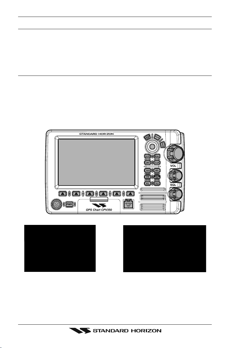
2.0 MOUNTING THE GPS CHARTPLOTTER
The CPV350 is supplied with hardware for bracket or flush mounting. Below are pictures
showing actual examples of the two types of installation.
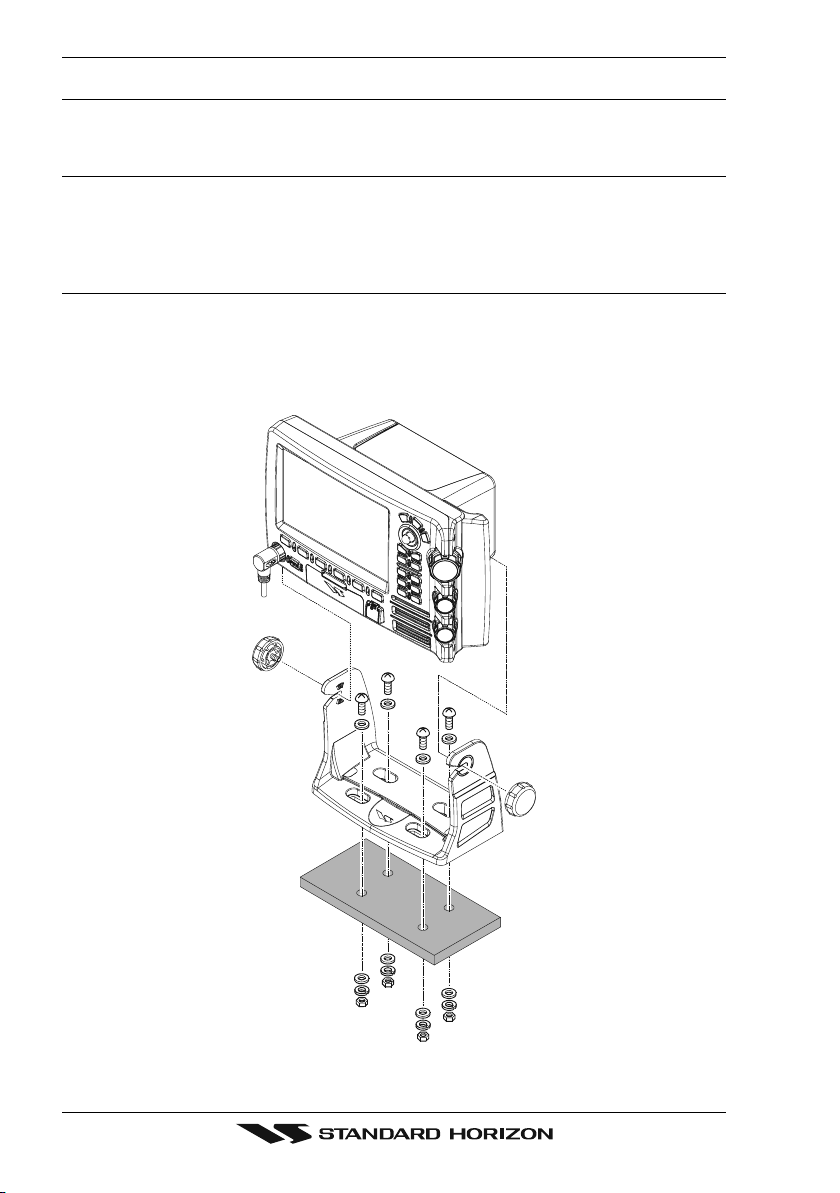
2.1 BRACKET MOUNTING
The CPV350 can be mounted using the supplied bracket. Before installing ensure the area
the CPV350’s bracket is mounted to is strong enough to support the weight of the CPV350
especially while under way.
After the location is found, attach the mounting base to the area using the supplied hardware.
Figure 2.1 - Installing CPV350 (Bracket)
Page 12 CPV350
Page 13
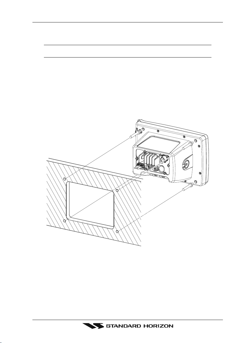
2.2 FLUSH MOUNTING
The CPV350 is supplied with a flush mount template for the cutout hole and screw holes
required to install the CPV350.
NOTE
Before drilling holes ensure there are no obstructions behind the location that could interfere with
the mounting and there is physically enough room to mount the CPV350.
1. After a location is found, peal the template label from the backing and apply the label
to the mounting area.
2. Drill a hole in one area of the cut area that will allow the blade of a jig saw to be inserted.
Insert and cut out the area on the panel using the jig saw.
3. Remove the three screws affiex the grip and remove the grip from the CPV350.
4. Next drill the four holes required to insert the CPV350 with the mounting studs.
5. Install the mounting studs on the CPV350 and insert into the mounting hole.
6. Attach the CPV350 to the mounting location by attaching the supplied hardware to the
mounting studs.
Figure 2.2 - Installing CPV350 (Flush)
Page 13CPV350
Page 14
2.3 CONNECTIONS
The CPV350 has a cable or connectors that are used to connect the CPV350 to Power
Supply, to the GPS WAAS Smart antenna, optional FF520 50/200kHz BLACK BOX FISH
FINDER and to NMEA devices such as VHF's, digital instruments and autopilots as shown
in the image below:
External
PA
Horn
FF520
Fish Finder
GPS
Antenna
VHF
Antenna
CPV350
Figure 2.4 Installing the GPS WAAS Smart antenna
Speaker
Autopilot
2.3.0 Rear Panel Connections
1. VHF ANTENNA JACK
Connects an antenna to the transceiver. Use a marine VHF antenna with impedance
of 50 ohms.
2. REMOTE MIC CONNECTORS
Connects to the enhanced RAM+ MIC (Remote Access Microphone) or the VH-310
Handset.
3. ACCESSORY CONNECTION
Allows connection of optional FF520 fish finder module and connections for AIS receiver
and other NMEA devices.
4. GPS Antenna
Connects the GPS antenna to the CPV350. Only use the GPS Smart antenna supplied
with the CPV350
5. External speaker
Connects to the MLS-300, MLS-310 or any 8 Ohm 6Watt external speaker
6. PA Horn
Connects to 220SW, 240SW or any 4 Ohm 30W PA Speaker
7. DC INPUT CABLE
Connects the radio to a DC power supply capable of delivering 12V DC.
Page 14 CPV350
Page 15

1
2
3
4
5
6
7
Figure 2.5 CPV350 Rear Panel
2.3.1 VHF Antenna
ABOUT VHF RADIO
The radio frequencies used in the VHF marine band lie between 156 and 158 MHz with some
shore stations available between 161 and 163 MHz. The marine VHF band provides
communications over distances that are essentially “line of sight” (VHF signals do not travel
well through objects such as buildings, hills or trees). Actual transmission range depends
much more on antenna type, gain and height than on the power output of the transmitter.
On a fixed mount 25W radio transmission expected distances could be greater than 15
miles.
2.3.2 Selecting a Marine VHF Antenna
Marine antennas are made to radiate signals equally in all horizontal directions, but not
straight up. The objective of a marine antenna is to enhance the signal toward the horizon.
The degree to which this is accomplished is called the antenna’s gain. It is measured in
decibels (dB) and is one of the major factors in choosing an antenna. In terms of effective
radiated power (ERP), antennas are rated on the basis of how much gain they have over
a theoretical antenna with zero gain. A 3-foot, 3dB gain antenna represents twice as much
gain over the imaginary antenna. Typically a 3-foot 3dB gain stainless steel whip is used on
a sailboat mast. The longer 8-foot 6dB fiberglass whip is primarily used on powerboats that
require the additional gain.
Page 15CPV350
Page 16
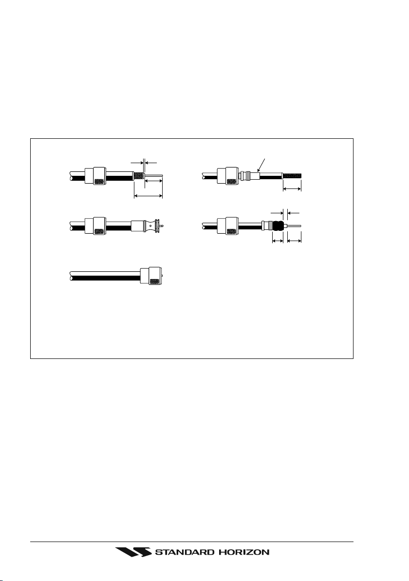
2.3.3 Coaxial Cable
VHF antennas are connected to the transceiver by means of a coaxial cable - a shielded
transmission line. Coaxial cable is specified by its diameter and construction. For runs less
than 20 feet, RG-58/U, about 1/4 inch in diameter is a good choice. For runs over 20 feet
but less than 50 feet, the larger RG-8X should be used for cable runs over 50 feet RG213
should be used. For installation of the connector onto the coaxial cable refer to the figure
below. Figure 2.4.0 Installing the VHF antenna To get your coax cable through a fitting and
into your boat's interior, you may have to cut off the end plug and reattach it later. You can
do this if you follow the directions that come with the connector. Be sure to make good
soldered connections.
1/16''
3/4''
1 1/ 8''
Figure 2.4.0 Installing the VHF antenna
Adapter
3/4''
1/8''
5/8''3/8''
To get your coax cable through a fitting and into your boat’s interior, you may have
to cut off the end plug and reattach it later. You can do this if you follow the
directions that come with the connector. Be sure to make good soldered
connections.
Page 16 CPV350
Page 17
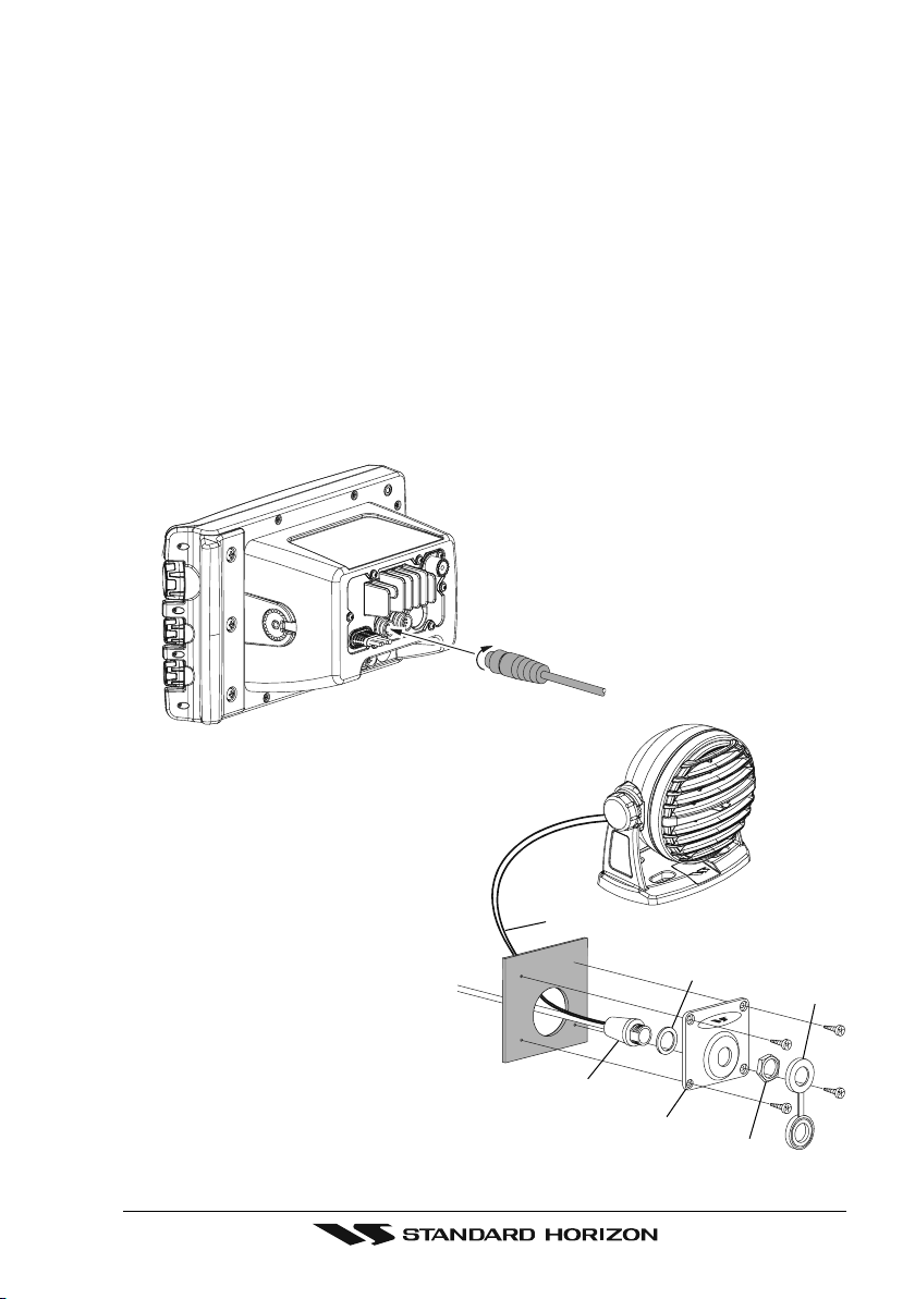
2.3.4 Optional Enhanced Second VHF/PA Station
INSTALLATION
The CPV350 is capable of using up to 2 Enhanced RAM+ mics or VH-310 Handset to
remotely control the Radio, DSC, and Distress functions. In addition the CPV350 can
operate as a full function intercom system.
1. Connect the Routing Cable to the one of the Remote Mic eight pin connector on the rear
panel, then tighten the Cable Nut.
2. Referring to Figure 3, make a 1.2” (30 mm) hole in the wall, then insert the Routing Cable
into this hole. Connect the Gasket and Mount Base to the Routing Cable Connector
using the Nut.
3. Drill the four Screw holes (approx. 2 mm) on the wall then install the Mounting Base to
the wall using four screws.
4. Put the Rubber Cap on to the Nut. The installation is now complete.
5. Wires for an external speaker are provided on the Routing Cable. Connect any 8 Ohm
external speaker. When connected the RAM+ (or VH-310 Handset) controls the volume
level of this speaker.
Wall
External Speaker Connections
Gasket
Cap
Routing Cable
Mounting Bracket
Nut
Page 17CPV350
Page 18
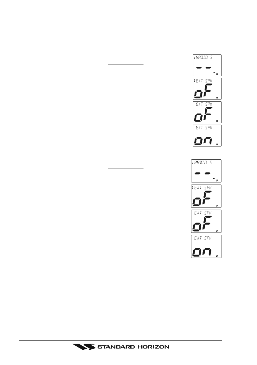
Remote Mic or External Speaker Selection
By default the RAM+ or VH-310 Handset internal speaker is turned on, however using the
RAM+ mic (or VH-310 Handset) this speaker can be turned off so the external speaker can
be used.
RAM+ mic procedure
1. Press and hold the [CALL/SET] key.
2. Press the [] or [] key to select
RADIO SETUP.
3. Press the [CALL/SET] key.
4. Press the [] key to until
EXT SPK is shown and press the [CALL/SET]
key.
5. Press the [] or [] key to select
oF (External speaker off) or on
(External speaker on).
6. Press the [CALL/SET] key to save the selection.
7. Press the [16/9] key to exit this mode.
VH-310 Procedure
1. Press and hold the [CALL(MENU)] key.
2. Press the [] or [] key to select
RADIO SETUP.
3. Press the [ENT] key
4. Press the [] key to until
5. Press the [] or [] key to select
EXT SPK is shown and press the [ENT] key.
oF (External speaker off) or on
(External speaker on).
6. Press the [ENT] key to save the selection.
7. Press the [16/9] key to exit this mode.
Page 18 CPV350
Page 19
2.3.5 NMEA Connections
NOTE
The CPV350 can send many sentences to external NMEA devices. The NMEA output wires are
Brown and White and the NMEA Common is Green. If you have connected devices as shown in
the below table and need to feed NMEA to other devices (Autopilot, Radar ....) you can parallel wires
from the Brown or White wires.
Pin Wire Color Description Connection Example Additional Information
1 Black -- - No Connection
2 Red -- - No Connection
3 Green NMEA Common Common for NMEA devices
4 Blue NMEA Input Port 1 Conncect to output of NMEA device Default is NMEA0183
5 Brown NMEA Output Port 1 Conncect to intput of NMEA device Default is NMEA0183 with GLL. RMB, RMC, and XTE sentences
6 Gray NMEA Input Port 2 Conncect to output of NMEA device Default is NMEA0183
7 White NMEA Output Port 2 Conncect to intput of NMEA device Default is NMEA0183 with GLL. RMB, RMC, and XTE sentences
8 Yellow NMEA Output Port 4 Connect autopilot Default is NMEA0183 with APA. APB, XTE, COG, and BOD sentences
: When the FF520 is connected, port 2 input must be changed to “FF520.” To do this, press [MENU] two times, move the ShuttlePoint konb to highlight
ADVANCED SETUP, IN/OUT CONNECTIONS, PORT2 INPUT, FF520.
Figure 2.3.5 IN/OUT CONNECTION menu
2.3.6 Outputting NMEA to a Personal Computer
The CPV350 can be connected to output Marks, Routes, and tracks to many PC programs
available in the aftermarket. To send or receive User Points the PC Program must be able
to receive NMEA WPL and RTE sentences.
2.3.7 Serial PC Connection
Outputting Waypoints and Routes
The CPV350 can be connected to output Marks, Routes and tracks to many PC programs
available in the aftermarket. To send or receive User Points the PC Program must be able
to receive NMEA WPL and RTE sentences.
PC DB9 Connection CPV350 Connection
Pin 2 Brown wire
Pin 3 Blue
Pin 4 Green
Page 19CPV350
Page 20

2.3.8 Outputting GPS Coordinates
Some PC programs use NMEA sentences from a GPS to show position. The CPV350
outputs GLL, RMB and RMC.
PC DB9 Connection CPV350 Connection
Pin 2 Brown wire
Pin 4 Green
2.3.9 NMEA Data Page
The NMEA Data Page is very useful to see if an External device (example: Depth Sounder)
is transmitting NMEA sentences to the GPS chart plotter. This page can also be used to see
if the GPS chart plotter NMEA output is being loaded down by an external NMEA device
Example:
Autopilot connected but the CPV350 but is not receiving NMEA data.
Usually the Autopilot will be connected to the yellow wire.
To check to see if the GPS chart plotter is transmitting the Autopilot sentences:
1. Press [MENU]. Move the ShuttlePoint knob to highlight
[ENT].
2. Move the ShuttlePoint knob to highlight
3. The
NMEA DATA page is shown.
DATA and press [ENT].
4. Connect the Blue Wire on the GPS chartplotter to the junction of the yellow wire and the
autopilot. The display should look similar to the picture below.
5. If no data is shown press the [ZOOM] and move the knob on right side up to change
port.
NMEA DISPLAY and press
Page 20 CPV350
Page 21

2.4 GPS ANTENNA
CUTTING TEMPLATE
2.4.0 Mounting the GPS WAAS Smart Antenna
The CPV350 is supplied with a 12 Channel GPS WAAS Smart antenna. This antenna is
designed to be mounted on a base, installed on an extension or even flush mounted.
Choose a location for the antenna that has a clear view of the sky and is not located within
3 FT of Radar or other transmitting antenna. Ensure there are no major obstructions or
fixtures in the immediate proximity to the antenna. The antenna relies on direct “line of sight”
satellite reception. If you are unsure of the chosen location, temporarily mount the antenna
in the desired location to verify correct operation. If mounted close to Radar, and after the
GPS chartplotter has a fix, turn on the Caps on RADAR to ensure the GPS chartplotter holds
the fix (use the GPS Status Page).
2.4.1 Mounting on a Pole
The thread used on the antenna is an industry standard (1 inch 14TPI) used on a wide range
of mounting brackets. Due to the manufacturing process of these mounting brackets you
may see some slop when tightening down the antenna to the bracket. This is no concern
however as the antenna must be tightened until the antenna stops rotating.
NOTE
The antenna cable can be cut and spliced to ease installation. Care must be taken when
reconnecting the antenna cable to protect from water and corrosion.
2.4.2 Flush Mounting
NOTE
Before drilling holes, it is recommended the antenna be positioned where the location is planned
to be drilled, cable connected to the CPV350 and the CPV350 turned on to ensure a GPS fix is
received.
1. Remove the threaded base from the antenna dome.
2. To ease installation a flush mounting template for the antenna has been included.
3. Apply the mounting template sticker to the area that was verified for GPS reception.
4. Then, drill out the 0.63” (16 mm) and 0.16” (4 mm) holes, and remove the template.
5. Insert the cable into the 0.63” (16 mm) hole and route to the CPV350.
6. Apply a small amount or RTV to the under side of the antenna.
7. Place the antenna and then screw it into place using the screws. In some cases the
screw may not be long enough, if this happens simply apply more RTV to the underside
of the antenna to glue it into place.
CUTTING TEMPLATE
16 mm [0.63"] or greater
0
4 mm [0.155"]
0
Figure 2.4.2 Installing the GPS WAAS Smart antenna
4 mm [0.155"]
0
4 mm [0.155"]
0
GPS OVERALL SHAPE
Page 21CPV350
Page 22

2.4.3 PA Horn Connections
The CPV350 can be connected to the 220SW or 240SW PA horn to hail other vessels or
send FOG, bells or whistles.
2.5 SMART GPS CONNECTOR TABLE
Pin Wire Color Description Connection Example
1 Red Battery Positive Connect to Battery Positive and Red wire of GPS Antenna
2 Green Smart GPS NMEA Input Connect to Smart GPS Input
3 Brown Smart GPS NMEA Output Connect to Smart GPS Output
4 NC --- -- 5 NC --- -- 6 Black/Yellow Battery Ground Connect to battery ground and Black wire of GPS Antenna
2.6 BATTERY CONNECTIONS
CAUTION
Reverse polarity connections will damage the radio!
1. Connect the red power wire to a 13.8 VDC ±20% power source. Connect the black
power wire to a negative ground.
2. If an optional remote extension speaker is to be used, refer to next section for
connections.
3. It is advisable to have a Certified Marine Technician check the power output and the
standing wave ratio of the antenna after installation.
Page 22 CPV350
Page 23
2.7 OPTIONAL BLACK BOX FISH FINDER
STANDARD HORIZON offers an optional BLACK BOX FISH FINDER called FF520. Please
refer to the Owner’s Manual supplied with the Fish Finder for connections and operation.
When the FF520 is connected, port 2 input must be changed to “FF520.” To do this, press
[MENU] two times, move the ShuttlePoint konb to highlight
ADVANCED SETUP, IN/OUT
CONNECTIONS, PORT2 INPUT, FF520.
Figure 2.7 IN/OUT CONNECTION menu
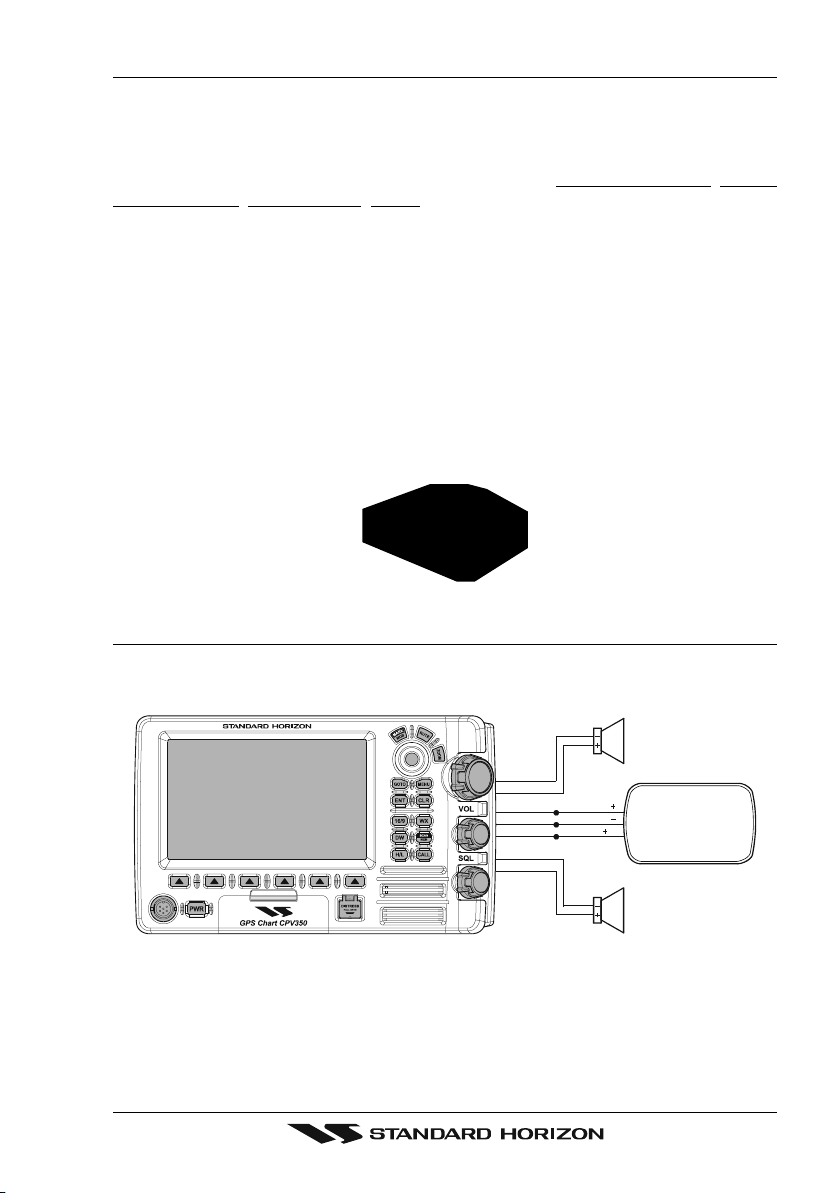
2.8 OPTIONAL VHF EXTERNAL SPEAKER
THE CPV350 has connections for an external VHF speaker for louder audio. Use Standard
Horizon MLS-300 or MLS-310 for best performance.
Shield
Red
Blue NMEA OUT
Green
NMEA OUT
NMEA IN
Gray
Shield
White
( )
( )
( )
PA Spe aker
EXTERNAL
NMEA DEVICE
External Speaker
Page 23CPV350
Page 24
3. C-MAP MAX OVERVIEW
3.0 INTRODUCTION
C-MAP MAX is a major evolution of the NT/NT+ product technology. Key points are:
New Data Features
· Tides and Currents (intuitive arrows show direction and strength)
· World Background Charts with terrestrial data
· Value Added Data (Pictures and Diagrams, Land Data)
· Enhanced Port Info
New Presentation Features
· Clear Info (sophisticated “Human Dictionary” to translate Nav-Aid abbreviations found
on paper charts)
· Dynamic Nav-Aids (an innovative and dynamic presentation mode)
· Flexi-Zoom (increased Under and Over Zoom between chart levels, resulting in optimal
scale display for any situation)
· Dynamic Elevation Data (optimized palettes for GPS chartplotters; includes new
NOAA palette)
· Perspective View (“Real World” perspective view of the chart, updated real-time during
navigation)
MAX and NT/NT
· When NT
from both charts (depending on the current position).
· When NT
+
C-CARD coexistence
+
data and MAX data cover different areas, the GPS chartplotter gets data
+
data and MAX data cover the same area, the GPS chartplotter gets data only
from MAX chart.
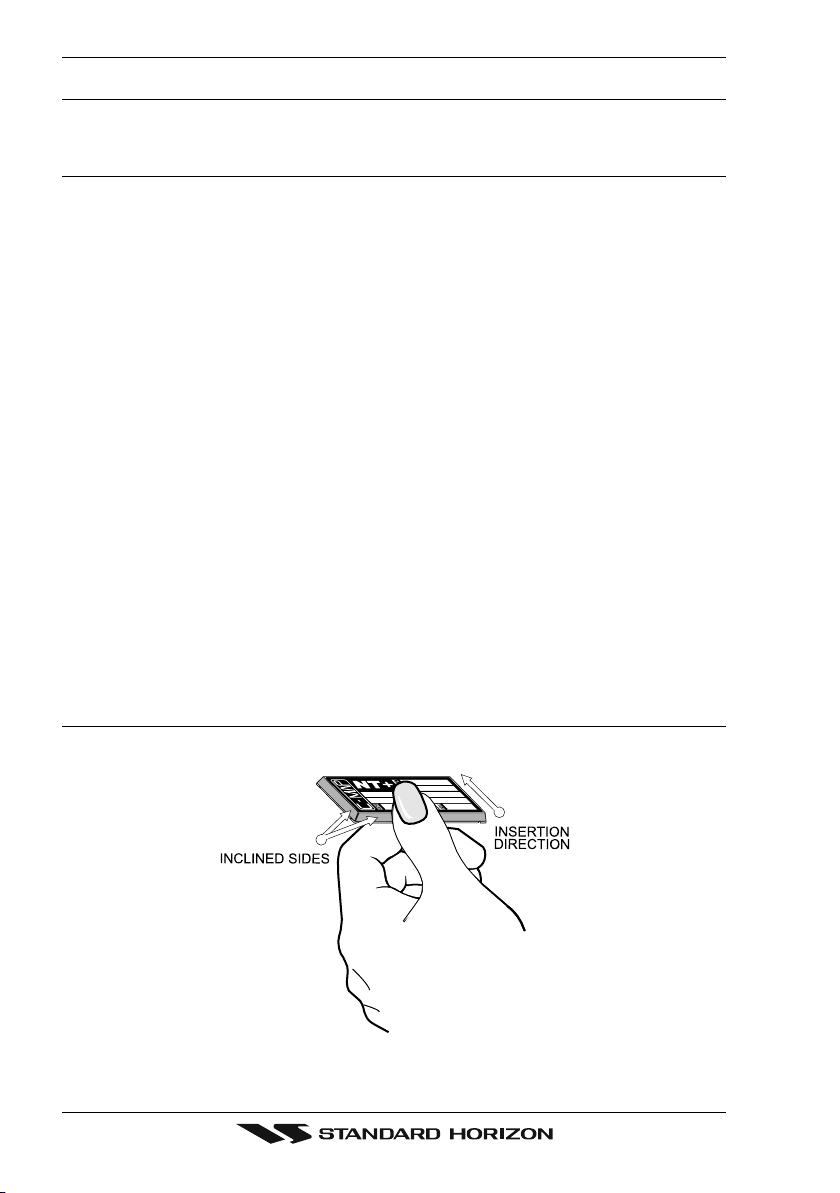
3.1 INSERTING THE C-CARD
Hold the C-CARD by the long inclined side so that you can see the C-MAP label.
Figure 3.1 - Inserting C-CARD
Page 24 CPV350
Page 25
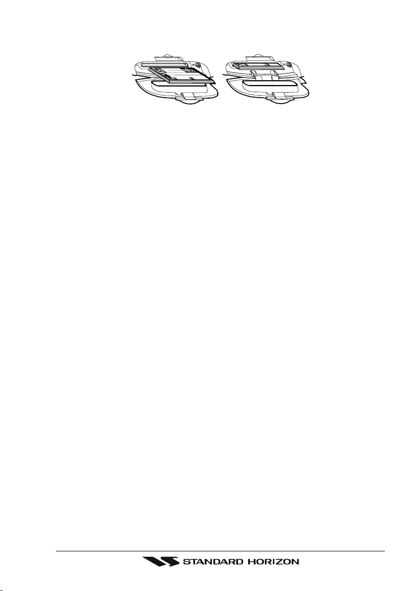
Open the door, gently push the C-CARD into the slot: push the C-CARD in as far as it will
go, then close the door.
Figure 3.1a - Inserting C-CARD (Details)
Page 25CPV350
Page 26
4. MAP FUNCTIONS
4.0 NEW MAX FUNCTIONS MENU
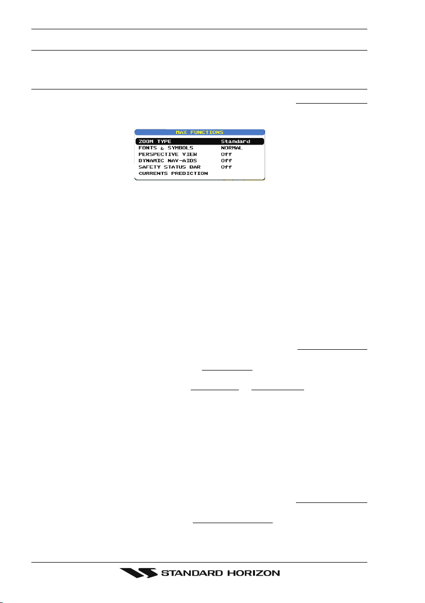
1. Press [MENU] two times. Move the ShuttlePoint knob to highlight MAX FUNCTIONS
and press [ENT] or move the ShuttlePoint knob to the right. The MAX Functions menu
appears on the screen:
Figure 4.0 - Map Functions Menu
The available Functions are described in the following.
4.0.0 Zoom Type
Allows more expansions or compression of the chart scale while zooming in or out. Zoom
Mode has two options; STANDARD (default) or FLEXI-ZOOM. When in FLEXI-ZOOM
mode, a short zoom push causes a change of chart, while a long zoom push causes a popup window to be displayed on a corner of the screen. The window shows the current Zoom
factor. By pressing [ZOOM] and moving the knob up/down the map is expanded or
compressed according to the zoom factor selected. The window is automatically closed if
[ZOOM] is not pressed for 2 seconds and the selected zoom factor will be used at the next
zoom in/out.
To activate this function follow the procedure:
1. Press [MENU] for two times. Move the ShuttlePoint knob to highlight
and press [ENT] or move the ShuttlePoint knob to the right.
2. Move the ShuttlePoint knob to highlight
ShuttlePoint knob to the right.
3. The menu now shows two selections,
4. Move the ShuttlePoint knob to select the selection and press [ENT].
5. Press [CLR] until the menu disappears or an easier method is to move the ShuttlePoint
knob to the left a few times.
ZOOM TYPE and press [ENT] or move the
STANDARD or FLEXI-ZOOM.
MAX FUNCTIONS
4.0.1 Fonts & Symbols
On MAX charts it is possible to set the size of all names and symbols drawn on the charts,
selecting between Normal size (the regular characters size) and Large size.
To activate this function follow the procedure:
1. Press [MENU] two times. Move the ShuttlePoint knob to highlight
and press [ENT] or move the ShuttlePoint knob to the right.
2. Move the ShuttlePoint knob to highlight
the ShuttlePoint knob to the right.
Page 26 CPV350
FONTS & SYMBOLS and press [ENT] or move
MAX FUNCTIONS
Page 27
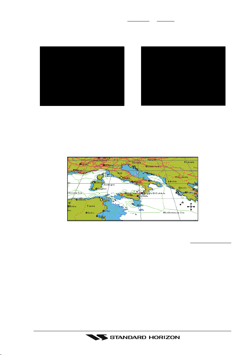
3. The menu now shows two selections, NORMAL or LARGE.
4. Move the ShuttlePoint knob to select the selection and press [ENT].
5. Press [CLR] until the menu disappears or an easier method is to move the ShuttlePoint
knob to the left a few times.
NORMAL size LARGE size
Figure 4.0.1 - Example of Normal size (on the left side) and Large side (on the right side) settings
4.0.2 Perspective View
Chart data may be projected in perspective mode during navigation. This function allows
setting the panoramic View of the chart. As the upper side of the map is more compressed
than the lower side, a wider map area is visible. The perspective view allows showing more
chart information immediately ahead and around the cursor.
Figure 4.0.2 - Perspective View
To activate this function follow the procedure:
1. Press [MENU] for two times. Move the ShuttlePoint knob to highlight
MAX FUNCTIONS
Page 27CPV350
Page 28

and press [ENT] or move the ShuttlePoint knob to the right.
2. Move the ShuttlePoint knob to highlight
the ShuttlePoint knob to the right.
3. The menu now shows two selections,
4. Move the ShuttlePoint knob to select the selection and press [ENT].
5. Press [CLR] until the menu disappears or an easier method is to move the ShuttlePoint
knob to the left until the chart page is shown.
PERSPECTIVE VIEW and press [ENT] or move
ON or OFF.
4.0.3 Dynamic Nav-Aids
This function enables the blinking of lights of the Nav-Aids. The blink period and color of
each Nav-Aid is read from the Nav-Aid attributes available on the data cartridge. When the
ship is inside the Nav-Aid nominal range, the light of the Nav-Aid will start blinking.
When Dynamic Nav-Aids option is set to On, when the flashing light is Off, or when fix
position is out of the sector, the light color is displayed by using a faint light color.
To activate this function follow the procedure:
1. Press [MENU] two times. Move the ShuttlePoint knob to highlight
and press [ENT] or move the ShuttlePoint knob to the right.
2. Move the ShuttlePoint knob to highlight
the ShuttlePoint knob to the right.
3. The menu now shows two selections,
4. Move the ShuttlePoint knob to select the selection and press [ENT].
5. Press [CLR] until the menu disappears or an easier method is to move the ShuttlePoint
knob to the left until the chart page is shown.
DYNAMIC NAV-AIDS and press [ENT] or move
ON or OFF.
MAX FUNCTIONS
4.0.4 Safety Status Bar (DSI - Data Safety Indicator)
When Safety Status Bar is On, a status bar with six boxes showing the status of certain
functions is displayed. Any warning or alarm condition is identified by the red color to
indicate possible risk.
To activate this function follow the procedure:
1. Press [MENU] two times. Move the ShuttlePoint knob to highlight
and press [ENT] or move the ShuttlePoint knob to the right.
2. Move the ShuttlePoint knob to highlight
move the ShuttlePoint knob to the right.
3. The menu now shows the following selections:
(Safety Status Bar is not shown),
alarm Icon is shown on the corner of the map screen as soon as any item controlled by
the DSI function returns an alarm condition. The Warning Icon remains displayed until
the alarm condition persists. Placing the cursor over this Icon, a quick help message is
shown next to the Icon, allowing to show the Safety Status Bar. In this case - when the
Safety Status Bar is opened via Warning alarm Icon - it is allowed to obtain information
about each “active” Safety Status box (the red ones): it is possible to select them by
ShuttlePoint knob movement left/right, and a list of active alarms is shown underneath
the selected box. By pressing [CLR], the Safety Status Bar is removed from the screen)
4. Move the ShuttlePoint knob to select the selection and press [ENT].
5. Press [CLR] until the menu disappears or an easier method is to press the ShuttlePoint
knob to the left a few times.
Page 28 CPV350
SAFETY STATUS BAR and press [ENT] or
ON (Safety Status Bar is shown), OFF
ICON (Safety Status Bar is not shown, but a Warning
MAX FUNCTIONS
Page 29
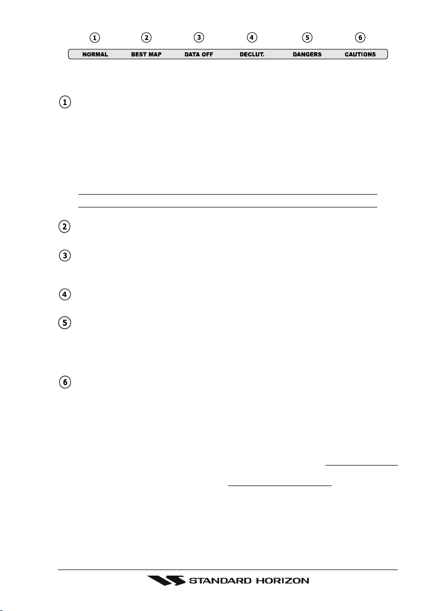
Figure 4.0.4 - Safety Status Bar
The boxes are defined as follows:
Zoom
♦ Normal: when the chart is displayed at normal scale.
♦ U. Zoom: red when the chart is under-zoomed out more than twice normal
scale, gray otherwise.
♦ O. Zoom: red when the chart is over-zoomed in more than twice normal scale,
gray otherwise.
♦ Chart Lock: red when the chart is zoomed in more than twice normal scale,
gray otherwise.
NOTE
U. Zoom, O. Zoom and chart lock are used with Flexi-zoom selected.
Best Scale
Red when a more detailed chart is available under the cursor position.
Data Off
Red when at least one of the following objects or layers is turned off (by the user):
Depths/soundings; Wrecks/obstructions; Tracks/routes; Attention Areas; Nav-Aids.
Declutter
Displays red when clearing overlapping objects.
Dangers
Red when “Guardian Technology” detects one of the following objects: Land, Intertidal, Depth Area, Rocks, Obstructions, Shoreline Constructions, Fishing Facility,
Wrecks, Dragged area, Diffusion area, Mooring facilities, Pingos and Production installations.
Caution
Red when “Guardian Technology” detects cautionary or restricted area.
4.0.5 Currents Prediction
When enabled shows the variation of the tidal arrows on the selected area at any given time.
To activate this function follow the procedure:
1. Press [MENU] two times. Move the ShuttlePoint knob to highlight
and press [ENT] or move the ShuttlePoint knob to the right.
2. Move the ShuttlePoint knob to highlight
CURRENTS PREDICTION and press [ENT]
or move the ShuttlePoint knob to the right.
3. A window is shown on the low-left side of the chart. Press [S
time manually, and [I
NCR. TIME]/[DECR. TIME] to decrease/increase time; press [EXIT] to
exit.
MAX FUNCTIONS
ET TIME] to set the date and
Page 29CPV350
Page 30
5. DATA FEATURES
This chapter contains the new features related to the MAX map data files (i.e.: cartography
and related data).
5.0 PICTURES & DIAGRAMS
Using C-Map MAX data cards allows you to show pictures or diagrams on the chart plotter
display. These Pictures are typically used to facilitate the identification of cartographic
objects or places around the map: they can be the landscape layout nearby a harbor, the
shape of a bridge or of a buoy etc.
On some objects, such as bridges, the image associated can represent the Diagram
representing the shape of the objects and the various characteristics (length, height, type
of bridge etc.).
Figure 5.0 - Pictures and Diagrams
The pictures or diagrams can be a MULTIMEDIA OBJECT or they can be associated to a
generic cartographic object, like a port marina.
Page 30 CPV350
Page 31

5.0.0 How to show the pictures or diagrams of a Multimedia Object
They are shown on the chart page with the camera icon
Move the cursor over the camera icon. You will get the quick info on the object and there
will be the camera icon on the top bar of the window:
Figure 5.0.0a - Example of Quick Info on MULTIMEDIA object
Press [IMAGE] for 1 second to display the image on the screen or press [EXPAND] to open
the Full info on the object:
Figure 5.0.0b - Example of Full Info on MULTIMEDIA object
On the Full Info, there will be the small camera icon on a corner of the square containing
the object icon.
To see the picture press [MENU] when the object with a picture is highlighted.
When the picture is shown, it is possible to fit it to screen by pressing [ENT].
When the picture is shown, it is possible to change the contrast by pressing [ZOOM] and
moving the knob.
When the picture is shown, it is possible to display the next picture associated, if any, by
pressing the ShuttlePoint knob left or right.
5.1 ENHANCED PORT INFO
MAX charts include additional port services that were not present before. Additional
attributes of Port Areas and Port Marinas have been included (Location, Country, Region,
State, Harbor master telephone number etc.).
Page 31CPV350
Page 32

6. CONTROLS AND INDICATORS
LEGEND
[MENU] If you see brackets around a bold and capital letter word this refers to a key press.
[CHART] If you see brackets around a bold and small capital letter word this refers to a Soft Key
press. When a word(s) is bold capital letters and underlined, this refers to a menu selection item.
6.0 CONTROLS AND CONNECTIONS
The GPS Chart plotter, VHF radio, PA and optional FF520 fish finder are controlled using the
keys located on the front panel. These labeled keys are dedicated to specific functions. As you
press a key, a single audio beep confirms the key action; every time a key press is not valid,
three rapid beeps sound to indicate that the key action is not valid. There is also a ShuttlePoint
knob to move the cursor across the screen.
The ZOOM key
Pressing this key enables or disables the chart plotter zoom function or VHF channel
selection.
Press the [ZOOM] key and a zoom icon will appear on the top left of the display as shown
below. When this icon is shown the zoom function is enabled and the channel selector knob
is used to change the zoom levels. When the icon is not shown turning the knob changes
the VHF channels.
To zoom in rotate the channel selector knob Clockwise (up) or to zoom out rotate the
channel knob counter clockwise (down). When finished zooming press the [ZOOM] key.
Rotating the channel knob.
NOTE
The GPS chartplotter contains a Worldwide background that allows you to zoom into 2 NM. For
more detail, a C-MAP NT+/MAX C-CARD must be purchased and installed.
The ShuttlePoint knob
The ShuttlePoint knob moves the cursor about on the display screen, quickly and
accurately. It also scrolls the desired option in the menu page(s). It allows to exit from Home
mode to Cursor mode. when the setup menu is selected, moving the knob to the right selects
the desired option, as [ENT], moving it to the left exits from menu, as [CLR]. For a detailed
explanation of Cursor VS Home mode refer to section 6.1.1.
The ENT key
Press [ENT] to select the desired option or to confirm selection.
The CLR key
Press [CLR] to set Home mode. Also press [CLR] to exit from menu or data windows or to
leave a menu without making changes, to abort selected function or to step backward from
a selection made in the menu.
The MENU key
Pressing [MENU] one time selects the Main Menu. While the Main Menu is shown, move
the ShuttlePoint knob up or down or left or right to highlight a selection. Press the [ENTER]
to choose the selection.
Pressing [MENU] two times selects the Setup Menu.
Page 32 CPV350
Page 33

Press and hold the [MENU] key for about 3 seconds allows the fields in the data windows
to be customized on the Chart, Navigation, Highway, GPS Status or NMEA display pages.
The GOTO key
This key is very useful when you desire to start navigating (goto) to a destination point. When
pressed shows a popup window that allows you to select to start navigating to the position
of the cursor, Mark or Route.
The MARK/MOB key
Pressing [MARK/MOB] and immediately releasing places Mark under the ship's position
when in Home Mode (in Cursor Mode under the cursor).
Press and holding [MARK/MOB] for about 3 seconds automatically places a MOB on the
Chart page and all navigation is towards the position of the MOB Mark.
The RTE key
When pressed places a Waypoint. Succeeding presses place more Waypoints to form a
Route.
The PWR key and Lamp/Contrast
Press and hold [PWR] to turn the GPS chartplotter On or Off. When the CPV350 is on, press
the [PWR] key to shown the contrast and Lamp popup window. Move the ShuttlePoint knob
left/right to adjust the backlight and up/down to adjust contrast.
The Soft Keys
The 6 keys in the bottom part of the front panel (hereinafter named Soft Keys) have different
functions associated depending on the page selected: their labels are shown on the screen
immediately above the keys (the user can customize the function associated).
These keys allow quick selection to the many pages the GPS chartplotter has. These keys can
be customized to your preference, however from the factory the keys are preprogrammed with
the following pages. From left to right CHART, NAV, HIGHWAY, CELESTIAL, NMEA
DISPLAY, LIST. Press any of the keys and you will see popup windows above the keys. To
goto a specific page press the key with the desired popup window. The popup windows will
automatically disappear if a key is not pressed or can be removed by pressing [CLR].
6.1 GETTING STARTED
The Getting Started section will take you through the frequently used operations and assist
you to customize the look of the GPS chartplotter.
Legend:
[MENU] If you see brackets around a bold and capital letter word this refers to a key press.
HART] If you see brackets around a bold and small capital letter word this refers to a Soft Key press.
[C
GENERAL SETUP When a word(s) is bold capital letters and underlined, this refers to a menu selection item.
6.1.0 Power On, Off and ShuttlePoint knob operation
1. Press and hold [PWR] until the display shows the start-up page. To turn off, press and
hold [PWR] until the display turns off.
2. When the power is first turned on two pages (the start-up page, see the following picture,
and the Caution page) are briefly shown before the GPS Status page.
Page 33CPV350
Page 34

Figure 6.1.0 - Start-Up page
3. When the GPS chartplotter is first turned on it will take some time for the GPS to acquire
a fix of your position. Look closely at the GPS Status page and you will see satellites and
relative signal strengths. After a fixed is received the GPS chartplotter will automatically
switch to the Chart page with a ships icon centered on the screen.
1
2
Ships Icon
Cursor
1
Figure 6.1.0a - GPS Status and Chart pages
2
4. On the Chart page the ShuttlePoint knob is used to pan around the chart. Move the ShuttlePoint
knob to the left and you will notice a cross hair
appears, this is called the cursor.
5. When you move the ShuttlePoint knob you will notice DST and BRG values in the Data
window change. This shows the Distance and Bearing from the GPS Fix of your vessel
to the position of the Cursor.
6. If the cursor is moved to the edge of the screen the GPS chartplotter will automatically
pan in the desired direction.
6.1.1 Cursor Vs. Home Mode
Cursor Mode
When the
In Cursor mode the position of the vessel will not stay in the center of the page and will move
right off the edge of the screen (as your boat moves) Cursor mode allows you to pan around
and look at areas on the map. In this mode your can also measure distance and bearings
from your current position.
cursor is shown on the Chart page, this is called Cursor mode.
NOTE
To change from Cursor mode to Home mode press [CLR].
Home mode
When the
Page 34 CPV350
ships icon is only shown on the Chart page (cursor is not shown) you are in
Page 35

Home mode. Now as the ship moves through the water the vessels position will be kept in
the center of the display.
6.1.2 Cursor and Menu selection speed
The GPS chartplotter allows you to control the speed the Cursor moves when the
ShuttlePoint knob is pressed. To change the speed:
Figure 6.1.2 - Cursor Speed menu
1. Press [MENU] two times. Move the ShuttlePoint knob to highlight GENERAL SETUP
and press [ENT] or move the ShuttlePoint knob to the right.
2. Move the ShuttlePoint knob to highlight
ShuttlePoint knob to the right.
3. The menu now shows two selections, CHART and MENU which allows the Cursor
Speed to be selected to High, Medium or Low on Chart page or within the menus.
4. With
CHART or MENU selected, press [ENT] or move the ShuttlePoint knob to the right.
Move the ShuttlePoint knob to the desired setting and press [ENT] or move the
ShuttlePoint knob to the right.
5. Press [CLR] until the menu disappears or an easier method is to press the ShuttlePoint
knob to the left a few times.
6. Move the cursor on the Chart page and see if the speed is to your liking.
CURSOR SPEED and press [ENT] or move the
6.1.3 Changing the Ships Icon
The cursor may be changed to any of the following:
Figure 6.1.3 - Ship icons
1. Press [MENU] two times. Move the ShuttlePoint knob to highlight GENERAL SETUP
and press [ENT] or move the ShuttlePoint knob to the right.
2. Move the ShuttlePoint knob to highlight
ShuttlePoint knob to the right to show the popup window with ship icons.
3. Move the ShuttlePoint knob to select the desired icon and press [ENT] or move the
ShuttlePoint knob to the right to select a new icon.
4. Press [CLR] or move the ShuttlePoint knob to the left to exit the menu and show the
Chart page.
SHIP ICON and press [ENT] or move the
Page 35CPV350
Page 36

6.1.4 Changing the backlight and contrast
With the GPS chartplotter turned On, briefly press [PWR] to show the light and contrast
popup window. Move the ShuttlePoint knob to the left or right to adjust the LCD backlight
intensity or up or down to change the LCD contrast. Press [ENT] to set.
Figure 6.1.4 - Backlight and Contrast adjustment
6.1.5 Selecting North Up or Course Up
You may select the Chart page between NORTH UP and COURSE UP which the top of the
Chart page oriented so it will always show the area ahead of the direction your vessel is
traveling.
Figure 6.1.5 - Course Up/North Up menu
1. Press [MENU] two times. Move the ShuttlePoint knob to highlight GENERAL SETUP
and press [ENT] or move the ShuttlePoint knob to the right.
2. Move the ShuttlePoint knob to highlight
move the ShuttlePoint knob to the right.
3. Another popup window will be shown with
ShuttlePoint knob to the desired selection and press [ENT] or move the ShuttlePoint
knob to the right.
4. Press [CLR] or move the ShuttlePoint knob to the left to exit the menu and show the
Chart page.
When the GPS chartplotter is in COURSE UP mode a small arrow icon will be shown on the Chart
page indicating the direction of North.
COURSE UP/NORTH UP and press [ENT] or
NORTH UP and COURSE UP, move the
NOTE
Page 36 CPV350
Page 37

6.2 ADJUSTING THE TIME
The time information supplied by the GPS satellites is in Universal Time Coordinates (UTC
or Greenwich England Mean Time). To change the GPS chartplotter to read the correct
time, first you must figure out the offset and if it is daylight savings time. For example on the
West coast of the United States or Pacific Standard Time the offset needed would be –08:00
or –07:00 for daylight savings time, Eastern Standard Time –05:00 or –04:00 for daylight
savings time.
Figure 6.2 - Adjusting Time
NOTE
This map shows offset for standard time. For daylight saving time, subtract one hour from the offset time.
Figure 6.2a - Time Setup menu
1. Press [MENU] two times. Move the ShuttlePoint knob to highlight GENERAL SETUP
and press [ENT] or move the ShuttlePoint knob to the right.
2. Move the ShuttlePoint knob to highlight
TIME SETUP and press [ENT] or move the
ShuttlePoint knob to the right.
3. Move the ShuttlePoint knob to highlight
GPS TIME OFFSET and press [ENT] or move
the ShuttlePoint knob to the right.
4. Move the ShuttlePoint knob down to select +00:00, press [ENT] and move the
ShuttlePoint knob to the right to edit the number.
5. Look at the table and find the offset for your area. You will need to enter this offset to
make the GPS chartplotter shows the correct time.
Page 37CPV350
Page 38

6. Move the ShuttlePoint knob to the “+”. Move the ShuttlePoint knob up or down to change
to the desired offset.
7. Next move the ShuttlePoint knob to the right to select Hours and move the ShuttlePoint
knob up or down to change the hour.
8. Repeat this method to change the minutes, if necessary.
9. Once you have the correct GPS time offset, press [ENT] to set.
6.3 SELECTING LORAN TD OR OTHER COORDINATE SYSTEM
The GPS Fix coordinates can be changed to show Latitude/Longitude, Loran TD’s or UTM.
Below is the window that will appear when customizing the Coordinate System.
Figure 6.3 - Coordinate System menu
1. Press [MENU] two times. Move the ShuttlePoint knob to highlight ADVANCED SETUP
and press [ENT] or move the ShuttlePoint knob to the right.
2. Move the ShuttlePoint knob to highlight
ShuttlePoint knob to the right.
3. Move the ShuttlePoint knob to highlight
move the ShuttlePoint knob to the right.
4. Move the ShuttlePoint knob to highlight the desired coordinate type and press [ENT] or
move the ShuttlePoint knob to the right.
5. Press [CLR] or move the ShuttlePoint knob to the left until the Chart page is shown.
If the TD is selected, you should set the Chain, Pair, ASF1, ASF2 and Alter. If the TD numbers are
not correct the Pair letters may be backwards. Reversing the two letters usually solves this issue.
Example Y/Z change to Z/Y.
NAVIGATE and press [ENT] or move the
COORDINATE SYSTEM and press [ENT] or
NOTE
Page 38 CPV350
Page 39

6.4 CHANGING THE CHART COLOR
The GPS chartplotter has preprogrammed settings allowing you to customize the look of the
Chart page. The default is “Sunlight” however there are other settings: Normal, Classic,
NOAA and Night. Night is very useful during evening hours so not to impair night vision.
Figure 6.4 - Display Color menu
1. Press [MENU] two times. Move the ShuttlePoint knob to highlight GENERAL SETUP
and press [ENT] or move the ShuttlePoint knob to the right.
2. Move the ShuttlePoint knob to highlight
DISPLAY COLOR and press [ENT] or move the
ShuttlePoint knob to the right.
3. A popup window will be shown with Normal, Classic, NOAA, Night and Sunlight. Move
the ShuttlePoint knob to the desired selection and press [ENT] or move the ShuttlePoint
knob to the right.
4. Press [CLR] or move the ShuttlePoint knob to the left to exit the menu and show the
Chart page.
6.5 SELECTING PAGES USING SOFT KEYS
The Soft Keys located under the LCD are used to select the pages quickly without the need
to go into the menu. The default pages are CHART, NAV, HIGHWAY, CELESTIAL, NMEA
DISPLAY and LIST.
When one of the Soft Keys is pressed popup windows above each Soft Key are shown with
the key description. Press the Soft Key with the desired page description and the GPS
chartplotter will change to that page.
CHART
NAVIGATION
HIGHWAY
CELESTIAL
GPS STATUS
NMEA DISPLAY
Kts
3.1
M
353°
M
015°
Figure 6.5 - Screen display pages
FISH FINDER full screen window
Shown only with optional F 520 connectedF
Page 39CPV350
Page 40

6.6 CUSTOMIZING THE SOFT KEYS
The Soft Keys can be individually customized from the default pages (discussed above) to
the following: CHART, CHART/COMPASS, CHART/HIGHWAY, NAVIGATION, HIGHWAY, CELESTIAL, GPS STATUS, DSC LOG*, DSC DIRECTORY*, NMEA DISPLAY,
NMEA DATA, DEPTH TREND, WIND SPEED TREND, TEMP TREND, SOG TREND,
MARKS/WAYPOINTS and USER C-CARD.
When the Optional FF520 50/200kHz BLACK BOX FISH FINDER is connected, any Soft
Key can be customized to show 50 or 200kHz full page, 50 or 200kHz Chart/Fish split screen
and zoom screens.
Figure 6.6 - Window options of the selected Soft Key
1. To change, momentarily press any of the Soft Keys, then press and hold the Soft Key
you want to customize.
2. A popup window will be shown with the above settings.
3. Move the ShuttlePoint knob up or down to select the desired page.
4. Press [ENT] or move the ShuttlePoint knob to the right to save the page to the selected
Soft Key.
6.7 OTHER SETTINGS IN GENERAL SETUP MENU
You will notice the GENERAL SETUP menu has other selections that allow you to customize:
TIME SETUP Selects a submenu to allow the time setup. It is possible to set the GPS Time Offset,
DATE FORMAT Allows choosing date format MM-DD-YY or DD-MM-YY.
COURSE UP/NORTH UP Selections are:
KEYPAD BEEP Allows the beep produced when a key is pressed to be turned on or off.
UNITS OF MEASURE Units of Measure can be selected for Distance, Speed, Depth, Altitude and Temperature.
NAV AIDS PRESENTATION Allows the Nav Aids presentation to drawn using NOAA symbology when US is selected
DISPLAY COLOR Changes the background colors of the chart page to enhance the visibility of the screen
Page 40 CPV350
choosing the UTC or Local Time display, and the Time Format, switching 12 or 24 hours
time format.
North Up : The Top of the page is fixed to North
Course Up : The top of the page is orientated to the direction the vessel is heading.
or International symbols will be used when International is selected. When selected these
functions affects how the icons for Lights, Signals, Buoys and beacons are displayed.
depending on the surrounding light conditions. Normal is recommended when the GPS
chartplotter is not exposed to the direct sunlight. When this mode is set the maps are
displayed in order to use colors as similar as possible to ones used in the original paper
charts. Classic uses vivid chart colors presentation. NOAA allows setting NOAA paper
chart colors presentation. Night is recommended when the environment is dark in order
to reduce the glare of the display. The GPS chartplotter displays maps and screen in
darker colors. Sunlight (default) is designed to enhance the visibility of the screen when
the GPS chartplotter is exposed to sunlight. The maps are much brighter than in the other
Page 41

modes and the depth areas are filled with the white color so different depth areas not
SHIP ICON Allows selection of one of 5 choices of ship icons that represent you vessels position
CURSOR SPEED Selects the preferred speed among Low, Medium and High for the cursor in the Chart page
MEASURE DISTANCE When this function is turned on allows a distance to be measured between two points
WINDOWS SETUP This menu selection allows the data windows to be customized on the Chart and
LANGUAGE Allows changing the language for menus and data screens.
AUTO INFO By default when the cursor is moved over a buoy, Mark or other item a popup window will
CURSOR WINDOW By default when the cursor is moved a window is shown with the Lat/Lon Distance and
CURSOR POSITION The position of the cursor (vessels location) can be customized so it centered in the middle
COG TIME LINE Is a line projected from the vessel icon which indicates the distance your vessel will travel
easily distinguishable.
shown on the chart page.
and within the menu.
using the ShuttlePoint knob and [ENTER] key
Navigation pages.
show information of the item. This menu item allows the window to be turned on or off.
bearing from the vessels location to the cursor. This selection allows the window to be
turned off.
or centered on the bottom of the chart page. The default is “Bottom”.
at the current speed. Selections are 2, 10, 30 minutes, 1, 2 hours and infinite.
6.8 INFORMATION PAGE
From Setup Menu page it is possible to select an Information page containing Software,
Chart and Optional devices information.
XXXXXX Version YY.YY
1
Software System Information
1
Cartography Information
2
Storage Capacity
3
Figure 6.8 - Information page
M-NA-M632.00 LOS ANGELES and SAN PEDRO BAYS
2
3
1. Press [MENU] two times. Move the ShuttlePoint knob to highlight About... and press
[ENT] or move the ShuttlePoint knob to the right.
2. The Information page appears on the screen (see the previous Figure).
3. Press [CLR] or move the ShuttlePoint knob to the left to exit and show the Chart page.
Page 41CPV350
Page 42

7. USING FIND SERVICES & MORE FUNCTION
With a C-MAP NT+/MAX C-CARD installed the GPS chartplotter allows you to search for
a Port Service, Port, Tide Stations, Wrecks, Obstructions, POIs, Lakes, User Points, or
GPS Coordinates.
7.0 PORT SERVICES
1. Press [MENU]. Move the ShuttlePoint knob to highlight FIND SERVICES and press
[ENT].
2. Move the ShuttlePoint knob to highlight
ShuttlePoint knob to the right.
3. A popup window will be shown with the Port Services.
4. Move the ShuttlePoint knob to highlight the desired Service and press [ENT].
5. Another popup window will show the name, distance and position of the Services closest
to your location.
6. Using the ShuttlePoint knob, highlight the desired Service and press [ENT] which will
show the name and phone number of the Service.
7. Press [CLR] which will show the available Services at the location.
8. Press [CLR] to show the actual position of the Services.
PORT SERVICE and press [ENT] or move the
Figure 7.0 - Port Services
7.1 OTHER AVAILABLE SEARCHES
PORT BY NAME Searches and shows on the Chart page the list of all ports stored on the C-CARD in alphabetic
PORT BY DISTANCE Searches and shows the list of all ports stored on the C-CARD in distance order
TIDE STATIONS Searches for the closest Tide Station and shows the information of the tide station
WRECKS Searches and shows on the Chart page for the closest Wrecks
OBSTRUCTIONS Searches and shows on the Chart page for the closest Obstructions
USER POINTS Searches and shows on the Chart page for the closest User Points (Marks or Waypoints)
COORDINATES Searches and shows on the Chart page for GPS Coordinates
POIs Searches and shows information on the selected Point Of Interest
LAKES Searches and shows information on the selected Lake
INFORMATION Searches and shows information on the selected point
Page 42 CPV350
order
Page 43

7.2 INFO ON LAKES (WITH OPTIONAL C-MAP LAKES CARTOGRAPHY)
7.2.0 Quick Info On Lakes
Upon viewing the chart of a lake, you will click on to query the available information
immediately displayed with many details. For example, see the following picture:
Lakes Info icon
Figure 7.2.0 - Example of Lakes info
When the cursor is placed over the icon, the icons of the available services are shown:
Figure 7.2.0a - Quick Info: available services
If you press [ENT] all available information about the cartographic point under the cursor
will be shown. See the next paragraph.
7.2.1 Full Info On Lakes
The following is an example of Full Info on Lakes:
Figure 7.2.1 - Example of Full Info page
Page 43CPV350
Page 44

To see the “Fishing” object press [MENU] (when the “Fishing” object is highlighted). On the
screen appears:
Figure 7.2.1a - Example of picture associated to the Fishing object
Page 44 CPV350
Page 45

8. CREATING MARKS
MARK
Can be a stand alone position or be linked to a Route. A Mark is placed on the Chart page
using [MARK/MOB] or by entering in information in the
selection.
WAYPOINTS
Always linked to a Route. Are placed on the Chart page using [RTE].
NOTE
The difference between a Mark and a Waypoint is
a. When a Route is created using WAYPOINTS and the ROUTE is deleted the WAYPOINTs are
also deleted.
b. If a Route is created using MARKS and the ROUTE is deleted the MARKs remain.
8.0 CREATING A NEW MARK USING THE CHART PAGE
1. Move the ShuttlePoint knob to the desired or approx. Lat/Lon and press [MARK/MOB].
2. You will notice a Mark is placed under the location of the Cursor and a popup window
is shown with the exact Lat/Lon of the Mark.
3. If the position is incorrect press [E
name, icon type and color of the icon.
DIT] that will allow you to change the position, Mark
Mark/Wpt List NEW MARK
Mark placed under Cursor
1
Lat/Lon of Mark, DST/BRG
2
from vessel location
Press Soft Key to show the
Marks/Waypoint List, to edit,
3
to move or to delete Mark
4
Vessel location
1
4
2
3
Figure 8.0 - Mark creation
8.1 EDITING A MARK
If a Mark has previously been created and you wish to Edit it, move Cursor over the top of the Mark.
Figure 8.1 - Mark editing
1. After a Mark is created, press [EDIT] to show the edit popup window.
2. Use the ShuttlePoint knob to change to the desired Mark Icon, when finished press
[ENT].
3. Move the ShuttlePoint knob to the right to select the Mark Name. Press [ENT] an the
Page 45CPV350
Page 46

first digit in the name will be highlighted.
4. Move the ShuttlePoint knob up or down to select the first character.
5. Move the ShuttlePoint knob to the right to select the next character.
6. Repeat steps 4 and 5 until the Mark name is shown. Press [ENT].
7. Move the ShuttlePoint knob to the right and press [ENT] to change the Mark Icon’s
Color.
8. Move the ShuttlePoint knob to up/down, left/right to select the Mark Icon’s Color. When
finished press [ENT].
9. Move the ShuttlePoint knob to the right to select the Lat/Lon and press [ENT].
10. Move the ShuttlePoint knob up or down to select the first character.
11. Move the ShuttlePoint knob to the right to select the next character.
12. Repeat steps 10 and 11 until the desired position is shown. Press [ENT] and [CLR] to
store the Mark.
8.1.0 Deleting a Mark or Waypoint
Move the cursor over the Mark or Waypoint to delete. Press [DELETE]. A Warning popup
window will be shown. Select
YES and press [ENT].
8.1.1 Moving a Mark or Waypoint
Place the cursor over the Mark or Waypoint which you want to move. Press [MOVE]. Use
the ShuttlePoint knob to move the cursor. A dotted line, connecting the previous Waypoint
position to the new position, is shown:
Figure 8.1.1 - Moving Mark or Waypoint (I)
Press [ENT] ([CLR] to abort the move), the Waypoint appears in the new position.
Figure 8.1.1a - Moving Mark or Waypoint (II)
Page 46 CPV350
Page 47

8.2 MARKS/WAYPOINTS LIST
The Marks/Wpt List shows all the Marks and Waypoints that have been stored into the GPS
chartplotter. This page also allows you to:
ICON Allows sorting by icon type
FIND Searches through the Marks or Waypoints to find a point by name using the ShuttlePoint knob
LOCATE Shows the position of a Mark or Waypoint on the Chart page
EDIT Allows you to edit a previous stored Mark or Waypoint
SORT Sort the name of the Mark or Waypoint in ascending or descending order
NEW MARK Allows entering in Marks, editing icon type and position
MODE This selection controls how the Marks or Waypoints are shown on the Chart page. Selections are:
DELETE Delete the selected point
DEL ALL Delete all stored points
SEND Sends the stored points to a external device (PC) capable of listening to NMEA WPL sentence.
RECEIVE Receive the points from an external device (PC) that is capable of sending NMEA WPL
The SEND and RECEIVE functions are usually used by navigation programs running on a Personal
Computer example Nobeltech.
a. SHOW - icon and name are shown
b. ICON - only icon (no name) is shown
c. HIDE - Mark or Waypoint is hidden
d. SHOW ALL - All Marks or Waypoints are shown
e. ICON ALL - All Icons are shown without name
f. HIDE ALL - All Marks or Waypoints are hidden
sentence.
NOTE
Figure 8.2 - Marks/Waypoints List
8.3 CREATING A NEW MARK WITH THE MARKS/WAYPOINTS LIST
NOTE
This function is very useful if you have a list of Marks that you want to enter into the GPS chartplotter.
1. Press [MENU]. Move the ShuttlePoint knob to highlight USER POINTS and press
[ENT].
2. Move the ShuttlePoint knob to highlight
3. The Marks/Wpt List page will be shown (see previous picture).
4. To create a New Mark, move the ShuttlePoint knob to the right to highlight
and press [ENT].
5. Press [ENT] to change to show the Icon popup window.
6. Move the ShuttlePoint knob to highlight the desired Icon and press [ENT].
7. Move the ShuttlePoint knob to the right to select the Mark name. Press [ENT] and the
Marks/Wpt and press [ENT].
NEW MARK
Page 47CPV350
Page 48

first digit in the name will be highlighted.
8. Move the ShuttlePoint knob up or down to select the first character.
9. Move the ShuttlePoint knob to the right to select the next character.
10. Repeat steps 8 and 9 until the Mark name is shown. Press [ENT].
11. Move the ShuttlePoint knob to the right to select the Lat/Lon and press [ENT].
12. Move the ShuttlePoint knob up or down to select the first character.
13. Move the ShuttlePoint knob to the right to select the next character.
14. Repeat steps 12 and 13 until the desired position is shown. Press [ENT] and [CLR], a
WARNING “Save the new Mark?” popup window will be shown, move the ShuttlePoint
knob to the right or left to select
YES or NO and press [ENT].
8.4 GOTO CURSOR
The GPS chartplotter allows you to quickly start navigating to the Cursor, Mark or Route.
GOTO CURSOR
1. Move the ShuttlePoint knob to the exact position you want to navigate to.
2. Press [GOTO] and a GOTO popup window will be shown
Figure 8.4 - GO TO menu
3. Move the ShuttlePoint knob to highlight CURSOR and press [ENT].
4. The GPS chartplotter is now navigating from your current position to the location
selected at step 1.
Figure 8.4a - Navigating to Cursor Example
5. Now the GPS chartplotter shows a navigation line between the vessels location and the
destination point. A popup window shows the Distance (DST) and Bearing (BRG) from
the vessels location to the destination point.
6. The GPS chartplotter is in Cursor mode, to switch to Home mode press [CLR] to so the
vessel stay in the center of the page.
7. Two Soft Keys are also shown that allow you to quickly switch to the HIGHWAY page
or to stop navigation.
8. To STOP Navigation, press [GOTO] and the WARNING page is shown. Select
STOP
and press [ENT].
Page 48 CPV350
Page 49

8.5 GOTO MARK
1. Move the ShuttlePoint knob to an open position (no buoy, warning etc. under the cursor)
on the Chart page.
2. Press [GOTO] to show the GOTO popup window.
3. Move the ShuttlePoint knob to highlight
List.
4. Move the ShuttlePoint to the highlight the desired Mark or Waypoint and press [GOTO].
5. You will notice a circle is drawn around the Icon Symbol. This means the GPS
chartplotter is now navigating to the point.
6. Press [CLR] to switch to the Chart page or Highway page to start navigating to the point.
MARK and press [ENT] to show the Marks/Wpt
Page 49CPV350
Page 50

9. MAN OVER BOARD (MOB) FUNCTION
During navigation, the “MOB” feature provides a one-touch method of storing a location
(such as a point were a crew member fell overboard). In this mode, the GPS chartplotter
places a MOB point on the Chart page and all the navigation data shown is related to
navigating back to this point, allowing you to retrace your path to the MOB point efficiently.
1. On the Chart page, press [MARK/MOB] to start navigating back to the point.
2. You will notice a MOB Mark will be laid on the Chart page and all navigation is referring
back to this point.
3. If the cursor is moved over the MOB Icon, popup windows over Soft Keys will be shown
allowing quick access to the Navigation or Highway pages.
9.0 DELETING A MOB POINT
1. Move the ShuttlePoint knob until the cursor is over the top of the MOB icon.
2. Press [D
3. Move the ShuttlePoint knob to highlight
ELETE], a popup window will be shown to confirm deleting the MOB point.
YES and press [ENTER].
Page 50 CPV350
Page 51

10. ROUTES
The GPS chartplotter has the capability to store 20 Routes with a maximum of 50 Waypoints
each.
A Route can consist of Waypoints or Marks. The difference is when a Route is made using
Waypoints and the Route is deleted the Waypoints are also deleted. However if a Route is
made of Marks and the Route is deleted the Marks stay in memory.
10.0 CREATING A ROUTE USING WAYPOINTS
1. On the Chart page move the ShuttlePoint knob to the Lat/Lon of the starting Waypoint
in the Route.
2. Press [RTE], you will notice the Starting Waypoint
3. Move the ShuttlePoint knob to the second Lat/Lon of the next leg
4. Press [RTE]. You will notice another Waypoint is shown under the cursor and a line joins
the starting Waypoint to the Second Waypoint.
will be placed under the cursor.
in the Route.
Figure 10.0 - Creating a Route using Waypoints
5. Repeat steps 3 and 4 until all Waypoints are entered into the Route.
NOTE
At this point the Route is saved as ROUTE01. If you would like to save the Route under a specific
name follow the remaining steps.
6. To name the Route press [MENU]. Move the ShuttlePoint knob to highlight USER
POINTS and press [ENT].
7. Move the ShuttlePoint knob to highlight
8. Move the ShuttlePoint knob to highlight
ROUTE and press [ENT].
REPORT and press [ENT] or move the
ShuttlePoint knob to the right.
9. Move the ShuttlePoint knob to highlight
NAME and press [ENT]. A popup window will
be shown.
10. Move the ShuttlePoint knob up/down to change the characters and left/right to select
a different character in the Routes Name.
Page 51CPV350
Page 52

Figure 10.0 - Route Report
11. When finished press [ENT] to save.
12. Press [CLR] to show the Chart page.
10.1 MAKING ADDITIONAL ROUTES
To create another Route the GPS chartplotter must be told that you want to create a second
Route.
1. Press [MENU]. Move the ShuttlePoint knob to highlight
USER POINTS and press
[ENT].
2. Move the ShuttlePoint knob to highlight
3. Move the ShuttlePoint knob to highlight
ROUTE and press [ENT].
SELECT and press [ENT] or move the
ShuttlePoint knob to the right.
4. Move the ShuttlePoint knob to an open Route number example Route 2.
5. Press [ENT] or move the ShuttlePoint knob to the right.
6. Press [CLR] or move the ShuttlePoint knob to the left until the Chart page is shown.
7. To create the new Route, follow the steps in Creating a Route using Waypoints or Marks
sections.
10.2 CREATING A ROUTE USING MARKS ON THE CHART PAGE
To create a Route containing Marks you first must create the Marks and show them on the
Chart page.
1. Move the ShuttlePoint knob over the top of a Mark that you wish to be the starting point
in the Route and press [RTE].
2. Next move the ShuttlePoint knob until the cursor is over the Mark that you want to be
the next leg in the Route.
3. Press [RTE]. You will notice a bearing line joins the first and second Mark which means
these Marks are selected into the Route.
4. Repeat steps 3 and 4 until all Marks are entered into the Route.
NOTE
At this point the Route is saved as ROUTE01. If you would like to save the Route under a specific
name follow the remaining steps.
5. To name the Route press [MENU]. Move the ShuttlePoint knob to highlight USER
POINTS and press [ENT].
6. Move the ShuttlePoint knob to highlight
Page 52 CPV350
ROUTE and press [ENT].
Page 53

7. Move the ShuttlePoint to highlight REPORT and press [ENT] or move the ShuttlePoint
knob to the right.
8. Move the ShuttlePoint knob to highlight
Point knob to the right. A popup window will be shown.
9. Move the ShuttlePoint knob up/down to change the characters and left/right to select
a different character in the Routes Name.
10. When finished press [ENT] to save.
11. Press [CLR] to show the Chart page is shown.
NAME and press [ENT] or move the Shuttle-
10.3 INSERTING A WAYPOINT INTO A ROUTE
Place the cursor on the navigation line between two points and press [RTE]. Move the
ShuttlePoint knob to the desired location of the Waypoint and press [ENT].
10.4 GOTO A ROUTE
10.4.0 By select Route
1. Move the ShuttlePoint knob to an open position (no buoy, warning etc. under the cursor)
on the Chart page.
2. Press [GOTO] to show the GOTO popup window.
3. Move the ShuttlePoint knob to highlight
4. The SELECT ROUTE popup window will be shown.
5. Move the ShuttlePoint knob to the highlight the desired Route and press [ENT].
6. On the Chart page a circle with a Flag is shown on the first leg of the Route and a navigation
line is shown, indicating the GPS chartplotter is navigating to the first Waypoint in the
Route.
ROUTE and press [ENT].
Figure 10.4.0 - Select a Route
10.4.1 By Cursor key
1. On the Chart page move the ShuttlePoint knob until the cursor reaches the starting point
of the Route.
2. Press [GOTO] to start following the Route.
3. Press [CLR] twice to revert to Home mode.
Page 53CPV350
Page 54

10.5 OTHER SETTINGS IN ROUTE MENU
You will notice the ROUTE menu has other selections.
SELECT Choose an available Route to create or choose a stored Route to show and follow on the Chart page.
DELETE Deletes the Route when shown in the above SELECT menu.
REVERSE Reverses the Route, when chosen Starting point is at the end of the Route.
COLOR Allows changing the color of the navigation lines between in leg in the Route.
REPORT The Route Report menu is useful to show details of the Waypoints contained within the Route. This menu
SEND Sends the stored points to a external device (PC) capable of listening to NMEA RTE sentence.
RECEIVE Receive the points from an external device (PC) capable of sending NMEA RTE sentence.
also allows you to enter in your average speed and fuel consumption and calculate the approximate fuel
used when following the Route.
Page 54 CPV350
Page 55

11. TRACKS
The GPS chartplotter has the capability to store 5 individual and record up to 3000 Track
Points.
Before using the Track function you will need to setup the Track function that suits your boat.
The Track function tracks your vessels location as it moves through the water. The Track
function can be setup to lay down a Track for a predetermined time or distance interval. If
you have a fast moving boat you may want to setup the GPS chartplotter to record a Track
point every 0.5 NM or if you have a sail boat you may want to setup to lay down a Track point
once ever 1 minute.
NOTE
Pls note the Track point memory is 3000 points. This means for a long journey you may have to adjust
the time or distance to be able to track your journey. It should be noted when the 3000 Track points
are used up the first Track point layed down will be deleted when a new point is placed on the chart.
1. Press [MENU]. Move the ShuttlePoint knob to highlight USER POINTS and press
[ENT].
2. Move the ShuttlePoint knob to highlight
3. Move the ShuttlePoint knob to highlight
ShuttlePoint knob to the right.
4. Move the ShuttlePoint knob to highlight
ShuttlePoint knob to the right.
TRACK and press [ENT].
STEP UNIT and press [ENT] or move the
Dist or Time and press [ENT] or move the
Figure 11 - Distance Units and Time Units
5. Move the ShuttlePoint knob to highlight DISTANCE or TIME step interval and press
[ENT] or move the ShuttlePoint knob to the right.
6. Move the ShuttlePoint knob up/down to the desired step value and press [ENT] or move
the ShuttlePoint knob to the right.
7. Press [CLR] or move the ShuttlePoint knob to the left until the Chart page is shown.
11.0 TRACKING
You may have to take a few trips to see how you like the Distance or Time Interval setup
on the previous step. However when using the tracking feature you will notice every time
a Track Point is layed down on the Chart page a small filled in circle is shown on the Track
line. If you move the cursor over the top of the circle a popup window will be shown with the
Time, Water Temperature, Speed and Course Over Ground (COG) this is very useful if you
are fishing and want to review the conditions where the fish were being caught.
Page 55CPV350
Page 56

Figure 11.0 - Tracking
11.0.0 Saving and starting a new Track
A Track is automatically saved to memory. To start a new Track:
1. Press [MENU]. Move the ShuttlePoint knob to highlight
[ENT].
2. Move the ShuttlePoint knob to highlight
3. Move the ShuttlePoint knob to highlight
TRACK and press [ENT].
ACTIVE TRACK and press [ENT] or move the
ShuttlePoint knob to the right.
4. Move the ShuttlePoint knob up/down to select the next available open Track and press
[ENT] or move the ShuttlePoint knob to the right.
5. Move the ShuttlePoint knob to highlight
TRACKING and press [ENT] or move the
ShuttlePoint knob to the right to set On.
6. Press [CLR] or move the ShuttlePoint knob to the left until the Chart page is shown.
7. A new Track now will be laid down.
USER POINTS and press
11.0.1 Other Settings in Track Menu
You will notice the Track menu has other selections
TRACKING Allows turning on or off the tracking function
ACTIVE TRACK This selection allows you to save a Track to one of the 5 Tracks available
VISIBLE Shows or hides a Track shown in ACTIVE TRACK menu
LINE COLOR Selects the color of the Track line
DELETE Deletes a Track selected in the ACTIVE TRACK menu
STEP UNIT Allowable selection are Distance or Time
DISTANCE Setup the Distance interval the Track point is placed on the Chart page
TIME Setup the TIME interval the Track point is placed on the Chart page
Page 56 CPV350
Page 57

11.1 USING THE TRIP LOG
On the Chart, Navigation, Highway and NMEA Data pages the windows may be customized
to show TRIP LOG information.
Figure 11.1 - Using the Trip Log
1. Select one of the pages listed above, press and hold [MENU]. You will notice one of the
data boxes will be highlighted.
2. Press [ENT] and move the ShuttlePoint knob to highlight
TRIP LOG, press [ENT] or
move the ShuttlePoint knob to the right.
3. A popup window will be shown with
(Kilometer) and
RESET. Move the ShuttlePoint knob to select the desired units of
Nm (Nautical Mile), Sm (Statute Mile), Km
measure and press [ENT] or move the ShuttlePoint knob to the right.
4. Press [CLR] or move the ShuttlePoint knob to the right until the selected page (Chart,
Navigation, Highway or NMEA Data Page) is shown.
11.1.0 Resetting the Trip Log
Select the page with TRIP LOG in one of the data windows as setup in the “Using the TRIP
LOG” section.
1. Press and hold [MENU], move the ShuttlePoint knob to highlight
2. Press [ENT] or move the ShuttlePoint knob to the right to show a popup window, select
RESET and press [ENT] or move the ShuttlePoint knob to the right.
3. A Warning popup window will be shown to confirm if you want to reset the Trip Log. Using
the ShuttlePoint knob select
YES and press [ENT]. The Trip Log is now reset.
TRIP LOG.
Page 57CPV350
Page 58

12. USER C-CARD
The Optional C-MAP User C-CARD is used to back up Marks, Routes, and Tracks stored
in your GPS chartplotter’s memory. The User C-CARD is similar to a back up disk used with
a PC, in case you have to clear your GPS chartplotter’s memory, or if you would like to
transfer Waypoint, Track and Route information from one STANDARD HORIZON GPS
chartplotter to another.
12.0 USER C-CARD MENU
C-MAP offers a special card that may be used to backup the User Points and Tracks the
you have created in the GPS chartplotter. This optional card is similar to using a floppy disk
on a PC to backup your files or to transfer the information that you have stored to a friends
GPS chartplotter. The information shown below will assist you to transfer the User Points,
Routes and Track history to the optional User C-CARD.
File name
1
Number of Selected file
2
Information on stored User
3
Points on Internal Memory
Time of file creation
4
Date of file creation
5
Type of data contained in the
6
file (Mark file, Waypoint file...)
1
2
3
Figure 12.0 - User C-CARD Menu
4
5
6
12.0.0 Formatting the User C-CARD
1. Press [MENU]. Move the ShuttlePoint knob to highlight USER POINTS and press
[ENT].
2. Move the ShuttlePoint knob to highlight USER C-CARD and press [ENT].
3. Move the ShuttlePoint knob to highlight FORMAT and press [ENT].
4. A popup Warning window will to confirm you want to format the User C-CARD.
5. Select YES and press [ENT] to confirm (select NO otherwise). The format of User
C-CARD must be done before using a new User C-CARD: this operation prepares the
User C-CARD to receive and store information.
NOTE
Formatting permanently erases all files previously saved on the User C-CARD.
Page 58 CPV350
Page 59

12.0.1 Transferring files to the optional User C-CARD
1. Remove the C-MAP NT
+
/MAX C-CARD if present and insert the optional User
C-CARD into the slot.
2. Press [MENU]. Move the ShuttlePoint knob to highlight USER POINTS and press
.
[ENT]
3. Move the ShuttlePoint knob to highlight USER C-CARD and press [ENT] or move
the ShuttlePoint knob to the right.
4. A screen will appear. Move the ShuttlePoint knob to the left to highlight SAVE and
press [ENT].
5. A popup
SAVE FILE window will appear. In this window you can change the name
and the file type by using the ShuttlePoint knob and pressing [ENT], when finished
press [CLR] once.
6. To save the file to the User C-CARD.
12.0.2 Loading a file
If you have a problem and accidentally loose the User Points in the GPS chartplotter
with the optional User C-CARD it is possible to load the data back into the GPS
chartplotter using the following procedure:
1. Press [MENU]. Move the ShuttlePoint knob to highlight USER POINTS and press
[ENT].
2. Move the ShuttlePoint knob to highlight USER C-CARD and press [ENT].
3. Select the saved file from the User C-CARD list by using the ShuttlePoint knob and
press [ENT].
4. Move the ShuttlePoint knob to the left to highlight LOAD and press [ENT].
5. A popup information window will appear when loading is complete.
6. Press [ENT] to confirm.
12.0.3 Deleting a file from the User C-CARD
You may want to delete a saved file on the User C-CARD.
1. Press [MENU]. Move the ShuttlePoint knob to highlight USER POINTS and press
[ENT].
2. Move the ShuttlePoint knob to highlight USER C-CARD and press [ENT].
3. Select the saved file from the User C-CARD list by using the ShuttlePoint knob and
press [ENT].
4. Move the ShuttlePoint knob to the left to highlight DELETE and press [ENT].
5. A popup Warning window will to confirm you want to delete the file.
6. Press [ENT] to confirm.
Page 59CPV350
Page 60

13. PAGES
The GPS chartplotter has many pages that are designed to ease your navigation.
353°
HIGHWAY
FISH FINDER full screen window
Kts
M
Shown only with optional F 520 connectedF
CHART
GPS STATUS
NAVIGATION
NMEA DISPLAY
3.1
015°
M
Figure 13 - Screen display pages
CELESTIAL
The pages can selected in one of two ways:
Selection by MENU
Press [MENU], move the ShuttlePoint knob to highlight the desired Page in the Main Menu
page and press [ENT].
Figure 13a - Screen display pages (by [MENU])
Selection by SOFT KEY
Pressing any Soft Key under the display, then press the Soft Key to show the desired page.
Figure 13b - Screen display pages (by Soft Keys)
Page 60 CPV350
Page 61

13.0 CHART PAGE
The Chart page is the main page of the GPS chartplotter. From this page the user can zoom
in/out, pan around the chart, show information about cartographic objects, see the exact
vessel position with the COG and SOG, place points, GOTO a destination point, show Track
history etc. The GPS chartplotter is provided with a Worldwide background showing C-MAP
+
NT
/MAX detail up to 2.0 NM. For more detail, optional C-MAP NT+/MAX C-CARDs are used.
1
Fix Status
2
Cursor coordinates
Speed Over Ground and
3
Course Over Ground
Distance and Bearings from Fix to
4
Cursor (if the Fix is NOT received,
DST and BRG are empty)
5
Chart Scale
Figure 13.0 - Charts and general text area
13.0.0 Window Selections
The window on the right side of the Chart page is called the General Window and it may be
edited, customized or even changed to show a highway or compass tape.
FULL CHART (None)
GENERAL
1 LINE SMALL
1 LINE LARGE
1
2
3
4
5
2 LINES SMALL
Figure 13.0.0 - Data window layout
HIGHWAY
COMPASS
1. To change, press [MENU] two times. Move the ShuttlePoint knob to highlight GENERAL SETUP and press [ENT] or move the ShuttlePoint knob to the right.
2. Move the ShuttlePoint knob to highlight
WINDOW SETUP and press [ENT] or move the
ShuttlePoint knob to the right.
3. Move the ShuttlePoint knob to highlight
CHART PAGE and press [ENT] or move the
ShuttlePoint knob to the right.
4. Select the desired window,
HIGHWAY or COMPASS, and press [ENT] or move the
ShuttlePoint knob to the right.
5. Press [CLR] or move the ShuttlePoint knob to exit the menu and show the Chart page.
Page 61CPV350
Page 62

13.0.1 Additional Functions on Chart page
When on the Chart page you will notice icons of Buoys, Towers, Lights, Wrecks, Tide
Stations and Port Icons. If the cursor is moved over the top of these icons a popup window
will be shown with information about the icon.
13.0.2 Turning Off Information on Icon Points
The GPS chartplotter allows you to select to see information on points, all items or to turn
this function off.
1. Press [MENU] two times. Move the ShuttlePoint knob to highlight
GENERAL SETUP
and press [ENT] or move the ShuttlePoint knob to the right.
2. Move the ShuttlePoint knob to highlight
AUTO INFO and press [ENT] or move the
ShuttlePoint knob to the right.
3. Select the
Off, On Points, or On ALL and press [ENT] or move the ShuttlePoint knob
to the right.
4. Press [CLR] or move the ShuttlePoint knob to the left until the Chart page appears.
13.0.3 Display Mode
Selects from a predefined table what cartographic objects are displayed and which display
options are set. Preprogrammed settings are user selectable from Full, Medium, Low,
capitalize RADAR in all places that are mentioned. Please note this function is not actually
showing RADAR information it is only showing what typically would be shown by a separate
dedicated RADAR display), Tides, Custom (default mode). The table below shows the
selections for each mode.
1. To change to one of the preprogrammed settings, press [MENU] two times. Move the
ShuttlePoint knob to highlight
ShuttlePoint knob to the right.
2. Move the ShuttlePoint knob to highlight
ShuttlePoint knob to the right.
3. Move the ShuttlePoint knob up or down to select the preset and press [ENT].
4. Press [CLR] or move the ShuttlePoint knob to the right until the Chart page is shown.
MAP CONFIGURATIONS and press [ENT] or move the
DISPLAY MODE and press [ENT] or move the
Setting Full Medium Low RADAR Tides Custom
Names On On On On On On
Name Tags On Off Off Off Off On
Nav-Aids & Light Sectors On No Sector No Sector No Sector Off Off
Attention Areas On On Off Off Off On
Tides & Currents On Off Off Off On On
Seabed Type On Off Off Off Off On
Ports & Services On On Off On Off On
Tracks & Routes On Off Off Off Off On
Depth Range On On On On On On
Depth Range Min 0 Ft 0 Ft 0 Ft 0 Ft 0 Ft 0 Ft
Depth Range Max 32805 Ft 32805 Ft 32805 Ft 32805 Ft 32805 Ft 1000 Ft
Land Elevation Values On On Off Off Off Off
Roads On Off Off Off Off On
Points Of Interest On Off Off Off Off On
Lat/Lon Grid On Off Off Off Off Off
Chart Boundaries On Auto Off Off Off Off
Value-Added Data On Off Off Off Off On
Mixing Levels On On On On On On
Chart Lock On On On On On On
Underwater Ob. Limit 1000 Ft 1000 Ft 32 Ft 32 Ft 32 Ft 10 Ft
(Default values)
Page 62 CPV350
Page 63

Rocks Icon + Depth Icon Icon Icon Icon Icon
Obstructions Icon + Depth Icon Icon Icon Icon Icon
Diffusers Icon + Depth Icon Icon Icon Icon Icon
Wrecks Icon + Depth Icon Icon Icon Icon Icon
13.0.4 Marine Settings
To control the display on the map of the marine features.
Names : Turns the Local area names On or Off.
Names Tags : Turns On or Off a tag for particular chart objects that either includes the Name of the chart
Nav Aids & Light Sectors: Turns the presentation of Lights, Signals, Buoys and Beacons On (Nav-Aids & Light
Attention Areas : Turns the displaying of Attention Areas (areas in which special attention by the mariner is
Tides & Currents : Turns the displaying of Tides and Currents On or Off.
Seabed Type : Turns the displaying of the Seabed type On or Off.
Ports & Services : Turns the displaying of Ports and Service icons On of Off. Areas along the shore with
Tracks & Routes : Turns displaying of underwater objects On or Off. Objects are obstructions, wrecks, cable etc.
object or the Depth of an Underwater chart object.
Sectors are shown), Off (Nav-Aids & Light Sectors are not shown) or Icon (Nav-Aids are
shown, Light Sectors are hidden).
required because of natural or man-made hazards sailing regulations and restrictions) On
or Off.
When data/time is available, Tidal stream arrows are shown on the charts, indicating the
direction and strength of the Tide. If no data/time is available from the GPS or the GPS
chartplotter is not in Simulation mode, the icon on the map is generic one. The color of the
arrow denotes the strength of the current as follows:
When the GPS chartplotter receives a valid position fix, the Tide icons are shown on the
charts on the basis of the current date and time: the screen displays and changes arrows
as date/time changes.
facilities for mooring, downloading and uploading of ships, generally sheltered from waves
and winds. Port installations are piers, wharves, pontoons, dry docks, cranes....
13.0.5 Depth Settings
To control the display on the map of the depth informations.
Depth Range : Sets On/Off the displaying of the Depth Areas (the sea areas included in the user selectable
Depth Range Min : Sets the minimum depth limit to show Depth Sounding, Bathymetric Lines and Depth Area.
Depth Range Max : Sets the max depth limit to show Depth Sounding, Bathymetric Lines and Depth Area. The
range of minimum and maximum depth limits). The sea area that is beyond the selected
range is filled by an uniform white color, the sea area that is inside the selected range is
filled by ordinary multicolor shading. The Spot Soundings and Depth Contours are
displayed on the range only.
The default setting is 0 Mt.
default setting is 9.999 Mt.
Page 63CPV350
Page 64

13.0.6 Land Settings
To control the display on the map of the terrestrial features.
Land Elevation Values : The Land Elevation areas are always shown, but it is possible to turn the displaying of Land
Roads : Turns the displaying of roads On or Off.
Points of interest : Turns the displaying of Points of Information On or Off.
Elevation On or Off.
13.0.7 Chart Settings
Settings that control how the chart features will be shown on the Chart page of the GPS
chartplotter.
Lat/Lon Grid : Turns the displaying of the Latitude and Longitude grid lines on or off on the chart page.
Chart Boundaries : Turns the displaying of Chart Boundaries on, off or auto mode which shows the chart boundaries
Value Added Data : Turns the displaying of Value added data On or Off. The Value Added Data (VAD) is a collection
Mixing Levels : When the map coverage at the current chart scale does not fill the entire display, the GPS
Chart Lock (*) : Sets On/Off the Chart Lock option. When Chart Lock is On, the available zoom scales are only
When an empty level is entered, the message “No cartographic coverage” is shown on a window
in a corner of the map display. The warning message is always displayed as long as the current
zoom has no data coverage.
of the two charts below the current scale. The chart boundaries are only show when a C-Map NT,
NT+ or MAX card is inserted into the GPS chartplotter.
of additional cartographic objects which are not present on the original paper chart (from which
the electronic chart derives). These objects have been obtained from other sources (that C-MAP
believes to be reliable) and then merged to the electronic charts in order to provide more
information useful for the navigation. VAD object can be any cartographic objects and it can be
distinguished from the official-chart-objects from the Quick Info. A dedicated icon is shown on the
Quick Info window to indicate that the object queried is a VAD. The same icon is also shown on
the Full Info page and in addition the extended text Value Added Data is shown on the details of
the VAD object.
chartplotter draws the rest of the map using charts from above and below the current scale. When
this function is turned on you will notice the display may redraw 2 to 3 times to show all the details.
the ones containing cartographic data. Instead when Chart Lock is Off, it is possible to zoom down
into zoom scales not covered by cartographic data after the last available zoom scale covered by
cartographic data. The DSI window, if present, will show “NO CHART”, when an empty level is
entered in the location of map expansion mode.
NOTE(*)
13.0.8 Underwater Objects Settings
To control the display on the map of the Underwater Objects features.
Underwater Objects Limit : Selects the max depth value to display Underwater Objects. If value is set to 0 Mt, the
Rocks : Sets Off/Icon/Icon+Depth* the displaying of the Rocks. The default setting is Icon.
Obstructions : Sets Off/Icon/Icon+Depth* the displaying of the Obstructions. The default setting is Icon.
Diffusers : Sets Off/Icon/Icon+Depth* the displaying of Diffusers. The default setting is Icon.
Wrecks : Sets Off/Icon/Icon+Depth* the displaying of Wrecks. The default setting is Icon..
Choose the options: OFF (the object is not visible independently of the selected “Underwater Object
Depth Value”); ICON (the object icon is visible without tags, in the range selected from “Underwater
Object Depth Value” option); ICON+DEPTH (the object icon and tag is visible, in the range selected
from “Underwater Object Depth Value” option).
Page 64 CPV350
Underwater Objects are not shown on the charts. Menu options are grayed out. If value
is more than 0 Mt (i.e. 10 Mt), in the Range from 0 Mt to the selected value the Underwater
Objects are displayed according to their setting below. The default setting is 10 Mt.
NOTE(*)
Page 65

13.0.9 Customizing the Data Windows
The data fields contained on the General, 1 Line Small/Large and 2 Line Small data windows
can be changed. The picture below shows the Chart page with 1 Line Large selected and
a popup window with many selections.
1. To change a data window field, press and hold [MENU] until the field is highlighted.
2. Move the ShuttlePoint knob to the desired data field and press [ENT]. The popup
window will be shown.
3. Move the ShuttlePoint knob up or down to choose the desired setting and press [ENT]
to select and press [CLR] to store and exit the editing mode.
Figure 13.0.9 - Customize the Data Windows
NOTE
Data window field on the NAVIGATION, HIGHWAY, GPS STATUS, and NMEA pages may be
customized in the above manner.
13.1 CUSTOMIZING CHART SETTINGS
1. Press [MENU] two times. Move the ShuttlePoint knob to highlight MAP CONFIGURATIONS and press [ENT] or move the ShuttlePoint knob to the right.
2. Move the ShuttlePoint knob up or down to select the desired item within the groups
Marine Settings, Depth Settings, Land Settings, Chart Settings or Underwater Objects
Settings and press [ENT]. See the above sections for details on selections.
Page 65CPV350
Page 66

13.2 NAVIGATION PAGE
This page is useful to show information when heading to a destination. The default page is
shown with a Compass Rose, however this can be customized to show a Compass Tape.
1. To change to show the COMPASS TAPE, select the Chart page, press [MENU] two
times. Move the ShuttlePoint knob to highlight
move the ShuttlePoint knob to the right.
2. Move the ShuttlePoint knob to highlight
ShuttlePoint knob to the right.
3. Move the ShuttlePoint knob to highlight
the ShuttlePoint knob to the right.
4. Move the ShuttlePoint up or down to select
5. Press [CLR] or move the Shuttlpoint knob to the right until the Chart page is shown.
1
Fix position
Date
2
3
Course Over Ground
Time
4
Distance
5
Speed Over Ground
6
Bearing to Destination
7
VHF information
8
Compass Rose
9
Fix position
1
Compass Tape
2
Time
3
Time To Go
4
Distance to Destination
5
VHF Information
6
7
Speed Over Ground
8
Course Over Ground
Bearing to Destination
9
Figure 13.2 - Navigation Data page with Compass Rose
Figure 13.2a - Navigation Data page with Compass Tape
1
2
3
4
5
6
7
1
2
3
4
5
GENERAL SETUP and press [ENT] or
WINDOW SETUP and press [ENT] or move the
NAVIGATION PAGE and press [ENT] or move
COMPASS TAPE and press [ENT].
6
8
8
9
7
9
Page 66 CPV350
Page 67

13.3 HIGHWAY PAGE
Shows a 3D view of the vessel traveling through the water when Navigating to a destination
point, Mark or following a Route. Moving the ShuttlePoint knob up or down changes the highway
scale.
1
Speed Over Ground
Course Over Ground
2
Compass Tape
3
Highway Scale
4
5
VHF Information
6
Distance
Highway Display
7
1
2
3
4
Figure 13.3 - Highway page
13.4 CELESTIAL PAGE
This page is useful for boaters that are concerned about the height of the water under a
bridge or by fisherman that wish to know the tide and moon phase of a specific date.
Changing date
1. Press [ENT] and a popup window will be shown.
2. Moving the ShuttlePoint knob up or down changes the digits and left and right selects
the month, day and year.
3. Press [CLR] to exit and view the information.
Changing to and from Daylight Savings time
1. Press [MARK/MOB] to toggle between Standard and Daylight Savings time.
5
6
7
Figure 13.4 - Celestial page
Page 67CPV350
Page 68

13.5 GPS STATUS PAGE
This page is used as a reference to see how well the GPS is receiving satellites.
Ship’s Coordinates
1
Date and Time
2
Tracked, but not used, Satellite
3
Used Satellite
4
VHF information
5
Vertical Dilution of Precision
6
Horizontal Dilution of Precision
7
8
COG (Course Over Ground)
The WAAS/GPS Icon area may change due to the satellite reception:
ACQUIRING : the GPS is trying to receive a valid position fix.
GPS2D : The GPS is receiving at least 2 valid Satellites
GPS3D : the GPS is receiving at least 3 Satellites.
WAAS 2D/3D : the GPS is receiving a 2D or 3D position and the correction from the WAAS Satellite.
HDOP : Horizontal Dilution of Precision
VDOP : Vertical Dilution of Precision
1
2
09
3
4
Figure 13.5 - GPS Status page
13.6 NMEA DISPLAY PAGE
The GPS chartplotter is capable of displaying information in the customizable data windows
from external NMEA devices. Depth sounder, Speed Log with temp, Wind speed and
direction, Flux gate compass, and GPS information can be shown in any of the boxes. The
default NMEA Display shows 3 windows. When going to a destination, this screen is useful
to navigate as to get to the destination keep the Course Over Ground (COG) and Bearing
(BRG) figures the same.
5
6
7
3
8
4
3.1
015°
Figure 13.6 - NMEA Display page
Page 68 CPV350
M
353°
Kts
M
Page 69

The NMEA sentences read from external devices are: BWC, DSC, DSE, GGA, GLL, GSA,
GSV, HDG, HDM, HDT, RMC, VHW, VTG, DPT, DBT, MTW, VWR, VWT, TLL, WPL, RTE.
CHANGING the NMEA PAGE Windows
1. Press [MENU]. Move the ShuttlePoint knob to highlight
NMEA DISPLAY and press
[ENT].
2. Move the ShuttlePoint knob to highlight
DISPLAY and press [ENT].
3. To change the 5 different pages move the ShuttlePoint knob to the left or right.
13.7 NMEA DATA PAGE
The NMEA Data Page is very useful to see if a External device (example: Depth Sounder)
is transmitting NMEA sentences to the GPS chartplotter. This page can also be used to see
if the GPS chartplotter NMEA output is being loaded down by a external NMEA device the
GPS chartplotter is connected to.
Scenario: CPV connected to Autopilot but not receiving.
Usually the VHF Radio will be connected to the Green and Brown wires. To check to see
if the GPS chartplotter is transmitting the sentences:
1. Press [MENU]. Move the ShuttlePoint knob to highlight
[ENT].
2. Move the ShuttlePoint knob to highlight
DATA and press [ENT].
3. Connect the BLUE Wire on the GPS chartplotter to the junction of the Brown wire and
the VHF wire. The display should look similar to the picture below.
NMEA DISPLAY and press
Figure 13.7 - NMEA Data page
13.8 NMEA DEPTH, WIND SPEED, TEMP AND SOG TREND PAGES
When the GPS chartplotter is connected to the Optional FF520 50/200kHz BLACK BOX
FISH FINDER or a Digital Depth Sounder, Wind Speed/Direction, Speed Log with Temp
with NMEA output the GPS chartplotter is capable of show Trends in the data from the
device.
To select a NMEA Trend Page:
1. Press [MENU]. Move the ShuttlePoint knob to highlight
[ENT].
2. Move the ShuttlePoint knob to select
DEPTH TREND, WIND SPEED TREND, TEMP
TREND or SOG TREND and press [ENT].
NMEA DISPLAY and press
Page 69CPV350
Page 70

13.9 VHF DIGITAL SELECTIVE CALLING *
Digital Selective Calling is a semi-automated method of establishing a VHF radio call. DSC
had also been designated as part of the Global Maritime Distress and Safety System
(GMDSS). It is planned that DSC will eventually replace aural watches on distress
frequencies and will be used to announce routine and urgent maritime safety information
broadcasts.
This new system allow mariners to instantly send a distress call with GPS position (when
connected to the transceiver) to the US Coast Guard and other vessels within range of the
transmission. DSC will also allow mariners to initiate POSITION Request, POSITION Send
calls to or from another vessel equipped with a DSC transceiver.
The CPV350 is capable of VHF Marine Radios with Digital Selective Calling are able to be
interfaced with the GPS chartplotter which feeds GPS data to the VHF and listens for DSC
calls from the VHF. By connecting a few wires between the STANDARD HORIZON VHF and
the GPS chartplotter it will receive:
1. a vessel that has transmitted a DSC Distress call
2. a vessel that has transmitted a DSC Position Send Call
3. The position of a vessel that transmitted a DSC Position Request Call
13.9.0 Position Request
The CPV350 can transmit a DSC position request call to other equipped vessels with DSC.
The position of the polled vessel is show on the chart pages after the call was received. This
is a great feature for anyone wanting to know the position of another vessel for example you
buddy that is catching fish, or finding the location of a person you are cruising with.
Page 70 CPV350
Page 71

14. ADVANCED SETTINGS
The Advanced Setup menu allows customization of many GPS functions, Alarms and
NMEA interfacing.
1. To access this menu press [MENU] two times. Move the ShuttlePoint knob to highlight
ADVANCED SETUP and press [ENT]or move the ShuttlePoint knob to the right.
Figure 14 - Advanced Settings Menu
While in this menu you will see many selections which are described in the next sections.
14.0 NAVIGATE
The Navigate Menu allows customization of the Coordinate System (Loran TD’s), Map
Datum, Map Orientation Resolution (angle the vessel has to change before the chart is
redrawn) and Static Navigation.
Figure 14.0 - Navigate Menu
Coordinate System : Selections are:
Map Datum : Allows selection of Map Datums. The default Datum is WGS84 as C-MAP cartography
Map Orientation Resolution: Sets the angle the vessel has to change before the chart is redrawn. The default setting
Static Navigation : Sets up a threshold for the speed. When the speed received from the positioning device
a. TD: Loran TD
b. UTM: Universal Transverse Mercator Grid
c. ddd mm.mmm: Degrees Minutes and Thousands of Minutes
d. ddd mm.mm: Degrees Minutes and Hundredths of Minutes
e. ddd mm.ss: Degrees Minutes and Seconds (default)
has been compiled using the WGS84 Datum.
is 30 degrees. Example: if the vessel is heading 000T at a speed of 25 Knots, the display
will redraw:
a. In Home mode the GPS chartplotter centers the location of the vessel in the center
of the display. To keep the vessel in the center of the display the GPS chartplotter
will occasionally redraw.
b. If the vessel changes course greater than 330T or more than 30T the chart will be
redrawn.
is under that threshold, the GPS chartplotter displays zero. The default setting is 0.9 Kts.
Page 71CPV350
Page 72

The Loran TD selection allows the GPS chartplotter to be set up so the user can enter in
LORAN TD’s directly into the GPS chartplotter. After the TD’s have been entered, and the
user changes to ddd mm.sss (Degrees Minutes and Seconds) the TD’s will be converted
to Lat / Lon coordinates.
To use the TD Coordinate System the user must setup the Chain and Pair information of
the TD’s. If you do not know this information, refer to paper charts that show the Chain and
Pair information.
ASF1/2 : Additional Secondary phase Factor (TD Coordinate System)
Alter : Alternate Solution (TD Coordinate System)
Correction to TD1/2 values which can be inserted by the user.
Parameter selected by the user that is applied in the conversion of TD values to
geographical coordinates Lat/Lon. It defines which of the two possible solutions can be
used.
14.1 COMPASS
The GPS chartplotter computes compass direction from the constellation of GPS Satellites.
For the GPS chartplotter to compute COG (Course Over Ground) direction the vessel must
be moving through the water. This menu allows the GPS chartplotter to customize the
following selections:
Bearings : Selects between True and Magnetic. When Magnetic bearings is enabled, the GPS chartplotter applies
Variation : Allows the user to select Auto or Manual. When Auto mode is selected the GPS chartplotter computes
Calibration : This function allows a user to enter in the offset for areas that the vessel may cruise instead of entering
the selected Magnetic Variation (Auto or Manual, see next paragraph) to compute True bearing.
the offset by the current GPS fixed location. Manual mode allows the user to enter in a magnetic variation
that is applied in the True conversion.
in a manual offset for one location. This offset is useful for cruising vessels or vessels that travel
internationally often.
Figure 14.1 - Compass Table
14.2 INPUT/OUTPUT (NMEA)
The GPS chartplotter has 2 NMEA inputs and 3 NMEA outputs.
14.3 ALARMS
This menu is used to select and setup audible and visual Alarms. Available alarms are
Arrival, XTE, Depth, Anchor and Grounding Alarm.
Arrival Alarm : Alerts when the vessel is approaching a single destination point or when arriving at a leg in a Route.
XTE Alarm : Alerts when the vessel is deviating from a defined course. Available selections: 0.00 to 9.99NM.
Depth Alarm : Alerts when the received depth Value from the optional FF520 50/200kHz BLACK BOX FISH
Anchor Alarm : Alerts when the ships moves off a selected locations by a selected distance. Available selections:
Page 72 CPV350
Available selections: 0.00 to 9.99NM.
FINDER or Depth Finder inputting NMEA data into the GPS chartplotter is lower than the selected
value. Available selections: 0000 to 3000 FT.
0.00 to 9.99NM.
Page 73

Audible Alarm : Enables or disables the alarm beep.
Grounding Alarm : This function looks ahead of the vessels heading to see if a potential danger exists. When the
Grounding Alarm is enabled the GPS chartplotter will draw a triangle in front of the vessel on the
Chart page showing the area that is being searched as shown below. The depth and range
(distance) of the area the GPS chartplotter looks ahead for a shallow area can be set using this
function.
The following warning appears when the Grounding Alarm is enabled:
NOTES
The Grounding Alarm function only operates with the new NT+/MAX C-CARDs. It also affects the
speed of the redraw of the screen. If this function is not used it may be disabled.
When any of the objects checked are found for the first time, the GPS chartplotter shows a pop up
window to alert the user of the possible danger. The name of each new dangerous object found is
reported in the warning window. In the Grounding Alarm Report page the relative item has a tick
marker next to it, to identify the dangerous object currently detected. If in the next search cycle the
same objects are found again, the alarm window will not be shown. Instead, if in the next searches
the objects found before are no longer detected, their relevant item in the Grounding Alarm Report
page is cleared (note that in this case, if the same object type is found again later, the Alarm will
be shown). The GPS chartplotter shows an icon on the charts that identifies when a Grounding
Alarm is detected.
a. Ground Alarm Range : Allows setting the distance of the grounding alarm zone.
Available selections are 0.25, 0.5 and 1.0NM. The default selection is 0.25NM. When
a depth or a object is found in the scanned zone area a marker is printed in the
Grounding Alarm Report Page to identify which dangerous objects have been currently
detected.
b. Grounding Alarm Report : Displays a report of dangerous objects found.
Page 73CPV350
Page 74

15. AIS
AIS is an Automatic Identification System. It has been introduced to improve the safety of
navigation by assisting in the efficient operation of ship-to ship, ship reporting and VTS
applications. The system should enable operators to obtain information from the ship
automatically, requiring a minimum of involvement of ship’s personnel, and should have a
high level of availability. AIS transponders installed on IMO vessels use VHF frequencies
to:
♦ Transmit details of their own vessel
♦ Receive details from other vessels or navigation aids within VHF range.
Information being transmitted from vessels over 300 tons that, due to recent worldwide
legislation, are required to fit Class “A” AIS transponders.
Connecting to the GPS chartplotter an AIS receiver (please contact your local dealer),
vessels with AIS transponder within VHF range are displayed on screen giving the skipper
or navigator a visual interpretation of the data of nearby vessels. This improves safety, and
specifically for collision avoidance reasons.
15.0 AIS SYSTEM DEFINITIONS
♦ Target: It is a vessel equipped with AIS. Information about the targets is being
received by AIS Receiver and displayed on the screen.
♦ CPA : Closest Point of Approach is the closest distance that will be achieved
between your vessel and the tracked target, based on your vessel’s speed and
direction and the target’s speed and direction.
♦ CPA Limit: This is the distance from your vessel that a target may reach before
a target is deemed a threat.
♦ CPA Alarm: Occurs if CPA is less or equal to CPA Limit. This test is done for
active targets only.
♦ TCPA: Time to closest Point of Approach is the time remaining until the CPA
will occur.
♦ TCPA Limit: This is the time remaining before the CPA is reached.
♦ TCPA Alarm: Occurs if TCPA is less or equal to TCPA Limit. This test is done
for active targets only and if CPA value is less or equal to CPA Limit.
♦ Radio Call Sign: International call sign assigned to vessel, often used on voice
radio.
♦ Name: Name of ship, 20 characters.
♦ MMSI: Maritime Mobile Service Identity.
♦ MMSI number: A unique 9 digit number that is assigned to a DSC radio sta-
tion. It primarily registers the boat information in the U.S. Coast Guard’s national distress database for use in emergency situations.
♦ Active Target: Target located within the Activation Range. Active target is rep-
resented by oriented triangle with COG and Heading vectors. Rate of turn may
also be displayed.
Page 74 CPV350
Page 75

♦ Dangerous Target: Target detected by CPA or TCPA Alarm. Dangerous target
is Active Target by definition. For better visibility Dangerous Target symbol is
flashing.
♦ Sleeping Target: Target located outside the Activation Range. Sleeping target
is represented by a small oriented triangle.
♦ Lost Target: When the AIS info is not received from that vessel for 3.5 min-
utes. The presentation will be a flashing black triangle with a cross through.
♦ Activation Range: Range around your boat where targets become active. AIS
target become active within this range. Activation Range should be greater
than CPA Limit by definition.
NOTE
A target is removed from the screen if data is not received for 10 minutes.
The maximum number of tracked targets is 100.
Depending on the scale the presentation of the targets change to remove clutter on the screen. This
information is updated every 3 seconds to 6 minutes depending on speed and rate of turn, enabling
the track of the vessels in range to be plotted.
15.1 AIS MENU
To configure the GPS chartplotter to receive AIS data, follow the procedure:
1. Press [MENU] two times. Move the ShuttlePoint knob to highlight
[ENT] or move the ShuttlePoint knob to the right. The new AIS menu appears on the
screen. The available functions are described in the following table.
Display : Turns the display of AIS Targets overlay on the cartography On or Off. The default setting is On.
Activation Range : Defines the range from the fix within which the AIS Target becomes active. The values allowed
CPA Alarm : Turns On or Off the alarm. The default setting is On.
CPA Limit : The values allowed are from 0.1 to 10 Nm. The default setting is 0.5 Nm.
TCPA Alarm : Turns On or Off the alarm. The default setting is On.
TCPA Limit : The values allowed are from 1 to 30 Min. The default setting is 10 Min.
are from 0.1 to 20 Nm. The default setting is 5 Nm.
AIS MENU and press
15.2 TO SET THE CHARTPLOTTER FOR RECEIVING AIS
Make sure the AIS receiver is properly connected to the GPS chartplotter. The GPS
chartplotter reads the AIS NMEA message VMD, type 1, 2, 3 and 5. Select the used serial
port and transmission speed by following the procedure:
1. To access this menu press [MENU] two times. Move the ShuttlePoint knob to highlight
ADVANCED SETUP and press [ENT] or move the ShuttlePoint knob to the right.
2. Move the ShuttlePoint knob to highlight
move the ShuttlePoint knob to the right.
3. Move the ShuttlePoint knob to highlight
ShuttlePoint knob to the right.
4. Move the ShuttlePoint knob to highlight
knob to the right.
Where:
n = Port 1/Port 2/Port 3/Port 4/Port 5
m = NMEA-0183 4800-N81-N, NMEA-0183 38400-N82-N according to the transmission
speed of your AIS receiver.
IN/OUT CONNECTIONS and press [ENT] or
PORT n INPUT and press [ENT] or move the
m and press [ENT] or move the ShuttlePoint
Page 75CPV350
Page 76

15.3 QUICK INFO ON AIS TARGET
By placing the cursor over a AIS Target icon, the following information is displayed:
♦ Vessel Name
♦ MMSI number
♦ Radio Call Sign
♦ SOG
♦ COG
♦ CPA and TCPA values
NOTE
The selected AIS Target icon is surrounded by a square frame when user places the cursor over
the icon.
Page 76 CPV350
Page 77

16. C-MAP WEATHER SERVICE
NOTE
Check with C-Map USA for the operation of C-Map Weather service by calling 508.477.8010
C-MAP Weather Service is an innovative meteorological forecasting system with the ability
to visualize the weather forecast, overlaying it on cartography. The weather data is held on
C-MAP’s weather server, which can be accessed via a C-COM modem connected to the
chartplotter or by using the C-MAP personal Suite (or the DPS - Dealer Programming
System) saving the weather data on a User C-CARD. The weather data are overlaid on a
map page as layers. The Weather format data available are:
Figure 16 - Weather data package
16.0 C-WEATHER SERVICE MENU
To select the menu:
1. Press [MENU] two times. Move the ShuttlePoint knob to highlight
SERVICE and press [ENT] or move the ShuttlePoint knob to the right.
The C-Weather menu is shown on the screen, the items are described in the following
paragraphs.
C-MAP WEATHER
16.0.0 Download
Allows to connect the software to the C-MAP weather server and to download C-MAP
weather data directly via C-COM.
Select Country To Call : Allows the selection of the country to call. The whole telephone number set is automatically
SIM Pin : Allows inserting of the Pin of the SIM.
Download Area : Allows the weather download: a squared grey area, where the weather data will be
updated after every download.
downloaded, is centered on cursor position. See the following picture.
Page 77CPV350
Page 78

Figure 16.0.0 - Download Area
Press [LOAD] to activate the C-Weather Download: the whole data package (see the
previous “Weather data package” table) are downloaded. [S
download. At the end of the operation press [E
XIT] to close the window.
TOP] allows to interrupt the data
16.0.1 Copy From User C-CARD
Allows the whole data package C-Weather loading from the User C-CARD.
16.0.2 Weather Forecast
Allows selecting the Layer of specific weather data to be displayed on the screen and to
change date and time of the forecast preview. The following functions are available:
♦ Panning: default usage of the cursor key is the normal panning function.
♦ Zoom in/out: zoom in/out functions are allowed as usual by using [ZOOM].
♦ Set of date and time: [DAT E] to modify date and time values.
♦ Layer selection: [LAYER] to cycle of the weather layers.
♦ Exit: [EXIT] to close the weather prediction page.
16.0.3 Real Time View
The following selections are available:
♦ Real Time View On: the data is shown (the area of the download) at the cur-
rent date and time (received from the GPS).
♦ Real Time View Off: the Weather data is not displayed.
The layer displayed is the one selected into the previous menu item.
Page 78 CPV350
Page 79

17. RADIO CONTROLS AND INDICATORS
NOTE
This section defines each control for the transceiver section of the CPV350. For detailed operating
instructions refer to section “18. BASIC OPERATION.”
17.0 CONTROLS AND KEYS
The ShuttlePoint knob
The ShuttlePoint Knob controls the Up/Down and Left/Right movement of the cursor, and
is also used to select options for Menu operation.
The MENU key
Pressing [MENU] one time selects the Main Menu. When in menu mode, move the
ShuttlePoint up or down to highlight a selection and press the [ENT] key to select the
function.
Pressing [MENU] two times selects the Setup Menu.
The ENT key
Press [ENT] to select the desired menu function or to confirm selection.
The CLR key
Press [CLR] to exit from menu or data windows or to leave a menu without making changes,
to abort selected function or to step backward from a selection made in the menu.
The Channel knob
The rotary knob is used to select operating channels and to choose menu items.
Secondary use
When the [ZOOM] key is pressed a zoom icon will be shown on the left corner of the display.
Turning the rotary knob clockwise zooms the chart plotter into a lower scale and counter
clockwise to a higher scale.
Page 79CPV350
Page 80

The VOL (Volume) knob
Adjusting [VOL] knob controls the VHF audio volume level.
The SQL (Squelch) knob
Adjusting [SQL] clockwise, sets the point at which random noise on the channel does not
activate the audio circuits but a received signal does. This point is called the squelch
threshold. Further adjustment of the squelch control will degrade reception of wanted
transmissions.
The 16/9 key
Immediately recalls channel 16 from any channel location. Holding down this key recalls
channel 9. Pressing [16/9] again reverts to the previous selected working channel.
Secondary use
Press and hold [16/9] then press [WX] to changes from USA, International, and Canadian
channel groups.
The WX key
Immediately recalls the previously selected NOAA weather channel from any channel.
Secondary use
Holding down [16/9] while pressing [WX] changes from USA, International and Canadian
channel groups.
The DW key
Pressing this key enables dual watch between a priority channel (Ch16 is the default) and
a selected channel until a signal is received. When a signal is received on the selected
channel the radio will momentarily switch to the Priority channel and listen for communications.
Refer to section “18.10 DUAL WATCH (TO PRIORITY CHANNEL)” for details.
The SCAN/MEM key
Press [SCAN/MEM] to start and stop the scanning of programmed channels. Refer to
section “18.11 SCANNING” for details.
Secondary use
To memorized a channel into scan memory, select the channel and press and hold
[SCAN/MEM] until “MEM” is shown in the “VHF Radio” window on the display.
To delete a memorized channel from scan memory, select the channel and press and hold
[SCAN/MEM] until “MEM” is removed from the display.
The H/L key
Press [H/L] to toggle the transmit output power between 25 W (High) and 1 W (Low) power.
When [H/L] is pressed while the transceiver is on channel 13 or 67, the power will
temporarily switch from LO to HI power until [PTT] is released.
[H/L] does not function on transmit inhibited and low power only channels.
NOTE
1W low power is indicated by “LO” on the display, when 25W high power is selected the display
shows “HI” on the display.
The CALL key
Press [CALL] to access the DSC OPERATION menu. “INDIVIDUAL CALL,” “GROUP
CALL,” “ALL SHIPS CALL,” “POSITION REQUEST,” “POSITION SEND,” “DSC STANDBY,”
and “DSC LOG” functions can be accessed from the Soft keys located underneath the
display
NOTE
To use DSC functions a MMSI must be entered. Refer to section “19.1 MARITIME MOBILE
SERVICE IDENTITY (MMSI).”
Page 80 CPV350
Page 81

The DISTRESS key
Used to send a DSC Distress Call. To send the distress call refer to section “19.2.0
Transmitting A DSC Distress Call.”
The Soft keys (located underneath the display)
These keys are used for selection of a variety of function.
The actual selection available is shown on the display, just above the function key.
The PWR key and Lamp/Contrast
Press and hold [PWR] to turn the CPV350 On or Off.
Secondary use
Once on press [PWR] to show the Contrast and Lamp popup window. To adjust, move the
ShuttlePoint knob left/right to adjust the backlight and up and down to adjust the displays
contrast. To store the settings press the [ENT] key.
The Microphone jack
Connects the CPV350 to the supplied Hand Microphone.
17.1 RECEIVER AUDIO TONE CONTROL
Allows the treble and bass of the speaker audio to be adjusted for best listening in noisy
environments. The effect is similar to adjusting a the treble and bass controls on a stereo.
1. Press [MENU] two times. Move the ShuttlePoint knob to highlight
press [ENT] or move the ShuttlePoint knob to the right.
2. Move the ShuttlePoint knob to highlight
VHF SETTING and press [ENT] or move the
ShuttlePoint knob to the right.
3. Move the ShuttlePoint knob to highlight
AF SETUP and press [ENT] or move the
ShuttlePoint knob to the right.
4. Move the ShuttlePoint knob to highlight
TREBLE and press [ENT] or move the
ShuttlePoint knob to the right.
5. Move the ShuttlePoint knob up or down to select desired audio response in the higher
frequency range. Available selections are
–6” through +6.
6. Press [ENT] to store the selected setting.
7. Move the ShuttlePoint knob to highlight
BASS and press [ENT] or move the ShuttlePoint
knob to the right.
8. Move the ShuttlePoint knob up or down to select desired audio response in the lower
frequency range. Available selections are
–6” through +6.
9. Press [ENT] to store the selected setting.
10. Press [CLR] until the menu disappears or an easier method is to move the ShuttlePoint
knob to the left a few times.
RADIO SETUP and
Figure 17.1 - AF Setup menu
Page 81CPV350
Page 82

18. BASIC RADIO OPERATION
18.0 RECEPTION
1. After the transceiver has been installed, ensure that the power supply and antenna are
properly connected.
2. Press and hold [PWR] until the display shows the start-up page.
3. Turn [SQL] counterclockwise until the “BUSY” appears in the “VHF Radio” window on
the display.
4. Turn up [VOL] until noise or audio from the speaker is at a comfortable level.
5. Turn [SQL] clockwise until the random noise disappears. This state is known as the
“Squelch threshold.”
6. Turn the Channel knob to select the desired channel. Refer to the channel chart on page
129 for available channels.
7. When a message is received, adjust the volume to the desired listening level. “BUSY”
is displayed indicating that the channel is being used.
18.1 TRANSMISSION
1. Perform steps 1 through 6 of section “18.0 RECEPTION.”
2. Before transmitting, monitor the channel to ensure it is clear.
THIS IS AN FCC REQUIREMENT!
3. Press [PTT] on the microphone. “TX” indicator will appear in the “VHF Radio” window
on the display.
4. Speak slowly and clearly into the microphone.
5. When the transmission is finished, release [PTT].
NOTE
The CPV350 is supplied with a noise-canceling microphone. The oval slot labeled “MIC” should be
positioned within 1/2 inch (1.3 cm) from the mouth for optimum performance.
18.2 TRANSMIT TIME-OUT TIMER (TOT)
When [PTT] on the microphone is held down, transmit time is limited to 5 minutes. This limits
unintentional transmissions due to a stuck microphone. About 10 seconds before automatic
transmitter shutdown, a warning beep will be heard from the speaker(s). The transceiver
will automatically go to receive mode, even if [PTT] is continually held down. Before
transmitting again, [PTT] must first be released and then pressed again.
18.3 SIMPLEX/DUPLEX CHANNEL USE
Refer to the VHF MARINE CHANNEL CHART (page 129) for instructions on use of simplex
and duplex channels.
NOTE
All channels are factory-programmed in accordance with International, Industry Canada (Canada),
and FCC (USA) regulations. Mode of operation cannot be altered from simplex to duplex or viceversa.
Page 82 CPV350
Page 83

18.4 INTERNATIONAL, USA, AND CANADA MODE
1. To change the modes, hold [16/9] and press [WX]. The mode changes from International
to Canadian to USA with each press of [WX].
2. “INTL” will be displayed in the “VHF Radio” window on the display for International
mode, “CAN” will be displayed for Canadian mode, and “USA” will be displayed on the
LCD for USA mode.
3. Refer to the VHF MARINE CHANNEL CHART (page 129) for allocated channels in each
mode.
18.5 NOAA WEATHER CHANNELS
NOTE
NOAA Weather channels are available in the waters of USA and Canada only.
1. To receive a NOAA weather channel, press [WX] from any channel. The CPV350 will
go to the last selected weather channel.
2. Turn the Channel knob on the radio or [UP()] / [DOWN()] on the microphone to
select a different NOAA weather channel.
3. To exit from the NOAA weather channels, press [WX]. The transceiver returns to the
channel it was on prior to a weather channel.
18.5.1 NOAA Weather Alert
In the event of extreme weather disturbances, such as storms and hurricanes, the NOAA
(National Oceanic and Atmospheric Administration) sends a weather alert accompanied by
a 1050 Hz tone and subsequent weather report on one of the NOAA weather channels.
When the Weather Alert feature is enabled (see section “18.5.3 Customizing Weather
Alert,” the transceiver is capable of receiving this alert if the following is performed:
1. Program NOAA weather channels into the transceiver’s memory for scanning. Follow
the same procedure as for regular channels under section “18.11 SCANNING.”
2. Press [SCAN/MEM] once to start memory scanning or priority scanning (determined
from the “18.11.0 Selecting the Scan Type” section, see page 96 for details).
3. The programmed NOAA weather channels will be scanned along with the regularprogrammed channels. However, scanning will not stop on a normal weather broadcast
unless a NOAA alert is received.
4. When an alert is received on a NOAA weather channel, scanning will stop and the
transceiver will emit a loud beep to alert the user of a NOAA broadcast.
5. Press [WX] to stop the alert tone and receive the weather report.
NOTE
If [WX] is not pressed the alert tone will be emitted for 5 minutes and then the weather report will
be received.
NOTE
The Weather Alert feature is also engaged while the transceiver is receiving on one of the NOAA
weather channels.
Page 83CPV350
Page 84

18.5.2 NOAA Weather Alert Test
NOAA tests the alert system every Wednesday between 11AM and 1PM. To test the
CPV350’s NOAA Weather alert feature, on Wednesday between 11AM and 1PM, setup as
in previous section and confirm the alert is heard.
18.5.3 Customizing NOAA Weather Alert
This menu selection allows you customize the NOAA Weather alert function. Default setting
is On.
1. Press [MENU] two times. Move the ShuttlePoint knob to highlight
press [ENT] or move the ShuttlePoint knob to the right.
2. Move the ShuttlePoint knob to highlight
ShuttlePoint knob to the right.
3. Move the ShuttlePoint knob to highlight
ShuttlePoint knob to the right.
4. Move the ShuttlePoint knob to select the desired WX alert mode. The WX alert mode
can be set to:
On SCAN – the CPV350 will only alert when in scan mode
On WX – the alert will only sound if the radio is on a receiving weather channel
On SCAN/WX – the CPV350 will only alert when a receiving channel is programmed
and scanned.
Off – disables the Weather alert function
5. Press [ENT] or move the ShuttlePoint to the right to store the selected setting.
6. Press [CLR] until the menu disappears or an easier method is to move the ShuttlePoint
knob to the left a few times.
Figure 18.5.3 - WX ALERT menu
VHF SETTINGS and press [ENT] or move the
WX ALERT and press [ENT] or move the
RADIO SETUP and
18.6 EMERGENCY CHANNEL (CHANNEL 16 USE)
Channel 16 is known as the Hail and Distress Channel. An emergency is defined as a threat
to life or property. In such instances, be sure the transceiver is on and set to CHANNEL 16.
Then use the following procedure:
1. Press the microphone push-to-talk switch and say “Mayday, Mayday, Mayday.
This is , , ” (your vessel’s name).
2. Then repeat once: “Mayday,
3. Now report your position in latitude/longitude, or by giving a true or magnetic bearing
Page 84 CPV350
” (your vessel’s name).
Page 85

(state which) to a well-known landmark such as a navigation aid or geographic feature
such as an island or harbor entry.
4. Explain the nature of your distress (sinking, collision, aground, fire, heart attack, lifethreatening injury, etc.).
5. State the kind of assistance your desire (pumps, medical aid, etc.).
6. Report the number of persons aboard and condition of any injured.
7. Estimate the present seaworthiness and condition of your vessel.
8. Give your vessel’s description: length, design (power or sail), color and other distinguishing
marks. The total transmission should not exceed 1 minute.
9. End the message by saying “OVER.” Release the microphone button and listen.
10. If there is no answer, repeat the above procedure. If there is still no response, try another
channel.
18.7 CALLING ANOTHER VESSEL (CHANNEL 16 OR 9)
Channel 16 may be used for initial contact (hailing) with another vessel.
However, its most important use is for emergency and distress messages. This channel
must be monitored at all times except when actually using another channel.
It is monitored by the U.S. and Canadian Coast Guards and by other vessels. Use of channel
16 for hailing must be limited to initial contact only. Calling should not exceed 30 seconds,
but may be repeated 3 times at 2-minute intervals. In areas of heavy radio traffic, congestion
on channel 16 resulting from its use as a hailing channel can be reduced significantly in U.S.
waters by using channel 9 as the initial contact (hailing) channel for non-emergency
communications. Here, also, calling time should not exceed 30 seconds but may be
repeated 3 times at 2-minute intervals.
Prior to making contact with another vessel, refer to the channel charts in this manual, and
select an appropriate channel for communications after initial contact. For example,
Channels 68 and 69 are some of the channels available to non-commercial (recreational)
boaters. Monitor your desired channel in advance to make sure you will not be interrupting
other traffic, and then go back to either channel 16 or 9 for your initial contact.
When the hailing channel (16 or 9) is clear, state the name of the other vessel you wish to
call and then “This is” followed by the name of your vessel and your Station License (Call
Sign). When the other vessel returns your call, immediately request another channel by
saying “Go to,” the number of the other channel, and “Over.” Then switch to the new channel.
When the new channel is not busy, call the other vessel.
After a transmission, say “Over,” and release the microphone’s push-to-talk (PTT) switch.
When all communication with the other vessel is completed, end the last transmission by
stating your Call Sign and the word “Out.” Note that it is not necessary to state your Call Sign
with each transmission, only at the beginning and end of the contact.
Remember to return to Channel 16 when not using another channel. Some radios
automatically monitor Channel 16 even when set to other channels or when scanning.
18.8 MAKING TELEPHONE CALLS
To make a radiotelephone call, use a channel designated for this purpose. The fastest way
to learn which channels are used for radiotelephone traffic is to ask at a local marina.
Channels available for such traffic are designated Public Correspondence channels on the
channel charts in this manual. Some examples for USA use are Channels 24, 25, 26, 27,
Page 85CPV350
Page 86

28, 84, 85, 86, and 87. Call the marine operator and identify yourself by your vessel’s name,
The marine operator will then ask you how you will pay for the call (telephone credit card,
collect, etc.) and then link your radio transmission to the telephone lines.
The marine telephone company managing the VHF channel you are using may charge a
link-up fee in addition to the cost of the call.
18.9 OPERATING ON CHANNELS 13 AND 67
Channel 13 is used at docks and bridges and by vessels maneuvering in port. Messages
on this channel must concern navigation only, such as meeting and passing in restricted
waters.
Channel 67 is used for navigational traffic between vessels.
By regulation, power is normally limited to 1 Watt on these channels. Your radio is
programmed to automatically reduce power to this limit on these channels. However, in
certain situations it may be necessary to temporarily use a higher power. See page 89
([H/L] key) for means to temporarily override the low-power limit on these two channels.
18.10 DUAL WATCH (TO PRIORITY CHANNEL)
Dual watch allows the radio to monitor one channel and the assigned Priority channel. By
default the priority channel is set to 16, however the priority channel may be changed by
referring to section “18.11.3 Priority Channel Set.”
1. Adjust [SQL] until the background noise disappears.
2. Select the channel you wish to dual watch to “Priority channel” by
rotating the channel knob.
3. Press [DW].
4. The CPV350 will scan between Priority channel and the channel that
was selected in step 2.
5. If a transmission is received on the channel selected in step 2, the CPV350 will dual
watch between the working channel and the Priority channel.
6. To stop Dual Watch, press [DW] again.
18.11 SCANNING
Allows the user to select the scan type from Memory scan or Priority scan. “Memory scan”
scans the channels that were programmed into memory. “Priority scan” scans the channels
programmed in memory with the priority channel.
18.11.0 Selecting the Scan Type
1. Press [MENU] two times. Move the ShuttlePoint knob to highlight RADIO SETUP and
press [ENT] or move the ShuttlePoint knob to the right.
2. Move the ShuttlePoint knob to highlight
ShuttlePoint knob to the right.
3. Move the ShuttlePoint knob to highlight
knob to the right.
4. Another popup window will be shown with
Page 86 CPV350
VHF SETTINGS and press [ENT] or move the
SCAN and press [ENT] or move the ShuttlePoint
Priority and Memory, move the ShuttlePoint
Page 87

knob to the desired selection and press [ENT] or move the ShuttlePoint knob to the right.
5. Press [CLR] until the menu disappears or an easier method is to move the ShuttlePoint
knob to the left a few times.
Figure 18.11.0 - SCAN menu
18.11.1 Memory Scanning (M-SCAN)
By default the CPV350 is set to P-Scan. To change to MEM scan follow steps in “18.11.0
Selecting the Scan Type.”
1. Adjust [SQL] until background noise disappears.
2. Select a desired channel to be scanned by rotating the channel knob. Press and hold
[SCAN/MEM] for one second, “MEM” will appears in the “VHF
Radio” window on the display which indicates the channel has been
programmed into the CPV350’s memory.
3. Repeat step 2 for all the desired channels to be scanned.
4. To DELETE a channel from the CPV350’s memory, select the channel then press and
hold [SCAN/MEM] for one second, “MEM” will disappear in the display.
5. To start scanning, just press [SCAN/MEM] momentarily. “M-SCAN” appears in the
“VHF Radio” window on the display. Scanning will proceed from the
lowest to the highest programmed channel number and will stop on
a channel when a transmission is received.
6. The channel number will blink during reception.
7. To stop scanning, press [16/9] or [WX].
18.11.2 Priority Scanning (P-SCAN)
In the default setting, Channel 16 is set as the priority channel. You may change the priority
channel to the desired channel from the Channel 16 by the Radio Setup Mode, refer to the
next section “18.11.3 Priority Channel Set.”
1. Adjust [SQL] until background noise disappears.
2. Select a desired channel to be scanned by rotating the channel knob. Press and hold
[SCAN/MEM] for one second, “MEM” will appears in the “VHF
Radio” window on the display which indicates the channel has been
programmed into the CPV350’s memory.
3. Repeat step 2 for all the desired channels to be scanned.
4. To DELETE a channel from the CPV350’s memory, select the channel then press and
hold [SCAN/MEM] until “MEM” is removed from the display.
Page 87CPV350
Page 88

5. To start priority scanning, press [SCAN/MEM] momentarily. “PSCAN” appears in the “VHF Radio” window on the display. Scanning
will proceed between the memorized channels and the priority
channel. The priority channel will be scanned after each programmed
channel.
6. To stop scanning, press [16/9] or [WX].
18.11.3 Priority Channel Set
1. Press [MENU] two times. Move the ShuttlePoint knob to highlight RADIO SETUP and
press [ENT] or move the ShuttlePoint knob to the right.
2. Move the ShuttlePoint knob to highlight
ShuttlePoint knob to the right.
3. Move the ShuttlePoint knob to highlight
or move the ShuttlePoint knob to the right.
4. Move the ShuttlePoint knob to select
ShuttlePoint knob to the right.
5. Move the ShuttlePoint knob to select the channel to be a priority.
6. Press [ENT] to store the selected setting.
7. Press [CLR] until the menu disappears or an easier method is to move the ShuttlePoint
knob to the left a few times.
VHF SETTINGS and press [ENT] or move the
PRIORITY CHANNEL SET and press [ENT]
USA, INTL, or CAN, and press [ENT] or move the
Figure 18.11.3 - PRIORITY CH menu
Page 88 CPV350
Page 89

18.12 PA/FOG OPERATION
PA/FOG mode allows the CPV350 to be used as a 30W hailer when an optional STANDARD
HORIZON 220SW or 240SW PA horn speaker is installed. When in Hail or FOG mode the
PA speaker Listen’s Back (acts as a microphone and amplifies sound to the front panel
speaker) through the PA horn speaker providing two-way communications through the PA
horn speaker.
NOTE
When in PA or FOG mode the CPV350 will receive on the last selected VHF channel before
entering into the PA or FOG mode and receive DSC calls.
PA HAIL mode: PA HAIL mode allows the transceiver to be used as a power hailer when
an optional STANDARD HORIZON 220SW or 240 SW HAIL/PA
speaker is installed. The Hail mode has a listen-back feature providing
two way communication through the HAIL/PA speaker.
FOG HORN mode: Automatic signaling is transmitted through the HAIL/PA horn.
18.12.0 Operating the PA HAIL mode
1. Press [MENU]. Move the ShuttlePoint knob to highlight Public
Address and press [ENT].
2. Press [PTT] on the microphone to speak through the HAIL/PA
speaker.
3. With the [PTT] pressed, rotate the Channel knob to control the PA
Volume level. The AF output level can be set from 0 to 30 watts.
4. To exit the PA HAIL mode, press [MENU] and move the ShuttlePoint
knob to highlight
Exit Public Address, then press [ENT].
5. To adjust the listen back volume, rotate the Channel knob when the [PTT] is not
pressed.
18.12.1 Operating the FOG HORN mode
Operator can select from “Underway,” “Stop,” “Sail,” “Tow,” “Aground,” “Anchor,” “Horn,” or
“Siren.” Please refer to next page for FOG Horn Timing Chart.
1. Press [MENU]. Move the ShuttlePoint knob to highlight
2. A “Fog Horn” popup window will be displayed, move the ShuttlePoint knob
up or down, or turn the Channel knob to select the one of the eight functions
from the window.
3. Press [ENT].
4. On the Horn and Siren modes, press [PTT] on the microphone to activate
the fog signal through the HAIL/PA horn and turn the Channel knob while
the [PTT] is pressed to control the volume of the horn or siren.
5. Rotate the Channel knob to control the AF output level. The AF output
level can be set from 0 to 30 watts.
6. To exit the FOG HORN mode, press [MENU] and move the ShuttlePoint
knob to highlight
Exit Fog Horn, then press [ENT].
7. To adjust the listen back volume, rotate the Channel knob when the [PTT] is not
pressed.
Fog Horn and press [ENT].
Page 89CPV350
Page 90

FOG HORN TIMING CHART
The fog horn function sounds a horn repeatedly until the function is turned off.
TYPE PATTERN USAGE
UNDERWAY
One 5-second blasts evey 120 seconds.
Motor vessel underway and
making way.
Listen Back
120s
STOP
SAIL
Two 5-second blasts (separated by 2
seconds) evey 120 seconds.
5s 5s
Listen Back
2s 2s
120s
One 5-second blasts followed by two 1second blasts (separated by 2 seconds)
evey 120 seconds.
1s 1s1s 1s
Motor vessel underway but
stopped (not making way).
Sailling vessel underway, fishing vessel (underway or anchored), vessel not under
command, a vessel restricted
in her ability to maneuver (un-
TOW
2s 2s2s 2s
Listen Back
120s
One 5-second blasts followed by three 1-
derway or at anchor), or a
vessel towing or pushing another ahead.
Vessel under tow (manned).
second blasts (separated by 2 seconds)
evey 120 seconds.
1s 1s1s 1s1s 1s
2s 2s2s 2s2s 2s
AGROUND
One 11-second rings evey 60 seconds.
ANCHOR One 5-second rings evey 60 seconds.
Listen Back
120s
Vessel is aground.
Listen Back
60s
Vessel is at anchor.
Listen Back
60s
Page 90 CPV350
Page 91

18.12.2 FOG ALERT TONE Frequency
Allows selection of the Frequency for the FOG horn signal. Available selections are “200
Hz” through “850 Hz” in 50 Hz steps. The default Alert Tone Frequency is 400 Hz.
1. Press [MENU] two times. Move the ShuttlePoint knob to highlight
FOG SETUP and
press [ENT] or move the ShuttlePoint knob to the right.
2. Press [ENT] or move the ShuttlePoint knob to the right again, move the ShuttlePoint
knob up or down to select the “100 Hz” digits of the desired tone frequency (“2” through
“8”).
3. Move the ShuttlePoint knob to the right, then move the ShuttlePoint knob up or down
to select the “10 Hz” digits of the desired tone frequency (“0” or “5”).
4. Press [ENT] to store the selected setting.
5. Press [CLR] until the menu disappears or an easier method is to move the ShuttlePoint
knob to the left a few times.
Figure 18.11.3 - PRIORITY CH menu
18.13 INTERCOM OPERATION
Connecting a CMP25 RAM+ or VH-310 handset to the CPV350 allows intercom
communications. Refer to section “21.2 INTERCOM OPERATION” for CMP25 RAM+
Microphone or section “22.2 INTERCOM OPERATION” for VH-310 Handset.
1. Press [MENU]. Move the ShuttlePoint knob to highlight
2. If your CPV350 is equipped with two CMP25 RAM+ Mic’s (or VH-310
Handset), “INTERCOM” popup window appears on the display, select the
station you wish to communicate (Ram1, Ram2, or ALL) with the ShuttlePoint
knob, then press [ENT].
3. When the “INTERCOM” is activated, a “INTERCOM” popup
window is displayed on the CPV350, and “IC” is displayed
on the CMP25 RAM+ Mic or VH-310 Handset.
4. Press [PTT]. “Talk” will be shown on the display.
NOTE: A warning beep will be emitted when the CPV350
microphone’s [PTT] is pressed while the RAM+ Mic’s or
VH-310 Handset’s [PTT] is pressed.
5. Speak slowly and clearly into the microphone, hold the
microphone about 1/2 inch (1.3 cm) away from your mouth.
6. When finished, release [PTT].
7. To exit the “INTERCOM” mode and return to radio operation mode, press [MENU] and
move the ShuttlePoint knob to highlight
Exit Intercom, then press [ENT].
Intercom then press [ENT].
(
CPV350’s PTT switch is pressed
(
Second Station Mic’s PTT switch is pressed
)
)
Page 91CPV350
Page 92

18.14 VOICE SCRAMBLER
If privacy of communications is desired, a CVS2500 voice scrambler (VS) can be installed
in the transceiver. Contact your Dealer to have a CVS2500 installed.
18.14.0 Setting Up the Voice Scrambler
1. Press [MENU] two times. Move the ShuttlePoint knob to highlight RADIO SETUP and
press [ENT] or move the ShuttlePoint knob to the right.
2. Move the ShuttlePoint knob to highlight
ShuttlePoint knob to the right.
3. Move the ShuttlePoint knob to highlight
or move the ShuttlePoint knob to the right.
4. Move the ShuttlePoint knob to select the channel group (
to setup the Voice Scrambler and press [ENT] or move the ShuttlePoint knob to the
right.
5. Move the ShuttlePoint knob to highlight
ShuttlePoint knob to the right.
6. Move the ShuttlePoint knob to select the operating channel you wish to setup the Voice
Scrambler and press [ENT].
7. Move the ShuttlePoint knob to highlight
ShuttlePoint knob to the right.
8. Another popup window will be shown with
On and press [ENT] or move the ShuttlePoint knob to the right.
select
9. Move the ShuttlePoint knob to highlight
the ShuttlePoint knob to the right.
10. Move the ShuttlePoint knob to select the desired Scramble Code. The Scramble Code
can be select to
0, 1, 2, or 3.
11. To setup the Voice Scramble to another operating channel, repeat steps 5 through 10.
12. Press [CLR] until the menu disappears or an easier method is to move the ShuttlePoint
knob to the left a few times.
VHF SETTING and press [ENT] or move the
COMMON CHANNEL SETUP and press [ENT]
USA, INTL, or CAN) you wish
CH NO. and press [ENT] or move the
SCRAMBLER and press [ENT] or move the
On and Off, move the ShuttlePoint knob to
SCRAMBLER CODE and press [ENT] or move
Figure 18.14.0 - CH EDIT menu
Page 92 CPV350
Page 93

18.14.1 Voice Scramble Operation
1. Turn on the transceiver.
2. Select a channel that was programmed for scrambler mode (“VS” will appear in the “VHF
Radio” window on the display).
3. If a channel is not set for the voice scrambler, the display will be as shown in the
illustration at the right (“VS” will disappear from the display).
4. If a voice scrambler is canceled temporarily in the “SETUP” menu, the display will be
as shown in the illustration at the right.
5. Monitor the channel before transmitting.
6. Transmit the voice message. The signal sent will be scrambled.
Page 93CPV350
Page 94

19. DIGITAL SELECTIVE CALLING
19.0 GENERAL
This radio is designed to generate a digital maritime distress and safety call to
WARNING
facilitate search and rescue. To be effective as a safety device, this equipment must
be used only within communication range of a shore-based VHF marine channel 70
distress and safety watch system. The range of signal may vary but under normal
conditions should be approximately 20 nautical miles.
NOTE
A DSC Warning sticker is included with the CPV350. To comply with FCC
regulations this sticker must be mounted in a location that can be easily viewed from
the location of the CPV350. Make sure
the chosen location is clean and dry
WARNING
STICKER
before applying the sticker.
Digital Selective Calling is a semiautomated method of establishing a radio
call, it has been designated by the
International Maritime Organization (IMO)
DISTRESS
PULL OPEN
as an international standard for
establishing VHF, MF, and HF radio calls.
It has also been designated as part of the
Global Maritime Distress and Safety
System (GMDSS). It is planned that DSC
will eventually replace aural watches on distress frequencies and will be used to
announce routine and urgent maritime safety information broadcasts.
This system allows mariners to instantly send a distress call with GPS position
(when connected to the transceiver) to the Coast Guard and other vessels within
range of the transmission. DSC will also allow mariners to initiate or receive
Distress, Urgency, Safety, Routine, POSITION REQUEST, POSITION SEND, and
Group calls to or from another vessel equipped with a DSC transceiver.
19.1 MARITIME MOBILE SERVICE IDENTITY (MMSI)
19.1.0 What is an MMSI?
An MMSI (Maritime Mobile Service Identity) is a nine digit number used on Marine
Transceivers capable of using Digital Selective Calling (DSC). This number is used like a
telephone number to selectively call other vessels.
THIS NUMBER MUST BE PROGRAMMED INTO THE CPV350 TO OPERATE THE DSC
FUCTIONS.
How can I obtain an MMSI assignment?
Boat US offers online registration of a MMSI. Visit www.boatus.com/mmsi
Page 94 CPV350
Page 95

19.1.1 Programming the MMSI
WARNING
User MMSI can be input only twice. If the user tries to input an MMSI more than
twice, the radio will show the display on the right. If the user needs to change the
MMSI more than twice, the transceiver will have to be sent to Factory Service. Refer
to the section “23.1 FACTORY SERVICE.”
1. Press [MENU] two times. Move the ShuttlePoint knob to highlight
RADIO SETUP and
press [ENT] or move the ShuttlePoint knob to the right.
2. Move the ShuttlePoint knob to highlight
DSC SETTINGS and press [ENT] or move the
ShuttlePoint knob to the right.
3. Move the ShuttlePoint knob to highlight
USER MMSI and press [ENT] or move the
ShuttlePoint knob to the right.
4. Move the ShuttlePoint knob to the up or down to select the first number of your MMSI,
then move the ShuttlePoint knob to the right to step to the next number.
5. Repeat step 6 to set your MMSI (up to nine digits).
6. When finished programming the number, press the [ENT] to store the number in
memory.
7. Press [CLR] until the menu disappears or an easier method is to move the ShuttlePoint
knob to the left a few times.
Figure 19.1 - DSC SETTINGS menu
19.2 DSC DISTRESS CALL
The CPV350 is capable of transmitting and receiving DSC Distress messages from all DSC
radios. The CPV350 will transmit the Latitude, Longitude of the vessel if the GPS has a fix.
19.2.0 Transmitting a DSC Distress Call
NOTE
To be able to transmit a DSC distress call an MMSI number must be programmed, refer to section
“19.1.1 Programming the MMSI.” In order for your ships location to be transmitted a GPS antenna
must be connected to the CPV350, refer to section “2.3 MOUNTING THE GPS WASS SMART
ANTENNA.”
1. Lift the red spring loaded DISTRESS cover and press [DISTRESS]. “DISTRESS
ALERT” popup window will appear on the display.
Page 95CPV350
Page 96

2. Press and hold [DISTRESS]. The radios display will
count down (3-2-1) and then transmit the Distress call.
3. When the distress signal is sent, CH70 and “TX” icon
will briefly appear on the VHF Radio” window in the
display. After the message has been sent, the radio will
sound a Distress Alarm.
4. The transceiver will watch for a DSC acknowledgment
transmission on CH70 and also receive calls on CH16.
5. If an acknowledgement is received, select channel 16
and advise your distress situation.
6. If no acknowledgment is received, the distress call is repeated in
4 minute intervals until a DSC acknowledgment is received.
7. When a DSC Distress acknowledgment is received, a distress
alarm sounds. The radio automatically switched to channel 16,
and display shows the MMSI of the ship responding to your
distress.
RECEIVED ACK: acknowledgment signal is received.
RECEIVED RLY: relay signal is received from another
vessel or coast station.
8. To cancel the DSC distress alarm signal from the speaker,
press any key.
Transmitting a DSC Distress Call with Nature of Distress
The CPV350 is capable of transmitting a DSC Distress Call with the following “Nature of
Distress” categories: Undesignated, Fire, Flooding, Collision, Grounding, Capsizing,
Sinking, Adrift, Abandoning, Piracy, MOB.
1. Lift the red spring loaded DISTRESS cover and press
[DISTRESS]. The “DISTRESS ALERT” popup window
will appear on the display.
2. Move the ShuttlePoint knob to the up or down or turn the
Channel knob to select the desired nature of distress
category.
3. Press and hold [DISTRESS]. The radios display will
count down (3-2-1) and then transmit the Distress call.
4. When the distress signal is sent, CH70 and “TX” icon
will appear on the “VHF Radio” window in the display. After the
message has been sent, the radio will sound a Distress Alarm.
5. The transceiver will watch for a DSC acknowledgment transmission
on CH70 and also receive calls on CH16.
6. If an acknowledgement is received, select channel 16 and advise
your distress situation.
7. If no acknowledgment is received, the distress call is repeated
in 4-minute intervals until a DSC acknowledgment is received.
8. When a DSC Distress acknowledgment is received, a distress
alarm sounds. The radio automatically switches to channel
16, and display shows the MMSI of the ship responding to
your distress.
RECEIVED ACK: acknowledgment signal is received.
RECEIVED RLY: relay signal is received from another vessel or coast station.
9. To cancel the DSC distress alarm signal from the speaker, press any key.
Page 96 CPV350
Page 97

Cancel a DSC Distress Call
If a DSC Distress call was sent by error the CPV350
allows you to send a message to other vessels to cancel
the Distress Call that was made in error.
Press [CLR], then press [ENT].
19.2.1 Receiving a DSC Distress Call
1. When a DSC Distress call is received, an emergency alarm
sounds.
2. The CPV350 automatically switches to channel 16, and
“RECEIVED DISTRESS ALERT” popup window is shown
on the display.
3. Press any key to stop the alarm.
NOTE
You must continue monitoring channel 16 as a coast station may require assistance in the rescue
attempt.
19.3 ALL SHIPS CALL
The All Ships Call function allows contact to be established with other vessel stations
without having their ID in the individual calling directory. Also, priority for the call can be
designated as Urgency or Safety.
URGENCY Call:This type of call is used when a vessel may not truly be in distress, but have
a potential problem that may lead to a distress situation. This call is the
SAFETY Call: Used to transmit boating safety information to other vessels. This message
same as saying PAN PAN PAN on channel 16.
usually contains information about an overdue boat, debris in the water,
loss of a navigation aid or an important meteorological message. This call
is the same as saying Securite, Securite, Securite.
19.3.0 Transmitting an All Ships Call
1. Press [CALL]. The “DSC Operation” menu soft keys appear below the display.
2. Press [ALL SHIPS] and a “ALL SHIPS CALL” popup window
will be shown on the display.
3. Move the ShuttlePoint knob up or down or turn the Channel
knob to select the call (
4. Press [ENT] again to transmit the selected type of all ships DSC call.
5. After the ALL SHIPS CALL is transmitted, the transceiver will switch
to CH16.
6. Listen to the channel to make sure it is not busy, then key the
microphone and say PAN PAN PAN or “Securite, Securite, Securite”
depending on the priority of the call. Say your call sign and announce
the channel you wish to switch to for communications.
Urgency or Safety), then press [ENT].
Page 97CPV350
Page 98

19.3.1 Receiving an All Ships Call
1. When an all ships call is received, an emergency alarm sounds.
2. The radio will automatically change to channel 16, and a “RCEIVED
DSC CALL” popup window will be shown on the display to see the
MMSI of the vessel transmitting the All Ships Call.
3. Press any key to stop the alarm.
4. Monitor channel 16 or traffic channel until the URGENCY voice
communication is completed.
19.4 INDIVIDUAL CALL
This feature allows the CPV350 to contact another vessel with a DSC VHF radio and
automatically switch the receiving radio to a desired communications channel. This feature
is similar to calling a vessel on CH16 and requesting to go to another channel (switching
to the channel is private between the two stations).
19.4.0 Setting up the Individual / Position Call Directory
The CPV350 has a DSC directory that allows you to store a vessel or person’s name and
the MMSI number associated with vessels you wish to transmit Individual calls, Position
Requests and Position Send transmissions. The CPV350 can store up to 56 MMSI into the
Individual directory.
To transmit an Individual call you must program this directory with information of the persons
you wish to call, similar to a cellular phones telephone directory.
1. Press [MENU] two times. Move the ShuttlePoint knob to highlight
press [ENT] or move the ShuttlePoint knob to the right.
2. Move the ShuttlePoint knob to highlight
ShuttlePoint knob to the right.
3. Move the ShuttlePoint knob to highlight
move the ShuttlePoint knob to the right.
4. Move the ShuttlePoint knob to highlight
5. Move the ShuttlePoint knob to up or down to scroll through the first letter of the name
of the vessel or person you want to reference in the directory.
6. Move the ShuttlePoint knob to the right to store the first letter in the name and step to
the next letter to the right.
7. Repeat step 5 and 6 until the name is complete. The name can consist of up to eleven
characters.
8. After the eleventh letter or space has been entered, press [ENT] to advance to the MMSI
number entry.
9. Move the ShuttlePoint knob to up or down to scroll through numbers, 0-9 to enter the
desired number and move the ShuttlePoint knob to the right to move one space to the
right. Repeat this procedure until all nine space of the MMSI number are entered.
10. If a mistake was made entering in the MMSI number move the ShuttlePoint knob to the
left until the wrong number is selected, then move the ShuttlePoint knob to up or down
to correct the entry.
11. To store the data entered, press [ENT] two times.
Page 98 CPV350
DSC SETTINGS and press [ENT] or move the
INDIVIDUAL DIRECTORY and press [ENT] or
NEW then press [ENT].
RADIO SETUP and
Page 99

12. To enter another individual address, repeat steps 4 through 11.
13. Press [CLR] until the menu disappears.
Figure 19.4.0 - INDIVIDUAL DIRECTORY menu
19.4.1 Setting up Individual Reply
Allows setting up the radio to automatically (default setting) or manually respond to a DSC
Individual call requesting you to switch to a working channel for voice communications.
When Manual is selected the MMSI of the calling vessel is shown allowing you to see who
is calling. This function is similar to caller id on a cellular phone.
1. Press [MENU] two times. Move the ShuttlePoint knob to highlight
RADIO SETUP and
press [ENT] or move the ShuttlePoint knob to the right.
2. Move the ShuttlePoint knob to highlight
DSC SETTINGS and press [ENT] or move the
ShuttlePoint knob to the right.
3. Move the ShuttlePoint knob to highlight
INDIVIDUAL REPLY and press [ENT] or move
the ShuttlePoint knob to the right.
4. A popup window will be shown with
Manual and Automatic, move the ShuttlePoint knob
to the desired selection and press [ENT] or move the ShuttlePoint knob to the right.
5. Press [CLR] until the menu disappears or an easier method is to move the ShuttlePoint
knob to the left a few times.
Figure 19.4.0 - INDIVIDUAL REPLY menu
Page 99CPV350
Page 100

19.4.2 Setting up the Individual/Group Call Ringer
When an Individual Call or Group Call is received the radio will produce a ringing tone for
3 minutes. This selection allows ringer time to be changed.
1. Press [MENU] two times. Move the ShuttlePoint knob to highlight
RADIO SETUP and
press [ENT] or move the ShuttlePoint knob to the right.
2. Move the ShuttlePoint knob to highlight
DSC SETTINGS and press [ENT] or move the
ShuttlePoint knob to the right.
3. Move the ShuttlePoint knob to highlight
RINGER and press [ENT] or move the
ShuttlePoint knob to the right.
4. Another popup window will be shown, move the ShuttlePoint knob to the desired ringing
time of a Individual Call and press [ENT] or move the ShuttlePoint knob to the right.
5. Press [CLR] until the menu disappears or an easier method is to move the ShuttlePoint
knob to the left a few times.
Figure 19.4.2 - RINGER menu
The CPV350 has the capability to turn off the ringer for Individual, Group and DSC polling
calls.
1. Press [MENU] two times. Move the ShuttlePoint knob to highlight
RADIO SETUP and
press [ENT] or move the ShuttlePoint knob to the right.
2. Move the ShuttlePoint knob to highlight
DSC SETTINGS and press [ENT] or move the
ShuttlePoint knob to the right.
3. Move the ShuttlePoint knob to highlight
RINGER OUTPUT and press [ENT] or move
the ShuttlePoint knob to the right.
4. Move the ShuttlePoint knob to select
Call ringer, move the ShuttlePoint knob to
INDIVIDUAL if you wish to disable the Individual
GROUP or Polling ringer and press [ENT]
or move the ShuttlePoint knob to the right.
5. Another popup window will be shown with
select
Off and press [ENT] or move the ShuttlePoint knob to the right
On and Off, move the ShuttlePoint knob to
6. Press [CLR] until the menu disappears or an easier method is to move the ShuttlePoint
knob to the left a few time.
If you wish to return to enabling the ringer tone, just repeat the above procedure, moving
the ShuttlePoint knob to select On in step “5” above.
Page 100 CPV350
 Loading...