

Page 1
User Manual
NMEA 2000 USB Gateway YDNU-02
also covers models
YDNU-02RM, YDNU-02RF, YDNU-02NM, YDNU-02NF
Firmware version
1.25
2019
Page 2

© 2019 Yacht Devices Ltd. Document YDNU02-008. February 14, 2019. Web: http://www.yachtd.com/
NMEA 2000® is a registered trademark of the National Marine Electronics Association. SeaTalk NG
is a registered trademark of Raymarine UK Limited. Garmin® is a registered trademark of Garmin Ltd.
ActiSense® is a registered trademark of Active Research Ltd.
Page 3

Contents
Introduction 4
Warranty and Technical Support 6
I. Product Specication 7
II. Installation of Device and Connection to NMEA 2000 Network 9
III. Installation of USB Drivers and Connection to PC 12
IV. LED Signals 20
V. Conguration of Device Operation Modes 22
VI. Terminal Access to Service Menu 24
VII. Service Menu Commands and Device Settings 27
VIII. Recording of Diagnostics Data 36
IX. Firmware Updates 38
X. Programming Considerations 40
XI. Autopilot Control and Settings 42
APPENDIX А. Troubleshooting 45
APPENDIX B. Device Connectors 46
APPENDIX С. NMEA 2000 Messages Supported by Device 47
APPENDIX D. Conversions Between NMEA 2000 and NMEA 0183 48
APPENDIX E. Format of Messages in RAW Mode 56
APPENDIX F. Format of Messages in N2K Mode 58
Package Contents
Device 1 pc.
This Manual 1 pc.
USB Cable not supplied
NMEA 2000 Drop Cable not supplied
Note: Device can be connected to the network backbone directly, without a NMEA 2000 drop cable.
Page 4

Introduction
The NMEA 2000 USB Gateway (hereinafter Gateway or Device) allows you to see data from
a NMEA 2000 marine digital network on a PC, laptop or tablet PC with Microsoft Windows, Mac OS
or Linux operation system. With it, you get marine network data including vessel course, speed, position,
wind speed and direction, water depth, AIS messages from vessels and aircrafts and other navigation data
in PC applications like OpenCPN, Expedition, Coastal Explorer, Polar View, OpenSkipper, etc.
NMEA 0183 applications can use $PCDIN and $MXPGN sentences to transmit raw NMEA 2000 messages
to and from NMEA 2000. This allows receiving of extended engine data, data from tanks and batteries,
and gives control over NMEA 2000 digital switching equipment.
The Device can be congured to work in one of the following operation modes:
• 0183. In this mode, the Device performs conversion from NMEA 2000 (binary protocol)
to NMEA 0183 (text based protocol) and vice versa. NMEA 0183 is a very old and very popular
protocol supported by virtually all marine PC applications. Conversion from NMEA 2000 covers
all signicant data, including AIS (see Appendix C for details).
• RAW. Device sends all messages from NMEA 2000 to PC and vice versa in readable text format,
similar to the format of NMEA 2000 logs used in chart plotters (see examples in Appendix E).
This format can be useful to diagnose a network or to create your own applications, supported
in Expedition 10 and CAN Log Viewer software.
• N2K. Device sends all messages from NMEA 2000 to PC and vice versa in a binary form and
is compatible with Coastal Explorer, Polar View, OpenSkipper and some other marine software.
The protocol is very similar to Garmin Serial Protocol and partially compatible with ActiSense
NGT protocol (see Appendix F for details).
• AUTO. In this mode, the Device analyzes the connection with the PC application and automatically
chooses one of the three modes above for the session. Devices with the factory settings use this mode
and we recommend keeping this setting.
The Device connects to PC by USB cable and is compatible with USB 1.1 and higher. At the software level,
— 4 —
Page 5

the Device is a virtual COM port (USB device class 2, subclass 2). In Mac OS X, Linux and Windows 10,
such devices do not require a special driver; the operating system automatically uses a system driver.
In older Microsoft Windows versions, you will need to install a driver.
The Device does not require any special software. You can select the preferred operation mode or initiate
recording of diagnostics data using an operation system command line. To update the rmware, you
just need to send an update le to the Device’s port with a «copy» (MS-DOS and Microsoft Windows)
or «cp» (Linux and Mac OS X) command. With any terminal program, you can get access to a service menu,
where you can congure lters for received and transmitted messages and tune some other settings.
The Gateway:
• can be used in any operation system;
• does not require special driver software;
• all protocols are open and described in this Manual;
• in N2K and RAW modes, a Device can pass any message (including proprietary messages) between
NMEA 2000 and a PC application;
• in 0183 mode, provides compatibility with very old marine applications;
• have special settings to control Raymarine SeaTalk NG autopilots from NMEA 0183;
• supports rmware updates and diagnostic data recording;
• provides high-voltage galvanic isolation between NMEA 2000 and USB interfaces;
• employs an IP67 waterproof USB connector (not in all models) for use outside.
We hope that it is the best gateway that you’ve ever tried. Thank you for purchasing our product
and happy voyages!
— 5 —
Page 6

Warranty and Technical Support
1. The Device warranty is valid for two years from the date of purchase. If a Device was purchased
in a retail store, the sales receipt may be requested when applying for a warranty claim.
2. The Device warranty is terminated in case of violation of the instructions in this Manual, case
integrity breach, or repair or modication of the Device without the manufacturer’s written
permission.
3. If a warranty request is accepted, the defective Device must be sent to the manufacturer.
4. The warranty liabilities include repair and/or replacement of the goods and do not include the cost
of equipment installation and conguration, or shipping of the defective Device to the manufacturer.
5. Responsibility of the manufacturer in case of any damage as a consequence of the Device’s operation
or installation is limited to the Device cost.
6. The manufacturer is not responsible for any errors and inaccuracies in guides and instructions
of other companies.
7. The Device requires no maintenance. The Device’s case is non-dismountable.
8. In the event of a failure, please refer to Appendix A before contacting technical support.
9. The manufacturer accepts applications under warranty and provides technical support only
via e-mail or from authorized dealers.
10. The contact details of the manufacturer and a list of the authorized dealers are published
on the website: http://www.yachtd.com/.
— 6 —
Page 7
I. Product Specification
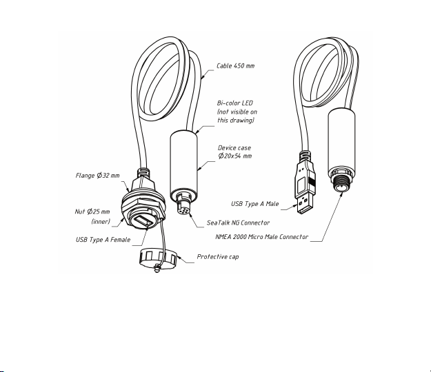
Figure 1. Drawing of YDNU-02RF and YDNU-02NM models of Gateway
Our devices are supplied with different types of NMEA 2000 connectors. Models containing R in the sufx
of model name are equipped with NMEA 2000 connectors compatible with Raymarine SeaTalk NG. Models
containing N in the sufx are equipped with NMEA 2000 Micro Male connectors. See connector drawings
in Appendix B.
— 7 —
Page 8
Gateways are equipped with high-quality USB Type A connectors with gold-plated
contacts. Model containing M in the sufx of the model name are equipped with
a male connector and must be used in dry place inside the cabin. These models
are designed for direct connection to a PC USB port (not waterproof). Models with F
a 1/2 bayonet locking mechanism. It ensures a IP67 waterproof connection (see chapter II).
in the sufx are equipped with a female connector with a protective cap and
Device parameter Value Unit
Average current consumption from USB (see note 1) 35 mA
USB interface specication supported 1.1, 2.0, 3.0 —
USB Device VID / PID 0483 / A217 hex
USB connection waterproof rating (see note 2) IP67 —
Supply voltage from NMEA 2000 network 7..16 V
Current consumption from NMEA 2000 network 13 mA
Load equivalency number 1 LEN
Galvanic isolation between NMEA 2000 and USB 2500 V
Cable length (between case and connector) 450 mm
Device case length 54 mm
Weight (models RM, NM / RF, NF) 37/51 g
Operating temperature range —20..+55 °С
Note 1: The Device is powered from the USB port, the power supply from the NMEA 2000
network is used for the isolated part of the network transceiver only.
Note 2: For YDNU-02RF and YDNU-02NF models, use YU-USB cables (not supplied with
the Device, see chapter II).
— 8 —
RMS
Page 9
II. Installation of Device and Connection to NMEA 2000 Network
The Device requires no maintenance. When deciding where to install the Device, choose a dry mounting
location. Avoid places where the Device can be ooded with water, as this can damage it.
The USB connector of YDNU-02RF and YDNU-02NF models may be mounted outside. In this case,
using YU-USB2-CPI-01-100 or YU-USB3-CPI-01-100 cables ensures an IP67 waterproof connection.
It is equipped with a protective cap used when no cable is connected (the connector is also compatible
with general USB Type A cables). You can order these cables at our web site.
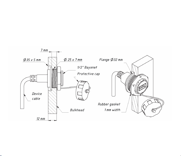
Figure 1. Mounting of YDNU-02RF and YDNU-02NF connectors on a bulkhead
When mounting on a bulkhead up to 7 mm, a hole only 25 mm in diameter is required to install
the connector. In case of wider bulkheads, a groove of 33 mm diameter at least is required. The groove
(and the hole) can be made with an inexpensive wood drill available world-wide (see Figure 2).
— 9 —
Page 10
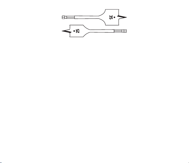
Figure 2. Inexpensive wood drill
YDNU-02RM and YDNU-02NM USB connectors must be used inside. These models are equipped
with USB Type A Male connectors and designed for direct connection with a PC USB port (not waterproof).
The Device is directly connected to the NMEA 2000 network backbone without a drop cable. Before
connecting the Device, turn off the bus power supply. Refer to the manufacturer’s documentation
if you have any questions regarding the use of connectors:
• SeaTalk NG Reference Manual (81300-1) for Raymarine networks
• Technical Reference for Garmin NMEA 2000 Products (190-00891-00) for Garmin networks
After connecting the Device, close the lock on the connection to ensure it is water resistant and rmly
secured.
The Device is powered from USB, the power supply from the NMEA 2000 network is used for the
isolated part of the network transceiver only. If you have no laptop or PC, you can power the Device with
any USB power adapter (not supplied with a Device) for test purposes.
When the USB cable is plugged in, the Device LED will signal with one ash with a duration of one half
second (see chapter IV for details) and the Device should appear in the list of NMEA 2000 (SeaTalk NG,
SimNet, Furuno CAN) devices or in the common list of external devices on the chart plotter (see Figure 1.
in chapter IX). Usually, access to this list is in the Diagnostics, External Interfaces or External devices menu
of the chart plotter.
— 10 —
Page 11
The Device allows sending of messages from PC applications to a NMEA 2000 network.
Product misuse or PC software bugs can cause ooding of the marine network or sending
of incorrect messages to the network and can lead to malfunction of critical ship systems. You
If you do not plan to control the marine systems from PC applications, it is recommended to block
all outgoing PC application messages with YDNU SILENT ON command (please, see chapter V for details).
must be sure that your software functions properly before a sea trial.
— 11 —
Page 12
III. Installation of USB Drivers and Connection to PC
The Device is connecting to USB port of a PC and is compatible with USB 1.1 protocol (1998) and later.
Therefore, it is compatible with all modern laptops and PCs. The Device is powered from the USB port
and you will see LED signals after connection (otherwise it means that the cable or USB port is damaged).
At the software level, the Device is a serial port (Virtual COM Port; USB device class 2, subclass 2). Such
devices do not require a special driver in Windows 10, Mac OS X and Linux; these operating systems
automatically use a system driver. In older Microsoft Windows versions, you should install a driver
(.INF le only, no code) which will tie the standard USBSER.SYS driver with a Device.
Serial ports are not intended for simultaneous use in multiple applications. If you can’t open
the Device’s port in an application, it can means that it is already opened in another one. This
limitation can be avoided with 3-rd party software.
In Microsoft Windows you must set the COM port number below 10 (COM1..COM9) for Device.
Otherwise, some applications will not be able to open the port and you will unable to manage
Device from command line (see chapter V). The COM port number may change each time
when you plug in the USB device into a new USB port. When a USB device is plugged into
the USB port where it was used previously, the operation system tries to assign the same
COM port number.
Connect the Device to a PC USB port and wait while the operation system on the PC searches and installs
a driver. The following sections contain important details about driver installation and Device conguration
in: Microsoft Windows 10, previous Microsoft Windows versions (Windows 7, Windows 8 and Vista),
Mac OS X, and Linux (Ubuntu).
Please read the section about your operation system carefully.
1. Microsoft Windows 10
Open «Device Manager» in the «Computer Management» applet of the Control Panel, and expand
the «Ports (COM & LPT)» as shown in the picture below.
— 12 —
Page 13
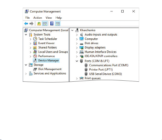
Figure 1. Windows 10 with a connected Device
You will see one or more USB serial devices. You can eject the USB cable to detect which one
is NMEA 2000 USB Gateway.
Please remember the port number which was assigned automatically to the Device. If the port number
is above COM9, you must change the port number to COM1 — COM9. Open the device’s properties, switch
to the «Port Settings» tab, and click the «Advanced…» button. Select another port number in the bottom
left corner (see Figure 2). Usually you can ignore the «in use» mark near the port number, it means that this
port was assigned to some other device previously; some computers have dozens of ports «in use» when
actually there are no devices connected.
— 13 —
Page 14
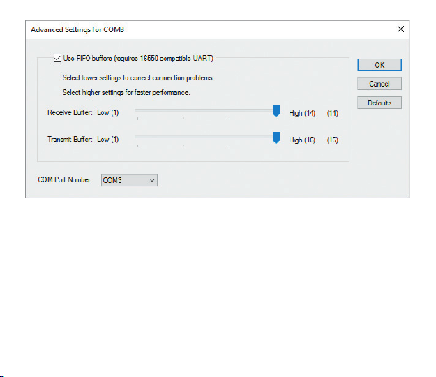
Figure 2. Advanced Settings of COM port
Port speed and related parameters have no practical effect on USB serial devices, so you can leave
the defaults for these parameters.
After changing the COM port number, you need eject the Device from the USB port and insert it back. Until
doing this, applications may fail to open the Device’s port.
2. Other Microsoft Windows versions
Open the «Device Manager» in the «Computer Management» applet of the Control Panel. If the Device
appears in the «Other devices» section after connection and has a yellow notication sign, then you need
to install a driver. You need only the .INF le (no code installation is required) which will link the Device
with the standard USBSER.SYS driver of Microsoft Windows.
— 14 —
Page 15
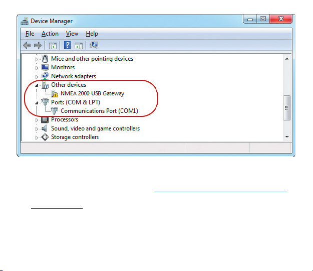
Figure 3. Windows 7 requires installation of driver
There are two options to get a driver for the Device:
• you can download a driver from our web site: http://www.yachtd.com/downloads/USBDRV.zip
• or you can download the Virtual COM Port driver from the STMicroelectrionics web site
http://www.st.com (type «STM32 Virtual COM Port Driver» in the search box on the site).
You should extract les from the ZIP archive to the disk folder.
Select «NMEA 2000 USB Gateway» and open the «Action \ Update Driver Software…» menu. Select
«Browse my computer for driver software» and «Let me pick from a list of device drivers on my computer»
in the opened window. Then select «Ports (COM & LPT)» as the device’s type (see Figure 4).
— 15 —
Page 16
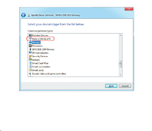
Figure 4. You should select «Ports (COM & LPT)»
When the device type is selected, you should select «STMicroelectronics» as the manufacturer
(the manufacturer of the Device’s core chip) and «STMicroelectronics Virtual COM Port» shown
in Figure 5.
If you have no «STMicroelectronics Virtual COM Port» in the list, click the «Have Disk…» button
and specify the folder with the previously extracted drivers (you should navigate to the subfolder
— 16 —
Page 17
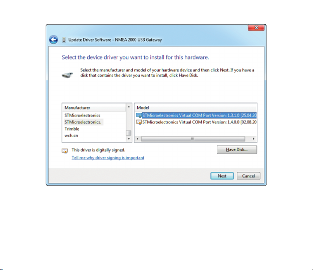
that corresponds to your operating system with a le named STMCDC.INF).
Figure 5. Driver selection
When the installation is done, please check an assigned COM port number. If the port number is greater
than COM9, you must to change it (please see the «Microsoft Windows 10» section of this chapter).
3. Mac OS X
After connecting the Device, click on the Apple icon and select the «About This Mac» menu item. Click
— 17 —
Page 18
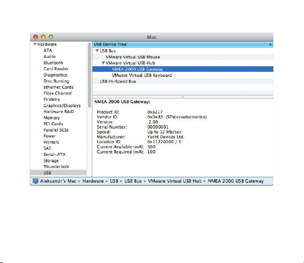
the buttons «More Info…» and «System Report…» in the opened window. Locate «NMEA 2000 USB
Gateway» in the USB subsection of Hardware section, as shown in Figure 6.
Figure 6. System Report on Mac OS X
This gateway has a serial number of 00090001, and the Device’s port to use in applications is:
/dev/cu.usbmodem00090001
You can type the following command in the terminal to check the port name:
ls /dev/cu.usbm*
— 18 —
Page 19

For a Device with serial number 00090001, the command’s output will be:
/dev/cu.usbmodem00090001
4. Linux (Ubuntu)
The Device works with a system CDC ACM driver. After connection of the Device, type the following
command in the terminal:
dmesg
The output’s tail contains the Device’s properties and port name:
[98.454005] usb 2-2.1: Product: NMEA 2000 USB Gateway
[98.454009] usb 2-2.1: Manufacturer: Yacht Devices Ltd.
[98.454013] usb 2-2.1: SerialNumber: 00090001
[98.461125] cdc_acm 2-2.1:1.0: ttyACM1: USB ACM device
The port name for use in applications is /dev/ttyACM1 (printed in the last line of the output). You can type
the following command in the terminal to check the port name:
ls /dev/ttyA*
Note that after connection, the modem manager can open a Device for a minute and the Device
will not be available for use in other applications at this time. In this case, you can instruct the modem
manager to ignore the Device using the USB identiers of the product (VID and PID):
echo ATTRS{idVendor}==\«0483\» ATTRS{idProduct}==\«a217\»,
ENV{ID_MM_DEVICE_IGNORE}=\«1\» > /etc/udev/rules.d/ydnu.rules
sudo udevadm control –reload
— 19 —
Page 20
IV. LED Signals
The Device is equipped with a bi-color LED that indicate the Device’s state. Note, serial devices
are intended for use by one application at a time and when the device is used in one application, you cannot
use it in another application or send a command from the console (this is described in the next chapter)
or update the rmware.
LED signals during a rmware update are described in chapter IX.
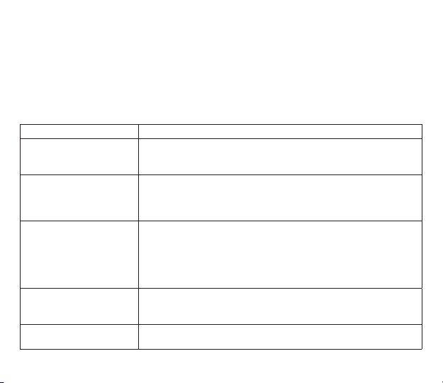
Table 1. Signals during a normal operation
LED Signal Device State
One 0.5 second signal when
USB cable is connected
Two 0.5 second signals
within a 3 second period
Four very rapid signals with
a period of 1.5 second
Constant GREEN signal Device can not send data to application more than 3 seconds (application
One-second GREEN signal Operation mode command is received and accepted (see the next chapter
Device is powered. RED signal indicates that «silent mode» is active
and Device can send data to PC only, GREEN that Device in normal mode
and can send data in both directions (see chapter V).
Device is connected to PC, port is not opened by an application. First
signal is GREEN if data from NMEA 2000 are received during the
period, RED otherwise. Second signal is GREEN if no data transmitted or
received over USB, RED otherwise.
Port is opened by an application. First signal is GREEN if data was
received from NMEA 2000 during the period (otherwise RED). Second
is GREEN if nothing was transmitted to NMEA 2000 by the Device
during the period. Third is GREEN if data was transmitted to PC during
the period. 4th is GREEN if no data was received from PC during
the period.
hangs), but port is still opened by application. Connection with
PC application detected by the state of DTR signal.
for details).
— 20 —
Page 21
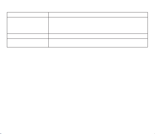
Table 1 continued
LED Signal Device State
Three RED signals per
second for a 10 second
period
Device is powered, but is not connected with a PC. It is possible that drivers
are not installed or cable is damaged or Device is disabled («ejected»)
in PC settings or Device is connected to USB power adapter or with
«power only» USB cable.
Three second GREEN signal Recording of diagnostics data is turned on.
Three-second RED signal Recording of diagnostics data is turned off (EEPROM buffer is full
or service mode is turned on).
— 21 —
Page 22
V. Configuration of Device Operation Modes
This section describes how to switch the output protocol (operation mode) of Device and how to switch
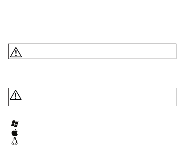
it from bi-directional mode (factory setting, normal mode) to «read only» mode (silent mode).
The Device supports four operation modes: 0183, RAW, N2K and AUTO (see Introduction). The default
operation mode is AUTO and we recommend keeping this setting. The technical aspects of AUTO mode
functionality are available in chapter X.
Serial ports are not intended for simultaneous use in multiple applications. If you can’t open
Device’s port in an application, it can means that it is already opened in another one.
This limitation can be avoided with 3-rd party software.
The change of the operation mode may be required for advanced users, for example, to view network
messages in RAW format with terminal application.
To switch the mode, you should send a special command, «YDNU MODE», with a required mode name
to the Device’s serial port. You can do it with the built-in «echo» command in the command line (shell)
in Microsoft Windows, Mac OS or Linux.
In Microsoft Windows, you must set the COM port number below 10 (COM1 – COM9) for Device
(see III.1). Otherwise, you will be unable to manage the Device from a command line.
The COM port number may change each time when you plug in a USB device into a new USB
port.
For example, to switch operation mode to 0183, run the following command (all characters of Device
command must be uppercase) in the command line (shell, command prompt) of the operation system:
echo YDNU MODE 0183 > COM3
echo YDNU MODE 0183 > /dev/cu.usbmodem00090001
stty -F /dev/ttyACM1 hupcl
echo YDNU MODE 0183 > /dev/ttyACM1
— 22 —
Page 23
Where:
• echo is a built-in command of an operating system;
• YDNU MODE 0183 is a special command sent to the Device (turn on 0183 mode);
• > (greater-than symbol) is an operator that redirects command output.
We used the same port names (specied after the output redirection sign >) above, as were used
in the examples of chapter III. The command will be conrmed by a one second green signal of the LED
and the value set will be saved to the EEPROM.
The special command YDNU SILENT ON does not actually change the operation mode, but it prohibits
sending of all outgoing messages from PC applications to the NMEA 2000 network, making the Device
«read-only». We will call this the «silent mode» for simplicity.
echo YDNU SILENT ON > COM3
echo YDNU SILENT ON > /dev/cu.usbmodem00090001
stty -F /dev/ttyACM1 hupcl
echo YDNU SILENT ON > /dev/ttyACM1
This setting is recommended if you are not planning to control the marine systems from PC applications.
It protects the NMEA 2000 network from the threat of ooding caused by an incorrectly congured
PC application. When the «silent mode» is on, the LED signal when the Device powers on is red, otherwise
green (see chapter IV).
The command YDNU SILENT OFF returns the Device to the normal bi-directional mode. Both
(on and off) commands are conrmed by a one second green signal of the LED and the setting will be saved
to the EEPROM.
— 23 —
Page 24
VI. Terminal Access to Service Menu
The Service menu allows you to change the Device’s settings and view diagnostics data. Note that
we recommend using the application’s settings to lter NMEA messages instead of the Device settings,
because Device settings have a global effect and sometime later you may be surprised that some things
are not working in other applications.
To begin, you should put the Device in the service mode with the YDNU MODE SERVICE command
from the operating system command line (shell). For example (please, see the explanation of command
syntax in the previous chapter):
echo YDNU MODE SERVICE > COM3
echo YDNU MODE SERVICE > /dev/cu.usbmodem00090001
stty -F /dev/ttyACM1 hupcl
echo YDNU MODE SERVICE > /dev/ttyACM1
The command will be conrmed by a signal of Device’s LED. Note that the service mode will be active until
you set the operation mode or turn the Device off.
To access the service menu, you need a terminal application. Unlike Mac OS X and Linux,
Microsoft Windows does not contain a terminal application (since Windows Vista). We recommend
the freeware program, Putty, which is available for Microsoft Windows and Linux. You can download
it here: http://www.putty.org/
When the Device is in the service mode, type the following command from command line or shell to access
the service menu:
putty.exe -serial COM3
screen -a /dev/cu.usbmodem00090001
screen -a /dev/ttyACM1
stty -F /dev/ttyACM1 hupcl
— 24 —
Page 25
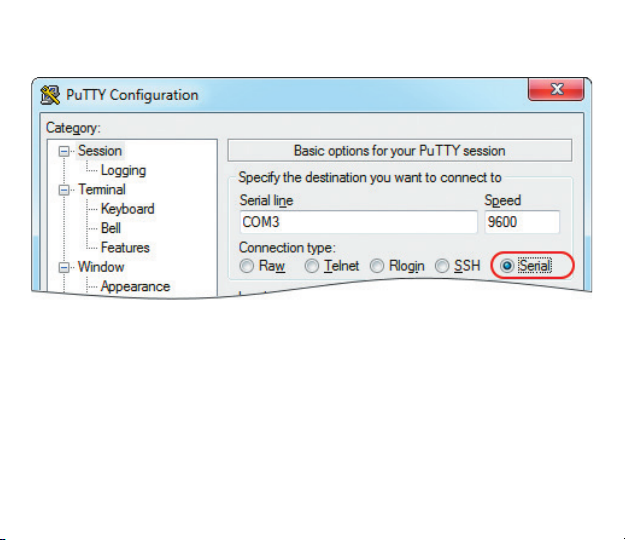
If you are using Putty, you can also launch it without parameters, tick the «Serial» radio button and type
the port name in the «Serial line», as shown in Figure 1. Leave all other settings unchanged.
Figure 1. Putty is ready to open the COM3 serial port
After connection, you will see the welcome screen of service menu of Device (see Figure 2 on the next page).
If the welcome screen does not appear, make sure that the device is switched into the service mode
and the right serial port name used for the connection.
— 25 —
Page 26
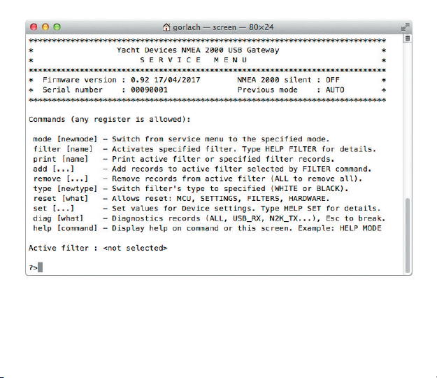
Figure 2. Welcome screen of the service menu
— 26 —
Page 27

VII. Service Menu Commands and Device Settings
The Service menu is like a command line of Windows and MS-DOS or Mac OS X or Linux shell. You
should type commands (any register is allowed) and in case of a mistake, you can erase the last character
with the Backspace button.
The welcome screen (see Figure 2 in the previous chapter) is displayed once after connection from
the terminal application. To display the welcome screen again, type the HELP command and press
the Enter button. To get help with a command, type HELP and the command for which you would like to see
the help. For example, type HELP MODE and press Enter to get help for the MODE command.
1. MODE command and «exit» from service mode
The command MODE changes the operation mode of the Device. Four modes are available: 0183, N2K,
RAW and AUTO (please see the Introduction chapter for details).
To «exit» from the service mode, you should activate some other operation mode with the MODE command.
For example, after the command MODE 0183, you will see NMEA 0183 sentences in the terminal window:
?>MODE 0183
NOTE: 'Auto' mode (recommended) is turned OFF, because you manually switched
to another mode. Switching to '0183' mode, press Esc to switch back...
$--GGA,173412.00,4146.5882,N,07029.6988,W,2,13,0.80,0.00,M,0.00,M,0.00,0000*7F
$--GLL,4146.5894,N,07029.6952,W,173412.02,A*02
$--GSA,A,3,02,03,06,09,12,17,19,22,23,24,28,,0.7,0.7,0.4*2F
$--RMC,173412.00,A,4146.5882,N,07029.6988,W,6.9,62.9,280816,15.0,W,D,V*5F
$--ZDA,173412.04,28,08,2016,00,00*70
$--MWV,357.7,R,13.2,M,A*08
This means that 0183 mode is activated and you can close the terminal session. Or you can press
the Esc button to return to the service menu.
You can also close the terminal program and set an operation mode from a command line, as described
in chapter V. Note that service mode is active while the Device is powered, so you can unplug the USB cable
— 27 —
Page 28

and plug it back in to return to the previous mode.
2. Filtering of messages (FILTER, PRINT, TYPE, ADD and REMOVE commands)
The Device has eight lter lists, which allows limiting the set of messages passed from the NMEA 2000
network to a PC application (incoming has RX sufx) and messages passed from the PC application
to NMEA 2000 network (outgoing, has TX sufx):
• global_rx - Global lter for incoming NMEA 2000 messages transmitted to PC
• global_tx - Global lter for messages transmitted to NMEA 2000 network from PC
• raw_rx - For incoming messages transmitted to PC in RAW mode
• raw_tx - For messages received from PC in RAW mode
• n2k_rx - For messages transmitted to application in N2K mode
• n2k_tx - For messages received from application in N2K mode
• 0183_rx - NMEA 0183 sentences passed to application in 0183 mode
• 0183_tx – NMEA 0183 sentences accepted from application in 0183 mode
For operation with lter lists, you should be familiar with NMEA 2000 and NMEA 0183. Otherwise,
we recommend not modifying any lters and using the lter setting in the PC application. In case of troubles
with lters, you can reset the list of lters to the factory settings using the command RESET FILTERS
or RESET SETTINGS, which resets all settings including lters.
To view or modify the lter, you should «activate» (select) it with the FILTER command rst. For example:
FILTER GLOBAL_RX
The PRINT command without parameters prints records of the active lter. To view a non-active lter,
specify its name after the command:
PRINT GLOBAL_TX
— 28 —
Page 29
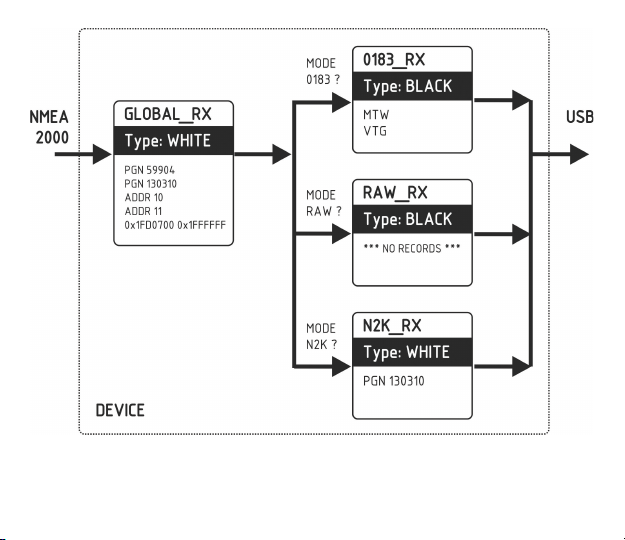
Figure 1. Example of conguration of incoming lters
— 29 —
Page 30

Each lter list has a switchable type: WHITE or BLACK. A message is passed thru the WHITE lter
if it contains a record matched with a message. And the reverse for BLACK. In the factory settings, all
lter lists are empty and are of BLACK type, so all messages are passed through lters. To change the type
of the active lter, use the TYPE command. For example:
TYPE WHITE
0183 lters contain 3-char NMEA 0183 sentence formatters. According the standard, a NMEA 0183
sentence start with a $ or ! symbol, followed by two-character talker ID and 3-char sentence formatter.
These elements are followed by data elds (after the comma). The sentence is nished by a check sum
after the * (asterisk) symbol.
Gateway with factory settings using «YD» talker ID, it can be changed with SET command (see VII.4).
The Device uses 3-char sentence formatters only for ltering. The following sentences matches to GLL
and VDM records (sentence formatters):
$GPGLL,4146.5894,N,07029.6952,W,173412.02,A*02
!AIVDM,1,1,,B,ENk`smq71h@@@@@@@@@@@@@@@@@=MeR6<7rpP00003vf400,4*5F
Other lters actually contain pairs of 29-bit message identiers and a mask. The identier is compared
by processing the NMEA 2000 message identier and the second value (mask) denes the comparison
concerning which bits are signicant.
The identier contains a PGN (Parameter Group Number, described in NMEA 2000 Standard)
and a source device address. PGN and ADDR keywords may be used to modify these lists more easy.
You can use decimal and hexadecimal numbers (which start with a 0x prex).
Multiple parameters may be passed to a command. The following examples add and remove all added
records (note that right column syntax is differ):
— 30 —
Page 31

FILTER GLOBAL_RX
ADD PGN 130310 130311
REMOVE PGN 130310
REMOVE 0x1FD0700 0x1FFFF00
ADD ADDR 0x10
REMOVE ADDR 16
When a PGN keyword is used (not applicable to 0183 lters), the Device adds or remove records with
the mask 0x1FF0000 for addressed NMEA 2000 messages and 0x1FFFF00 for global-addressed messages.
For example, to add the records listed in the GLOBAL_TX lter in Figure 1, you can enter the following
commands:
FILTER GLOBAL_TX
ADD PGN 59904 130310
ADD ADDR 10 11
ADD 0x1fd0700 0x1ffffff
FILTER 0183_TX
ADD XDR GLL VDO
REMOVE XDR
REMOVE GLL VDO
The actual content of the lter will be (type PRINT without parameters):
Message ID Mask Comment
---------- ---------- -------------------0x00EA0000 0x01FF0000 PGN 59904
0x01FD0600 0x01FFFF00 PGN 130310
0x0000000A 0x000000FF ADDR 0x0A (ADDR 10)
0x0000000B 0x000000FF ADDR 0x0B (ADDR 11)
0x01FD0700 0x01FFFFFF
To remove the third record from the list, you can type any of following commands:
REMOVE 0x0A 0xFF
REMOVE ADDR 0x0A
REMOVE ADDR 10
The command REMOVE ALL clears the current lter (removes all records) and switches its type to BLACK.
— 31 —
Page 32

Let’s check the processing of a message with PGN 130310 (Environmental Parameters) by lters
in the conguration shown in Figure 1. It will be passed by the Global_Tx lter (lter type in Figure 1
is white). This message produces the sentences XDR and MTW in 0183 mode (see Appendix D, Table 1),
so if this operation mode is active, we’ll get the XDR sentence in the PC application, because the MTW
sentence is blocked in 0183_Tx (type: black). In RAW or N2K mode, the 130310 message will be passed
by the Raw_Tx and N2K_Tx lters.
The message with PGN 130314 (Actual Pressure) will pass the Global_Tx lter only if sent by a device
with NMEA 2000 address 10 or 11. It passes the Raw_Tx lter in RAW mode (because lter
in this conguration pass all messages), but will be blocked by the N2K_Tx lter in N2K mode (this lter
passes 130310 messages only).
3. RESET command
This command accepts one argument:
• RESET FILTERS. Removes all records from all lters and switches types to BLACK (see previous
section). This corresponds to the factory conguration of lters.
• RESET SETTINGS. This command resets all settings to factory values (including lters).
• RESET HARDWARE. EEPROM contains a copy of rmware le uploaded at the factory. After
any rmware update, you can return to your initial rmware and return your Device to factory state.
All settings are reset during this operation.
• RESET MCU. Reboot the Device.
4. SET command
The following settings can be set ON or OFF with this command:
• SILENT — silent mode, see Chapter V for details;
• RAY_AUTOPILOT — control of Raymarine autopilots from NMEA 0183;
• WPT_CONFIRM — automatic conrmation when changing the waypoint (works with Raymarine
autopilots only);
— 32 —
Page 33

• RMB_N2K_VAR — using of NMEA 2000 variation for RMB processing if an HDG or RMC sentences
is not available;
To learn more about autopilot control, see the Chapter XI. Here is an example of how to turn on and
off the silent mode, type:
SET SILENT ON
SET SILENT OFF
The TALKER_ID setting (see VII.2) accept two letters (AA..ZZ) or -- as argument, example:
SET TALKER_ID GP
After the command above, sentences sent by gateway will looks like $GPGLL.
The WIND_CALC setting is used to calculate the true wind. The wind sensor always measures apparent
wind; true wind angle is calculated using SOG or STW data and true wind direction requires COG
or heading. A chart plotter can join all these data and send calculated values to NMEA 2000, but usually
TWD, TWA and TWS are not available.
Historically, STW/HDG are used to calculate true wind. However, this is not correct in places with
strong current, and the «true» value of true wind can be obtained using the SOG/HDG pair. Therefore,
our gateways offers four options: SOG/HDG (if you love truth), SOG/COG (if you have GPS only),
STW/HDG (if tradition is most important), or you can disable calculations.
The WIND_CALC accepts the following arguments: ANY (factory setting), HDG_STW, COG_SOG,
HDG_STW and DISABLED. In the last case the gateway reports true wind data only if they are calculated
by another device available on NMEA 2000 network. The default setting «ANY» means that the gateway
will detect what data are available on the network and will calculate true wind data using the best possible
option.
To get the current value, type the command with the setting name only:
SET SILENT
— 33 —
Page 34

The XDR sentence is used to transfer data from sensors, tanks, engines, etc. This sentence contains
the sensor’s text identier (name), which was not dened by NMEA Standard until end of 2018. This led
to the invention of names by every company on the market. For example, B&G uses “AIRTEMP” to send
air temperature data, OpenCPN software uses “TempAir”, Maretron uses “ENV_OUTSIDE_T”,
and the NMEA 0183 Standard 4.11 denes “Air”.
Type the command
SET XDR
to list available settings for XDR sentence. With these settings you can dene names used in XDR to provide
compatibility with software or hardware. The length of the name is limited to 16 characters. An empty name
means that data will not be sent in XDR sentence.
5. DIAG command
This command is used to display the record of diagnostic data (see next chapter for details).
Due to the possibility of a large amount of data, the DIAG command requires at least one argument:
• ALL. Print all data (may take a minute or two, press Esc to brake).
• SETTINGS. Dump of settings copy, saved at beginning of recording.
• USB_RX. Data received from PC.
• USB_TX. Data transmitted to PC.
• N2K_RX. Data received from NMEA 2000 network (before lters).
• N2K_TX. Data actually transmitted to the network.
You can combine these arguments in any order, for example, to view all USB data:
DIAG USB_RX USB_TX
You can break the output at any moment by pressing the Esc button. Note that binary data
(NMEA 2000 messages) are printed in hexadecimal, and text data (NMEA 0183 sentences) is printed
as text.
Sample of data output:
— 34 —
Page 35

00:00:47.812 USB TX $--MWV,355.1,R,26.7,M,A*0F
$--DBT,59.1,f,18.03,M,9.8,F*27
$--MTW,22.9,C*1A
00:00:47.814 N2K RX DF80501 E0 2F FF 91 42 00 34 BA
00:00:47.815 N2K RX DF80501 E1 25 80 41 26 FB 85 38
00:00:47.816 N2K RX DF80501 E2 CC 05 80 D2 4E 58 3D
00:00:47.816 USB TX !AIVDM,1,1,,B,35NH9UP2h:Jv<8>GoHB5j0ah03j0,0*62
!AIVDM,1,1,,A,ENk`slI13h@@@@@@@@@@@@@@@@@=MlIV<8<dP00003vf000,4*42
00:00:47.816 N2K RX DF80501 E3 93 37 F6 6A 26 23 00
00:00:47.817 N2K RX DF80501 E4 00 00 00 00 10 FC 0B
00:00:47.818 N2K RX DF80501 E5 4E 00 69 00 3C F3 FF
00:00:47.819 N2K RX DF80501 E6 FF 00 FF FF FF FF
00:00:47.820 N2K RX 19FA0401 80 87 FF FF 0B 02 68 12
— 35 —
Page 36
VIII. Recording of Diagnostics Data
With the command YDNU DIAG (sent in the same way as mode operation commands, see chapter V)
you can start recording diagnostics data.
Serial ports are not intended for simultaneous use in multiple applications. You must close your
marine application (or turn off the Device’s port in the application settings) before sending
the command to Device.
The Device conrms the command YDNU DIAG by a three-second green signal from the LED, saves
a copy of current settings (including lters) to a diagnostic record, and after 3 seconds starts recording
all data trafc on the NMEA 2000 and USB interfaces. Data are saved to the EEPROM buffer of 1 MB size.
One second of recording usually takes 2 – 10 KB and the buffer is enough for 2-10 minutes of recording.
To stop recording, you can send a YDNU MODE SERVICE command. Recording also stops when free space
in the EEPROM buffer is nished. The Device informs you with three-second red signal from the LED
when stops recording.
Example of starting and stopping of recording in Microsoft Windows (please, see explanation of command
syntax in the chapter V):
C:\>echo YDNU DIAG > COM3
C:\>echo YDNU MODE SERVICE > COM3
Note that the buffer stores only one diagnostics record, and starting a new recording overwrites
the previous diagnostics record.
To save the recorded diagnostics data to a le, you can print the diagnostics data with the DIAG ALL
command in the service menu (see VII.5) with session logging turned on in your terminal application.
All diagnostics data will be saved to a session log le.
In Mac OS X and Linux, you can turn on session logging with the –L key of the screen command:
— 36 —
Page 37

screen -L /dev/cu.usbmodem00090001
screen -L /dev/ttyACM1
In Putty, (available for Microsoft Windows and Linux), select «Logging» in the Category tree in the «Putty
conguration window» and tick the «All session output» radio button. Then choose output le location.
In the terminal session, run a DIAG ALL command and wait until all data is printed. Close the terminal
program, locate the session log le (in Mac OS X and Linux the le will be located in the current folder
and will have a name like «screenlog.0»). It may be big (2—3 MB) and we recommend packing
it in a ZIP archive before sending by e-mail.
— 37 —
Page 38
IX. Firmware Updates
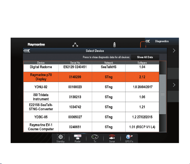
You can check the current rmware version on the welcome screen of the service menu (see Figure 2
in chapter VI) or in Device information in the list of NMEA 2000 (SeaTalk NG, SimNet, Furuno CAN) devices
or in the common list of external devices on the chart plotter (see third line in Figure 1). Usually, access
to this list is located in the Diagnostics, External Interfaces or External devices menu of the chart plotter.
Figure 1. Raymarine c125 MFD devices list with Device (YDNU-02)
— 38 —
Page 39
The rmware update leaves Device’s settings intact. You will not damage the Device in the event of power
failure or any other shutdown at any state of rmware update procedure.
To update Device rmware, you should copy the update le (with .BIN extension) to the Device’s port:
copy /B UUPDATE.BIN COM3
cp UUPDATE.BIN /dev/cu.usbmodem00090001
cp UUPDATE.BIN /dev/ttyACM1
We used the same port names above, as were used in the examples in chapter III.
File uploading takes 3-10 seconds, during this time Device’s LED will be off. The Device informs
about upload result with the following LED signals (three fast ashes in one second):
• Green, green, green. File is successfully uploaded to Device’s EEPROM.
• Red, red, green. Device already contains rmware of this version.
• Red, green, red. File header is correct, but uploaded le is corrupted.
If the Device produces no special signals after copying the le, it means that the le was not recognized
by the Device as a rmware update le. This may be caused by copying a ZIP archive with rmware update
instead of the rmware update BIN le.
After successful upload followed by three green signals, the Device reboots to pass control to the bootloader.
The bootloader will make some additional checks, and if uploaded le is correct, the Device’s LED
will be turned off for 5-15 seconds, and a 10 second series of green and red ashes after that will indicate
that rmware is updated. After that, the Device returns to a normal operation. If the le is incorrect,
the bootloader returns control to the rmware program without any visual cues.
— 39 —
Page 40
X. Programming Considerations
We welcome software developers who are interested in supporting Gateway protocols, and especially
RAW mode protocol. We promise free technical support within reasonable limits and free testing
of your products, even if you do not have a Device.
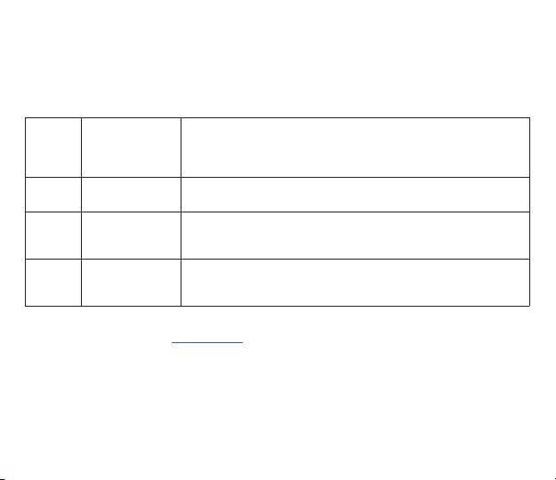
Mode Recommended
0183 24 0A Mode can be activated also by sending a valid NMEA 0183 sentence
RAW 30 0A Mode can be activated also by sending of valid message in RAW format.
N2K 10 02 A1 03 11 02
activation
sequence
(hexadecimal)
00 49 10 03
1. A copy of Appendix B of NMEA 2000 Standard must be purchased from the National Marine
Electronics Association (www.nmea.org) to develop software which supports N2K or RAW mode.
2. The application must enable DTR signaling or manually set the DTR signal after opening
the Device port and reset the DTR signal on close. In Microsoft Windows, this can be done
with EscapeCommFunction and SetCommState API functions.
3. You should assume that the Device functions in AUTO operation mode, and you must not try
to switch the mode with the YDNU MODE command without permission from the user if a mode
that is non-compatible with your application is active.
Comments
starting with ‘$’ (hexadecimal 24) or ‘!’ (hexadecimal 21) symbols.
Or by any sequence starting with ‘0’..’9’, ‘a’...’f’ or ‘A’..’F’ characters.
See appendix E for details.
This sequence is used in the Canboat application to turn on «Receive
All Messages» mode on ActiSense NGT. Any sequence starting
with 10 02 bytes will activate N2K mode on the Device.
Table 1. Recommended mode activation sequences
— 40 —
Page 41

4. The application must send a mode activation sentence (see Table 1) immediately after opening
a port. Recommended sentences do not cause sending of any message to NMEA 2000 network.
In the AUTO mode, the Device analyzes rst bytes received from the application for the rst
2000 milliseconds after the port is opened. If no data are received during that 2000 milliseconds,
or received data cannot be interpreted as an activation sentence, the Device activates 0183 mode.
5. The application should avoid sending messages byte-by-byte. It is recommended to prepare
a message (or even set of messages) in a memory buffer rst and send it to the port with one call.
Byte-by-byte calls can cause a series of one-byte USB packets that can have negative performance
effect.
— 41 —
Page 42

XI. Autopilot Control and Settings
This chapter describes how to control NMEA 2000 (SeaTalk NG) autopilot from the application using
NMEA 0183 protocol.
Modern autopilots have the following modes:
• Standby. In this mode, autopilot is not engaged to the vessel control.
• Auto. The autopilot has a xed course to steer.
• Wind. The autopilot steers the boat at a specied angle to the wind.
• Waypoint. The autopilot steers the boat to the specied waypoint.
• Route or Track. The autopilot steer the boat by a specied route.
The difference in the last two modes is that autopilot not only maintains the right direction to the waypoint,
but also tries to follow the line from the previous to the next waypoint.
When NMEA 2000 autopilot is controlled from a NMEA 0183 application, it must receive:
• position of the destination waypoint (from RMB sentence);
• course from the position to the destination waypoint (APB and/or RMB);
• cross track error, means the distance and direction from the current position to the route (APB
and/or RMB and/or XTE).
Depending on the implementation, the NMEA 2000 autopilot can also use the following data (and not
only):
• vessel heading (HDG sentence), but in most systems the heading sensor is connected directly
to the autopilot;
• rate of turn (ROT sentence);
• position, course and speed over ground (RMC sentence).
To control the autopilot, Gateway should receive APB and RMB sentences from the application. Gateway
also needs to have magnetic variation data, which can be obtained from HDG or RMC sentences or from
— 42 —
Page 43

the NMEA 2000 messages (must be turned on in the Gateway settings).
If your NMEA 2000 network has GPS data, it can use data already available on NMEA 2000 and sending
of the ROT, HDG and RMC sentences from the application may not be required. It is better to send minimal
data from a PC to the NMEA 2000 network if possible.
Depending on the autopilot sensitivity settings, autopilot can control your vessel smoothly or aggressively.
The application only provides the situation (where is the waypoint and how far we are from the route),
but the course to steer and the rudder angle are dened by the autopilot logic.
Switching of waypoints is the work of the application. If the arrival radius is set to 1 NM, application
can switch to the next waypoint when the current point is still a mile away. If your route is circular
or approximately so, the application can unexpectedly switch from the rst point to the last. You should be
familiar with your application settings and test how the system works on the open water.
The autopilot can warn you or ask for your conrmation when the application changing the waypoint.
It depends on autopilot settings. When the application terminates the navigation, it usually stops sending
APB and RMB sentences. Autopilot usually switches to Auto mode and signals about that.
Raymarine autopilots use proprietary messages to control. The Gateway was tested with the two systems,
but we also expect that it will work well with all other Raymarine SeaTalk NG autopilots:
• Raymarine C90W chartplotter, Raymarine SPX SmartPilot SPX30 and Raymarine ST70 Pilot Head;
• Raymarine c125 chartplotter (LightHouse 17), Raymarine EV-1 Course Computer and Raymarine
ACU200 Actuator Unit.
To control Raymarine autopilot:
• its support must be turned on in the settings (see VII.4), because it is turned off by default;
• autopilot must be initially set to the Auto mode to be controlled from the application;
• the application must provide APB, RMB and RMC sentences;
• the application should provide an HDG or RMC sentences or using of NMEA 2000 variation must be
on in the settings (see VII.4).
— 43 —
Page 44

When the route or waypoint is activating in the application, autopilot switches to the Track mode from
Auto. If automatic conrmations are off (default settings, see VII.4), the chart plotter and pilot head will ask
for the conrmation when waypoint is changing. When the application terminates the navigation, autopilot
returns to the Auto mode.
It is impossible to switch from Track mode to Auto when the application controls the autopilot, because
it will return it to the Track mode after a 5-second delay. To take control in an emergency, switch
the autopilot to Standby mode.
— 44 —
Page 45
APPENDIX А. Troubleshooting
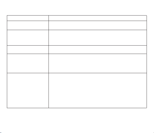
Situation Possible cause and correction
LED does not signal when
USB cable is connected
All Device signals are red
with 10-second interval
PC software does not work
as expected
Application cannot open
Device port; write and/or
access errors when sending
commands to Device
Device does not accept
operation mode commands
USB cable or USB port is damaged. Replace the cable and/or try
to connect Device to another port.
Device is powered on, but is not connected with a PC (drivers
are not installed; device is disabled in PC settings; etc.). If you connected
the Device to a new USB port, re-connect it to the port used previously.
Please see chapter IV Table 1 for details.
Record diagnostics data (see chapter VIII) and send it with a PC software
screenshot to technical support.
Check the LED signals. If Device signals that the port is already opened
by an application, close all applications that can use the Device port.
In Linux, check the modem manager settings (see III.4). In Linux
and Mac OS X, be sure that you have permissions on the Device port
(see operation system manual).
If the LED signals that port is already opened by an application,
but you can open the Device’s port with the terminal or any program,
this may mean that there is incorrect handling of the DTR signal by
the PC software. Try the following commands (replace the port name
with your own) in operation mode command in Windows, Mac OS X,
Linux:
• MODE COM3 DTR=ON
• stty -F /dev/cu.usbmodem00090001 hupcl
• stty -F /dev/ttyACM1 hupcl
— 45 —
Page 46
APPENDIX B. Device Connectors
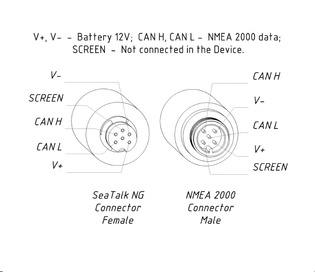
Figure 1. NMEA 2000 connectors of the YDNU-02RM and YDNU-02RF (left), and connectors of the
YDNU-02NM and YDNU-02NF (right) models
— 46 —
Page 47
APPENDIX С. NMEA 2000 Messages Supported by Device
The Gateway can pass any message from NMEA 2000 to a PC application and in the opposite direction.
«No» in the table below means that the Device will not process these messages during service
communication with other devices on the network. Note that service communications are not affected
by the «silent mode» of the Device (see chapter V).
Appendix D contains the list of messages processed during conversion from NMEA 2000 to NMEA 0183
and from NMEA 0183 to NMEA 2000.
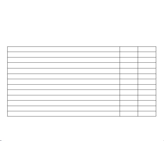
Message Receive Transmit
ISO Acknowledgment, PGN 59392 (0xE800)
ISO Address Claim, PGN 60928 (0xEE00)
ISO Commanded Address, PGN 65240 (0xFED8)
ISO Transport Protocol (CM), PGN 60416 (0xEC00)
ISO Transport Protocol (DT), PGN 60160 (0xEB00)
ISO Request, PGN 59904 (0xEA00)
GNSS Position Data, PGN 129029 (0x1F805)
Local Time Offset, PGN 129033 (0x1F809)
NMEA Group Function, PGN 126208 (0x1ED00)
PGN List Group Function, PGN 126464 (0x1EE00)
Product Information, PGN 126996 (0x1F014)
System Time, PGN 126992 (0x1F010)
— 47 —
Table 1. Messages supported by Device
Yes Yes
Yes Yes
Yes No
Yes No
Yes No
Yes No
Yes No
Yes No
Yes No
No Yes
Yes Yes
Yes No
Page 48
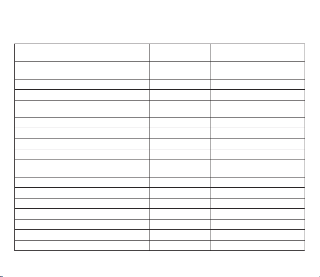
APPENDIX D. Conversions Between NMEA 2000 and NMEA 0183
Table 1. Conversions from NMEA 2000 to NMEA 0183
NMEA 2000 PGN NMEA 0183
65311 Magnetic Variation (Raymarine
Proprietary)
126992 System Time ZDA, GLL See also PGN 129033
127233 Man Overboard Notication (MOB) MOB
127237 Heading/Track Control APB, HSC Use PGN 129284, 129283
127245 Rudder RSA Two rudders supported
127250 Vessel Heading HDG, HDM, HDT See note (4)
127251 Rate of Turn ROT
127258 Magnetic Variation — See note (4)
127488 Engine Parameters, Rapid Update RPM, XDR, DIN,
127489 Engine Parameters, Dynamic XDR, DIN See note (6)
127493 Transmission Parameters, Dynamic DIN, PGN See note (6)
127501 Binary Status Report DIN See note (6)
127505 Fluid Level DIN, PGN See note (6)
127508 Battery Status DIN, PGN See note (6)
128259 Speed, Water referenced VHW Also may be used in RMC, VTG
128267 Water Depth DBT, DBS, DPT
Sentence
— See note (4)
PGN
— 48 —
Comment
if possible
See note (6)
Page 49
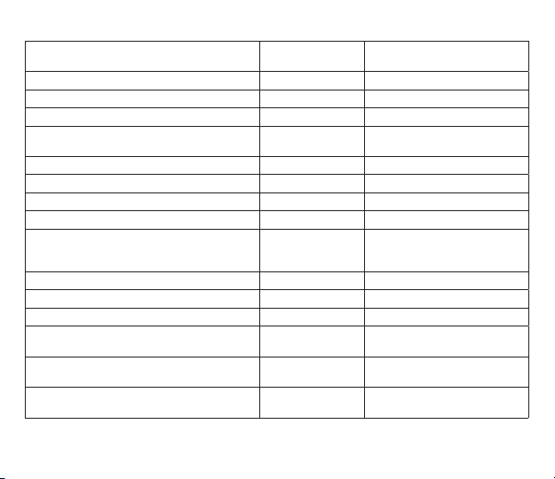
Table 1 continued
NMEA 2000 PGN NMEA 0183
Sentence
Comment
128275 Distance Log VLW
129025 Position, Rapid Update GLL Also use PGN 126992 or 129029
129026 COG & SOG, Rapid Update VTG Also used in RMC
129029 GNSS Position Data GGA, GLL, RMC,
ZDA
See also PGN 129033
129033 Local Time Offset — Time offset is used in ZDA
129044 Datum DTM
129283 Cross Track Error XTE
129284 Navigation Data RMB, HSC Use 129283, 129029 if possible
129285 Navigation — Route/WP information — Waypoint names from this
message are used in RMB
and APB sentences
129291 Set & Drift, Rapid Update VDR
129539 GNSS DOPs GSA PGN 129540 is also required
129540 GNSS Sats in View GSV, GRS PGN 129539, 129029 required
130066 Route and WP Service — Route/WP—
List Attributes
130067 Route and WP Service — Route —
WP Name & Position
130074 Route and WP Service — WP List —
WP Name & Position
RTE Use waypoints from 130067
WPL
WPL
— 49 —
Page 50
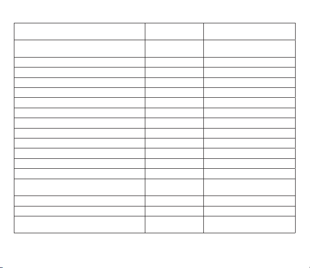
Table 1 continued
NMEA 2000 PGN NMEA 0183
130306 Wind Data MWD, MWV,
Sentence
VWR, VWT
Comment
See note (3). Also used in MDA.
130310 Environmental Parameters XDR, MTW, MDA See note (1), (5)
130311 Environmental Parameters XDR, MTW, MDA See notes (1), (2), (5)
130312 Temperature XDR, MTW, MDA See notes (1), (2), (5)
130313 Humidity XDR, MDA See notes (1), (2), (5)
130314 Actual Pressure XDR, MDA See notes (1), (2), (5)
130316 Temperature, Extended Range XDR, MTW, MDA See notes (1), (2), (5)
130578 Vessel Speed Components VBW
129038 AIS Class A Position Report VDM, VDO AIS VHF messages 1, 2 and 3
129039 AIS Class B Position Report VDM, VDO AIS VHF message 18
129040 AIS Class B Extended Position Report VDM, VDO AIS VHF message 19
129041 AIS Aids to Navigation (AtoN) Report VDM, VDO AIS VHF message 21
129793 AIS UTC and Date Report VDM, VDO AIS VHF messages 4 and 11
129794 AIS Class A Static and Voyage Related
Data
VDM, VDO AIS VHF message 5
129798 AIS SAR Aircraft Position Report VDM, VDO AIS VHF message 9
129802 AIS Safety Related Broadcast Message VDO, VDM AIS VHF Message 14
129809 AIS Class B «CS» Static Data Report,
Part A
VDM, VDO AIS VHF message 24
— 50 —
Page 51
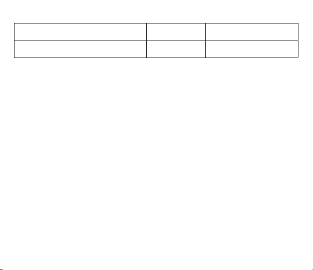
Table 1 continued
NMEA 2000 PGN NMEA 0183
129810 AIS Class B «CS» Static Data Report,
Part B
Note (1): Air, dew point, inside (saloon), water and exhaust gas temperature, inside and outside
humidity, barometric pressure are supported.
Note (2): Only messages with data instance 0 are converted.
Note (3): Device with factory settings perform conversion from true to apparent wind
and vice versa. MWV sentence is sending twice (one for relative wind and one for true).
See VII.4 (SET command) for details.
Note (4): Magnetic variation is used in RMC, HDT, HDG, VDR, VHW, VTG. Priority of variation
PGNs: 127250, 127258, 65311.
Note (5): MDA is sent only when air, dew point or water temperature, or barometric pressure or
outside humidity are available. Also contains wind speed and direction.
Note (6): DIN and PGN are wrap NMEA 2000 messages according SeaSmart (v1.6.0) and MiniPlex
(v2.0) specications. Engine revolutions, boost pressure, coolant temperature, hours,
fuel rate, alternator voltage are also transmitted in XDR sentence.
Sentence
VDM, VDO AIS VHF message 24
— 51 —
Comment
Page 52
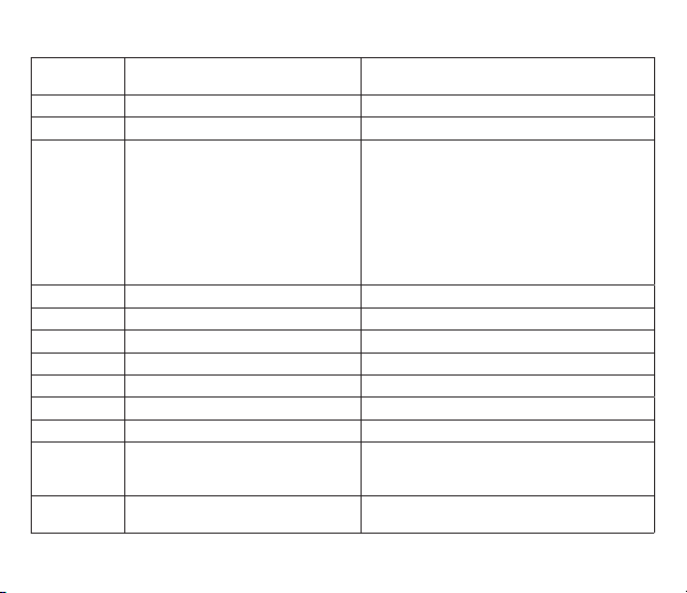
Table 2. Conversions from NMEA 0183 to NMEA 2000
NMEA 0183
Sentence
NMEA 2000 PGN Comment
APB 129283 Cross Track Error Also used in PGN 129284
DPT 128267 Water Depth
DIN 59904 ISO Request
127488 Engine Parameters, Rapid
Update
127489 Engine Parameters, Dynamic
127493 Transmission Parameters,
Dynamic
127502 Switch Bank Control
127505 Fluid Level
127508 Battery Status
According SeaSmart.Net protocol specication
v1.6.0
DTM 129044 Datum
GGA 129029 GNSS Position Data ZDA or RMC are required
GLL 129025 Position, Rapid Update See note (7)
GSA 129539 GNSS DOPs
GSV 129540 GNSS Sats in View Use data from GRS and GSA
HDG 127250 Vessel Heading
HDM, HDT 127250 Vessel Heading Use variation and deviation from HDG
MDA 130311 Environmental Parameters
MOB 127233 Man Overboard Notication
130314 Actual Pressure
130306 Wind Data
(MOB)
Relative air humidity, air and water
temperature, atmospheric pressure, wind data
— 52 —
Page 53
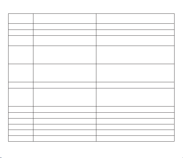
Table 2 continued
NMEA 0183
Sentence
NMEA 2000 PGN Comment
MTW 130311 Environmental Parameters
MWD 130306 Wind Data
MWV 130306 Wind Data Theoretical wind sent as calculated using
RMB 129283 Cross Track Error
RMC 126992 System Time
129284 Navigation Data
129285 Navigation —
Route/WP information
127258 Magnetic Variation
129025 Position, Rapid Update
129026 COG & SOG, Rapid Update
Heading/Speed through Water
Use data from APB; PGN 129284 sent twice
with true and magnetic bearings
See note (7)
RSA 127245 Rudder
RTE 130066 Route and WP Service —
Route/WP-List Attributes
130067 Route and WP Service —
Route — WP Name & Position
Use data from WPL
ROT 127251 Rate of Turn
VBW 130578 Vessel Speed Components
VDR 129291 Set & Drift, Rapid Update
VHW 128259 Speed, Water referenced
VLW 128275 Distance Log
VTG 129026 COG & SOG, Rapid Update
— 53 —
Page 54
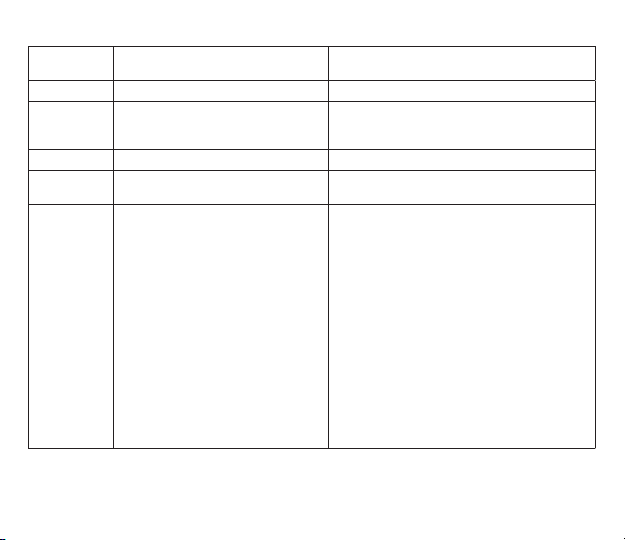
NMEA 0183
Sentence
NMEA 2000 PGN Comment
VWR, VWT 130306 Wind Data
WPL 130074 Route and WP Service —
WP List — WP Name &
Position
XTE 129283 Cross Track Error
ZDA 126992 System Time
VDO, VDM 129038 AIS Class A Position Report
129033 Local Time Offset
129039 AIS Class B Position Report
129040 AIS Class B Extended
Position Report
129041 AIS Aids to Navigation (AtoN)
Report
129793 AIS UTC and Date Report
129794 AIS Class A Static and Voyage
Related Data
129798 AIS SAR Aircraft Position
Report
129802 AIS Safety Related Broadcast
Message
129809 AIS Class B «CS» Static Data
Report, Part A
129810 AIS Class B «CS» Static Data
Report, Part B
— 54 —
Table 2 continued
Only waypoints not included to the route (the
RTE should be received during 3 seconds after
WPL).
AIS VHF messages 1, 2 and 3
AIS VHF message 18
AIS VHF message 19
AIS VHF message 21
AIS VHF messages 4 and 11
AIS VHF message 5
AIS VHF message 9
AIS VHF Message 14
AIS VHF message 24
AIS VHF message 24
Page 55

Note (7): The Device provides 50 milliseconds intervals between outgoing NMEA 2000 messages
that are generated by more than one NMEA 0183 sentence. For example, a message
with PGN 129025 is generated only once if RMC and GLL are received within
a 50 millisecond interval, and twice if the time between GLL and RMC is more than
50 milliseconds.
Note (8): Sentences with no signicant data (or data marked as invalid) may not be translated
to NMEA 2000 messages. NMEA 0183 sentences with invalid check sum are ignored.
— 55 —
Page 56

APPENDIX E. Format of Messages in RAW Mode
In RAW mode, network messages are converted to plain text format. We recommend that software
developers support this format in applications because it is the easiest option. In the terminal window,
NMEA 2000 messages look like a log in a chart plotter.
Messages sent from Device to PC have the following form:
hh:mm:ss.ddd D msgid b0 b1 b2 b3 b4 b5 b6 b7<CR><LF>
where:
• hh:mm:sss.ddd — time of message transmission or reception, ddd are milliseconds;
• D — direction of the message (‘R’ — from NMEA 2000 to PC, ‘T’ — from PC to NMEA 2000);
• msgid — 29-bit message identier in hexadecimal format (contains NMEA 2000 PGN and other
elds);
• b0..b7 — message data bytes (from 1 to 8) in hexadecimal format;
• <CR><LF> — end of line symbols (carriage return and line feed, decimal 13 and 10).
Example:
17:33:21.107 R 19F51323 01 2F 30 70 00 2F 30 70
17:33:21.108 R 19F51323 02 00
17:33:21.141 R 09F80115 A0 7D E6 18 C0 05 FB D5
17:33:21.179 R 09FD0205 64 1E 01 C8 F1 FA FF FF
17:33:21.189 R 1DEFFF00 A0 0B E5 98 F1 08 02 02
17:33:21.190 R 1DEFFF00 A1 00 DF 83 00 00
17:33:21.219 R 15FD0734 FF 02 2B 75 A9 1A FF FF
Time of message is UTC time if the Device has received the time from the NMEA 2000 network, otherwise
it is the time from Device start.
The format of messages sent from application to Device is the same, but without time and direction eld.
— 56 —
Page 57

Outgoing messages must end with <CR><LF>. If the message from application is accepted, passes lters
and is transmitted to NMEA 2000, it will be sent back to the application with ‘T’ direction.
For example, the application sends the following sentence to the Device:
19F51323 01 02<CR><LF>
When this message is sent to the NMEA 2000 network, the Application receives an answer like:
17:33:21.108 T 19F51323 01 02<CR><LF>
The Application will get no answer if the message ltered or the message syntax is invalid.
The format of NMEA 2000 messages is available in Appendix B of NMEA 2000 Standard, which
can be purchased on the site www.nmea.org.
— 57 —
Page 58
APPENDIX F. Format of Messages in N2K Mode
In N2K mode, messages are encoded in a binary format. This format is based on Data Link Escape encoding
partially compatible with ActiSense NGT format and widely support by modern marine applications.
This format is very similar to Garmin Serial Protocol (see section 3.1 of Garmin Device Interface
Specication 001-00063-00 for details).
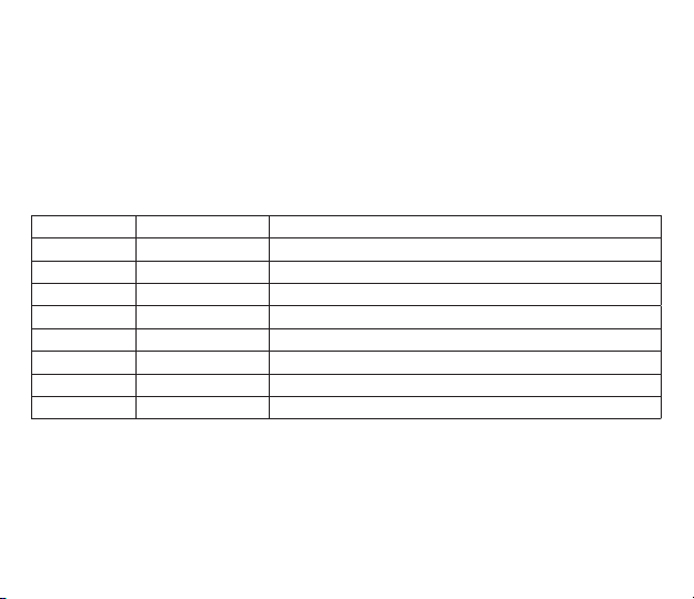
All data are transferred in byte-oriented packets. A packet contains a four-byte header (DLE, STX, ID,
and Size), followed by a variable number of data bytes, followed by a three-byte trailer (Checksum, DLE,
and ETX). The following table shows the format of a packet:
Byte Number Byte Description Note
0 Data Link Escape ASCII DLE character (16 decimal)
1 Start of Text ASCII STX character (02 decimal)
2 Packet ID Identies the type of packet
3 Size of Packet Data Number of bytes of packet data (bytes 4 to n-4)
4 to n—4 Packet Data 0 to 255 bytes, see Table 2
n—3 Checksum 2's complement of the sum of all bytes from byte 1 to byte n-4
n—2 Data Link Escape ASCII DLE character (16 decimal)
n—1 End of Text ASCII ETX character (03 decimal)
If any byte in the Size, Packet Data, or Checksum elds is equal to DLE, then a second DLE is inserted
immediately following the byte. This extra DLE is not included in the size or checksum calculation.
This procedure allows the DLE character to be used to delimit the boundaries of a packet.
Packets with NMEA 2000 messages transmitted to the PC application (incoming) have ID 0x93
(147 decimal), packets with NMEA 2000 messages sent by the application to the Device (outgoing)
have ID 0x94 (148 decimal).
— 58 —
Table 1. Packet format
Page 59
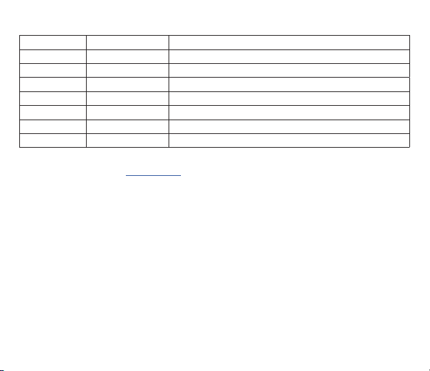
Table 2. Packet data format
Byte Number Byte Description Note
0 Message Priority Bits 0 - 2 are signicant, other bits are ignored
1 to 3 NMEA 2000 PGN Least signicant byte is rst
4 Destination Address Or 255 decimal for global addressed messages
5 Source Address Ignored for outgoing messages, Device address is used
6—9 Time Stamp Device’s time in milliseconds, ignored in outgoing messages
10 Size of Payload Number of bytes in NMEA 2000 message payload (1..232)
11+ Message Payload 1 to 232 bytes of message payload
The format of NMEA 2000 messages is available in Appendix B of NMEA 2000 Standard, which
can be purchased on the site www.nmea.org.
— 59 —
Page 60

 Loading...