

Page 1
XG2
User Manual
USM Ver 1.3
Page 2
Foreword
Copyright
Copyright © 2011 Xtramus Technologies, all rights reserved. The information contained in this document is the property of Xtramus
Technologies. No part of this publication shall be reproduced, stored in a retrieval system, or transmitted, in any form or by any
means, without the prior written permission of Xtramus Technologies.
Disclaimer
The information contained in this document is subject to change without notice and does not represent a commitment on the part of
Xtramus Technologies. The information in this document is believed to be accurate and reliable. However, Xtramus Technologies
assumes no responsibility or liability for any errors or inaccuracies that may appear in the docume nt.
Trademarks
XG2 is a trademark or registered trademark of Xtramus Technologies. All other trademarks and registered trademarks are the
property of their respective owners.
Warranty
Xtramus Technologies warrants for the hardware provided al ong with this document under proper usage and conditions in normal
environment; any improper operation or in irregular environment may possibly cause this product NOT function well. For detailed
terms, please contact your local dealer.
Contact Information
Xtramus Technologies
E-mail: sales@xtramus.com
Website: www. xtramus.com
Tel: +886-2-8227-6611
Fax: +886-2-8227-6622
XTRAMUS TECHNOLOGIES®
2
E-mail: sales@xtramus.com
Website: www.Xtramus.com
Page 3
Revision History
FW
Date
Feb, 2009 1.0.
April, 2010 1.1.
August, 2010 1.2.
2011/01/10 1.3
Versi
on
FPGA
Version
USM
History
Version
First version
Second version, changing XG2 overview/feature based on
latest PBF, adding XG2 series specification table, changing
chapter arrangements, and deleting Chapter 4
“Maintenance”.
Updating XG2 console interface.
Change the Foreword on page 2.
XTRAMUS TECHNOLOGIES®
3
E-mail: sales@xtramus.com
Website: www.Xtramus.com
Page 4

Table of Contents
Foreword..........................................................................................................................................2
Revision History..............................................................................................................................3
1. XG2 Overview ..............................................................................................................................5
1.1. General Description of XG2...............................................................................................5
1.2. Key Features of XG2 ..........................................................................................................5
1.3. XG2 Series Outer Case/Interface Overview .....................................................................6
2. XG2 Installation .........................................................................................................................11
2.1. Choice of UTP Cable and Optical fiber...........................................................................11
2.1.1. 10GBASE-T (Copper Wire).......................................................................................... 11
2.1.2. 10GBASE-R (Optical Fiber).........................................................................................13
2.2. Connection of UTP Cable and Optical fiber...................................................................14
2.2.1. 10GBASE-T (Copper Wire)..........................................................................................14
2.2.2. 10GBASE-R (Optical Fiber).........................................................................................14
2.3. Application for your network...........................................................................................17
2.3.1. Application for University...........................................................................................17
2.3.2. Application for Online Game Company.....................................................................18
2.3.3. Application for Home User .........................................................................................19
3. Additional Function...................................................................................................................20
3.1. Loopback...........................................................................................................................20
3.2. Operation via Console Port .............................................................................................21
4. XG2 Specifications....................................................................................................................26
XTRAMUS TECHNOLOGIES®
4
E-mail: sales@xtramus.com
Website: www.Xtramus.com
Page 5
1. XG2 Overview
1.1. General Description of XG2
XG2 Series are high-performance 10G media converters for connecting dif f erent
10G devices and link. XG2 Series functions as a copper-to-fiber
converter, a fiber mode converter, or a fib er repeater. Five interface of
XG2 series are available and supported: RJ45 to SFP+, SFP+ to SFP+,
SFP+ to XFP, RJ45 to XFP, and CX4 to SFP+.
All XG2 Series are equipped with real-time LEDs which display the status of each
port. The built-in loopback functions make XG2 Series ideal for troubleshooting by sending
packets like BERT patterns to network equipment.
For example, as a media converter, XG2 provides a bi-directionally conversion between 10GBASE-R (fiber) and
10GBASE-T (copper). If the ISP administrator would like to deploy FTTX services from central office to the user’s
street or large organization building by fiber as the last mile connection, XG2 could conve rt the media type from fiber
to copper wire, and then distribute to any nearby location with 10Gbps Ethernet switch, or to xDSL modem via
DSLAM.
XG2 could also act as an auxiliary device for testing 10GBASE-T/ 10GBASE-R equipments by connecting
NuStreams 10Gbps Ethernet fiber modules such as XM-28L1 and XM-28L1CX 4.
With various interfaces, XG2 Series provide different conversions betwee n fibers and copper wires in 10Gbps
Ethernet.
1.2. Key Features of XG2
• Real-Time conversion between 10GBASE-T, 10GBASE-R, and 10GBASE-CX4
¾ Interface of 10GBASE-T based on IEEE 802.3an
¾ Interface of 10GBASE-R based on IEEE802.3ae
¾ Interface of 10GBASE-CX4 based on IEEE 802.3ak
• Conversion of media type between fiber (SFP+, XFP) and twisted pair copper wire (RJ-45, CX4)
• Real-time LEDs that display running status
¾ SFP+ status: Indicate the SFP+ fiber connector is connected or not
¾ LR status: Indicate the LR Transceiver or SR transce iver is plugged or not
¾ Link/Rx status: Display the Network linked/Receive status
¾ SFP+/Rx status: Di splay the Network linked/Receive status (For XG2-1 only)
¾ Loopback status: Indicate the Loopback test status of A and B ports
¾ SYS status: Indicate system operation status
• Console for updating firmware and configuring loopback functions
• Both SFP+ and RJ-45 port can connect to other 10Gbps Ethernet switch for expansi on.
• Subsidiary device for test on 10Gbps Ethernet switch with 10GBASE-T and/or 10GBASE-R ports
XTRAMUS TECHNOLOGIES®
5
E-mail: sales@xtramus.com
Website: www.Xtramus.com
Page 6
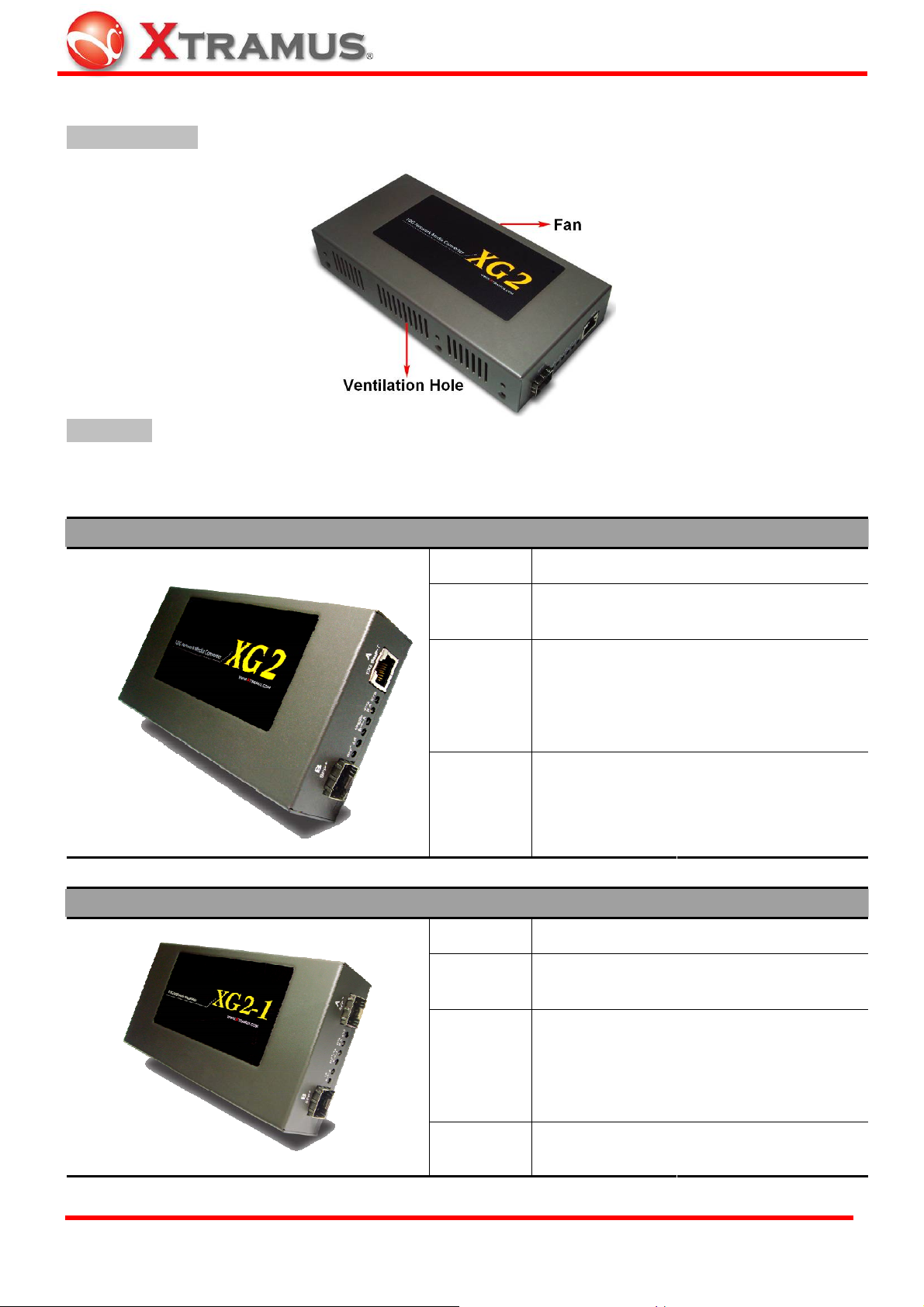
1.3. XG2 Series Outer Case/Interface Overview
Front & Rear Side
Right Panel
XG2’s right panel contains its interface ports and information LEDs. The type of XG2’s interface ports and LED
displays are different among XG2, XG2-1, XG2-2, XG2-3, and XG2-4.
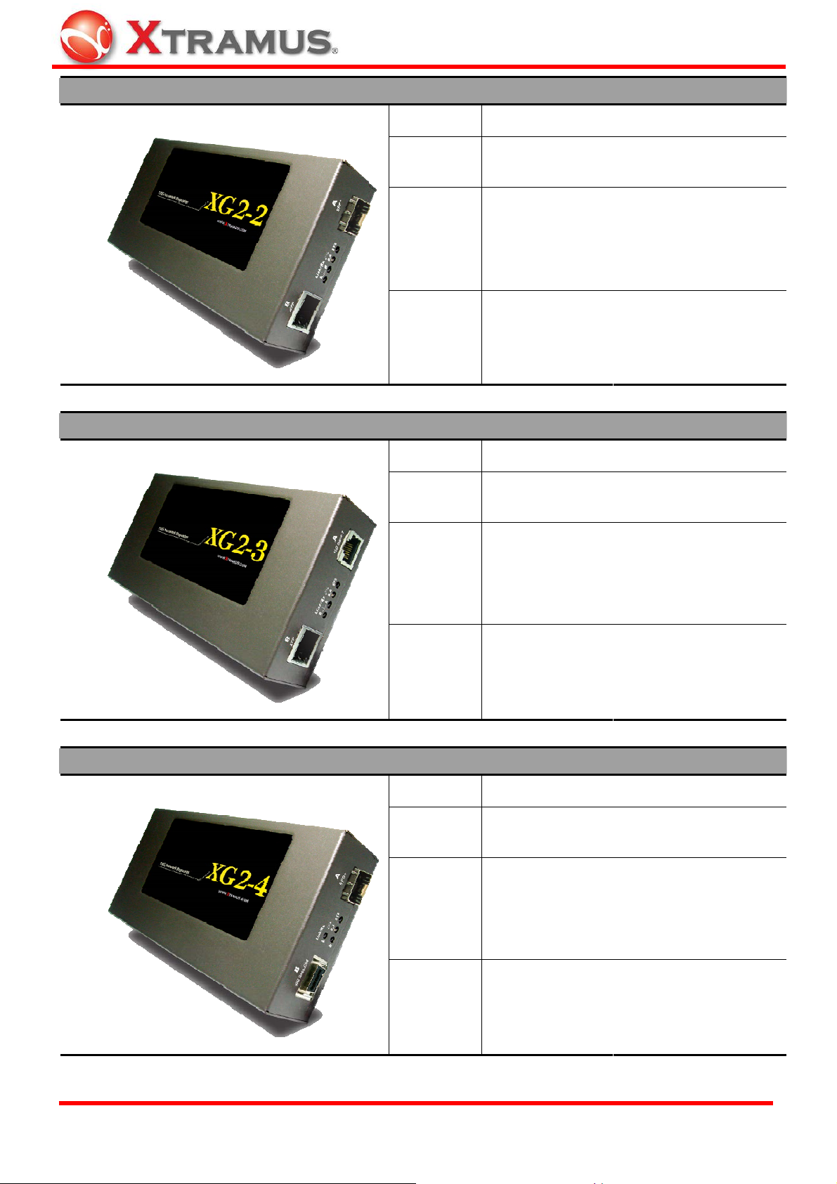
XG2
XG2-1
Interface
Protocol
Fixed Port
LED Display
Interface
Protocol
Port A
Port B
Port A
Port B
RJ45 to/from SFP+
IEEE802.3an (10GBase-T)
IEEE802.3ae (10GBase-R)
One 10Gbps UTP Port
One 10Gbps SFP+ Port
One RS-232 Console Port
One Power Jack
SFP+
Link/Rx A
Link/Rx B
SFP+ to/from SFP+
IEEE802.3ae (10GBase-R)
IEEE802.3ae (10GBase-R)
LR
Loopback
SYS
XTRAMUS TECHNOLOGIES®
Fixed Port
LED Display
6
Two 10Gbps SFP+ Port
One RS-232 Console Port
One Power Jack
LR A
LR B
SFP+/Rx A
SFP+/Rx B
SYS
E-mail: sales@xtramus.com
Website: www.Xtramus.com
Loopback
Page 7
XG2-2
XG2-3
Interface
Protocol
Fixed Port
LED Display
Interface
Protocol
Port A
Port B
Port A
Port B
SFP+ to/from XFP
IEEE802.3ae (10GBase-R)
IEEE802.3ae (10GBase-R)
One 10Gbps SFP+ Port
One 10Gbps XFP Port
One RS-232 Console Port
One Power Jack
Link/Rx A
Link/Rx B
RJ45 to/from XFP
IEEE802.3an (10GBase-T)
IEEE802.3ae (10GBase-R)
Loopback
SYS
XG2-4
Fixed Port
LED Display
Interface
Protocol
Fixed Port
Port A
Port B
One 10Gbps UTP Port
One 10Gbps XFP Port
One RS-232 Console Port
One Power Jack
Link/Rx A
Link/Rx B
CX4 to/from SFP+
IEEE802.3ae (10GBase-CX4)
IEEE802.3ae (10GBase-R)
One 10Gbps SFP+ Port
One 10Gbps CX4 Port
One RS-232 Console Port
Loopback
SYS
XTRAMUS TECHNOLOGIES®
LED Display
7
Link/Rx A
Link/Rx B
One Power Jack
Loopback
SYS
E-mail: sales@xtramus.com
Website: www.Xtramus.com
Page 8
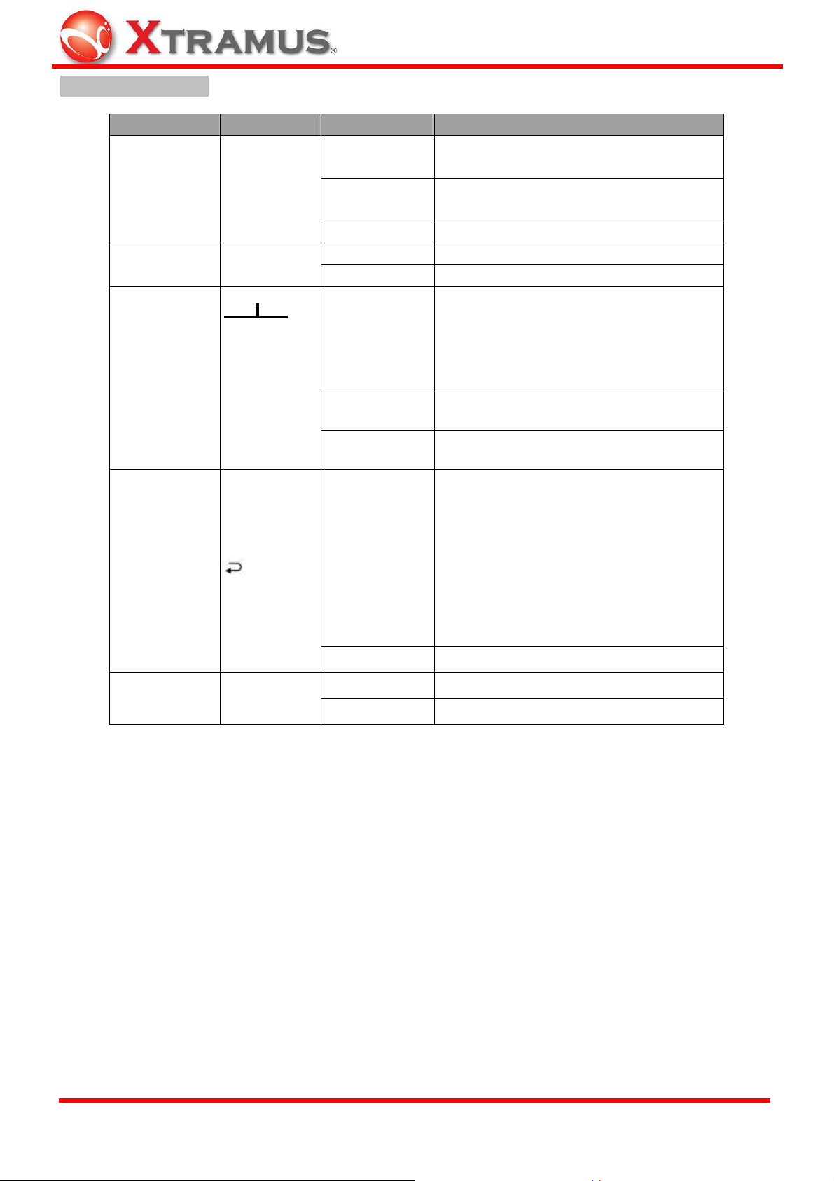
XG2-5
Interface
Port A
XFP to/from XFP
IEEE802.3ae (10GBase-R)
Protocol
Port B
IEEE802.3ae (10GBase-R)
Two 10Gbps XFP Ports
Fixed Port
One RS-232 Console Port
One Power Jack
LED Display
Link/Rx A
Link/Rx B
Loopback
SYS
Please note that for network flow conversion, the media speed of two ends has to be symmetrical; otherwise, packet
loss happens during conversion. Hence, the connection speed of copper UTP port A must be 10Gbps connection,
for the conversion of 10Gbps SFP+ connection. 10M/100M/1000Mbps UTP connection is not applicable to XG2.
XTRAMUS TECHNOLOGIES®
8
E-mail: sales@xtramus.com
Website: www.Xtramus.com
Page 9
XG2 Right Panel LEDs
Type Label LED Description
Fiber Connector
(Transceiver)
Status
Mode
Connection
Status
SFP+
LR (*Note 1)
Link/ACT
A B
Amber
Green
Remind user that the SFP+ form factor
transceiver (connector) is connected.
Transceiver (connector) with powered optical
fiber is connected.
OFF No SFP+ transceiver (connector) is plugged.
Green Connector of LR Transceiver is plugged. 10BASE-R
Amber Connector of SR Tra nsceiver is plugged.
Display the Network linked/Active status.
ON at Port A: connection o f network cable at
ON (Green)
port A is linked.
ON at Port B: connection of optical fiber at
port B is linked.
OFF
No connection
Blinking
Data is receiving.
Loopback mode of A and B ports is enabled.
Loopback test is the method to send out signal
and quickly back to the same source entity to
Loopback Test
Status
(A + B )
ON (Green)
test the transmission and route problem of
infrastructure. When loopback is enabled,
XG2 returns incoming data flow back to
original entity.
OFF
Blinking Green
Loopback test is disabled.
Status of system operation. System is ready.
System Status SYS
Amber
System is starting.
XTRAMUS TECHNOLOGIES®
9
E-mail: sales@xtramus.com
Website: www.Xtramus.com
Page 10

XG2 Left Panel
Connection Ports
9 pin RS-232
Console
Power Socket 12V DC
LED Status
Power Status Power LED is ON when power jack of adapter is plugged.
Type Label Description
38400, n, 8, 1 Control of Loopback test and other application
Plug power from DC 12V adapter.
Note: XG2 media converter has to convert and transmit data
flow for both copper and fiber connection that has larger power
consumption. Please do use the power adapter that comes
with XG2 to prevent damage.
Type Label Description
XTRAMUS TECHNOLOGIES®
10
E-mail: sales@xtramus.com
Website: www.Xtramus.com
Page 11

2. XG2 Installation
XG2 is an equipment that administrator only has to plug fiber/cable and then it works, as easy as general Ethernet
switch without extra configuration. Hence, the most important things are not the operation of XG2. The configuration
of cabling, selections of physical media and applications in your environment is more important.
2.1. Choice of UTP Cable and Optical fiber
2.1.1. 10GBASE-T (Copper Wire)
10GBASE-T, or IEEE 802.3an-2006, is a standard released in 2006 to provide 10 gigabit/second connections over
unshielded or shielded twisted pair cables, over distances up to 100 meters (330 ft). 10GBASE-T cable
infrastructure can also be used for 1000BASE-T, allowing a gradual upgrade from 1000BASE-T, and
auto-negotiation to select which speed to use.
Connectors
10GBASE-T uses 650 MHz versions of the venerable IEC 60603-7 8P8C (RJ-45) connectors, that is already
widely used in Ethernet.
Cables
10GBASE-T works up to 55 m (180 ft) with existing Category 6 cabling. In order to allow deployment at the usual
100 m (330 ft), the standard uses a new partitioned Category 6a cable specification, designed to reduce crosst alk
between UTP cables.
Category of UTP network cable for reference
Cat 5
Provides performance of up to 100 MHz, and was frequently used on 100 Mbps Ethernet networks. May be
unsuitable for 1000BASE-T gigabit Ethernet.
Cat 5e
Provides performance of up to 100 MHz, and is frequently used for both 100 Mbit/s and Gigabit Ethernet networks.
Cat 6
Provides performance of up to 250 MHz, more than double of category 5 and 5e. It works up to 55 m (180 ft) for
10Gbps Ethernet.
Cat 6a
Provides performance of up to 500 MHz, double of category 6. It is suitable for 10GBASE-T. It works up to 100 m
(330 ft) for 10Gbps Ethernet. All the cables above does not have individually-shielded pairs as the picture below,
including Cat 6a.
XTRAMUS TECHNOLOGIES®
11
E-mail: sales@xtramus.com
Website: www.Xtramus.com
Page 12

Cat 7
This standard specifies four individually-shielded pairs (STP ) inside an overall shield. Designed for transmission at
frequencies up to 600 MHz. It has better performance than Cat 6a.
XTRAMUS TECHNOLOGIES®
12
E-mail: sales@xtramus.com
Website: www.Xtramus.com
Page 13

2.1.2. 10GBASE-R (Optical Fiber)
10GBASE-R is 10Gbps Ethernet connection that based on IEEE802.3ae. It uses fiber as transmission media with
different specification of fiber, connector and transceiver. XG2 uses two standards, 10GBASE-LR and
10GBASE-SR.
10GBASE-SR
10GBASE-SR ("short range") uses 64B/66B encoding and 850 nm wavelength lasers. It is designed to support
short distances over deployed multi-mode fiber cabling, it has a range of between 26 meters (85 ft) and 82 meters
(270 ft) depending on cable type. It also supports 300 meters (980 ft) operation over new, 50 μm 2000 MHz•km
OM3 multi-mode fiber (MMF).
The transmitter can be implemented with a VCSEL (Vertical Cavity Surface Emitting Laser) which is low cost and
low power. MMF has the advantage of having lower cost connectors than SMF (single-mode fiber) due to its wider
core.
10GBASE-SR delivers the lowest cost, lowest power and smallest form factor optical modules.
10GBASE-LR
10GBASE-LR ("long range") is a Long Range Optical technology delivering serialized 10 gigabit Ethernet over a
laser with 1310 nm wavelength connection on single-mode fiber via IEEE 802.3 Clause 49 64B-66B Physical
Coding Sub layer (PCS) using a line rate of 10.3125.
Single-mode optical cabling is used to interconnect transceivers at a dist an ce spaced at 10 kilometers (6.2 mi), but
it can often reach distances of up to 25 kilometers (16 mi) with no data loss.
Fabry-Perot lasers are commonly used in 10GBASE-LR optical modules. Fabry-Perot lasers are more expensive
than VCSELs (mentioned above) but their high power and fo cused beam allow ef ficient coupling into the small core
of single mode fiber.
Fiber Specification
Fibers which support many propagation paths or transverse modes are called multi-mode fibers (MMF). Fibers
which can only support a single mode are called single-mode fibers (SMF). Multi-mode fibers generally have a
larger core diameter, and are used for short-distance communication links and for applications where high power
must be transmitted. Single-mode fibers are used for most communication links longer than 200 meters.
Fiber Buffer/Jacket color Meaning
Yellow Single-mode optical fiber, long distance connection
Orange Multi-mode optical fiber, short distance connection
XTRAMUS TECHNOLOGIES®
13
E-mail: sales@xtramus.com
Website: www.Xtramus.com
Page 14

2.2. Connection of UTP Cable and Optical fiber
2.2.1. 10GBASE-T (Copper Wire)
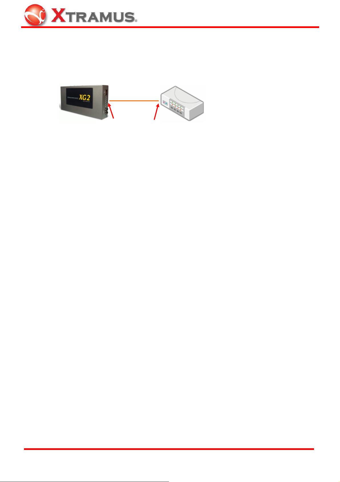
10GBASE-T uses the same RJ-45 connector that is the same as original 100M/1000Mbps Ethernet network. Plug
the RJ-45 connector into the port of 10Gbps, then it is ready to work.
Watch the LED statu s of Li nk/ACT of port A to know t he connection status.
RJ-45 Connector
Plug into
2.2.2. 10GBASE-R (Optical Fiber)
The connection of optical fiber can be departed to 4 sections
LR or SR Mode
Transceiver
SFP+ Transceiver
Fiber Connector
Plug into
Connect
Cat. 6, Cat. 6a UTP Cable
Optical Fiber
Connect
Optical Fiber:
As the description above, there are Single-mode and Multi-mode optical fiber. Both of them can be used for XG2
Fiber Connector:
Unlike RJ-45 connector, the fiber can be removed from SFP+ transceiver easily. At two ends of fiber, it has
connector that can attach to SFP+ transceiver. There are two fibers for one SFP+ transceiver. One fiber is for
receiving and one fiber is for transmission. The pict ure below is called LC connector that can attach to SFP+
transceiver.
XTRAMUS TECHNOLOGIES®
14
E-mail: sales@xtramus.com
Website: www.Xtramus.com
Page 15

Transceiver (Connector):
SFP+ Transceiver is the hardware that is pluggable into the body of XG2. Unlike RJ-45 connector that there is no
component inside at all, SFP+ Tra nsceiver is an active component that consumes power from XG2 and it has the
key function that convert signals between optical data flow and electronic data flow.
A
B C D
E
For different transmission purpose, the component inside SFP+ form factor can be 10BASE-LR or 10BAST-SR
mode.
When SFP+ transceiver is plugged into the XG2, the LED of SFP+ is Amber. If the inserted SFP+ transceiver is
attached by a fiber with LC connector with going on signaling, the LED becomes Gree n. The LED of LR is either
Green for 10BASE-LR mode or Amber for 10BASE-SR mode. Details are shown at the table below:
LED Status
Type Label LED Description
Fiber Connector
(Transceiver)
Status
Mode
SFP+
LR
A: Handgrip to remove module from XG2 easily
B: Connection from LC fiber connector that is described above
C: Bottom of the transceiver module
D: Electronic conductor to XG2 body
E: Size of matchstick.
Amber Remind user that the SFP+ form factor
transceiver (connector) is connected.
Green Transceiver (connector) with powered
optical fiber is connected.
OFF No SFP+ transceiver (connector) is
plugged.
Green Connector of LR Transceiver is plugged. 10BASE-R
Amber Connector of SR Transceiver is plugge d.
SFP+ LED LR LED Description
(Amber)
(Amber)
(Green)
(Green)
XTRAMUS TECHNOLOGIES®
(Green)
(Amber)
(Green)
(Amber)
No SFP+ form factor transceiver (connector) is plugged.
LR mode SFP+ form factor transceiver (connector) is plugged. No
powered fiber is connected
SR mode SFP+ form factor transceiver (connector) is plugged. No
powered fiber is connected
LR mode SFP+ form factor transceiver (connector) is plugged.
Powerd fiber is connected
SR mode SFP+ form factor transceiver (connector) is plugged.
Powerd fiber is connected
15
E-mail: sales@xtramus.com
Website: www.Xtramus.com
Page 16
The size and specification of transceiver are independent from the Ethernet protocol transmitted and received
inside fiber.
Hence, there is no problem for the fiber connection between XG2's SFP+ transceiver (connector) a nd XFP
transceiver (connector) that is plugged at other device.
Fiber
Other 10Gbps
Device
SFP+ Transceiver
XFP Transceiver
Note: SFP+ Transceiver that complies with 10GBASE-LR/SR standard is suitable for XG2. Fo r recommended
SFP+ Transceiver, please contact with distributor.
XTRAMUS TECHNOLOGIES®
16
E-mail: sales@xtramus.com
Website: www.Xtramus.com
Page 17
2.3. Application for your network
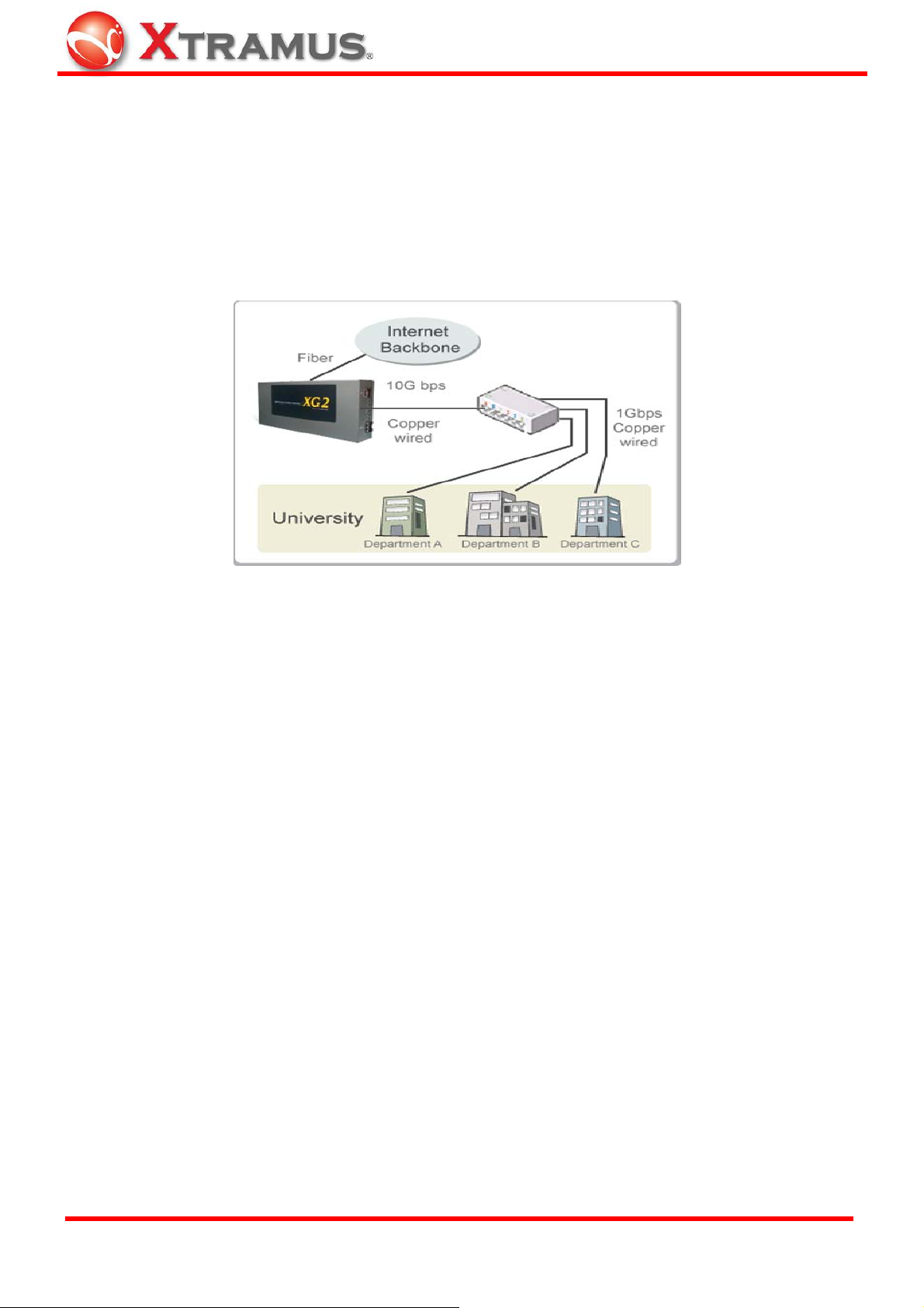
2.3.1. Application for University
10Gbps speed Ethernet connection may not be common seen in the office; however, administrator may has
Gigabit Ethernet in the control room of office already. Get a 10Gbps Ethernet connection from backbone and
distribute it to different Gigabit Ethernet segment for different building or organization is practical and more
cost-effective. Here is an example of possible plan.
A
B
C D E
F
G H I
This example is a possible network structure of a university.
A: Internet backbone from ISP.
B: The distance from the central office to the university might be long, so construct the connection via single-mode
optical fiber with 10BASE-LR mode, which can extend the distance beyond several tenth of kilometer.
C: XG2 is located at the computer center of university.
D: After the conversion of XG2, expensive equipment for transmitting/receiving network data via optical fiber is not
required afterward.
E: Full 10Gbps Ethernet Switch may beyond your budget or it is not available. Some 1Gbps Switch reserves a
swappable slot for the upgrade of future technology. Plug a 10Gbps module with one 10Gbps port to this kind of
Switch is enough for this application.
F: After the distribution of 1Gbps Ethernet Switch with attached 10Gbps module, several 1Gbps conn ections can
be distributed to different buildings inside the university by Cat. 6a network cable, which can be extended to 100
meters.
G, H, I: Different buildings or departments in one building. General switch with 1Gbps and 1 00Mbps ports can be
connected here for end-user.
XTRAMUS TECHNOLOGIES®
17
E-mail: sales@xtramus.com
Website: www.Xtramus.com
Page 18

2.3.2. Application for Online Game Company
For ISP or online game company, XG2 may also save lots of money for cabling their control room. ISP runs lots of
customer's service such as e-mail server, web server or any co-located network services in the control room.
These equipments may not have interface for the connection of optical fiber. For online game company,
administrator may have lots of online game servers that need high-speed connection to Internet backbone in the
control room.
A
B
C
D E
F
G
H
I
A: Client users from Internet
B: For the mass requests from general public. The main requests come from other ISP in Internet.
C: The distance from the other ISP to the game company might be long, so construct the connection via
single-mode optical fiber with 10BASE-LR mode, which can extend the distance beyond several tenth of kilometer.
D: XG2 is located at the control room of the game company.
E: After the conversion of XG2, transceiver and equipment of optical fiber is not required in the control room
afterward.
F: Depending on the requirement of loading, Ethernet Switch with full 10Gbps ports or partial 10Gbps/1Gbps ports
is configured for the distribution of data flow.
G: Assume that the bandwidth requirement of co-located mail servers for some companies is not heavy; connect
them to 1Gbps port of 10Gbps switch.
H: Assume that the bandwidth requirement of online game servers is heavy; connect them to 10Gbps port of
10Gbps switch.
l: Different kinds of server with different applications are lo cated side by side by connection s from 10Gbps Ethernet
Switch via inexpensive Cat.6 cable.
XTRAMUS TECHNOLOGIES®
18
E-mail: sales@xtramus.com
Website: www.Xtramus.com
Page 19

2.3.3. Application for Home User
A schematic illustrating how the FTTX architectures vary with regard to the distance betwe en the optical fiber and
the end-user. Fiber to the x (FTTX) is a generic term for any network architecture that uses optical fiber to replace
all or part of the usual copper local loop used for telecommunications. The four technologies, in order of an
increasingly longer fiber loop are:
Fiber to the node / neighborhood (FTTN)
¾
¾ Fiber to the curb (FTTC) / Fiber to the kerb (FTTK)
¾ Fiber to the building (FTTB)
¾ Fiber to the home (FTTH)
E
A B C D
F
The building on the left is the central office; the building on the righ t is one of the buildings served by the central
office. The white or gray blocks represent separate rooms or office spaces within the same building.
A: Central Office of ISP
B: Network connection via optical fiber
C: Installation of XG2 for media conversion
D: Network connection via copper wire. It can be Cat. 6a cable (under 300 meters) or telephone line via xDSL
(Technologies such as VDSL provide high speed, short-range link are used often in FTTx service)
E: Different rooms of home or different com partments in the same building.
F: XG2 can be located at any place that near or away from building, depending on the service to home users.
Advantage for ISP
For the time before, if the client has requirement of lots bandwidth, ISP has to cabling several fibers with gigabit
connection to the same location and distributes the connection by Gigabit switch or media converter to copper
wired destination.
Depends on the bandwidth required for client, ISP can configure a XG2 medi a converter between the conn ection of
light blue and dark blue line in the graph. With 10G Ethernet conversion between fiber and copper wire, ISP can
provide heavyweight bandwidth service that is closer to the client without spending too much cost.
XTRAMUS TECHNOLOGIES®
19
E-mail: sales@xtramus.com
Website: www.Xtramus.com
Page 20

3. Additional Function
3.1. Loopback
XG2 has loopback function for the trouble shooting of network. Loopback test is the method to send out signal and
quickly back to the same source entity to test the transmission and route problem of infrastructure. Test equipment
with this troubleshooting technique sends specific patterns, and co unts any errors that come back (BERT,
Rate Test
test equipment to the XG2 flows returns to their source entity.
Here it illustrates how loopback works.
). From the operation of console port, user can active loopback test. When it is enabled, data stream from
D C
A B
D
E
B
Bit Error
A: XG2 that loopback function is enable for other test equipment or network infrastructure.
B: Signal with test patterns such as BERT is sent.
D: Signal with test patterns is back to original entity (test equipment).
C: Network equipment or test equipment with 10GBASE-T port that is able to send test patterns with destination of
itself via XG2
E: Network equipment or test equipment with 10GBASE-R port that is able to send test patterns with destination of
itself via XG2
XTRAMUS TECHNOLOGIES®
20
E-mail: sales@xtramus.com
Website: www.Xtramus.com
Page 21

3.2. Operation via Console Port
After connecting the COM port of PC to Console port of XG2 via Console cable, power on the PC and configure the
PC parameters as following path of Windows (by using Windows Hyper Terminal software):
Start Æ All programs Æ Accessories Æ Communications Æ Hyper Terminal
1. Input a name for this connection, such as XG2, and also select
an icon for this connection.
2. Select the COM port of PC for this connection. Generally, it is
COM1.
3. Configure the parameter of COM port as below, 38400, 8,
None, 1, None
XTRAMUS TECHNOLOGIES®
21
E-mail: sales@xtramus.com
Website: www.Xtramus.com
Page 22

Press "Enter" key to build connection and system enter into the main windows of XG2 Console Program
You can view XG2 system information, switching XG2 modes, or upgrading XG2 firmware with XG2 Console
Program.
XG2 system information is displayed in A. Information displayed here includes: Line Loopback Mode, SL/SGL
Mode, RJ45 Cable Length, 100GBase-T Pair Polarity, SFP+ Module Vender Name, SFP+ Module Vender
PN, SFP+ Module Laser Wavelength, and Temperature.
Also, you can key in numbers/characters listed in B with your keyboard to input commands for XG2.
<1> Change Line Loopback Mode
↑↓
You can enable/disable line loop back by pressing 1 on your keyboard. For
more information, please refer to 3.1. Loopback.
<2> Change SL/SGL Mode
You can switch the SL/SGL Mode by pressing 2 on your keyboard. SL
↑↓
Mode stands for Slave Link Mode, while SGL Mode stands for Segment
Mode. Two XG2s can’t be joined if they are both under Slave Link Mode.
XTRAMUS TECHNOLOGIES®
22
E-mail: sales@xtramus.com
Website: www.Xtramus.com
Page 23

<S> System Information
By pressing S on your keyboard, you can view detail XG2 information. To
exit System Information, please press any key on your keyboard.
<R> Refresh
To refresh all the information listed on XG2 Console Program, press R on your keyboard.
<U> Update Firmware
To update XG2 firmware, press U on your keyboard, and follow the steps down below:
1. Press U on your keyboard. System will ask if you want to update Firmware. Please press Y on your
keyboard.
2. XG2 Console Program will start the process required for updating firmware.
XTRAMUS TECHNOLOGIES®
23
E-mail: sales@xtramus.com
Website: www.Xtramus.com
Page 24

3. Please select Transfer → Send File on HyperTerminal’s menu bar.
4. A Send File window will pop up. Please set the Protocol to Xmodem, click Browse… button to
choose the XG2 firmware you would like to update, and click Open.
XTRAMUS TECHNOLOGIES®
24
E-mail: sales@xtramus.com
Website: www.Xtramus.com
Page 25

5. Click Send button on the Send File pop-up window to start sending firmware to XG2.
6. XG2 will reboot when finishing updating its firmware.
XTRAMUS TECHNOLOGIES®
25
E-mail: sales@xtramus.com
Website: www.Xtramus.com
Page 26

4. XG2 Specifications
XG2 Series Common Specifications
Type
Converter
Data Transfer Rate
Connectivity
Platform
Dimensions
Temperature
Humidity
• Operating: 0°C~ 40°C (32°F~ 104°F) • Storage: 0°C~ 50°C (32°F~ 122°F)
• Operating: 0% ~ 85% RH • Storage: 0% ~ 85% RH
Maximum Packet
Forwarding Rate
(packet per second)
XG2 Series Detailed Specifications
XG2
XG2-1
10Gbps
Wired
PC
LED Display
Interface
Protocol
Fixed Port
Management Port
Plug & Play
Standalone
Dimensions 175 x85.9x32.6mm (L x W x H)
175 x85.9x32.6mm (L x W x H)
14,880,950
RJ45 to/from SFP+
Port A
Port B
IEEE802.3an (10GBase-T)
IEEE802.3ae (10GBase-R)
10Gbps UTP Port×1 10Gbps SFP+ Port×1
RS-232 Console Port×1 Power Jack × 1
¾ SFP+
¾ LR
Serial Port
¾ Link/Rx A
¾ Link/Rx B
Yes
Yes
¾ Loopback
¾ SYS
XG2-2
Interface
Port A
SFP+ to/from SFP+
IEEE802.3ae (10GBase-R)
Protocol
Port B
IEEE802.3ae (10GBase-R)
10Gbps SFP+ Port × 2
Fixed Port
RS-232 Console Port×1 Power Jack × 1
LED Display
¾ LR A
¾ LR B
Interface
Port A
¾ SFP+/Rx A
¾ SFP+/Rx B
¾ Loopback
¾ SYS
SFP+ to/from XFP
IEEE802.3ae (10GBase-R)
Protocol
Port B
IEEE802.3ae (10GBase-R)
10Gbps SFP+ Port×1 10Gbps XFP Port×1
Fixed Port
RS-232 Console Port×1 Power Jack × 1
LED Display
¾ SFP+
¾ LR
¾ Link/Rx A
¾ Link/Rx B
¾ Loopback
¾ SYS
XTRAMUS TECHNOLOGIES®
26
E-mail: sales@xtramus.com
Website: www.Xtramus.com
Page 27

XG2-3
XG2-4
XG2-5
Interface
Port A
RJ45 to/from XFP
IEEE802.3an (10GBase-T)
Protocol
Port B
IEEE802.3ae (10GBase-R)
10Gbps UTP Port×1 10Gbps XFP Port×1
Fixed Port
RS-232 Console Port×1 Power Jack × 1
LED Display
Interface
¾ Link/Rx A
¾ Link/Rx B
Port A
CX4 to/from SFP+
IEEE802.3ae (10GBase-CX4)
¾ Loopback
¾ SYS
Protocol
Port B
IEEE802.3ae (10GBase-R)
10Gbps SFP+ Port×1 10Gbps CX4 Port×1
Fixed Port
RS-232 Console Port×1 Power Jack × 1
LED Display
Interface
¾ Link/Rx A
¾ Link/Rx B
XFP to/from XFP
¾ Loopback
¾ SYS
Port A
IEEE802.3ae (10GBase-R)
Protocol
Port B
IEEE802.3ae (10GBase-R)
10Gbps XFP Port × 2
Fixed Port
RS-232 Console Port×1 Power Jack × 1
LED Display
¾ Link/Rx A
¾ Link/Rx B
¾ Loopback
¾ SYS
XTRAMUS TECHNOLOGIES®
27
E-mail: sales@xtramus.com
Website: www.Xtramus.com
 Loading...