

Page 1

NuApps-POE
User’s Manual
USM V1.1
Page 2

2
E-Mail: sales@xtramus.com
Http://www.Xtramus.com
XTRAMUS TECHNOLOGIES®
Foreword
Copyright
Copyright © 2010 Xtramus Technologies, all rights reserved. The information contained in this document
is the property of Xtramus Technologies. No part of this publication shall be reproduced, stored in a
retrieval system, or transmitted, in any form or by any means, without the prior written permission of
Xtramus Technologies.
Disclaimer
The information contained in this document is subject to change without notice and does not represent a
commitment on the part of Xtramus Technologies. The information in this document is believed to be
accurate and reliable. However, Xtramus Technologies assumes no responsibility or liability for any errors
or inaccuracies that may appear in the document.
Trademarks
NuApps-POE is a trademark or registered trademark of Xtramus Technologies. All other trademarks and
registered trademarks are the property of their respective owners.
Warranty
Xtramus Technologies warrants for the hardware provided along with this document under proper usage
and conditions in normal environment; any improper operation or in irregular environment may possibly
cause this product NOT function well. For detailed terms, please contact your local dealer.
Contact Information
Xtramus Technologies
E-mail: sales@xtramus.com
Website: www.xtramus.com
Tel: +886-2-8227-6611
Fax: +886-2-8227-6622
Page 3

3
E-Mail: sales@xtramus.com
Http://www.Xtramus.com
XTRAMUS TECHNOLOGIES®
Date
USM Version
History
Oct. 07, 2008
v1.0
2010/11/11
v1.1
1. Changing Foreword on page 2
2. Changing Table of Contents on
page 4
3. Adding page number
4. Adding “Draft” watermark
5. Adding document footnote on
page 43
REVISION HISTORY
Page 4

4
E-Mail: sales@xtramus.com
Http://www.Xtramus.com
XTRAMUS TECHNOLOGIES®
TABLE OF CONTENTS
1. Introduction ........................................................................................................... 1
1.1 NuApps-POE ................................................................................................. 1
1.2 Application Diagram ....................................................................................... 1
2. Installation and Uninstallation ................................................................................ 2
2.1 Installation ..................................................................................................... 2
2.2 Uninstallation ................................................................................................. 4
3. NuPOE-32EL Setting ............................................................................................. 5
4. Quick Start ............................................................................................................. 6
5. Function Description .............................................................................................. 9
5.1 Main Window ................................................................................................. 9
5.2 Toolbar Function .......................................................................................... 12
5.3 Chassis Panel.............................................................................................. 13
5.3.1 Toolbar Function ................................................................................... 13
5.3.2 LED Indicators ...................................................................................... 14
5.4 Popup Menu ................................................................................................ 15
6. Operation ............................................................................................................ 16
6.1 Reserve and Release .................................................................................. 16
6.2 Copy and Paste Port Data ........................................................................... 17
6.3 Multi Select .................................................................................................. 17
6.4 Setup ........................................................................................................... 18
6.4.1 Browse Setup ....................................................................................... 18
6.4.2 Setup PD Property ................................................................................ 20
6.4.3 Setup Dynamic Loading ........................................................................ 21
6.4.4 Setup Connect Test ............................................................................... 22
6.4.5 Setup Disconnect Test .......................................................................... 23
6.4.6 Setup Overload Test ............................................................................. 24
6.4.7 Setup Short Circuit Test ........................................................................ 25
6.5 Start Test ..................................................................................................... 26
6.5.1 Start Dynamic Loading .......................................................................... 26
6.5.2 Start Connect Test ................................................................................. 26
6.5.3 Start Disconnect Test ............................................................................ 28
6.5.4 Start Overload Test ............................................................................... 29
6.5.5 Start Short Circuit Test .......................................................................... 30
6.6 Stop Dynamic Loading ................................................................................. 31
6.7 View Counter ............................................................................................... 31
6.8 Control ......................................................................................................... 33
6.9 Report ......................................................................................................... 33
6.9.1 Counter Window ................................................................................... 33
6.9.2 Card Version Information ...................................................................... 34
6.9.3 Log window ........................................................................................... 35
6.10 Log ............................................................................................................ 36
6.10.1 Load Test Log ..................................................................................... 37
6.10.2 Remove Log File ................................................................................. 37
6.11 Reset Factory Default Value....................................................................... 38
Page 5
E-Mail: sales@xtramus.com
Http://www.Xtramus.com
XTRAMUS TECHNOLOGIES®
1. Introduction
1.1 NuApps-POE
NuApps-POE provides a detailed and powerful virtual panel to manage Power over
Ethernet (PoE) NuPOE-32EL chassis to test and monitor powered devices (PD). It
offers a flexible interface to control NuPOE-32EL in a single or multiple chassis.
NuApps-POE is designed to allow users to perform PoE tests along with power
sourcing equipment (PSE). It provides the capability to pass cabling traffic at the same
time as delivering data for analysis and reports.
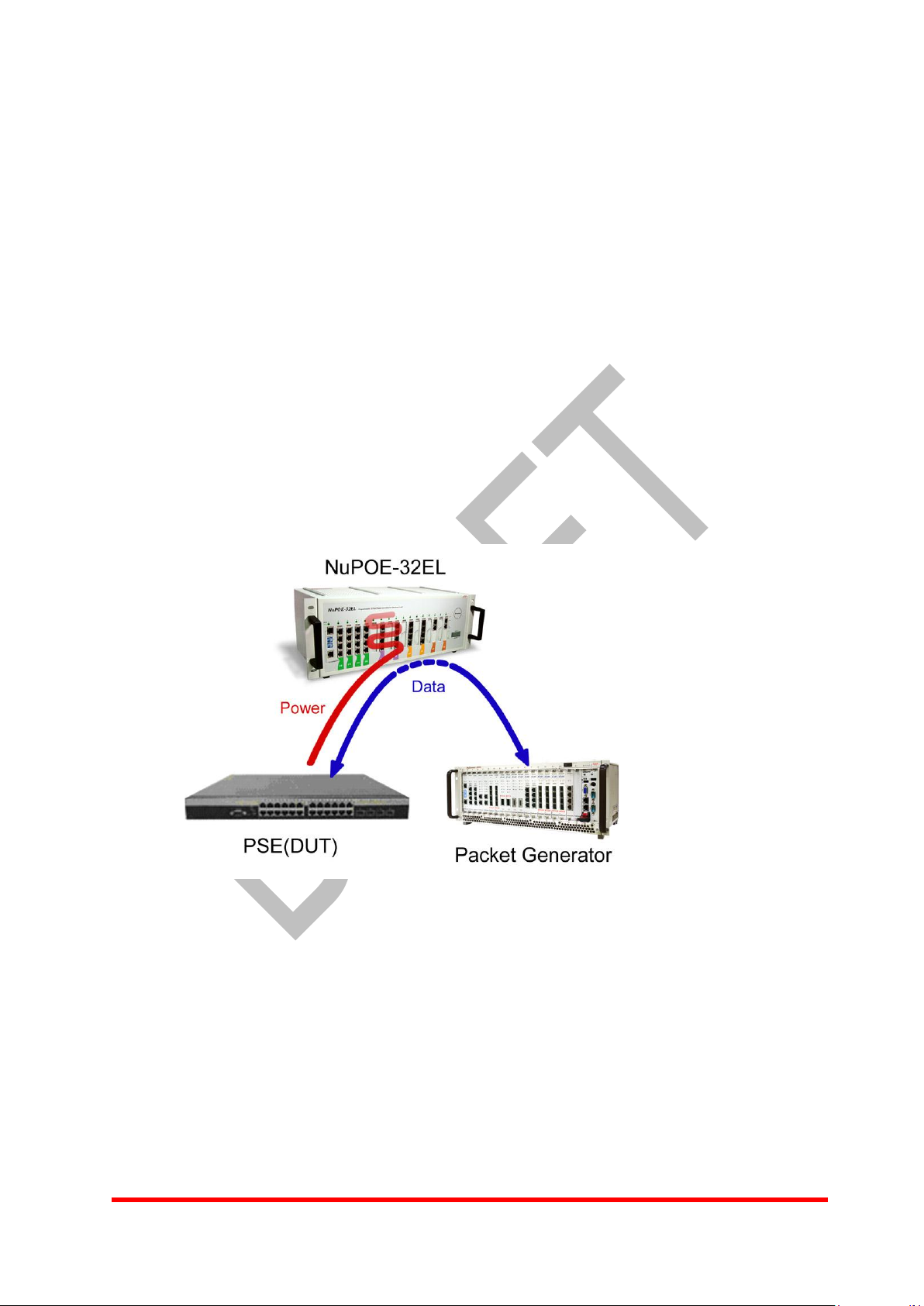
1.2 Application Diagram
Connect PSE port(s) and PD / Switch port(s) of NuPOE-32EL to the DUT. User can
use the NuApps-POE to control and analyze data via the connection between the
Management port of NuPOE-32EL and the PC with NuApps-POE.
1
Page 6
E-Mail: sales@xtramus.com
Http://www.Xtramus.com
XTRAMUS TECHNOLOGIES®
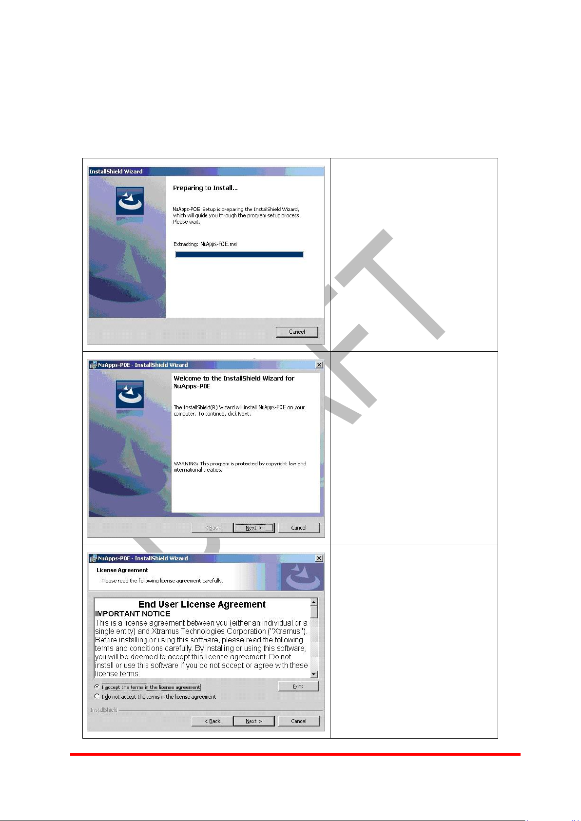
The setup is preparing process.
Click Cancel to cancel at any
time and exit the process.
Click Next to continue the
installation.
Read License Agreement
carefully and click the radio
button to accept the terms. Click
Next to for next step. Click Back
to review any installation
settings.
2. Installation and Uninstallation
2.1 Installation
Double click on the icon of NuApps-POE setup.exe to activate NuApps-POE setup.
2
Page 7
E-Mail: sales@xtramus.com
Http://www.Xtramus.com
XTRAMUS TECHNOLOGIES®
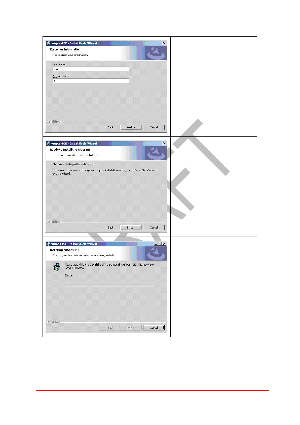
Input information of user name
and organization, and then click
Next for next step.
Click Install to start installing the
program.
The installation is in process.
3
Page 8
E-Mail: sales@xtramus.com
Http://www.Xtramus.com
XTRAMUS TECHNOLOGIES®
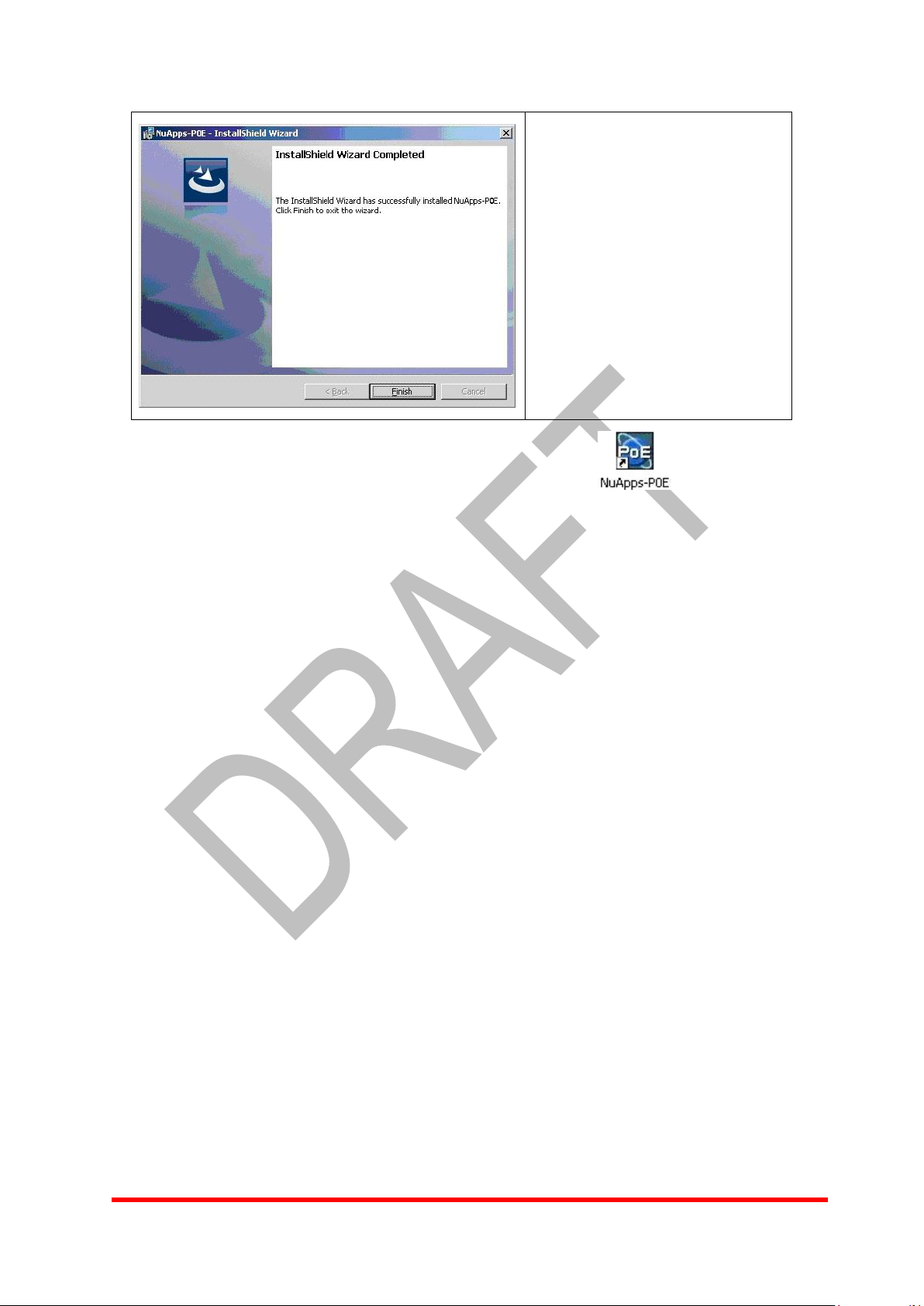
Installation is complete. Click
Finish to exit the program.
The installation of NuApps-POE is successful. Now the icon appears on
the desktop.
2.2 Uninstallation
If applications do not work properly or Xtramus may periodically update new version of
NuApps-POE software, it is necessary to uninstall previous NuApps-POE first.
There are 2 places to uninstall the program:
1. Go to Start menu > Programs > NuStreams > NuApps-POE > Uninstall.
2. Or Control panel > Add/Remove Programs > NuApps-POE >
Change/Remove.
4
Page 9
E-Mail: sales@xtramus.com
Http://www.Xtramus.com
XTRAMUS TECHNOLOGIES®
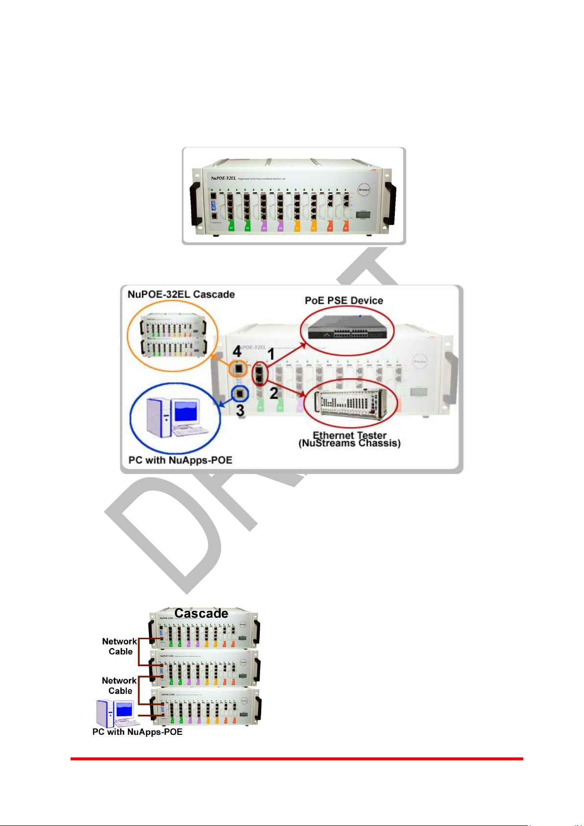
3. NuPOE-32EL Setting
Before NuApps-POE start, user must set the connection of NuPOE-32EL with PoE
PSE device.
The setup diagram as below:
1) User can connect NuPOE-32EL to PoE PSE device via Port 1 and Port 3 on the
every module slot
2) User can connect NuPOE-32EL to Ethernet tester via Port 2 and Port 4 on the
every module slot.
3) The port 2 on the first slot, on the left side of NuPOE-32EL, is the exclusive port of
the connection between the NuPOE-32EL and PC with NuApps-POE.
4) The function of Port 1 and Port 2 on the first slot is for the cascade.
5
Page 10
E-Mail: sales@xtramus.com
Http://www.Xtramus.com
XTRAMUS TECHNOLOGIES®
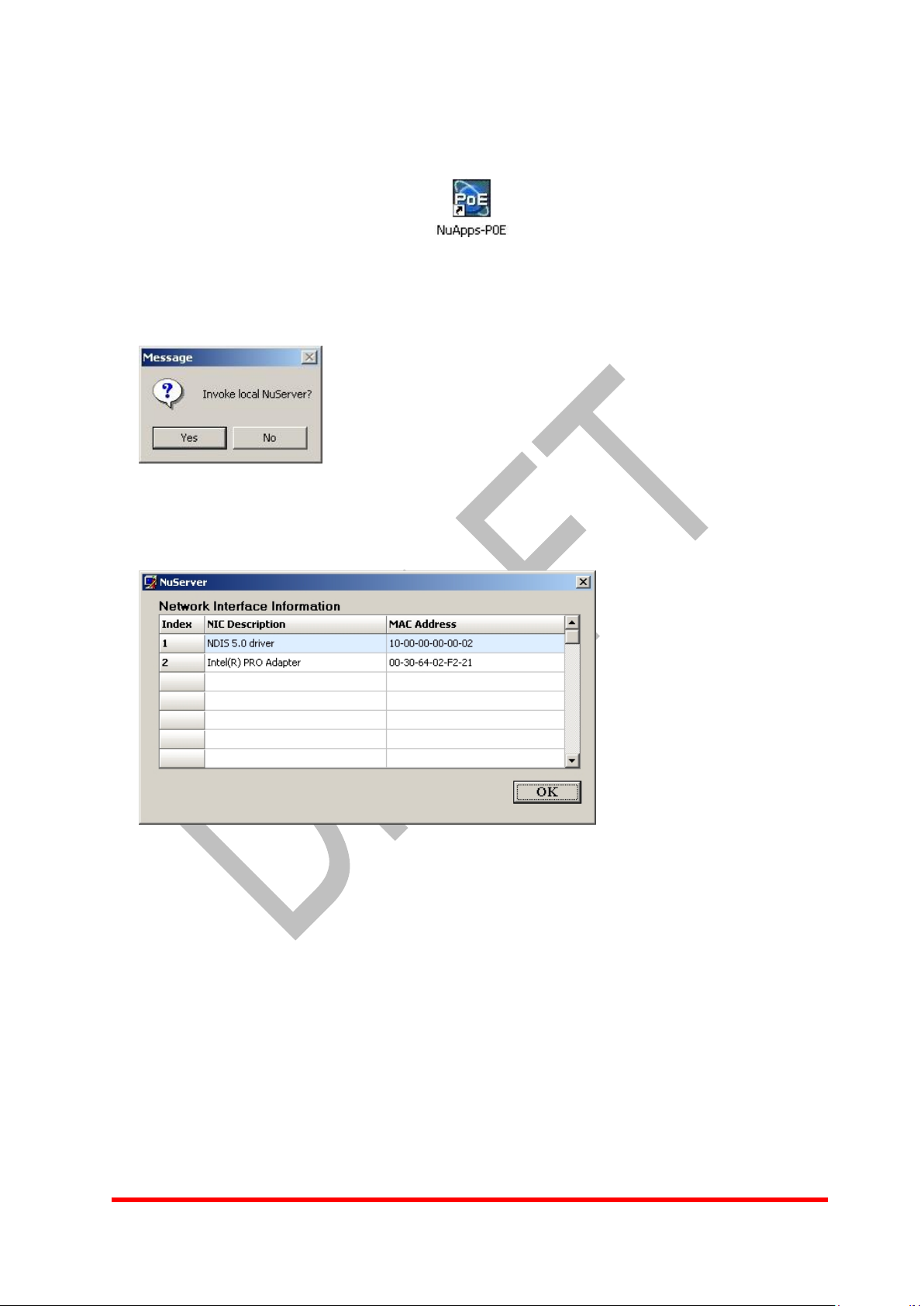
4. Quick Start
Double click on the NuApps-POE icon on the desktop to start
NuApps-POE program. A message window appears to inquire about invoking the
local server if it is connected to one.
Click Yes button and the NuServer window will appear.
Choose the NIC to which NuPOE-32EL is connected. Then click OK button to activate
NuServer.
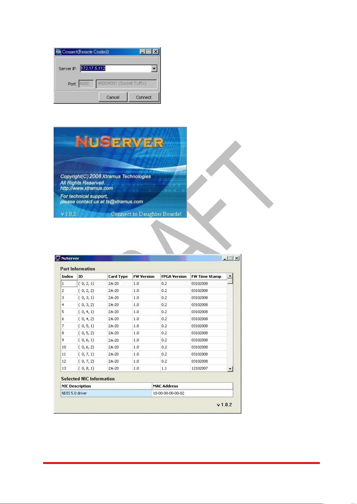
Click No button, the Connect window will appear to input server IP if NuPOE-32EL is
connected to a remote server. Click Connect button.
6
Page 11
E-Mail: sales@xtramus.com
Http://www.Xtramus.com
XTRAMUS TECHNOLOGIES®
NuServer has been activated.
7
Page 12
E-Mail: sales@xtramus.com
Http://www.Xtramus.com
XTRAMUS TECHNOLOGIES®
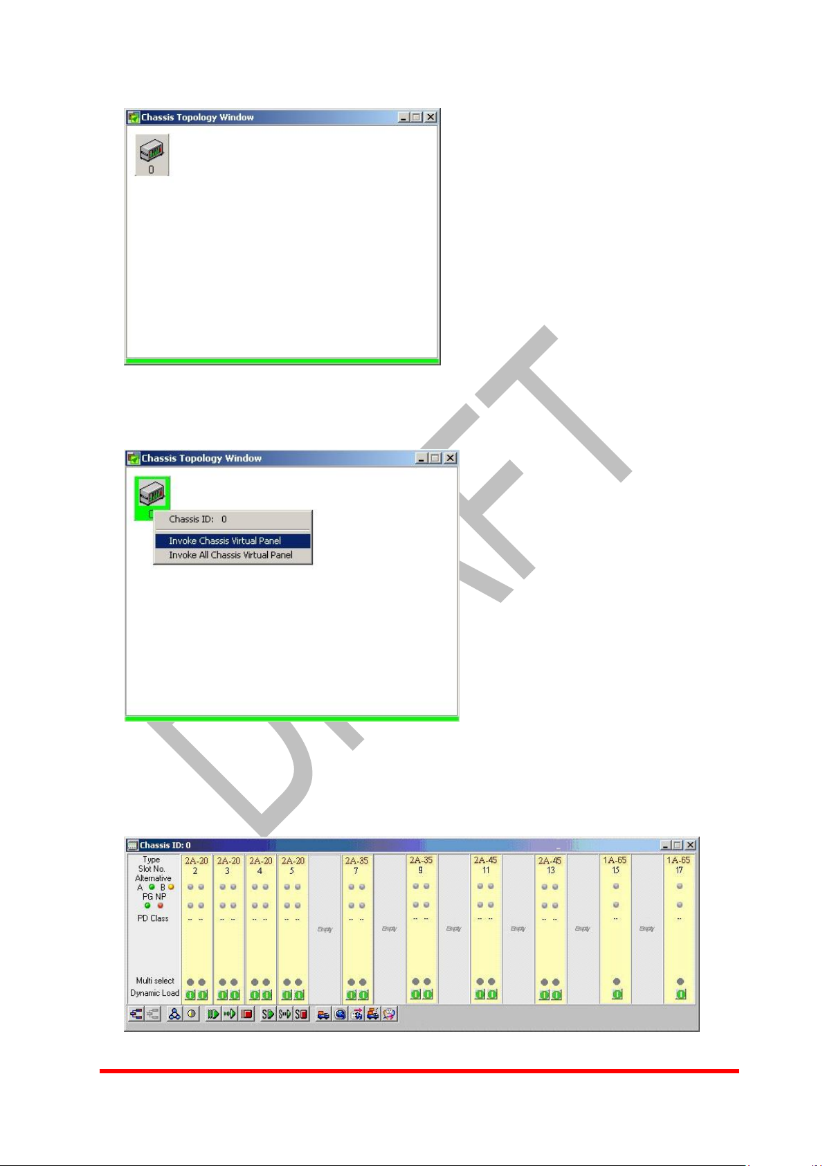
Chassis topology window appears to display the chassis ID connected.
Click right mouse on the ID to bring out the popup menu and invoke the chassis virtual
panel.
The virtual panel of NuApps-POE program appears.
8
Page 13
E-Mail: sales@xtramus.com
Http://www.Xtramus.com
XTRAMUS TECHNOLOGIES®
Menu Choice
Shortcut
Usage
Load
Ctrl+ L
Presents a dialogue to load workspace from the disk.
Save
Saves the current information to the current workspace in
use.
Save As
Ctrl+ A
Presents a dialogue to save the current workspace to the
disk.
Exit
Ctrl+ E
Exits NuApps-PoE program.
Menu Choice
Shortcut
Usage
Chassis Topology Window
Ctrl+ T
Invokes Chassis Topology window.
All Chassis Panel
Ctrl+ Alt+ V
Invokes all chassis panel.
Show Server
Invokes NuServer window when visible at
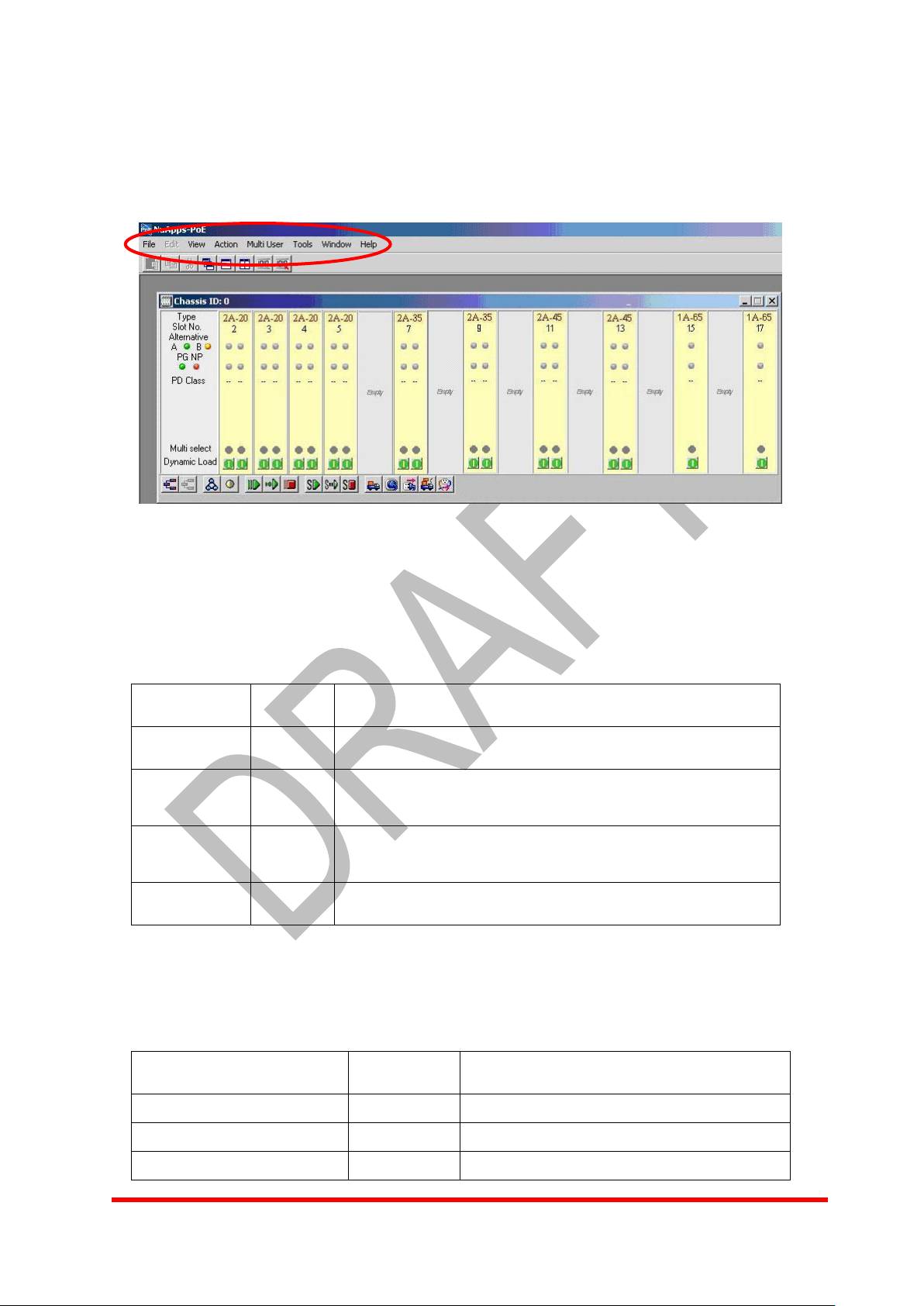
5. Function Description
5.1 Main Window
The top level menus of NuApps-POE include: File Menu, Edit Menu, View Menu,
Action Menu, Multi User Menu, Tools Menu, Window Menu and Help Menu.
The choices for File Menu are described in the table below:
View Menu is divided into Control Menu and Report Menu.
The choices for Control Menu are described in the table below:
9
Page 14

E-Mail: sales@xtramus.com
Http://www.Xtramus.com
XTRAMUS TECHNOLOGIES®
the task management but invisible at the
taskbar.
Menu Choice
Shortcut
Usage
Counter Window
Ctrl+ W
Invokes Counter window.
Log Window
Ctrl+ O
Invokes Log window.
Menu Choice
Shortcut
Usage
Connect
Invokes to connect to a local server when it’s enabled.
Menu Choice
Shortcut
Usage
Release My Ownership
Releases the current chassis.
Release All Ownership
Releases all chassis.
Reserve All Chassis
Reserves all chassis.
Menu Choice
Shortcut
Usage
Option
Ctrl+ P
Invokes Preference window.
The choices for Report Menu are described in the table below:
The choices for Action Menu are described in the table below:
The choices for Multi User Menu are described in the table below:
The choices for Tools Menu are described in the table below:
10
Page 15

E-Mail: sales@xtramus.com
Http://www.Xtramus.com
XTRAMUS TECHNOLOGIES®
Menu Choice
Shortcut
Usage
Cascade
Ctrl+ S
Arranges all windows in cascade.
Tile Horizontally
Ctrl+ H
Arranges all windows horizontally.
Tile Vertically
Arranges all windows vertically.
Minimize All
Ctrl+ I
Minimizes all windows.
Menu Choice
Shortcut
Usage
Xtramus Web
F3
Links to the official website of Xtramus Technologies
About
Ctrl+ B
Provides information regarding the current version of
NuApps-PoE.
The choices for Window Menu are described in the table below:
The choices for Help Menu are described in the table below:
11
Page 16

E-Mail: sales@xtramus.com
Http://www.Xtramus.com
XTRAMUS TECHNOLOGIES®
Figure
Usage
Makes a paste.
Makes a copy.
Makes a cut.
Arranges all windows in cascade.
Arranges all windows horizontally.
Arranges all windows vertically.
Views Counter window.
Views multi selected counters in Counter window.
5.2 Toolbar Function
The buttons in the main window toolbar are described in the table below:
12
Page 17

E-Mail: sales@xtramus.com
Http://www.Xtramus.com
XTRAMUS TECHNOLOGIES®
Figure
Usage
Reveres all boards.
Releases all boards.
Invokes browse setup.
Multi select toggle.
Starts test (all and concurrent).
Starts testing (all and sequence).
Stops dynamics loading (all).
Starts test (selected ports and Concurrent).
Starts test (selected ports and Sequence).
Stops dynamic loading (selected ports).
Invokes dynamic loading.
Invokes connect test.
Invokes disconnect test.
5.3 Chassis Panel
5.3.1 Toolbar Function
The buttons in the chassis panel tool bar are described in the table below:
13
Page 18

E-Mail: sales@xtramus.com
Http://www.Xtramus.com
XTRAMUS TECHNOLOGIES®
Invokes overload test.
Invokes short-circuit test.
Item
Symbol/Color
Description
N/A
Card Type.
N/A
Slot Number.
Green
Alternative A: sends power via pin 1, 2, 3 and 6.
Orange
Alternative B: sends power via pin 4, 5, 7 and 8.
Green
Power status of the port is good. (Power Good)
Red
Power status of the port is not active. (No Power)
N/A
PD class level 0 ~ 4.
Green
Port selected.
Gray
Port unselected.
Green
Stops dynamic loading
Red
Invokes dynamic loading
5.3.2 LED Indicators
LED Indicators in the chassis panel are described in the table below:
14
Page 19

E-Mail: sales@xtramus.com
Http://www.Xtramus.com
XTRAMUS TECHNOLOGIES®
5.4 Popup Menu
Move the cursor to any of the module cards on the chassis panel and right mouse
click to bring out the popup menu of the current port.
15
Page 20

E-Mail: sales@xtramus.com
Http://www.Xtramus.com
XTRAMUS TECHNOLOGIES®
6. Operation
6.1 Reserve and Release
Before making any testing configurations, click on Reserve (Chassis) or to
reserve the entire chassis of individual module cards.
If the chassis is shared by multiple users, bring out the popup menu and choose
Reserve (Current Board) to reserve the card for own use.
To disable the reserve function, click on the Release (Current Board)/ Release
(Chassis) or . The reserved ports will be released.
The Message bar indicates the processing status of reserve chassis. It is the same
with releasing chassis.
16
Page 21

E-Mail: sales@xtramus.com
Http://www.Xtramus.com
XTRAMUS TECHNOLOGIES®
6.2 Copy and Paste Port Data
Copy the testing setup of the current port. Make further configurations by copying the
settings of the current port.
Then paste the copied port data to the current port or multiple ports through the
chassis window.
6.3 Multi Select
Choose All Selected (Chassis) to select all ports in the chassis for testing
configuration.
Choose All Reset (Chassis) to reset all ports in the chassis.
Choose Multi Selected Toggle to toggle between the set ports and the reset ones.
17
Page 22

E-Mail: sales@xtramus.com
Http://www.Xtramus.com
XTRAMUS TECHNOLOGIES®
Move the selected ports one by one.
Move all the ports at once.
6.4 Setup
6.4.1 Browse Setup
Press button from bottom toolbar of the chassis panel to bring up the Browse
Setup window.
Press to bring out the port selection dialogue. Use the arrow key(s) to select the
port(s). Click OK button after completion to close the dialogue.
18
Page 23

E-Mail: sales@xtramus.com
Http://www.Xtramus.com
XTRAMUS TECHNOLOGIES®
PD Class
Usage
PD Standard Watt
0
Default
0.44 ~ 12.95
1
Optional
0.44 ~ 3.84
2
Optional
3.84 ~6.49
3
Optional
6.49 ~ 12.95
4
Optional
--- *
After all the settings are complete, press the button Apply for each individual port or
Apply All for all the ports at once. A message for settings complete will appear. Press
the individual Request button(s) or the On All button to run loading. Press
the individual Request button(s) or the Off All button to stop loading. At
last, click Close button to exit the browse setup.
It is available to save or to load a configuration by click Load Cfg button or Save Cfg
button at the left lower corner.
PD class is based on IEEE 802.3af standard.
* Class 4 is currently reserved.
19
Page 24

E-Mail: sales@xtramus.com
Http://www.Xtramus.com
XTRAMUS TECHNOLOGIES®
6.4.2 Setup PD Property
The dialogue window appears.
Five PD (powered devices) classes of power level are supported. Click the radio
button to select the class signature.
20
Page 25

E-Mail: sales@xtramus.com
Http://www.Xtramus.com
XTRAMUS TECHNOLOGIES®
Both alternative wirings are supported. Alternative A refers to send power along with
pin 1, 2, 3 and 6 while alternative B refers to send power along with pin 4, 5, 7 and 8.
6.4.3 Setup Dynamic Loading
There are four (4) loading levels available. Check the Enable box(es) and mark the
power value on the ruler or use the up or down arrow keys to determine the
21
Page 26

E-Mail: sales@xtramus.com
Http://www.Xtramus.com
XTRAMUS TECHNOLOGIES®
Range: 0 to 2,000 ms
Range: 2 to 16 seconds
designated power value and the duration for the loading level. The time (sec) for each
loading has to be greater than 2 seconds. The loading operates in Constant Power
(CP) mode and displays in scales from 0.8 to 20 Watt. The capacity could support up
to 15.4 Watt per port continuously and 19 Watt for short-term overload tests.
Input the total loading duration in seconds. The time for total loading period has to be
greater than 2 seconds.
Click Apply button after all setups.
6.4.4 Setup Connect Test
22
Page 27

E-Mail: sales@xtramus.com
Http://www.Xtramus.com
XTRAMUS TECHNOLOGIES®
Range: 0 to 2,000 ms
Range: 2 to 16 seconds
6.4.5 Setup Disconnect Test
23
Page 28

E-Mail: sales@xtramus.com
Http://www.Xtramus.com
XTRAMUS TECHNOLOGIES®
6.4.6 Setup Overload Test
Set up the pulse load and the idle load for overload configuration. Pulse load refers to
the maximum value once the power shoots up while idle load refers to the lowest
value when loading drops off.
24
Page 29

E-Mail: sales@xtramus.com
Http://www.Xtramus.com
XTRAMUS TECHNOLOGIES®
Range: 2 to 16 seconds
6.4.7 Setup Short Circuit Test
25
Page 30

E-Mail: sales@xtramus.com
Http://www.Xtramus.com
XTRAMUS TECHNOLOGIES®
6.5 Start Test
There are two places to start any test: choose from the popup menu or click the small
figure from the bottom of the chassis panel.
6.5.1 Start Dynamic Loading
The indicator for the dynamic loading from the virtual panel will appear to indicate
the port(s) is/are running dynamic loading test.
6.5.2 Start Connect Test
26
Page 31

E-Mail: sales@xtramus.com
Http://www.Xtramus.com
XTRAMUS TECHNOLOGIES®
Initial chart title
Check the Visible box for the power measurements of Voltage and/or Current to show
the information in chart.
Cursor 1- Refers to the value at the Cursor 1 position. Click on any point on chart with
the mouse and Shift button at the same time to move the cursor and to change the
value.
Cursor 2- Refers to the value at the Cursor 2 position. Click on any point on chart with
the mouse and Ctrl button at the same time to move the cursor and to change the
value.
Delta- Refers to the difference of the values between Cursor 1 and Cursor 2.
Delta Time (ms)- Refers to the time difference between Cursor 1 and Cursor 2.
On the right side of the chart, Report shows different power measurements of the
results for different tests.
For Connect Test, there are Iclass (mA), T pdc (ms) and Power Status (Power
Good/No Power).
To title the chart, input a title in a pane under Set Chart Title, then press Set button to
27
Page 32

E-Mail: sales@xtramus.com
Http://www.Xtramus.com
XTRAMUS TECHNOLOGIES®
put the title in chart.
Re-start the test by clicking the Test button; save the current chart by clicking the
Save Chart button; exit the chart by clicking the Close button.
6.5.3 Start Disconnect Test
For Disconnect Test, the report shows T off (ms) and Test Result (Success/Fail).
28
Page 33

E-Mail: sales@xtramus.com
Http://www.Xtramus.com
XTRAMUS TECHNOLOGIES®
6.5.4 Start Overload Test
For Overload Test, the report shows Icut (mA), T ovld (ms) and State (Overload
Occurs/No Overload).
29
Page 34

E-Mail: sales@xtramus.com
Http://www.Xtramus.com
XTRAMUS TECHNOLOGIES®
6.5.5 Start Short Circuit Test
For Short Circuit Test, the report shows Ilim (mA), T lim (ms) and State (Short Circuit
Occurs/No Short Circuit).
30
Page 35

E-Mail: sales@xtramus.com
Http://www.Xtramus.com
XTRAMUS TECHNOLOGIES®
6.6 Stop Dynamic Loading
Since dynamic loading is a constant activity, click right mouse on the module card to
bring out the popup menu and press Stop Dynamic Loading to stop.
6.7 View Counter
For any types of loading or dynamic loading, view counter window for result analysis.
31
Page 36

E-Mail: sales@xtramus.com
Http://www.Xtramus.com
XTRAMUS TECHNOLOGIES®
Figure
Usage
Exports the current counter window to an Excel file.
Prints out the information of the counter window via printer.
Invokes port mapping.
Resets port mapping.
Clears selected counter.
Adjusts column height.
Toolbar
32
Page 37

E-Mail: sales@xtramus.com
Http://www.Xtramus.com
XTRAMUS TECHNOLOGIES®
6.8 Control
It is also available to invoke Chassis Topology Window here to check chassis ID.
6.9 Report
6.9.1 Counter Window
It is also available to invoke Counter Window here.
33
Page 38

E-Mail: sales@xtramus.com
Http://www.Xtramus.com
XTRAMUS TECHNOLOGIES®
6.9.2 Card Version Information
Check Report> Card Version Information> Card version to bring out the FPGA
version of the port. Click OK button to exit the dialogue.
Update Firmware/FPGA
Select port and the new location of the new Firmware and press Download for Port
to update Firmware or FPGA. Or check the box of the card name and press
Download for Chassis to update Firmware or FPGA.
34
Page 39

E-Mail: sales@xtramus.com
Http://www.Xtramus.com
XTRAMUS TECHNOLOGIES®
6.9.3 Log window
Log report includes the detailed operation log: date, time and log event.
35
Page 40

E-Mail: sales@xtramus.com
Http://www.Xtramus.com
XTRAMUS TECHNOLOGIES®
6.10 Log
36
Page 41

E-Mail: sales@xtramus.com
Http://www.Xtramus.com
XTRAMUS TECHNOLOGIES®
6.10.1 Load Test Log
Look in the folders to open an existed test report log in .rpt format.
6.10.2 Remove Log File
A message window will pop up to confirm to remove all log files after clicking Remove
Log File from popup menu. Click Yes to proceed or No to cancel.
37
Page 42

E-Mail: sales@xtramus.com
Http://www.Xtramus.com
XTRAMUS TECHNOLOGIES®
6.11 Reset Factory Default Value
It is applicable to reset any factory default values by clicking Reset Factory Default
Value. A Reset finish dialogue will appear after it is complete. Click OK button to close
the dialogue.
38
Page 43

E-Mail: sales@xtramus.com
Http://www.Xtramus.com
XTRAMUS TECHNOLOGIES®
Note: Information and specifications contained in this document are subject to change without notice.
All products and company names are trademarks of their respective corporations.
Copyright © 2010 Xtramus Technologies, all rights reserved.
Do not reproduce, redistribute or repost without written permission from Xtramus.
Doc #USM_NuApps-POE_V1.0_ENG_20111111
39
 Loading...